4 minute read
Rangeview Sanitary Trunk Project Challenges and Mitigation Measures


Project Challenges And Mitigation Measures
Shaft Construction
The original design was to install Shaft 2 was through excavation and lowering castin-place concrete. The contractor modified the design later at the beginning of the construction to the precast segmental wall which was shipped from Europe. The precast segmental construction helped in expediting the project work as it doesn’t require curing of concrete which could have been costly and time-consuming particularly in winter.
Groundwater Pressure
One of the issues of the project during construction was the high groundwater table. The entire trunk profile is below the high groundwater level. At Shaft 2, the high groundwater table is almost at the mid-depth of the shaft, which is about 50% of the shaft is below the high groundwater table. This created a challenge in shaft construction. At the depth of about 18 m (60 ft) from the ground surface, buckling of the shaft segmental walls, and some leakages was observed due to increased lateral pressure from the groundwater. This was observed at multiple locations and as a result, the contractor had to stop further excavation.
Mitigation measures taken by the contractor to overcome the problem included:
• Pumping water into the shaft to the level of high groundwater level to counterbalance the lateral pressure
• Grout at the back of the segmental wall through the grout portals to stop the leaks
• Continue excavation underwater using a clamshell excavator
The subsurface soil formation was silt and silty sand, and which made excavation underwater difficult. It was a very slow process; as the result, the schedule of shaft construction and the overall project was impacted by more than three weeks.
Void Formation
Most of the project site passes through a new development community where several underground infrastructures are constructed or under construction. One of these infrastructures is a new 525 mm (20”) sanitary line installed for future connection to Shaft 2. This line was supposed to be plugged at the end and at the upstream manholes. However, the Developer who built the line didn’t plug or notify the City of the situation. As a result, stormwater has been flowing through the line and accumulated at the end of the pipe. This was ongoing for over a month until it was discovered due to void formation behind Shaft 2. The void formation was so large that the segmental wall was moved, and the shape of the shaft was distorted. To mitigate the issue, the contractor did the following:
• Sucked out the stored water in the pipe and the manholes using vacuumed trucks
• Provided their own air plugs at the manholes to prevent any accidental flow
• Inspected the air plug on a regular basis
• Filled the void spaces with lean concrete
• Constructed a new 2 m (6 ft) high structural collar at the base around the segmental wall to ensure the stability of the shaft
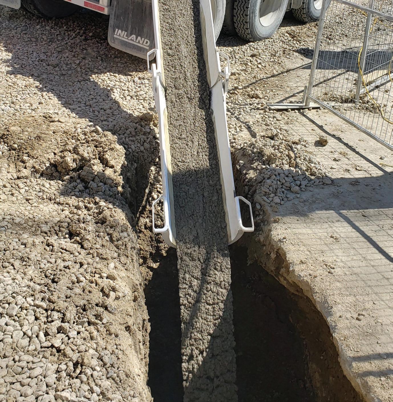
The contractor’s filling of the void space with lean concrete and construction of the structural envelope is shown in Figure 2 and Figure 3 respectively.
To fill the void space, about 120 cu.m (160 cu.yd.) of lean concrete was used. Overall, it took three weeks to fix the issue and resulted in a claim of about $520,000.
Flooding of Shaft
The shaft site was lowered by 2 m from the existing ground to match future road final grade and the site drainage is managed through collection into a sump at a low point and pumping out from the sump to outside the area. Heavy rainfall on August 7, 2020, between 4:30 a.m. and 6:30 a.m. flooded the entire Shaft 2 site.
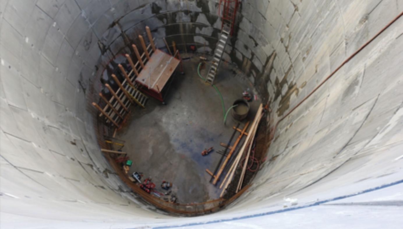
The sump doesn’t have a level monitoring system in place to notify the site superintendent. The water level is monitored through physical observation inside the sump whenever there is any rainfall event. This rainfall happened in the early morning when there was no site superintendent except the security guard. As a result, there was no one in charge of pumping out the stormwater, and the area was flooded. Water entered into Shaft 2 and submerged the MTBM, the jacking frame, and all the control systems installed in the shaft. Figure 4 shows the flooded condition of the shaft.
The contractor had to take out the stored water and replace all the damaged equipment. It took about six weeks to get the parts and install and bring the system back into operation. The estimated cost of damage without the standby time was about $400,000 USD.
Tunnelling
Crossing a Highway
RST crosses under Deerfoot Trail, a highway that has an average daily average traffic volume of over 110,000 vehicles. The tunnel under this highway has the longest drive, about 936 m (3,080 ft). Due to predetermined tie-in elevation, the tunnel profile could not be lowered at the highway. The depth of cover gets to less than 3 m (10 ft) at the ditches next to the highway.
During the design stage, the crossing of the highway was identified as the riskiest item out of all the risks identified in the project. To address the risk, some design stage mitigation measures were implemented.
These include:
• Providing monitoring point along the highway crossing to measure any potential settlement due to tunnelling
• Client took third party insurance cover for any potential claim due to damage to the highway or disruption of traffic flow
During construction, the following mitigation measures were taken by the project team to reduce the potential risks:
• Reduced the tunnelling speed at the highway crossing
• Reduced tunnelling target pressure at the highway crossing
• Established a cleaning crew with hydrovac equipment and kept the crew on site for 24 hours in on standby in case of any frac-out
• Notified the City council and the community ahead in case of any emergency and road shutdowns
• Notified the administrator of the highway
• Notified police and emergency
• Project managers from the Client, the Contractor, and the Consultant were available for 24 hours to make decisions in case of emergency
At the end crossing at the highway was successfully completed without any major issue.
Exit Portal Located at Environmentally Sensitive Area
The exit portal of the first drive is located adjacent to an environmentally sensitive area. The area downstream is designated as an Environmental Reserve that consists of wetlands and rare plant species. During the design stage, the project went through a long regulatory approval process and approval was later granted with strict conditions. To make the situation worse, the slope at the embankment is unstable due to lose silty soil formation. There have been several slope failures in the past at the embankment and if that happens again, there is a risk of frac-out to the downstream environment.
To minimize the risk, the following mitigation measures were taken:
• Lock blocks were built up to support the embankment
• The bottom of the exit portal was lowered to contain the slurry
• The bottom layer was sealed to avoid any infiltration into the ground
• Hydrovac machine was placed on standby 24 hours in case of any potential escape of slurry


