
Document Title: Function Group: Information Type:
Date:
Engine, description 200 Service Information 2015/3/16
Profile:
EXC, EC330B LC [GB]
Go back to Index Page
Engine, description
Machine serial no. EC330B: 10001 ~ 10235, EC360B: 10001 ~ 10828
The engine is a straight six cylinder, four stroke, direct injection diesel with 9.6 liter cylinder volume, turbocharged, inter cooled and electronic controlled fuel injection, EMS (Engine Management System), with a cast iron block and cylinder head. The cylinder block and head are designed with internal passages formed as sets for lubrication and cooling.
An engine driven power take off for a hydraulic pump can be provided for the D10 as extra equipment
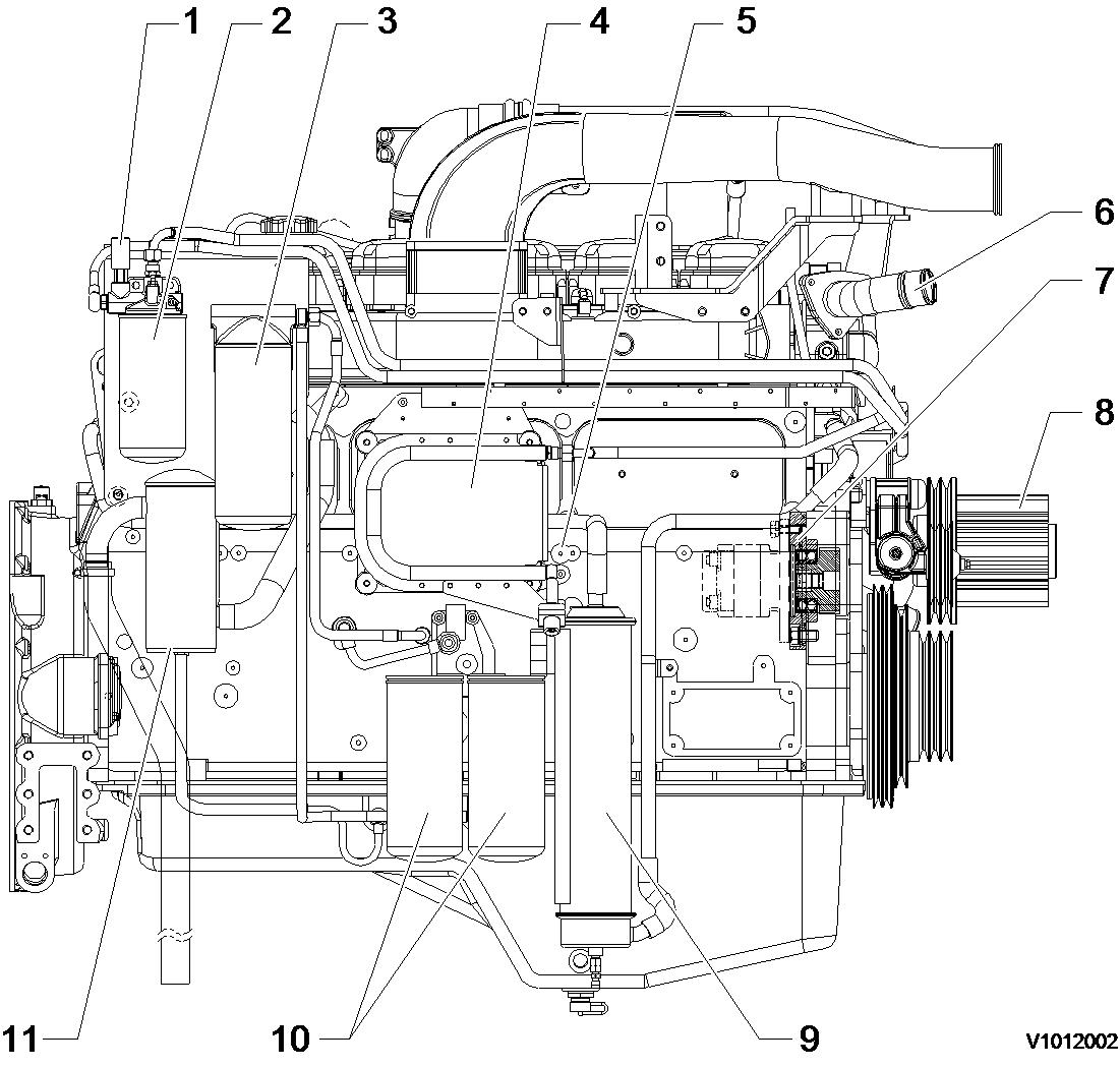
Structure, fuel filter side view
Engine, fuel filter side view
Fuel feed pump
Fuel filter
Engine oil filter (bypass)
EMS (Engine Management System)
Fuel inlet
Water outlet
Engine PTO (Power Take Off)
Fan drive and pulley

Oil cooler
Engine oil filter (full)
Breather
Structure, turbocharger side view
Fuel pump
Turbocharger

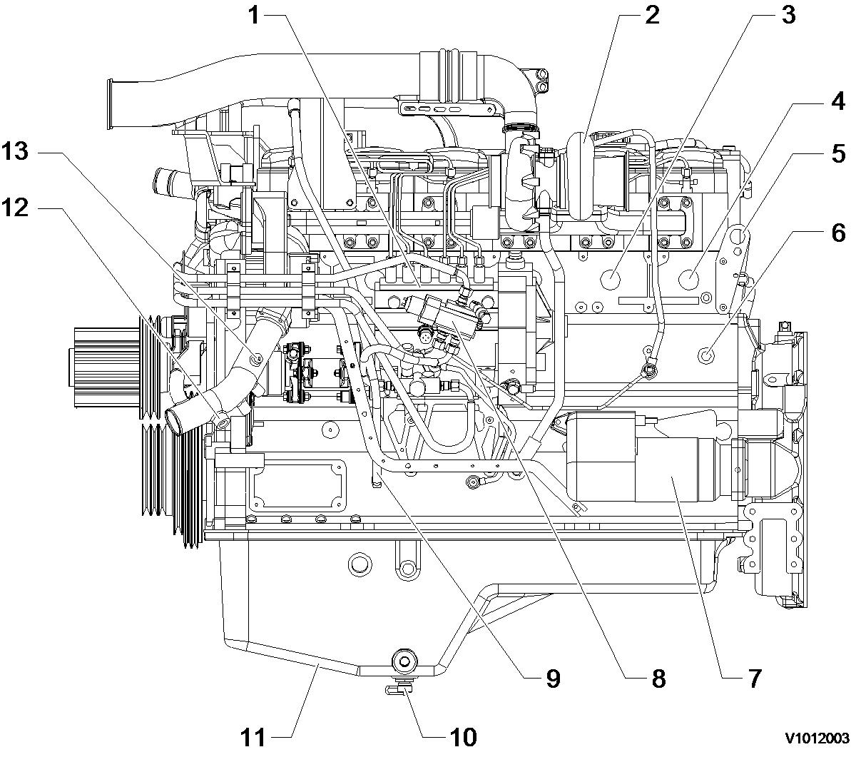
Cooler block heater (1 3/4″ -16UN - 2B)
Cab heater supply (1/2″ - 14UPSI)
Engine lifting eye
Coolant filter heater (1/2″ - 14UPSI)
Starter
Fuel shut off solenoid
Dipstick
Oil drain valve
Oil pan
Coolant filter return (M 22 × 1.5)
Cab heater return (M 22 × 1.5)
Structure, top view
Figure 2Engine, top view

Air intake port Oil filter (bypass) Coolant vent Air exhaust port
Structure, front side view
Engine, front side view
Dipstick gauge Water inlet Alternator
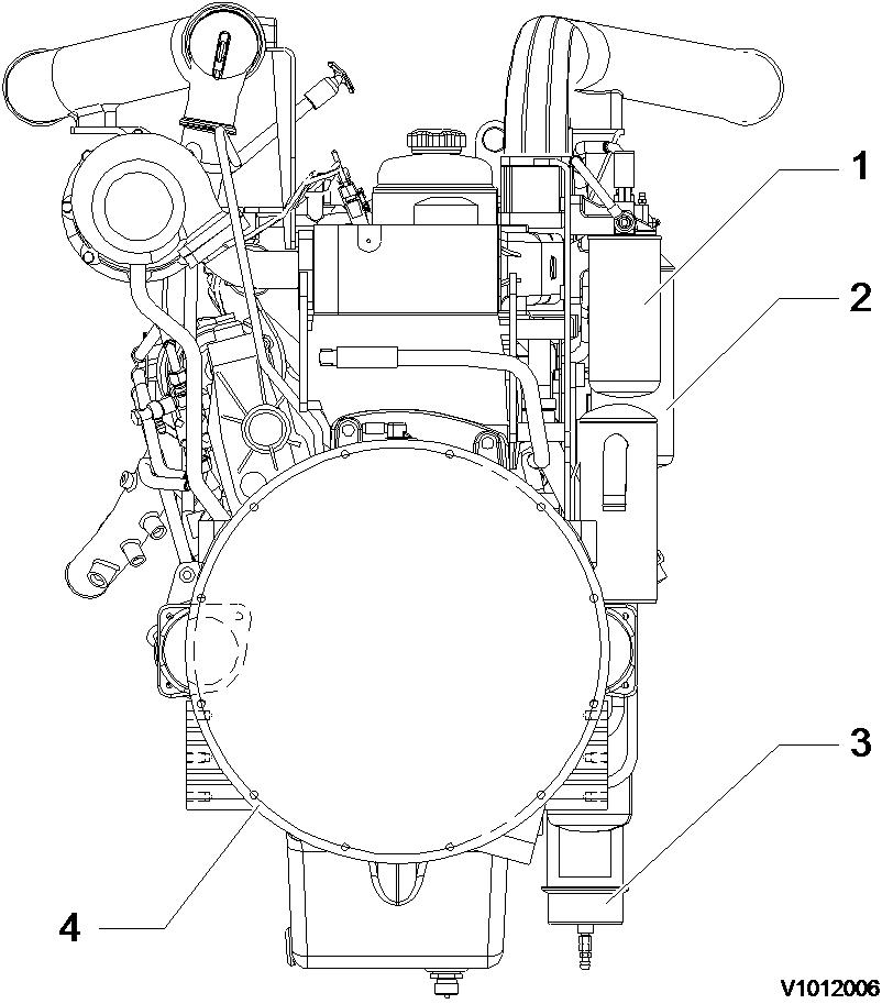
Structure, rear side view
1. 2. 3. 4. Figure 4 1. 2. 3. Figure 5Engine, rear side view
1. 2. 3. 4. Fuel filter Oil filter (bypass) Oil cooler Flywheel housingDocument Title: Function Group: Information Type:
Date:
Engine, description 200 Service Information 2015/3/16
Profile:
EXC, EC330B LC [GB]
Go back to Index Page
Engine, description
Machine serial no. EC330B: 10236 ~ 10712, EC360B: 10829 ~ 12151
D12C EC(D,E)E2 is the model number of the volvo 12 liter engine for the EC330B/360B excavator.
The engine is a 6-cylinder, 4-stroke, direct injection diesel with a 12 liter cylinder volume, turbocharger, charged air cooler and electronic controlled fuel injection, EMS (Engine Management System).
The serial number of the engine is to be found stamped in the cylinder block on the rear left side.
The cylinder head is of cast iron and manufactured in one piece which is necessary in order to provide stable bearings for the overhead camshaft.
The cylinder liner is sealed against the coolant casing with rubber rings.
The D12C EC(D,E)E2 has a four-valve system and overhead camshaft.
The engine timing gear transmission is located at the front of the engine on a 10 mm thick steel plate bolted to the cylinder block.
The crankshaft is drop forged and has induction hardened bearing surfaces and fillets.
The engine is force fed lubricated by an oil pump which is gear driven from the engine crankshaft via an intermediate gear
The fuel system for D12C EC(D,E)E2 has electronic control with unit injectors one for each cylinder and which operate at a very high pressure.
The fuel feed pump is a gear driven type and is driven from the engine timing gear with the same gear.
Engine, structure
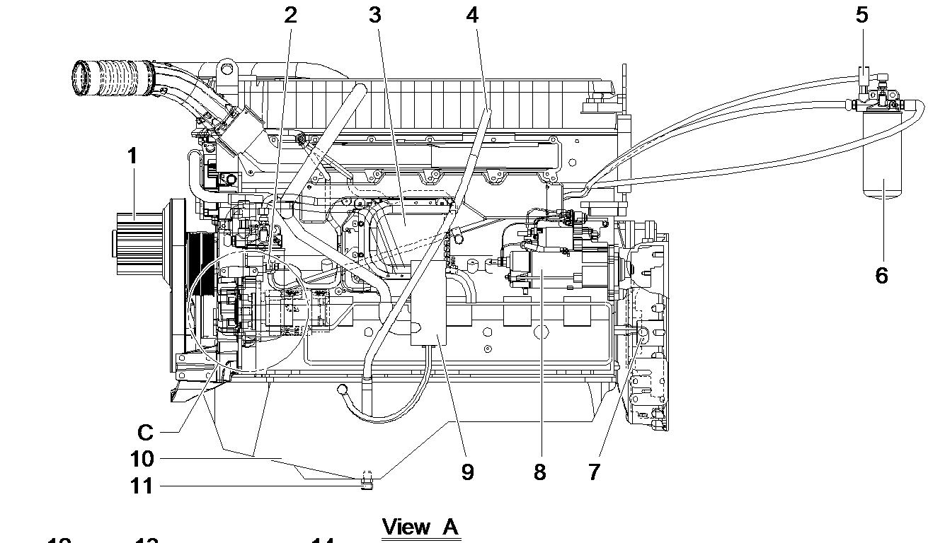
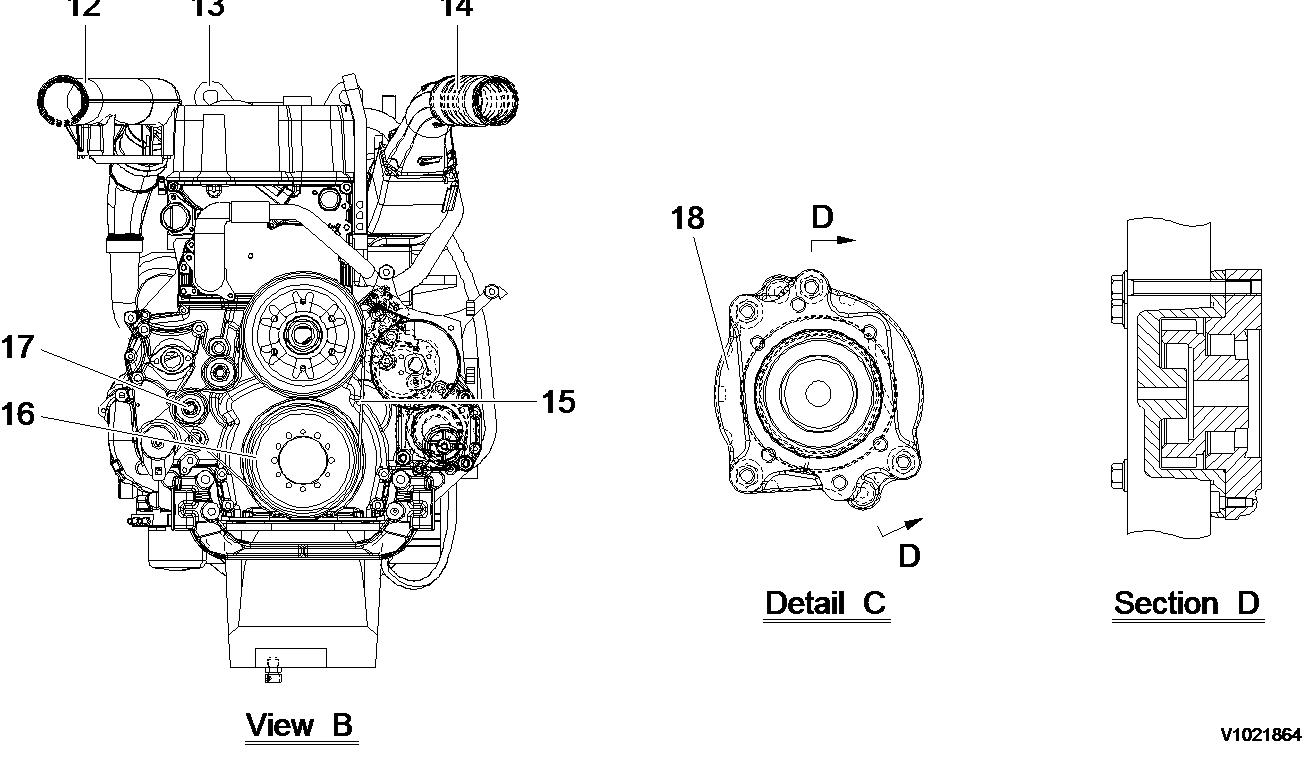 Figure 1
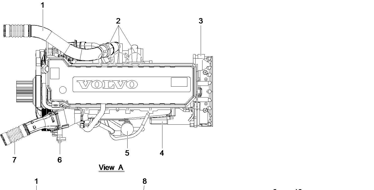
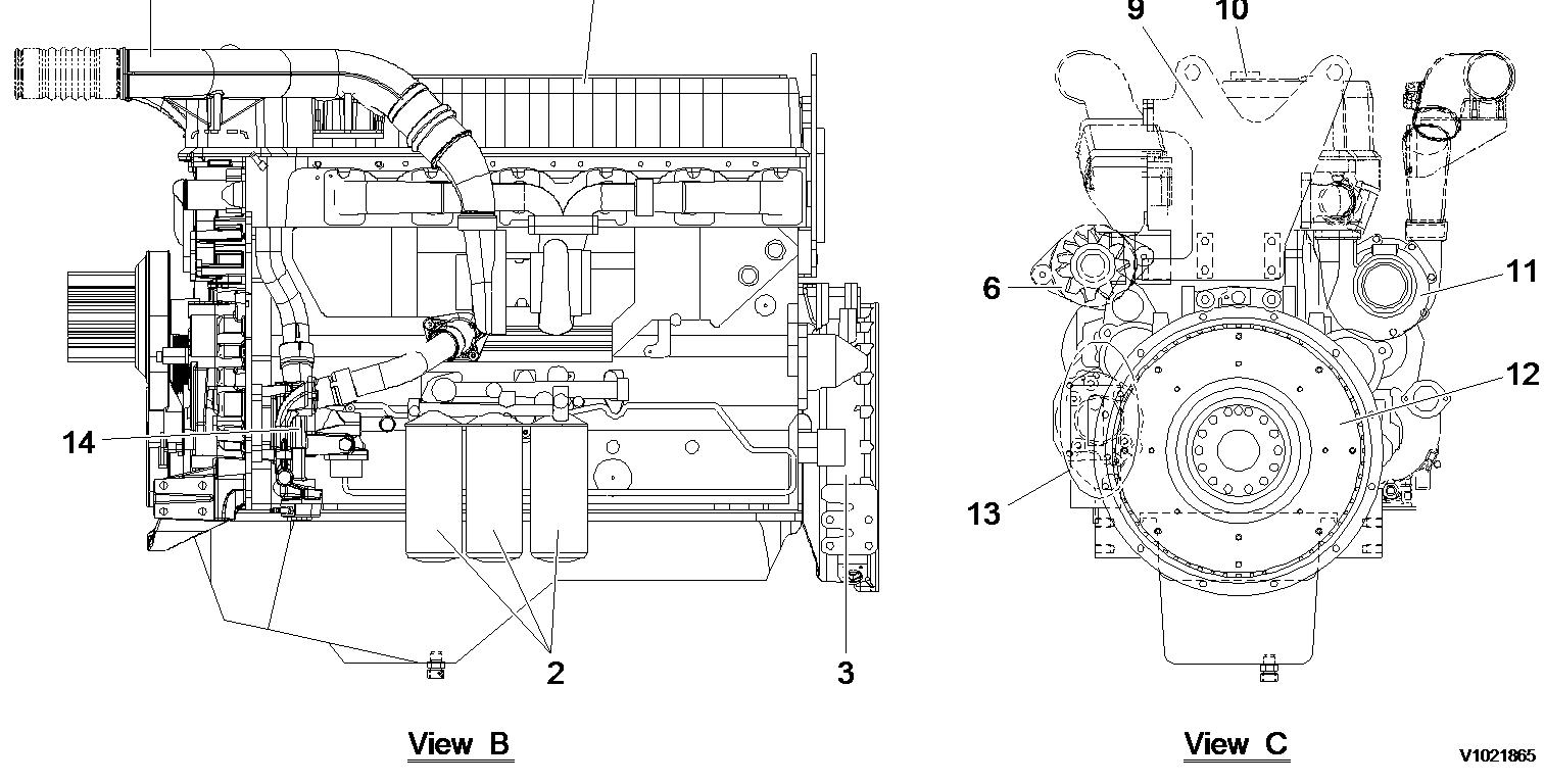 Figure 2
Document Title: Function Group: Information Type: Date: Engine, description 200 Service Information 2015/3/16
Profile:
EXC, EC330B LC [GB]
Go back to Index Page
Engine, description
Machine serial no. EC330B: 10713 ~ , 80001 ~ , EC360B: 12152 ~ , 80001 ~
D12DEBE2 and D12DEBE3 are the model number of the Volvo 12 liter engine.
The engine is a 6-cylinder, 4-stroke, direct injection diesel with a 12 liter cylinder volume, turbocharger, charged air cooler and electronic controlled fuel injection, EMS (Engine Management System).
The serial number of the engine is to be found stamped in the cylinder block on the rear left side.
The cylinder head is of cast iron and manufactured in one piece which is necessary in order to provide stable bearings for the overhead camshaft.
The cylinder liner is sealed against the coolant casing with rubber rings.
The D12DEBE2 and D12DEBE3 have a four-valve system and overhead camshaft.
The engine timing gear transmission is located at the front of the engine on a 10 mm thick steel plate bolted to the cylinder block.
The crankshaft is drop forged and has induction hardened bearing surfaces and fillets.
The engine is force fed lubricated by an oil pump which is gear driven from the engine crankshaft via an intermediate gear
The fuel system for D12DEBE2 and D12DEBE3 have electronic control with unit injectors one for each cylinder and which operate at a very high pressure.
The fuel feed pump is a gear driven type and is driven from the engine timing gear with the same gear.
 Figure 1
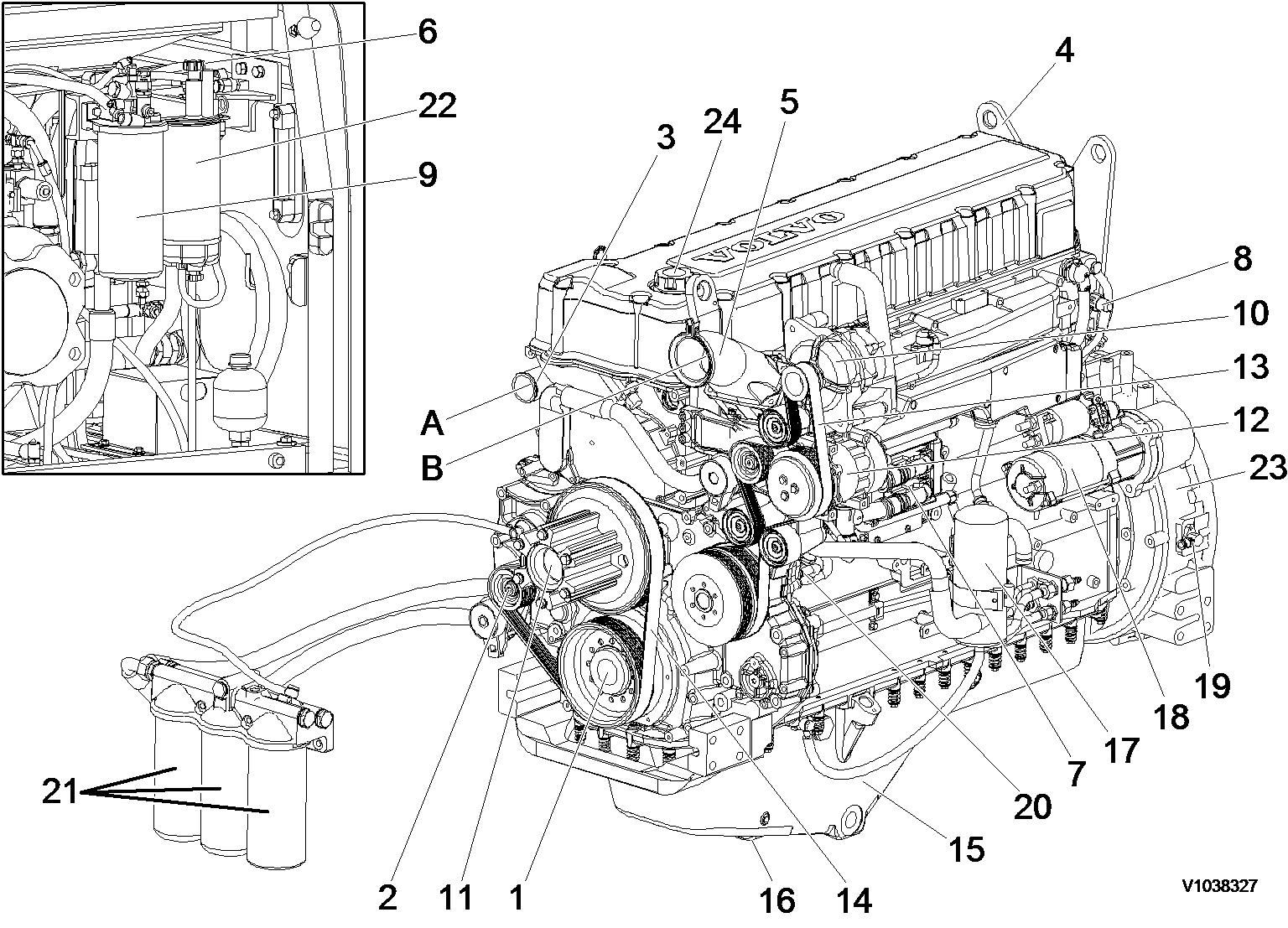 Figure 2
Document Title: Function Group: Information Type:Date:
Valves, adjusting 214 Service Information 2015/3/16

Profile:
EXC, EC330B LC [GB]
Valves, adjusting
Op nbr214-012
88820003Setting tool
9993590Gear wheel
Feeler gauge
WARNING
Risk of burns -stop the diesel engine and allow it to cool down before starting any work.
1.Place the machine in service position B. See 091 Service positions
2.Open the engine hood.
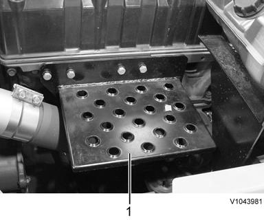
3.Remove step (1).
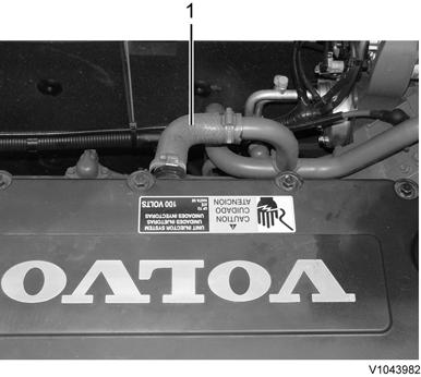
4.Remove crankcase ventilation hose (1).
Removal, crankcase ventilation hose
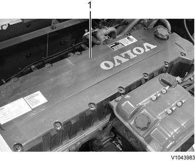
5.Remove valve cover (1).
Adjusting inlet valve
7.Turn the flywheel with tool 9993590 until the nearest dash marking on the camshaft is between the marks on the bearing cap.
NOTE!
The number identifies the cylinder for which both inlet and exhaust valves are in correct position for adjusting.

NOTE!
Cylinder 1 is closest to the engine timing gear.
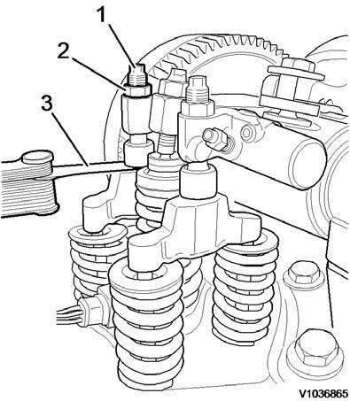
Figure2 Figure3 Removal, valve cover 6.Remove the protective cover on the flywheel housing and install tool 9993590, an extension and a ratchet handle. Figure4 9993590, extension and ratchet handle8.Loosen lock nut (2) on the rocker arm and adjust screw (1) to get the correct valve clearance according to and tighten the lock nut. Tightening torque: see 214 Valve mechanism, double rocker arm
214 Valve mechanism, tightening torques
Adjusting exhaust valve
9.Loosen lock nut (2) on the rocker arm and adjust screw (1) to get the correct valve clearance according to and tighten the lock nut. Tightening torque: see 214 Valve mechanism, double rocker arm
214 Valve mechanism, tightening torques
Figure5 Camshaft marking Figure6 1. 2. 3. Adjusting screw Lock nut Feeler gauge10.Check-measure the valve clearance according to . 214 Valve mechanism, double rocker arm NOTE!
Before checking the double rocker arm's clearance, check that the exhaust valve clearance is correct according to 214 Valve mechanism, double rocker arm
Checking, double rocker arm (IEGR)
11.Loosen the drain nipple and drain air and oil from the double rocker arm.
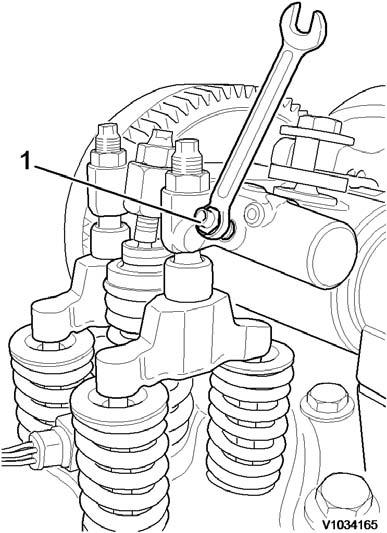
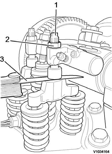 Figure7
1. 2. 3.
Adjusting screw Lock nut Feeler gauge
Figure8
Figure7
1. 2. 3.
Adjusting screw Lock nut Feeler gauge
Figure8
12.Insert the go-side of gauge 88820003 between the double rocker arm's contact surface and the camshaft's basic circle. The go-side must be able to pass between the arm contact surface and the camshaft, if the IEGR-"lift" is not too great.
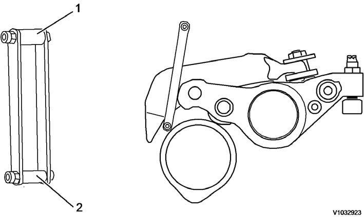
13.Insert the stop-side of 88820003 between the double rocker arm's contact surface and the camshaft'sbasic circle. The stop-side must not be able to pass between the contact arm surface and the camshaft. If itdoes, the IEGR-"lift" is too small.
NOTE!
If the go-side of the gauge passes between the double rocker arm's contact surface and the camshaft's basic circle and if the stop-side does not, the clearance for the double rocker arm is correct. If not, the double rocker arm must be adjusted as follows:
14.Tighten the drain nipple. Tightening torque: see 214 Valve mechanism, tightening torques
15.Adjust the other valves and check-measure the double rocker arm clearance in the same way.
NOTE!
The drain nipple on the double rocker arm must be open during the adjustment procedure.
1.Draining nipple Figure9 Go-and-stop gauge 88820003 1. 2. Stop-side of gauge Go-side of gaugePiston
Adjusting, double rocker arm (IEGR)
16.Keep the camshaft in the same position as when adjusting the valve clearance. Hold piston (7) and loosen lock nut (6) with an Allen head wrench.
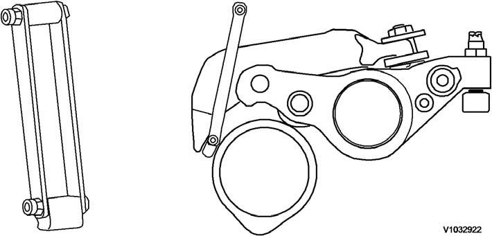
17.Insert adjusting tool 88820003 between the double rocker arm's contact surface and the camshaft's basic circle. Turn piston (7) with an Allen key so that zero clearance is obtained between the double rocker arm, the tool, and the camshaft.
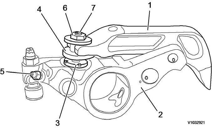
NOTE!
Zero clearance means that the adjusting tool does not slide smoothly between the double rocker arm and the camshaft.
18.Tighten lock nut (6) while firmly holding piston (7) in the correct position. Tightening torque: see 214 Valve mechanism, tightening torques
Figure10 Double rocker arm 1. 2. 3. 4. 5. 6. 7. Follower arm (IEGR-rocker arm) Exhaust rocker arm Stop nut Sleeve Nipple Lock nut Figure11 Adjusting tool 8882000319.Check-measure according to steps 8–12.
20.Install the valve cover, see 211 Valve cover, tightening torque
21.Close the engine hood.
22.Restore the machine to operating condition.
Document Title: Function Group: Information Type:Date: Oil level sensor, changing 217 Service Information 2015/3/16
Profile:
EXC, EC330B LC [GB]
Oil level sensor, changing
Op nbr217-005
9998547Lifting tool
9998648Fixture
9986485Support
WARNING
Risk of burns -stop the diesel engine and allow it to cool down before starting any work.
WARNING
Removal of residual pressure from the circuit must be done prior to any maintenance.
NOTE!
Cable ties and clamps that secure hoses and electrical wiring must be removed and then replaced when installing.
1.Place the machine in the service position B. See 091 Service positions
2.Turn off the battery disconnect switch.
3.Remove the engine. See 210 Engine, removing NOTE!
Place the engine on the work stand.
4.Drain the engine oil into a collection container.
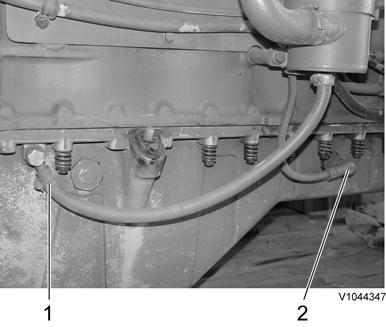
5.Remove engine oil dipstick gauge (1).
6.Remove oil level sensor connector (2) and disconnect crankcase ventilation hose (1) from the oil pan.
Figure1
Removal, oil level sensor connector and crankcase ventilation hose
7.Remove the oil pan mounting screws and then remove the oil pan from the engine block.
Suggest:
If the above button click is invalid.
Please download this document first, and then click the above link to download the complete manual.
Thank you so much for reading

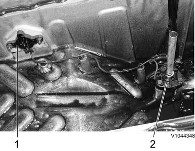
8.Remove oil level/temperature sensor (2) with connector (1) from the oil pan and then replace with anew one.
Removal, oil level/temperature sensor and connector
NOTE!
Do not reuse the O-ring.
NOTE!
Make sure that there is no leakage from the O-ring when assembling.
9.Install the oil pan to the engine block.
10.Fit oil level sensor connector (2) and connect crankcase ventilation hose (1) to the oil pan.
Installation, oil level sensor connector and crankcase ventilation hose
11.Install engine oil dipstick gauge (1).
12.Fill the engine with the specified oil.
NOTE!
Pay attention to the position of direction for cushion and mounting screws (front/rear) when assembling.
13.Install the engine and start the engine. Check for leaks and repair if needed. See 210 Engine, installing
Figure2
Figure3