
Document Title: Function Group: Information Type:
Service Information
Date:
Engine, description 200 Service Information 2014/7/10
Profile:
EXC, EC340D L [GB]
Engine, description
Engines D11H, D13H, and D16H are straight six-cylinder, four-stroke, direct-injected diesel engines. They are equipped with a single variable geometry turbocharger (VGT) and feature cooled external exhaust gas recirculation (EGR). They have charge-air cooling with mechanically actuated electronically controlled unit injectors, controlled by the EMS-system. The engines have a one-piece cylinder head with four valves per cylinder and a single overhead camshaft. Rear-mounted timing gear results in a shorter engine and lighter drivetrain installation. The engine brake for articulated haulers, VEB7, does not have the additional Exhaust Pressure Governor, EPG. Sufficient exhaust back-pressure will be controlled via the VGT. For more information, see:
220 Lubrication system, description
230 Fuel system, description
250 Inlet and exhaust system, description
254 Exhaust Aftertreatment System, description
255 Turbocharger, description
260 Cooling system, description
293 Exhaust Gas Recirculation (EGR), description

For Articulated Haulers:
253 Auxiliary brake (engine braking), description
The cylinders are numbered in sequence, starting farthest from the flywheel. Ignition order: 1-5-3-6-2-4. The engine's rotational direction is counter-clockwise, seen from the flywheel.
Engine identification
Figure 1
Identification plates, D13H
Identification plate 1
A label located on the valve cover showing the engine's component ID-number, serial number, manufacturing site, engine part number, and engine build date, as well as their bar codes. Manufacturing sites:
A = Skövde, Sweden
E = Curitiba, Brazil
F = Flen, Sweden
L = Lyon, France
Identification plate 2
The engine's serial number, part number, and manufacturing site are stamped into the engine's cylinder block.
Identification plate 3
The hardware component number of the Engine Control Unit (ECU) is located on a label on the back of the ECU.

Identification plate 4
The certification label is located on the valve cover as well as the machine's frame.
Automatic Engine Shutdown
This is a function used to automatically shut down the engine after idling for a certain time. The operator is informed and has the opportunity to cancel the function within one minute, either by increasing the engine speed, shifting gear, or by activating the hand throttle.
Engine protection
The ECU contains functionality designed to protect the engine from damage during extreme operating conditions or from further damage when an essential engine component fails. There are several proactive functions, and different applications have different functions activated. The ones that can be activated are:
High coolant temperature
High intake manifold air pressure
High intake manifold air temperature
High oil temperature
Low oil pressure
Low coolant level
High temperature of cooled EGR exhausts after the EGR-cooler
High crankcase pressure
Variable Geometry Turbo valve and position error
High temperature of Smart Remote Actuator
High compressor charge-air temperature (calculated)
High soot load
High differential pressure across Diesel Particulate Filter (DPF)
High exhaust temperature
High ECU temperature
High DPF temperature
Various protective actions such as warning lights, engine torque reduction, engine speed limitation, and vehicle speed limitation may be taken when the above functions reach dangerous levels that may damage the engine. In order to always allow the operator to move a machine away from an unsafe situation, there is a delay of at least 30 seconds before the protective actions (such as forced idle and forced shutdown) are activated after a Key-ON. If the engine has been forced to shutdown or forced to idle due to an active engine protection function, the operator can obtain a 30 second delay by powering down the EMS with a Key-OFF for 7 seconds and then a Key-ON (the EMS is powered down by the Vehicle-ECU (V-ECU) after the ignition key has been in its OFF position for approx. 7 seconds). In addition to the above protective functions, other software functions could request engine protection, such as:
High Altitude (ensures that high compressor charge-air temperature is never reached)
Turbo OverSpeed
Low Coolant Temp
Crank Sensor Failure
Gear Ratio
Regeneration
Warning lights
There are two levels for warning lights, an amber caution light and a red stop light.
The amber light indicates a warning situation
The red light indicates that the vehicle must be stopped.
Engine torque limitation
The engine torque can be limited by the engine protection function. Engine torque limitation is active until the parameter has reached a safe level or until the EMS is powered down.
Forced Idle
The engine can be forced to idle speed by the engine protection function. Forced idle is active until conditions triggering the problem are back within normal working range or the EMS is powered down.
Engine Shutdown
The engine can be forced to shut down after conditions have reached levels that may cause engine failure and the machine speed is below a specified value.
Machine Speed and Engine Speed Limits
The engine protection function can limit the speed of the vehicle and/or the engine's rpm.
Levels of engine protection
Available proactive functions depend not only on the application but also on what level of protection has been activated for the specific machine. Two levels of engine protection are offered, the standard level is Basic protection and the optional level Extended protection. The general difference between basic and extended engine protection is that no active actions such as forced idle and forced shutdown will be taken in basic engine protection (with the exception of crankcase pressure that can cause shutdown in either setup). Warnings will be given to the operator regardless of engine protection level.
Parameters
(FAU) Automatic engine shut off (FAV) Automatic engine shut off, time
(JVL) Injector cylinder 1, calibration E3 Glitch Trim
(JVM) Injector cylinder 2, calibration E3 Glitch Trim
(JVN) Injector cylinder 3, calibration E3 Glitch Trim
(JVO) Injector cylinder 4, calibration E3 Glitch Trim
(JVP) Injector cylinder 5, calibration E3 Glitch Trim
(JVQ) Injector cylinder 6, calibration E3 Glitch Trim
(YA) Idle speed, setting
Supplementary information
200 Component locations
Function check
17030-3 Parameter, programming
Diagnostics
Detailed information about the following relevant warnings and error codes is available under the diagnostics tab.
Component Control unit Message ID EF2112 (ART) PID404 (EXC, WLO) MID128 PID404 EF2117 (ART) PPID55 (WLO, EXC) MID128 PPID55 EF2127 (ART) PPID89 (EXC, WLO) MID128 PPID89 EF2515 (ART) PSID28 (WLO, EXC) MID128 PSID28 EF2525 (ART) PID173 (EXC) SE2510 (WLO) MID128 PID173 SE2202 FX1006 (WLO) MID128 PID175 SE2507 FX1007 (WLO) MID128 PID105 MO2501 MID128 SID27 PPID326 (WLO, EXC) MID128 PPID326 SE2203 MID128 PID100 SE2509 MID128 PID153 SE2516 MID128 PID412 SE2519 MID128 PID81 SE2603 MID128 PID111 SE2606 MID128 PID110
Document Title: Function Group: Information Type: Date: VCADS Pro, Operations 200 Service Information 2014/7/10
Profile:
EXC, EC340D L [GB]
VCADS Pro, Operations
The following VCADS Pro operations are available for function group 2. Operations used when changing or working on components are mandatory.
Tests
Operation
20046-3 Read out engine information
21006-3 Cylinder compression, test
Application
The operation is used to read out the engine emission and engine certificate information when requested by the customer or other interested parties.
Used when there is a suspicion of fault and/or at abnormal values/ readings.
This test indicates if there is any deviation in compression in any cylinder in relation to the other cylinders.
As a first check this operation is both easy and fast to perform instead of a real compression test.
23016-3 Cylinder balancing, test
Used when there is a suspicion of fault and/or at abnormal values/ readings
This test indicates whether any of the injectors deviates too much in the fuel injection so that the engine characteristics are damaged.
23017-3 Feed pressure, inspection
23712-3 Injectors shut off, manual
25410-3 Air pump exhaust aftertreatment, test
Used when there is a suspicion of fault and/or at abnormal values/ readings.
Used when there is a suspicion of fault and/or at abnormal values/ readings.
Used when there is a suspicion of fault and/or at abnormal values/ readings.
25411-3 Burner exhaust aftertreatment, test Used when there is a suspicion of fault and/or at abnormal values/ readings.
25412-3 Components ASU, test
With this sub-test, the functions of the atomiser air valve, the main air valve, the fuel shut-off valve and the fuel pump are checked.
25433-3 Fuel system exhaust aftertreatment, bleeding Used when there is a problem with the tension on the spring in the fuel pressure regulator in the atomization.
25434-3 Atomization unit, fuel pressure, adjust
Used when there is a problem with the tension on the spring in the fuel pressure regulator in the atomization.
25436-3 Atomization unit, air pressure, adjust Used when there is a problem with the tension on the spring in the fuel pressure regulator in the atomization.
25456-3 Exhaust aftertreatment diagnostics Used when there is a suspicion of fault and/or at abnormal values/ readings.
25457-3 Diesel Particulate Filter Service Regeneration
Used when the soot load is over 1.7.
See 254 Exhaust Aftertreatment System, description
Before starting service regeneration check the differential pressure over the diesel particle filter so that it is within stated value according to the service information. This is to make sure that the DPF won’t get damaged by the service regeneration.
After the service regeneration and when the exhaust temperature has stabilized to a normal level check the differential pressure over the DPF again so that it is within stated value according to the service information. This is to determine that the filter has been
Service Information
25460-3 Reset soot and ash load
regenerated correctly and that it is not clogged with ash.
When the diesel particulate filter has been changed, the soot load and the ash load must be reset. The reset is needed to indicate to the system that the filter has been cleaned. The soot load and ash load must only be reset if a clean filter has been installed.
25537-3 Variable geometry turbo function test Used when there is a suspicion of fault and/or at abnormal values/ readings.
27502-3 Engine speed control, test Used when there is a suspicion of fault and/or at abnormal values/ readings.
28407-3 Sensor values, monitoring
Used when there is a suspicion of fault and/or at abnormal values/ readings.
28420-3 Flywheel and camshaft signal, test Used when there is suspicious of faulty signals or faulty connected sensor.
29332-3 Exhaust gas circulation, function test Used when there is a suspicion of fault and/or at abnormal values/ readings.
Calibrations
Operation Application
25536-3 Variable geometry turbo, calibration When changing actuator. See 255 Actuator, variable turbocharger, replacing
Programming
Operation Application
25801-3 MID 233 Control unit, programming When changing ACM or only reprogramming. See 254 ACM, replacing, non-programmed
25802-3 MID 233 Control unit, campaign
28423-3 MID 128 ECU, programming When changing ECU or only reprogramming. See 200 E-ECU, MID 128, changing non-programmed ECU
28422-3 MID 128 ECU, campaign
Document Title: Function Group: Information Type: Date: Engine, identification 200 Service Information 2014/7/10
Profile: EXC, EC340D L [GB]
Engine, identification

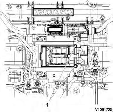
Identification plate 1
A decal with the software's ID-number, the engine's serial number and assembly plant is located on the valve cover to ensure installation of correct ECU on the engine in production. On the back of the ECU, there is a decal indicating its hardware number.
Identification plate 2
Engine designation, serial number, part number and assembly plant are stamped in one field on the engine block's left front edge.
Assembly plants:
A = Skövde, Sweden
E = Curitiba, Brazil
F = Flen, Sweden
L = Lyon, France
Identification plate 3
The engine control unit (ECU) has its component number on a plate on the back.
Identification plate 4
The certification decal is located on the valve cover as well as on the left side of the machine's front frame.
Service Information
Figure 1
Component locations
Title: Function Group: Information Type: Date: Component locations 200 Service Information 2014/7/10 Profile: EXC, EC340D L [GB]
Service Information Document
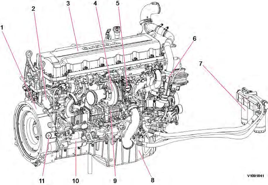
1 Engine,
1 Flywheel housing 7 Engine oil filter 2 P.T.O (Power Take Off) port 8 Oil pan 3 Valve cover 9 EGR cooler 4 Turbocharger 10 Starter motor 5 Turbocharger actuator 11 TDC mark checking port 6 Venturi pipe
Figure
front side

 Figure 2
12 Fan pulley 20 Crankcase ventilation separator 13 Pre-heating coil 21 Oil level sensor 14 Engine oil filling port 22 Alternator 15 Dipstick gauge 23 Air conditioner compressor 16 Crankcase ventilation tube 24 Air pump 17 Air compressor 25 Air pump belt 18 Fuel feed pump 26 Alternator/Compressor belt 19 E-ECU 27 Fan belt
Engine, back side
Document Title:
E-ECU, MID 128, changing non-programmed ECU
Profile:
EXC, EC340D L [GB]
E-ECU, MID 128, changing non-programmed ECU
Op nbr 200-068
1. Park the machine in the service position A, see 091 Service positions
2. Connect the VCADS Pro computer to the machine, and perform operation '28423-3 MID 128 control unit, programming'.

3. When VCADS Pro 'MID 128 ECU, programming' window appears, follow the instructions for replacing E-ECU.

4. Turn OFF battery disconnect switch.
5. Remove the engine hood rear cover screws.
Service Information
Date:
Function Group: Information Type:
200 Service Information 2014/7/10
Figure 1
1. Screws
6. Remove the bracket.
Figure 2
1. Bracket

 2. CNEI connector
7. Disconnect the CNEI connector.
8. Remove the air hose.
Figure 3
9. Remove screws from wire harness clamps, and disconnect the wiring harness connectors from E-ECU.
Figure 4
1. Screws
10. Remove screws fixing the fuel pipe and E-ECU.
Figure 5
1. Screw
2. CNEI connector
7. Disconnect the CNEI connector.
8. Remove the air hose.
Figure 3
9. Remove screws from wire harness clamps, and disconnect the wiring harness connectors from E-ECU.
Figure 4
1. Screws
10. Remove screws fixing the fuel pipe and E-ECU.
Figure 5
1. Screw
2. 3. Pipe Screw
Put the fuel pipe away.
11. Remove 4 screws fixing the E-ECU and replace the E-ECU.
12. Install fuel pipe and screws. Connect wire harness connectors to the E-ECU, and install wire harness clamp screws.
13. Install the air hose and bracket.
14. Install the engine hood rear cover, and the screws.
15. After replacing E-ECU, press OK button of VCADS Pro operation '28423-3 MID 128 control unit, programming'. Now VCADS Pro starts the programming of software and parameters to the new E-ECU.
16. Start the machine and check that no error messages appear.
E-ECU, MID 128, changing pre-programmed
Profile: EXC, EC340D L [GB]
E-ECU, MID 128, changing pre-programmed ECU
Op nbr 200-070
1. Park the machine in the service position A, see 091 Service positions
2. Connect VCADS Pro computer to the machine, and perform operation '17030-2 Parameter, programming'.
3. Use the function 'save all parameters to job card'.
4. Turn OFF battery disconnect switch.
5. Remove the engine hood rear cover screws.
Service Information
Function Group: Information Type: Date:
ECU 200 Service Information 2014/7/10
Document Title:
Figure 1
1. Screws
6. Remove the bracket.
Figure 2
1. 2. Bracket CNEI connector
7. Disconnect the CNEI connector.
8. Remove the air hose.
Figure 3
1. Hose
9. Remove screws from wire harness clamps, and disconnect the wire harness connectors from E-ECU.
Figure 4
1. Screw
10. Remove screws fixing the fuel pipe and E-ECU. Put the fuel pipe away.
Figure 5
1. 2. 3.
Screw Pipe Screw
11. Remove 4 screws fixing the E-ECU and replace the E-ECU.
12. Install the fuel pipe, and screws. Connect wire harness connectors to the E-ECU, and install wire harness clamp screws.
13. Install the air hose and bracket.
14. Install the engine hood rear cover, and the screws.
15. Connect VCADS Pro computer to the machine, and perform operation 17030-2 Parameter, programming'. Now the customer parameters are changed according to the job card saved at step 3.
16. Start the machine and check that no error messages appear.
Document Title: Function Group: Information Type: Date: Engine characteristic curve 210 Service Information 2014/7/10
Profile: EXC, EC340D L [GB]
Engine characteristic curve
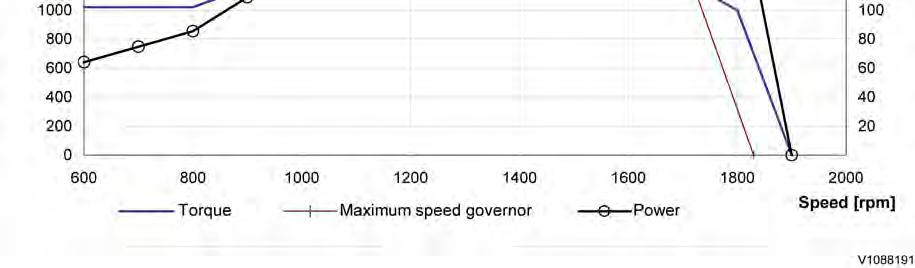
Engine characteristic curve

Engine characteristic curve, SAE J1349 Gross power
Service Information
Figure 1
Document Title: Function Group: Information Type: Date: Engine, removing 210 Service Information 2014/7/10

Profile:
EXC, EC340D L [GB]
Engine, removing
Op nbr 210-070
WARNING
Risk of burns - stop the diesel engine and allow it to cool down before starting any work.
WARNING
Removal of residual pressure from the circuit must be done prior to any maintenance.
NOTE!
Cable ties and clamps that secure hoses and electrical wiring must be removed and then replaced when installing components.
NOTE!
Disconnected hoses, lines and connections must be plugged. Oil that drains from hoses, lines and connections should be collected in a container.
1. Place the machine in the service position B. See091 Service positions

2. Turn off the battery disconnect switch.
3. Drain the coolant in a collection container. See 261 Coolant, changing
4. Open the engine hood and remove the bracket from the cowl frame.
5. Remove the DPF hood, radiator hood and the rear cover
Service Information
Figure 1
1. Bracket

 Figure 2
1. 2. 3. 4.
DPF hood Engine hood Engine room rear cover Radiator hood
6. Remove the engine room cowl frame with the engine hood using a lifting device.
7. Disconnect the wire harness connector and the hoses.
Figure 3
1. 2. Wire harness connector Hose
8. Remove the expansion tank with the bracket.
9. Remove the clamps and then remove the charge air cooler tube and the radiator hoses.
Figure 2
1. 2. 3. 4.
DPF hood Engine hood Engine room rear cover Radiator hood
6. Remove the engine room cowl frame with the engine hood using a lifting device.
7. Disconnect the wire harness connector and the hoses.
Figure 3
1. 2. Wire harness connector Hose
8. Remove the expansion tank with the bracket.
9. Remove the clamps and then remove the charge air cooler tube and the radiator hoses.


 Figure 4
1. 2. 3.
Charge air cooler upper tube Radiator upper hose Radiator breathing hose
10. Remove the engine room under covers.
Figure 5
1. Engine room under cover
11. Release the pressure in the air compressed system by pushing up a valve on the air tank.
Figure 6
1. Release valve
Figure 4
1. 2. 3.
Charge air cooler upper tube Radiator upper hose Radiator breathing hose
10. Remove the engine room under covers.
Figure 5
1. Engine room under cover
11. Release the pressure in the air compressed system by pushing up a valve on the air tank.
Figure 6
1. Release valve
12.


 2. Air tank
Disconnect the radiator under hose and remove the charge air cooler under tube.
Figure 7
1. 2. Radiator under hose Charge air cooler under tube
13. Remove the screws and separate the shroud from the radiator assembly. Move the shroud to the engine side.
Figure 8
1. 2. Shroud Radiator assembly
14. Remove the main pump. See 913 Hydraulic pump, replacing
15. Remove pump room covers.
2. Air tank
Disconnect the radiator under hose and remove the charge air cooler under tube.
Figure 7
1. 2. Radiator under hose Charge air cooler under tube
13. Remove the screws and separate the shroud from the radiator assembly. Move the shroud to the engine side.
Figure 8
1. 2. Shroud Radiator assembly
14. Remove the main pump. See 913 Hydraulic pump, replacing
15. Remove pump room covers.
Suggest:
If the above button click is invalid.
Please download this document first, and then click the above link to download the complete manual.
Thank you so much for reading

16. Disconnect the hoses, remove the mounting screws and the engine PTO pump. NOTE!


Plug the P.T.O (Power take off) hole to protect from foreign substances.
17.
NOTE!
Ports must be plugged after disassembling hoses.
18.
Figure 9 1. Pump room cover Figure 10 1. 2. 3. Hose Screw Engine PTO pump Disconnect the fuel line hoses (4 pcs). Figure 11 1. Hose Disconnect the hose connected to the air cooler and the compressor head.