A New Idea for BEIC Library in Milan
PART 3 - Structure & Materials Part
LOOP OF KNOWLEDGE

A New Idea for BEIC Library in Milan
PART 3 - Structure & Materials Part
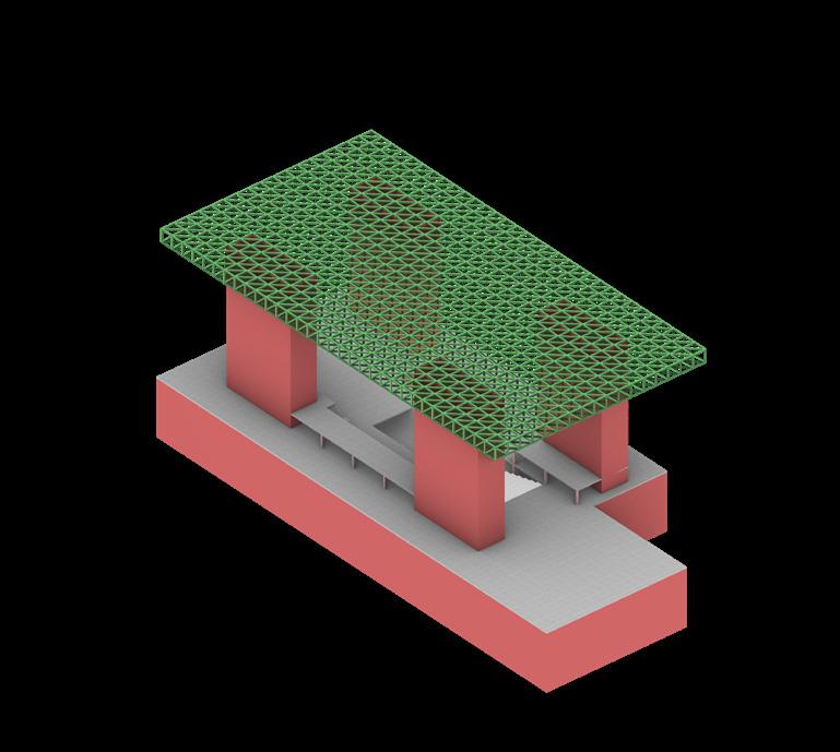
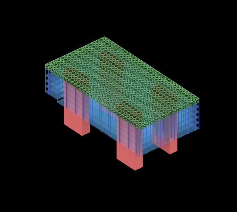
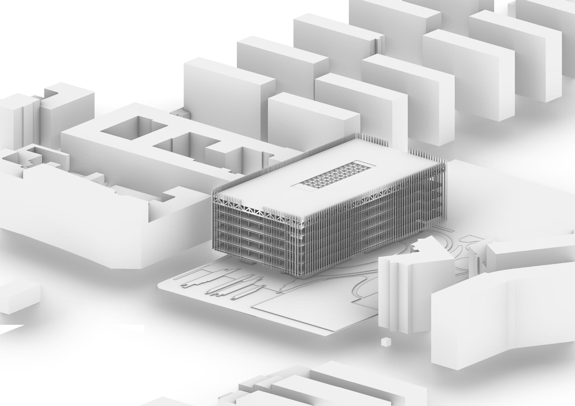
The upper library block is suspended and disjoint from the ground floor, which has a RC foundation. The suspended structure is supported by a sturdy steel hat frame plate with a grid of 3m by 3m by 3.5m. This steel structure, represented by the HEM 700 profile, takes on the role of support, its precise geometry reflecting the architectural goal.
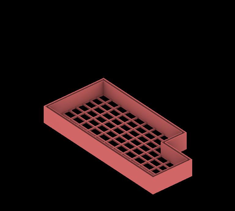
1 Foundation Foundation beams 800mm x 1000mm
Double wall system for basement.
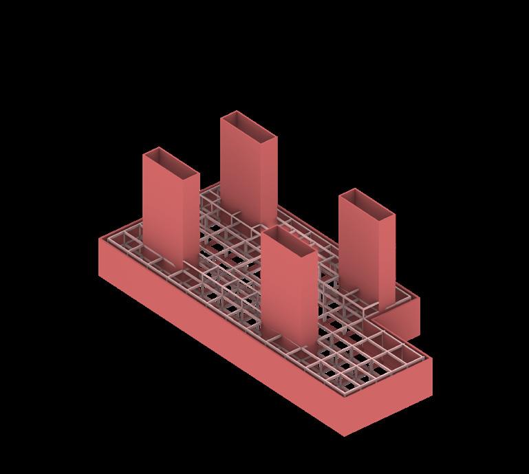
2 Traditional RC frame
Reinforced concrete casting on-site.
Typical columns 400mm x 600mm; Typical beams 400mm x 400mm.
Large span columns 400mm x 1000mm; Large span beams 400mm x 800mm.
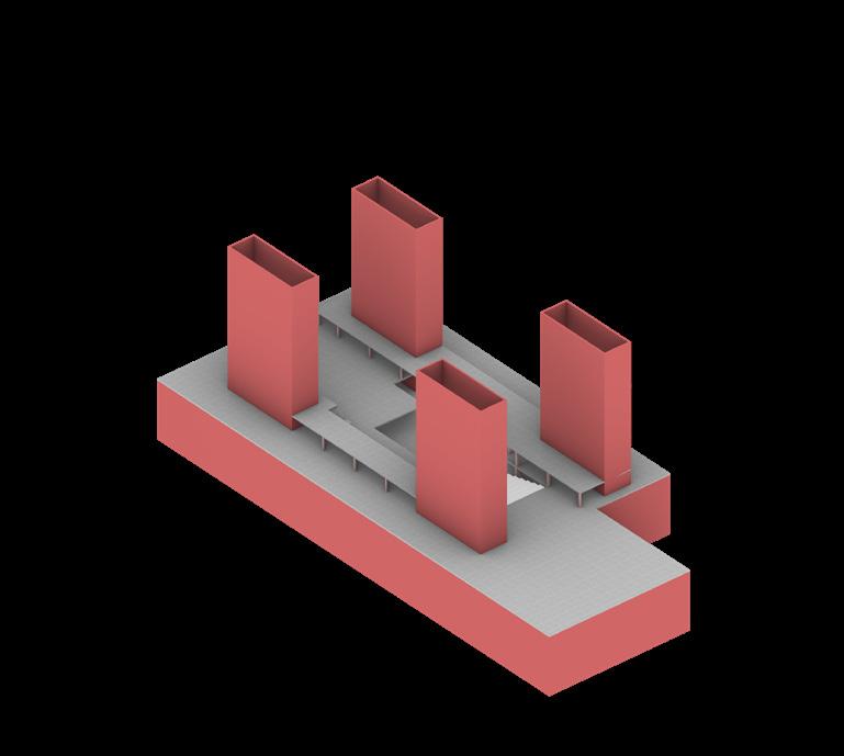
3 Cores
Reinforced concrete casting on-site. Shear walls thickness= 400mm.
4 Hat Frame Plate
Steel truss plate in grid of 3m*3m*3.5m, formed with HEM 700, supported by the four cores
5 Suspended Columns
Hollow circular steel columns are applied.
Standard suspended column Ø219.1mm th. 17.5mm
6 Suspended floors and beams
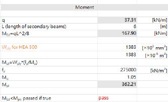
Upper (library) floors are suspended, with the gird of 6m*9m.
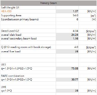
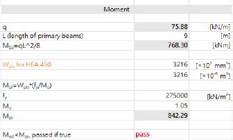
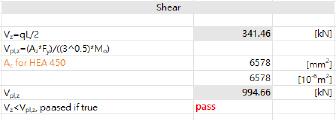
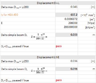
Standard primary beam type: HEA 450
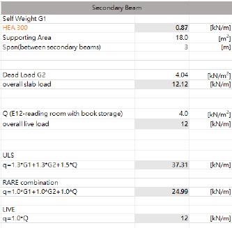
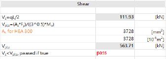
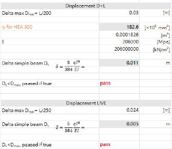
Standard secondary beam type: HEA 300
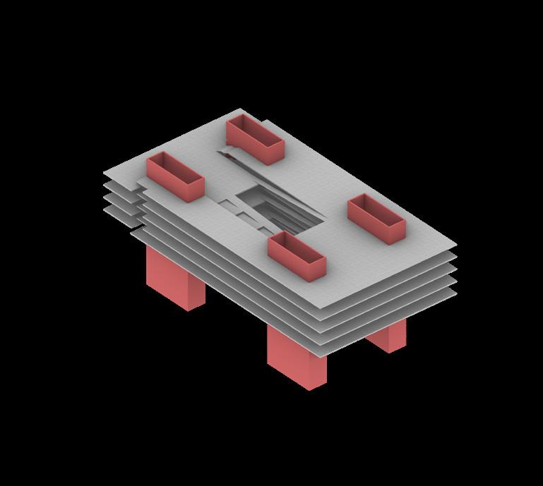
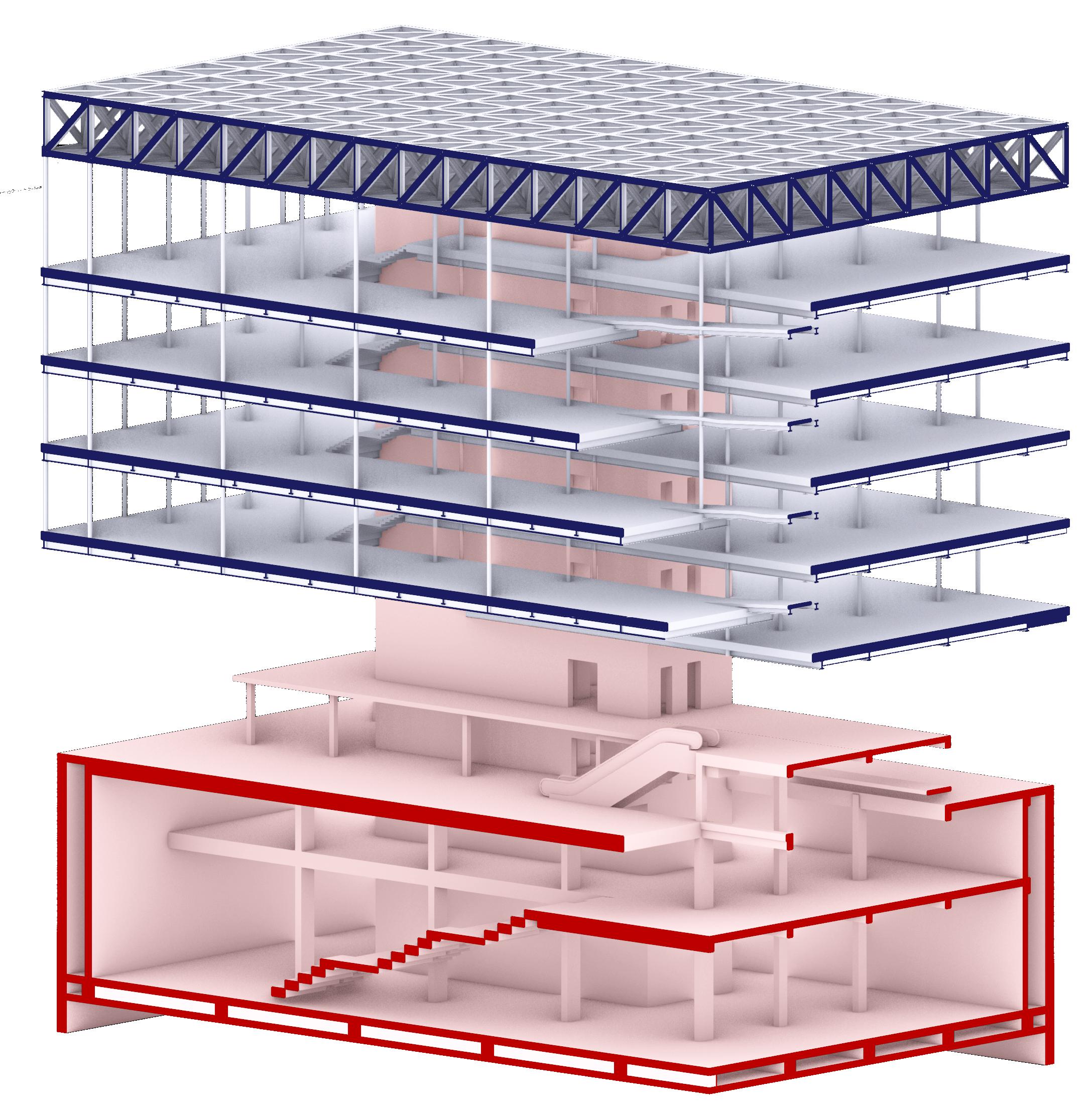
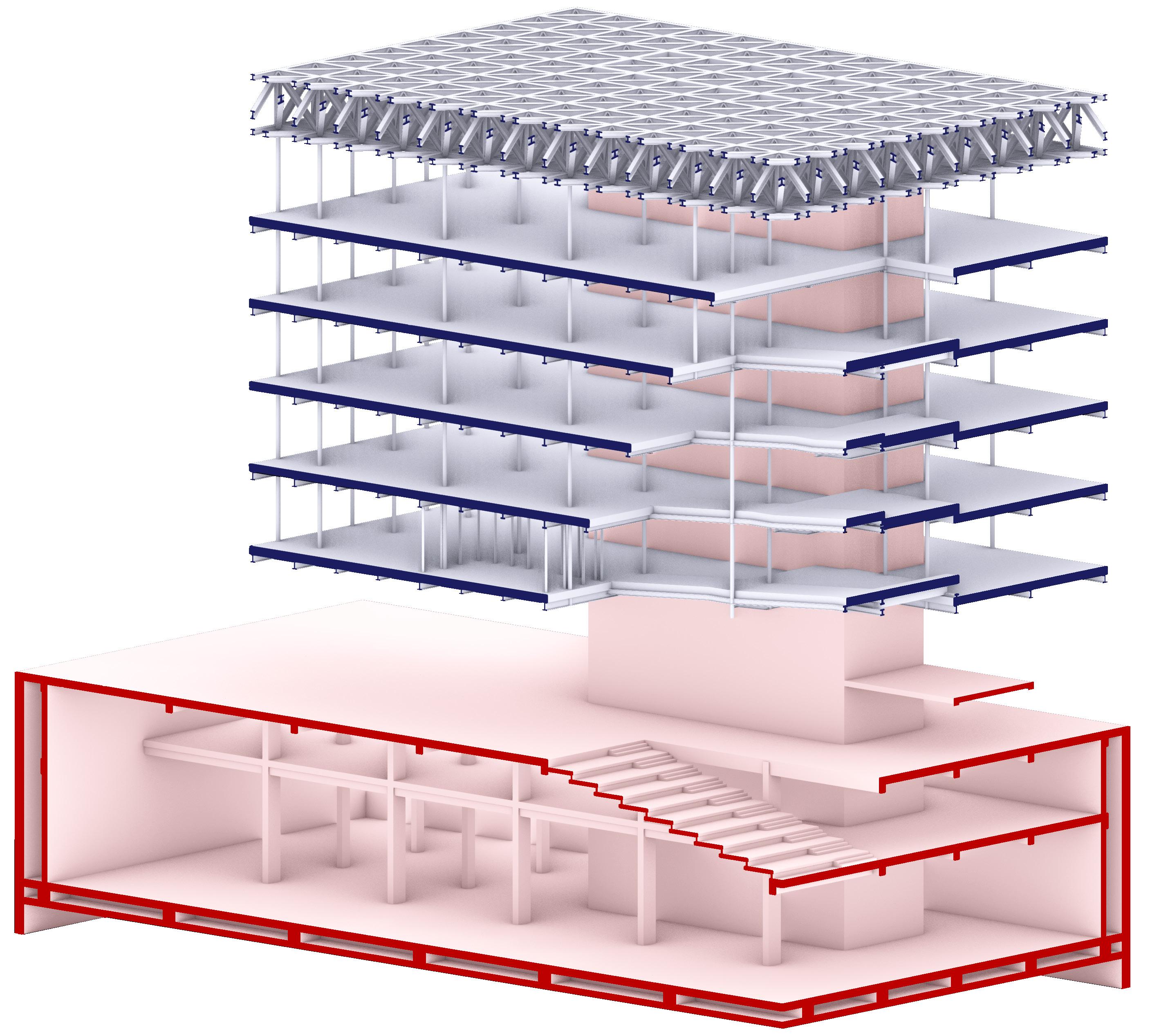
7 Explode Diagram
Showing the three parts of the structure: Frame plate, suspended floors, foundation and RC part, and suspended facades attaching to both the suspended floors and frame plate.
Suspended Floors&Facade: Top-down Construction

Four reinforced concrete cores, each with a thickness of 400 millimeters, are anchored to this hat truss plate. These cores support the suspended structure’s weight as well as its architectural resolve, resulting in a play between form and function that resonates throughout the entire structure.
Cables are suspended from the hat frame plate. These cables, infusing a certain lightness into the spatial character, form an important part of the structure. The library levels intersecting these structures are inside a grid of 6 meters by 9 meters.
The stability of the façade is integrated into the structure of the hat frame plate. The façade maintains its stability by links, demonstrating the successful collaboration between structural competence and aesthetic aim.
The relationship between sunken plaza and the central void is aligned to each other.
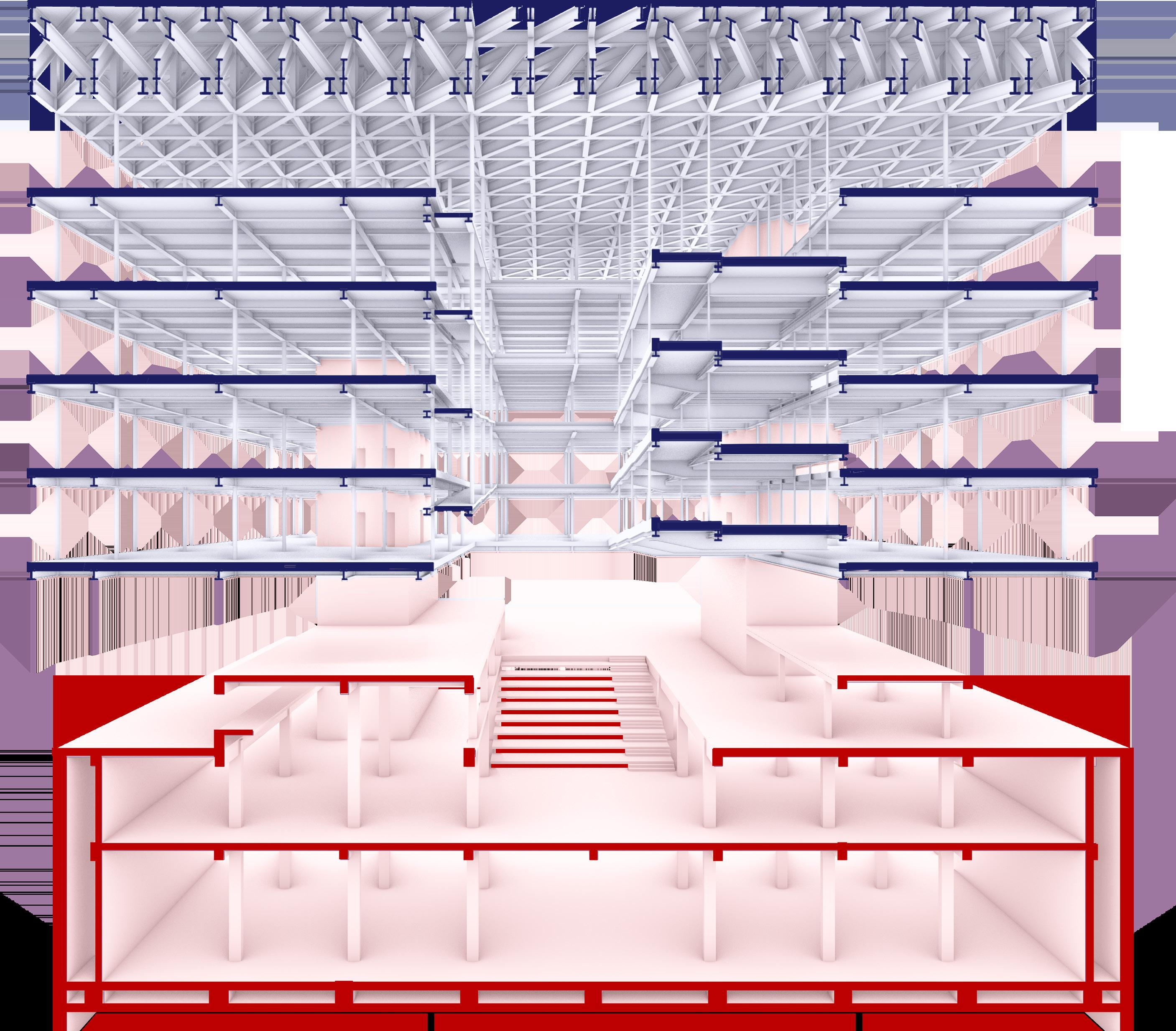
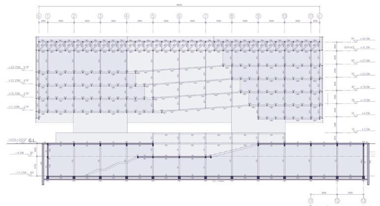
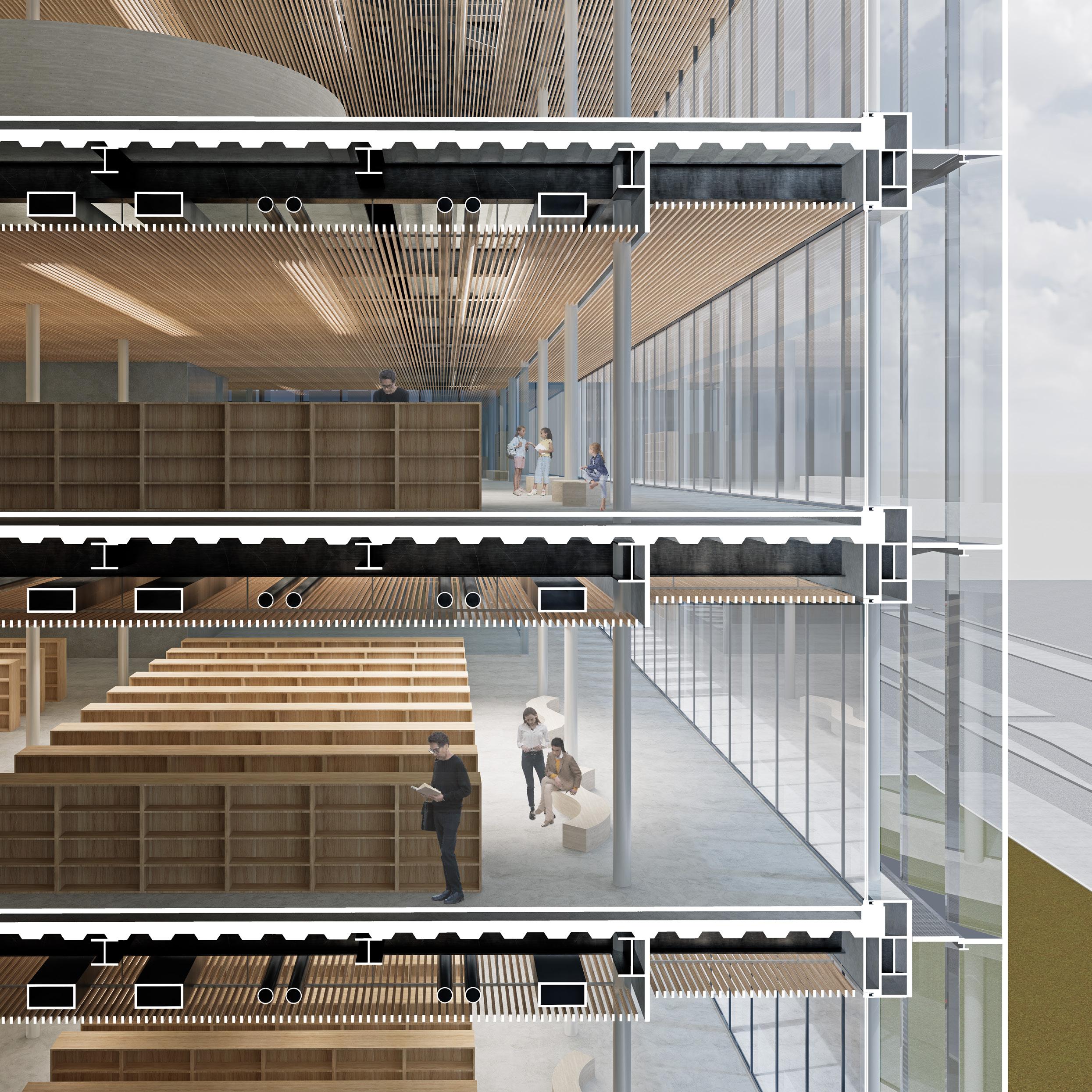
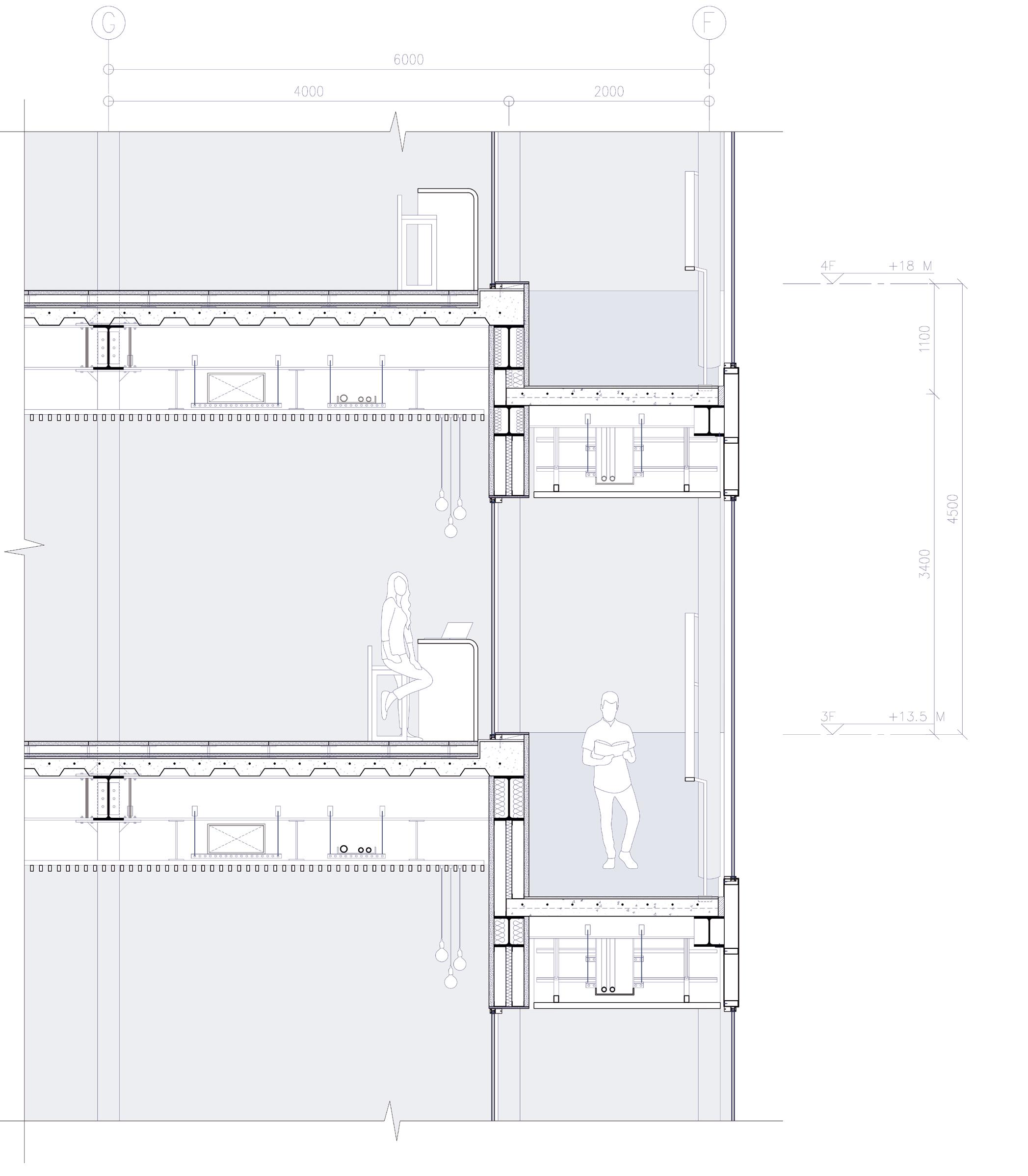
The sections represent the functioning of the structure together. It defines the building’s purpose and suspends and sustains the structure physically using steel, concrete, and cables.
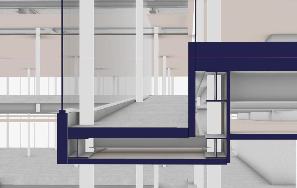
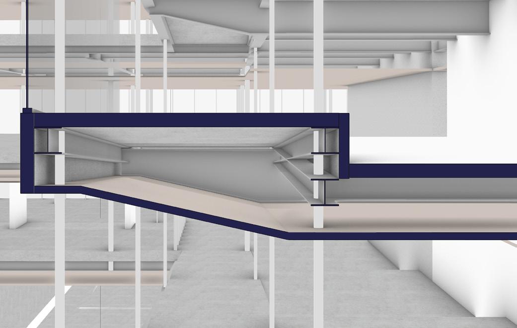
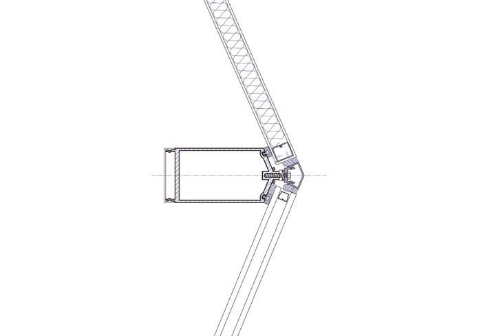
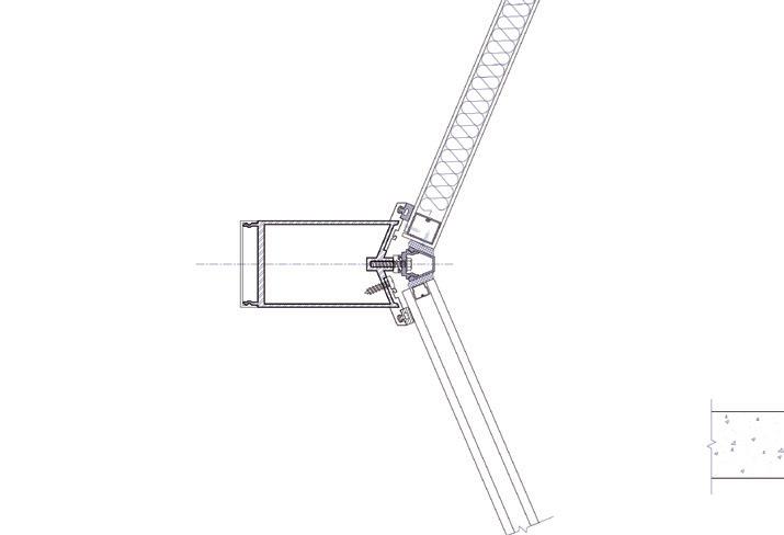
The structural detail that joins the beam of the ramp to the structural beams of the floor is a crucial point in ensuring the physical integrity of the building and merging of engineering with architectural choices we have taken.
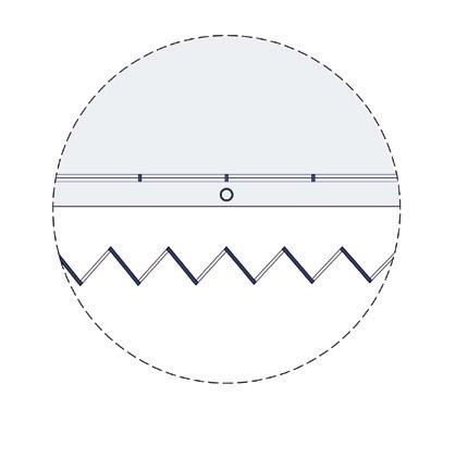
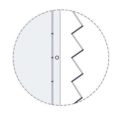
1 Configuration of the beams, flooring and ceiling. Showing the intersection of ramps and floors.
2 Configuration of the beams, flooring and ceiling. Showing the intersection of ramps and floors.
3 Key plan for the iso
4 The Isometric Diagram of North-West Corner
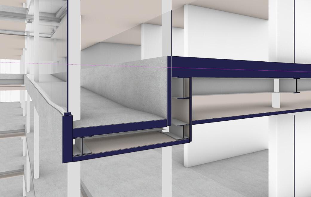
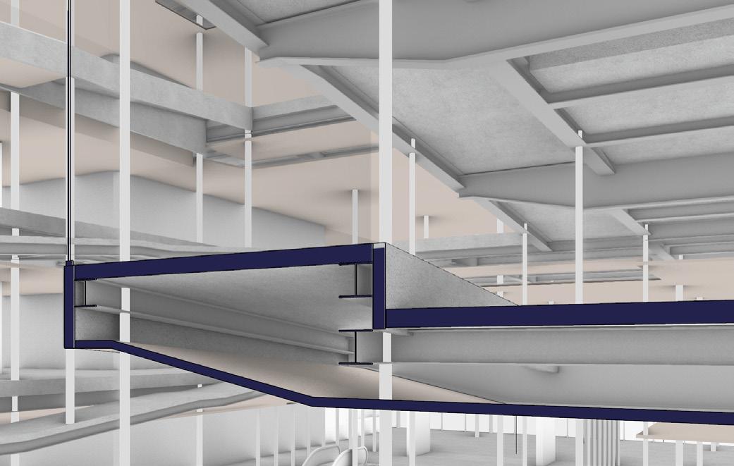
1 Configuration of the beams, flooring and ceiling. Showing the intersection of ramps and floors.
2 Configuration of the beams, flooring and ceiling. Showing the intersection of ramps and floors.
3 Key plan for the iso
4 The Isometric Diagram of South-East Corner
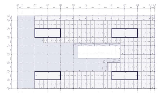
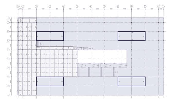
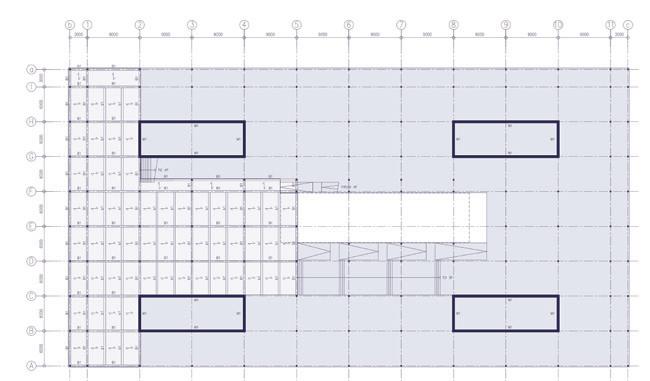
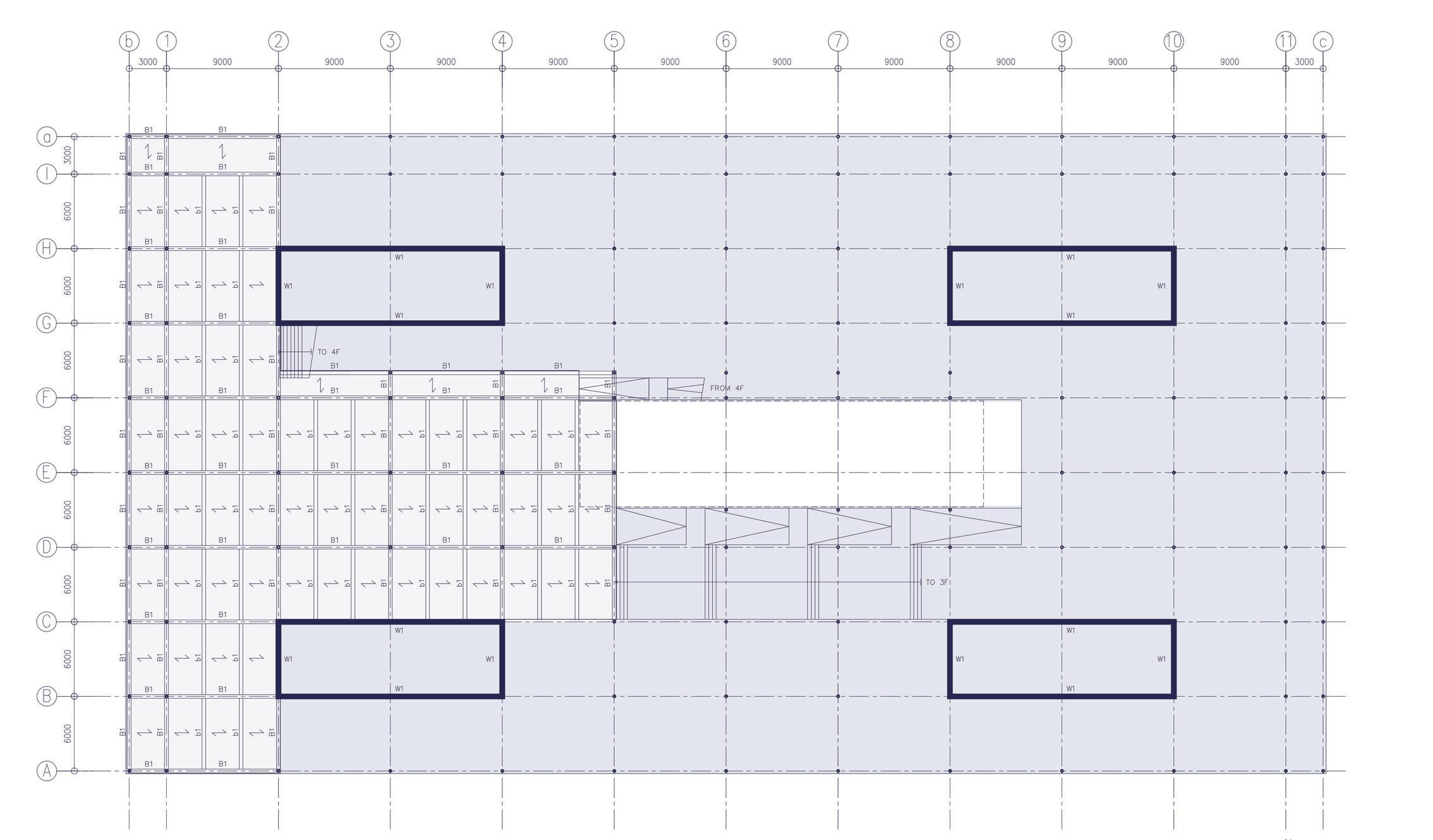
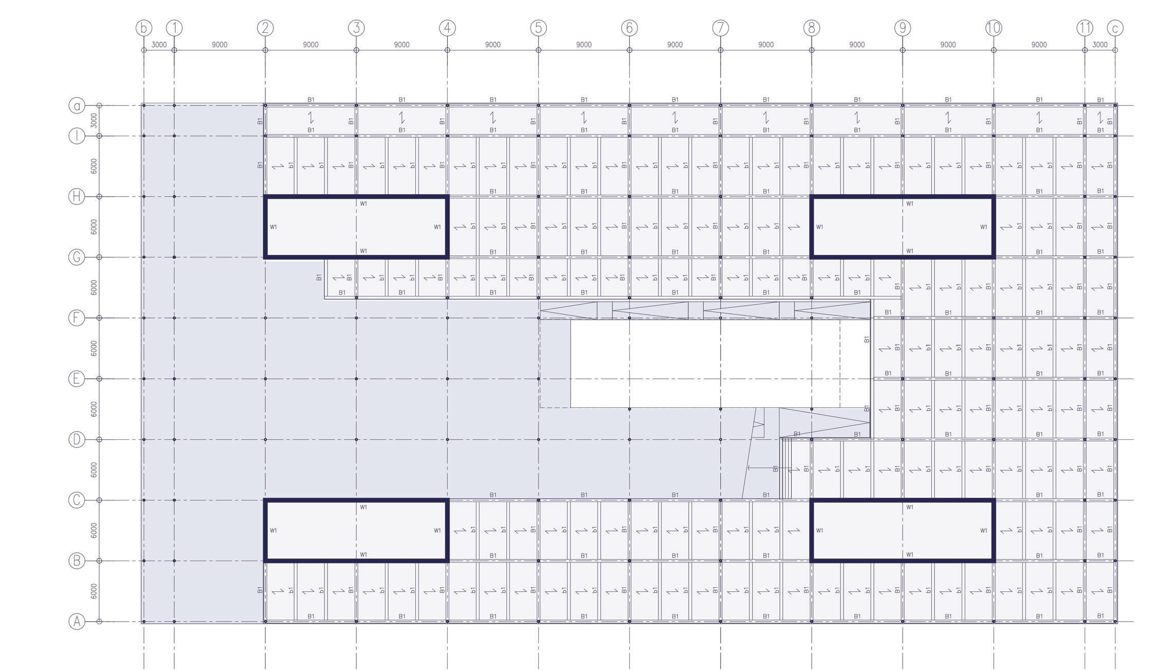
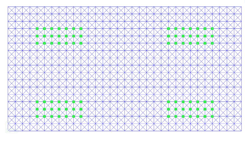
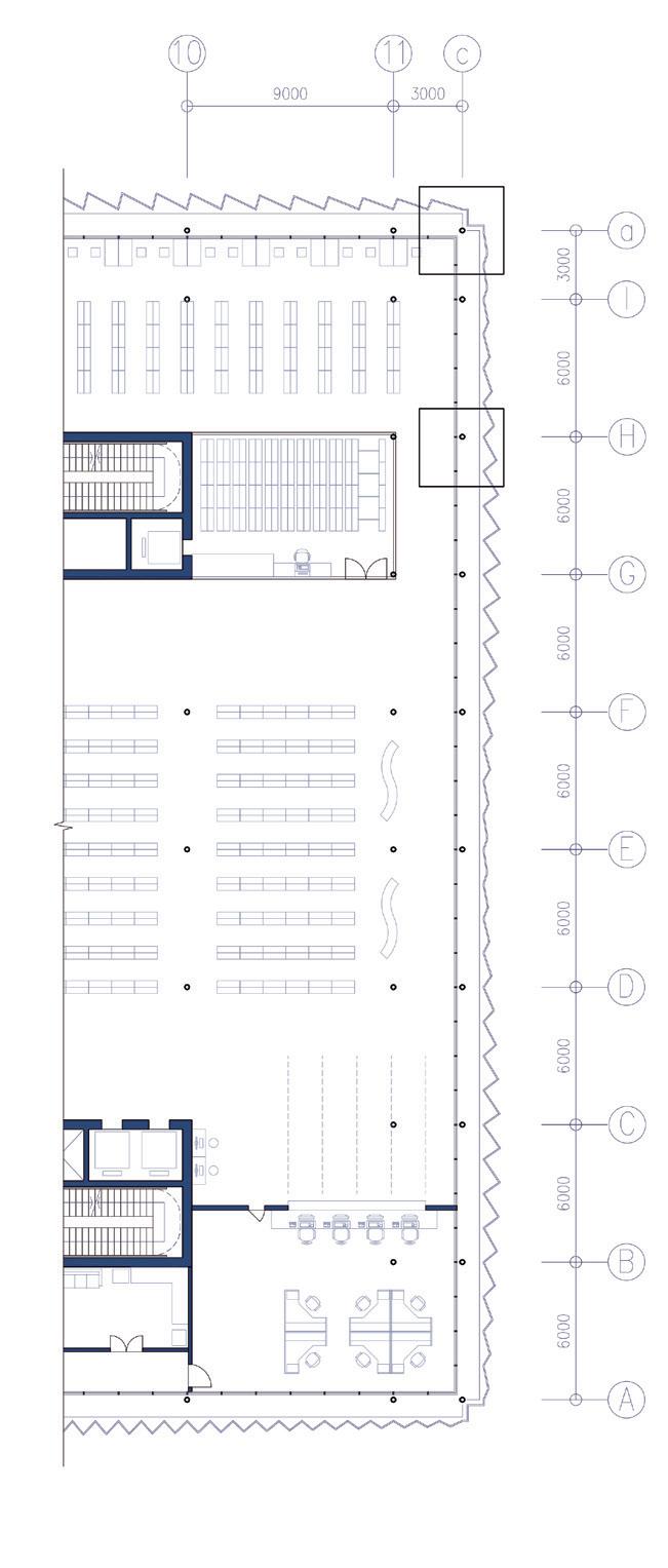
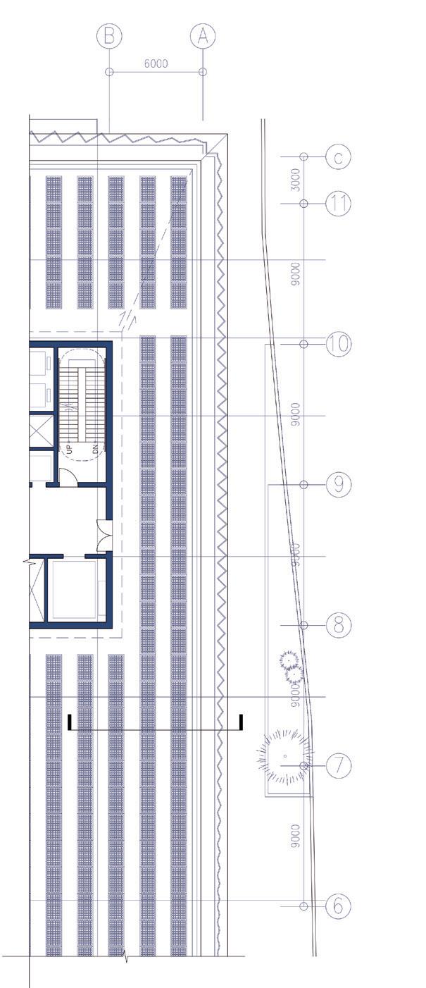
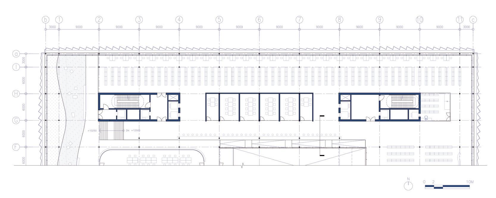
This plan depicts a typical floor configuration level of the building for both the split floor and regular floor. It showcases the arrangement of primary and secondary beams that play a crucial role in distributing the structural loads.
1 Typical Structure Plan: Split Floor 3.5F
2 Typical Structure Plan: Library Floor 3F
3 Key section for the floor plans dim. unit: mm
Calculation Area for C1
The beam-column connection is a crucial aspect of steel framing in structural design. Use of steel plates to connect the beam to the column is done. These plates are typically thicker than the members they are connecting and are designed to withstand the tension forces transferred between the two members important for our design.
1 Beam-Column Connection (plan view)
2 Beam-Column Connection (section a)
3 Beam-Column Connection (section a)
4 Key plan for the structural section
5 Structural section on Frame E dim. unit: mm

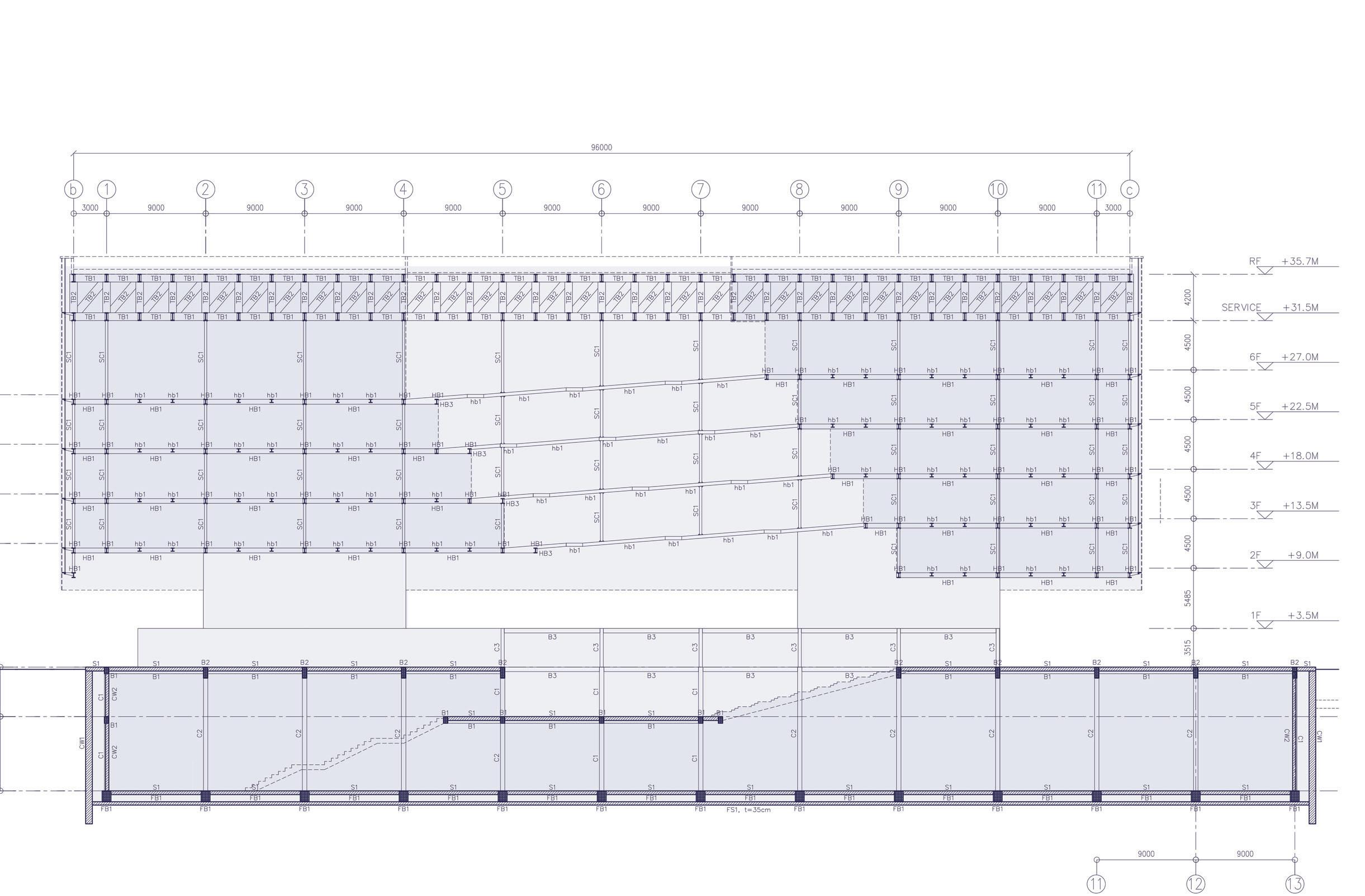
Foundation + Ground Floor:
Slab
S1= 20 cm
FS1= 35 cm
Shear Wall
CW1= 60cm
CW2=40cm
Beam(u=mm)
B1= 400*400
B2= 400*800
B3= 300*400
FB1= 800*1000
Column(u=mm)
C1= 400*600
C2= 400*1000
C3= 300*300
Suspended Library Floors: Beam(u=mm)
HB1= HEA 450, S235
Hb1= HEA 300, S235
TB1= HEM 750, S355
TB2= HEM 750, S355
Column(u=mm)
Ø219.1mm th. 17.5mm
Structural calculations for a complex building with a suspended hat truss design involve a comprehensive analysis of various factors to ensure safety and stability.
After a series of verifying the loads, which involves load analysis, load distribution, structural elements design choice, stress analysis, buckling and deflection analysis all the while ensuring that the design complies with relevant building codes and standards for structural safety and performance, in our case the Eurocode.
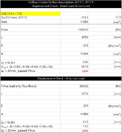
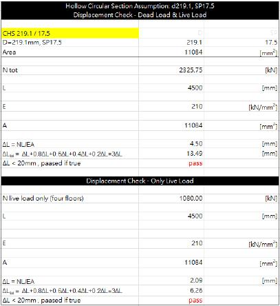
Since our major structure is suspended, our main concern for vertical elements is its elongation. After verifying the loads, hollow circular steel columns are applied.
Standard suspended column type: Ø219.1mm th. 17.5mm.
1
2
3
dim.
Suspended Column C1
‘Tuni A Sezione Circolare’
Ø219.1mm th. 17.5mm
Evaluation of Elongation -1
Area C1-1
Top floor: 6.75 m
Total: 4 floors
Evaluation of Elongation -2
Area C1-2
Top floor: 4.5 m
Total: 5 floors
HEA 450, S275 steel class 440x300x11.5x21
HEA 300, S275 steel class 290x300x8.5x14
 Primary Beam B1
Secondary Beam b1
Primary Beam B1
Secondary Beam b1
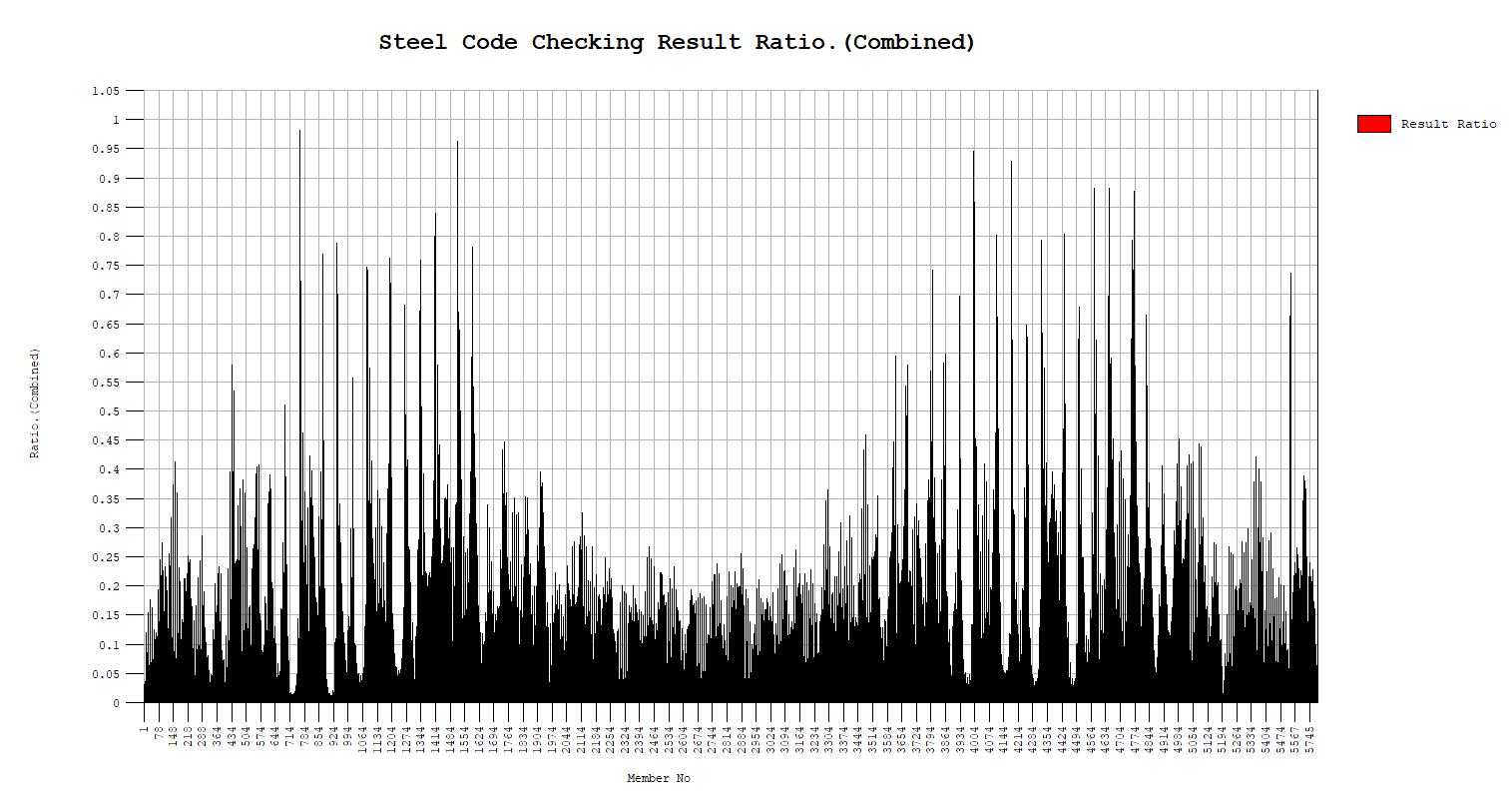
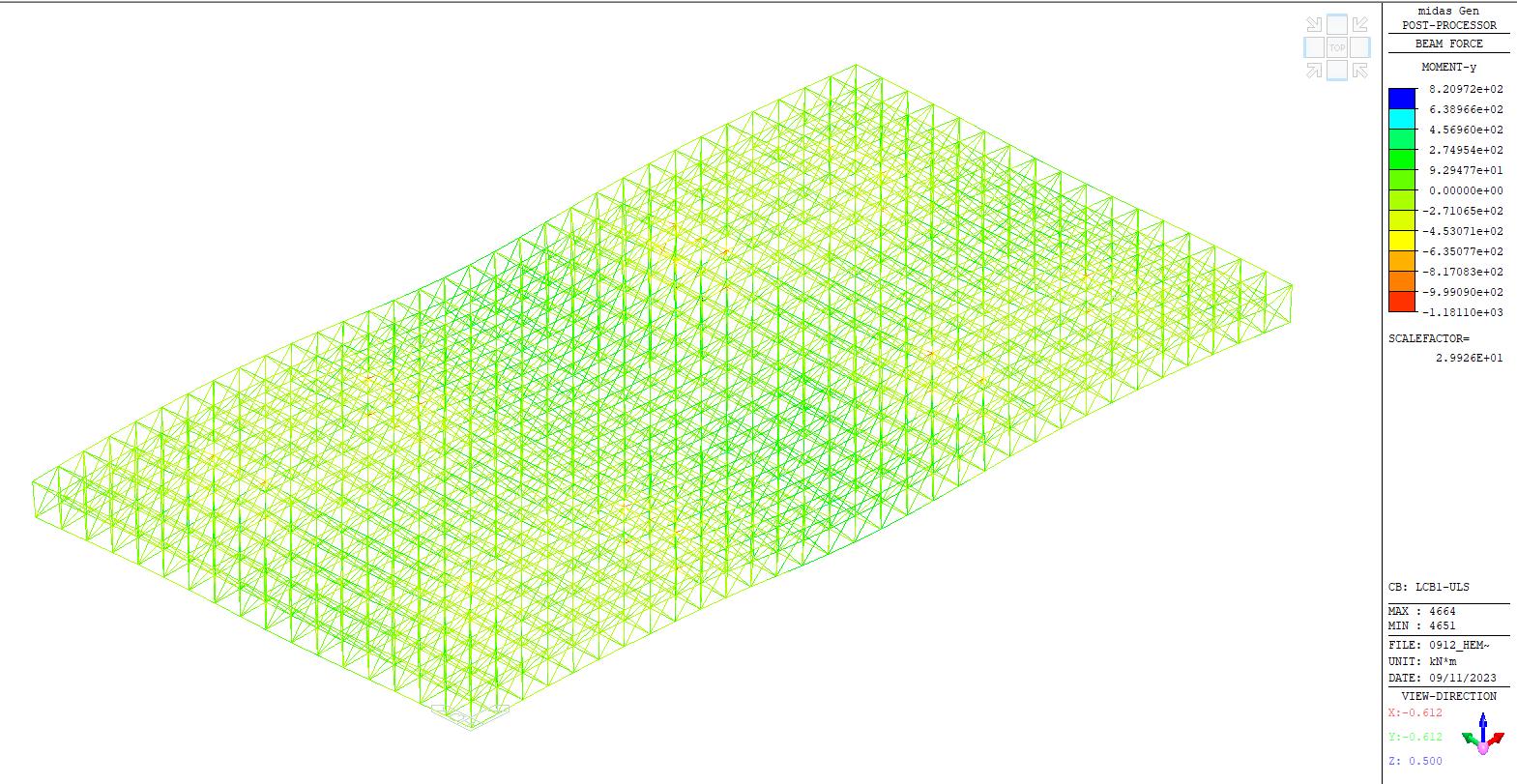
The check of MIDAS software to analyze the hat truss within our building’s structural framework is paramount due to the complex nature of our truss, especially within a suspended building.
It allows for a thorough analysis of the hat truss’ performance. Because of its analytical techniques, it is possible to calculate essential structural behaviors such as stresses, deformations, load distributions, and others accurately.
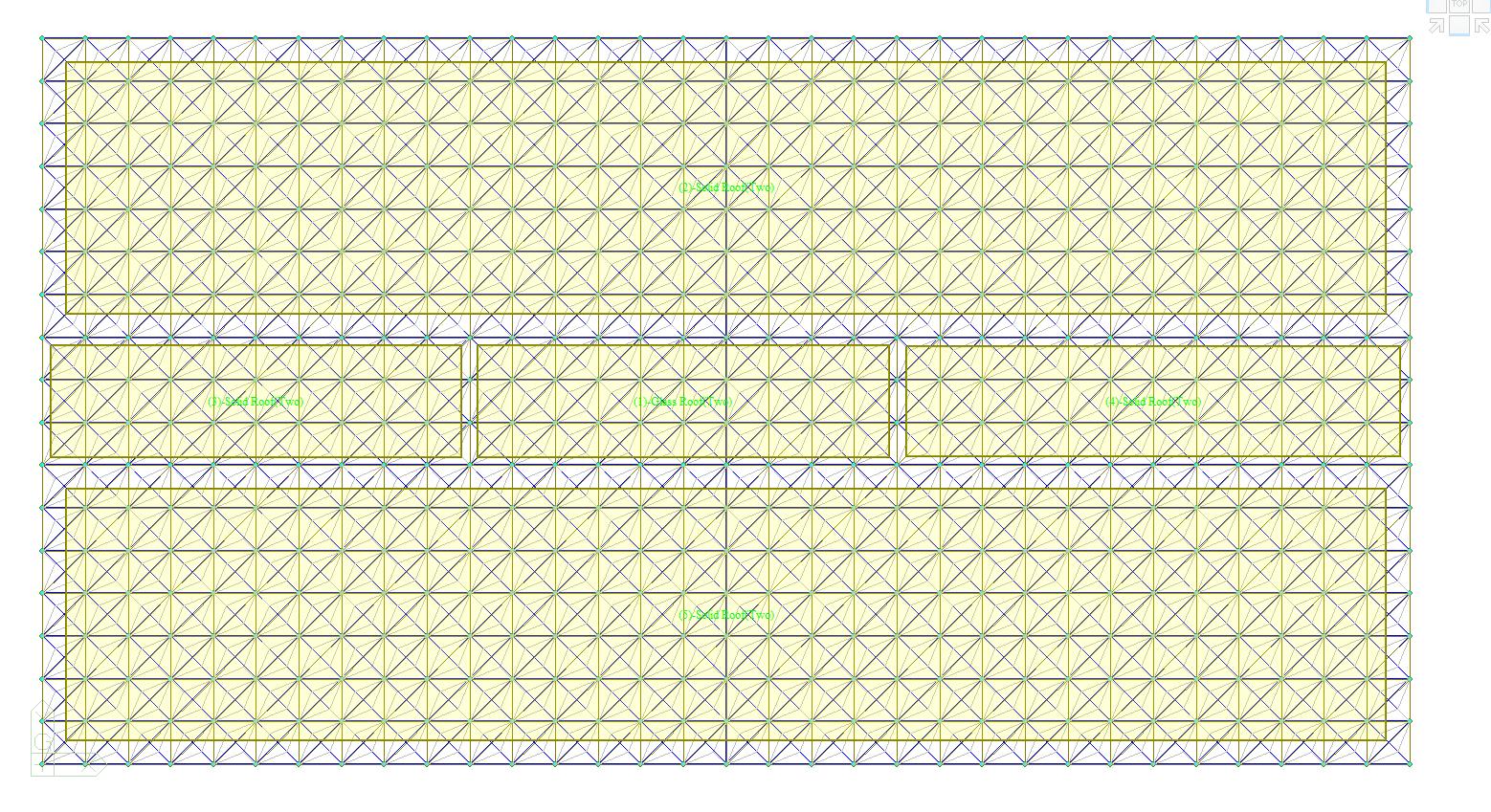
Frame-like Plate of 3.5M Height
Gripd: 3M
STEP 1:
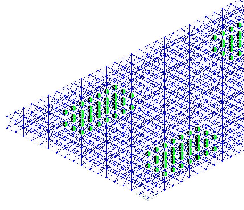
 Nodal DL from Suspended Columns
Roof DL 1,Slab= -9.31kN/m2
2,Skylight= -0.39kN/m2n
Nodal LL from Suspended Columns
Nodal DL from Suspended Columns
Roof DL 1,Slab= -9.31kN/m2
2,Skylight= -0.39kN/m2n
Nodal LL from Suspended Columns
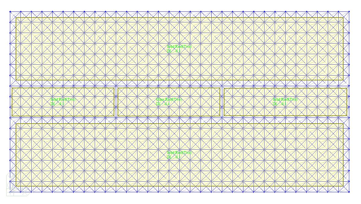
The material used for this frame-like plate is HEM 700, made of S355 steel. It has a geometry with a 3m x 3m grid and a height of 3.5 meters. Around the core of the structure, we’ve applied constraints to ensure stability. This includes two layers of support with a “Fix D-ALL” configuration, allowing rotation. We’ve maintained the beam end release conditions. Various load combinations used:
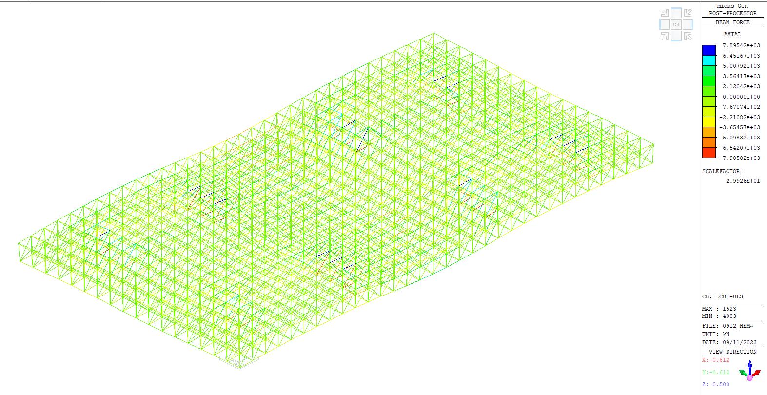
LCB1-ULS: Ultimate Limit State, which includes 1.3 x Dead Load (DL) and 1.5 x Live Load (LL).
LCB2SLS: Serviceability Limit State, with 1.0 x DL and 1.0 x LL.
1.
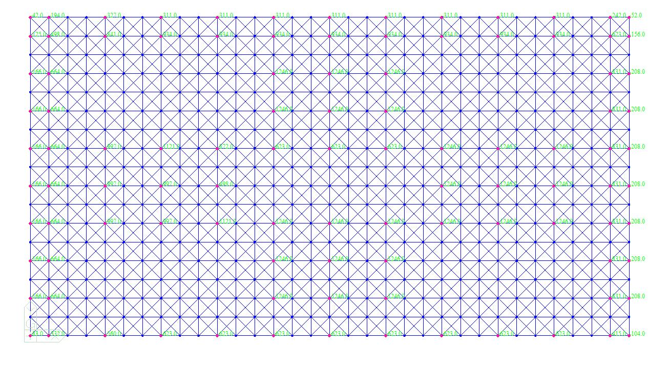
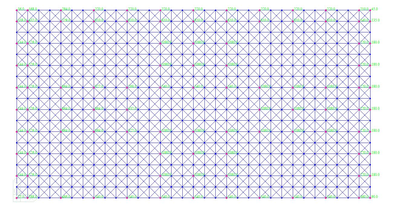
Our findings indicate that the maximum allowable displacement at the SLS is 3.5 centimeters. This means that under normal service conditions, the structure should not deflect beyond this limit to maintain its intended functionality and safety.
2.
1, POS:1/2) Fzz = -477.41 (LCB: 1, POS:I)
3.
4.
MAX[ M_Edy/Mny_Rd, M_Edz/Mnz_Rd ]
R.BiM = (M_Edy/Mny_Rd)^Alpha + (M_Edz/Mnz_Rd)^Beta
R.byN = N_Ed/(A*fy/Gamma_M0), R.byM = M_Edy/My_Rd + M_Edz/Mz_Rd
Rc.LT1 = N_Ed/(Xiy*A*fy/Gamma_M1)
Rb.LT1 = (kyy*M_Edy)/(Xi_LT*Wply*fy/Gamma_M1) + (kyz*M_Edz)/(Wplz*fy/Gamma_M1)
Rc.LT2 = N_Ed/(Xiz*A*fy/Gamma_M1)
Rb.LT2 = (Kzy*M_Edy)/(Xi_LT*Wply*fy/Gamma_M1) + (Kzz*M_Edz)/(Wplz*fy/Gamma_M1)
Rmax
Max. approx. 3.5 cm
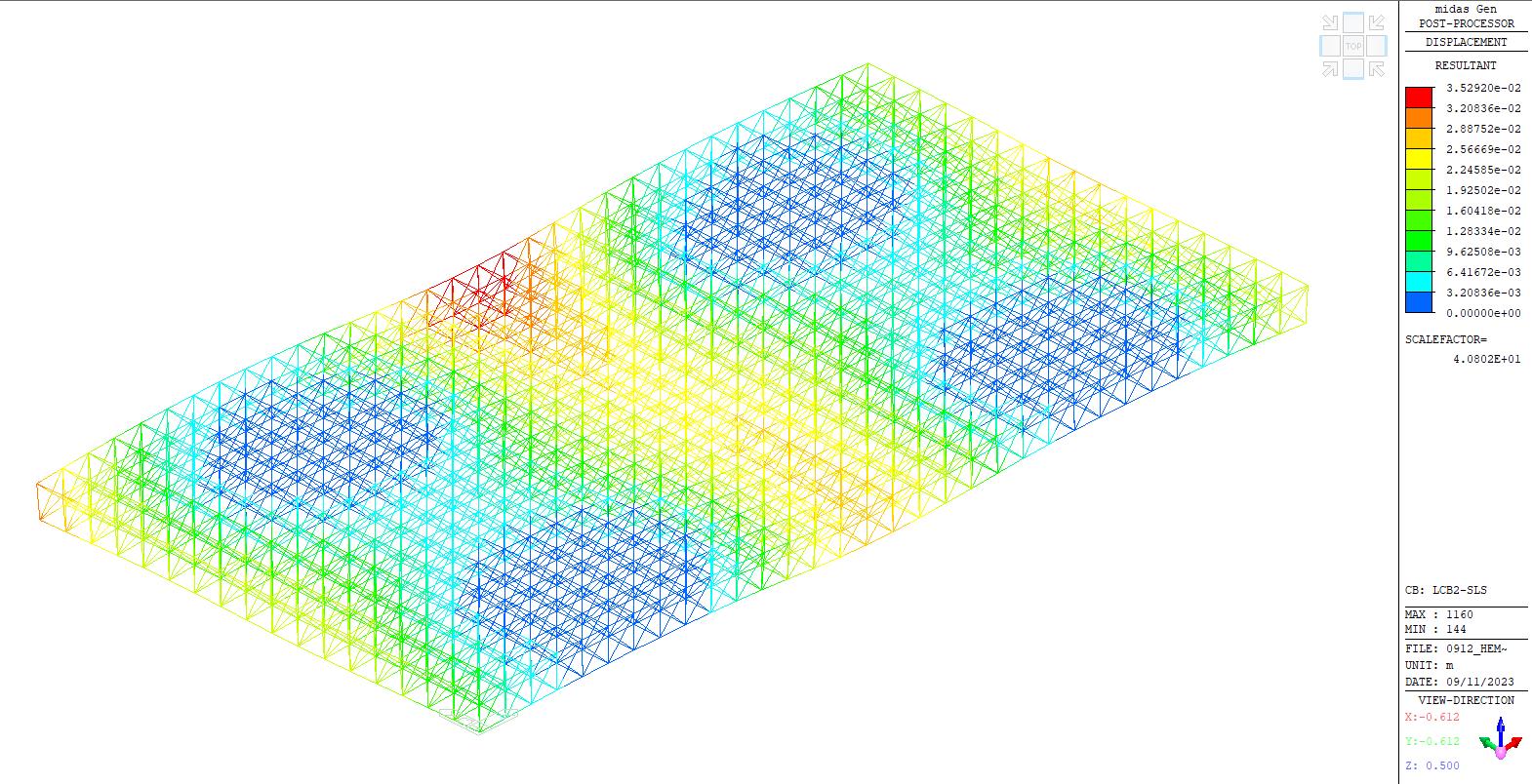

 SLS-Combined displacement
ULS-Shear Force-z
ULS-Moment-y
ULS-Axial Force
SLS-Combined displacement
ULS-Shear Force-z
ULS-Moment-y
ULS-Axial Force
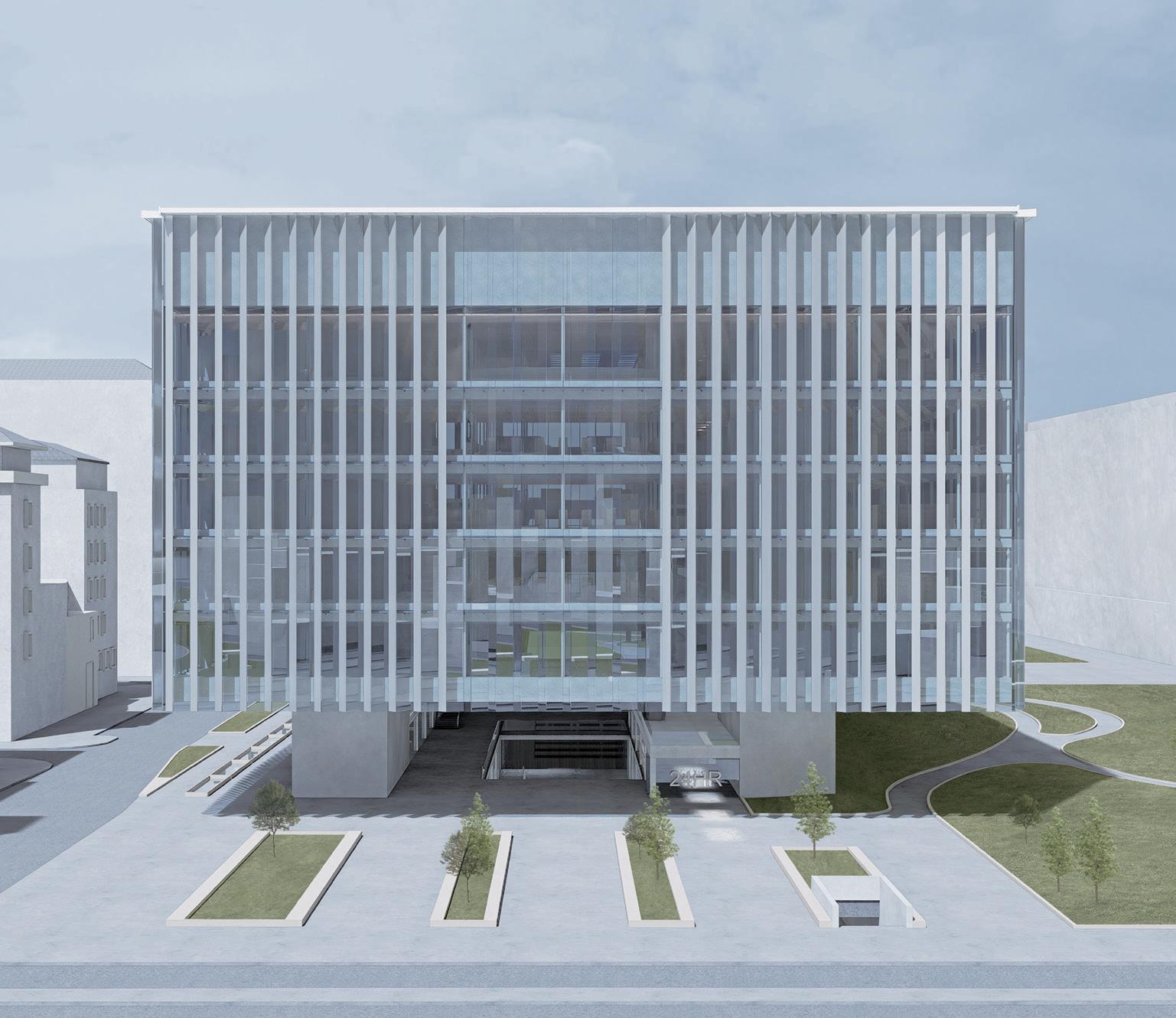
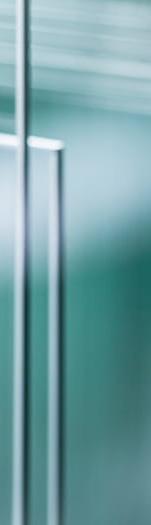
Our façade follows the principle of ‘Bekleidung,’ which is the concept of cladding, where the façade is covered with another layer that could be functional or also purely aesthetical. It enhanced the overall appearance and building efficiency of the exterior.
This cladding not only shades the building from environmental conditions but it contributes to its visual character and identity. It also helps create an air cavity, which helps in insulation to regulate the interior temperature and reduce energy consumption.
The module is created through the intersection of glass and aluminum panels, each with a specific function and relationship to its surroundings. The aluminum panel and its glass counterpart come together in a module where the angle of its joinery plays an important role in deciding how much light is to be let inside the building.
The parametric architecture controls the facade composition by grasshopper, where each exterior face is dependent on its contextual and functional spaces within and around the building.
The length of each module remains constant, while the panels assume a variable angle, a responsive adaptation designed to the solar radiation of the context. This parametric pattern of angles orchestrates the influx of sunlight, bringing interior spaces with the desired luminance.
1 Exploded Diagram
2 Diagrams of the idea of Facade: ‘Bekleidung’ (cladding as disguise)
3 Sectional Perspective
Column/ Structure
Facade
1500 mm
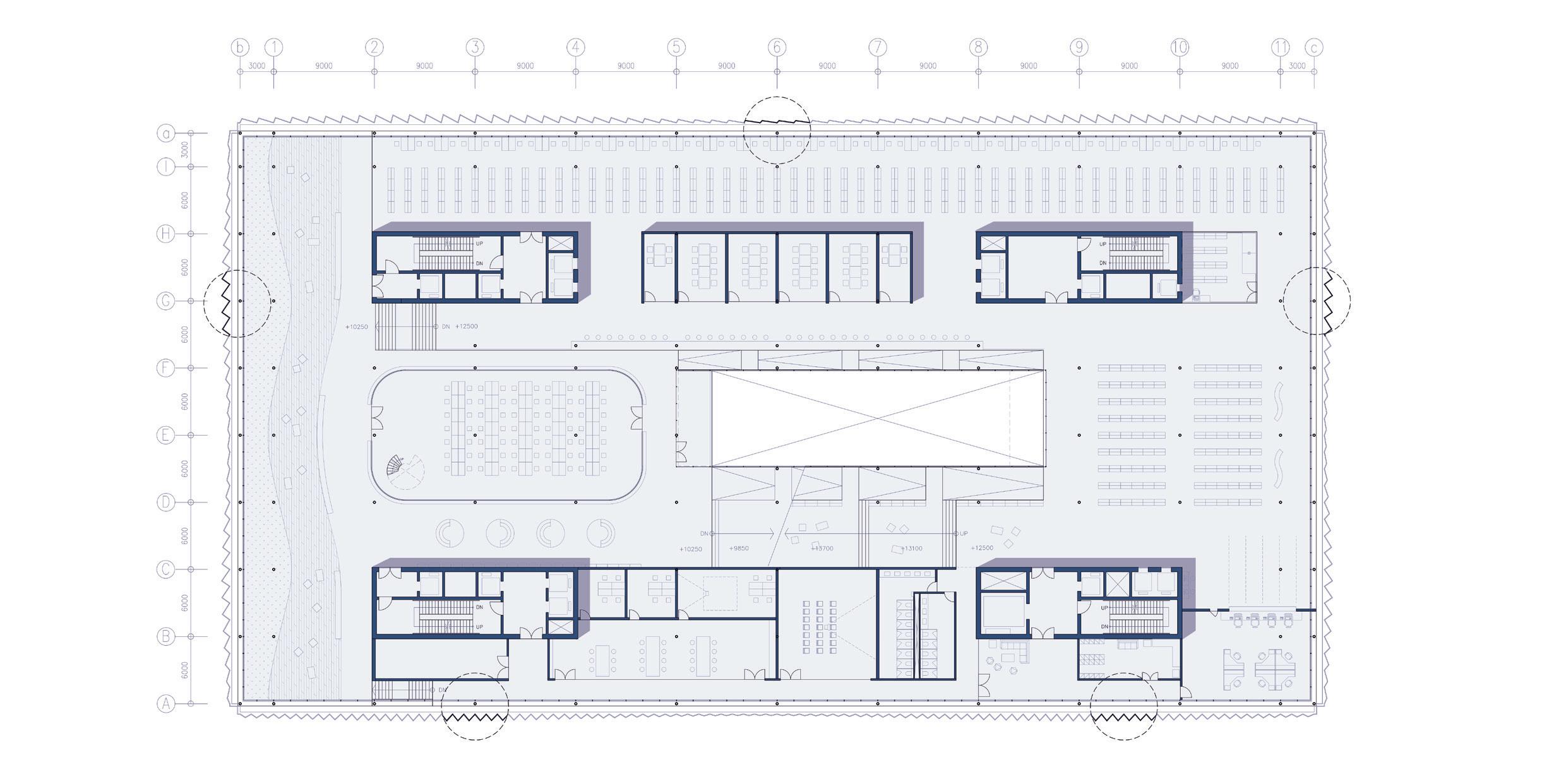
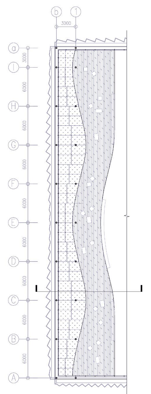
Facade unit’s width have been fixed as 1500mm to align the support framework to the structural grid.The ‘serrated facade’ is the outer profile of the library building, which is important for sun protection and daylight intake. Considering the different sunlight conditions of the four facades and the internal functions, the serration angle (α) is varied through parametric sinusoidal mapping. It not only creates an elegant street view visual effect but also significantly improves the indoor light environment.
Step 1:
Set geometry:
Facade Area
Dominant Sun shading/ take-in direction
Step 2:
Match function: We use SIN mapping to find appropriate pattern according to interior uses
Step 3:
Adaption: Manually adapt the corner fillet. Also different strategies on the four sides.
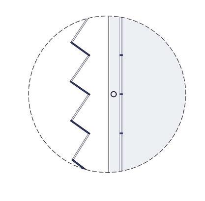
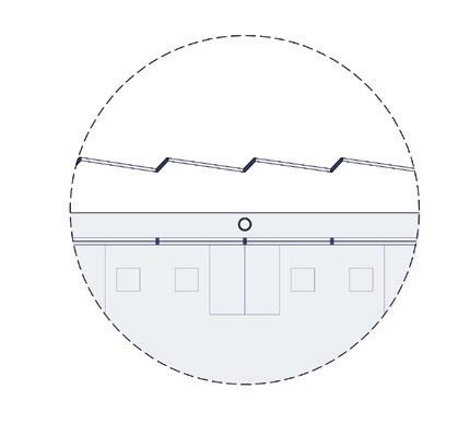
1 Development steps
2 Details of the ‘serrated’ corners
3 Definition of the parameters
4 Facade strategy diagram with plan
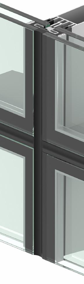
GLASS FRAME DETAIL
1 3-6mm Aluminium Composite Panel
2 Transom Profile
3 Aluminium Fixing Section
4 Pressurised Equalised Foam Glazing Tape Weather Seal
5 16mm Tempered Clear Glass
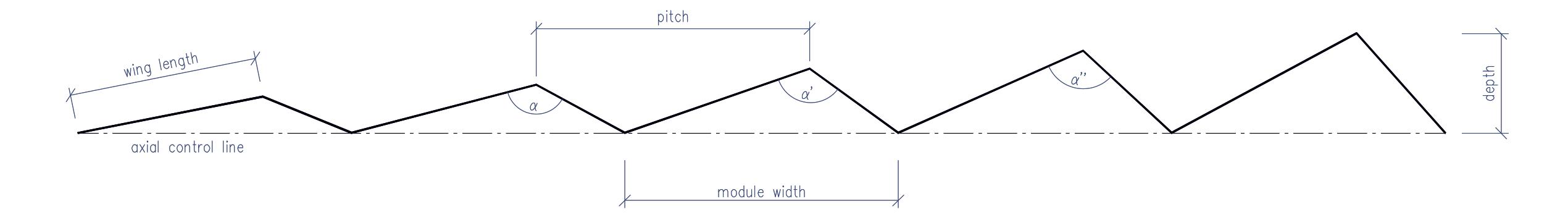
Module width= 150 cm
Pitch= varies
North wings= glass panel
South wings= aluminium panel
Serrated angle= control by 1.5 sinusoidal mapping
Module width= 150 cm
Pitch= varies
East wings= glass panel
West wings= aluminium panel
Serrated angle= control by 1.5 sinusoidal mapping
SOUTH FACADE
Module width= 100 cm
Pitch= varies
West wings= glass panel
East wings= aluminium panel
Serrated angle= control by 1.5 sinusoidal mapping
WEST FACADE
Module width= 150 cm
Pitch= varies
North wings= glass panel
South wings= aluminium panel
Serrated angle= control by 1.5 sinusoidal mapping
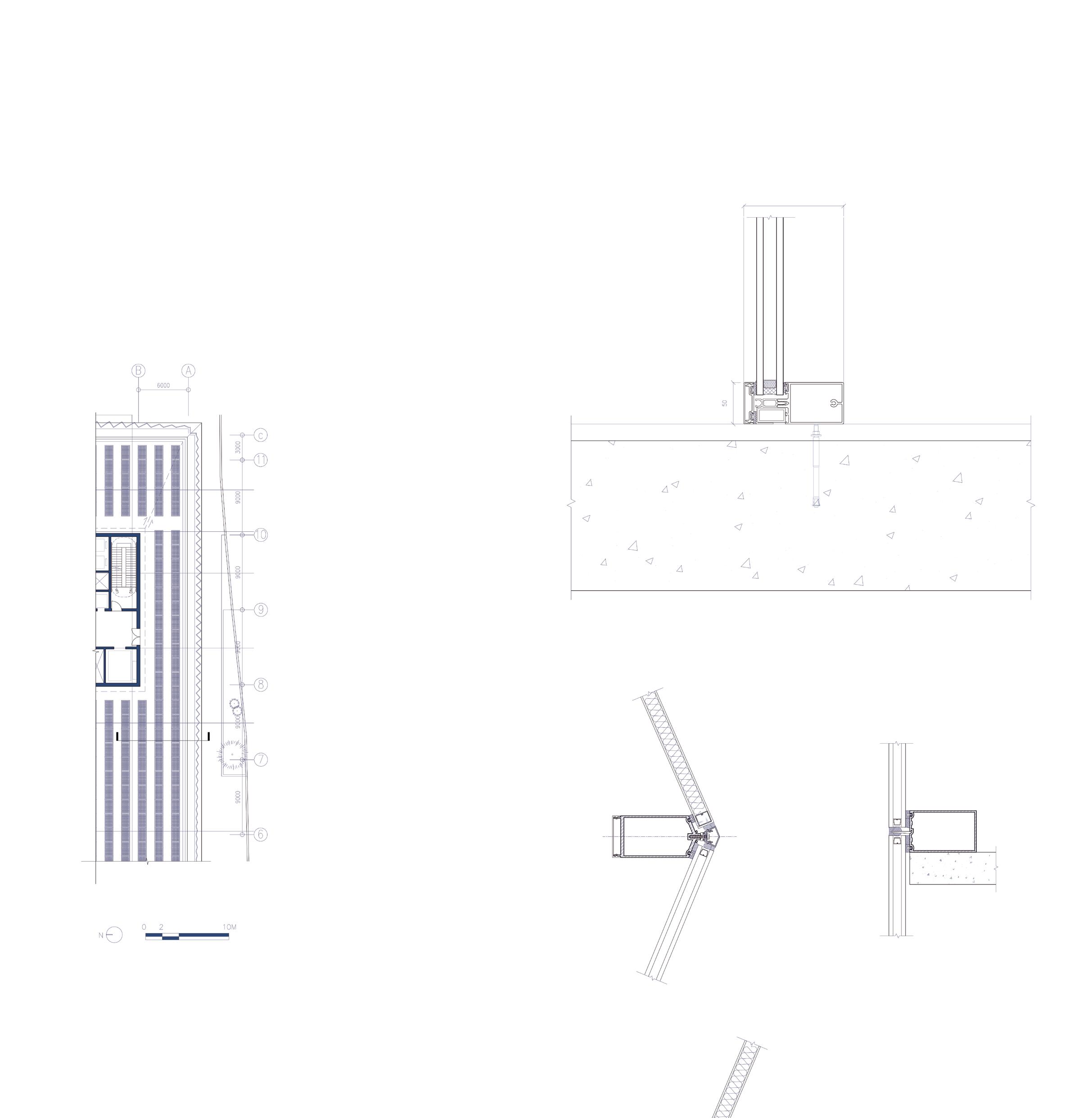
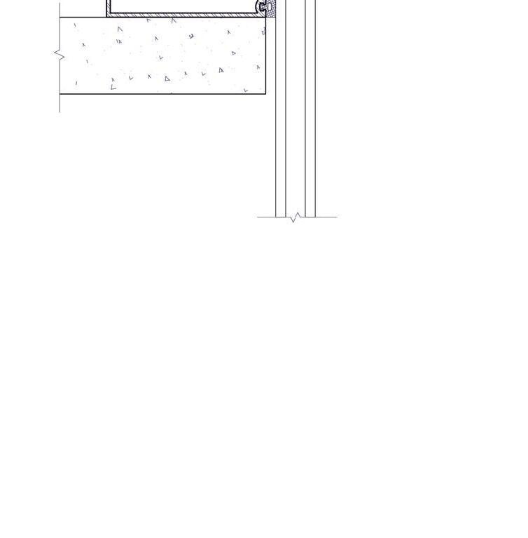
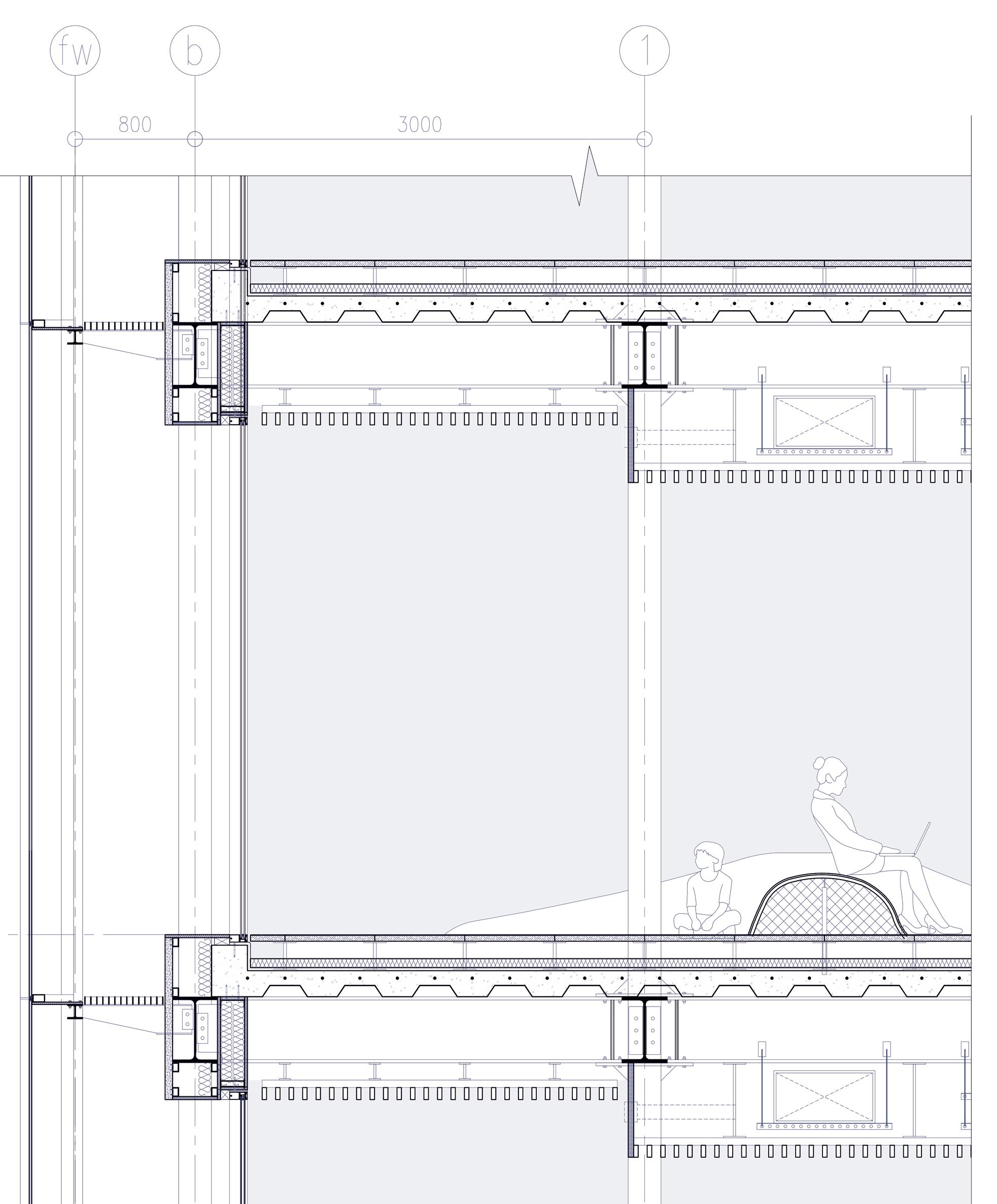
The technical details of the section help us in understanding the system even better.
They depict the different stratifications of the facade support system and its anchor to the hat-truss element which provides it with the lightness and functionality seen from the elevations. Insulation and thermal efficiency is also considering by taking care of the wrapping of the insulatory material chosen to avoid any thermal breaks since Milan can have some harsh winter conditions.
Beyond aesthetics, the interplay of light and shadow has energy-efficient implications. By strategically controlling sunlight, the need for excessive air conditioning and artificial lighting can be minimized, resulting in a more sustainable building.
The inner facades, as the real profile of the building, are composed of insulated claddings and insulating glasses. The serrated outer facades, on the other hand, are composed of aluminium panels and clear glasses.
Between these two façades lies a maintenance corridor. It’s more than just a practical necessity; it’s a space of utility and hidden beauty. This corridor, a calculated distance of 800mm, not only accommodates maintenance needs but also doubles as an ingenious ventilation facade.

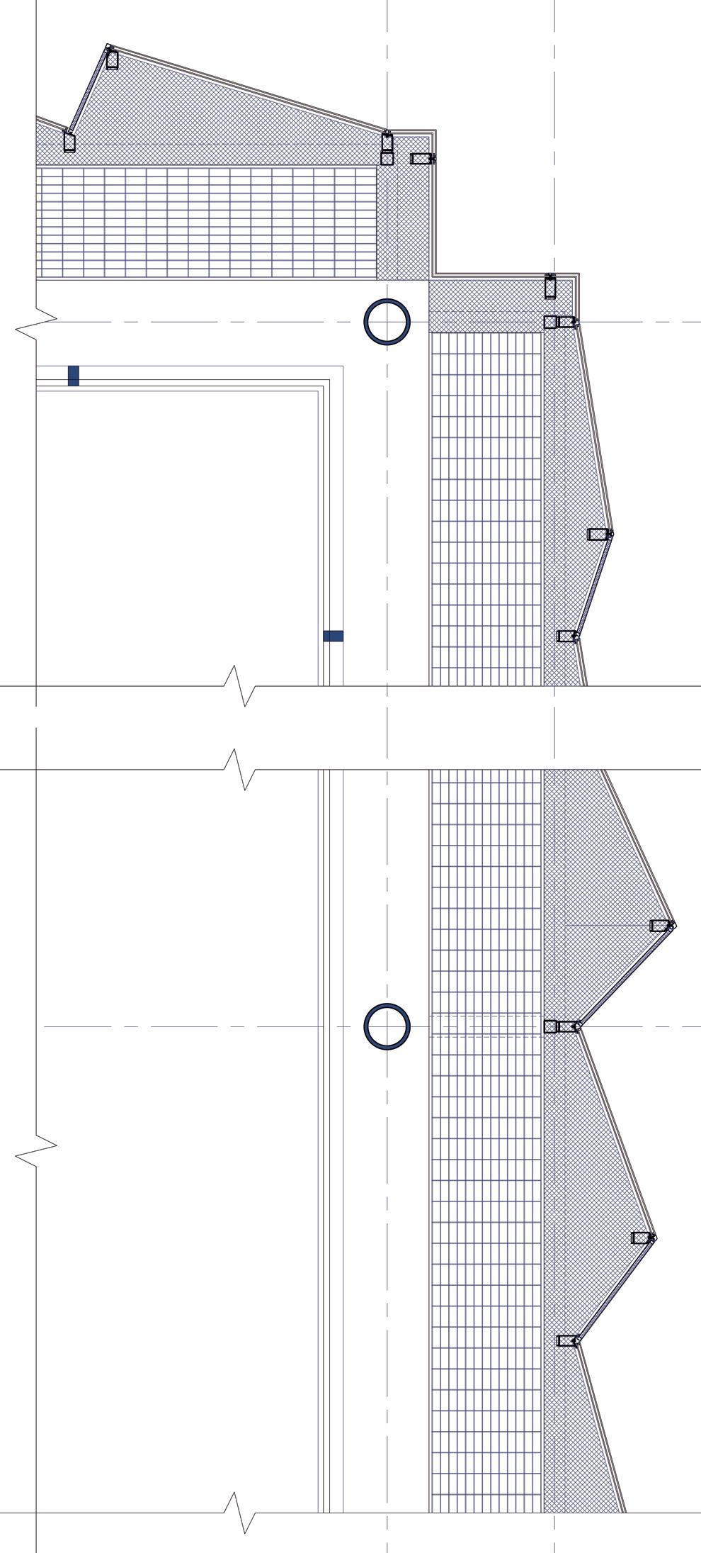

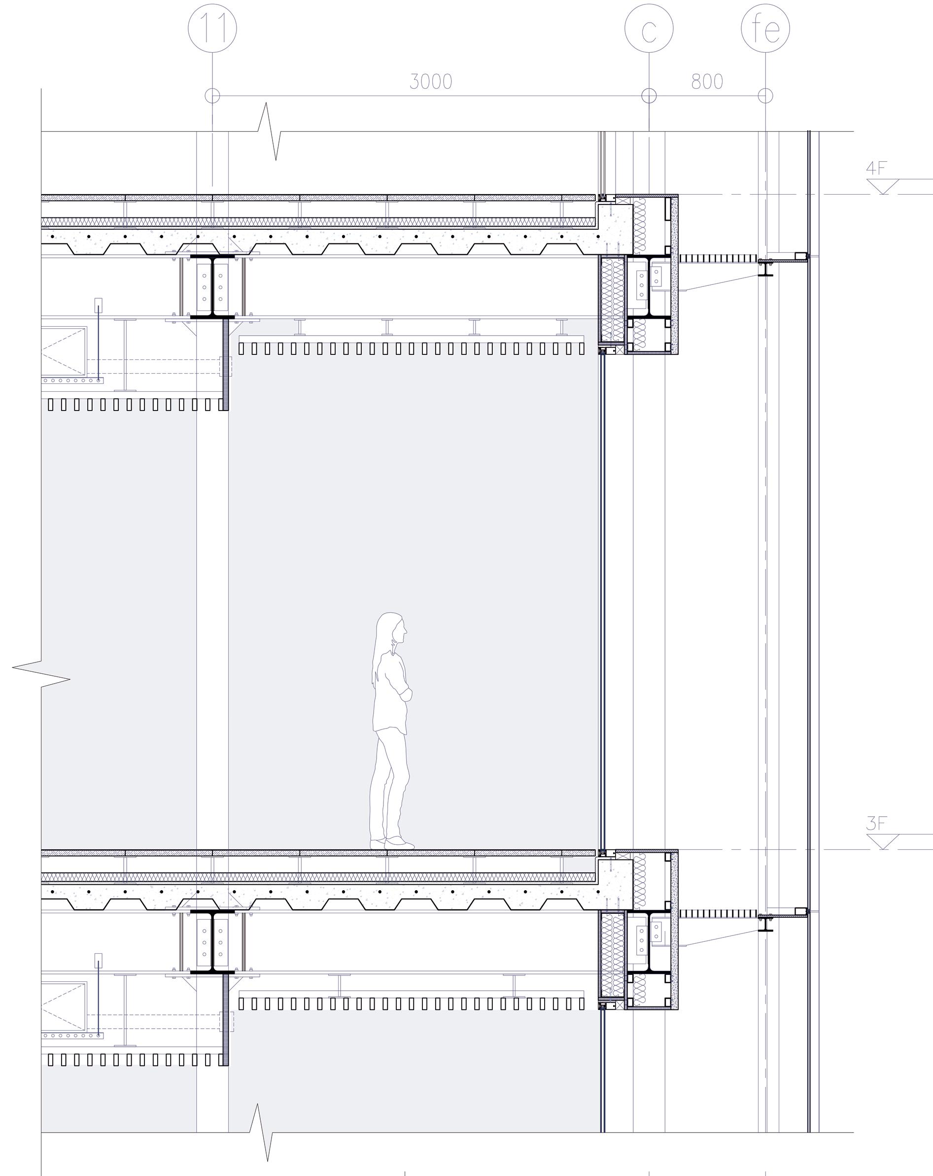
FACADE DETAIL
1 20mm Finishing Tile
2 Inner Facade Cladding
3 HEA 450 Beam
4 Steel Dry Wall Structure
5 220mm Suspended Cable
6 80mm KNAUF Insulation
7 Curtain Glass System
8 Ventilation Air Cavity
9 Maintainance Corridor
10 Secondary Facade Support Structure with HEA 100
11 85mm x 50mm Facade Mullion
12 15mm THK. Aluminium Backing Layer
13 Steel Connecting Plate
14 Alternating Glass and Aluminium Facade
1
2
3
4

INNER FACADE
GLASS FRAME DETAIL
a 16mm Tempered Clear Glass
b 16mm Air
c EPDM Gasket
d Transom Profile
e Expansion Belt Anchor
f Concrete
OUTER FACADE
GLASS FRAME DETAIL
g EPDM Gasket
h Pressurised Equalised Foam
Glazing Tape Weather Seal
i Transom Profile
j Steel Supporting Panel
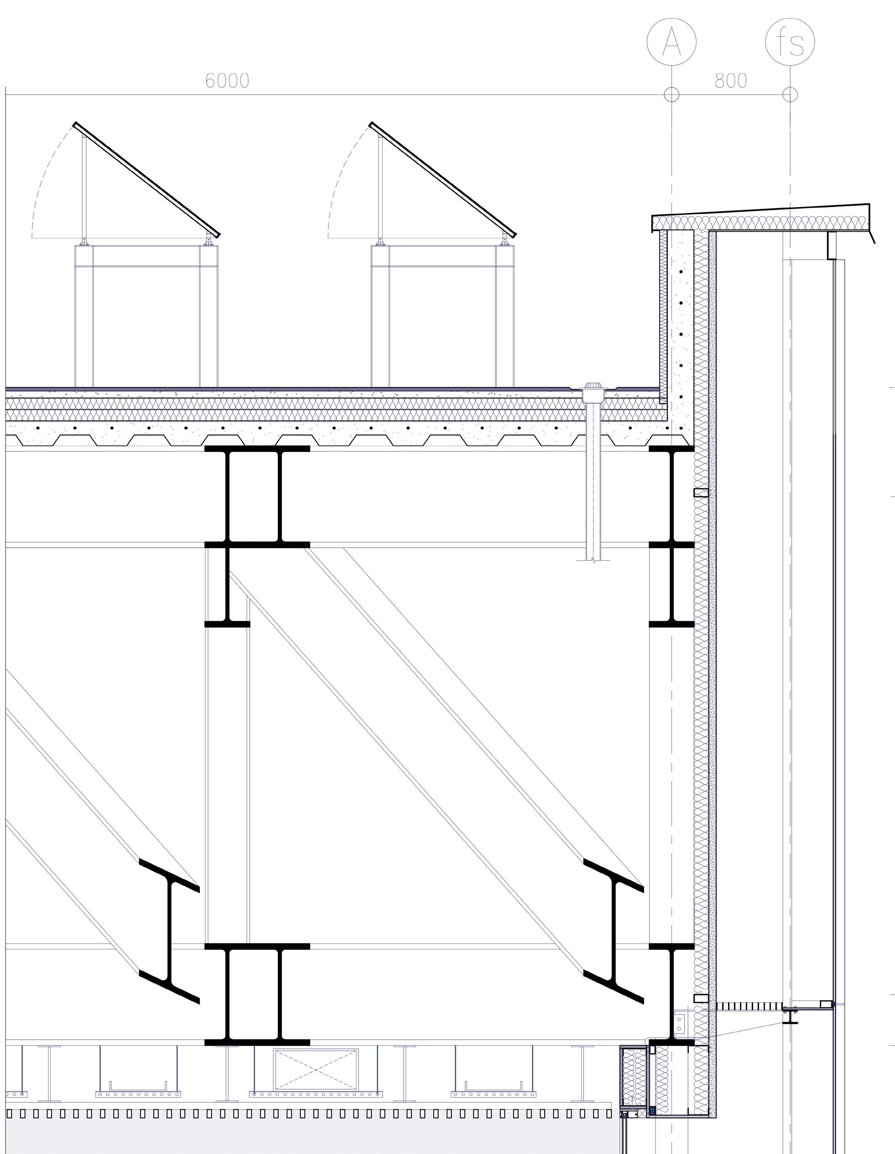
ROOF SECTION DETAIL
1 Galvanised Steel Sheet Roof Capping
2 Galvanised Steel Z-Bar Flashing
3 Head Wall Metal Flashing
4 Cladding
5 Solar Panel & Support (Refer Detail RF page)
6 Facade Secondary Support Structure
7 Roof Concrete Finishing Tiles
8 Rainwater Drainage Duct
9 2mm Steel Metal Deck Sheet with Concrete Fill
10 Truss Structure HEM 700
11 Concrete Screed with Water Proofing
12 100mm KNAUF BODEN Insulation
13 Steel Dry Wall System
14 False Ceiling System
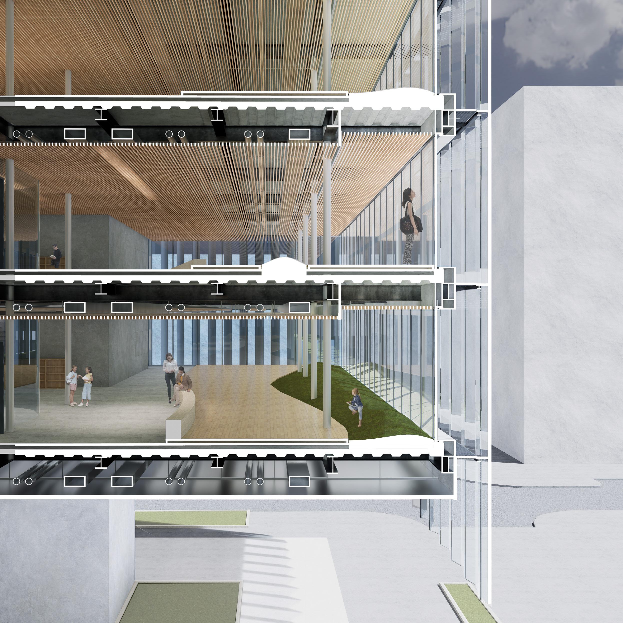
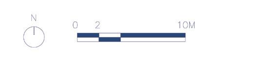
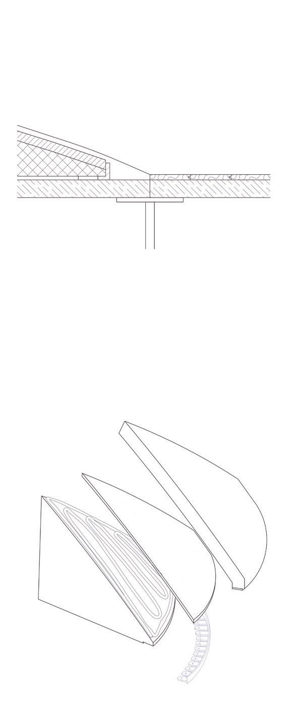
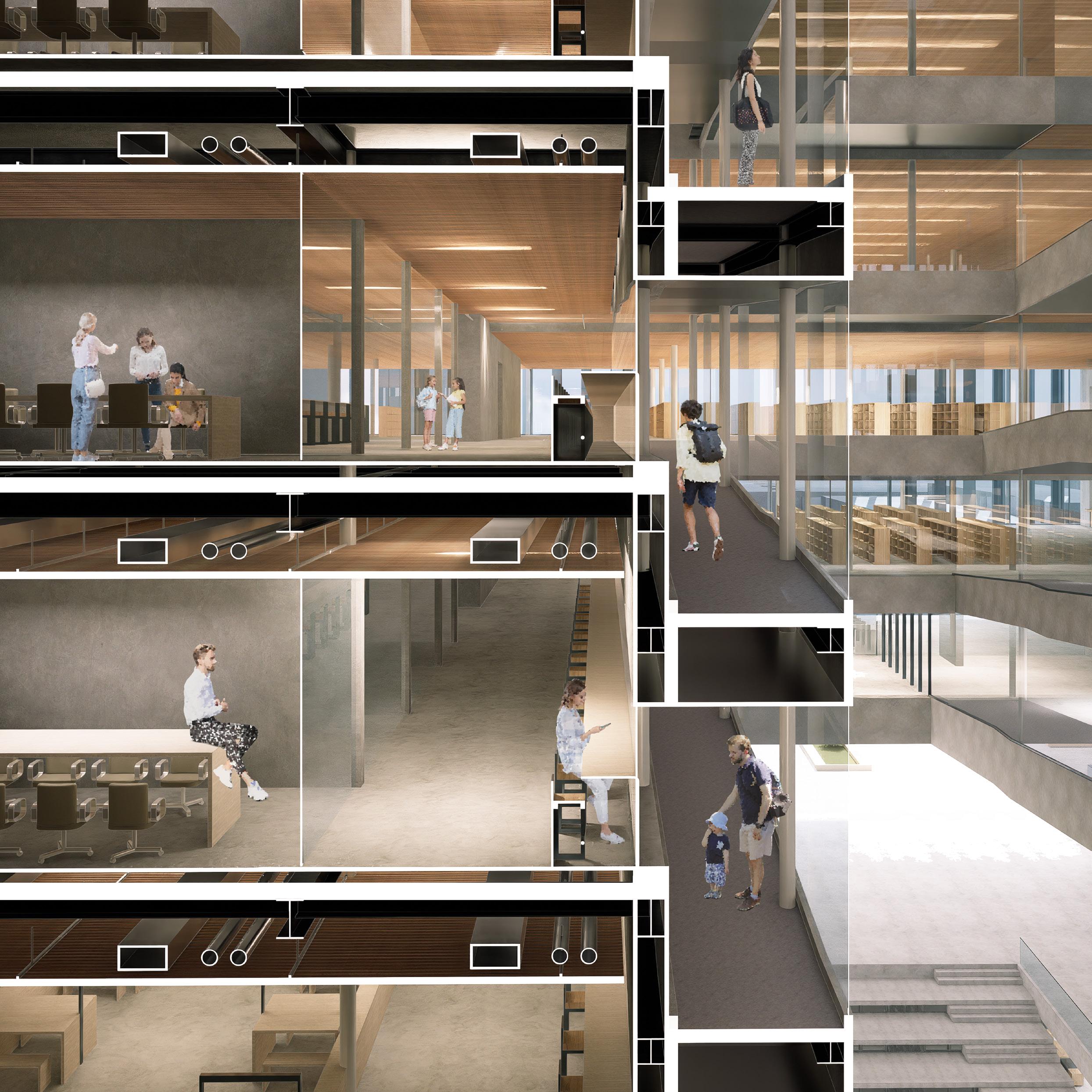
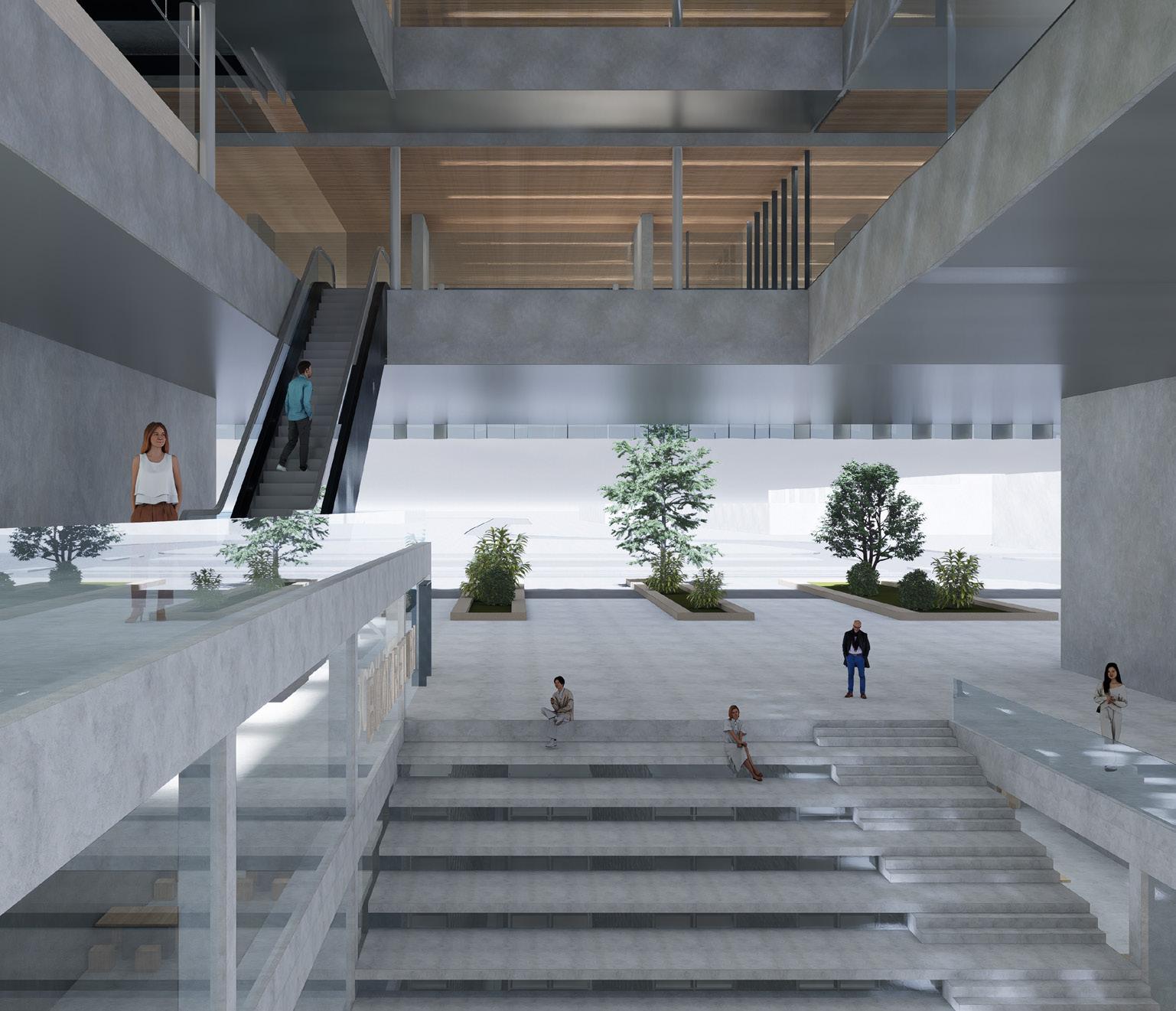
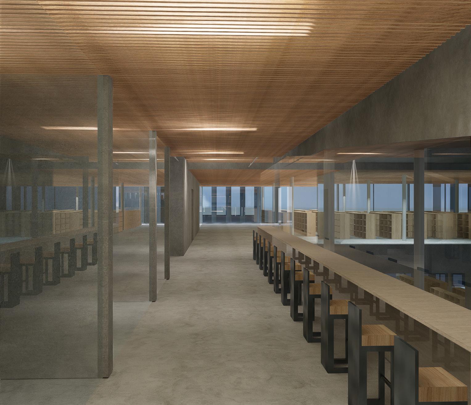
A wooden false ceiling, a canopy that conceals building services ducts or HVAC pipes traverse through the section overhead. They start at a cozy 3 meters high but, as you move deeper towards the periphery of the plan, they rise higher to about 3.4 metres, making the space feel grand and airy. The once-occupied volume at the end now gives way to a dynamic mechanical efficiency and contributes to the speciality of the space which is desrcibed further below.
The split floors of the building’s western section have an “interaction zone” where users meet a designed artificial landscape. This sculpted mound acts as a special zone, visually joining the inner space to the lush exterior park. Beyond being merely a piece of furniture, it represents a leap from traditional reading aids, bringing the mind into a space of active participation and creative thought.
This area was designed as a retreat for knowledge creation and has a calm, contemplative atmosphere. This room’s design is stitched together with a diverse selection of furnishings, each inviting different types of reading.
The atmosphere invites the mind to roam, to integrate, and to create inside a space intended to promote both meditative solitude and group innovation through an assortment of furnishings, textures, and quiet rooms.
At the top layer, you’ll find artificial grass, it’s a tactile invitation to connect with nature even indoors. You can sit, lie down, or just feel the green beneath your fingers. Just beneath the grass, there’s a hidden layer of protective foam. It’s a soft shield that keeps you comfortable. At the heart of this landscape, there’s a foam core. This is what gives the mound its shape. It’s designed to be lightweight and sturdy, making it perfect for an indoor space.
On the ground floor, the false ceiling is of reflective steel sheets that create a visual illusion that the space is much larger and spacious than it actually is. They also establish a connection with the public realm. They reflect the surrounding environment, It’s an invitation for passersby to engage with the space, blurring the boundary between inside and outside.
1
2
3 Section
a 10-25 mm Artificial Grass
b 22mm Protective Foam Layer
c Duratherm EPS (125) Foam Core
d HDPE Nailer for Securing
e Raised Floor Support
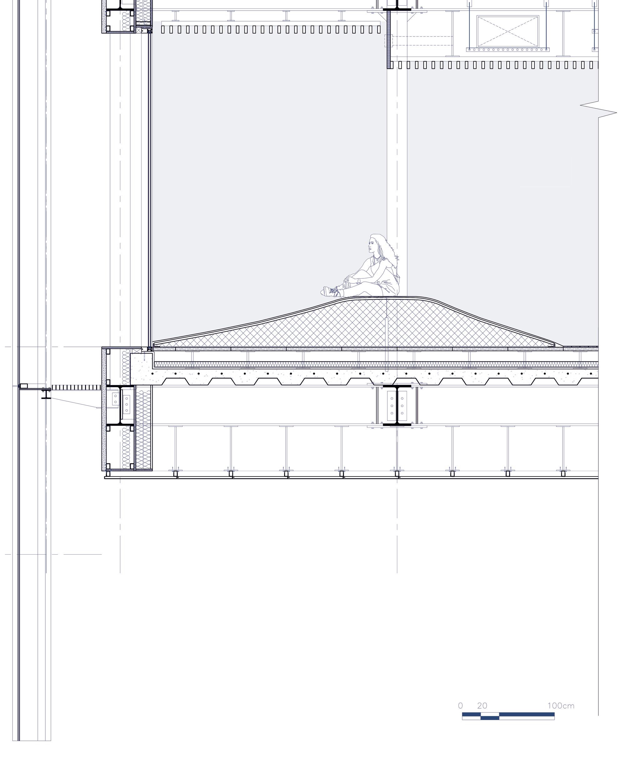
1 Detail of Interior landscape (layers)
2 Section Detail ‘Sec E’ forcus on interior landscape & false ceiling
INTERIOR LANDSCAPE DETAIL (LAYERS)
f Artificial Grass
g JSP (EPP) Protective Foam Layer
h Expandable Urethane Glue
i Duratherm (EPS) Foam Core
j HDPE Nailer for Securing
The inclined ramp connecting the library floors is a key architectural element. It runs alongside the central void and is encased in glass, providing a visual and safe experience for users. The structural support and connection for this ramp is designed to ensure stability and safety.
To enhance safety and assist users as they climb the ramp, a handrail is installed. The handrail is positioned at a height of 2 meters, offering a secure grip for individuals moving up or down the ramp.
The surface of the ramp is designed with a suitable flooring material that provides tractionl. As in the section of a standard floor, beneath the ramp’s surface, there is a designated space for mechanical ducts for housing essential utilities. It is followed by a suspended ceiling which is a aesthetic and finishing element to hide the service ducts.
In the section where the ramp connects to the normal floor, there’s a continuation of a drywall steel wall. This wall extends until it meets an HEA beam, which plays a crucial role as one of the support links within the structure.
Another obvious support systems are the suspended columns with a diameter of Ø219.1mm. These columns serve as strong vertical supports, securing both ends of the ramp firmly in place. They contribute to the structural integrity and stability of the entire system.
The materials chosen for cladding and flooring of the ramp are exposed concrete and stone tiles whoch follow the palette of the sunken plaza but it is complemented with modernity and transparency by the glass enclousres where it overlooks into the main central void.
The ramp attempts to tell a story and follow a path to experience the different facets of our library floors. It is hence kept very light and purposive to fortify the spatial quality.
RAMP DETAIL
NORTHEN RAMP TOWARDS
CENTRAL VOID
1 Suspended Column Support; Ø219.1mm
2 Glass Enclosure towards Void
3 Reading Furniture
4 Finishing; Stone Tile
5 Handrail Support at 2m
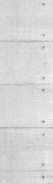
6 Cladding Finish; Exposed Concrete
7 Fire Stop
8 Aluminium Finishing
9 Curtain Back Support
10 Mechanical Duct Space
11 Suspended Ceiling
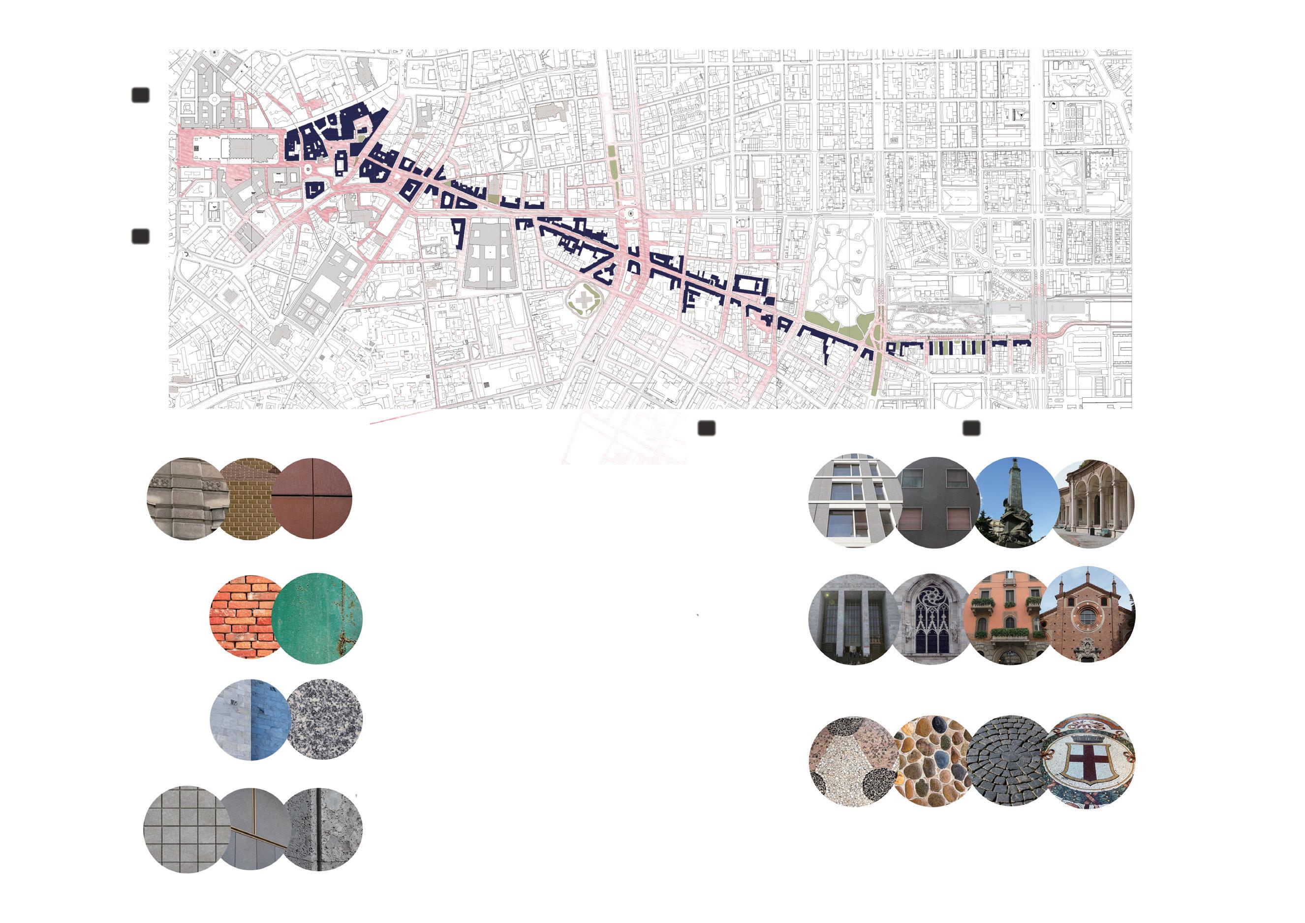
In the materiality aspect of our design, we have rendered distinct personas to the two different architectural volumes.
We started from observing the surroundings. Through the walk in the city we took notes about the materials, patterns and texture.
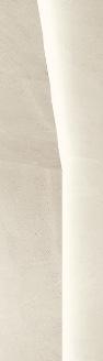
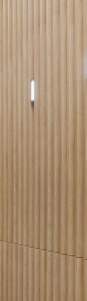
The flooring and wall coverings of the Upper Library Volume are designed to evoke modernity and lightness. Here, a symphony of materials begins to take shape, achieving compatibility regarding the representation of inner spaces. Some commonly used materials are aluminum and different types/grades of glass.
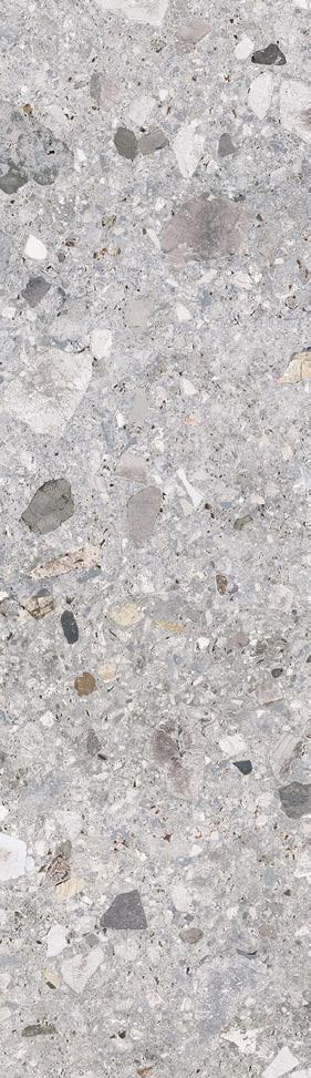
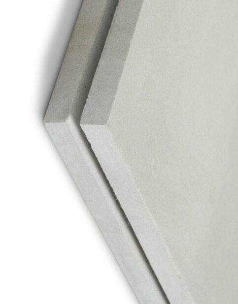
In contrast, the Bottom Sunken Plaza’s canvas is represented as authentically natural. Here, cladding and flooring materials pay homage to the earth’s textures, dependent on the stoneware’s texture and weightiness. This region below and above the ground, interacts tactilely with the underworld and evokes a sensation of rooted presence.
This shows a duet of materiality orchestrating an architectural conversation between the modern and the traditional.


The library’s facade might seem intricate, but the chosen materials keep things straightforward and lightweight. We use;
Aluminium Composite Panels: These panels, sourced from Gesamtverband in Germany, come in 3mm, 4mm, and 6mm thicknesses. They’re like sturdy layers that form the outer surface of the facade.
Curtain Glass System (R70ST by RiVENTi, Spain): This glass system, with a thickness of 50mm, acts like a transparent curtain, allowing light to enter while maintaining insulation. It’s energy-efficient, with a rating of 1.2 W/sqmK.
Double/Triple Insulation Glass (Okalux, Sweden): Okalux, from Sweden, provides the double or triple insulation glass. It’s 40mm thick and helps regulate temperature and light.
The materials used are quite straightforward. These include composite panels, energy-efficient glass systems, insulation glass and cast glass. Together, they create a facade that’s both functional and visually appealing.


Materials:
Producer:
Location:
EPD no.:
Thickness:
Aluminium Composite Panels Gesamtverband Germany
EPD-GDA-2019132-IBG1-EN 3 mm/ 4 mm/ 6 mm
Materials:
Product name:
Producer:
Location:
EPD no.:
Thickness:
Transmittance:
(Thermal)
Materials:
Product name:
Producer:
Location:
EPD no.:
Thickness:
Curtain Glass System R70ST
RiVENTi Spain
S-P-01078
50 mm
1.2 W/sqmK
Materials:
Product name:
Producer:
Location:
Dimensions:
EPD no.:
Double/ Triple Insulation Glass
Okalux
Okalux Glastechnik Sweden
M-EPD-MIG-GB-002029
40 mm
Cast Glass
LINIT U-Profiled Chord finish Glasfabrik Lamberts Germany
250 x 60 x 60 mm
EPD-LPG-GB-28.1
The materials used here, like the cladding and flooring, pay tribute to the natural textures. They echo the feel of real stone, making you feel connected to the ground.
To create this feeling, we used materials like ready-mix concrete, porcelain stoneware, laminated porcelain stoneware, and a suspended ceiling with a mineral binder.
In this project, Lafarge’s ready mix concrete, sourced from Greece, is a foundational material. It’s a versatile concrete mixture known for its consistency and quality.
The interior design of the space incorporates Italgraniti’s porcelain stoneware, imported from Italy. These thin yet robust tiles offer a striking resemblance to the natural Ceppo di Gre stone. With dimensions of 160 x 320 millimeters and a thickness of 0.6 mm, they are both elegant and durable.
Cotto d’Este, an Italian manufacturer, supplies the laminated porcelain stoneware for this project. These tiles, like the previous ones, mimic the appearance of natural stone.
In simpler terms, while the steel exterior plays with lightness, the Sunken Plaza is all about authenticity.

Materials:
Producer:
Location:
EPD no.:
Materials:
Product name:
Producer:
Location:
Dimensions:
Materials:
Product name:
Producer:
Location:
EPD no.:


Materials:
Product name:
Producer:
Location:
Dimensions:
Reflectance:
Ready Mix Concrete
Lafarge
Greek
S-P-04988
Porcelain Stoneware
Ceppo di Gre
Italgraniti
Italy
160 x 320 x 0.6 mm
Laminated Porcelain Stoneware
Lime Stone-honed
Cotto d’Este
Italy
EPD-004-PGR-ver.1
Suspended Ceiling with Mineral Binder
ADAGIO Acoustic+
Knauf Ceiling Solutions
France
600 x 600 mm
90%
As we enter the interiors, the materials embrace the idea of luminosity and reflection, revealing areas that are left uncovered to emphasize architectural transparency. The warmth and lightness of the materials chosen are to serve as a deliberate canvas for the development of information and original ideas inside the library’s space. It is intended to create a hospitable and comfortable interior with an interplay of design intent and daylight.
The material we’re using is stainless steel. It comes in two varieties: water ripple and stamped sheets. These sheets are crafted by Steel Color S.p.A. in Italy, thicknesses ranging from 0.3mm to 3mm. These stainless steel sheets are both durable and visually intriguing.
Sound Insulation has also been carefully considered to provide the user’s with an optimum environment.
Materials:
Product name:
Producer:
Location:
EPD no.:
Fibre Cement/Concrete
Aquapanel Cement Board
Knauf Ceiling Solutions Germany
EPD-USG-20210120-IBA1-EN
Materials:
Product name:
Producer:
Location:
EPD no.:
Wood, Laminate Based Panel
Wood False Ceiling
Sepia
Aspen
Berlin, Germany
EPD-ASP-20160121-CAC1-EN
Materials:
Product name:
Producer:
Location:
EPD no.:
Thickness:


Materials:
Product name:
Producer:
Location:
EPD no.:
Stainless Steel Water Ripple Sheet
Stainless Steel Stamped Sheet
Steel Color S.p.A. Italy
S-P-00690
0.3mm-3mm
Clay Stoneware Tiles
Porcelain Ceramic Tiles
Gruppo Ceramiche GRESMALT Italy
EPDITALY0080
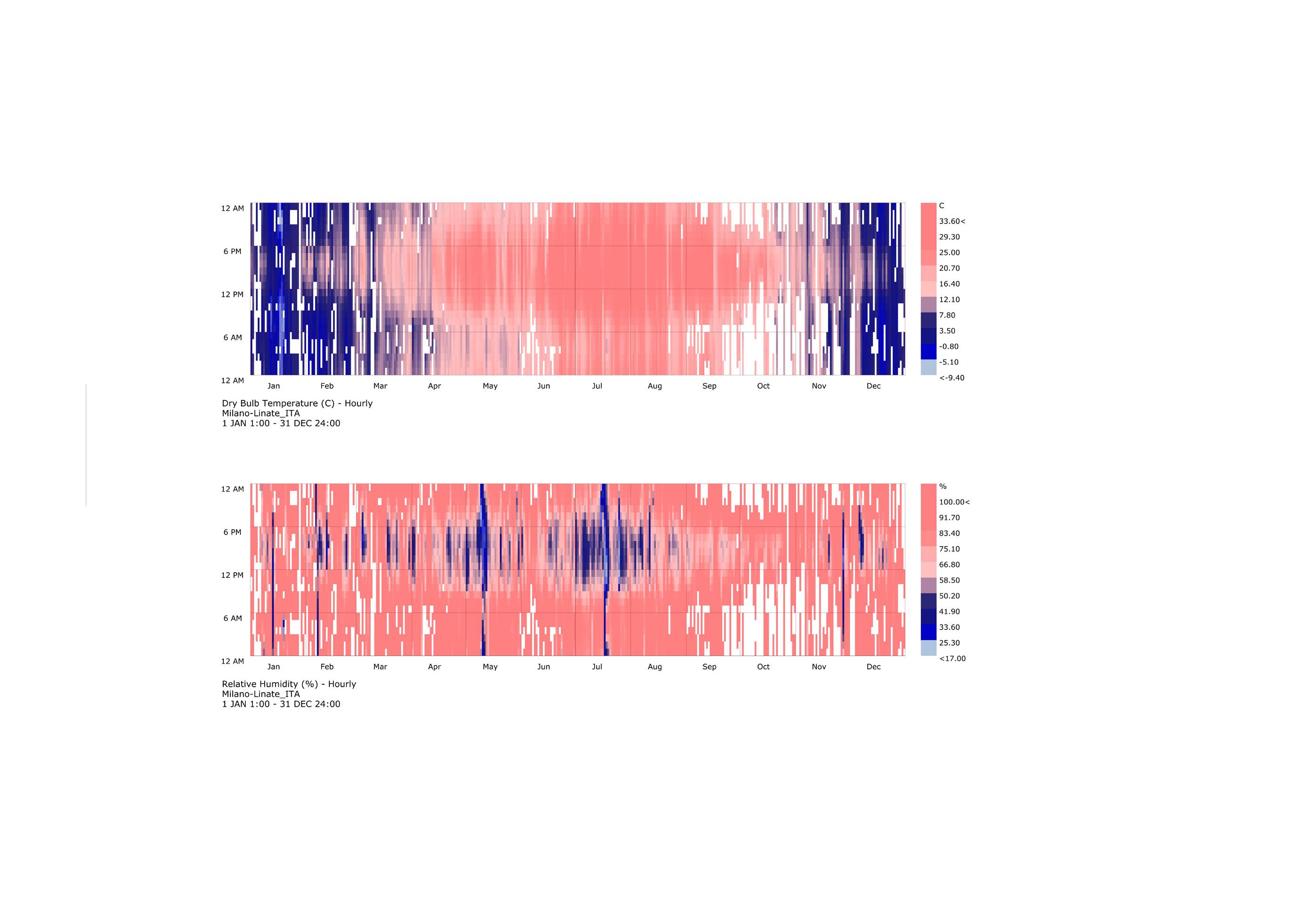
Heating Degree Days (HDD) and Cooling Degree Days (CDD) are measures used to quantify the demand for heating and cooling, relative to a reference temperature. These metrics provide insight into the energy requirements for temperature control in buildings.
For Milan, where the climate is Mediterranean with distinct seasons, the HDD and CDD values can be significant and is important to know so as to implement right measures in the design.
HDD indicates the severity and duration of cold weather while CDD reflects the demand for air conditioning.
Below is the data we calculated:
HDD: Milan experiences a considerable number of heating degree-days due to its cold winters. The HDD values can be an average of 2100s, for the years 20152020.
CDD: Summers in Milan can be warm, leading to a notable demand for cooling. The CDD values can vary from around 70s, reflecting the need for air conditioning during the hottest months.
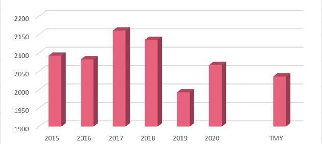
Heating Degree Days of 2015-2020, Compare with TMY
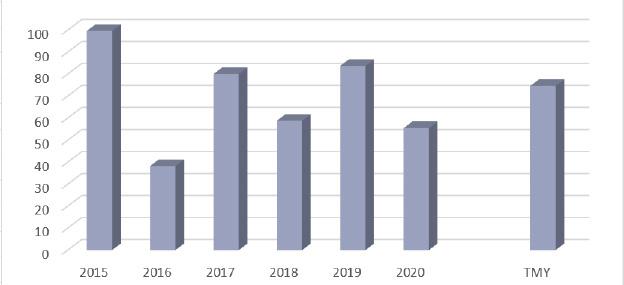
Cooling Degree Days of 2015-2020, Compare with TMY
Thermal transmittance value (U-value) is important to measure a building element is effectiveness as an insulator, indicating how much heat can pass through it. We have analyzed the typical sections of our building, considering the thermal properties of the materials, the cross sections and the overall heat transfer through these components.
The calculated values were positive and in the optimum range of <0.24.
Temperature and dew-point temperature in the component. The dew-point indicates the temperature, at which water vapour condensates. As long as the temperature of the component is everywhere above the dew-point temperature, no condensation occurs. If the curves have contact, condensation occurs at the corresponding position.
Roof Updated
Thermal protection
U = 0,23 W/(m²K)
GEG 2020 Bestand*: U<0,24 W/(m²K)
excellent insufficient
Moisture proofing
No condensate excellent insufficient
All statements without guarantee
Roof construction created on 30.6.2023
Heat protection
Temperature amplitude damping: 93 phase shift: 12,0 h
Thermal capacity inside: 221 kJ/m²K
excellent insufficient
1 trapezoidal sheet (75 mm)
2 Reinforced concrete (100 mm)
3 Knauf Insulation Boden-Dämmplatte TPD (80 mm)
4 Knauf Insulation Boden-Dämmplatte TPD (80 mm)
Roof Updated, U=0,23 W/(m²K)
Temperature profile
Temperature profile
5 BITUMAT PVC Waterproofing Membrane
6 Cement screed (50 mm)
7 Knauf AQUAPANEL Cement Board Floor (22 mm)
All statements without guarantee
Impact of each layer and comparison to reference values
For the following figure, the thermal resistances of the individual layers were converted in millimeters insulation. The scale refers to an insulation of thermal conductivity 0,040 W/mK.
1 trapezoidal sheet (75 mm)
2 Reinforced concrete (100 mm)
3 Knauf Insulation Boden-Dämmplatte TPD (80 mm)
Knauf Insulation Boden-Dämmplatte TPD Knauf Insulation Boden-Dämmplatte TPD Equivalent insulation thickness (WLS 040)
4 Knauf Insulation Boden-Dämmplatte TPD (80 mm)
5 BITUMAT PVC Waterproofing Membrane
6 Cement screed (50 mm)
7 Knauf AQUAPANEL Cement Board Floor (22 mm)
Temperature and dew-point temperature in the component. The dew-point indicates the temperature, at which water vapour condensates. As long as the temperature of the component is everywhere above the dew-point temperature, no condensation occurs. If the curves have contact, condensation occurs at the corresponding position.
Layers (from inside to outside)
(Anlage 7, Zeile 5a,5b).
PDFor Profi-Option (from 2.99 € / month plus VAT).
Commercial use only with
€ / month plus VAT).
Commercial use only with Plus-, PDFor Profi-Option (from 2.99