
Commitment to Sustainability and Performance in the Built Environment


Pushing the Envelope Canada
A publication of the Building Science Association of Ontario Spring 2025
Published For:
The Building Science Association of Ontario
2800 – 14th Ave.
Suite 210
Markham, ON L3R 0E4
Phone: 647-317-5754
Fax: 416-491-1670
info@bsao.ca www.bsao.ca
©2025 Matrix Group Publishing Inc. All rights reserved. Contents may not be reproduced by any means, in whole or in part, without the prior written permission of the publisher. The opinions expressed in this publication are not necessarily those of Matrix Group Publishing Inc. Printed in Canada.
BSAO does not specifically endorse the editorial, products or services contained within this magazine. These products and services are presented here as an indication of the various possibilities in the Marketplace. BSAO wishes to advise the reader that sound Building Science Practices should be applied to any and all product or service selections. BSAO does not make or imply any warranties as to the suitability of any of these products or services for any specific situation. Furthermore, the opinions expressed in this magazine’s editorial content may not necessarily reflect the opinions of BSAO.


Pushing the Envelope Canada
A publication of the Building Science Association of Ontario Spring 2025
Published By:
Matrix Group Publishing Inc.
Return all undeliverable addresses to:
309 Youville Street
Winnipeg, MB R2H 2S9
Toll Free: 1-866-999-1299
Toll Free Fax: 1-866-244-2544 www.matrixgroupinc.net
Publications Agreement Number: 40609661
President & CEO
Jack Andress
Operations Manager
Shoshana Weinberg sweinberg@matrixgroupinc.net
Senior Publisher
Jessica Potter jpotter@matrixgroupinc.net
Editor-in-Chief
Shannon Savory ssavory@matrixgroupinc.net
Editor / Social Media Manager
Jenna Collignon
Finance /Administration
Lloyd Weinberg, Nathan Redekop accounting@matrixgroupinc.net
Director of Circulation & Distribution
Lloyd Weinberg distribution@matrixgroupinc.net
Sales Manager
Jeff Cash jcash@matrixgroupinc.net
Sales Team Leader
Colleen Bell
Matrix Group Publishing Inc. Account Executives
Colleen Bell, Jackie Casburn, Chandler Cousins, Rich Cowan, Rob Gibson, Jim Hamilton, Frank Kenyeres, Sandra Kirby, Andrew Lee, Brian MacIntyre, Chad Morris, Lynn Murphy, Wilma Gray-Rose, Monique Simons, Joseph Ukaoha
Layout & Design
Travis Bevan
Advertising Design
James Robinson
©2025 Matrix Group Publishing Inc. All rights reserved. Contents may not be reproduced by any means, in whole or in part, without the prior written permission of the publisher. The opinions expressed in this publication are not necessarily those of Matrix Group Publishing Inc. Printed in Canada.
BSAO does not specifically endorse the editorial, products or services contained within this magazine. These products and services are presented here as an indication of the various possibilities in the Marketplace. BSAO wishes to advise the reader that sound Building Science Practices should be applied to any and all product or service selections. BSAO does not make or imply any warranties as to the suitability of any of these products or services for any specific situation. Furthermore, the opinions expressed in this magazine’s editorial content may not necessarily reflect the opinions of BSAO.
MEET OUR EXPERTS
CHRISTINE ASFOUR-META
Christine Asfour-Meta is a Building Envelope Consultant at Durabond Products Limited, with over sixteen years of experience in EIFS cladding.
HELEN STOPPS, PH.D.
Helen Stopps, Ph.D., P.Eng., is an Assistant Professor in Architectural Science at Toronto Metropolitan University (TMU) and co-lead of the From Harvest to House program.
SARAH HAINES, PH.D.
Sarah Haines, Ph.D., is an Assistant Professor in the Department of Civil & Environmental Engineering at University of Toronto and co-lead of the community-based research program, From Harvest to House.
MARIA MILAN, PH.D.
Maria Milan is a Ph.D. student in Building Science at Toronto Metropolitan University.
ODEL LINETSKA
Odel Linetska is a M.A.Sc student in Building Science at Toronto Metropolitan University.
NATALIE CLYKE
Natalie Clyke is both Project Manager of From Harvest to House, and Founder and CEO of RockTree Mgo Construction Materials Inc.
BECKY BIG CANOE
Becky Big Canoe is the co-founder of the Mno Aki Land Trust, a member of the Keepers of the Circle and the founder of EnviroNative Training Initiatives.
OSKAR LINKRUUS
Oskar Linkruus is a third-year student in Algonquin’s Bachelor of Science, Building Science Honours program.
NICHOLAS ASISTORES
Nicholas Asistores is a third-year student in Algonquin College’s Building Science Honours program.

TAOFIQ AL-FAESLY, PH.D.
Dr. Taofiq Al-Faesly is a distinguished educator and engineer with over 30 years of experience in academia and industry.

EMILY SALEH
Emily Saleh is a Senior Associate with 30 Forensic Engineering’s Civil & Structural Engineering Group, specializing in Building Science.
AUSTIN TODD

Austin is the Founder and President of Evergreen Building Science Inc. and a building science and sustainability professional.
JAVERIYA HASAN, PH.D.


Javeriya Hasan is an Associate at 30 Forensic Engineering, specializing in Civil & Structural Engineering and Building Science.
TERRENCE HOLDER
Terrence Holder is the Technical Director of the Civil & Structural Engineering and Building Science & Building Envelope groups at 30 Forensic Engineering.
JULIE SZABO
Julie Szabo is an Associate Principal at Wiss, Janney, Elstner Associates, Inc., with over 20 years of experience in building science and building enclosure consulting.

JASON SANCHEZ


Jason Sanchez is a Senior Associate at Wiss, Janney, Elstner Associates, Inc., with 18 years of experience in building enclosure consulting where his work focuses on project management and technical advisement.
CHUCK BUNDRICK
Chuck Bundrick, CSI, LEED GA, is a Key Account Executive – Commercial Construction and Renovation at Tremco Construction Products Group.


Daniel Aleksov Principal & Co-Founder Leading Edge Building Engineers
As we wrap up a more formidable winter and approach spring, it is important to reflect on the last six months of some major initiatives the Ontario Building Envelope Council (OBEC) has implemented and is actively engaged in. Our joint OBEC/IIBEC BES Conference held last fall was by all accounts a major success thanks to the participants of both associations as well as the countless efforts of our board and committee members, authors, speakers, sponsors and members at large. We appreciate the support and commitment that helped make this major undertaking a memorable and beneficial experience.
During our annual general meeting held on October 1, 2024, we made the announcement that the association was officially changing its name to the Building Science Association of Ontario (BSAO) in accordance with the special members vote which passed. The rebranding and new website www.bsao.ca was launched on January 17, 2025. Additionally, it was announced at the AGM that
Message from the President
Paul Pushman from EXP was the recipient of the Anthony A. Woods (The Beckie) award, and it was formally presented to him at our recent dinner meeting held on January 15th.
One of the major new initiatives BSAO has formally commenced at the start of this year is hiring a lobby firm to advocate BSAO’s strategic goals to government officials and agencies further broadening our reach and impact across the province of Ontario. Any important updates will be communicated to our members regularly through emails, social media, events, and publications.
We have an outstanding lineup of events planned for this year which include our regular dinner seminars, webinars, a lab tour, our second annual golf tournament with the Canadian Condominium Institute (CCI) Golden Horseshoe chapter and our fall full day conference and AGM. We look forward to our membership to participate, benefit, and sponsor these high calibre events as they become open for registration.
We are thrilled that post-secondary students continue to become BSAO members and host their own student chapter events as well as attend BSAO organised events. Many thanks to our corporate sponsors who have facilitated and supported this initiative for the past few years. This year the rising star award will be granted to an individual, nominated by their peers, to recognize individuals that demonstrate exceptional knowledge of the design, construction and performance of the building envelope.
In closing, we have made some incredible strides to further BSAO’s mission to be the beacon of excellence for building science and we appreciate all the efforts and support from our members for the major initiatives that we are collectively working on. Additionally, I would like to thank Andrea Mucciarone and Robert Quattrociocchi for their service on the board and their impact. I look forward to working closely with each of you as we navigate on this exciting journey together. If you are interested in volunteering on one of our many active committees, please email us at info@bsao.ca.
President: Daniel Aleksov, P.Eng., BSS, Leading Edge Building Engineers Inc.
Vice-President: Negar Pakzadian, B.Eng., M.Arch., MBSC., BSS, CPHD, Major Capital Project Manager
Treasurer: Matthew Gelowitz, M.A.Sc., CPHC, LEED® AP, Synergy Partners Consulting Ltd.
Operations Manager: Sherry Denesha, Building Science of Ontario
Directors:
Mohammed Dawoud, P.Eng, M.Eng, BSS, CPHD, NFRC Certified Simulator, Ennova Facades
Brandon Gemme, P.Eng., BSS, CPHD, Leading Edge Building Engineers Inc.
Alessandra Valerio, B.Arch., PMP, BECxP, CxA + BE, Stantec
Antoine Possik, Northern Caulking Inc.
Stephanie Martin, M.Sc., P.Eng., MTE Consultants Inc.
Shohreh Salimpour, M.Eng., P.Eng., M.Arch., OAA (Int.), LEED® AP, PMP, OHE Consultants
Kelsey Saunders, KPMB

Ontario Building Envelope Council Rebrands as Building Science Association of Ontario!
The Ontario Building Envelope Council (OBEC) is excited to announce its rebranding as the Building Science Association of Ontario (BSAO). This change reflects our ongoing commitment to advancing the field of building science and our dedication to meeting the volving needs of our industry.
The decision to rebrand comes as part of our strategic initiative to better represent our mission and broaden our outreach to professionals involved in building science. The new name emphasizes our focus on education, research, and collaboration among architects, engineers, contractors, manufacturers, and researchers.
“Our rebranding to the Building Science Association of Ontario signifies our dedication to advocating for building science and provide quality education and forums for collaboration for members to network and increase their technical knowledge,” said Daniel Aleksov, President of BSAO. “We believe the new name captures the essence of our mission and our commitment to sustainability and performance in the built environment.”
BSAO will continue to provide valuable resources, educational programs, and networking opportunities to its members while championing the importance of building science in addressing today’s challenges in construction and sustainability. We invite all stakeholders in the building industry to join us on this exciting journey as we work together to enhance building performance and ensure a sustainable future for Ontario.
We will be updating all OBEC branding to align with the new BSAO branding, including across this issue of Pushing the Envelope Canada. You’ll notice this change occurring in phases. Our new website, www.bsao.ca, will be launched soon. In the meantime, once it goes live, you will be automatically redirected from the current www.obec.on.ca site to the new site.
We are excited about this new direction and look forward to the future of BSAO. If you have any questions, don’t hesitate to contact the BSAO, Operations Manager, Sherry Denesha, at info@bsao.ca.
UPCOMING BUILDING SCIENCE SPECIALIST EXAMS
The Building Science Specialist (BSS) designation recognizes those who meet the strict educational and practical requirements set forth by the BSS Board of Canada (BSSB). This designation has become the benchmark qualification of Building Science practitioners and provides members of the industry, including building designers, specifiers, developers, contractors, and owners, the confidence that any designation holder has a high level of education and understanding in the field of Building Science as deemed by the BSS Advisory Committee, composed of key industry figures.
Register today here: https://bssb.ca/bss-exam/bss-exam-application-2.
BUILDING ENVELOPE SYSTEMS EXAM
Date
Friday, May 9, 2025
Location
• Markham, ON: BSSB Office, 2800 - 14th Ave., Suite 210, Markham, ON L3R 0E4 (1:00 pm - 5:00 pm ET).
• Kitchener-Waterloo area: EXP, 405 Maple Grove Road, Suite 6, Cambridge ON (1:00 pm - 5:00 pm ET).
• Ottawa area: Cleland Jardine, 580 Terry Fox Drive, Suite 200, Kanata ON (1:00 pm - 5:00 pm ET).
• Edmonton, AB: Entuitive - 10055 106 Street NW, Suite 650, Edmonton, AB (9:00 am – 1:00 pm MT).
MATERIALS EXAM & MECHANICAL SYSTEMS EXAM
Date
Friday, October 17, 2025
Locations
• Markham, ON: BSSB Office, 2800 - 14th Ave., Suite 210, Markham, ON L3R 0E4 (1:00 pm - 5:00 pm ET).
• Kitchener-Waterloo area: EXP, 405 Maple Grove Road, Suite 6, Cambridge ON (1:00 pm - 5:00 pm ET).
• Ottawa area: Cleland Jardine, 580 Terry Fox Drive, Suite 200, Kanata ON (1:00 pm - 5:00 pm ET).
• Edmonton, AB: Entuitive - 10055 106 Street NW, Suite 650, Edmonton, AB (9:00 am – 1:00 pm MT).

Best Practices for Constructing a Building Clad with EIFS:
Ensuring Durability, Thermal Benefits, and Long-Term Performance
By Christine Asfour-Meta, Durabond Products Limited
The building envelope plays an essential role in modern construction, serving as the primary barrier against environmental elements while enhancing energy efficiency, aesthetics, and durability. Exterior insulation and finish systems (EIFS) are highly effective, providing thermal insulation, flexibility, and moisture control. However, performance depends on proper installation, especially at interfaces, terminations, and impact-prone areas.
This article outlines best practices for EIFS-clad envelopes, highlighting thermal
benefits, precise detailing, and impact resistance to ensure durability. It also reviews insulation materials’ properties and limitations in meeting performance and code requirements.
UNDERSTANDING THE THERMAL BENEFITS OF EIFS ENERGY EFFICIENCY
One of the primary advantages of EIFS is its thermal performance. EIFS typically uses insulation boards applied to the exterior wall surface. This continuous layer of
insulation reduces thermal bridging, a common issue in traditional construction where heat escapes through structural elements such as studs, resulting in energy loss.
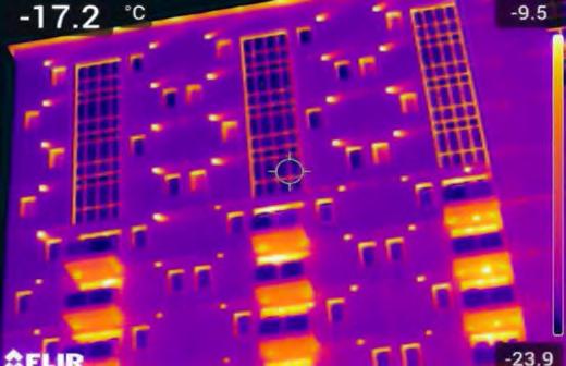
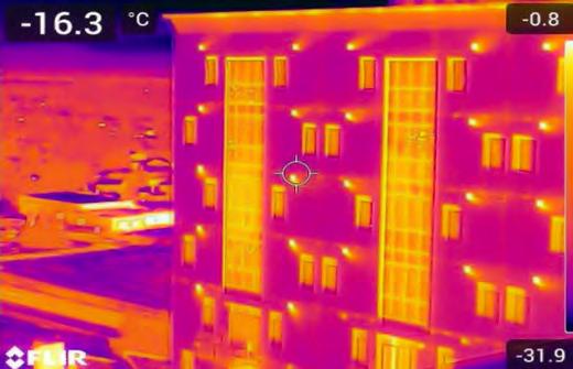
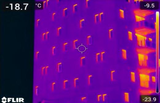
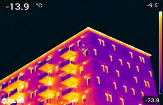
• Continuous insulation (C.I.): By placing the insulation on the exterior of the building, EIFS provides an uninterrupted thermal barrier (C.I.), reducing heat loss in the winter and keeping interiors cooler in the summer. This can contribute to lowering the operational carbon footprint of the building. The effectiveness and value of the C.I. of EIFS is
Figure 1: Halo Towers project thermographic IR scans. Photos courtesy of Christine Asfour-Meta.

displayed by the Thermographic Imaging of the Halo Towers buildings in Winnipeg Manitoba (Refer to Figure 1). The thermographic (IR) scans were conducted during a Winnipeg winter evening with temperatures averaging at -20°C, yet the thermal scans of the façade clearly display a continuous uniform uninterrupted thermal layer broken only by fenestration and/or exhaust vents.
• R-value optimization: EIFS offers the flexibility to achieve a high R-value depending on the type and thickness of the insulation board used. Architects and builders can tailor the system to meet or exceed local energy code requirements. Designers are increasingly selecting an exterior envelope utilizing EIFS with all the thermal resistance on the exterior of the sheathing and leaving the cavity free for other utilities installations, a most effective way to maximize thermal efficiency, as displayed by the thermal scans in Figure 1.
INSULATION TYPES IN EIFS
The choice of insulation material significantly influences the thermal and fire performance of EIFS systems:
1. Expanded polystyrene type 1 (EPS): EPS is the most common insulation material used in EIFS due to its cost-effectiveness and excellent thermal performance. EPS thickness is generally limited
to a maximum of six inches (152 mm) based on fire testing performed by specific manufacturers. Always confirm allowable thickness by reviewing the manufacturer’s fire test data. EIFS utilizing expanded polystyrene (EPS) intended for use in buildings required to be of non-combustible construction may not be permissible unless proven in compliance with Article 3.1.5.5 of the National Building Code of Canada and/ or applicable code requirements. In such cases, EIFS utilizing EPS tested to CAN/ ULC-S134 may be utilized, provided that there are no additional spatial separation constraints, and the applicable codes section allows for more than 10 per cent unprotected openings on the exposing building face. For case specific, it is recommended to consult with the EIFS manufacturer and the Authority Having Jurisdiction (AHJ) on the project.
2. Semi-rigid mineral fiber: EIFS systems utilizing this type of insulation boards are classified as 100 per cent non-combustible cladding, which while it comes at a higher cost, offers several benefits and solutions. Being non-combustible, it offers a higher level of safety and solutions in areas where code spatial separation restrictions allow less than 10 per cent unprotected openings. Additional considerations in the use of
these systems should include overall cost, method of attachment and overall system weight. While thicknesses greater than six inches (152mm) are theoretically possible, most applications are also limited to six inches due to practical considerations.
3. Higher thermal resistance insulation boards: There are several different types of insulation boards which offer higher thermal resistance per thickness than the standard EPS. Most common are higher density EPS (Type 2 or 3), extruded polystyrene (XPS), specialty insulation boards such as graphite and others. Each of these offer higher thermal resistance properties than standard EPS, but they come at a higher cost. These are often used in projects requiring enhanced thermal performance within specific design constraints. Recommended to consult with the EIFS manufacturer specifics as the systems offered may differ in components and composition.
MOISTURE CONTROL
Another key benefit of EIFS is its ability to manage moisture. Modern EIFS systems are typically designed with an integrated drainage layer, referred to as Geometrically Defined Drainage Cavity (GDDC), that allows water to escape, preventing moisture from being trapped behind the system and causing damage to the substrate.
Halo Towers project in Winnipeg, Manitoba.
IMPLEMENTING ACCURACY IN EIFS INTERFACES AND TERMINATIONS
EIFS provides excellent thermal and moisture management, but its long-term performance depends on precise installation, particularly at interfaces and terminations where building components converge. Poor transitions can lead to water infiltration, thermal bridging, and reduced performance, making attention to details critical for long-term durability.
KEY FOCUS AREAS:
• Continuity at secondary barrier: Ensure a continuous tie-in between the EIFS water-resistive barrier (WRB) and adjacent components like window mullions, door frames, and penetrations. This prevents moisture intrusion and ensures incidental water is drained outward.
• Fenestration openings: Seal and flash window heads and sills effectively. Use a two-stage sealant approach with backer rods, sealants, and flashings to protect against moisture and air leakage.
• Roof-to-wall connections: Roof-wall interfaces require precise transition flashings and termination bars for a continuous barrier. Use kick-out flashing to divert moisture outward in high-exposure areas.
• Expansion and control joints: Properly spaced and sealed joints accommodate building movement, preventing cracks or separation. Include a two-stage seal with a WRB back seal and vented front seal.
• Termination at grade: Detail the bottom edge of the EIFS, four to eight inches above grade, with horizontal weep mechanisms to divert moisture. Seal any joints below this level continuously to prevent water intrusion.
ENHANCING DURABILITY WITH HIGH IMPACT RESISTANCE
While EIFS provides excellent thermal and moisture performance, it is inherently more vulnerable to impact damage than traditional cladding systems like brick or concrete. Enhancing impact resistance is essential in high-traffic or impact-prone areas to preserve the system’s long-term integrity.
BEST PRACTICES FOR INCREASING IMPACT RESISTANCE
• Double-layer reinforcement: In high-impact areas, such as near the
ground level, using a double layer of reinforcing mesh within the base coat significantly improves resistance to impact damage.
• High-impact mesh options: Stronger and denser than standard mesh, high-impact mesh is ideal for use in commercial buildings, schools, and other public structures. Applying multiple layers of high-impact mesh substantially improves resistance to damage resulting from heavier impact, which brings EIFS performance closer or equal to the more traditional hard services.
• Protective coatings: Durable topcoats with enhanced resistance to scratching, abrasion, and environmental wear can help maintain the EIFS appearance and performance over time. Features such as hydrophobic finish coatings.
EXTENDING THE LIFE CYCLE AND PERFORMANCE OF EIFS
To fully realize the benefits of EIFS, building owners and managers must prioritize routine maintenance and periodic inspections. Proper care ensures the EIFS continues to perform as intended throughout its life cycle.
MAINTENANCE BEST PRACTICES:
• Regular inspections: Focus on critical areas such as sealants around windows, terminations at roof and grade level, and any signs of impact damage. Early detection of issues allows for cost-effective repairs.
• Cleaning: Routine cleaning prevents the buildup of dirt, mold, or algae on the EIFS surface, protecting its aesthetics and finish durability.
• Prompt repairs: Address any impact damage, cracks, or punctures immediately to prevent water infiltration and maintain the thermal barrier’s integrity.
CONCLUSION
EIFS is a versatile and effective cladding system that offers superior thermal performance, moisture control, and design flexibility, making it an ideal choice for modern construction. Understanding the properties and limitations of insulation materials and focusing on accurate interface and termination details are essential for optimizing system performance. Furthermore, improving impact resistance in highrisk areas, and ensuring consistent maintenance throughout the system’s lifecycle are critical for prolonging the durability and performance of EIFS. This ensures a building envelope that provides long-lasting protection, energy efficiency, and aesthetic appeal, even in the face of evolving environmental and regulatory challenges. ■
Christine Asfour-Meta is a Building Envelope Consultant at Durabond Products Limited, with over sixteen years of experience. She has held senior roles in design and project management, specializing in prefabricated EIFS panels. As a Building Envelope Consultant, she shares her expertise of EIFS best practices with designers, contractors, and applicators.

Exploring Pathways to Improved Housing in First Nations Communities
By Helen Stopps, Maria Milan, and Odel Linetska, Toronto Metropolitan University; Sarah R. Haines, University of Toronto; Natalie Clyke, From Harvest to House; and Becky Big Canoe, Mno Aki Land Trust

Across Canada, there is a widespread housing and infrastructure crisis on First Nations reserves, including a lack of available units, severe overcrowding, unaffordable prices, and inadequate housing conditions. 1 This housing crisis is deeply rooted in the legacy of colonialism, which has led to the widespread disruption of First Nations homemaking through interrelated processes including: the displacement of communities from ancestral homelands, the separation of families, and the imposition of Western ideologies and organizational structures. 2
Housing is widely recognized as a key social determinant of health, and the housing crisis on many reserves has been
recognized as a major contributor to long standing health and socioeconomic inequities.1
Despite decades of government reports, academic literature, and statements from reserves acknowledging the housing crisis, little has changed. The March 2024 Auditor General’s report highlighted that, despite two decades of efforts, significant gaps in housing persist, with 80 per cent of the needs identified by the Assembly of First Nations in 2021 still unmet, making the 2030 deadline to address the housing deficit increasingly unattainable.3 Addressing on-reserve housing challenges is a complex issue influenced by historical injustices, systemic barriers, and logistical difficulties. This article aims to break down these challenges in an accessible
way, providing policymakers, professionals, and everyday Canadians with a clearer understanding of the factors shaping housing efforts and potential solutions, drawing from our recent academic paper “Ten questions concerning First Nations on-reserve housing in Canada,” written in partnership by First Nations housing leaders and researchers from Toronto Metropolitan University and University of Toronto.4
HOW DOES ON-RESERVE HOUSING DIFFER FROM OTHER HOUSING IN CANADA?
On-reserve housing is fundamentally different from other housing in Canada due to legal, economic, structural, and funding challenges. The Canadian federal
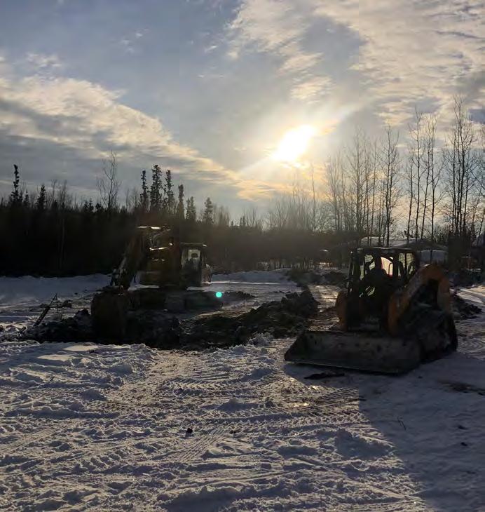
Snowy roads on-reserve in Saskatchewan. Photos courtesy of Sarah Haines.
government primarily acts as the funder for on-reserve housing and First Nations governments manage the development, allocation, and maintenance of on-reserve housing decisions on behalf of their communities. Unlike off-reserve housing, which is subject to municipal and provincial regulations, on-reserve housing falls under federal jurisdiction as part of the Canadian federal government’s fiduciary responsibility to Indigenous peoples. As such, on-reserve housing is often exempt from national building codes unless specified by funding agreements. This creates inconsistencies in construction quality and enforcement.
Additionally, land ownership on reserves is communal under the Indian Act, preventing individuals from using land as collateral for mortgages, which significantly limits homeownership opportunities and private investment in housing.5 As a result, the majority of on-reserve housing is band-owned, meaning that housing decisions, funding allocations, and maintenance responsibilities fall largely under the governance of the band council rather than individual homeowners.
On-reserve housing is primarily funded by federal programs administered by Indigenous Services Canada (ISC) and the Canada Mortgage and Housing Corporation (CMHC). Funding models are highly fragmented and characterized by shortterm, proposal-based allocations, which creates significant barriers to long-term housing planning and infrastructure investment. Proposal-based funding can also unintentionally reinforce disparities between communities. Those with more administrative capacity and well-developed funding applications are more likely to secure financial support, while communities with the greatest housing need often lack the capacity to prepare ‘shovel-ready’ projects and are thus left underfunded.3
BARRIERS TO IMPROVING ONRESERVE HOUSING
Historical underfunding, governance constraints, infrastructure limitations, and restrictive land policies all present challenges which impact housing availability and quality on reserve. In many communities, a lack of skilled tradespeople, geographic remoteness affecting material supply
chains, and ongoing maintenance deficits compound these structural challenges. Additionally, the absence of self-determined housing policies restricts First Nations’ ability to implement long-term housing strategies tailored to their needs.
Many homes on reserves were (and still are) built using standardized designs that prioritize cost-efficiency over cultural relevance, often lacking features such as large communal areas or appropriate ventilation for cooking or high occupancy loads. Housing that does not align with cultural and community needs can contribute to social stress, limit traditional practices, and result in early deterioration of the building envelope.
Further, barriers to improving on-reserve housing are not isolated issues but rather the result of interconnected systemic barriers, where feedback loops reinforce existing challenges, making housing improvements difficult to sustain without systemic intervention. One key example is the cyclical relationship between housing availability and quality, funding
availability, and administrative capacity. A lack of available housing units contributes to overcrowding, which accelerates deterioration and increases maintenance requirements. This ultimately reduces the number of available units due to severe degradation or the need to divert funding away from new construction to maintenance needs, perpetuating a cycle where housing availability and quality continues to decline. In turn, deteriorating housing conditions may further strain limited administrative resources to obtain more funds through proposal-based funding structures, creating a cycle where underfunded communities struggle to maintain and expand their housing stock. Without structural reforms that prioritize self-determined, stable investment approaches, these systemic issues will continue to limit housing improvements on-reserve.
HOW DO WE MOVE FORWARD?
To improve housing on reserves, placebased solutions that embrace local culture, climate, and geography are essential.
Construction begins on new on-reserve housing.
These solutions must emphasize co-development by community members, building scientists, engineers, and policymakers, ensuring that both technical expertise and policy frameworks align with community needs and priorities. While this is not yet the norm, many First Nations initiatives have already demonstrated innovative approaches that successfully integrate cultural and environmental considerations while addressing systemic challenges. In British Columbia, the Great Bear Initiative, an alliance of nine remote First Nations governments, published guidelines on how community members could build energy-efficient and culturally appropriate housing.6 These guidelines emphasize the importance of housing designs that facilitate traditional customs and lifestyles as well as the importance of resident autonomy and engagement to maintain the longevity of housing. Two Manitoba Dene First Nations, Northlands Denesuline First Nation and the Sayisi Dene First Nation, in partnership with researchers from the University of Manitoba, published a toolkit to guide future housing initiatives, integrating Dene cultural values into housing design.7 Through a participatory exchange program, students and community members co-developed designs and detailed
REFERENCES:

renderings of ten proposed housing units which integrated Dene cultural values through material selection, cultural activities, and food security culminating in the Sekuwe (My House) toolkit.7
Currently, our team leads the From Harvest to House program, a collaboration with multiple First Nations communities throughout Canada to co-develop affordable, safe, healthy and resilient housing. This program consists of community knowledge exchange workshops and co-developed research programs to understand the current state of housing
1. D. Patterson and L. Dyck, “On-reserve housing and infrastructure: recommendations for change,” Standing Senate Committee on Aboriginal Peoples, vol. 4, 2015, pp. 1-67.
2. J. Christensen and P. Andrew, “‘They don’t let us look after each other like we used to’: Reframing Indigenous homeless geographies as home/journeying in the Northwest Territories, Canada,” in Indigenous Homelessness, University of Manitoba Press, Winnipeg, MB, Canada, Oct. 2016, pp. 24-48.
3. Auditor General of Canada, “Federal government failing to improve housing conditions for First Nations communities,” Office of the Auditor General of Canada, 2024. https://www.oag-bvg.gc.ca/internet/English/att__e_44454.html.
4. J. S. Lyeo et al., “Ten questions concerning First Nations on-reserve housing in Canada,” Building and Environment, vol. 266, no. 1, 2024. Available: https://doi. org/10.1016/j.buildenv.2024.111544.
5. M. Garneau. The Effects of the Housing Shortage on Indigenous Peoples in Canada: Report of the Standing Committee on Indigenous and Northern Affair. Standing Committee on Indigenous and Northern Affairs (Jun. 2022)
6. D.H. Heerema, “Technical Guideline Development for High Performance Coastal First Nations Housing,” University of British Columbia, 2016.
7. L. Larcombe et al., “Sekuwe (My House): Building health equity through Dene First Nations housing designs,” International Journal of Circumpolar Health, vol. 79, no. 1, 2020. Available: https://doi.org/10.1080/22423982.2020.1717278.
8. A. Marshall and C. Bartlett, “Two-Eyed Seeing for Knowledge Gardening,” Encyclopedia of Educational Philosophy and Theory, 2018. Available: https://doi. org/10.1007/978-981-287-532-7_638-1.
stock by conducting building condition assessments and indoor air quality monitoring. We integrate Two-Eyed Seeing, (Etuaptmumk), a guiding principle emphasizing the integration of Indigenous and Western Knowledge, to foster reciprocal learning and ensure Indigenous Knowledge is valued equally alongside academic methodologies.8 Addressing the on-reserve housing crisis requires continued collaboration, stable longterm investments, and policies that empower First Nations communities to lead the way in designing and implementing housing solutions tailored to their needs. Collaborative research and engineering are a critical pathway for advancing reconciliation. By working together in equitable and reciprocal ways, these collaborations can create meaningful and lasting solutions that not only address immediate housing needs but also support long-term community resilience and self-determination. ■
Helen Stopps, Ph.D., P.Eng is an Assistant Professor in Architectural Science at Toronto Metropolitan University (TMU) and co-lead of the From Harvest to House program. Maria Milan is a Ph.D. student in Building Science at Toron-to Metropolitan University. Odel Linetska is a M.A.Sc stu-dent in Building Science at Toronto Metropolitan University. Sarah Haines, Ph.D., is an Assistant Professor in the De partment of Civil & Environmental Engineering at Univer-sity of Toronto and co-lead of the From Harvest to House program. Natalie Clyke is a Project Manager of the From Harvest to House program and Founder and CEO of Rock-Tree Mgo Construction Materials Inc. Becky Big Canoe is the co-founder of the Mno Aki Land Trust, a member of the Keepers of the Circle and the founder of EnviroNative Training Initiatives.
Wintery road leading into a community.
Aerogel Insulation in Building Retrofits: Maximizing Efficiency with Minimizing Bulk
By Oskar Linkruus, Nicholas Asistores, and Dr. Taofiq Al-Faesly, Algonquin College’s Algonquin Centre for Construction Excellence
Aerogel, famously known for its use on many of NASA’s missions into the most extreme conditions in the universe, has been used as a lightweight and high-performing insulator for almost 100 years. The material, made by removing the liquid in gels and replacing it with gas, creates a solid that is comprised of 97 per cent air. While this process is expensive, technological innovations have made it viable for Aerogel products to be used for residential and commercial construction.
PROJECT BACKGROUND
While aerogel is more affordable now than ever, it still has a high price tag, limiting its economic viability in residential construction. Because of this, this research group will focus on its use in building retrofits. This scope was chosen specifically, as building retrofits of older homes are generally expensive ventures, to begin with, and are often working with limited space to improve the thermal resistance of the assembly.
Two different products, RoVa Shield aerogel coating and Slentite Aerogel panels, were tested to determine aerogel’s viability as an alternative for building retrofits.
RoVa is a South Korean company that produces various aerogel products for construction. The company’s RoVa Shield A wall sample inside the Guarded Hot Box. Photos and graphs courtesy of
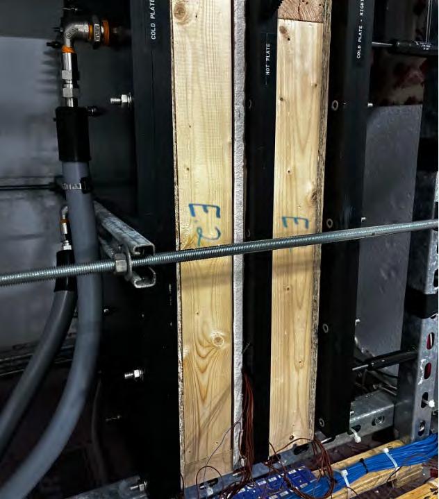
Oskar Linkruus.
While aerogel is more affordable now than ever, it still has a high price tag, limiting its economic viability in residential construction. Because of this, this research group will focus on its use in building retrofits.
Aerogel Insulation Coating product was tested, which has a thermal conductivity of 0.044W/mK. The product also boasts anti-condensation properties and sound dampening, which increases its overall contributions to a more efficient envelope.
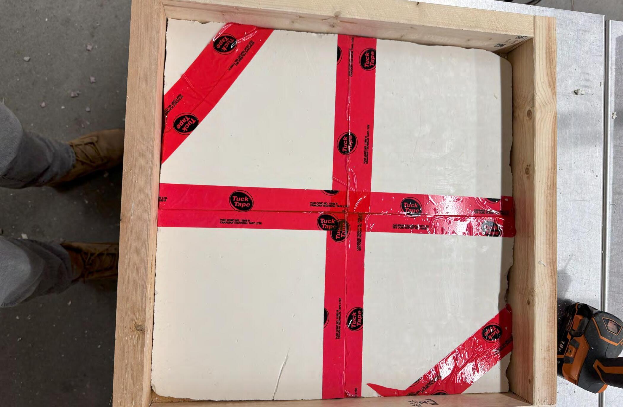
Slentite, designed by Aerogel-it, is a ready to use rigid board insulation with an impressive thermal conductivity of 0.020 W/mK, roughly R-8 per inch. However, the product suffers from a high cost, around $36 per 10.8 inch by 14.2-inch tile, as well as being incredibly fragile. To address the fragility concerns, any broken samples were resecured using Tuck Tape, a practice that, through testing, showed negligible effects on the overall thermal conductivity of the material.
METHODOLOGY
To determine how viable both of these products would be for retrofits, mock wall assemblies were designed to simulate how aerogel products would perform as part of an assembly. These assemblies were
designed to mimic common wall designs found in residential construction. Each wall was custom-made to be two feet wide by two feet tall by four inches deep to fit into the testing equipment.
Two different machines were used for testing. A Fox200 heat flow meter, which is smaller and limited to only eight by eight by four inch subjects, was used mainly for quick tests of one material at a time. The second is a guarded hot plate (right), which tests the two feet by two feet frames. The guarded hot plate is the more important part of the testing as it is capable of testing large samples.
The guarded hot plate works by heating a hot plate in the centre of two identical wall panels, which are sandwiched between two cold plates. This heat difference causes heat flow to occur through the assembly, and sensors then read the amount of heat flow and return a thermal conductivity.
The walls are tested under different conditions, with temperatures ranging
from -15°C to 55°C, with an average difference in temperature being roughly 40°C.
Constructing the assemblies required special considerations to be made due to limitations in terms of depth. Because of this, two by two studs were used in place of a traditional two by four or two by six stud, as it would take up too much space, and thinner extruded polystyrene (XPS) was used when required. The following four walls were tested with the aerogel products.
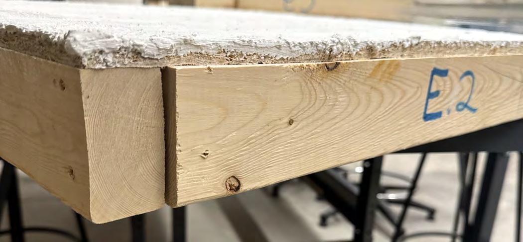
1. Wall cavity with aerogel panel
This assembly is to simulate a traditional stud cavity, albeit quite simplified, with aerogel being positioned on the inside face of the wall, which would be how more insulation would be added in a retrofit project for an existing wall. The wall is four inches thick and is comprised of the following elements:
• Gypsum board (1/2 inch),
• Aerogel panel (1/2 inch),
• Batt insulation (2.5 inches), and
• Plywood (1/2 inch).
Paint on aerogel coating on a wall assembly.

Aerogel Panels, used in place of rigid insulation.
To ensure more comprehensive results, testing of each panel assembly was done in four sets of two temperatures.
2. Wall cavity with XPS
This assembly is designed solely to act as a baseline to compare the first wall, with all components being the same except for the XPS. The wall is four inches thick and is comprised of the following elements:
• Gypsum board (1/2 inch),
• XPS (1/2 inch),
• Batt insulation (2.5 inches), and
• Plywood (1/2 inch).
REFERENCES:
1. ThermalBlok, “What is Aerogel?” Available: https://www.thermablok.co.uk/ site/wp-content/uploads/2018/03/ What-is-Aerogel.pdf.
2. RoVa Shield, “roVa Shield Insulation - roVa Shield,” roVa Shield - roVa® Shield Aerogel Insulation Coating, 2018. https://rovashield.com/rova-shield-insulation/ (accessed Oct. 03, 2024).
3. Aerogel Technologies LLC, “BuyAerogel.com | SLENTITE® Aerogel Panels for Construction,” Buyaerogel.com, 2024. http://www.buyaerogel.com/ product/slentite/ (accessed Oct. 03, 2024).
3. Roof assembly with aerogel coating
The roof assembly was chosen as applying the coating to the roof sheathing was one of the main usage cases advertised by the manufacturer. The roof is four inches thick and is comprised of the following elements:
• Gypsum board (1/2 inch),
• 2x2 “joists” (1.5 inch),
• Batt insulation fill (1.5 inch),
• XPS (1/2 inch),
• Plywood (1/2 inch),
• Aerogel coating, and
• Roofing felt paper.
4. Roof assembly without aerogel coating
This roof, similar to the case of assembly number two, is simply a baseline for the aerogel roof (number three), as it will provide a reference value to measure the aerogel’s efficiency. The roof is four inches thick and is comprised of the following elements:
• Gypsum board (1/2 inch),
• 2x2 “joists” (1.5 inch),
• Batt insulation fill (1.5 inch),
• XPS (1/2 inch),
• Plywood (1/2 inch), and
• Roofing felt paper.

By using the results of these compacted assemblies, conclusions on the overall effectiveness of the walls can be determined by scaling up the walls to match common building dimensions.
RESULTS
To ensure more comprehensive results, testing of each panel assembly was done in four sets of two temperatures, roughly 40 apart, increasing by 10 with each interval: from -15 and 25 at the lowest set point to 15 and 55 At the highest set point. As assemblies were designed to have each assembly containing aerogel compared to a baseline assembly, the data is presented as such.
The advantage of using aerogel panels within the wall cavity over XPS is clear, with the average R-value increase being 0.700. It's worth noting that the result in the first data set point we received in the comparison for the roof assembly was a statistical anomaly that skews the data against the effectiveness of the aerogel coating. Further testing is slated to be performed within the upcoming weeks. If the first set point is included, the average R-value increase is 0.122 , whereas if the first point is excluded, that value almost quadruples to 0.483. ■
Oskar Linkruus is a third-year student in Algonquin’s Bachelor of Science, Building Science Honours program. Nicholas Asistores is a third-year student in Algonquin College’s Building Science Honours program. Both Nicho-las and Oskar have been working on this aerogel research project since September of 2024 alongside his Professor, Taofiq Al-Faesly, and fellow student, Oskar Linkruus. Dr. Taofiq Al-Faesly is a distinguished educator and en-gineer with over 30 years of experience in academia and in-dustry, and is a Professor at Algonquin College’s Algonquin Centre for Construction Excellence (ACCE) and a Principal Engineer at Alfa Alliance Engineering Inc.

Sealing the Gaps: Preventing Window-Wall Water Woes
By Javeriya Hasan, Emily Saleh, and Terrence Holder, 30 Forensic Engineering, and Austin Todd, Evergreen Building Science
The increasing frequency of extreme climatic events has heightened the risk of window failures. These failures severely impact building performance, durability, and occupant health and bring with them significant financial costs. The 2012 Toronto’s Future Weather & Climate Driver Study shows that annual weather between 2000-2009 experienced a maximum rainfall amount of 66 mm in one day. This is predicted to increase to 166 mm between the years 2040-2049. As this timeframe is within the expected life expectancy of current window installations, our current practices should meet future expectations. Installations that were previously adequate may now succumb to wind-driven precipitation, causing premature water infiltration. Investigating the causes of such failures is often challenging due to the involvement of multiple collaborators in window design, manufacturing, and installation.
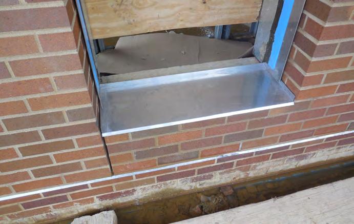
The failure timeline of a rainscreen window itself can range from fifteen to twenty years, depending upon the type and manufacturer’s rating and specifications. However, water leakage may not originate solely from the failure of the window itself, as other factors can contribute to window failures. Understanding the causes of these failures is vital to preventing them. Other than failures originating in windows themselves, it is important to account for the influence of the interface between the window frame and the rough opening that may lead to water ingress (see Figure 1). For rainscreen wall systems, it is important to recognize that an effective drainage of water can occur only with a well-installed and integrated secondary plane at the window-wall interface.
INTERFACE ISSUES LINKED TO WINDOW FAILURE
At the window-wall interface, proper installation entails ensuring the rough
opening is level, plumb, and the window is sized correctly to fit into the opening with the necessary draining and sealing materials. A key component is the integration of flashing systems, which guide water away from the interface. Ideally first, a sloped sub-sill flashing with a back-dam is installed to prevent water from pooling at the base. Next, a jamb and head flashings are installed in a shingle-lap fashion to create a continuous drainage path. The window is then set into the opening with a bedding sealant along the perimeter, ensuring a watertight seal. Internally, a low-expansion foam sealant or foam rope is applied to fill the gap and provide a bit of R-value while allowing for controlled drainage. Either an approved caulking or tape will provide the
modulus needed in the transition joint allowing for some movement and keep water from penetrating to vulnerable areas. Proper pathways for water drainage are essential and include sill and jamb flashings, weep holes, or drained cavities. Weep holes may be inadvertently sealed or omitted due to improper sealant application, preventing water from escaping. A lack of slope or an incorrect slope in the cavity can direct water toward the interior rather than away from the rough opening. Additionally, failing to identify the intended drainage plane and obstructing it with cladding construction or positioning weep holes incorrectly can prevent proper water egress. Furthermore, installation errors, such as the use of incompatible flashing materials
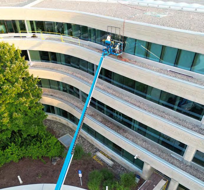
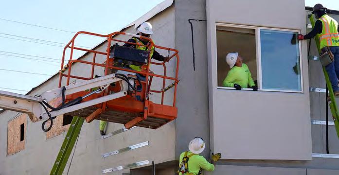
Figure 2: An exterior view of the boom lift used to do water penetration testing. Photos and diagram courtesy of Austin Todd..
and damaged flashing membranes, are frequently due to poor sequencing during the installation of the weather-resistant barrier (WRB). Interface components like poorly site installed heel and or toe beads foam sealants, tapes, and gaskets can lose adhesion if applied to surfaces that are not adequately prepared (see Figure 2). Differential movement between the window and wall, such as frame deflection due to wind pressure, or forces in opening and shutting windows can stress the flashing membrane or seals, leading to leaks.
Penetrations through the interface, for instance, a cable or pipe run beside a
window, may be added after window installation, causing holes to be poked in the water barrier. If these holes are not repaired with sealant or flashing, they become locations where moisture or water ingress can occur. Additionally, contaminants on surfaces (dust, wet wood, cold temperatures) during installation can prevent proper adhesion of membranes, tapes, and sealants, effectively nullifying the waterproofing even if installed per detail. Therefore, proper prep work is paramount. Forensic analyses commonly link window leaks to incorrect flashing issues, particularly at corners and wall windows

for air and water infiltration: Discrepancies between design specifications and construction practices, such as misaligned or mis-lapped flashing, can result in water infiltration, especially during heavy storms. If corner patches or end-dams at the sill are omitted, water can leak at the window frame corners even if the rest of the sill is flashed. Such mistakes may not be obvious after construction, since the assembly is covered by trim or cladding, allowing leaks to go undetected until damage appears later.
Sometimes inconsistencies among different construction drawings – for example, one plan omitting a flashing that another plan assumes will be there or the assumption that the contractor will deal with it –often lead to leakage at the perimeter once built. Design teams should perform thorough detail coordination or engage thirdparty design reviews to catch discrepancies early. For instance, the design might call for a backer rod and sealant joint around the window, but a contractor might skip the backer rod or use spray foam instead. In another scenario, a specified head flashing might be left out because the installer assumed caulk was “good enough.” These deviations can compromise the drainage design.
Another factor is construction site errors, like damage to installed flashing or windows. A worker might damage the flashing membrane or WRB when installing adjacent materials (siding, stucco, drywall) and fail to ensure its repair, either out of negligence or unknowing that damage occurred.
EXISTING TESTING STANDARDS
In North America, two primary standards are used to evaluate installed windows for air and water infiltration:
• ASTM E783: Field Measurement of Air Leakage Through Installed Exterior Windows and Doors.
• ASTM E1105: Field Determination of Water Penetration of Installed Exterior Windows, Skylights, Doors, and Curtain Walls by Uniform or Cyclic Static Air Pressure Difference.
These standards ensure compliance with performance criteria, such as air leakage and water penetration limits, as per the Canadian Supplement to the North American Fenestration Standard
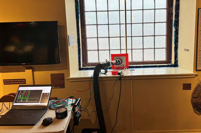
Figure 1: An interior view of the set up used for water penetration testing. Photos and diagram courtesy of Austin Todd.
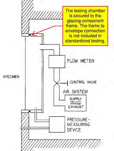
(A440S1-19). The ASTM E1105 test uses a pressure chamber to simulate wind-driven rain pressure, covering the entire window assembly, including joints, seals, and transition areas. The pressure control system creates a static air pressure difference, forcing water to penetrate any weaknesses. Inspectors monitor water infiltration, focusing on areas like corners, joints, and frame perimeters. However, these tests typically exclude the transition joint between the window and the rough opening unless previously agreed on by the building envelope consultant as the transition joint would be a modification to the testing standards.
As shown in Figure 1 of ASTM E783: Standard Test Method for Field Measurement of Air Leakage Through Installed Exterior Windows and Doors, the testing chamber is secured to the glazing component’s frame, excluding the rough opening (see Figure 3), just like it was tested in the lab using ASTM E283. Although current design standards seldom specify rough opening performance, this compliance test verifies that the installed glazing meets specified performance criteria. If the component fails, typically the manufacturer and/or installer is responsible for remediation to ensure compliance. This connection should resist air leakage and water penetration at the design wind loads for the region, as wind-driven rain is the primary cause
of infiltration. Additionally, it should be installed to meet or exceed the expected life cycle of the window component.
Shifting from compliance testing to performance testing by incorporating construction-phase quality control of the rough opening connection (i.e. via mock-ups and oversight during construction) is a proactive investment in a building’s durability and long-term performance. The cost of addressing air and water seals during construction is negligible compared to post-occupancy repairs. Compliance testing merely verifies that glazing manufacturers and installers deliver the specified product, while performance testing ensures the building owner is delivered a project that does not leak. However, it is also not uncommon for mock-ups to be missed in the process, leading to undetected deficiencies that compromise long-term performance and necessitate costly remediation after occupancy.
THE WAY FORWARD
Importantly, lab ratings of windows prove the product’s capability, but properly executed field installation ensures those same levels of water resistance for the building. Minimizing window failures demands cooperation among all collaborators, including architects, contractors, manufacturers, and envelope consultants. As forensic case studies reveal that water leakage commonly results from multiple factors, particularly at interfaces with walls
and roofs, pinpointing the water entry location(s) is complex due to interactions between building components, and lack of access to control layers after project completion. Priority should be placed on identifying interface areas and resolving potential issues to prevent costly failures. From a macro standpoint, the window-wall interface merits special attention that should be viewed as an inherent weak spot in the building, which could lead to water intrusion and merits special attention on getting correct from the start.
As industry expectations evolve, there is an opportunity to advance standardized education on best practices. Field testing presents an avenue for learning, as it can expose deficiencies and allow them to be corrected. By demonstrating areas for improvement through field testing, tradespeople not only contribute to better-performing buildings today but also apply this knowledge to future projects – ultimately enhancing the quality and durability of the built environment. ■
Dr. Javeriya Hasan is an Associate at 30 Forensic Engineering, specializing in Civil and Structural Engineering and Building Science. Emily Saleh is a Senior Associate with 30 Forensic Engineering’s Civil and Structural Engineering Group, specializing in Building Science. Terrence Holder is the Technical Director of the Civil and Structural Engineering and Building Science and Building Envelope groups at 30 Forensic Engineering. Austin Todd is the Founder and President of Evergreen Building Science Inc., and a building science and sustainability professional.

Figure 3: General arrangement of air leakage test apparatus.
Making Transitions
By Julie Szabo and Jason Sanchez, Wiss Janney, Elstner Associates, Inc.
The air and water control layers are fundamental to building enclosure performance. Within many commonly used exterior opaque wall assemblies, the air and water control layers are provided by a single material with a combined function, indicated as an air and water barrier (AWB). When integrating glazing into the wall assembly, transitions between the AWB and fenestration1 assemblies are created. It is at these transitions where the majority of post construction issues originate. As such, these transitions need to be carefully designed and coordinated during construction, since these transitions typically include the work of multiple installers. Discontinuities between the AWB and the fenestration can result in air and water infiltration to the building interior.
Like many building materials, selection of fenestration systems for specific wall assemblies is a process in which performance characteristics such as structural capacity, the resistance to air infiltration, water penetration, and thermal attributes are evaluated along with aesthetics and cost. However, the integration of the system(s) under consideration with the adjacent exterior wall assembly is often overlooked in the selection process.2 Once the fenestration is selected, the specific detailing of the AWB and fenestration transition can be complex, especially on projects where multiple types of fenestration are used. Often in the contract documents, both the fenestration assembly and the AWB are represented schematically with the specific details being refined during the submittal
process when coordination between the trades occurs. Since this transition is critical to enclosure performance, the focus on integration of the AWB and fenestration should begin during design so it is not an afterthought during construction which can potentially increase time and costs.
As a starting point to design and install the AWB transition to different fenestration assemblies, the function of the fenestration type, with respect to air control and water management, should be understood. This will determine where and how to provide the continuous air and water seal. The continuous seal should be located at the “wet-dry line” of the fenestration assembly; the location of which is a function of the air and water management within the fenestration type.
The following concepts should be followed to provide a continuous air and water seal at the transition between the AWB and fenestration:
• Identify the available substrate for installation of a continuous air and water seal,
• Determine the material to be used at the transition,
• Align the air and water seal at the wet-dry line of the fenestration assembly,
• Confirm the access and installation method of the air and water seal, and
• Verify continuity.
CURTAIN WALL
A curtain wall assembly is a non-loadbearing wall assembly that is hung on the
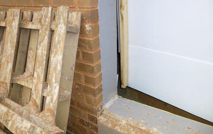
Sheet metal cavity closure used to close off the wall cavity and provide an extension of the AWB to which to seal the fenestration. Photos courtesy of Julie Szabo.
structure of the building, usually spanning multiple floor levels at a façade3 or used in punched openings, typically in mid- to high-rise buildings. There are two main types of curtain walls; stick-built which are field constructed; and unitized which are shop fabricated in units and fit together onsite. Both types of curtain walls share the same air and water management concepts, which occurs within the glazing pocket where the insulated glass unit (IGU) is located. Water is managed in each glazing pocket and is weeped to the exterior. The weeps allow air into this area. As such, the wet-dry line of a curtain wall assembly occurs at the interior edge of the glazing pocket in alignment with the interior surface (surface number two) of the IGU and the edge of the solid frame extrusion supporting the IGU. This area is commonly referred to as the “shoulder” of the curtain wall frame. It is at this location where the continuous air and water seal between the curtain wall and AWB should occur.
In the most basic form, the air and water seal can consist of a sealant joint between the shoulder of the curtain wall frame and the AWB. Installation of this detail requires that the AWB and underlying adjacent wall assembly are in alignment with the curtain wall shoulder to provide adjacent substrates for the sealant joint. Where this alignment is not possible (or where obstructions exist limiting access), the air and water seal can be achieved by using a preformed transition membrane, sealed onto the edge of the frame inside the glazing pocket. The transition sheet material used for this purpose must be able to span the gap between the curtain wall and AWB, unsupported, and manage the expected movement at this joint. Preformed silicone sheets have been developed by several manufacturers for this purpose. As with any installation, compatibility and adhesion of materials should be confirmed.
STOREFRONT SYSTEMS
Storefront assemblies (storefront) are typically used in single story, floor-to-ceiling applications in non-residential areas of buildings, commonly as commercial entrances and windows. Like a curtain wall, air and water management in this system generally occurs within the glazing pocket. However, these assemblies typically use
open channel frames with interconnected glazing pockets that can allow air and water within the assembly to the interior most edge of the frame. Any bulk water or moisture within this area is collectively drained down the mullions to a sub-sill where it weeps out. As such, the wet-dry line for storefronts is located at the interior edge of the storefront frame.
Although the wet-dry line is at the interior (glass) side of the storefront frame, storefront frames are typically an open channel which is not designed to manage water. The AWB transition should be configured to close off this side of the frame and prevent air and water from entering this space from the adjacent opaque wall. This can be achieved by providing the continuous seal between the AWB and the exterior edge of the storefront frame, however it is dependent on the location of the storefront within the wall assembly and the type of cladding. Commonly, a closure is required, that is integrated with the AWB to align the AWB with the exterior edge of the storefront frame and provide a substrate for this continuous seal.
SUPPLEMENTAL SEALS
Redundancy of the air and water seals at these transitions can also be provided. Although not performing the primary function of air and water control, a seal between the fenestration frame and cladding can be provided to shed water and provide protection from bulk weather while concealing the primary seal. On the interior, a
supplemental air seal can also be provided between the frame and AWB to prevent interior conditioned air from reaching the edge of the frame bordering the thermal break where condensation can occur. This is typically more critical in cold weather construction. ■
Julie Szabo is an Associate Principal at Wiss, Janney, Elstner Associates, Inc., with over 20 years of experience in building science and building enclosure consulting. Jason Sanchez is a Senior Associate at Wiss, Janney, Elstner Associates, Inc., with 18 years of experience in building enclosure consulting where his work focuses on project management and technical advisement.
REFERENCES:
1. Per the Fenestration & Glazing Industry Alliance (FGIA), fenestration includes “Openings in or on the building envelope, such as windows, doors, secondary storm products, curtain walls, storefronts, roof windows, tubular daylighting devices, sloped glazing and skylights, designed to permit the passage of air, light, or people.” It is at the perimeter of these various elements where the transition between the opaque wall and the fenestration assembly occurs.
2. Slaton, Deborah, and David S. Patterson. “Integrating fenestration with the wall: Failures.” The Construction Specifier: The Official Magazine of the Construction Specifications Institute (CSI). https://www.constructionspecifier.com/integrating-fenestration-with-the-wall/.
3. AMAA
Membrane cavity closure used to close off the wall cavity and provide an extension of the AWB to which to seal the fenestration.
Propelling Sustainable Building Restoration with Deep Energy Retrofits in Canada
By Chuck Bundrick, Tremco Construction Products Group
As the global focus on sustainability and climate change intensifies, Canada is experiencing a new trend in building restoration- deep energy retrofits. Buildings are the third largest contributor of greenhouse gas (GHG) emissions in Canada after the oil and gas and transportation sectors.1 Therefore, existing structures, including single-family homes, multi-unit residential buildings (MURBs) and commercial buildings, have been targeted for energy-conscious renovations. A deep energy retrofit is achieved when renovation activities reduce a building’s site energy usage by at least 40 per cent.2
With legislative measures stimulating the adoption of decarbonization initiatives, local programs are incentivizing and supporting owners, architects and contractors through the implementation of deep energy retrofits. Likewise, the construction and design industries seek to ease this process for stakeholders by introducing sustainable building technologies that accomplish these retrofits more efficiently. One such solution is the use of prefabricated exterior wall panels to reclad buildings with improved insulation, thermal performance, airtightness and watertightness.
This article reviews the drivers behind energy performance regulations, how the built environment factors into reaching key milestones and tactics to streamline the adoption of deep energy retrofits.
SETTING THE STAGE FOR WORLDWIDE ENERGY CONSERVATION AND REDUCTION
Designated as a global emergency by the United Nations,3 the pollution from greenhouse gas emissions, which include carbon dioxide, methane and other harmful gases, has led to substantial, often irreversible, environmental damage.
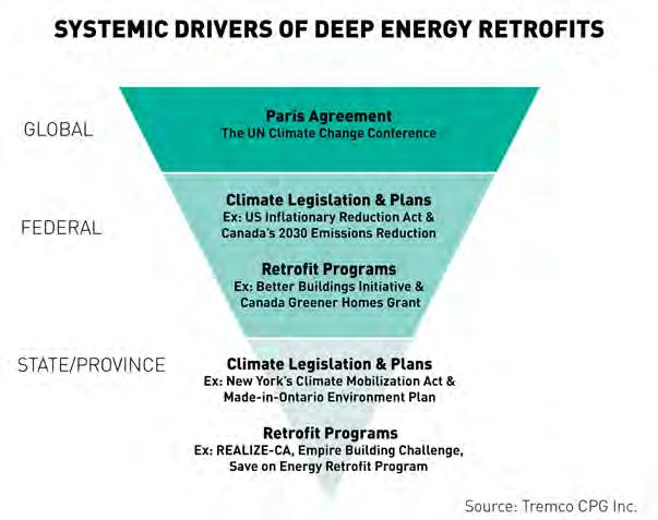
In 2015, the historic Paris Agreement was ratified by world leaders at the UN
Climate Change Conference to commit to collective climate action to reduce emissions and limit the Earth’s temperature increase to “1.5°C above pre-industrial levels.”3 Today, 195 parties have signed onto this legally binding international treaty, but to attain its goals, global greenhouse gas emissions need to reach net-zero by 2050. Net-zero means cutting emissions to as close to zero as possible and substituting coal, gas, and oil-powered energy sources with more renewable energy sources, such as wind and solar. Worldwide, the Paris Agreement has triggered an increase in sustainable policies. In 2021, the Canadian Net-Zero Emissions Accountability Act went into effect “to reduce GHG emissions by 4045% per cent below 2005 levels by 2030 and to achieve net-zero emissions by 2050.”1
To assist with the practical and financial implications of these measures, national, province and city-based strategies and programs have begun to take shape. For example, the Canada Green Buildings Strategy (CGBS),1 the Better Buildings Partnership in Toronto,4 Better Homes Ottawa,5 and Energize Vancouver6 offer a variety of resources, rebates, grants and loans to stakeholders across residential and commercial buildings.
HOW BUILDINGS IMPACT CARBON EMISSIONS
Building renovations, especially in densely populated areas, are pivotal to reducing both embodied carbon and operational carbon emissions in the construction sector. The term “embodied carbon” refers to the sum of carbon dioxide emissions tied to material extraction, manufacturing, transportation, and installation throughout the construction process and lifecycle of a building. ‘Operational carbon emissions’ are those generated throughout the building’s ongoing use and maintenance, such as from heating and cooling. While energy conservation throughout new construction is important, it has been found that retrofitting occupied buildings saves between 50 and 75 per cent of lifecycle carbon emissions compared to constructing the same structure new.7
In either case, tactics to reduce embodied carbon in building design and construction extend to reducing waste, incorporating recycled or reclaimed products, and using low-carbon, carbon-neutral or carbon-storing materials. Together, the tangible improvements of deep energy retrofits can lead to dramatic urban transformation.
Deep energy retrofit panel installation. Photo courtesy of Tremco CPG Inc.
THE IMPORTANCE OF THE BUILDING ENVELOPE IN DEEP ENERGY RETROFITS
Decarbonization at the rate needed to hit the global milestones requires drastic changes to the aggregate building stock. Minor building repairs and upgrading interior elements, such as lighting, mechanical systems and appliances, are helpful, but are not sufficient to meet international standards in the given timeframe.
Deep energy retrofits take a whole-building lens and involve these advancements plus more extensive changes to the exterior shell of a building and incorporate more renewable energy sources. These adaptations look to optimize all the structure’s unique facets, which vary depending on the building typology, location, construction materials and occupancy. The goal of most retrofits is to execute these improvements in a short period of time to minimize the time, space, labour and money spent.
Recognizing the importance of the entire building envelope as the primary barrier between the interior and exterior conditions is critical to the success of a deep energy retrofit. The external building performance impacts the ultimate effectiveness of the structure’s internal heating and cooling mechanisms. The positive environmental impacts of an energy-efficient HVAC system are essentially negated if the building envelope has significant thermal bridging and air leakage.
A high-performance building envelope is dictated by numerous factors, including the wall systems’ thermal mass, quality and continuity of insulation, airtightness, and watertightness. The National Institute of Standards and Technology (NIST), in partnership with ASHRAE, Oak Ridge National Laboratory (ORNL), and the Air Barrier Association of America (ABAA), posits that improving airtightness is one of the most cost-effective ways to decrease energy loads.8
PANELIZED CLADDING SOLUTIONS TO SPEED ENERGY SAVINGS
To alleviate the threat of wasted energy in the building enclosure, deep energy retrofits can incorporate exterior panelization for an air- and water-tight façade with increased R-value. Exterior wall panels are prefabricated in a factory under controlled settings for greater quality control, so they
can be shipped to the jobsite and mounted on the building whenever the project is ready. The off-site assembly method promotes year-round restorations and minimizes weather-related delays.
Over-clad systems, often comprised of a framing material, drainage, insulation and a durable architectural finish, can even be installed without removing the preexisting cladding. Once brackets are mechanically attached to the vertical slab in the field, the panels are ready to be hung in place. Then, installers mount and detail the window assemblies. Expansion joints are sealed with
a flexible thermal barrier which can accommodate any slight building movement. This speed enables buildings to achieve an airand water-tight envelope almost immediately after hanging the panels.
Prefabricated wall panels can eliminate harmful thermal bridging, maximize operational efficiency, decrease occupant disruption, and reduce on-going utility costs for the owner. The wall systems also have infinite artistic possibilities, giving architects complete design versatility to refresh the building’s appearance to the owner’s desired aesthetic.


CONCLUSION
Deep energy retrofits offer a promising solution to lowering the greenhouse gas emissions produced by Canada’s building stock to meet objectives set by the Canadian Net-Zero Emissions Accountability Act. However, achieving decarbonization and net-zero with existing structures requires numerous factors to fall into place.
In addition to the holistic exterior and interior building approach necessitated by retrofits, education, financial and logistical viability, and buy-in from stakeholders are critical. The deep energy retrofit strategy spans single-family and multi-unit residential and commercial sectors, so design and construction professionals, building owners, community leaders and households are all involved.
High-performance building materials, like prefabricated exterior wall panels,
streamline the actual retrofit, while national and regional programs provide crucial upfront support and economic incentives aimed at addressing the distinct needs of local communities. Together, these efforts demonstrate how collaboration between policymakers, construction industry professionals and building owners can drive impactful change. By reducing emissions from the built environment, Canada takes an essential step toward sustainability and combating climate change. ■
Chuck Bundrick, CSI, LEED GA, is a Key Account Executive – Commercial Construction and Renovation at Tremco Construction Products Group. He is a veteran of the exterior insulation and finish system (EIFS) and construction industry with nearly 30 years’ experience in senior sales and business management roles. He assists a team of professionals that help building owners, architects, and their design and engineering consultants consider prefabricated solutions for their projects.
REFERENCES:
1. Government of Canada. “The Canada Green Building Strategy: Transforming Canada’s buildings sector for a net-zero and resilient future.” https://natural-resources. canada.ca/energy-efficiency/building-energy-efficiency/canada-greenbuildings-strategy-transformingcanada-s-buildings-sector-net-zeroresilient-future.
2. U.S. Department of Energy. “Deep Energy Retrofits.” https://natural-resources.canada.ca/energy-efficiency/building-energy-efficiency/ canada-green-buildings-strategytransforming-canada-s-buildingssector-net-zero-resilient-future.
3. United Nations. “Climate Action: The Paris Agreement.” https:// www.un.org/en/climatechange/ paris-agreement.
4. City of Toronto. “Better Buildings Partnership.” https://www.toronto. ca/services-payments/water-environment/net-zero-homes-buildings/better-buildings-partnership/.
5. BetterHomes Ottawa. https://betterhomesottawa.ca/.
6. City of Vancouver. “Energize Vancouver.” https://vancouver.ca/ green-vancouver/energize-vancouver.aspx.
7. RMI. “Transforming Existing Buildings from Climate Liabilities to Climate Assets.” https://rmi.org/ insight/transforming-existing-buildings-from-climate-liabilities-to-climate-assets/.
8. Shrestha, Som, et al. “Online Airtightness Savings Calculator for Commercial Buildings in the United States, Canada, and China.” https:// tsapps.nist.gov/publication/get_pdf. cfm?pub_id=920497.

Figure 1: Systemic Drivers of Deep Energy Retrofits. Courtesy of Tremco Construction Products Group.
MEMBERSHIP APPLICATION

MEMBERSHIP YEAR: JUNE 1ST-MAY 31ST
Membership opens the door to so much more.
More learning: Conferences, technical forums, and field trips.
More people: architects, engineers, educators, manufacturers, and contractors.
More opportunities: Construct Canada, dinner meetings, and social events.
In 2025 OBEC rebranded to the Building Science Association of Ontario (BSAO) with the mission to advocate for building science and provide quality education and forums for collaboration for members to network and increase their technical knowledge. Our vision is to ensure we are the gold standard in building science education and professional networking.
Guided by the Board of Directors, BSAO is focused on delivering:
• Information forums for the exchange of ideas and information on building science
• Access to current technical information and best practices
• Educational programs for the benefit of the building community
• Guidance on current trends and issues to the research and development community
• Recommendations regarding improvements to codes and standards
Corporate Membership: A Corporate Member may be named as such if the member is a corporation, an individual to act as its representative at any meeting of members of the Corporation must be named as the corporation's main representative. A Corporate Member is entitled to five named persons to be listed in the membership database to receive all society notifications as well a copy of Pushing the Envelope magazine. All company employees are eligible to receive the member rate for events.
Individual Membership: An Individual Member may be designated as such if the member is an individual person.
No-Fee Student Membership: A student is an individual attending a recognized building science program at a college or university program full time.
Join BSAO and join over hundreds of other like-minded people in your industry. Submit your membership application today and open the door to so much more! https://bsao.ca/membership/join-bsao.