DTU


Introduction
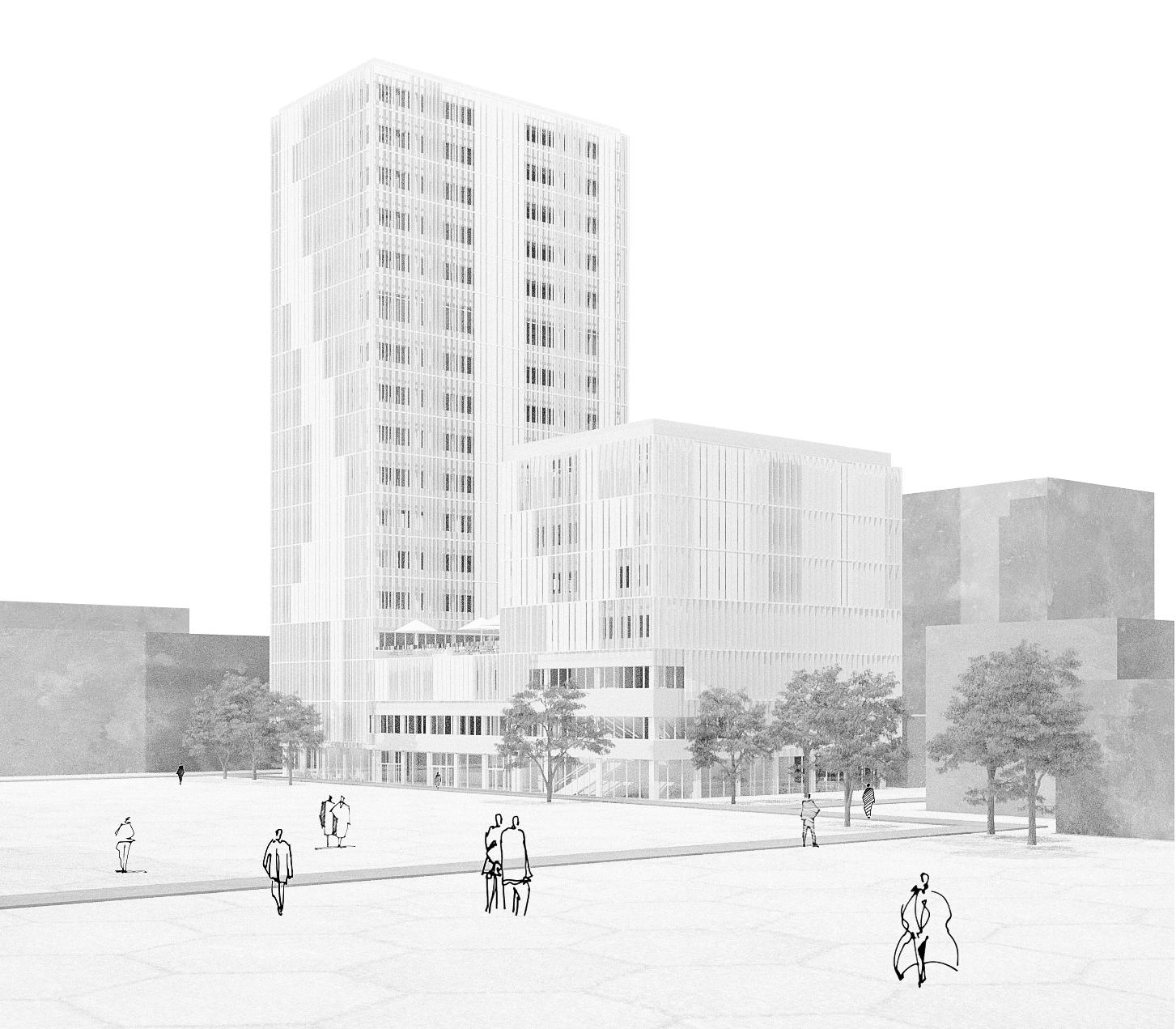
On a 31m x 58m site at Fysikvej, 2800 Lyngby an up to 70m high-rise buidling should be developed. The property is located on the campus of the Technical University of Denmark (DTU) north of Copenhagen.
The main purpose of the building is office use (63% of the total net GFA). Overall, the building aims to be accessible, functional and keep a connection to the campus. The sustainability of the building will be assessed using the DGNB framework. The aim is to achieve a Gold-certification.
Construction must be completed in 30 months and within a budget of 35.000 DKK/m2.
The design team has worked towards complying with the Danish Building Regulation, the DTU Strategic Campus Plan and Lokalplan, technical requirements and the client satisfaction, offering an open, elegant, functional and flexible building that intends to inspire all its users and visitors.
The architeture team has collaborated closely with structural, fire and MEP experts to design the best building possible. The planning process is based on constant feedback cycles and strong interdisciplinary dialogue.
Historic Background
Construction work for the campus first started in the 1960s. Back then, the architects Eva and Nils Koppel were commissioned to design the „University in the forest“. Today, the 106-hectare area houses a vast variety of green spaces and more than 100 buildings, including student dorms, libraries and teaching units. Yellow brick facades are a typical characteristic to the campus. Most buildings are 50m or 100m long and up to three stories (12m) high.
Adjacent Building
The site is located in the center west of the campus next to building 310 (DTU Energy), which has recently been finished. The six story building (30m high) houses laboratories and study spaces. The perforated facade breaks with the traditional DTU building style and is designed as patterns of brown coppery sections.
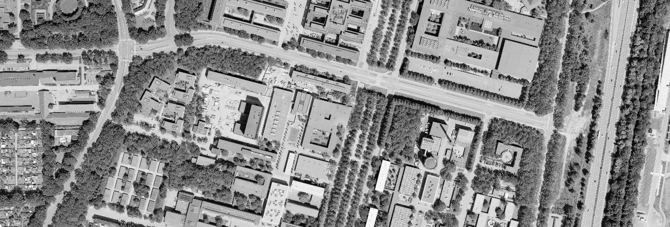
figure ground plan of DTU Campus satellite image of the site
To develop a first understanding of the plot and its conditions, a „by-hand approach“ was utilized to test a variety of potential building volumes through sketches. Several shapes and combinations were considered. Next to the architectural quality, key influencing factors were issued by PM (GFA maximisation) and MEP (daylight efficiency), see details on the left. Problems and opportunities were quickly identified and optimised in an integrated design process and through various discussions.

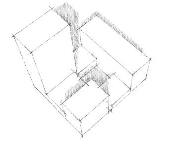

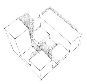
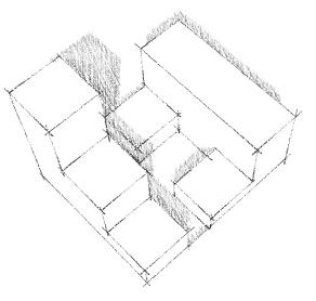

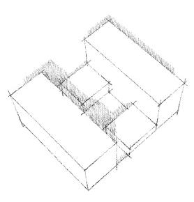
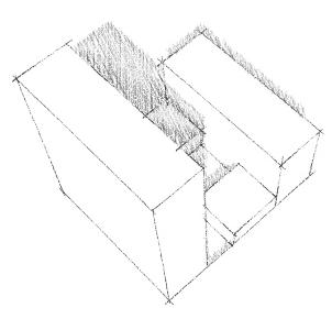

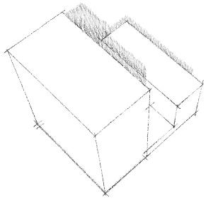
To give one example: originally, the architectural team argued towards a max. 30m-high building, since no building on campus exceeds this hight. However, in discussion with PM, it quickly became clear that the targeted KPIs could not be met with 30m (far too little GFA). Thus we started looking for a compromise. Simultaneously a detailed site analysis was performed, which investigates urban planning rules, daylight factors, green areas and existing mobility networks (see next page).
Different compositions were evaluated and evolved according to both fixed requirements (e.g. space requirements) and additional design decisions (e.g. outdoor rooftop). The insights gathered were then summarized and ultimately, based upon the learnings of the two studies, a final design proposal was determined.
The landscape is part of the university‘s identity and provides a scenic and varied campus environment. DTU Strategic Campus Plan particularly stresses the importance and positive impact of green spaces on learning, well-being, stress reduction and climate change.

The north side of the property abuts a grass verge. All other adjacent areas are sealed. In order to carry forward the overall campus theme, we propose including new, public green spaces as part of the property development.


Great emphasis is placed on getting to Lyngby Campus in an eco-friendly, enjoyable and safe manner. In 2025, the Greater Copenhagen Light Rail will be completed, linking the campus with the city and S-trains.
Today the site is mainly accessed from pedestrians and bikes coming from campus (east) or Lundtoftevej (west). The bus lines 300S, 400S and 180 stop along Anker Engelunds Vej, a five minute walk north of the property. A parking lot is located on the opposite side of the street. However, DTU is currently transforming the entire campus into a car-free zone. Multi-story car parks at the periphery function as arrival points and are directly connected to the pedestrian and bycicle network.
The site is elongated facing north. Accordingly, the two main facades face west and east (approx.). It should be further noted, that the neighbouring building 310 casts a shadow on the plot in the morning hours before noon.

The plot is 31m deep. If the whole site were developed, many areas in the interior would not be exposed to sufficient daylight. It is therefore advisable to instead think in terms of several smaller volumes (this is also in line with the results from the volumetric analysis, previous page). Special attention must be paid to avoid overheating and sunshading.
Architecture at DTU is based on the master plan from the 1960s. New buildings must be developed with respect for the architectural heritage and match the existing context. Inner courtyards and open, interactive ground floors establish a pleasant connection between indoors and outdoors. The property is located in a so-called „density area“ as defined by the Lokalplan. Buildings within a densification zone must function as architectural landmarks (e.g. by differing in hight or typology) in order for DTU to profile itself as a university worldwide. The site is located near an urban square. All closely surrounding buildings (except 310) are a maximum of three stories high.


As stated in the respective Lokalplan 228, new buildings within density zones are required to be placed as close as possible to existing buil dings. Additionally, street- and building lines must be adopted. To fulfill this requirement, the proposed volume is designed in parallel to the neighboring building 310.

The building volumes were developed in close consultation with MEP ab initio. As a general rule, a compact building is good for heating purposes, but often interferes with daylight use. Heat loss can be com-

In result, one of the MEP design specification was to restrict the volume depth to 18m for office layouts. To fulfill this requirement a subtraction on the southeast side was decided for. This also enables direct access to the public inner courtyard. A staircase connects the main mobility axis in the south (see site ana) and the recessed intermediate space.

In order for the design to be accepted by the municipality, the Lokalplan repeatedly stresses the importance to draw a sensible link to the site‘s surroundings.
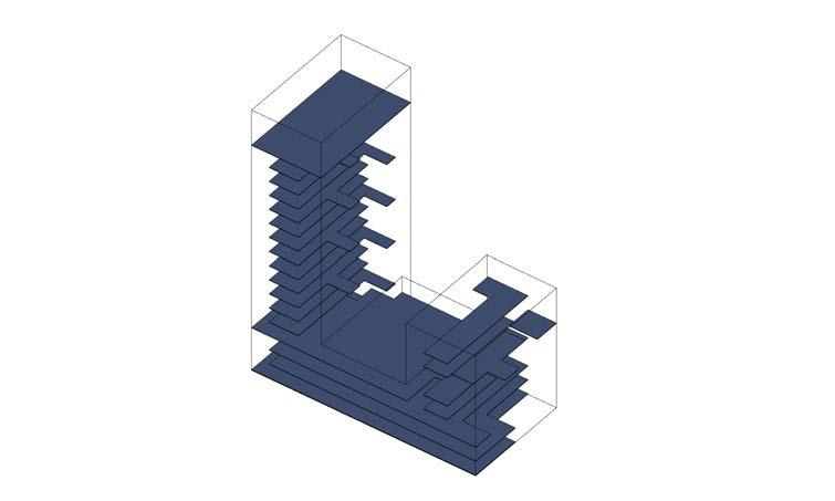
On this account, the proposed design consists of three different volumes. To appropriately respect DTU‘s heritage and history, B and C match the hights of existing neighbor buildings. Thereby a strongvisual connection to the surroundings is drawn.

Furthermore, the design was significantly shaped by the fact that it must function as an architectural landmark (see site analysis). This is why the third volume A is designed as a 70m tall tower that sets a grand contrast to all circumjacent buildings. The tower is located in the north, to make sure it does not overshadow the remaining property.
A modern landmark is established that respects its built environment and constitutes a visonary and inspiring work environment.


The design proposes a public, green roof terrace that can be accessed from Building A and C. It is directly connected to the cafeteria and can be used for outdoor dining. A sunlight simulation was performed in AutoCAD Revit to examine the shadowing of Building C over B. During noon some areas are shaded. This however has the advantage, that overheating is minimized in B (despite it having an atrium with a glass roof). Furthermore, the shade can actually provide a welcome coolness, especially in the summer months.
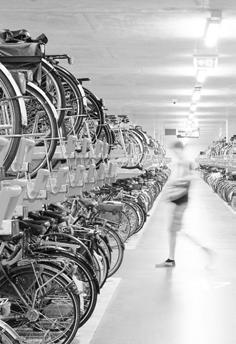
A large and modern bike parking area is located in the underground floor aiming to encourage building guests to use sustainable mobility modes (as aspired by the Strategic Campus Plan). The entrance is located at the mobility hub (see site analysis).

Three Standalone Structures
The static system is made up of two cast-in place structural cores (which meet most of the load-bearing demands in each respective building), prefabricated reinforced concrete columns, beams and floor slabs.


The columns have a square dimension of 0,5m x 0,5m. The further the building develops upwards, the more their diameter is optimized and decreased. This allows to save material and maximize space efficiency.
As requested by both fire and structural engineers each building section (A, B and C) is designed as a standalone structure to increase robustness and fire safety.

A grid of 4,5m functions as a formgiving and organising pattern throughout the design. The layout of all interior spaces as well as the facade rhythm is based upon it.

Housing the Main Building Funtions
Core A and C form the structural and functional heart of the building. Volume B is low enough (12m high), that it doesn‘t require a core for structural support. All its rooms can be accessed either directly from the ground level or via connecting walkways between A and C.

The optimization of the cores, both in terms of function and space efficiency, was an integral part of the planning phase and a highly interdisciplinary process in which all subjects collaborated:
The outer walls of the core are loadbearing (STRU). Each core has both a pressurized staircase, a fire and escape elevator (FIRE). Other fire safety requirements include a lobby in front of the staircase (> 5m2) and 1,2m wide doors that open in the direction of the escape route. The toilets are also located in the cores, including four disabled toilets (in line with the Danish Building Regulations §223). The main MEP shaft lies at the top-end of both cores. The load-bearing structure closes already behind the toilets. Thereby wall openings for pipes in the „top-end“ wall do not impact the core‘s load-bearing capacity (see also grid top view to the left). Since it was unclear in the beginning, how large the MEP shaft must be (and the corresponding calculations would take several weeks), the shaft was layouted in a way that its size could increase flexibly (upwards). The space behind the core functions as community space and can tolerate possible shaft enlargements (see also floor plans in appendix). Since building C is only 30m high and houses fewer occupants than A, the core was optimized in size to increase space efficiency. To simplify planning, it is nevertheless designed with the same principles and only its depth is decreased.
3) DGNB supports buildings that encourage sustainable mobility modes. The proposed focus on bicycles is highly credited and in line with the DTU Strategic Campus Plan.
The first room visitors enter after passing through the main entrance is a large two-story foyer. Generous daylight falls through the glazed facade as well as the atrium in the middle of volume
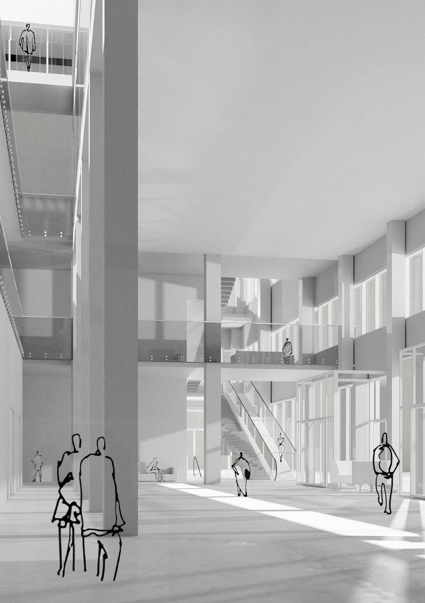
B. Open views to the second and third floor allow the visitor to immediately get a feeling for orientation, spaces and life in the building. All large meeting rooms and auditoriums are located directly next to or above the foyer.
A wide staircase with escalator connects the ground floor not only practically, but also visually directly to the higher floors. This special feature invites visitors to linger, explore and see the building from different persepectives.



Part of the building design is a basement floor, which is on the same level as the courtyard. The courtyard is accessible both from the main access road in the south via a spacious staircase as well as directly from the auditorium °3. Furthermore, the basement houses large MEP areas °2. Their size has been optimized in consultation with the MEP team.
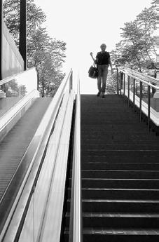
The main function of the underground floor is to house bike parking areas °1. Over 500 bikes can be stored in duplex bike parking systems. The bike access is arranged with two walkway escalators in the south western part of the building. Between the escalators there is a 2,2m wide staircase for pedestrians. This furthermore functions as one of the emergency fire exit routes.


The main entrance is located at the west side towards Fysikvej. A light and spacious 8m-high grand foyer welcomes the visitor. The reception provides information °4. Behind it lies the largest room of the building: an auditorium for 200 people °3. Positioning it on the ground floor was a very conscious decision to enable easy orientation for attendees. Furthermore it maximizes efficiency and safety.
On the ground floor, each core has a seperate emergency route (shortest way) - a fire safety requirement. Building A houses a public cafe °4 as well as delivery, waste disposal and mail room °6. Furthermore, the cafeteria can be supplied directly with food deliveries via two extra lifts, which connect the 1st and 4th floor. In the South, there is a small office °5, a workshop room and the entrance to the bike parking °1.


The foyer is the beginning of an atrium °7 that extends up through building B to the roof terrace (4th floor). It allows generous daylighting despite the building‘s depthness on the lower floors. The atrium furthermore establishes visual connections between floors and functions. Someone standing in the foyer and looking upwards can observe students leaving the small auditorium (100 people) or watch the clouds go by through the elongated glass roof.
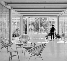
The second floor houses office spaces °5 in A and C. The two building volumes are connected via a walkway from which one can look down to the foyer and entrance. A meeting room for 40 people is located in B °8. Several break-out areas in front of and next to the business rooms create comfortable spaces for more casual conversations, waiting and relaxing °9.




In addition to various meeting rooms in the office spaces, there are four big meeting rooms °8 that provide space for up to 40 people. In combination with the auditoria °3, they are all located in B (the heart of the building). Layouting them on top of and next to each other enables optimal orientation and ventilation supply (MEP). Each meeting room is equipped with a small foyer and break-out spaces. The 3rd floor can be accessed either via the cores or the grand staircase in C and the connecting walkway, which lies right under the atrium glass roof.


In general, auditoriums are built with a slope to improve the vision for listeners. In the front row the open height is 7.6m. Wheelchair users can sit in the back row, close to the entrance of each auditorium.

Other than that, the third floor houses offices spaces (A, C) and common leisure areas.


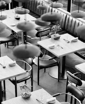
The building has its own cafeteria, located on the fourth floor. It provides around 130 seats plus additional 100 on the roof-top terrace (Building B). The kitchen is equipped with a large cooking area, one staff and two storage rooms. Specific food supply elevators connect the kitchen to the delivery room on the ground floor. Seperate counters allow to distingusih between offers (e.g. northern counter = vegetarian) and distribute the guests.
The cafeteria is divided into three different areas, seperated with glass walls to optimize the acoustics.
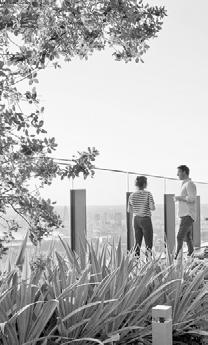
The roof terrace can be accessed from building C as well as from the cafeteria. The garden offers green spaces, various furniture for socializing and having lunch. It is the perfect spot to enjoy a break, watch the sunset or peer through the atrium from above down into the foyer.


The 17th floor rises 65m above the ground. It is the tallest building in the entire area. From up here, one can enjoy breathtaking 360° views over DTU campus, the surroundings, all the way to Copenhagen. Here, the clear floor hight is 4.2m, creating a high-class and generous space.
A skybar °12 offers refreshments and seating. A storage room for beverages and supplies is located right behind the bar counter. Several steps are added on the western side of the core. They offer the opportunity to hold small presentations or workshops, but can also be used as observatory °14. A larger event area is located on the north side °13. Its use is flexible. It can for example function as an exhibition space, be used for private parties or as an additional business room for conferences and meetings.
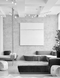
reference pictures of buildings with similar features: auditorium | break-out area | roof terrace | skybar and observatory
The main use of the building is to provide office space. Therefore eleven floors are planned exclusively for office use (63% of the net floor area). Each floor can provide a maximum of either 102 open plan work stations or 48 single offices.


The frame construction allows for a high flexibility in the office layout. Walls and spaces can be easily adapted to the tenants wishes (see mixed office example).


The staircase and toilets are located within the core. This was a very concious layout decision by the architects, as it allows for each floor to be divided into two independent office areas. If so, each company has their own entrance from the core. Overall, there can be up to four independent offices per floor.
The office layout is divided into individual work spaces, meeting rooms („The Team“) and community spaces.
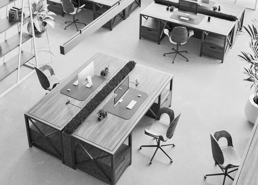


Each workstation has a shelv. The desks are adjustable in hight. There are at least three meeting rooms (10, 12 or 24 people) on each floor - usually combined with an additional workshop room or small seperated lounge. The community areas are essential to each layout. The exchange between employees not only increases satisfaction but also the efficiency and success rate of each business. It is therefore crucial to encourage social exchange. Various break-out areas offer respective opportunities. Another element are kitchenettes for coffee and/or lunch preparation (located at the MEP shaft to allow optimization of pipes). Community areas are located next to the facade. Employees can thus enjoy the view and scenery while taking a break.
Starting in the first week of the design phase, architects worked together closely with building climatologists (MEP).

In order to optimize daylight use for workplaces, desks must not be more than 7m from the window: „There should be 300lux in at least half of the area with permanent workspaces at least 50% of the hours with daylight.“ (Danish Building Regulation) This is another main reason why the design team decided to not increase the hight of building B and instead maximize the facade area of A and C. Furthermore, offices located in the north should be even less deep, since daylight is scarce. This is why the building core is shifted up (and not in the middle).
Due to all the factors considered, the design proposal offers excellent daylight conditions, creating high-quality workspaces for everyone.


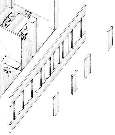

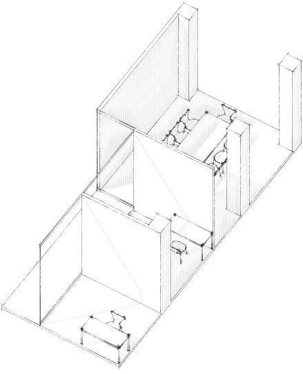
The facade development accounts to probably the most interdisciplinary process within this project. While ARCH was leading the design decisions, they were majorly influenced by the requirements of all other subjects. The concept was developed and optimised step by step over a period of two months through intense collaboration to create both a highly functional and aesthetically pleasing facade.
°1 DESIGN CONTEXT AND RESEARCH

An in-depth research of reference projects was performed and the site‘s surrounding facades were analyzed (see pictures below).
°2 INDEPENDENT STRUCTURE

The facade envelopes the building thermally and visually but has no load-bearing function (curtain wall). Changes in the facade (e.g. its dead weight) were closely discussed with STRU throughout the design process and included in the load-bearing calculations accordingly.
°3
From an architectural perspective large windows are desirable to enhance interior quality through views and daylight. At the same time, MEP argued for a more closed facade to avoid overheating.


The essential question was therefore: Where would a glazing reduction make most sense?









Daylight in office spaces is only taken into account above 85cm (according to the Danish Building Regulations). Glass areas below only contribute to overheating. For this reason it was decided to place windows 85cm above floor level. Furthermore, the facade was closed just down to below the suspended ceiling. The remaining area allows the installation of still generous 1.85m high windows. The design corresponds with the general DTU surrounding since most facades at the campus emphazise horizontal lines (e.g. building 309, see below).
Despite the measures taken, simulations in IDA ICE and Rhino showed that the issue of overheating was not completely solved. The MEP team thus called to close another 25% of the facade. To not loose additional window hight/ quality, the architectural team decided to remove window space in front of columns - since view and daylight are limited here anyway.
°4
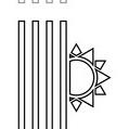
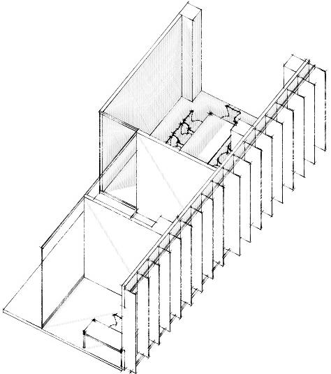
However, emphazising verticality in the facade was also important to the design team to reflect its function as a 70m-high landmark. This goal was implemented by adding vertical fins that emerge from the facade, climb up the building, stress its hight and furthermore function as sun shading elements.
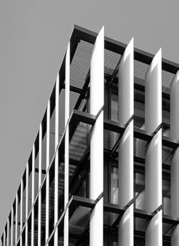


The fins can be installed both moveable and fixed. Particular (dis-)advantages were discussed in detail with the whole team. Moveable elements allow a high degree of user flexibility, but imply high construction and maintenance costs (PM). It is also unclear who is allowed to control them (Everyone? Or only some? Opens new discussion) and poses many simulation issues in regards to overheating and wind loads (MEP, STRU).
°6 FIN SPACING AND DEPTH


To determine the influence of fin spacing/ depth on daylight/ overheating a sunlight analysis was carried out in Rhino and Grasshopper. Based on the results, it was decided to place fins 60cm apart from each other. Their depth varies (compare reference EDP Headquaters below). Since daylight requirements depend on the use of space, each fin depth was individually optimized in a detailed cooperation process (see MEP subject report for details).
°7
In short, different solutions were combined to reach an optimal compromise. The ground floor facade is transparent without fins. In rooms where complete darkening of the space makes sense (e.g. the auditorium), the decision was made for moveable fins. In other spaces (e.g. open office) fins are fixed. The result is a highly functional, material and cost efficient facade, that creates an intriguing playful dynamic and versatile rhythm
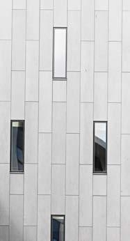
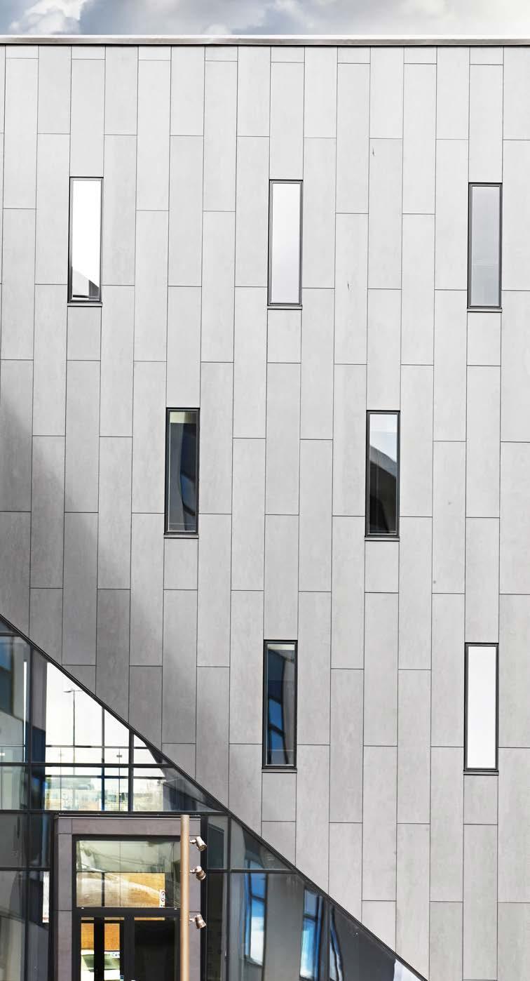
It was agreed to break with traditional materials such as brick, concrete and wood - both for sustainability as well as fire reasons. For the horizontal facade stripes cembrit pannels are proposed. Cembrit is a sustainable and multi-use materialit can even be utilized for interior finishings such as partition walls or ceilings, thereby increasing the building‘s cost efficiency. The color suggestion is white to set a contrast to the dark building 310 and obtain a light and more gentle aesthetic. The facade is non-combustible with a fire class of A2-s1, d0, meaning it will not spread a potential fire vertically. Furthermore, cembrit is maintenance, crack and mold free, durable and ensured by a 15 year warranty from the producer. To convey an open and welcoming impression the other rest of the facade is made of 3 layer energy glass.
Structural elements and MEP piping is covered by a suspended ceiling to continue the „tidy“ and elegant style of the design and save installation costs (PM). A Dampa climate ceiling is proposed (local Danish production) since it has an integrated cooling and warming function. It is commonly used in office buildings, hospitals, large kitchens, canteens, educational institutes and other administrative buildings. Its flexible adjustment allows to achieve optimal interior climate conditions.
The final floor-to-ceiling hight is another result of the multi-layer interdisciplinary design process. As already shown, the design of the facade underwent several phases (previous page). The same applies to the interior space directly behind it. For example, night-cooling windows were planned originally. They were later discarded after it became clear by MEP‘s calculations, that exclusive cooling via interior ventilation is both more efficient and cost-effective. As a result, the window division was dissolved and combined into one large window (185mm high, see left).
If one looks closely at the facade detail, one will notice that the ground floor °1 and 17th floor °17 differ in design. This was a concious decision made in consultation with MEP and PM. To meet the requirements of the DTU Strategic Campus Plan and Lokalplan the ground level is entirely glazed, thereby creating a welcoming expression.
On the 17th floor, the lower cembrit facade stripe is reduced to maximise views from the skybbar. This optimisation was possible, because there is no office space and other MEP requirements apply.
An additional adjustment that took place just last week was the floor to ceiling height. Again, MEP had originally planned for a 920mm suspended ceiling. Calculations showed that the hight could however be reduced to 420mm by thought-through and smart pipe allocation. Accodingly, the floor to ceiling hight is increased to 3.2m in office spaces, which positively impacts the architectural spatial experience.
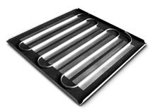
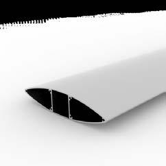
Sunshading elements by the manufacturer Colt SolarFin (see datasheet in appendix) stress the buildings verticality. They are clamped to a steel mount, which is attached to the slab. The fins are made of white aluminium and are either 60cm or 40cm deep depending on the roomhight (example to the left: meeting room with 60cm fins).


Further details on the proposed interior materiality are indicated on the following page.

Every building is a material depot. Next to energy optimisation and flexibility of use, material choices are an essential component of every sustainable building. The design team has decided to aim for a circular approach, taking into account the recyclability of each material. Can it be reused at the end of the building‘s lifecycle? Does it have a material passport? (Thomas Rau) etc.
Materials not only determine how long a building lasts, but directly impact the happiness of its users. Do they enjoy their workspace surrounding? How does it impact their wellbeing and comfort? Materials co-determine the quality of every building.
The design proposal suggest a warm color palette that consists of natural tones, continuing the elegant expression of the facade in the interior.
Product certification acts as an idicator of a product‘s safety, reliability and quality. All products proposed for the interior design have been certified. A particular focus lies on C2C certification, since it specialises in individual products (unlike DGNB which considers the building as a whole). The C2C standard is one of the highest in the world accessing material health, reuse, renewable energy, carbon management, water stewardship and social fairness.
The proposed Interface carpets have for instance achieved a gold C2C certificate and the office chair is 100% recycable (see more details below and in appendix). Repair by Steelcase is free. This points to another concept we would like to emphazise: Product as a Service (PaaS) = products are offered as subscription models creating a circular product lifecycle. Lately, more and more manufactures have started to climb the sustainability ladder and it is now already possible to subscribe to carpets or light (e.g. Philipps Light as a Service).
In the long-term the PaaS model saves costs due to optimised systems and higher product quality.
building envelope
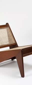
Depending on each space use, we propose different materials in the building. In the public ground floor with foyer and cafe a beige stone floor is laid °2 and °6. Auditoriums, cafeteria and skybar have wooden lamella wall claddings with accoustic panels °4. Office areas are carpeted (accoustic reasons). Different carpet colors stress the different use of space (e.g. light grey °9 = community area, dark grey °10 = meeting room). Workplaces are furnished with Steelcase Office Chairs °11, break out areas with lounge chairs by Srelle °12.
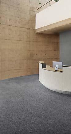
This range of products and materials is intended to represent a starting point for discussion. In theory, it would be further developed during the upcoming design stages in consultation and with consideration of the client‘s wishes.
°1 facade panel, cembrit patina original P222
wall cladding
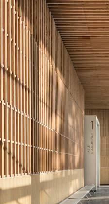
°2 exposed concrete, Marazzi Plaza Collection
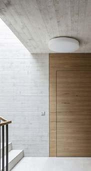
°3 white plaster


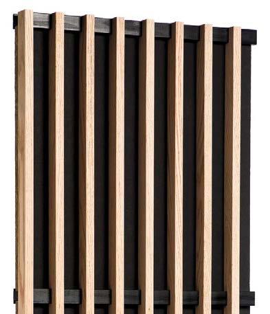
°4 wood lamellas, Laudescher Linea 2.4.5

floors
°5 stone tiles, Marazzi Plaza Collection naturale M9AU


°6 stone tiles, Marazzi Plaza Collection beige M95C
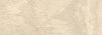

°7 wood parquett, Tarquett Desso, oak nature VIVA

°8 carpet, interface conscient range, 4195004 Refined

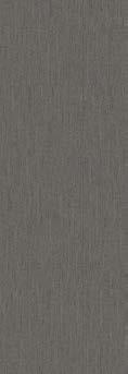
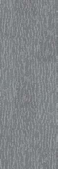

°9 carpet, interface conscient range, 4195001 Factor
°10 carpet, interface conscient range, 4195002 Factor
interior design and furniture

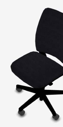
°11 office chair, Steelcase Amia

°12 Srelle office and lounge chair for foyer and break-out spaces
°4 wood lamellas, accoustic pannels, Laudescher Linea 2.4.5
°13 Beddeleem JB Pure 100 double glazed partition walls

Through a holistic approach a visonary landmark is created that respects its heritage and surroundings.



Design and layout encourage social exchange and promote public areas - creating a building for everyone.




Flexible space planning, energy efficiency, circular materials, healthy interior environments, optimized use of natural daylight and a focus on bike mobility establish a showcase sustainability project.


4







By focusing on constantly close cooperation between all subjects, highly optimised, efficient and appealing design solutions are achieved.





11080 ADVANCED BUILDING DESIGN
SPRING 2021 | TEAM 01

Advanced Building Design (11080)
Date: 3 week
Drawn by: ARCH | Group 1 Scale 1:1.000


A


B C


Elevator Technical Specification
Your Configuration ID: C-143765
GENERAL INFORMATION
Product Name KONE MonoSpace® 700 DX

Main Regulation EN81-20
Complementary Regulation EN81-72 (Fire fighting)
Group size 1 Elevator
Speed 2.5 m/s
Load 1000 kg / 13 persons
Total travel 100000 mm
Landings 27
Number of entrances 27
MACHINE ROOM
Machine location Inside shaft
SHAFT SPECIFICATION
Shaft size 1650 mm x 2485 mm
Min. Req. Headroom Height 4400 mm
Pit Depth 1950 mm
ELEVATOR LANDINGS
Door Type Side Opening
Door Width 900 mm
Door Height 2000 mm
Entrance Type Frame
Maintenance Access Panel (MAP) TypeMounted on Door Frame
CAR
Car type Single entry
Car Size (w x d) 1100 mm x 2100 mm
Car Height 2200 mm
CAR DECORATION
Ceiling CL82 Murano Mirror (H) mirror polished stainless steel
Right wall (B) Trusted Blue (SMART) (L244) smart surface laminate
Back wall (C) Spring Yellow (GP3) painted glass
Left wall (D) Trusted Blue (SMART) (L244) smart surface laminate
Floor Quarz Gray (RC31) Rubber flooring
Car Operating Panel KSC D23 Carbon Black
Handrail HR64 Carbon Black (P70) powder painted stainless steel
Skirting (SK1) Carbon Black (AFP) (CB) brushed anti-fingerprint stainless steel
Please note that the Planner tool and outputs are for preliminary design purposes and not for construction. Before committing to any construction decisions, please contact your local KONE representative to verify the configuration.
Advanced Building Design (11080)
Date: 3 week
ARCH | Group 1
PROCESS QUALITY
Cembrit provides detailed guidance for design, handling and installation of products, to ensure a perfect installation and to minimize risk of installers leaving defects in the construction.
Cembrit provides full documentation of required building data and the composition of the materials, as well as on the environmental impact. Our products are tested on the quality of execution to the harmonised standards, datasheets and safety datasheets.
ENVIRONMENTAL QUALITY
Cembrit build & indoor boards do not contain hazardous substance and are living op to the current REACH policies. All cement and mineral fillers are extracted locally and delivered directly to Cembrit factories, to minimise the transportation of raw materials. Most finished goods are transported by train or by sea to lower CO2 emission during transportation.
Wastewater treatment plan ensures water discharged to the public sewerage system contains no harmful particles or residues from production. Dust and wet cuts are recycled back into the production.The cellulose in Cembrit facade boards is FCS-certified wood fibres from either pine or spruce.
ECONOMIC QUALITY
Cembrit build and indoor products are guaranteed to meet industry requirements for cost-effective construction as well as long-term durability. The long expected lifetime of our products not only ensure a robust product, it also affects the financial robustness of the building in the building’s total Life Cycle Costs (LCC).
Our boards require none or very little maintenance, and there are no costs associated with operation and maintenance of the building. If a board must be removed e.g. because of damage, our facade boards can be removed in a non-destructive way simply by removing the mounting screws and install a new sheet.
Cembrit fibre cement products are designed to last for decades.

At Cembrit, we strive to utilise resources efficiently, reduce waste and emissions on the environment.
Cembrit build and indoor boards have an expected lifetime of 40-60 years.
CEMBRIT - SUSTAINABILITY
Advanced Building Design (11080)
Date: 3 week
ARCH | Group 1
A.15
Let ydervæg med beklædning af Cembrit Facadeplader fibercement Tung ydervæg med beklædning af Cembrit Facadeplader fibercement
Cembrit Patina Inline
Cembrit Patina Inline fås i fire dimensioner: 1192 x 2500/3050 mm
De for Cembrit Patina Inline særlige montagedetaljer (som afviger fra montagemetoden til øvrige Cembrit Patinaprodukter), beskrives nedenstående.

Cembrit Patina Inline forbores med et Ø8 mm-bor, der er velegnet til fibercement.
Kantafstand skrueplacering Skruens placering forhold til pladekanter, afhænger af, hvordan pladen placeres på understøtningen (vandret eller lodret).
understøtningens længderetning, placeres skruen 70 mm (maks 150 mm). fra pladekant.
Vinkelret på understøtningen, placeres skruen 30 mm (maks. 100 mm) fra pladekant. (fig. 3.) Skruerne placeres altid centreret på en toplinje (fig. 1). Skruer må aldrig placeres bunden af et spor.
Cembrit beklædning Den yderste facadebeklædning, skal forhindre udefra kommende fugt at trænge ind konstruktionen
2 Underlag, EPDM bånd Som direkte underlag for pladerne benyttes EPDM bånd.
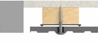
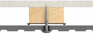

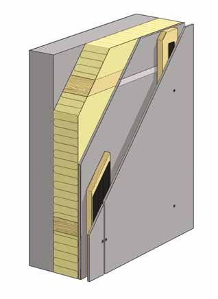
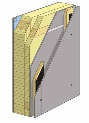

3 Understøtning afstandslister eller lægter
forhindre vinden i at blæse igennem væggen samt evt. give brandbeskyttelse.
Cembrit Windstopper 9 mm tykkelse er godkendt som K1 10 B-sl, d0 (klasse1) beklædning.
6 Cembrit 12-h-skinne til Cembrit Windstopper

7 Isolering
Det samme gør sig gældende for skruer monteret midt på pladen – her sikres det, at understøtningerne er placeret sådan, at skruerne altid kan placeres i en toplinje.
Kantafstande på tildannede plader Hvis pladen tilskæres i forbindelse med facadegennembrydninger, eksempelvis døre- og vindueshuller, vil det ikke altid være muligt at placere skruen præcist 30 mm fra kant og samtidig en top linje –her rykkes skruen til den næste toplinje, så de 30 mm som minimumsafstand til pladekant overholdes (figur 4).
Af hensyn til forankringsdybde anvendes 22 mm høvlede understøtninger ved brug af Cembrit Facadeskruer og 34 mm ved brug af Cembrit Facadesøm.
Cembrit Montageprofiler1) Cembrit Profil 100 til pladesamlinger. Cembrit Profil 70 til mellemunderstøtninger. Cembrit Profil 40 til start og slut.
4 Ventileret hulrum Det ventilerede hulrum bag Cembrit facadebeklædningen skal udligne de trykvariationer, der fremkaldes af vindstød, samt bortventilere såvel udefra som indefra kommende fugt.
5 Vindspærre Konstruktionens vindtætte lag af Cembrit Windstopper plader skal
1) Kun 8 mm plader kan anvendes til stålunderstøtning.
Varmeisolering udføres normalt med mineraluld. Ved store isoleringstykkelser kan isoleringen udføres 2 lag. Fastholdt isolering skal udfylde hulrummet helt.
8 Træskelet
9 Dampspærre På konstruktionens indvendige side opsættes dampspærre, før den indvendige beklædning monteres.
10 Indvendig beklædning Indvendig beklædning med Cembrit Multi Force.
11 Bærende ydervæg
Advanced Building Design (11080)
Date: 3 week
ARCH | Group 1
Colt Solarfin is a fixed or continuously variable louvre-system that can be installed in front of façade glazing and on glass roof constructions. The system reduces any direct solar incoming radiation in the summer and by that, it prevents an undesired warming up of the inside rooms by solar radiation. On the other hand, during the winter the louvres can be completely open, providing optimal sunlight ingress for passive solar energy.
This results in enormous savings on installation and exploitation costs. During warm periods, the necessary cooling expenses in air-conditioned buildings are strongly reduced and, in cold periods, less heating is needed due to the maximal use of passive solar energy.
Solarfin is a system with multiple applications in commercial and industrial buildings.


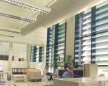

Design
The Colt Solarfin system is available with fixed, movable, horizontally or vertically installed aluminium louvres that can be adjusted to any desired position. The extruded lenticular louvres are available in many different dimensions. The substructure and the supporting profiles provide a wind- and weatherresistant system.

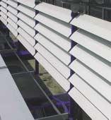

Colour
Standardly, the Solarfin system is manufactured in plain aluminium. In order to intensify light-and heat-reflection or just to meet the most various architectural requirements, the system can yet be coated in blank anodised or in any other desired RALcolour.


Electronic control
With the CCS 2000 control system, the position of the louvres is automatically adjusted by means of spindle motors.
This tuning depends on the time of the day, the date, the orientation of the façades or the glass roof construction, the inclination angle of the glazing, the sun azimuth and the light intensity.

Furthermore, the louvres can be placed in a desired position by means of a switch, for the purpose of cleaning or service activities, or by external signals of a weather station. The modular construction of the CCS 2000 system offers different possibilities, which may vary from a completely autonomous system until integrated control versions.
Advanced Building Design (11080)
Date: 3 week
ARCH | Group 1
EN
CQuest™Bio is non-vinyl, non-bitumen made with a bio-composite, containing bio-based and recycled fillers. These materials, when measured on a standalone basis are net carbon negative.
DE
CQuest™Bio ist eine PVC- und bitumenfreie Rückenkonstruktion, in der biobasierte und recycelte Füllstoffe verwendet werden. Einige der darin enthaltenen Materialien sind für sich betrachtet netto CO2-negativ und reduzieren unseren CO2-Fußabdruck maßgeblich.
FR
CQuest™Bio est notre nouvelle sous-couche pour dalles de moquette, sans PVC et sans bitume. Elle est fabriquée avec un bio-composite, mélange de matériaux biosourcés et recyclés au bilan carbone net négatif.
NL
CQuest™Bio is onze nieuwe vinylvrije, niet-bitumen tapijttegelbacking gemaakt van een bio-composiet met biobased en gerecyclede vulstoffen. Deze materialen, gemeten op een stand-alone basis, zijn netto CO2-negatief.
ES
Sustainability - Conscient EN

CQuest™Bio no contiene vinilo ni bitumen. Está fabricado con compuestos bio y rellenos orgánicos y reciclados. Estos materiales son negativos en emisiones de carbono.
SE
www.interface.com/cquest
Standard Backing CQuest™Bio
CQuest™Bio är vår nya baksida för textilplattor. Den innehåller varken vinyl eller bitumen utan är tillverkad av biokomposit som innehåller biobaserade och återvunna fyllnadsmaterial. Detta gör CQuest™Bio netto koldioxidnegativ.
Backing
CQuest™Bio is non-vinyl, non-bitumen made with a bio-composite, containing bio-based and recycled fillers. These materials, when measured on a standalone basis are net carbon negative.
DE
CQuest™Bio ist eine PVC- und bitumenfreie Rückenkonstruktion, in der biobasierte und recycelte Füllstoffe verwendet werden. Einige der darin enthaltenen Materialien sind für sich betrachtet netto CO2-negativ und reduzieren unseren CO2-Fußabdruck maßgeblich.
FR
CQuest™Bio est notre nouvelle sous-couche pour dalles de moquette, sans PVC et sans bitume. Elle est fabriquée avec un bio-composite, mélange de matériaux biosourcés et recyclés au bilan carbone net négatif.

CQuest™Bio is onze nieuwe vinylvrije, niet-bitumen
tapijttegelbacking gemaakt van een bio-composiet met
Carbon Neutral Floors™
ReEntry®
EN
EN
When you specify flooring from Interface, you’re selecting products that are carbon neutral across their full product lifecycle.
DE
Wenn Sie sich für Bodenbeläge von Interface entscheiden, wählen Sie Produkte, die über ihren gesamten Lebenszyklus CO2-neutral sind.
FR
Lorsque vous choisissez un revêtement de sol Interface, vous optez pour des produits neutres en carbone, tout au long de leur cycle de vie.
NL
Interface promises to take back our customers used flooring product (carpet tile, LVT and Rubber) and create further value with them in the most sustainable way.
DE
Wir geben Ihnen das Versprechen, Ihre gebrauchten Interface-Bodenbeläge zurückzunehmen und damit einen Mehrwert auf nachhaltigste Art und Weise zu schaffen.
FR
Interface accompagne ses clients dans la reprise de ses revêtements de sol usagés, afin de leur donner une deuxième vie de la façon la plus éco-responsable possible.
NL
Wanneer u vloeren van Interface specificeert, selecteert u producten die klimaatneutraal zijn over hun volledige product levenscyclus.
ES
Interface belooft onze gebruikte vloerproducten van klanten terug te nemen en creëert daarmee meerwaarde in de meest duurzame manier.
ES

Installation method Floating or glue down
instruction Download from www.tarkett.com Contact your supplier for more details
Underfloor heating compatible Maximum floor surface temperature 27oC with self-regulating under-floor heat system

Start & Stop: Shorter lengths of planks included in approx. 1 pack per 20 m2
RECOMMENDED ACCESSORIES
Installation Tarkofoam II / Tarkoflex II Installation kit
Aesthetics Skirting Transition moulding Pipe covers
& Maintenance Wood Floor Care Kit / Spray Mop Kit
See more alternatives and the complete range of accessories @ www.tarkett.com
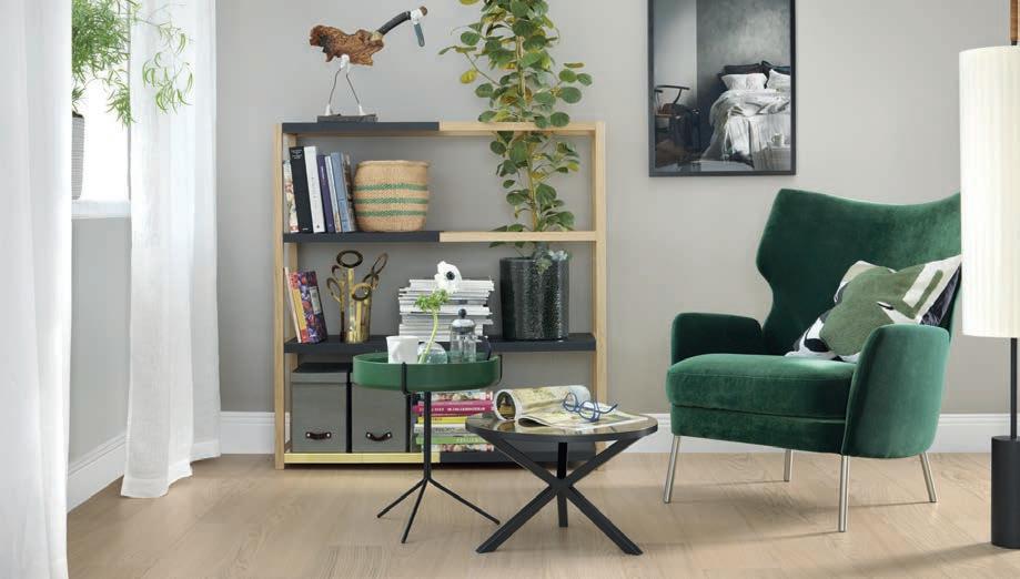
These Tarkett wooden floors have a Proteco surface treatment and therefore a strong protection against normal wear, abrasion, scratches and stains. Some floors will require more frequent maintenance for increased life span. Generally these products are light coloured floors and hardwax oiled floors, particularly with brushed surface and/or highlighted details, such as saw marks. Please always refer to maintenance guidance available on websites.
See maintenance instructions @ www.tarkett.com
Advanced Building Design (11080)
Date: 3 week
ARCH | Group 1
/ B-s1,d0 / B-s2,d0
Acoustic absorption was measured as per the ISO 354 standard. The various data relating to acoustic absorption αp, αw, absorption class) have been calculated according to ISO 11654 standard (LINEA + acoustic supplement).



lifecycle performance environmental overview
Environmental Overview
Final Assembly Location
Life Cycle Performance
Steelcase considers each phase of the life cycle: from materials extraction, production, transport, use and reuse, through the end of its life.
Materials
This phase includes raw materials extraction and transformation into material ready to be used.
Amia contains 26% recycled materials by weight (15% postconsumer + 11% pre-consumer).
Steelcase considers each phase of the life cycle: from materials extraction, production, transport, use and reuse, through the end of its life.
Materials chemistry assessment completed for this product.
Low formaldehyde and VOC emissions when Amia tested in accordance with ANSI/BIFMA M7.1 following the criteria detailed in ANSI/BIFMA e3 Sustainability Standard, Low Emitting Furniture credit 7.6.
• Amia may meet the Healthier Interiors goal of Healthier Hospitals, depending on options. Please visit the Healthier Hospitals website for a complete list of Steelcase products that may contribute to the Safer Chemicals Challenge.
Amia may meet the Red List Imperative requirements of the Living Building Challenge Materials Petal, depending on options.
LICENSEDMARKS:
Materials
Materials Composition
A break down of the basic materials in Amia.
Materials Chemistry
Steelcase’s materials chemistry practice aims to design products with materials that support human and environmental health, throughout all phases of the life cycle.
Recycled Materials and Recyclability
Amia contains 26% recycled materials by weight (15% post-consumer + 11% pre-consumer).
At the end of its useful life, Amia is 89% recyclable by weight.*
CradletoCradleCertified™
Steelcase,Inc. FORTHEBELOWLISTEDCERTIFIEDPRODUCTSASSOCIATEDWITHTHENAME: Amia™ChairandStool CradletoCradleProductsInnovationInstitute
Certifications and Labels
The environmental and social performance of Amia is communicated through the following voluntary labels/certifications:
Environmental Product Declaration (EPD)
• BIFMA level® 3
SCS Indoor Advantage™ Gold
• Cradle to Cradle Certified™ textiles available

LEED Contribution
Amia may contribute in the following areas:
Recycled content
• Materials reuse
• Regional materials
Rapidly renewable materials
• Low-emitting materials
• Interiors life-cycle impact reduction
Building product disclosure and optimizationenvironmental product declarations
• Building product disclosure and optimization - material ingredients
Daylight and views
• Building product disclosure and optimizationsourcing of raw materials
Quality Views
• Construction & Demolition Waste Planning & Management
• Certified Multi-attribute Products and Materials
Social equity within the supply chain
*In locations where recycling is available. Steelcase offers services to assist customers with end-of-use options including resale, refurbishment, charitable donation, and recycling.
Cradle to Cradle Certified™ textiles available to specify with product. (Amia Air only)
Product comes standard without PVC.
Production
• Amia may meet the Toxic Material Reduction Optimization Feature of the WELL Building Standard depending on options.
This phase comprises all production and assembly processes taking place at Steelcase or at their suppliers and sub-suppliers.
The plant in Reynosa, Mexico is ISO 14001 certified. Water-based adhesives used in assembly.
• Final assembly of Amia is in Reynosa, Mexico by Steelcase for the Americas Market.
Use
• Bulk packaging used for this product, wherever possible, to optimize volume in shipping. Made in North America
During the use phase of the product - the longest phase of the life cycle - no significant environmental impacts occur.
Product meets ANSI/BIFMA Standards M7.1/X7.1 for low- VOC emissions to indoor air quality - SCS Indoor
Advantage™ Gold.
Designed for a long product life with replaceable parts that are easy to change.
End of Use
• Cleaning instructions available. Maintenance information available upon request.
Any product can become a resource itself, or be responsibly disposed of in different ways.
Designed to enable responsible end of use strategiesre-selling, refurbishing, charitable donation or recycling. 89% of the materials by weight can be recycled, according to the current waste disposal schemes.
• Primary plastic parts clearly labelled for easy sorting and effective recycling, according to ISO 11469. Disassembly and recycling directions available upon request, for a representative configuration.
2
For more information
Ask for the Environmental Product Declaration (EPD) (according to ISO 14025) which communicates the estimated environmental impacts of this product throughout its life cycle, using the life cycle assessment methodology ISO 14040/14044.
3
Advanced Building Design (11080)
Date: 3 week