Parker P1D Series Actuators

Page 1

aerospace climate control electromechanical filtration fluid & gas handling hydraulics pneumatics process control sealing & shielding

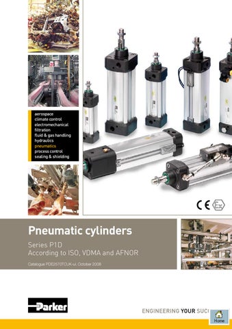
Pneumatic cylinders Series P1D According to ISO, VDMA and AFNOR Catalogue PDE2570TCUK-ul. October 2008


P1D

Cylinder Features Air Hydraulic cylinder cylinder

Electro mechanical actuators

Overload safe

***

***

*

Easy to limit force

***

***

*

Easy to vary speed

***

***

*

Speed

***

**

**

Reliability

***

***

***

Robustness

***

***

*

Installation cost

***

*

**

Ease of service

***

**

*

Safety in damp environments

***

***

*

Safety in explosive atmospheres

***

***

*

Safety risk with electrical installations

***

***

*

Risk of oil leak

***

*

***

Clean, hygienic

***

**

*

Standardised measurements

***

***

*

Service life

***

***

*

Hydraulic system required

***

*

***

Weight

**

**

**

Purchase price

***

**

*

Power density

**

***

*

Noise level during operation

**

***

**

High force for size

**

***

*

Positioning possibilities

*

***

***

Total energy consumption

*

**

***

Service interval

*

**

***

Compressor capacity required

*

***

***

* = good, **=average, ***=excellent

Important

Note

Before attempting any external or internal work on the cylinder or any connected components, make sure the cylinder is vented and dis­connect the air supply in order to ensure isolation of the air supply.

All technical data in this catalogue are typical data only. Air quality is essential for maximum cylinder service life (see ISO 8573).

WARNING FAILURE OR IMPROPER SELECTION OR IMPROPER USE OF THE PRODUCTS AND/OR SYSTEMS DESCRIBED HEREIN OR RELATED ITEMS CAN CAUSE DEATH, PERSONAL INJURY AND PROPERTY DAMAGE. This document and other information from Parker Hannifin Corporation, its subsidiaries and authorized distributors provide product and/or system options for further investigation by users having technical expertise. It is important that you analyze all aspects of your application and review the information concerning the product or system in the current product catalog. Due to the variety of operating conditions and applications for these products or systems, the user, through its own analysis and testing, is solely responsible for making the final selection of the products and systems and assuring that all performance, safety and warning requirements of the application are met. The products described herein, including without limitation, product features, specifications, designs, availability and pricing, are subject to change by Parker Hannifin Corporation and its subsidiaries at any time without notice.

SALE CONDITIONS

The items described in this document are available for sale by Parker Hannifin Corporation, its subsidiaries or its authorized distributors. Any sale contract entered into by Parker will be governed by the provisions stated in Parker’s standard terms and conditions of sale (copy available upon request).

08.01

www.parker.com/euro_pneumatic


P1D

Cylinder Contents

page

ISO cylinder family, P1D .................................................................................4 P1D Standard .................................................................................................6 P1D Clean ......................................................................................................8 P1D Flexible Porting .....................................................................................10 P1D Tie-Rod .................................................................................................12 Design variants.........................................................................................13-16 Cylinder forces, double acting variants.........................................................17 Main data: P1D .............................................................................................17 Standard stroke ............................................................................................18 Operation data .............................................................................................18 Working medium, air quality .........................................................................18 Bores and strokes..........................................................................................18 Material specification....................................................................................19 Cushioning characteristics............................................................................19 Guide for selecting suitable tubing...............................................................20 Valve series with respective flows in Nl/minute.............................................21 Introduction to the ATEX directive.................................................................22 Safety instructions for the P1D-S cylinder with accessories.........................24 Dimensions and tolerances......................................................................26-27 Order key P1D Standard and P1D Tie rod ...................................................28 Order code standard strokes P1D Standard.................................................29 Order key for cylinders with factory fitted accessories............................30-38 Order code standard strokes P1D Clean..................................................3941 Order key P1D Flexible Porting.....................................................................42 Order code standard strokes P1D Flexible Porting . .................................... 43 Order key P1D Clean and P1D Flexible Porting ........................................... 44 P1D complete working unit......................................................................45-47 P1D cylinder with piston rod locking........................................................48-51 P1D with rod guidance modules..............................................................52-55 Cylinder mountings..................................................................................56-60 Piston rod mountings................................................................................61-62 Combinations...........................................................................................63-64 Accessories...................................................................................................65 Complete working unit and 3 and 4 position cylinders................................. 66 Sensors ...................................................................................................67-69 Connecting cables with one connector.........................................................70 Connection block Valvetronic 110.................................................................71 Pneumatic cylinder sensor ......................................................................72-73 P1D Seal kits............................................................................................74-75 Order key, spare parts...................................................................................76 Complete working units – ready for installation.............................................77 There is a P1D cylinder for every application . ........................................78-79 Main order code P1D...............................................................................80-82

08.01

www.parker.com/euro_pneumatic


P1D

Cylinder

ISO cylinder family, P1D making any compromises. It has a large number of innovations which could only be achieved by using the best possible materials and methods. The result is a complete family of ISO/VDMA cylinders, of which we are very proud. P1D is a high technology cylinder design for just about every conceivable application, both simple and highly complex.

A completely new cylinder range from the ground up, with major investment in research, material and technology, demands long experience and major resources. When we developed our P1D cylinder range, we started from scratch, but not really. Decades of research and learning about what our customers really need worldwide has given足 us a very stable foundation to start from. P1D is a cylinder design of the highest possible quality, every detail has been thought through, without

08.01

www.parker.com/euro_pneumatic


P1D

Cylinder

The same high technology platform is used for three main versions: • P1D Standard – the universal, general purpose cylinder with high performance and long life.

• P1D Clean – the new product level for ISO/VDMA cylinders of clean design with a system of integrated, adjustable sensors (patent applied for), for stringent hygiene demands­.

• P1D Flexible Porting – the innovative design which saves space and reduces dimensions by allowing connections­ to be made in the front or rear end of the cylinder.

• P1D Tie rod – based on the same high-tech design, the P1D is also available in a tie rod version. This future-proof cylinder is the perfect choice wherever a tie rod cylinder is required.

08.01

www.parker.com/euro_pneumatic


P1D

Cylinder

The cylinder end covers have no cavities or pockets which could collect water or dirt. This facilitates effective cleaning.

Polyurethane endof-stroke washers give smooth and quiet operation.

The body extrusion is anodised inside and outside, for long life and low friction.

All seals are made from polyurethane, which gives P1D cylinders extra long service life.

The cylinders have magnetic pistons as standard.

Surface treated steel end cover nuts for tough environments. Sealing plugs are available for all P1D cylinders.

The cushioning has individual flow geometry for each cylinder size. This gives effective cushioning which is easier to set and adjust.

One piston rod nut according to ISO 439B is included as standard.

P1D Standard has a further development of our famous body extrusion with grooves for the new ”drop-in” sensors.

P1D has a stainless steel piston rod as standard. Hard chromed steel, hard chromed stainless steel and acid-proof steel are available as options.

All P1D cylinders for normal temperature have initial greasing of a transparent, non-toxic grease, approved by the food industry, which is entirely free from PTFE and silicone.

P1D Standard High quality The P1D has been developed with quality in all phases – requirement specification, design, planning, purchasing, production, distribution and service. We have been certified under the ISO 9001 QA standard for the past ten years. Quality in all our products and services is our watchword.

The innovative P1D is a future-proof generation of ISO/VDMA cylinders. The cylinders are double-acting, with a new design of air cushioning. The light, stiff body extrusion has sensor grooves for simple­ and protected­ sensor installation. Installation dimensions according to international standards The new P1D complies with the current ISO 6431, ISO 15552, VDMA 24562 and AFNOR installation dimension standards. For customer reassurance world-wide.

Even more functions and variants The P1D is available with all the usual optional designs, such as: Through piston rod, high and low temperature, hydraulic­ operation, extended piston rod etc. A new special variant is the unique self-lubricating HDPE scraper ring and piston rod seal, specially designed­ for operation with a completely dry piston rod (i.e. applications where the film of grease on the piston rod is regularly­ washed off).

High technology design The best materials, manufacturing methods and design of every detail have been carefully tested, to give the best possible product. The internal components are made of high strength plastics, for quiet operation and long service life. The aluminium end caps and the torsionally stiff aluminium body extrusion make the cylinder robust and suitable for a wide range of applications.

08.01

www.parker.com/euro_pneumatic


P1D

Cylinder

Complete accessory programme P1D offers a complete ISO, VDMA and AFNOR compa­ tible accessory programme, with a wide range of piston rod and cylinder mountings for both pivoted and fixed operation­. Several of these types of mountings are available in stainless steel. The new ”drop-in” sensors are available with both reed and electronic operation, with a wide choice of connector types and cable lengths.

New, mechanically protected sensor technology The body extrusion has recessed sensor grooves on three sides of the cylinder. The new sensors are of the ”drop-in” type, and are quickly and easily installed in the T-groove from the side. Both the cable and the sensor are protected in the groove. Choose a sensor with 3 or 10 m cable, 8 mm connector or the new M12 connector.

Optimised cushioning Thanks to the plastic inserts in the end covers, each cylinder bore has been given individual flow geometry. This provides optimised cushioning, which is quicker and easier­ to set and adjust.

Smooth, quiet operation and long service life All seals and end-of-stroke washers are made from polyurethane (PUR), the bearings and piston are made from proven engineering plastics with excellent bearing properties and all cylinders are greased at the factory with a transparent, foodstuffs-approved grease. Altogether this gives the P1D very long service life and smooth, quiet operation­.

08.01

www.parker.com/euro_pneumatic


P1D

Cylinder

P1D Clean P1D Clean is a new version in our ISO cylinder system, completely designed for the foodstuffs industry. Many years’ experience of the stringent requirements for hygiene, choice of material and corrosion resistance, from a wide spectrum of foodstuffs applications have guided the development of this cylinder version. Great emphasis has been put on the external design of the cylinder, choice of materials and corrosion protection.

Common, high technology design platform The P1D Clean has the same technical platform as the P1D Standard. The best materials, including the polyurethane (PUR) seals, manufacturing methods and the careful attention to detail design give the P1D Clean smooth, quiet operation and long service life. Convex shape for optimum hygiene P1D Clean has a convex body extrusion, which makes the cylinders easy to keep clean. Irrespective of installation position, fluids run off the body extrusion surfaces.

Main dimensions according to international standards All the main dimensions of the P1D Clean comply with ISO 6431, ISO 15552, VDMA 24562 and AFNOR­ standards. The exception is the somewhat larger footprint of the end covers and envelope of the body extrusion, due to the so-called positive geometry (hygienic, convex, easy-to-clean geometry) of the cushioning adjustment­ screw and the components in the integrated sensor system.

08.01

www.parker.com/euro_pneumatic


P1D

Cylinder

Cushioning screw with positive geometry To offer the best hygiene properties, the projecting cushioning screw, is sealed with rubber seal against the end cover. This eliminates dirt-collecting cavities and gives the best hygiene, since it is so easy to clean. Sealing plugs Four plastic sealing plugs are supplied with every P1D Clean cylinder. These are installed in the end cover screws which are not used for the cylinder installation. To ensure the sealing function, the plugs can be used only once i.e. they can not be re-used. When installed in the end cover screws, they should be tapped lightly with a hammer to securely fix. Patent applied system for integrated standard sensors The P1D Clean cylinder has a system of sensors, which are fully integrated into the body extrusion, to give the cylinders a clean external design. Up to four sensors chosen from the range of P1D standard sensors, reed or elec足tronic operation, can be mounted in two dedicated grooves beneath a transparent, sealed moulding. Tightening the stop screw onto the cam shaft, will lock each sensor足 in the desired position, with great force. The sensor LEDs are always fully visible, which facilitates commissioning, adjustment and trouble-shooting. The entire sensor system has a hose-proof design, equivalent to IP65. P1D Clean can be ordered with factoryfitted sensors in the end positions, which can then easily be moved to any other足 position足 along the entire stroke. Up to four integral sensors Cylinders for two integral sensors have two undivided camshafts along the entire stroke. Free choice of cable exit, front or rear. There is also a version with divided camshafts for up to four sensors, which are installed two from each end cover, with cable exit front and rear. Simple sensor adjustment The sensors are mounted into their grooves through the opening in a transparent, sealed cover. The sensor cables have strain relief and are sealed.

The sensor position is easily adjusted by undoing a set screw and using the cable to move the sensor to the desired position.

Once the sensor has been locked in its new position, the protective cover is installed again.

08.01

www.parker.com/euro_pneumatic


P1D

Cylinder

P1D Flexible Porting Progress leads to smaller components and machinery. In harmony with this trend, and complying with the main dimension­ requirements in ISO 6431, we have developed P1D Flexible Porting, which offers new, smarter design solutions­. Since one end of the cylinder can be placed in restricted, unused spaces, without needing any connections, the space in the application can be used more efficiently­, or made more compact.

Body extrusion with integrated air channels P1D Flexible Porting has the same body extrusion as the P1D Clean cylinder. Since the air is led through channels built into the body extrusion, both connections can be made to either end of the cylinder. The flow capacity of the air channels is big enough not to restrict the cylinder speed in all normal applications.

Main dimensions according to international standards Apart from the projecting connections on sizes Ø32–63 mm P1D Flexible Porting complies with ISO 6431, ISO 15552, VDMA 24562 and AFNOR standards. Common, high technology design platform P1D Flexible Porting has the same high technology level as P1D Standard and P1D Clean. The future-proof design gives P1D Flexible Porting high performance and long service life.

08.01

10

www.parker.com/euro_pneumatic


P1D

Cylinder

Straight or elbow push-in fittings for Ø32-63 mm For cylinder bore Ø32-63 mm, one connection is located on the body extrusion. The connector from the Moduflex valve range is used for this connection. A matching Prestolok 2 (plastic) fitting is used for the connection at the end cover. Choose between straight or elbow fittings. The other­ end has a plug installed in the unused cylinder port.

Threaded connections for Ø80-125 mm Cylinder bore Ø80-125 mm have two threaded connections located in either end cover. The other end has plugs in the cylinder ports. These plugs can be moved to the other end to suit the application.

Mechanically protected ”drop-in” sensors The body extrusion, which is common to all P1D Clean and P1D Flexible Porting cylinders, has recessed sensor grooves in the side opening. The geometry has at the same time been designed for ”normal” mechanical sensor installation (similar to P1D Standard) and for the built-in sensor system (P1D Clean). Use standard sensors in the usual way.

Combine with P1D Clean For compact applications with stringent hygiene requirements, P1D Clean can be combined with Flexible Porting. This cylinder version complies with many different requirements and offers new opportunities for creating effective application solutions.

08.01

11

www.parker.com/euro_pneumatic


P1D

Cylinder

P1D Tie-Rod The P1D is available in a tie-rod version, based on the same high level technology. This future-proof cylinder is the perfect choice wherever a tie-rod cylinder is needed.

Optimised cushioning Thanks to the plastic inserts in the end covers, each cylinder bore has been given an individual flow geometry. This gives an optimised cushioning, which is quicker and easier to set and adjust.

Installation dimensions to international standard The P1D Tie-Rod complies with ISO 6431, ISO 15552, VDMA 24562 and AFNOR installation dimension standards. For customer reassurance world-wide.

Complete accessory programme P1D offers a complete ISO, VDMA and AFNOR compatible accessory programme, with a wide range of piston rod and cylinder mountings for both pivoted and fixed operation.

Smooth, quiet operation and long service life All seals and end-of-stroke washers are made from polyurethane (PUR), the bearings and piston are made from proven engineering plastics with excellent bearing properties and the initial greasing at the factory with a transparent, foodstuffs-approved grease. Altogether this gives the P1D very long service life and gentle, quiet­ operation.

”Drop-in” sensor The P1D Tie-Rod uses ”drop-in” P1D sensors. An ingenious multi-jointed adapter fixes the sensors in any chosen position along the stroke.

08.01

12

www.parker.com/euro_pneumatic


P1D

Cylinder

Design variants for P1D Standard, P1D Clean, P1D Flexible porting and P1D Tie-Rod Using P1D cylinders as a platform, a number of different designs can be produced to suit differing requirements. Please refer to the order key on pages 28 - 51 for the designation of each variant­.

P1D complete working unit P1D Standard can be ordered with a factory-fitted valve and piping. The valve series is the robust and compact Viking series. Of course, the entire range of P1D accessories can also be used for the P1D with built-in valve, and cylinders can be ordered with factory-fitted accessories and sensors. For more information, see page 45.

P1D-L

P1D cylinder with piston rod locking The P1D cylinder is available in a version with piston rod locking, allowing the piston rod to be locked in any position. The lock unit, of the air/spring actuated type, is integrated in the front end piece of the cylinder. The lock unit can be used for braking as well as locking. With no signal pressure, the full force of the lock is applied to the piston rod, and the lock is released at 4 bar signal pressure. Lock units are available for P1D Standard (P1D-L) and P1D Clean (P1D-D) in dimensions Ă˜32-125 mm. P1D Standard can be ordered with a lock unit and a built-in valve (P1D-4). For more information, see page 48

P1D-D

P1D cylinder with internal piston rod thread All P1D cylinders are available with an internal piston rod thread where a short installation length is required

08.01

13

www.parker.com/euro_pneumatic


P1D

Cylinder

Design variants for P1D Standard, P1D Clean, P1D Flexible porting and P1D Tie-Rod Alternative piston rod materials All P1D cylinders in all bores, Ø32-125 mm, can be ordered with the following piston rod materials: – Steel, hard chromed – Stainless steel, roller polished (standard) – Acid-proof steel, roller polished – Stainless steel, hard chromed

Through piston rod All P1D cylinders in all bores, Ø32-125 mm, are available with a through rod. Cylinders with a through rod can take higher side forces thanks to the double support for the piston rod. In addition, this design makes it easier to install external position sensors.

Low and high ambient temperature For all bores, Ø32-125 mm, the P1D can be supplied in special high ambient temperature and low ambient temperature versions. The cylinders have seal systems, materials and grease for their particular temperature ranges. The high temperature version does not have magnetic piston (no function at high temperatures). The low temperature cylinders do have magnetic piston, but remember that most sensors are specified to – 25 °C (no function below this temperature). Ambient temperature ranges: – Low temperature: -40 °C to +40 °C – High temperature: -10 °C to +150 °C, peaks up to +200 °C

Low pressure hydraulics The P1D in bores Ø32 - 125 mm can be supplied with special seals for operation with low pressure hydraulics up to 10 bar. Temperature range -20 °C to +80°C.

08.01

14

www.parker.com/euro_pneumatic


P1D

Cylinder

Design variants for P1D Standard, P1D Clean, P1D Flexible porting and P1D Tie-Rod Operation with dry piston rod In many applications, primarily in the foodstuffs industry, the cylinders are cleaned frequently. This means that the film of grease on the piston rod is washed off, which puts special demands on the materials and the design of the piston rod seal system (scraper ring and piston rod seal). A piston rod seal system specially designed for dry rod operation is available as options for this type of application, for all bores of P1D cylinders. The system has a specially designed L-shaped seal and the material is self-lubricating, high molecular weight plastics (HDPE) – the same system as in our previous P1C cylinders, with proven function.

P1D with metal scraper ring Standard scraper rings cannot be used in environments where the piston rod may be coated with resin, ice, cement, sugar crystals, dough, etc., primarily in timber handling, refrigerated/chilled transport, cement industry, chemicals and food and drinks. Hard and dirty coatings damage the standard scraper rings and shorten their service life, introducing dirt into the cylinder. A scraper ring has been specially designed for applications of this kind, as an option for all diameters of P1D-S, P1D-T and P1D-V cylinders. The scraper ring, which requires a hard-chromium plated piston rod, has a stainless steel carrier, a brass outer scraper ring and a nitrile rubber inner scraper ring.

Scraper for high chemical resistance For use in applications where chemicals may affect the scraper in the front end cover, an option with a scraper in FPM rubber for better chemical resistance must be used

08.01

15

www.parker.com/euro_pneumatic


P1D

Cylinder

Design variants for P1D Standard, P1D Clean, P1D Flexible porting and P1D Tie-Rod

3 and 4 position cylinders By installing two cylinders with the same or different stroke, it is possible to build a working unit with three or four positions. This type of unit is available as factory-fitted P1D tie-rod cylinders (P1D-T) in all bores, Ă˜32-125 mm. Other P1D cylinders can be flange mounted back-to-back with a special mounting (see pages 59 and 66).

Tandem version The P1D is also available as a tandem cylinder, i.e. two cylinders connected in series. This cylinder unit has almost twice the force, which is a great advantage in restricted spaces. Tandem cylinders are available as tie-rod cylinders, P1D-T, in all bores Ă˜32-125 mm.

08.01

16

www.parker.com/euro_pneumatic


P1D

Cylinder

Cylinder forces, double acting variants Cyl. bore/ Stroke pist. rod mm

Pistonarea Max theoretical force in N (bar) cm 2 1,0 2,0 3,0 4,0 5,0 6,0

7,0

8,0

9,0

10,0

32/12

+ -

8,0 6,9

80 69

161 138

241 207

322 276

402 346

483 415

563 484

643 553

724 622

804 691

40/16

+ -

12,6 10,6

126 106

251 212

377 318

503 424

628 530

754 636

880 742

1005 848

1131 954

1257 1060

50/20

+ -

19,6 16,5

196 165

393 330

589 495

785 660

982 825

1178 990

1374 1155

1571 1319

1767 1484

1963 1649

63/20

+ -

31,2 28,0

312 280

623 561

935 841

1247 1121

1559 1402

1870 1682

2182 1962

2494 2242

2806 2523

3117 2803

80/25

+ -

50,3 45,4

503 454

1005 907

1508 1361

2011 1814

2513 2268

3016 2721

3519 3175

4021 3629

4524 4082

5027 4536

100/25

+ -

78,5 73,6

785 736

1571 1473

2356 2209

3142 2945

3927 3682

4712 4418

5498 5154

6283 5890

7069 6627

7854 7363

125/32

+ -

122,7 114,7

1227 1147

2454 2294

3682 3440

4909 4587

6136 5734

7363 6881

8590 8027

9817 9174

11045 10321

12272 11468

+ = Outward stroke - = Return stroke

Note! Select a theoretical force 50-100% larger than the force required

Main data: P1D Cylinder designation

Cylinder bore area mm cm2

Piston rod dia. area mm cm2

thread

Cushioning length mm

Air con- sump- tion2) litre

Connection thread

Flexible Porting tubing dimension Push-in mm

P1D-•032••-XXXX1) P1D-•040••-XXXX1) P1D-•050••-XXXX1) P1D-•063••-XXXX1) P1D-•080••-XXXX1) P1D-•100••-XXXX1) P1D-•125••-XXXX1)

32   40   50   63   80 100 125

12 16 20 20 25 25 32

M10x1,25 M12x1,25 M16x1,5 M16x1,5 M20x1,5 M20x1,5 M27x2

17 19 20 23 23 27 30

0,105 0,162 0,253 0,414 0,669 1,043 1,662

G1/8 G1/4 G1/4 G3/8 G3/8 G1/2 G1/2

4 or 6 4 or 6 8 or 10 8 or 10 -

8,0   12,6   19,6   31,2   50,3   78,5 122,7

1,1 2,0 3,1 3,1 4,9 4,9 8,0

Total mass including moving parts Cylinder designation

Total mass (kg) at 0 mm stroke Standard Tie-Rod

Clean/Flex

Supplement mass (kg) for rod locking All variants

Total mass (kg) Supplement per 10 mm stroke Standard Tie-Rod Clean/Flex

P1D-•032••-X P1D-•040••-X P1D-•050••-X P1D-•063••-X P1D-•080••-X P1D-•100••-X P1D-•125••-X

0,55 0,80 1,20 1,73 2,45 4,00 6,87

0,60 0,88 1,32 1,86 2,63 4,22 7,01

0,31 0,44 0,61 1,25 2,45 3,72 6,07

0,023 0,033 0,048 0,051 0,075 0,084 0,138

0,54 0,79 1,20 1,73 2,47 4,00 6,73

0,022 0,030 0,048 0,051 0,079 0,084 0,129

0,047 0,063 0,094 0,101 0,142 0,168 0,248

Mass moving parts only (for cushioning calculation) Cylinder designation

Mass moving parts(kg) at 0 mm stroke All variants

Supplement per 10 mm stroke All variants

P1D-•032••-X 0,13 0,009 P1D-•040••-X 0,24 0,016 P1D-•050••-X 0,42 0,025 P1D-•063••-X 0,50 0,025 P1D-•080••-X 0,90 0,039 P1D-•100••-X 1,10 0,039 P1D-•125••-X 2,34 0,063 1) Stroke 2) Free air consumption per 10 mm stroke for a double stroke at 6 bar

08.01

17

www.parker.com/euro_pneumatic


P1D

Cylinder

Standard stroke Standard strokes for all P1D cylinders comply with ISO 4393. (* 40 is not an ISO standard stroke) Special strokes up to 2800 mm. Minimum stroke for P1D Clean is 25 mm with 0-2 sensors and 100 mm with 3-4 sensors. Order no XXXX = Stroke

Cylinder bore (mm)

25

= Standard stroke (mm) = Stroke to special order 40 50 80 100 125 160 200 250 320 400 500 600 700 800 2800

Double acting Profile cylinder P1D-S032MS-XXXX   32 P1D-S040MS-XXXX   40 P1D-S050MS-XXXX   50 P1D-S063MS-XXXX   63 P1D-S080MS-XXXX   80 P1D-S100MS-XXXX 100 P1D-S125MS-XXXX 125

Operation data

Bores and strokes

Working pressure Working temperature Standard High temp version Low temp version

Max 10 bar   min   max -20 °C   +80 °C -10 °C +150 °C -40 °C   +80 °C

P1D Standard strokes Max stroke Min stroke, P1D Clean

Greased for life, does not normally need additional lubrication. If extra lubrication is given, this must always be continued.

P1D Clean

Working medium, air quality

Protection class Chemical resistance

Working medium

Low pressure hydraulic Working pressure

Quality    Pollution   class particle max con- size centration (µm) (mg/m³)

1 2 3 4 5 6

0,1 1 5 15 40 -

0,1 1 5 8 10 -

Max 10 bar Min 2 bar

For low pressure hydraulic systems is following oil quality to be used. Hydraulic oil type HLP (DIN 51524, ISO 11158). Viscosity by 40 °C: 32 mm2/s (cSt).

ISO 8573-1 quality classes

Hose-proof in accordance with IP65 Tested for normally used industrial detergents, both acid and alkaline

Dry, filtered compressed air to ISO 8573-1 class 3.4.3.

Recommended air quality for cylinders For best possible service life and trouble-free operation, ISO 8573-1 quality class 3.4.3 should be used. This means 5 µm filter (standard filter) dew point +3 ºC for indoor operation (a lower dew point should be selected for outdoor operation) and oil concentration 1.0 mg oil/m3, which is what a standard compressor with a standard filter gives.

32 - 125 mm 25 - 500 mm according to ISO 4393 2800 mm 25 mm (0-2 sensors) 100 mm (3-4 sensors)

For instance Shell Tellus 32 or equal.

Water Oil max. press. max condew point centration (°C) (mg/m³)

-70 -40 -20 +3 +7 +10

0,01 0,1 1,0 5,0 25 -

Important! If the cylinder is used in applications with significant lateral loads on the piston rod, an external guide must be used to achieve maximum service life. See the examples on pages 52-55.

08.01

18

www.parker.com/euro_pneumatic


P1D

Cylinder

Material specification P1D Flexible Porting

Standard design Body extrusion End cover End cover inserts End cover nuts/screws Piston rod nut Piston rod Scraper ring Piston rod bearing Piston Piston bearing Magnetic ring Piston bolt Piston seal O-rings End-of-stroke washers Cushioning seals Cushioning screws

Connection part Ø32-63 Elbow fittings Ø32-63 Straight fittings on body extrusion Ø32-63 Straight fittings in ports Seal, connection part

Natural colour, anodised aluminium Black anodised aluminium POM Zinc plated steel 8.8 Zinc plated steel Stainless steel, X 10 CrNiS 18 9 PUR POM POM POM Plastic bound magnetic material Zinc plated steel PUR Nitrile rubber, NBR PUR PUR LCP

P1D Tie-Rod Tie-rods

Stainless steel, X 10 CrNiS 18 9

Design variants Low temperature design   Seals/scraper ring Polyurethane PUR/Nitrile rubber NBR   Piston Anodised aluminium   Piston/piston rod bearing UHMWPE plastic High temperature design   Seals/scraper ring Fluorocarbon rubber, FPM   Piston Anodised aluminium   Piston/piston rod bearing Bronze filled PTFE

P1D Clean Transparent moulding Transparent cover Screws, sensor system Upper seal and lower seal, protective cover Sealing plugs Piston rod nut

POM PA PA Nickel plated brass Nitrile rubber NBR

Low pressure hydraulics   Seals/scraper ring Nitrile rubber, NBR   Piston Anodised aluminium   Piston/piston rod bearing UHMWPE plastic

Silicone ABS Stainless steel, A2

Cylinders for dry rod operation Seals/scraper ring FPM/HDPE

Santopren PA Stainless steel, A2

Cylinder with metal scraper ring Scraper ring Stainless steel/brass/NBR Option Piston rod material

Hard-chromium plated steel, Fe 490-2 FN Acid-proof steel, X 5 CrNiMo 17 13 3 Hard-chromium plated stainless steel, X 10 CrNiS 18 9

Cushioning characteristics The load is the sum of internal and external friction, plus any gravitational forces. At high relative load (pressure drop exceeding 1 bar), we recommend that for any given speed, the mass should be reduced by a factor of 2.5, or for a given mass, the speed should be reduced by a factor of 1.5. This is in relation to the maximum performance given in the diagram

The diagram below is used for dimensioning of cylinders related to the cushioning capacity. The maximum cushioning capacity shown in the diagram assumes the following: • Low load, i.e. low pressure drop across the piston • Equilibrium speed • Correctly adjusted cushioning screw • 6 bar at cylinder port Speed [m/s]

4,0 3,0 2,0 1,5

Ø3

2

1,0

Ø4

0

Ø5

0

Ø6

3

Ø8

0

Ø1

00

Ø1

25

0,5 0,4 0,3 0,2 0,1 1

2

3 4 5

10

20

30 40 50

100

200 300

500

1000

2000

Mass [kg] 08.01

19

www.parker.com/euro_pneumatic


P1D

Cylinder

Guide for selecting suitable tubing The selection of the correct size of tubing is often based on experience, with no great thought to optimizing energy efficiency and cylinder velocity. This is usually acceptable, but making a rough calculation can result in worthwhile economic gains.

The following is the basic principle:

The following prerequisites apply:

1. The primary line to the working valve could be over sized (this does not cause any extra air consumption and consequently does not create any extra costs in operation). 2. The tubes between the valve and the cylinder should, however, be optimized according to the principle that an insufficient bore throttles the flow and thus limits the cylinder speed, while an oversized pipe creates a dead volume which increases the air consumption and filling time.

The cylinder load should be about 50% of the theoretical force (= normal load). A lower load gives a higher velocity and vice versa. The tube size is selected as a function of the cylinder bore, the desired cylinder velocity and the tube length between the valve and the cylinder. If you want to use the capacity of the valve to its maximum, and obtain maximum speed, the tubing should be chosen so that they at least correspond with the equivalent restriction diameter (see description below), so that the tubing does not restrict the total flow. This means that a short tubing must have at least the equivalent restriction diameter. If the tubing is longer, choose it from the table below. Straight fittings should be chosen­ for highest flow rates. (Elbow and banjo fittings cause restriction.)

The chart below is intended to help when selecting the correct size of tube to use between the valve and the cylinder.

Equivalent throttling bore 1)

Cylinder Ø [mm]

Ø200

Tube Air flow ØOut./ØInt. Qn [mm] [Nl/min]

11

–/16

10

–/15 –/14

9

3 Ø125

7

–/12 14/11

6

12/10

Ø100

5

2 Ø80

4

Ø63

3

1 Ø50 Ø40 Ø32 Ø25 Ø20 Ø16 Ø10 1,1 0,2 0,5 0,8 Cylinder speed [m/s]

–/13

8

Ø160

1600 1400 1200 1000 800

10/8 400

8/6 200

2

6/4 5/3 4/2,7

1

1,4

4000 3800 3600 3400 3200 3000 2800 2600 2400 2200 2000 1800

0

1

2

3

4

5 4

6

7

8

9 10 Length of tubing [m]

1) The “equivalent throttling bore“ is a long throttle (for example a tube) or a series of throttles (for example, through a valve) converted to a short throttle which gives a corresponding flow rate. This should not be confused with the “orifice“ which is sometimes specified for valves. The value for the orifice does not normally take account of the fact that the valve contains a number of throttles. 2) Qn is a measure of the valve flow capacity, with flow measured in litre per minute (l/min) at 6 bar(e) supply pressure and 1 bar pressure drop across the valve.

08.01

20

www.parker.com/euro_pneumatic


P1D

Cylinder

Example 1 : Which tube diameter should be used?

Valve series with respective flows in Nl/minute

A 50 mm bore cylinder is to be operated at 0.5 m/s. The tube length between the valve and cylinder is 2 m. In the diagram we follow the line from 50 mm bore to 0.5 m/s and get an “equivalent throttling bore“ of approximately 4 mm. We continue out to the right in the chart and intersect the line for a 2 m tube between the curves for 4 mm (6/4 tube) and 6 mm(8/6 tube). This means that a 6/4 tube throttles the velocity somewhat, while an 8/6 tube is a little too large. We select the 8/6 tube to obtain full cylinder velocity.

Valve series

Example 2 : What cylinder velocity will be obtained? A 80 mm bore cylinder will be used, connected by 8 m 12/10 tube to a valve with Qn 1200 Nl/min. What cylinder velocity will we get? We refer to the diagram and follow the line from 8 mm tube length up to the curve for 12/10 tube. From there, we go horizontally to the curve for the Ø80 cylinder. We find that the velocity will be about 0.5 m/s.

Example 3 : What is the minimum inner diameter and maximum lenght of tube? For a application a 125 mm bore cylinder will be used. Maximum velocity of piston rod is 0.5 m/s. The cylinder will be controlled by a valve with Qn 3200 Nl/min. What diameter of tube can be used and what is maximum lenght of tube. We refer to the diagram. We start at the left side of the diagram cylinder Ø125. We follow the line until the intersection with the velocity line of 0.5 m/s. From here we draw a horizontal line in the diagram. This line shows us we need an equivalent throttling bore of approximately 10 mm. Following this line horizontally we cross a few intersections. These intersections shows us the minimum inner diameter (rightside diagram) in combination with the maximum length of tube (bottomside diagram). For example: Intersection one: When a tube (14/11) will be used, the maximum length of tube is 0.7 meter. Intersection two: When a tube (—/13) will be used, the maximum length of tube is 3.7 meter. Intersection three: When a tube (—/14) will be used, the maximum length of tube is 6 meter.

Qn in Nl/Min

Valvetronic Solstar Interface PS1 Adex A05 Moduflex size 1, (2 x 3/2) Valvetronic PVL-B 5/3 closed centre, 6 mm push in Moduflex size 1, (4/2) B43 Manual and mechanical Valvetronic PVL-B 2 x 2/3, 6 mm push in Valvetronic PVL-B 5/3 closed centre, G1/8 Compact Isomax DX02 Valvetronic PVL-B 2 x 3/2 G1/8 Valvetronic PVL-B 5/2, 6 mm push in Valvetronic PVL-B 5/3 vented centre, 6 mm push in Moduflex size 2, (2 x 3/2) Flowstar P2V-A Valvetronic PVL-B 5/3 vented centre, G1/8 Valvetronic PVL-B 5/2, G1/8 Valvetronic PVL-C 2 x 3/2, 8 mm push in Adex A12 Valvetronic PVL-C 2 x 3/2 G1/8 Compact Isomax DX01 VIKING Xtreme P2LAX Valvetronic PVL-C 5/3 closed centre, 8 mm push in Valvetronic PVL-C 5/3 vented centre, G1/4 B3-Series Valvetronic PVL-C 5/3 closed centre, G1/4 Moduflex size 2, (4/2) Valvetronic PVL-C 5/2, 8 mm push in Valvetronic PVL-C 5/3 vented centre, 8 mm push in Valvetronic PVL-C 5/2, G1/4 Flowstar P2V-B ISOMAX DX1 B53 Manual and mechanical B4-Series VIKING Xtreme P2LBX B5-Series, G1/4 Airline Isolator Valve VE22/23 ISOMAX DX2 VIKING Xtreme P2LCX, G3/8 VIKING Xtreme P2LDX, G1/2 ISOMAX DX3 Airline Isolator Valve VE42/43 Airline Isolator Valve VE82/83

33 100 173 220 290 320 340 350 370 385 440 450 450 450 520 540 540 540 560 570 585 660 700 700 780 780 800 840 840 840 1090 1150 1160 1170 1290 1440 1470 2330 2460 2660 4050 5520 13680

Example 4 : Determining tube size and cylinder ­velocity with a particular cylinder and valve? For an application using a 40 mm bore cylinder with a valve with Qn=800 Nl/min. The distance between the cylinder and valve has been set to 5 m. Tube dimension: What tube bore should be selected to obtain the maximum cylinder velocity? Start at pipe length 5 m, follow the line up to the intersection with 800 Nl/min. Select the next largest tube diameter, in this case Ø10/8 mm. Cylinder velocity: What maximum cylinder velocity will be obtained? Follow the line for 800 Nl/min to the left until it intersects with the line for the Ø40 mm cylinder. In this example, the speed is just above 1.1 m/s.

08.01

21

www.parker.com/euro_pneumatic


P1D

Cylinder

Introduction to the ATEX directive Explosive atmospheres

Harmonised European ATEX standard The European Union has adopted two harmonised directives in the field of health and safety. The directives are known as ATEX 100a and ATEX 137.

Directive 94/9/EC defines an explosive atmosphere as a mixture of: a) flammable substances – gases, vapours, mists or dusts b) with air

Directive ATEX 100a (94/9/EC) lays down minimum safety requirements for products intended for use in potentially explosive atmospheres in European Union member states. Directive ATEX 137 (99/92/EC) defines minimum requirements for health and safety at the workplace, for working conditions and for the handling of products and materials in potentially explosive atmospheres. This directive also divides the workplace into zones and defines criteria by which products are categorised within these zones. The table below describes the zones in an installation where there is a potential for explosive atmospheres. The owner of the installation must analyse and assess the area in which the explosive gas/dust mixture may occur, and if necessary must divide it into zones. This process of zoning then allows the correct plant and equipment to be selected for use in the area.

c) under specific atmospheric conditions d) in which, after ignition has occurred, combustion spreads to the entire flammable mixture

(NB: with regard to dust, it may be that not all dust is combusted after ignition has occurred)

An atmosphere with the potential to become an explosive atmosphere during operating conditions and/or under the influence of the surroundings is defined as a potentially explosive atmosphere. Products covered by directive 94/9/EC are defined as intended for use in potentially explosive atmospheres.

Zone 2 Category 3

Zone 1 Category 2

Zone 0 Category 1

Zones Gas Dust G D

Presence of potentially explosive atmosphere

Type of risk

0

20

Present continuously or for long periods

Permanent

1

21

Likely to occur in normal operation occasionally

Potential

2

22

Not likely to occur in normal operation but, if it does occur, will persist for a short period only

Minimal

With regard to the Machinery directive 98/37/EC, note that a number of external requirements in 94/9/EC refer to hazards arising from potentially explosive atmospheres, where the Machinery directive only contains general requirements relating to explosion safety (Annex I 1.5.7). As a result, directive 94/9/EC (ATEX 100a) takes precedence over the Machinery directive with regard to explosion protection in potentially explosive atmospheres. The requirements in the Machinery directive are applicable to all other risks relating to machinery.

The ATEX directive has been in force throughout the European Union since 1 July 2003, replacing the existing divergent national and European legislation relating to explosive atmospheres. Please note that for the first time, the directive covers mechanical, hydraulic and pneumatic equipment and not just electrical equipment as before.

08.01

22

www.parker.com/euro_pneumatic


P1D

Cylinder

Levels of protection for the various equipment categories The various equipment categories must be capable of operating in accordance with the manufacturer’s operating specifications at defined levels of protection. Level of Category protec- Group Group tion I II

Type of protection

Very high

Very high High High Normal

Operating specifications

M1

Two independent means of protection or safety, ensuring that The equipment remains energised and the equipment remains functional even in the event of two faults and functional even with an explosive occurring independently of each other atmosphere present

M2

1 2 3

Two independent means of protection or safety, ensuring that The equipment remains energised and the equipment remains functional even in the event of two faults functional in zones 0, 1, 2 (G) and/or occurring independently of each other zones 20, 21, 22 (D) Protection suitable for normal operation and severe The equipment is de-energised in the operating conditions event of an explosive atmosphere Protection suitable for normal operation and frequent faults, or The equipment remains energised and func- equipment in which faults normally have to be taken into account tional in zones 1, 2 (G) and/or zones 21, 22 (D) Protection suitable for normal operation The equipment remains energised and func- tional in zones 2 (G) and/or zones 22 (D)

Definition of groups (EN 1127-1) Group I Equipment intended for use in underground parts of mines as well as those parts of surface installations of such mines likely to be endangered by flammable vapours and/or flammable dusts. Group II Equipment intended for use in other places exposed to explosive atmospheres. Group

I mines, combustible vapours

Category

M1

Atmosphere*

Zone

II other potentially explosive atmospheres (gases, dust)

M2

1

2

3

G

D

G

D

G

D

0

20

1

21

2

22

G = gas and D = dust Temperature classes Classification of flammable gases and vapours on the basis of ignition temperature Temperature class

Ignition temperature °C

T1

Over 450

T2

(300) – 450

T3

(200) – 300

T4

(135) – 200

T5

(100) – 135

T6

(85) - 100

Declaration of conformity The product catalogues contain copies of the declaration of conformity demonstrating that the product meets the requirements of directive 94/9/EC. The declaration is only valid in conjunction with the instructions contained in the installation manual relating to the safe use of the product throughout its service life. The instructions relating to the conditions in the surrounding area are particularly important, as the certificate is invalidated if the instructions are found not to have been adhered to during operation of the product. If there is any doubt as to the validity of the certificate of conformity, contact Parker Hannifin customer service.

Operation, installation and maintenance The installation manual of the product contains instructions relating to the safe storage, handling, operation and servicing of the product. The manual is available in different languages, and can be downloaded from www.parker.com/euro_pneumatic. This document must be made accessible in a suitable place near where the product is installed. It is used as a reference for all personnel authorised to work with the product throughout its service life. We, the manufacturer, reserve the right to modify, extend or improve the installation manual in the interests of the users.

For more information about ATEX see EUs homepage: http://europa.eu.int/comm/enterprise/atex/

08.01

23

www.parker.com/euro_pneumatic


P1D

Cylinder

Safety instructions for the P1D-S cylinder with accessories Supplementary safety instructions for P1D-S ­cylinders installed in Ex-areas

Installation requirements in Ex-areas • The temperature of the supply air must not exceed the ambient temperature.

Serious, even fatal, damage or injury may be caused by the hot moving parts of the P1D cylinders in the presence of explosive gas mixtures and concentrations of dust. All installation, connection, commissioning, servicing and repair work on P1D cylinders must be carried out by qualified personnel taking account of the following • These instructions

• The P1D-S cylinder may be installed in any position. • An air treatment unit must be attached to the inlet of the P1D-S cylinder. • The P1D-S cylinder must be connected to earth at all times, through its support, a metallic tube or separate conductor. • The outlet of the P1D-S cylinder must not be open within an Exarea, but must be connected to the silencer or, preferably, piped and released outside the Ex-area.

• Markings on the cylinder • All other planning documents, commissioning instructions and connection diagrams associated with the application.

• The P1D-S cylinder may only drive units that are ATEX certified.

• Provisions and requirements specific to the application

• Ensure that the P1D-S cylinder is not exposed to forces greater than those permitted in accordance with the catalogue

• National/international regulations (explosion protection, safety and accident prevention)

• The P1D-S cylinder must be supplied with compressed air. Explosive gas mixtures must not be used

Real life applications P1D cylinders are designed to provide linear movement in industrial applications, and should only be used in accordance with the instructions in the technical specifications in the catalogue, and within the operating range indicated on the rating plate. The cylinders meet the applicable standards and requirements of directive 94/9/EC (ATEX)

• P1D-S cylinders with metal scraper rings must not be used in Exareas

Inspecting cylinders during operation The P1D cylinder must be kept clean on the outside, and a layer of dust/dirt thicker than 1 mm must never be allowed to form. Strong solvents should not be used for cleaning, because they can cause the seal (material PUR) around the piston rod to swell, potentially increasing the temperature. Inspect and verify that the cylinder, with attachments, compressed air fittings, hoses, tubes, etc. meet the standards of ”safe” installation.

The cylinders must not be used underground in mines susceptible to firedamp and/or flammable dusts. The cylinders are intended for use in areas in which explosive atmospheres caused by gases, vapours or mists of flammable liquids, or air/dust mixtures may be expected to occur during normal use (infrequently) Checklist Before using the cylinders in an Ex-area, you should check the following: Do the specifications of the P1D-S cylinder match the Ex-classification of the area of use in accordance with directive 94/9/EC (previously ATEX 100a) • Equipment group

Marking of cylinder P1D-S Standard (P1D-S***MS-****)

II 2GD c T4 120 °C

• Ex-equipment category

Communauté Européenne = EU CE on the product shows that Parker Hannifin products meet one or more EU directives.

Ex means that this product is intended for use in potentially explosive atmospheres.

II

Stands for the equipment group (I = mines and II = other hazardous areas).

2GD

Stands for equipment category 2G means the equipment can be used in zones 1 and 2 where there is a risk involving gases, vapours or mists of combustible liquids and 2D in zones 21 and 22 where there is a risk involving dusts. 2GD Means the equipment can be used in zones 1, 2, 21 and 22.

5. Check that the P1D-S cylinder is safely earthed.

c

Safe design (prEN 13463-5)

6. Check that the P1D-S cylinder is supplied with compressed air. Explosive gas mixtures must not be used for driving the cylinder.

T4

If equipment is in temperature class T4, the maximum surface temperature must not exceed 135 °C. (To guarantee this, the product has been tested to ensure that the maximum is 130 °C. This provides a safety margin of 5 °K).

• Ex-zone • Temperature class • Max. surface temperature 1. When installing the P1D-S cylinder, is it certain that there is no potentially explosive atmosphere, oil, acids, gases, vapours or radiation? 2. Is the ambient temperature as specified in the technical data in the catalogue at all times? 3. Is it certain that the P1D-S cylinder is adequately ventilated and that no forbidden additional heat is added? 4. Are all the driven mechanical components ATEX certified?

7. Check that the P1D-S cylinder is not equipped with a metal scraper ring (special version).

120 °C Maximum permitted surface temperature on P1D-S cylinder in atmospheres containing potentially explosive dusts.

08.01

24

www.parker.com/euro_pneumatic


P1D

Cylinder

Supplementary safety instructions for P8S- GPFLX/ EX sensors installed in Ex-areas

P8S-GPFLX/EX cylinder sensor

II3G EEx nA II T4X II3D 135 °C IP67

Serious, even fatal, damage or injury may be caused by the hot moving parts of the P1D cylinders in the presence of explosive gas mixtures and concentrations of dust. Instructions for use Safety instructions • Cylinder sensor ATEX classed for category II3G and II3D

Communatuté Européenne = EU

CE on the product shows that Parker Hannifin products meet one or more EU directives.

• Ambient temperature Ta = -20 °C to +45 °C

Ex means that this product is intended for use in potentially explosive atmospheres.

II

Stands for the equipment group (I = mines and II = other hazardous areas)

3G

Stands for the equipment category 3G means the equipment can be used in zone 2 where there is a risk involving gases, vapours or mists of combustible liquids.

EEx

EEx means that this is an electrical product intended for use in Ex-areas.

nA II

n Not ignitable to EN50021, A Explosion group tested with acetone, ethanol, toluene and xylene; II Not for use in the mining industry.

T4 X

If equipment is in temperature class T4, the maximum surface temperature must not exceed 135 °C. (To guarantee this, the product has been tested to ensure that the maximum is 130 °C. This provides a safety margin of 5 °K.) X Must be installed in accordance with the installation manual.

3D

Stands for equipment category 3D in zone 22 where there is a risk involving dusts.

• Temperature class T4, or max. surface temperature of T = 135 °C • Protection class IP67 • Read installation instructions before startup • Installation, connection and commissioning must be carried out by trained personnel Applications • This sensor is designed for use in the T-groove of cylinders, and detects the magnetic field in potentially explosive areas. The sensor can only be installed in the T-groove of these cylinders. • The sensor may also be installed on round cylinders by means of the following attachments:

P8S-TMC01 Suitable for P1S and P1A diameter 10 - 25 mm

P8S-TMC02 Suitable for P1S diameter 32 - 63 mm

P8S-TMC03 Suitable for P1S diameter 80 - 125 mm

The following data applies to these attachments: - Ambient temperature Ta = 0 °C to 45 °C - Low energy absorption to EN 50 021

135 °C Maximum permitted surface temperature on the sensor in atmospheres containing potentially explosive dusts.

• The sensor may also be installed on tie-rod cylinders or profile cylinders by means of this attachment:

IP67

P8S-TMA0X Suitable for P1D-T diameter 32 - 125 mm, P1E-T diameter 160 – 200 mm and C41 diameter 160 – 200 mm

Satisfies protection class IP67.

Components such as cylinder attachments, tube ­fittings, tubes, etc.

Installation General: The sensor must be protected from UV radiation. The cable must be installed such that it is protected from external influences, for example it may be necessary to attach an external strain relief to the cable.

Components Parker Hannifin guarantees that our cylinder attachments, tube fittings, tubes, etc. are not subject to the provisions of the ATEX directive.

Technical data for sensor Operating voltage Ub = 18 to 30 V DC Max. load current Ia d” ¡Ü 70 mA Ambient temperature: -20 °C to 45 °C

A component means any item essential to the safe functioning of equipment and protective systems but with no autonomous function. Components intended for incorporation into equipment or protective systems which are accompanied by an attestation of conformity with the ATEX directive, including a statement of their characteristics and how they must be incorporated into products, are considered to conform to the applicable provisions of directive 94/9/EC. Excomponents as defined in the European standard EN 50014 are components in the sense of the ATEX directive 94/9/EC as well. Components must not have the CE marking affixed unless otherwise required by other directives.

Commissioning When connecting the sensor to a power source, please pay attention to the following a) the load data (operating voltage, continuous load current) b) the wiring diagram for the sensor Maintenance Our P8S-GPFLX/EX cylinder sensor is maintenance free, but the cable connections should be checked at regular intervals. The sensor must be protected from UV radiation. The sensor must be kept clean on the outside, and a layer of dirt thicker than 1 mm must never be allowed to form. Strong solvents should not be used for cleaning as they may damage the sensor.

Examples of components: • terminals • push buttons assemblies • relays • empty flameproof enclosures • ballasts for fluorescent lamps • meters (e.g. moving coil) • encapsulated relays and contactors, with terminals and/or flying leads

08.01

25

www.parker.com/euro_pneumatic


P1D

Standard cylinder

P1D Standard

CAD drawings on the Internet Our home page www.parker.com/euro_pneumatic includes the AirCad Drawing Library with 2D and 3D drawings for the main versions. BG PP

EE

RT

PL

TT

ØD4

KK

ØD

ØB

ØBA

L12

SS

AM

DIN 439B VD L2

SW

Internal piston rod thread

VA

E

L8 + S

WH

WT

WL

R

G

G

L9 + 2 x S WH + S

WH

WH

Dimensions Cylinder bore mm

AM mm

B mm

BA mm

BG mm

D mm

D4 mm

E mm

EE mm

G mm

KK

32   40   50   63   80 100 125

22 24 32 32 40 40 54

30 35 40 45 45 55 60

30 35 40 45 45 55 60

16 16 16 16 17 17 20

12 16 20 20 25 25 32

45,0   52,0   60,7   71,5   86,7 106,7 134,0

50,0   57,4   69,4   82,4   99,4 116,0 139,0

G1/8 G1/4 G1/4 G3/8 G3/8 G1/2 G1/2

28,5 33,0 33,5 39,5 39,5 44,5 51,0

Cylinder bore

PL

PP

R

RT

SS

SW

TT

VA

VD

L2 mm

L8 mm

L9 mm

L12 mm

M10x1,25 M12x1,25 M16x1,5 M16x1,5 M20x1,5 M20x1,5 M27x2

16,0 19,0 24,0 24,0 30,0 32,4 45,0

94 105 106 121 128 138 160

146 165 180 195 220 240 290

6,0   6,5   8,0   8,0 10,0 14,0 18,0

WH

mm

mm

mm

mm

mm

mm

mm

mm

mm

mm

mm

WL

WT

32   40   50   63   80 100 125 S=Stroke

13,0 14,0 14,0 16,4 16,0 18,0 28,0

21,8 21,9 23,0 27,4 30,5 35,8 40,5

32,5   38,0   46,5   56,5   72,0   89,0 110,0

M6 M6 M8 M8 M10 M10 M12

4,0 8,0 4,0 6,5 0 0 0

10 13 17 17 22 22 27

4,5   5,5   7,5 11,0 15,0 20,0 17,5

3,5 3,5 3,5 3,5 3,5 3,5 5,5

4,5 4,5 5,0 5,0 4,0 4,0 6,0

26 30 37 37 46 51 65

21 23 31 31 39 39 53

M8x1 M10x1,25 M14x1,5 M14x1,5 M18x1,5 M18x1,5 M24x2

Cylinder bore mm

B

BA

L8 mm

L9 mm

R mm

Stroke tolerance up to stroke 500 mm

Stroke tolerance for stroke over 500 mm

32   40   50   63   80 100 125

d11 d11 d11 d11 d11 d11 d11

d11 d11 d11 d11 d11 d11 d11

±0,4 ±0,7 ±0,7 ±0,8 ±0,8 ±1,0 ±1,0

±2 ±2 ±2 ±2 ±3 ±3 ±3

±0,5 ±0,5 ±0,6 ±0,7 ±0,7 ±0,7 ±1,1

+0,3/+2,0 +0,3/+2,0 +0,3/+2,0 +0,3/+2,0 +0,3/+2,0 +0,3/+2,0 +0,3/+2,0

+0,3/+3,0 +0,3/+3,0 +0,3/+3,0 +0,3/+3,0 +0,3/+3,0 +0,3/+3,0 +0,3/+3,0

Tolerances

08.01

26

www.parker.com/euro_pneumatic


P1D

Clean/Tie-Rod/Flexible Porting

P1D Clean

PP

EE

TT

E1

ØD7

KK

ØD

ØB

E 2 max

RT

PL

ØBA

L12

SS

AM

Minimum stroke for P1D Clean is 25 mm with 0-2 sensors and 100 mm with 3-4 sensors.

DIN 439B VD L2

SW

WH

3

VA

3

49

R

18

G

E

G

L8 + S

P1D Tie-Rod PP

EE

RT

SS TT

ØD5

ØBA

PL

ØD6

L12

KK

ØD

ØB

AM

DIN 439B VA

E

L8 + S

WH

P1D Flexible Porting

PP

EE

L12

TT

ØD7

KK

ØD

ØB

E3

RT

PL

SS

AM

R

G

G

ØBA

VD L2

SW

DIN 439B VD L2

SW

VA G

L8 + S

WH

R

G

E

Dimensions Cylinder bore mm

D5 mm

D6 mm

D7 mm

E1 mm

E2max mm

Elbow fittings, tubing Ømm 4 6 8 10 E3 E3 E3 E3 mm mm mm mm

Straight fittings, tubing Ømm 4 6 8 10 E3 E3 E3 E3 mm mm mm mm

32   40   50   63   80 100 125

36   44   55   68   86 106 132

5,3   5,3   7,1   7,1   8,9   8,9 10,8

49,6   57,3   69,3   82,3   99,3 117,6 142,8

32 36 42 49 57 68 81

30,0 34,7 40,7 46,2 54,7 64,0 75,5

42 46 - - - - -

38 42 - - - - -

44 48 - - - - -

- - 56 64 - - -

- - 76 83 - - -

40 44 - - - - -

- - 48 55 - - -

50 75 -

Other dimensions, see opposite page P1D Flexible Porting Ø80 - Ø125 can be ordered with threaded ports only or with factory-fitted elbow or straight push-in fittings (see position 20 in the order code key page 32) 08.01

27

www.parker.com/euro_pneumatic


P1D

Cylinder

The simple and complete order key The P1D order key is based on the same principles as its predecessors, the P1C and P1E. This makes it easy to identify and order all common cylinder versions. The change-over from our previous cylinder ranges to the equivalent P1D cylinders is logical and simple. As far as possible, the same symbols as for P1C and P1E have been retained for the same functions. Most of the common cylinder types in the P1D-family have a 15-digit order number.

Many of our new cylinder versions, e.g. P1D Clean and P1D Flexible Porting, and complete working units (with factoryfitted cylinder mountings, sensors etc.) are defined by a 20-digit order number. There is only one single order key for P1D, which thus contains the 15-digit order numbers for the most common cylinder types and 20-digit order numbers for cylinders with more functions. Remember that there are always 15 or 20 positions in the order number – never any figure in between.

II 2GD c T4 120 °C Valid for P1D-S***MS-****, see ATEX information pages 22 - 25.

1

2

3

4

5

6

7

8

9

10 11 12 13 14 15

P 1 D – S 0 3 2 M S – 0 1 0 0 Cylinder version

Stroke (mm) e.g. 0100 = 100 mm

S Standard C Clean2)

Optional stroke lengths up to 2800 mm. Standard­ strokes see table page 18

F Flexible Porting T Tie-Rod

125

Seals

Chrom.-pl. stainless steel

Acid-proof steel

Stainless steel

Function

FPM sscraper26)

HDPE scraper23)

100

Metalavskrapare25)

080

Std scraper

063

FPM sscraper26)

050

Std scraper

040

HDPE scraper23)

032

End cover screws Standard Stainless steel22) Metalavskrapare25)

Cylinder bore mm

Chromium-plated steel

Piston rod material

S C M R Standard -20 °C to +80 °C.

M Q D V A S H W Double-acting F R E B G T Y Z Double-acting through rod 2 4 6 8 – – – – 3 and 4 position cylinders

F G N D High temperature version6) -10 °C to +150 °C. No magnetic function L K P E Low temperature version6) -40 °C to +40 °C. – J – Z

C J K L – – – – Tandem

Low pressure hydraulic6) 24)

2) P1D Clean without sensor function, see page 41. 6) For P1D-S and P1D-T. 22) If stainless steel end cover screws are selected, the piston rod nuts are also supplied in stainless steel. 23) For dry rod operation. 24) The seal system for low pressure hydraulics demands a hard chromed­ surface for proper function. 25) The metal scraper ring requires a hard-chromium plated piston rod 26) FPM scraper should be chosen for higher chemical resistance on standard temperature versions only.

Example 1 Standard, double acting cylinder

Example 2 Tie-Rod design, double acting cylinder

Standard cylinder with standard scraper ring (PUR), standard piston rod material (stainless steel) and standard temperature range.

Tie-rod cylinder with standard scraper ring (PUR), hard chromed steel piston rod and standard temperature range.

P1D P1D-S032MS-0160 P1D-S100MS-0400

P1D P1D-T040MC-0125

Compare P1C and P1E P1C-S032MS-0160 P1E-S032MS-0160 P1C-S100MS-0400 P1E-S100MS-0400

Compare P1E P1E-T040MC-0125

08.01

28

www.parker.com/euro_pneumatic


P1D

Cylinder

P1D Standard The order numbers on this page refer to P1D Standard without sensors. The cylinders can be ordered with sensors, fittings, piston rod and cylinder mountings, speed controls etc. for efficient logistics. Please refer to the order key to select cylinders with factory-fitted accessories.

II 2GD c T4 120 째C See ATEX information pages 22 - 25.

P1D Standard

P1D Standard

Double-acting

Double-acting

Cyl. bore mm

32

Conn. G1/8

40

Conn. G1/4

50

63

Conn. G1/4

Conn. G3/8

Stroke mm

Cyl. bore mm

Order code

25 40 50 80 100 125 160 200 250 320 400 500

P1D-S032MS-0025 P1D-S032MS-0040 P1D-S032MS-0050 P1D-S032MS-0080 P1D-S032MS-0100 P1D-S032MS-0125 P1D-S032MS-0160 P1D-S032MS-0200 P1D-S032MS-0250 P1D-S032MS-0320 P1D-S032MS-0400 P1D-S032MS-0500

80

25 40 50 80 100 125 160 200 250 320 400 500

P1D-S040MS-0025 P1D-S040MS-0040 P1D-S040MS-0050 P1D-S040MS-0080 P1D-S040MS-0100 P1D-S040MS-0125 P1D-S040MS-0160 P1D-S040MS-0200 P1D-S040MS-0250 P1D-S040MS-0320 P1D-S040MS-0400 P1D-S040MS-0500

100

25 40 50 80 100 125 160 200 250 320 400 500

P1D-S050MS-0025 P1D-S050MS-0040 P1D-S050MS-0050 P1D-S050MS-0080 P1D-S050MS-0100 P1D-S050MS-0125 P1D-S050MS-0160 P1D-S050MS-0200 P1D-S050MS-0250 P1D-S050MS-0320 P1D-S050MS-0400 P1D-S050MS-0500

125

25 40 50 80 100 125 160 200 250 320 400 500

P1D-S063MS-0025 P1D-S063MS-0040 P1D-S063MS-0050 P1D-S063MS-0080 P1D-S063MS-0100 P1D-S063MS-0125 P1D-S063MS-0160 P1D-S063MS-0200 P1D-S063MS-0250 P1D-S063MS-0320 P1D-S063MS-0400 P1D-S063MS-0500

Conn. G3/8

Conn. G1/2

Conn. G1/2

Stroke mm

Order code

25 40 50 80 100 125 160 200 250 320 400 500

P1D-S080MS-0025 P1D-S080MS-0040 P1D-S080MS-0050 P1D-S080MS-0080 P1D-S080MS-0100 P1D-S080MS-0125 P1D-S080MS-0160 P1D-S080MS-0200 P1D-S080MS-0250 P1D-S080MS-0320 P1D-S080MS-0400 P1D-S080MS-0500

25 40 50 80 100 125 160 200 250 320 400 500

P1D-S100MS-0025 P1D-S100MS-0040 P1D-S100MS-0050 P1D-S100MS-0080 P1D-S100MS-0100 P1D-S100MS-0125 P1D-S100MS-0160 P1D-S100MS-0200 P1D-S100MS-0250 P1D-S100MS-0320 P1D-S100MS-0400 P1D-S100MS-0500

25 40 50 80 100 125 160 200 250 320 400 500

P1D-S125MS-0025 P1D-S125MS-0040 P1D-S125MS-0050 P1D-S125MS-0080 P1D-S125MS-0100 P1D-S125MS-0125 P1D-S125MS-0160 P1D-S125MS-0200 P1D-S125MS-0250 P1D-S125MS-0320 P1D-S125MS-0400 P1D-S125MS-0500

The cylinders are supplied complete with one zinc plated steel piston rod nut.

08.01

29

www.parker.com/euro_pneumatic


P1D

Cylinder

P1D cylinders with piston rod mountings and end cover screw sealing plugs Using the 20-digit order number, it is possible to order complete working units with factory installed piston rods and cylinder mountings, sensors etc. Piston rod mountings and sealing plugs for the cylinder end cover screws are specified in position 16 in accordance with the order key below­.

1

2

3

4

5

6

7

8

9

Please note that an order code with sealing plugs must be combined with selecting a cylinder mounting in position 17. The sealing plugs are installed in the end cover screws which are not used.

10 11 12 13 14 15 16 17 18 19 20

P 1 D – S 0 4 0 M S – 0 3 2 0 C N N N N With plugs8)

No plugs

Factory-fitted piston rod mountings and sealing plugs

S A

Swivel rod eye, zinc-plated steel

T 1

Swivel rod eye, stainless steel10)

V E

Swivel rod eye, zinc-plated steel and clevis bracket GA

W 2

Swivel rod eye, stainless steel and clevis bracket GA10)

C B

Clevis, zinc-plated steel

D 3

Clevis, stainless steel10)

F G

Flexo coupling, zinc-plated steel

X P

One additional piston rod nut9)

Y 4

Piston rod nut in stainless steel10)

Z 5

Piston rod nut in acid-proof steel

6 7

Without piston rod nut

H L

Rod guidance module, H style, ball bearings18)

J M

Rod guidance module, H style, plain bearings18)

K Q

Rod guidance module, U style, plain bearings18)

N R

None

8) Valid only for cylinders with factory-fitted cylinder mountings. P1D Clean cylinders are always delivered with 4 sealing plugs. 9) P1D cylinders are always delivered with one piston rod nut in zinc-plated steel, except P1D Clean which is delivered with the piston rod nut in stainless steel. Codes X and P mean that the cylinder is delivered with one additional nut of the same type. 10) The piston rod nut in zinc-plated steel is replaced by a nut in stainless steel (P1D Clean is always delivered with one piston rod nut in stainless steel). 18) Only for bore 32-100 mm

Example of piston rod fittings and end cover screw sealing plugs P1D-S040MS-0320CNNNN P1D Standard with a zinc plated clevis on the piston rod and without sealing plugs in the end cover screws P1D-S080MS-0250ATNNN P1D Standard with swivel rod eye on the piston rod, clevis bracket MP2 installed on rear end cover and sealing plugs in the cylinder end cover screws in the front end.

08.01

30

www.parker.com/euro_pneumatic


P1D

Cylinder

P1D cylinders with centre trunnion and cylinder mountings There are three different types of centre trunnion in the P1D family­. A centre trunnion for the P1D Standard and one for the P1D Tie-Rod placed in the centre or an optional location of the cylinder, or a flange mounted centre trunnion on the front or rear end cover that fits all P1D cylinders. For the P1D, the centre trunnion is available among the cylinder mountings in position 17. If G or 7 appears in position 17, the position of the centre trunnion should be specified as a three-digit measurement in positions 18-20. For P1D-S, 000 indicates a loose centre trunnion. If D or 6 appears in position 17, the centre trunnion is always centred on the cylinder (no

1

2

3

4

5

6

7

8

9

measurement specified in positions 18-20). For some of our previous cylinder series, the centre trunnion is selected back in position 5, e.g. P1C-C. Remember that C in position 5 for P1D means the Clean cylinder version and nothing else! It is possible to equip the cylinders with factory installed piston rod mountings, sensors, fittings etc. in the usual way. For the version with optional location of the centre trunnion or loose centre trunnion, no choices can be made for positions 18-20 since they are used for the XV dimension­. (See page 60)

10 11 12 13 14 15 16 17 18 19 20

P 1 D – T 0 4 0 M S – 0 3 2 0 N D N N N Cylinder version

Cylinder mountings

S Standard

90° 0° 90° = shaft square to, 0° = shaft in line with ports5)

C Clean2)

1

3 Flange MF1/MF2 in front end

B 4 Flange MF1/MF2 in rear end

F Flexible Porting T Tie-Rod

2

K Flange MF1/MF2 in both ends

F

– Foot brackets MS1 (both ends)

C U Clevis bracket GA E

V Clevis bracket MP4

S

W Swivel eye bracket

T

Y Clevis bracket MP2

L

Z Clevis bracket MP2+MP4

X

5 Clevis bracket MP2+pivot bracket with rigid bearing

Q 0 Clevis bracket GA + pivot bracket with swivel bearing M A Clevis bracket GA +swivel eye bracket D 6 Centre trunnion MT4, mid position 6) G 7 Trunnion MT4, optional pos. (XV-meas. pos 18-20) 7) H P Trunnion flange in front end J

8 Trunnion flange in rear end

N

2) 5) 6) 7)

None

P1D Clean without sensor function, see page 41. Shaft or pivots square to or in line with the cylinder ports. For versions P1D-S and P1D-T For P1D-S and P1D-T, XV-measure (from the piston rod thread according to ISO to the centre of the pivots) stated in mm in positions 18-20 (max 999, or 000 if loose centre trunnion specified). For XV measures, see page 60.

Examples of centre trunnion P1D-S050MS-0250NDNNN P1D-T050MS-0250NG205 P1D-S032MS-0160NHNNN P1D-S032MS-0160NJNNN

P1D Standard rod cylinder with centre trunnion installed in centre of cylinder. P1D Tie rod cylinder with centre trunnion installed on XV dimension specified in positions 18,19 and 20. P1D Standard cylinder with trunnion flange mounted on front end cover. P1D Standard cylinder with trunnion flange mounted on rear end cover.

Examples of other combinations P1D-C050MS-02501HQN6 P1D-F080MSJ0400XJFN0

P1D Clean cylinder with trunnion flange mounted on front end cover, two reed sensors, 8 mm connector (1 m cable), cable connection on rear end cover, factory installed stainless steel swivel rod eye, push-in fittings (Prestolok, nickel plated brass) low elbow type for 6 mm tube, sealing plugs installed in unused end cover screws (code 1 for stainless swivel rod eye). P1D Flexible Porting cylinder with trunnion flange mounted on rear end cover, two threaded connections in rear end cover, extra zinc plated steel piston rod nut (i.e. a total of two zinc plated steel nuts), two factory installed electronic sensors, 24 VDC, PNP type, 3 m cable, factory installed push-in fittings (Prestolok, nickel plated brass) low elbow type for 10 mm tube.

08.01

31

www.parker.com/euro_pneumatic


P1D

Cylinder

Factory-fitted sensors All P1D cylinders can be supplied with up to four factory installed sensors (standard reed or electronic sensors) in specially designed grooves. Both cable and sensor are protected in the groove. Choose a sensor with 3 or 10 m cable or with 8 mm connector. P1D Clean has a system of sensors fully integrated in the body extrusion, in specially designed grooves underneath a transparent, sealed moulding. The factory installed sensors are

1

2

3

4

5

6

7

8

9

installed at the end positions and can then easily be moved anywhere along the entire stroke during commissioning. The sensors can be ordered with cable exit in the front end cover, rear end cover or at both end covers. For cylinders with 3 sensors, 2 sensors are installed in the rear end position and one sensor in the front end position. Cylinders with 4 sensors are supplied with 2 sensors in each end position.

10 11 12 13 14 15 16 17 18 19 20

P 1 D – S 0 5 0 M S – 0 3 2 0 N N C N N Front and rear end

Rear end or right11)

Front end or left11)

Factory-fitted sensors

Cable exit

F R – 2 sensors 24 VDC pnp, 3 m cable G H – 2 sensors 24 VDC pnp, 10 m cable C S

– 2 sensors 24 VDC pnp, 8 mm connector21)

K L

– 2 sensors Reed type, 3 m cable

T V

– 2 sensors Reed type, 10 m cable

M Q – 2 sensors Reed type, 8 mm connector21) –

3 3 sensors 24 VDC pnp, 8 mm connector21)

Z 3 sensors Reed type, 8 mm connector21)

4 4 sensors 24 VDC pnp, 8 mm connector21)

– W 4 sensors Reed type, 8 mm connector21)

6 713) 814) No factory-fitted sensors P1D Clean 12)

N

No sensors P1D (excl. P1D Clean)

11) Left and right valid for P1D Standard and P1D Tie-Rod seen from behind with the ports on top. The sensors can only be mounted on the left for P1D Flexible Porting. 12) No factory-fitted sensors, but prepared for cable exit in the front end (max. 2 sensors). 13) No factory-fitted sensors, but prepared for cable exit in the rear end (max. 2 sensors). 14) No factory-fitted sensors, but prepared for cable exit in both ends (max. 4 sensors). 21) The standard cable length is 0.27 m. However, P1D Clean is supplied with 1 m cable length. Depending on the location of the sensors, the cable length (1 m) may limit the stroke of the P1D Clean cylinder

Example of sensors P1D-S050MS-0320NNCNN P1D Standard with two factory installed sensors 24 VDC PNP, 8 mm connector P1D-C063MS-0250NNLNN P1D Clean with two factory installed Reed sensors, 3 m cable and cable connection at rear end cover on left side P1D-F080MS-0400NNMNN P1D Flexible Porting with two factory installed Reed sensors, 8 mm connector

08.01

32

www.parker.com/euro_pneumatic


P1D

Cylinder

Pre-assembled fittings or speed controls All P1D cylinders can be delivered with elbow or straight pushin fittings in nickel-plated brass (Prestolok) or speed controls in brass (series PTF). P1D Clean cylinders are factory-fitted nickel-plated versions of the PTF speed controls. Please see page 42 for the order code key for P1D Flexible Porting with pre-assembled fittings.

1

2

3

4

5

6

7

8

9

10 11 12 13 14 15 16 17 18 19 20

P 1 D – S 0 5 0 M S – 0 3 2 0 N N N N 8 Speed controls or fittings for tube dimension Speed controls17) Series PTF 4PB16) X in both ends for tube 4 mm Y in both ends for tube 6 mm Z in both ends for tube 8 mm P in both ends for tube 10 mm R in both ends for tube 12 mm Push-in fitting, elbow type for: 4 Tube dimension 4 mm 6 Tube dimension 6 mm 8 Tube dimension 8 mm 0 Tube dimension 10 mm 2 Tube dimension 12 mm Push-in fitting, straight type for: 1 Tube dimension 4 mm 3 Tube dimension 6 mm

Available fittings and speed controls for P1D Standard

5 Tube dimension 8 mm

Cyl. bore

Speed controls for tube

Elbow fitting for tube

Straight fitting for tube

32

4, 6, 8

4, 6, 8

4, 6, 8

9 Tube dimension 12 mm

40, 50

6, 8

4, 6, 8, 10, 12

4, 6, 8, 10, 12

N None

63, 80

8, 10, 12

8, 10, 12

8, 10, 12

12

10, 12

100, 125 12

7 Tube dimension 10 mm

16) P1D Clean cylinders have factory fitted nickel plated versions of the PTF series. 17) Not available for P1D Flexible Porting bore 32-63 mm.

Example P1D Standard with factory-fitted fittings or speed controls P1D-S050MS-0320NNNN8 P1D Standard cylinder with two push-in fittings, elbow type for 8 mm tube. P1D-S125MS-0400NNNNR P1D Standard cylinder with two speed controls for 12 mm tube.

08.01

33

www.parker.com/euro_pneumatic


P1D

Cylinder

Extended piston rod specify cylinder bore are used to specify both bore and extension. When ordering a P1D cylinder with extended piston rod, specify­ this as below.

All cylinders in the P1D family can be ordered with extended piston rod, for all piston rod materials. To make it possible to combine piston rod extension with all the functions and properties in the P1D system, the three positions which normally

1

2

3

4

5

6

7

8

9

10 11 12 13 14 15

P 1 D – S K R 5 M S – 0 3 2 0 Piston rod extension

Cylinder bore mm

E.g. KR5 = Cylinder bore 32 mm with piston rod extension = 255 mm

K   32

01-99

1-99

N0-N9

220-229

L   40

A0-A9

100-109

P0-P9

230-239

M   50

B0-B9

110-119

Q0-Q9

240-249

N   63

C0-C9

120-129

R0-R9

250-259

P   80

D0-D9

130-139

S0-S9

260-269

E0-E9

140-149

T0-T9

270-279

F0-F9

150-159

U0-U9

280-289

G0-G9

160-169

V0-V9

290-299

H0-H9

170-179

W0-W9

300-309

J0-J9

180-189

X0-X9

310-319

K0-K9

190-199

Y0-Y9

320-329

L0-L9

200-209

Z0-Z9

330-339

M0-M9

210-219

Q 100 R 125

The maximum extended piston rod length that can be specified by the order key is 339 mm. If a longer extended piston rod is needed please contact us and we will organise a special part number. By changing from 032 to KR5, the cylinder has been given a 255 mm extended­ piston rod. At the same time, the cylinder can be specified with all function­s and properties in the other positions.

Example of an extended piston rod P1D-SK45MS-0200 P1D-TPD2MS-0500

P1D Standard cylinder, bore 32 mm, with a 45 mm extended piston rod. P1D Tie-Rod cylinder, bore 80 mm, with 132 mm extended piston rod.

Piston rod in alternative materials Piston rod nuts are supplied in zinc plated steel as standard, but stainless steel piston rod nuts are always supplied for P1D Clean. If an alternative material is used, the piston rod nut is always supplied in the same material.

P1D has a polished stainless steel piston rod as standard. If you want a different material and/or surface treatment, please order this in combination with seal material in position 10.

1

2

3

4

5

6

7

8

9

10 11 12 13 14 15

P 1 D – S 0 3 2 M S – 0 1 0 0 Seals

Chrom.-pl. stainless steel

Acid-proof steel

Chromium-plated steel

Stainless steel

Piston rod material

S C M R Standard -20 °C to +80 °C.

6) For P1D-S and P1D-T. 24) The seal system for low pressure hydraulics demands a hard chromed­ surface for proper function.

F G N D High temperature version 6) -10 °C to +150 °C. No magnetic function L K P E Low temperature version -40 °C to +40 °C. 6) – J – Z

Low pressure hydraulic 6) 24)

Example of piston rod material P1D-S032MS-0100 P1D-T040MC-0160

P1D Standard cylinder, bore 32 mm, with stainless steel piston rod (standard) P1D Tie-Rod cylinder, bore 40 mm, with hard chromed steel piston rod 08.01

34

www.parker.com/euro_pneumatic


P1D

Cylinder

High and low temperature and low pressure hydraulics The new P1D system contains cylinder versions for high and low temperature and low pressure hydraulics. These versions have material and sealing systems specially designed for their particular temperature ranges. End covers and pistons are made entirely from metal, to give optimum function at high or low temperature in combination with seals made from specially tested materials and special grease. These variants are available with the P1D-S and P1D-T models. The low temperature version has a magnetic ring in the piston for proximity sensing (but please note that the sensors are normally specified for full performance down to –25 °C only), whereas the high temperature version does not have a magnetic ring in the piston. The high temperature version is chosen by the letter F in posi-

1

2

3

4

5

6

7

8

9

tion 10 (or G, D, N for other piston rod materials, see the table). The low temperature version is chosen by the letter L in position 10 (or K, E, P for other piston rod materials, see the table). Order cylinders for low pressure hydraulics by specifying the letter J (hard chromed steel piston rod) or Z (hard chromed stainless steel piston rod) in position 10 in the table below. Please note that this version requires a piston rod with hard chromed surface. Certain restrictions apply to choosing sensors, piston rod mountings, cylinder mountings and fittings due to the temperature range. However, the high temperature cylinders can not be supplied with sensors, i.e. always code N in position 18.

10 11 12 13 14 15

P 1 D – S 0 6 3 M F – 0 3 2 0

T Tie-Rod

Stainless steel

F Flexible Porting

Seals

Chrom.-pl. stainless steel

C Clean

Acid-proof steel

S Standard

Piston rod material Chromium-plated steel

Cylinder version

S C M R Standard -20 °C to +80 °C. F G N D High temperature version6) -10 °C to +150 °C. No magnetic function. L K P E Low temperature version6) -40 °C to +40 °C. – J – Z

Low pressure hydraulic24) 24)

6) For P1D-S and P1D-T. 24) The seal system for low pressure hydraulics demands a hard chromed surface for proper function.

Examples of high and low temperature, and low pressure hydraulics P1D-S032MF-0125 P1D-S050ML-0250 P1D-S063MF-0320S1NNN P1D-S050MJ-0200

P1D cylinder, version S, high temperature design, no magnetic function. P1D cylinder, version S, low temperature design, built-in magnetic ring (but the sensors have normally acceptable function to –25 °C only). P1D cylinder, version S, high temperature design, no magnetic function, zinc plated steel swivel rod eye, flange on front end cover. P1D cylinder, version S, low pressure hydraulic version, hard chromed piston rod, magnetic ring built in.

08.01

35

www.parker.com/euro_pneumatic


P1D

Cylinder

Through piston rod All P1D cylinders can be ordered with a through piston rod. Order this design in position 9 in combination with the scraper ring system as below.

1

2

3

4

5

6

7

8

9

10 11 12 13 14 15

P 1 D – S 0 3 2 F S – 0 1 0 0 Function

FPM sscraper26)

HDPE scraper23)

Metalavskrapare25)

Std scraper

FPM sscraper26)

HDPE scraper23)

Metalavskrapare25)

Std scraper

End cover screws Standard Stainless steel22)

22) If stainless steel end cover screws are selected, the piston rod nuts are also supplied in stainless steel. 23) For dry rod operation. 25) The metal scraper ring requires a hard-chromium plated piston rod 26) FPM scraper should be chosen for higher chemical resistance on standard temperature versions only.

M Q D V A S H W Double-acting F R E B G T Y Z Double-acting through rod

Example of through piston rod P1D-S032FS-0100 P1D-T050FS-0125

P1D Standard cylinder, bore 32 mm, with through piston rod P1D Tie-Rod cylinder, bore 50 mm, with through piston rod

3 and 4 position cylinders Factory-fitted 3 and 4 position cylinders can be ordered in tie-rod design P1D-T. Through going tie-rods fix the two cylinders into a compact unit.

1

2

3

4

5

6

7

8

9

10 11 12 13 14 15 16 17 18 19 20

P 1 D – T 0 8 0 2 S – 0 2 0 0 N 0 2 5 0 Function

FPM sscraper26)

HDPE scraper23)

Metalavskrapare25)

Std scraper

T Tie-Rod

FPM sscraper26)

F Flexible Porting

Std scraper

C Clean

HDPE scraper23)

S Standard

End cover screws Standard Stainless steel22) Metalavskrapare25)

Cylinder version

22) If stainless steel end cover screws are selected, the piston rod nuts are also supplied in stainless steel. 23) For dry rod operation. 25) The metal scraper ring requires a hard-chromium plated piston rod 26) FPM scraper should be chosen for higher chemical resistance on standard temperature versions only.

M Q D V A S H W Double-acting F R E B G T Y Z Double-acting through rod 2 4 6 8 – – – – 3 and 4 position cylinders C J K L – – – – Tandem

Equal stroke – 3 position cylinder Specify letter T in position 5 (P1D-T) and figure 2 in position 9 (standard scraper ring)

Example of 3 and 4 position cylinders P1D-T0322S-0200SNNN4 P1D-T0632S-0160 P1D-T0802S-0200N0250

Unequal stroke – 4 position cylinder Specify letter T in position 5 (P1D-T) and figure 2 in position 9 (standard scraper ring) Specify the shortest stroke in the ordinary positions 12, 13, 14, 15 and the longest stroke in positions 17, 18, 19, 20.

P1D Tie-Rod cylinder with 3 position design, swivel rod eye in zinc plated steel, factory installed plug-in fittings (Prestolok, nickel plated brass) for 4 mm tube. P1D Tie-Rod cylinder with 3 position design P1D Tie-Rod cylinder with 4 position design with stroke 200 mm and 250 mm.

08.01

36

www.parker.com/euro_pneumatic


P1D

Cylinder

Tandem cylinders The P1D-T is available in tandem design i.e. two cylinders in series, for almost double force. Order with the letter C in position 9.

1

2

3

4

5

6

7

8

9

10 11 12 13 14 15

P 1 D – T 0 4 0 C S – 0 3 2 0 Function

FPM sscraper26)

HDPE scraper23)

Metalavskrapare25)

Std scraper

FPM sscraper26)

HDPE scraper23)

Metalavskrapare25)

Std scraper

End cover screws Standard Stainless steel22)

22) If stainless steel end cover screws are selected, the piston rod nuts are also supplied in stainless steel. 23) For dry rod operation. 25) The metal scraper ring requires a hard-chromium plated piston rod 26) FPM scraper should be chosen for higher chemical resistance on standard temperature versions only.

M Q D V A S H W Double-acting F R E B G T Y Z Double-acting through rod 2 4 6 8 – – – – 3 and 4 position cylinders C J K L – – – – Tandem

Operation with a dry piston rod Order this function by specifying letter D in position 9 (double acting cylinder) or E (double acting cylinder with through piston rod). Specify the code for the seal system in either the 15 or 20 digit part number.

The seal system for operation with a dry piston rod (HDPE scraper) is available as an option for all P1D cylinders except high and low temperature version and the hydraulic model.

1

2

3

4

5

6

7

8

9

10 11 12 13 14 15

P 1 D – S 0 8 0 D S – 0 2 0 0 Function

FPM sscraper26)

HDPE scraper23)

Metalavskrapare25)

Std scraper

FPM sscraper26)

T Tie-Rod

HDPE scraper23)

F Flexible Porting

Std scraper

C Clean

Metalavskrapare

S Standard

End cover screws Standard Stainless steel22) 25)

Cylinder version

22) If stainless steel end cover screws are selected, the piston rod nuts are also supplied in stainless steel. 23) For dry rod operation. 25) The metal scraper ring requires a hard-chromium plated piston rod 26) FPM scraper should be chosen for higher chemical resistance on standard temperature versions only.

M Q D V A S H W Double-acting F R E B G T Y Z Double-acting through rod 2 4 6 8 – – – – 3 and 4 position cylinders C J K L – – – – Tandem

Example of seal system for dry rod P1D-S040DS-0200 P1D Standard cylinder with seal system for dry operation. P1D-C050DS-0250TERN6 P1D Clean cylinder with seal system for dry operation, stainless steel swivel rod eye, clevis bracket MP4, two factory-fitted electronic sensors, 24 VDC, PNP type, 3 m cable, cable exit at rear end cover, factory-fitted push-in fittings (Prestolok, nickel plated brass) of low elbow type for 6 mm tube. Four sealing plugs for unused end cover screws are enclosed. P1D-C063DSC0320DMSN6 P1D Clean cylinder with seal system for dry operation, two push-in low elbow fittings placed at rear end cover for 6 mm tube, stainless steel clevis, combination of clevis bracket GA + swivel eye bracket installed on rear end cover, two factory-fitted electronic sensors, 24 VDC, PNP type, 8 mm connector (1 m cable), cable exit at rear end cover. Four sealing plugs for unused end cover screws are enclosed. 08.01

37

www.parker.com/euro_pneumatic


P1D

Cylinder

P1D Clean with built-in sensor and cylinder mountings, piston rod thread and fittings or speed controls can be selected in positions 16, 17,19 and 20 to obtain a complete working unit. You can also specify the code for none of these options. But please remember that a code must be specified in all positions 16 – 20.

The entirely new P1D Clean with built-in sensors has a 20-digit part number to define all functions. Cylinder version P1D Clean is selected by putting the letter C in position 5 and the sensors are selected in position 18. These two positions determine the design of each P1D Clean cylinder. If required, the piston rod

1

2

3

4

5

6

7

8

9

10 11 12 13 14 15 16 17 18 19 20

P 1 D – C 0 5 0 M S – 0 3 2 0 N N C N N Cylinder version

C Clean2) F Flexible Porting

Front and rear end

Front end or left11)

S Standard

Rear end or right11)

Factory-fitted sensors, P1D Clean

Cable exit

T Tie-Rod

F R – 2 sensors 24 VDC PNP, 3 m cable G H – 2 sensors 24 VDC PNP, 10 m cable C S – 2 sensors 24 VDC PNP, 8 mm connector, 1 m cable21) K L – 2 sensors Reed type, 3 m cable T V – 2 sensors Reed type, 10 m cable M Q – 2 sensors Reed type, 8 mm connector, 1 m cable21) –

– 3 3 sensors 24 VDC PNP, 8 mm connector, 1 m cable21)

– Z 3 sensors Reed type, 8 mm connector, 1 m cable21)

– 4 4 sensors 24 VDC PNP, 8 mm connector, 1 m cable21)

– W 4 sensors Reed type, 8 mm connector, 1 m cable21)

612) 713) 814) No factory-fitted sensors P1D Clean

N

No sensors P1D (excl. P1D Clean)

2) P1D Clean without sensor function, see page 41. 11) Left and right valid for P1D Standard and P1D Tie-Rod seen from behind with the ports on top. The sensors can only be mounted on the left for P1D Flexible Porting. 12) No factory-fitted sensors, but prepared for cable exit in the front end (max. 2 sensors). 13) No factory-fitted sensors, but prepared for cable exit in the rear end (max. 2 sensors). 14) No factory-fitted sensors, but prepared for cable exit in both ends (max. 4 sensors). 21) Due to the sensor positions, the cable length (1 m) could limit the stroke of the P1D Clean cylinders.

Example of P1D Clean P1D-C032MS-0200NNCNN P1D Clean cylinder with two electronic sensors, PNP type, with 8 mm connector, cable exit at front end cover, 4 sealing plugs for end cover screws are enclosed. P1D-C050MS-0160TNHNN P1D Clean cylinder with two electronic sensors, PNP type, with 10 m cable, cable exit at rear end cover, swivel rod eye in stainless steel, 4 sealing plugs for end cover screws are enclosed. P1D-C080MS-0250-3BMNN P1D Clean cylinder with two reed sensors, with 8 mm connector, cable connection at front end cover, stainless steel clevis, flange on rear end cover, sealing plugs installed in unused end cover screws. P1D-C125MS-04004T3NN P1D Clean cylinder with three electronic sensors, PNP type, with 8 mm connector, cable exit at both front and rear end cover (1 cable front, 2 cables rear – can be moved to inverted configuration), extra stainless steel piston rod nut, clevis bracket MP2 on rear end cover, plugs installed in unused end cover screws. P1D-C040MS-0320RHWNN P1D Clean cylinder with four electronic sensors, PNP type, with 8 mm connector, cable exit at both front and rear end cover (2 cables in each end cover), flange mounted trunnion on front end cover, sealing plugs installed in unused end cover screws.

08.01

38

www.parker.com/euro_pneumatic


P1D

Cylinder

P1D Clean The order numbers on this page refer to P1D Clean with two built-in electronic sensors, factory-fitted in the cylinder end positions, with cable exit at the front end cover. See the order code key to select other sensors and other location of the cable exit.

P1D Clean with electronic sensors 24 VDC, PNP, 1 m cable with 8 mm connector Double acting Cyl. bore mm

32

Conn. G1/8

40

Conn. G1/4

50

63

Conn. G1/4

Conn. G3/8

Stroke mm

Cyl. bore mm

Order code

25 40 50 80 100 125 160 200 250 320 400 500

P1D-C032MS-0025NNCNN P1D-C032MS-0040NNCNN P1D-C032MS-0050NNCNN P1D-C032MS-0080NNCNN P1D-C032MS-0100NNCNN P1D-C032MS-0125NNCNN P1D-C032MS-0160NNCNN P1D-C032MS-0200NNCNN P1D-C032MS-0250NNCNN P1D-C032MS-0320NNCNN P1D-C032MS-0400NNCNN P1D-C032MS-0500NNCNN

80

25 40 50 80 100 125 160 200 250 320 400 500

P1D-C040MS-0025NNCNN P1D-C040MS-0040NNCNN P1D-C040MS-0050NNCNN P1D-C040MS-0080NNCNN P1D-C040MS-0100NNCNN P1D-C040MS-0125NNCNN P1D-C040MS-0160NNCNN P1D-C040MS-0200NNCNN P1D-C040MS-0250NNCNN P1D-C040MS-0320NNCNN P1D-C040MS-0400NNCNN P1D-C040MS-0500NNCNN

100

25 40 50 80 100 125 160 200 250 320 400 500

P1D-C050MS-0025NNCNN P1D-C050MS-0040NNCNN P1D-C050MS-0050NNCNN P1D-C050MS-0080NNCNN P1D-C050MS-0100NNCNN P1D-C050MS-0125NNCNN P1D-C050MS-0160NNCNN P1D-C050MS-0200NNCNN P1D-C050MS-0250NNCNN P1D-C050MS-0320NNCNN P1D-C050MS-0400NNCNN P1D-C050MS-0500NNCNN

125

25 40 50 80 100 125 160 200 250 320 400 500

P1D-C063MS-0025NNCNN P1D-C063MS-0040NNCNN P1D-C063MS-0050NNCNN P1D-C063MS-0080NNCNN P1D-C063MS-0100NNCNN P1D-C063MS-0125NNCNN P1D-C063MS-0160NNCNN P1D-C063MS-0200NNCNN P1D-C063MS-0250NNCNN P1D-C063MS-0320NNCNN P1D-C063MS-0400NNCNN P1D-C063MS-0500NNCNN

Conn. G3/8

Conn. G1/2

Conn. G1/2

Stroke mm

Order code

25 40 50 80 100 125 160 200 250 320 400 500

P1D-S080MS-0025NNCNN P1D-C080MS-0040NNCNN P1D-C080MS-0050NNCNN P1D-C080MS-0080NNCNN P1D-C080MS-0100NNCNN P1D-C080MS-0125NNCNN P1D-C080MS-0160NNCNN P1D-C080MS-0200NNCNN P1D-C080MS-0250NNCNN P1D-C080MS-0320NNCNN P1D-C080MS-0400NNCNN P1D-C080MS-0500NNCNN

25 40 50 80 100 125 160 200 250 320 400 500

P1D-C100MS-0025NNCNN P1D-C100MS-0040NNCNN P1D-C100MS-0050NNCNN P1D-C100MS-0080NNCNN P1D-C100MS-0100NNCNN P1D-C100MS-0125NNCNN P1D-C100MS-0160NNCNN P1D-C100MS-0200NNCNN P1D-C100MS-0250NNCNN P1D-C100MS-0320NNCNN P1D-C100MS-0400NNCNN P1D-C100MS-0500NNCNN

25 40 50 80 100 125 160 200 250 320 400 500

P1D-C125MS-0025NNCNN P1D-C125MS-0040NNCNN P1D-C125MS-0050NNCNN P1D-C125MS-0080NNCNN P1D-C125MS-0100NNCNN P1D-C125MS-0125NNCNN P1D-C125MS-0160NNCNN P1D-C125MS-0200NNCNN P1D-C125MS-0250NNCNN P1D-C125MS-0320NNCNN P1D-C125MS-0400NNCNN P1D-C125MS-0500NNCNN

The cylinders are supplied complete with one stainless steel piston rod nut and 4 sealing plugs to be used in the unused end cover screws.

08.01

39

www.parker.com/euro_pneumatic


P1D

Cylinder

P1D Clean The order numbers on this page refer to P1D Clean with two built-in reed sensors, factory-fitted in the cylinder end positions, with cable exit at the front end cover. See the order code key to select other sensors and other location of the cable exit.

P1D Clean with Reed sensors, 1 m cable with 8 mm connector Double acting Cyl. bore mm

32

40

50

63

Conn. G1/8

Conn. G1/4

Conn. G1/4

Conn. G3/8

Stroke mm

Cyl. bore mm

Order code

80

P1D-C040MS-0025NNMNN P1D-C040MS-0040NNMNN P1D-C040MS-0050NNMNN P1D-C040MS-0080NNMNN P1D-C040MS-0100NNMNN P1D-C040MS-0125NNMNN P1D-C040MS-0160NNMNN P1D-C040MS-0200NNMNN P1D-C040MS-0250NNMNN P1D-C040MS-0320NNMNN P1D-C040MS-0400NNMNN P1D-C040MS-0500NNMNN

100

25 40 50 80 100 125 160 200 250 320 400 500

P1D-C050MS-0025NNMNN P1D-C050MS-0040NNMNN P1D-C050MS-0050NNMNN P1D-C050MS-0080NNMNN P1D-C050MS-0100NNMNN P1D-C050MS-0125NNMNN P1D-C050MS-0160NNMNN P1D-C050MS-0200NNMNN P1D-C050MS-0250NNMNN P1D-C050MS-0320NNMNN P1D-C050MS-0400NNMNN P1D-C050MS-0500NNMNN

125

25 40 50 80 100 125 160 200 250 320 400 500

P1D-C063MS-0025NNMNN P1D-C063MS-0040NNMNN P1D-C063MS-0050NNMNN P1D-C063MS-0080NNMNN P1D-C063MS-0100NNMNN P1D-C063MS-0125NNMNN P1D-C063MS-0160NNMNN P1D-C063MS-0200NNMNN P1D-C063MS-0250NNMNN P1D-C063MS-0320NNMNN P1D-C063MS-0400NNMNN P1D-C063MS-0500NNMNN

25 40 50 80 100 125 160 200 250 320 400 500

P1D-C032MS-0025NNMNN P1D-C032MS-0040NNMNN P1D-C032MS-0050NNMNN P1D-C032MS-0080NNMNN P1D-C032MS-0100NNMNN P1D-C032MS-0125NNMNN P1D-C032MS-0160NNMNN P1D-C032MS-0200NNMNN P1D-C032MS-0250NNMNN P1D-C032MS-0320NNMNN P1D-C032MS-0400NNMNN P1D-C032MS-0500NNMNN

25 40 50 80 100 125 160 200 250 320 400 500

Conn. G3/8

Conn. G1/2

Conn. G1/2

Stroke mm

Order code

25 40 50 80 100 125 160 200 250 320 400 500

P1D-S080MS-0025NNMNN P1D-C080MS-0040NNMNN P1D-C080MS-0050NNMNN P1D-C080MS-0080NNMNN P1D-C080MS-0100NNMNN P1D-C080MS-0125NNMNN P1D-C080MS-0160NNMNN P1D-C080MS-0200NNMNN P1D-C080MS-0250NNMNN P1D-C080MS-0320NNMNN P1D-C080MS-0400NNMNN P1D-C080MS-0500NNMNN

25 40 50 80 100 125 160 200 250 320 400 500

P1D-C100MS-0025NNMNN P1D-C100MS-0040NNMNN P1D-C100MS-0050NNMNN P1D-C100MS-0080NNMNN P1D-C100MS-0100NNMNN P1D-C100MS-0125NNMNN P1D-C100MS-0160NNMNN P1D-C100MS-0200NNMNN P1D-C100MS-0250NNMNN P1D-C100MS-0320NNMNN P1D-C100MS-0400NNMNN P1D-C100MS-0500NNMNN

25 40 50 80 100 125 160 200 250 320 400 500

P1D-C125MS-0025NNMNN P1D-C125MS-0040NNMNN P1D-C125MS-0050NNMNN P1D-C125MS-0080NNMNN P1D-C125MS-0100NNMNN P1D-C125MS-0125NNMNN P1D-C125MS-0160NNMNN P1D-C125MS-0200NNMNN P1D-C125MS-0250NNMNN P1D-C125MS-0320NNMNN P1D-C125MS-0400NNMNN P1D-C125MS-0500NNMNN

The cylinders are supplied complete with one stainless steel piston rod nut and 4 sealing plugs to be used in the unused end cover screws.

08.01

40

www.parker.com/euro_pneumatic


P1D

Cylinder

P1D Clean without sensor function The only exception from the 20-digit part number is one version of P1D Clean which has a 15-digit order number. This version is a permanently sealed P1D Clean with no facility for installing sensors. The exterior of this cylinder is characterised by not having the big transparent cover, it has instead two short covers with a transparent moulding between. The cylinder has a very clean design and is intended for applications where no sensors are used. The P1D without the sensor function can of course be combined with other equipment and functions by using a 20-digit order number. But please note that the letter N must always be used in position 18.

1

2

3

4

5

6

7

8

9

10 11 12 13 14 15

P 1 D – C 0 4 0 M S – 0 2 5 0 Cylinder version S Standard

P1D Clean without sensor function is defined by the letter C in position 5 and the 15-digit order number

C Clean F Flexible Porting T Tie-Rod Double acting Cyl. bore mm

32

Conn. G1/8

40

50

Conn. G1/4

Conn. G1/4

Stroke mm

Order code

25 40 50 80 100 125 160 200 250 320 400 500

P1D-C032MS-0025 P1D-C032MS-0040 P1D-C032MS-0050 P1D-C032MS-0080 P1D-C032MS-0100 P1D-C032MS-0125 P1D-C032MS-0160 P1D-C032MS-0200 P1D-C032MS-0250 P1D-C032MS-0320 P1D-C032MS-0400 P1D-C032MS-0500

25 40 50 80 100 125 160 200 250 320 400 500

P1D-C040MS-0025 P1D-C040MS-0040 P1D-C040MS-0050 P1D-C040MS-0080 P1D-C040MS-0100 P1D-C040MS-0125 P1D-C040MS-0160 P1D-C040MS-0200 P1D-C040MS-0250 P1D-C040MS-0320 P1D-C040MS-0400 P1D-C040MS-0500

25 40 50 80 100 125 160 200 250 320 400 500

P1D-C050MS-0025 P1D-C050MS-0040 P1D-C050MS-0050 P1D-C050MS-0080 P1D-C050MS-0100 P1D-C050MS-0125 P1D-C050MS-0160 P1D-C050MS-0200 P1D-C050MS-0250 P1D-C050MS-0320 P1D-C050MS-0400 P1D-C050MS-0500

Cyl. bore mm

63

80

100

Conn. G3/8

Conn. G3/8

Conn. G1/2

Stroke mm

Order code

25 40 50 80 100 125 160 200 250 320 400 500

P1D-C063MS-0025 P1D-C063MS-0040 P1D-C063MS-0050 P1D-C063MS-0080 P1D-C063MS-0100 P1D-C063MS-0125 P1D-C063MS-0160 P1D-C063MS-0200 P1D-C063MS-0250 P1D-C063MS-0320 P1D-C063MS-0400 P1D-C063MS-0500

25 40 50 80 100 125 160 200 250 320 400 500

P1D-C080MS-0025 P1D-C080MS-0040 P1D-C080MS-0050 P1D-C080MS-0080 P1D-C080MS-0100 P1D-C080MS-0125 P1D-C080MS-0160 P1D-C080MS-0200 P1D-C080MS-0250 P1D-C080MS-0320 P1D-C080MS-0400 P1D-C080MS-0500

25 40 50 80 100 125 160 200 250 320 400 500

P1D-C100MS-0025 P1D-C100MS-0040 P1D-C100MS-0050 P1D-C100MS-0080 P1D-C100MS-0100 P1D-C100MS-0125 P1D-C100MS-0160 P1D-C100MS-0200 P1D-C100MS-0250 P1D-C100MS-0320 P1D-C100MS-0400 P1D-C100MS-0500

Cyl. bore mm

125

Conn. G1/2

Stroke mm 25 40 50 80 100 125 160 200 250 320 400 500

Order code P1D-C125MS-0025 P1D-C125MS-0040 P1D-C125MS-0050 P1D-C125MS-0080 P1D-C125MS-0100 P1D-C125MS-0125 P1D-C125MS-0160 P1D-C125MS-0200 P1D-C125MS-0250 P1D-C125MS-0320 P1D-C125MS-0400 P1D-C125MS-0500

The cylinders are supplied complete with one stainless steel piston rod nut and 4 sealing plugs to be used in the unused end cover screws.

08.01

41

www.parker.com/euro_pneumatic


P1D

Cylinder

P1D Flexible Porting The P1D Flexible Porting with both cylinder ports in one end cover has a 20-digit part number. Position 11 is used to select the position of the cylinder ports (all cylinders with one connection in each end cover have a dash in this position). Please note that cylinder bores 32-63 mm only have the push-in fitting design and 80-125 mm is only available with threaded connections. Position 20 is used to specify the type of push-in fittings (low elbow or straight fitting) and tube dimension (4 or 6 mm

1

2

3

4

5

6

7

8

9

for Ø32 and 40, and 8 or 10 mm for Ø50 and 63). For cylinder bores Ø32-63 mm, the fittings are made of plastics material for Flexible Porting cylinders (nickel plated brass on all other P1D cylinders). These four smallest bores can not be equipped with speed controls. For cylinder bores Ø80-125 mm, position 20 is used to select the speed controls, fittings (Prestolok, nickel plated brass) or none (code N).

10 11 12 13 14 15 16 17 18 19 20

P 1 D – F 0 6 3 M S B 0 3 2 0 N N N N 0 Cylinder version

Speed controls or fittings for tube dimension

C Clean

F Flexible Porting T Tie-Rod

Both rear

Front & rear

S Standard

Both front

Cylinder ports

H3) J3)

– B4) C4)

Port location

Speed controls17) Series PTF4PB16) X in both ends for tube 4 mm Y in both ends for tube 6 mm

G threads, BSPP (Ø80-125 mm)

Z in both ends for tube 8 mm

Push-in , metric (Ø32-63 mm)

P in both ends for tube 10 mm R in both ends for tube 12 mm Push-in fitting, elbow type for:

3) Only for P1D-F bore 80-125 mm. Select optional fittings in position 20. 4) Only for P1D-F bore 32-63 mm. Select fittings in position 20. 16) P1D Clean cylinders have factory installed nickel plated versions of the PTF series. 17) Not available for P1D Flexible Porting bore 32-63 mm.

4 Tube dimension 4 mm

Available fittings and speed controls for P1D Flexible Porting

1 Tube dimension 4 mm

Cyl. bore

Speed controls for tube

Elbow fitting for tube

Straight fitting for tube

5 Tube dimension 8 mm

32, 40

not available

4, 6

4, 6

7 Tube dimension 10 mm

50, 63

not available

8, 10

8, 10

9 Tube dimension 12 mm

80

8, 10, 12

8, 10, 12

8, 10, 12

N None

12

10, 12

100, 125 12

6 Tube dimension 6 mm 8 Tube dimension 8 mm 0 Tube dimension 10 mm 2 Tube dimension 12 mm Push-in fitting, straight type for: 3 Tube dimension 6 mm

Examples of P1D Flexible Porting P1D-F050MSB0160SMKN8 Flexible Porting cylinder with two plug-in low elbow fittings for 8 mm tube, placed at front end cover, zinc plated steel swivel rod eye, combination clevis bracket GA and swivel eye bracket installed on rear end cover, two factory-fitted reed sensors with 3 m cable. P1D-F080MSH0500BFCN Flexible Porting cylinder with two threaded connections in front end cover, zinc plated steel clevis, foot brackets, two factory-fitted electronic sensors, PNP type, with 8 mm connector (0.3 m cable), sealing plugs installed in unused end cover screws. P1D-F032MSB0250NNNN6 Flexible Porting cylinder with two push-in elbow fittings for 6 mm tube, placed at front end cover. P1D-F063MSC0400NNNN7 Flexible Porting cylinder with two straight push-in fittings for 10 mm tube, placed at rear end cover (only possible to choose 8 or 10 mm for cylinder bore 50 and 63 mm). P1D-F125MSJ0600NNNNN Flexible Porting cylinder with two threaded connections in rear end cover.

08.01

42

www.parker.com/euro_pneumatic


P1D

Cylinder

P1D Flexible Porting

Ø 80-125 mm

The order codes on this page refer to P1D Flexible Porting with both cylinder ports in the front end cover and with factory-fitted push-in elbow fittings. For Ø32-63 mm, the fittings are made of plastic, whereas Ø80-125 mm can be ordered with threaded ports only or with push-in Prestolok nickel plated brass fittings. See the order key to select fittings.

Ø 32-63 mm

P1D Flexible Porting

P1D Flexible Porting

Double acting

Double acting

Cyl. bore mm

Stroke mm

32 Push-in elbow 6 mm

25 40 50 80 100 125 160 200 250 320 400 500

40 Push-in elbow 6 mm

Order code

Cyl. bore mm

Stroke mm

Order code

P1D-F032MSB0025NNNN6 P1D-F032MSB0040NNNN6 P1D-F032MSB0050NNNN6 P1D-F032MSB0080NNNN6 P1D-F032MSB0100NNNN6 P1D-F032MSB0125NNNN6 P1D-F032MSB0160NNNN6 P1D-F032MSB0200NNNN6 P1D-F032MSB0250NNNN6 P1D-F032MSB0320NNNN6 P1D-F032MSB0400NNNN6 P1D-F032MSB0500NNNN6

80 Push-in elbow 10 mm

25 40 50 80 100 125 160 200 250 320 400 500

P1D-S080MSH0025NNNN0 P1D-F080MSH0040NNNN0 P1D-F080MSH0050NNNN0 P1D-F080MSH0080NNNN0 P1D-F080MSH0100NNNN0 P1D-F080MSH0125NNNN0 P1D-F080MSH0160NNNN0 P1D-F080MSH0200NNNN0 P1D-F080MSH0250NNNN0 P1D-F080MSH0320NNNN0 P1D-F080MSH0400NNNN0 P1D-F080MSH0500NNNN0

25 40 50 80 100 125 160 200 250 320 400 500

P1D-F040MSB0025NNNN6 P1D-F040MSB0040NNNN6 P1D-F040MSB0050NNNN6 P1D-F040MSB0080NNNN6 P1D-F040MSB0100NNNN6 P1D-F040MSB0125NNNN6 P1D-F040MSB0160NNNN6 P1D-F040MSB0200NNNN6 P1D-F040MSB0250NNNN6 P1D-F040MSB0320NNNN6 P1D-F040MSB0400NNNN6 P1D-F040MSB0500NNNN6

100 Push-in elbow 12 mm

25 40 50 80 100 125 160 200 250 320 400 500

P1D-F100MSH0025NNNN2 P1D-F100MSH0040NNNN2 P1D-F100MSH0050NNNN2 P1D-F100MSH0080NNNN2 P1D-F100MSH0100NNNN2 P1D-F100MSH0125NNNN2 P1D-F100MSH0160NNNN2 P1D-F100MSH0200NNNN2 P1D-F100MSH0250NNNN2 P1D-F100MSH0320NNNN2 P1D-F100MSH0400NNNN2 P1D-F100MSH0500NNNN2

50 Push-in elbow 10 mm

25 40 50 80 100 125 160 200 250 320 400 500

P1D-F050MSB0025NNNN0 P1D-F050MSB0040NNNN0 P1D-F050MSB0050NNNN0 P1D-F050MSB0080NNNN0 P1D-F050MSB0100NNNN0 P1D-F050MSB0125NNNN0 P1D-F050MSB0160NNNN0 P1D-F050MSB0200NNNN0 P1D-F050MSB0250NNNN0 P1D-F050MSB0320NNNN0 P1D-F050MSB0400NNNN0 P1D-F050MSB0500NNNN0

125 Push-in elbow 12 mm

25 40 50 80 100 125 160 200 250 320 400 500

P1D-F125MSH0025NNNN2 P1D-F125MSH0040NNNN2 P1D-F125MSH0050NNNN2 P1D-F125MSH0080NNNN2 P1D-F125MSH0100NNNN2 P1D-F125MSH0125NNNN2 P1D-F125MSH0160NNNN2 P1D-F125MSH0200NNNN2 P1D-F125MSH0250NNNN2 P1D-F125MSH0320NNNN2 P1D-F125MSH0400NNNN2 P1D-F125MSH0500NNNN2

63 Push-in elbow 10 mm

25 40 50 80 100 125 160 200 250 320 400 500

P1D-F063MSB0025NNNN0 P1D-F063MSB0040NNNN0 P1D-F063MSB0050NNNN0 P1D-F063MSB0080NNNN0 P1D-F063MSB0100NNNN0 P1D-F063MSB0125NNNN0 P1D-F063MSB0160NNNN0 P1D-F063MSB0200NNNN0 P1D-F063MSB0250NNNN0 P1D-F063MSB0320NNNN0 P1D-F063MSB0400NNNN0 P1D-F063MSB0500NNNN0

The cylinders are supplied complete with one zinc plated steel piston rod nut.

08.01

43

www.parker.com/euro_pneumatic


P1D

Cylinder

Combine P1D Clean and P1D Flexible Porting All Clean cylinders can be combined with the connections in the front or rear end cover in accordance with the Flexible Porting design. Specify cylinder version C in position 5, position of connection ports in position 11 (codes H, J, B or C), choice of built-in sensors in position 18 and type of fitting and

1

2

3

4

5

6

7

8

9

tube dimension in position 20. Naturally, the cylinder can be equipped with piston rod fittings and cylinder mountings in positions 16 and 17 if required. As with all clean cylinders a set of 4 sealing plugs is enclosed­ for installation in unused end cover screws.

10 11 12 13 14 15 16 17 18 19 20

P 1 D – C 0 5 0 M S B 0 3 2 0 N N C N 8 Cylinder version

C Clean 2)

F Flexible Porting T Tie-Rod

H3) J3)

– B C 4)

4)

Speed controls or fittings for tube dimension

Both rear

Front & rear

S Standard

Both front

Cylinder ports

Speed controls17) Series PTF 4/8PB16)

Port location

X in both ends for tube 4 mm15) G threads, BSPP (Ø80-125 mm)

Y in both ends for tube 6 mm15)

Push-in , metric (Ø32-63 mm)

Z in both ends for tube 8 mm15) P in both ends for tube 10 mm15) R in both ends for tube 12 mm15) Push-in fitting, elbow type for:

Front and rear end

Rear end or right11)

Front end or left11)

Factory-fitted sensors

4 Tube dimension 4 mm15) 6 Tube dimension 6 mm15)

Cable exit

8 Tube dimension 8 mm15) 0 Tube dimension 10 mm15)

F R – 2 sensors 24 VDC PNP, 3 m cable

2 Tube dimension 12 mm15)

G H – 2 sensors 24 VDC PNP, 10 m cable

Push-in fitting, straight type for:

C S – 2 sensors 24 VDC PNP, 8 mm connector, 1 m cable21)

1 Tube dimension 4 mm15)

K L – 2 sensors Reed type, 3 m cable

3 Tube dimension 6 mm15)

T V – 2 sensors Reed type, 10 m cable

5 Tube dimension 8 mm15)

M Q – 2 sensors Reed type, 8 mm connector, 1 m cable21)

7 Tube dimension 10 mm15)

– 3 3 sensors 24 VDC PNP, 8 mm connector, 1 m cable21)

9 Tube dimension 12 mm15)

– Z 3 sensors Reed type, 8 mm connector, 1 m cable

N None

– 4 4 sensors 24 VDC PNP, 8 mm connector, 1 m cable21)

– W 4 sensors Reed type, 8 mm connector, 1 m cable21)

21)

6 713) 814) No factory-fitted sensors P1D Clean 12)

N

No sensors P1D (excl. P1D Clean)

2) P1D Clean without sensor function, see page 41. 3) Only for P1D-F bore 80-125 mm. Select optional fittings in position 20. 4) Only for P1D-F bore 32-63 mm. Select fittings in position 20. 11) Left and right valid for P1D Standard and P1D Tie-Rod seen from behind with the ports on top. The sensors can only be mounted on the left for P1D Flexible Porting. 12) No factory-fitted sensors, but prepared for cable exit in the front end (max. 2 sensors).

13) No factory-fitted sensors, but prepared for cable exit in the rear end (max. 2 sensors). 14) No factory-fitted sensors, but prepared for cable exit in both ends (max. 4 sensors). 15) To choose speed control and couplings, please refer to page 42. 16) P1D Clean cylinders have factory fitted nickel plated versions of the PTF series. 17) Not available with P1D Flexible Porting bore 32-63 mm. 21) Due to the sensor positions, the cable length (1 m) could limit the stroke of the P1D Clean cylinders.

Examples of P1D Clean in combination with Flexible Porting P1D-C032MSC0200NNSN6 P1D Clean cylinder with two push-in elbow fittings for 6 mm tube, placed at front end cover, two factory-fitted electronic sensors, PNP type, with 8 mm connector, cable exit at rear end cover, 4 sealing plugs for end cover screws are enclosed. P1D-C080MSJ0500AN3N0 P1D Clean cylinder with two threaded connections in rear end cover, factory-fitted push-in elbow fittings (Prestolok, nickel plated brass) for 10 mm tube in both connections, three factory-fitted electronic sensors, PNP type, with 8 mm connector, cable exit in both front and rear end covers, zinc plated steel swivel rod eye, 4 sealing plugs are installed in unused end cover screws. 08.01

44

www.parker.com/euro_pneumatic


P1D

Factory Fitted Valve

P1D complete working unit P1D Standard can be ordered with a factory-fitted valve and tubing足. The valve series is the robust and compact Viking series, with product code P2L-A (for cylinder bores 32-63), P2L-B (for cylinder bores 80-100) and P2L-D (for cylinder bore 125). This valve series was specially designed for harsh environments and a long service life. The valve is securely fitted to a fixing plate bolted onto the cylinder barrel. The unit is delivered complete with valve, Prestolok push-in connection in nickel plated brass, and hosing. The valve has built-in silencers (Siflow for speed regulation), and electrically-operated versions have solenoid valves (P2E with spring-loaded manual override) and a cable head with LED and spark dispersion. The supply voltage is 24V for AC as well as DC versions. This UC (Universal Current) is possible because of a built-in rectifier in the cable head, allowing the use of direct current and alternating current for actuation. Of course, the entire range of P1D accessories can also be used for the P1D with built-in valve, and cylinders can be ordered with factory-fitted accessories and sensors.

No maintenance and easy to service The working unit is built from standard components. The cylinders and the valves are designed to be used without supplementary lubrication.

Wide range of applications The complete working unit can be used in silo applications, for operating flaps and valves, in sawmills and in many similar installations足 in which the cylinders are scattered or the fast actuation is important. The unit with the valve installed is compact, so it can also be used in small spaces.

Range of solenoid valve voltages The solenoid valves are available in the standard voltages, for example; 24 V UC (24 V AC/DC, Universal Current) 115 V/50 Hz, 120 V/60 Hz 230 V/50 Hz, 240 V/60 Hz

Fast response The large flow capacity of the valve and the short distance between the valve and the cylinder ports mean that the working unit operates quickly (short actuation time and with minimal flow restriction足).

08.01

45

www.parker.com/euro_pneumatic


P1D

Factory Fitted Valve

Technical data

Accessories

Working pressure max 10 bar Working media dry filtered compressed air. Please refer to page 18. Working temperature: –20 °C to +70 °C (–15 °C to +60 °C with solenoid valve) Flow, P2L-A, acc. to ISO 6358 Qn = 760 Nl/min Flow, P2L-B, acc. to ISO 6358 Qn = 1020 Nl/min Flow, P2L-D, acc. to ISO 6358 Qn = 2880 Nl/min Solenoid power consumption Pull Hold P2E-KV32C1, 24 V DC 1,2 W 1,2 W P2E-KV31C1, 24 VAC 3,5 VA 1,6 VA

Name

Material specification

Order code

Siflow silencer for P2L-A valve, G1/8 Sintered plastic silencer for P2L-A valve, G1/8

9301050901 P6M-PAB1

Siflow silencer for P2L-B valve, G1/4 Sintered plastic silencer for P2L-B valve, G1/4

9301050902 P6M-PAB2

Siflow silencer for P2L-D valve, G1/2 Sintered plastic silencer for P2L-D valve, G1/2 Fixing plate for Ø32 - Ø63, valve P2L-A, -B Fixing plate for Ø80, Ø100, valve P2L-A, -B, -D Fixing plate for Ø125, valve P2L-A, -B, -D

9301050904 P6M-PAB4 9121742111 9121742112 9121742113

P1D cylinders please refer to page 19. Valves1)   Housing and ends Anodised aluminium Solenoid valves   Housing Polyamide   Magnet coil Epoxy coated Fixing plate Anodised aluminium Fixing screws for plate Stainless steel Fixing screws for valve Zinc-coated steel Angle connections Nickel-coated brass Plastic tubes PUR 1) see also catalogue for P2L series Viking valves

Factory Fitted Valve (1/4"), and diameter 125 uses P2L-D (1/2"). This version of the cylinder can of course be combined with factory-fitted cylinder accessories, piston rod accessories and sensors. Fixing plates for different valve sizes may be ordered separately.

A 20-character order number is used to order the P1D Standard with factory fitted valve. Position 5 indicates the cylinder version, with the actuation type in position 11 and the valve type in position 20. Note that cylinder diameters 32-63 use valve P2L-A (1/8"), diameters 80-100 use P2L-B

1

2

3

4

5

6

7

8

9

10 11 12 13 14 15 16 17 18 19 20

P 1 D – V 0 5 0 M S 1 0 3 2 0 N N N N H Valve function Cylinder version

Factory fitted valve type

Air actuated

V Standard with factory fitted valve

0 Air actuated

A Air-Air, 5/2

4 Standard with lock unit and factory fitted valve

1

Electrically actuated 24 V UC, LED+VDR (AC/DC Universal Current) Complete with rectifier

4

Electrically actuated 24 V UC, LED+VDR with 5 m integral cable (AC/DC Universal Current) Complete with rectifier

7

Electrically actuated 24 V UC, LED+VDR with 10 m integral cable (AC/DC Universal Current) Complete with rectifier

2 Electrically actuated 115 V/50 Hz, 120 V/60 Hz, LED+VDR 3 Electrically actuated 230 V/50 Hz, 240 V/60 Hz, LED+VDR

B Air-Spring, 5/2 C Air-Air, 5/3, closed centre position D Air-Air, 5/3, vented centre E Air-Air, 5/3, pressurised centre Electrically actuated internal supply F Elec-Elec, 5/2 H Elec-Spring, 5/2 K Spring-Elec*, 5/2 M Elec-Elec, 5/3, closed centre position Q Elec-Elec, 5/3, vented centre S Elec-Elec, 5/3, pressurised centre Electrically actuated external supply G Elec-Elec, 5/2 J Elec-Spring, 5/2 L Spring-Elec*, 5/2 * Piston rod in extended position with unactuated valve

08.01

46

www.parker.com/euro_pneumatic


P1D

Factory Fitted Valve CAD drawings on the Internet Our home page www.parker.com/euro_pneumatic includes the AirCad Drawing Library with 2D and 3D drawings for the main versions. 3) 169 (P2L-A), 203 (P2L-B), 280 (P2L-D) 2) 124 (P2L-A), 156 (P2L-B), 192 (P2L-D)

2) 3) 34 (P2L-A) 2) 3) 24 (P2L-B) 2) 3) 17 (P2L-D)

4) 124 (P2L-A), 156 (P2L-B), 192 (P2L-D) V

1) 78 (P2L-A), 111 (P2L-B), 164 (P2L-D)

RT

DIN 439B

VD L2

SW

Y YY

ØD4

ØD

KK

ØB

SS

L12

ØBA

AM

PP

VA X

G

U L8 + S

WH

X

R

G

E Z ZZ

Dimensions Cylinder bore mm

AM mm

B mm

BA mm

BG mm

D mm

D4 mm

E mm

G mm

KK

32   40   50   63   80 100 125

22 24 32 32 40 40 54

30 35 40 45 45 55 60

30 35 40 45 45 55 60

16 16 16 16 17 17 20

12 16 20 20 25 25 32

45,0   52,0   60,7   71,5   86,7 106,7 134,0

50,0   57,4   69,4   82,4   99,4 116,0 139,0

28,5 33,0 33,5 39,5 39,5 44,5 51,0

M10x1,25 M12x1,25 M16x1,5 M16x1,5 M20x1,5 M20x1,5 M27x2

Cylinder bore

PP

R

RT

SS

SW

VA

VD

WH

U

V

L2 mm

L8 mm

L12 mm

16,0 19,0 24,0 24,0 30,0 32,4 45,0

94 105 106 121 128 138 160

6,0   6,5   8,0   8,0 10,0 14,0 18,0

X

mm

mm

mm

mm

mm

mm

mm

mm

mm

mm

mm

32   40   50   63   80 100 125

21,8 21,9 23,0 27,4 30,5 35,8 40,5

32,5   38,0   46,5   56,5   72,0   89,0 110,0

M6 M6 M8 M8 M10 M10 M12

4,0 8,0 4,0 6,5 0 0 0

10 13 17 17 22 22 27

3,5 3,5 3,5 3,5 3,5 3,5 5,5

4,5 4,5 5,0 5,0 4,0 4,0 6,0

26 30 37 37 46 51 65

55 55 55 55 55 55 55

40 40 40 40 54 54 65

-9+S/2 -8+S/2 -8+S/2 -6,5+S/2 -2,5+S/2 -2,5+S/2 2+S/2

Cylinder bore

mm

Y

mm

YY

mm

Z

mm

ZZ

mm

32   80   56   80   90   40   88   64   87   96   50 102   78   96 105   63 109   85 107 116   80 136 102 132 125 100 151 117 148 140 125 185 146 183 159 S=Stroke 1) Air actuated 5/2 and 5/3 2) Electrically actuated 5/2 with spring return 3) Electrically actuated 5/2 and 5/3 (2 solenoid valves) 4) Electrically actuated 5/2 with spring return(reverse function)

08.01

47

www.parker.com/euro_pneumatic


P1D

Piston rod locking

P1D-L

P1D-D

P1D cylinder with piston rod locking lock unit can be removed by replacing the filter unit with a connector and hose. This is an advantage in terms of cleaning or when environmental factors are important.

The P1D cylinder is available in a version with piston rod locking, allowing the piston rod to be locked in any position. The lock unit, of the air/spring actuated type, is integrated in the front end piece of the cylinder. With no signal pressure, the full force of the lock is applied to the piston rod, and the lock is released at 4 bar signal pressure. Lock units are available for P1D Standard (P1D-L) and P1D Clean (P1D-D) in bores 32-125 mm. P1D Standard can be ordered with a lock unit and a built-in valve (P1D-4). Of course, the entire range of P1D accessories can also be used for the locking cylinder, which can be ordered with factory 足fitted accessories, sensors and valves. However, the lock unit increases the overall length of the cylinder. Compare the dimensional diagrams足 on pages 26 and 51. The overall dimensions specified in the catalogue for built-in cylinder足 fittings, pages 56 - 64, are only correct for P1D standard足 versions without lock unit.

Locking and braking. The static locking force corresponds to 7 bar pressure. Under certain circumstances, the lock can also be used as a brake for positioning or similar applications. The maximum values set out in the graph on page 49 must not be exceeded.

Function on pressure loss The piston rod lock can be used in all material handling systems where controlled fastening or positioning is required. The piston rod lock is also suitable for use as a pressure-loss brake for cylinders with suspended loads, for example. See lock forces. The signal air to the lock unit can be connected directly to the air system or to the supply air for the valve controlling the cylinder in question. For controlled on/off operation of the lock unit, a separate valve, with large exhaust flow capacity, is used.

Clean and compact design The front end piece and lock unit form an integrated block, keeping the length of the structure short. The design is easy to clean, sealed and waterproof. The exhaust air from the

08.01

48

www.parker.com/euro_pneumatic


P1D

Piston rod locking

Technical data

Material specification, piston rod locking

Working pressure Working media Working temperature Release pressure1)

Housing/end piece Lock collar/piston Springs Piston rod seal Dim 32-40 Piston rod seal Dim 50-125 O-rings Scraper ring Air filter

max 10 bar dry filtered compressed air –20 °C to +80 °C min 4 bar ±10%

1) Signal pressure to inlet port of lock unit.

Static lock forces Lock forces at 0 bar signal pressure to lock unit Cylinder dia. mm

Lock force N

32   40   50   63   80 100 125

550   860 1345 2140 3450 5390 8425

Black anodised aluminium Hardened steel Stainless steel UHMWPE plastic Polyurethane Nitrile rubber, NBR Polyurethane Brass/sintered bronze

Other data as for relevant base cylinder. The cylinders are supplied with a hard chrome plated piston rod. NOTE! If rod guidense module is to be fitted, the piston rod must be extended­ to provide the same WH dimensions as for the P1D base cylinder. Please refer to page 52.

Speed [m/s]

2,0

Use as a brake

1,5

The table shows the maximum values for speed and braking mass if the cylinder is used as a brake. The cylinder should not be exposed to additional compressive forces as this significantly reduces the external mass that can be braked. We recommend system solutions as shown at the top of page 46 (Fastening in position) or similar, in which the cylinder does not act as a motor during braking. Heat is generated if the brake is used frequently, and this must be taken into account to ensure that the maximum temperature is not exceeded.

1,0

Ø3

2 Ø40 Ø50

0,5 0,4

Ø6

3

Ø8

0

Ø1

Ø 00 125

0,3 0,2 0,1 0,5

1

2

3

5

10

20

30

50

100

200

Mass [Kg]

Piston rod locking

chrome plated piston rod or chrome plated stainless steel piston rod because of the high surface pressure. For factoryfitted cylinder accessories, sensors, etc. please refer to the complete order code key on pages 78-82.

To order a cylinder with piston rod locking, position 5 should contain L (P1D Standard with lock unit), D (P1D Clean cylinder with lock unit) or 4 (P1D with factory fitted valve and lock unit). Note that the P1D with piston rod locking requires a

1

2

3

4

5

6

7

8

9

10 11 12 13 14 15

P 1 D – L 0 8 0 M C – 0 2 0 0

D Clean with lock unit 4 Standard with lock unit and factory fitted valve

Hard chr. pl. stainless steel

L Standard with lock unit

Material Piston rod Hard chrome plated steel

Cylinder version

C

R

Seals

Standard -20 °C to +80 °C.

08.01

49

www.parker.com/euro_pneumatic


P1D

Piston rod locking

Fastening in position This is the optimum solution for straightforward fastening in any position, while preserving the maximum expected service life of the lock足. The cylinder is supplied with compressed air via a 5/3 valve with vented centre. The valve is supplied with full pressure in port 3, port 2 is connected to the minus port on the cylinder, port 5 is supplied with a reduced足 pressure and port 4 is connected to the plus port on the cylinder. The reduced pressure to the cylinder plus port is to equalise the force, so that no forces can act on the lock when it in the locked position. The solenoid valves of the 5/3 valve are supplied with compressed air from a 3/2 valve, which also supplies compressed air to release the lock. To cause the cylinder足 to move in either direction, the 3/2 must be actuated in order to release the lock and supply the solenoid valves with signal air, after which they can be actuated. This means that as soon as the 3/2 valve is deactuated, the lock is applied and no signal air is supplied to the solenoid valves, causing the 5/3 valve to switch to the centre position. The cylinder is now supplied by the two different pressure sources, is fully vented and no force is applied to the lock.

Function on hose rupture This arrangement helps to secure the piston rod if there is a pressure loss due to hose rupture. The cylinder is supplied by a 5/2 valve and the cylinder speed is controlled using flow control valves with by-pass fitted near the cylinder. A TEE piece is fitted in the pipe between the working valve and the cylinder, going to a changeover valve with air passing to the lock. In the event of a pressure loss, the pressure to the 5/2 valve ceases, as does the pressure via the changeover valve to the lock. The lock is then applied.

Function on pressure loss This solution is used to lock the cylinder in the event of a pressure loss in the system. A TEE piece is fitted in the pipe feeding the working valve for the cylinder. The lock on the cylinder is supplied from this TEE piece. In the event of a pressure loss, the lock is vented immediately and is applied.

08.01

50

www.parker.com/euro_pneumatic


P1D

Piston rod locking CAD drawings on the Internet Our home page www.parker.com/euro_pneumatic includes the AirCad Drawing Library with 2D and 3D drawings for the main versions. BG 6

RT

ØBA

TT

ØD4

T

ØB

ØD KK

SS

PL

SW DIN 439B

VD A

VA

G1/8

R

G

L

E

P H

(M5 Ø32 - Ø40) (G1/8 Ø50 - Ø125)

EE

L12

AM

PP

L8 + S

WH

Dimensions Cylinder bore mm

A mm

AM mm

B mm

BA mm

BG mm

D mm

D4 mm

E mm

EE mm

G mm

H mm

KK mm

32   40   50   63   80 100 125

18,5 20,0 21,0 30,0 35,0 54,0 65,5

22 24 32 32 40 40 54

30 35 40 45 45 55 60

30 35 40 45 45 55 60

16 16 16 16 17 17 20

12 16 20 20 25 25 32

45,0   52,0   60,7   71,5   86,7 106,7 134,0

50,0   57,4   69,4   82,4   99,4 116,0 139,0

G1/8 G1/4 G1/4 G3/8 G3/8 G1/2 G1/2

28,5 33,0 33,5 39,5 39,5 44,5 51,0

71,0   76,5   80,0   96,0 110,0 132,0 144,5

M10x1,25 M12x1,25 M16x1,5 M16x1,5 M20x1,5 M20x1,5 M27x2

Cylinder bore

L8

L12

P

PL

PP

R

RT

SS

SW

T

TT

VA

VD

L mm   53,0   56,0   65,0   76,5   89,0 112,0 124,5 WH

mm

mm

mm

mm

mm

mm

mm

mm

mm

mm

mm

mm

mm

mm

32   40   50   63   80 100 125 S=Stroke

137 149 153 178 199 226 254

6,0   6,5   8,0   8,0 10,0 14,0 18,0

63,0   67,5   71,0   87,0 101,0 122,0 134,5

13,0 14,0 14,0 16,4 16,0 18,0 28,0

21,8 21,9 23,0 27,4 30,5 35,8 40,5

32,5   38,0   46,5   56,5   72,0   89,0 110,0

M6 M6 M8 M8 M10 M10 M12

4,0 8,0 4,0 6,5 0 0 0

10 13 17 17 22 22 27

4,5 3,0 5,5 3,0 6,0 6,0 6,0

4,5   5,5   7,5 11,0 15,0 20,0 17,5

3,5 3,5 3,5 3,5 3,5 3,5 5,5

4,5 4,5 5,0 5,0 4,0 4,0 6,0

15 16 17 17 20 20 27

Cylinder bore mm

B

BA mm

L8 mm

L9 mm

R mm

Stroke tolerance up to stroke 500 mm

Stroke tolerance for stroke over 500 mm

32   40   50   63   80 100 125

d11 d11 d11 d11 d11 d11 d11

d11 d11 d11 d11 d11 d11 d11

±0,4 ±0,7 ±0,7 ±0,8 ±0,8 ±1,0 ±1,0

±2 ±2 ±2 ±2 ±3 ±3 ±3

±0,5 ±0,5 ±0,6 ±0,7 ±0,7 ±0,7 ±1,1

+0,3/+2,0 +0,3/+2,0 +0,3/+2,0 +0,3/+2,0 +0,3/+2,0 +0,3/+2,0 +0,3/+2,0

+0,3/+3,0 +0,3/+3,0 +0,3/+3,0 +0,3/+3,0 +0,3/+3,0 +0,3/+3,0 +0,3/+3,0

Tolerances

08.01

51

www.parker.com/euro_pneumatic


P1D

Rod Guidance Modules Ball bearings are greased for life, for extra protection external wiper seals are fitted on each face of the unit.

Aluminium body provides 3 mounting faces.

Guide bars: Ball bearing versions stainless steel. Plain bearing version hard chrome plated.

Anti-rotation achieved by 4 integral bearings. Choice of linear ball bearings or plain PTFE coated bearings

Installation on P1D with lock unit If rotary control is to be retrofitted to a P1D with lock unit, the piston rod must be extended to provide the same WH dimensions as for the P1D base cylinder, as shown in the table below.

Lubrication points.

Cyl. dim Piston rod extension on P1D with lock unit mm mm

Cylinder mounting conforms to ISO 6431 and DIN 24335 standard Flange compatible with 3D product range.

Self aligning adaptor for ISO cylinder piston rod.

P1D with rod guidance modules

Technical data

The P1D series cylinders can be equipped with an external guiding device to prevent the piston rod from turning. The factory fitted guide gives a guided piston movement and enables the cylinder to take up turning moments on the piston rod, as well as greater transverse forces. The rod guidance is available with plain bearings or linear ball bearings and with H or U style. The bracket, which has pre-drilled mounting holes, is connected to the piston rod by means of a flexofitting, which prevents the build-up of stresses in the cylinder. P1D cylinders with guiding device are available with bores from 32 to 100 mm, and standard stroke lengths from 25 to 250 mm. Special stroke lengths up to 500 mm can also be obtained. Factoryfitting of the guiding device can be specified according to the order key on page 30. Separate guiding device kits can be supplied on request according­ to the order key below­.

Load Working medium Working temperature

P 1  E Cylinder version

E ISO 6431/ VDMA cylinders

- Bore size mm

11 14 20 20 26 31

See diagram on page 36 Dry, filtered compressed air –20 °C to +80 °C

Material specifications, guidance modules Body Guide bars, H style Front plate Guide bars, U style Front plate Bearings

Anodised aluminium Stainless steel for ball bearing chrome plated for plain bearing Anodised aluminium Stainless steel Zinc-plated steel Plain bearings Linear ball bearings

Other data as standard cylinder. Order specifications for complete unit, please refer to pages 30 and 80

Order key for separate guidance module

32   40   50   63   80 100

4  K  R  H

Guide module type

K

32

H H style, ball bearings

L

40

J H style, plain bearings

M

50

K U style, plain bearings

N

63

P

80

Q

100

-   0   1  0  0 Stroke length (mm) Same as for the cylinder e.g. 0100 = 100 mm.

08.01

52

www.parker.com/euro_pneumatic


P1D

Rod Guidance Modules

Technical information 'H style'

Rod guide with plain bearings

Rod guide with ball bearings

Maximum load carried Load (kg)

Maximum load carried 60 50 40

Load (kg) 60 50 40 30

30 20 15 Ø80 & 100

20 15

Graphs established at mid point of stroke

Ø63 Ø50

5 4

Ø80 & 100

A2 / 2

Ø40

5 4 3

Ø32

2

A2

10

10

3

Ø63 Ø50 Ø40

C 1

2 1 0

25

50

0,5

125 200 320 500 80 160 250 400 Stroke (mm)

0

Maximum deflection/max load

25

50

Ø32 125 200 320 500 Stroke (mm) 80 160 250 400

Maximum deflection/max load

Deflection (mm)

Deflection (mm)

10,0 Ø32

8,0 6,0

Ø40 & 63 & 100 Ø50 & 80

3,0

Graphs established at mid point of stroke

1,5 0,8 0,6 0,4

Ø63 & 100

1,2

Ø32 & 40 Ø50 & 80

1,0 0,8

f

A2 / 2

A2

0,2

1,4

0,6 0,4

C 0,1

0,2

0

25

50

80

125 200 320 500 Stroke (mm) 160 250 400

0

Maximum permissible torque (Nm)

50 125 200 320 160 25 80 250

400

500 Stroke (mm)

Maximum permissible torque (Nm)

Torque (Nm)

Formula: C(Nm) = F(N) x L(m)

55

Torque (Nm)

50

L

45

40

40

35

35

30

30 25

F

20 15 10 8 6 4 2 25 80 125 200 320 250 0 50 100 160

400

25

Ø100

20

Ø80

15

Ø100 Ø80

10 8 6 4 2

Ø63 Ø50 Ø40 Ø32 500 Stroke (mm)

0

25

80 125 200 50 100 160 250

320

400

Ø63 Ø50 Ø40 Ø32 500 Stroke (mm)

08.01

53

www.parker.com/euro_pneumatic


P1D

Rod Guidance Modules L1 + S L3 + S

A1

L2

B1

B7

B4 B6

K1

K2

ØF1

B8

H1

N1 **

C3

C2

B5

2 x Ø6H7

B4

B3

B2

A2

ØC1

B4

R1

G1

*

R2

L5 ***

D5 depth T

P2

E1

ØD1

B4

ØD2

B4

P3

D5

P1

V

H2

L4

Dimensions, H style guidance modules Cyl. bore mm

A1 mm

A2 mm

B1 mm

B2 mm

B3 mm

B4 mm

B5 mm

B6 mm

B7 mm

B8 mm

ØC1 mm

C2 mm

C3 mm

ØD1 mm

ØD2 mm

D5

32   40   50   63   80 100

97 115 137 152 189 213

45   54   63   80 100 120

90 110 130 145 180 200

78   84 100 105 130 150

32,5 38,0 46,5 56,5 72,0 89,0

50   54   72   82 106 131

4,0 11,0 19,0 15,0 21,0 24,5

12 12 15 15 20 20

61   69   85 100 130 150

12 16 20 20 25 25

73,5   86,5 103,5 118,5 147,0 171,5

50   58   70   85 105 130

6,6   6,6   9,0   9,0 11,0 11,0

11 11 14 14 17 17

M6 M6 M8 M8 M10 M10

Cyl. bore mm

E1 mm

Ø F1+0,1/0 mm

G1 mm

L1 mm

L2 mm

L3 mm

L4 mm

L5 mm

N1 mm

P1±1 mm

P2±1 mm

P3 mm

R1 mm

R2 mm

W mm

32   40   50   63   80 100

30 35 40 45 45 55

17 24 27 27 32 32

150 170 192 222 247 267

120 130 150 180 200 220

15 25 24 24 24 24

71   71   79 109 113 128

64   74   89   89 110 115

17 17 24 24 30 30

36 36 42 58 50 49

31 36 44 44 52 51

40 44 50 60 70 70

M6 M6 M8 M8 M10 M10

11 11 16 16 16 16

5  6  8  8 10 10

Cyl. bore mm

H1±0,05 mm

H2 mm

K1H8 mm

K2 mm

T mm

V+0,3/0 mm

Weight at 0 mm stroke Supplement weight per 10 mm stroke kg kg

32   40   50   63   80 100

11,7   8,0   4,2 13,0 15,0 20,5

24 24 38 38 46 46

19 19 26 26 32 32

12 12 16 16 20 20

4 4 4 4 4 4

0,970 1,550 2,560 3,570 6,530 8,760

50   58   70   85 105 130

7   7   9   9 11 11

81 99 119 132 166 190

0,018 0,315 0,493 0,493 0,770 0,770

S = Stroke length * 6 hole Ø6 H7, depth 10+1/0 ** Hexagon profile *** Min adjustment=0, max.=W

08.01

54

www.parker.com/euro_pneumatic


P1D

Rod Guidance Modules A1

L2

L3 + S

B1

B4

B4

B6

H1

C3

ØF1

ØC1

B8

C2 R1

B5

2 x Ø6H7

B4

B3

B2

A2

N1**

G1

B7

H2

R2 L4

L5***

L1 + S

E2

B4

ØD2

12 x D5 depth E1

ØD1

B4

D5

*

Dimensions, U style guidance modules Cyl. bore. A1 mm mm

A2 mm

B1 mm

B2 mm

B3 mm

B4 mm

B5 mm

B6 mm

B7 mm

B8 mm

C1 mm

C2 mm

C3 mm

D1 mm

D2 mm

D5

32   40   50   63   80 100

50   58   70   85 105 130

97 115 137 152 189 213

45   54   63   80 100 120

90 110 130 145 180 200

78   84 100 105 130 150

32,5 38,0 46,5 56,5 72,0 89,0

50   54   72   82 106 131

18,0 15,5 19,5 29,5 39,0 53,0

12 12 15 15 20 20

61   70   85 100 130 150

12 16 20 20 25 25

73,5   86,5 103,5 118,5 147,0 171,5

50   58   70   85 105 130

6,6   6,6   9,0   9,0 11,0 11,0

11 11 14 14 17 17

M6 M6 M8 M8 M10 M10

Cyl. bore mm

E1 mm

E2 mm

Ø F1+0,1/0 G1 mm

L1 mm

L2 mm

L3 mm

L4 mm

L5 mm

N1 mm

R1 mm

R2

H1±0,05 H2 mm mm

W mm

32   40   50   63   80 100

7   7   9   9 11 11

30 35 40 45 45 55

30 36 42 42 49 49

134 150 175 190 238 249

72   84 100 115 160 165

15,0 13,0 12,0 12,0   1,0   7,5

44   51   60   75 111 110

75,0   86,0 103,0 103,0 126,0 131,5

17 17 24 24 30 30

M6 M8 M8 M8 M10 M10

61   70   85 100 130 150

2 2 4 4 6 6

Cyl. bore mm

Weight at 0 mm stroke Supplement weight per 10 mm stroke kg kg

32   40   50   63   80 100

12 12 16 16 16 16

0,970 1,550 2,560 3,570 6,530 8,760

1,75 3,50 3,75 1,25 3,25 8,50

0,018 0,315 0,493 0,493 0,770 0,770

S = Stroke length * 6 hole Ø6 H7, depth 10+1/0 ** Hexagon profile *** Min adjustment=0, max.=W

08.01

55

www.parker.com/euro_pneumatic


P1D

Mountings Description

Cyl. bore Ø mm

Flange MF1/MF2

Intended for fixed mounting of cylinder. Flange can be fitted to front or rear end cover of cylinder. Materials Flange: Surface-treated steel, black Mounting screws acc. to DIN 6912: Zinc-plated steel 8.8 Supplied complete with mounting screws for attachment to cylinder.

Weight kg

32   40   50   63   80 100 125

0,23 0,28 0,53 0,71 1,59 2,19 3,78

d1

FB

TG1 E

R

H11

H13

JS14 JS14 JS14

MF

TF

UF

l1

W*

-0,5

ZF*

ZB* TG1 E

mm mm mm mm mm mm mm mm mm mm mm mm

32 30   40 35   50 40   63 45   80 45 100 55 125 60 S = Stroke length

MF

7   32,5   45 32 10   64   80   5,0 16 130 123,5   9   38,0   52 36 10   72   90   5,0 20 145 138,5   9   46,5   65 45 12   90 110   6,5 25 155 146,5   9   56,5   75 50 12 100 120   6,5 25 170 161,5 12   72,0   95 63 16 126 150   8,0 30 190 177,5 14   89,0 115 75 16 150 170   8,0 35 205 192,5 16 110,0 140 90 20 180 205 10,5 45 245 230,5 * Does not apply to cylinders with lock unit, please refer to page 48

Intended for fixed mounting of cylinder. Foot bracket can be fitted to front and rear end covers of cylinder. Materials Foot bracket: Surface-treated steel, black Mounting screws acc. to DIN 912: Zinc-plated steel 8.8 Supplied in pairs with mounting screws for attachment to cylinder­.

Foot bracket MS1

R

TF

According to ISO MF1/MF2, VDMA 24 562, AFNOR

bore mm

P1C-4KMB P1C-4LMB P1C-4MMB P1C-4NMB P1C-4PMB P1C-4QMB P1C-4RMB

UF Ød1

Cyl.

Order code

ØFB

Cylinder mountings

Type

MF

I1

W

ZB+S ZF+S

32   40   50   63   80 100 125 ** Weight per item

0,06** 0,08** 0,16** 0,25** 0,50** 0,85** 1,48**

P1C-4KMF P1C-4LMF P1C-4MMF P1C-4NMF P1C-4PMF P1C-4QMF P1C-4RMF

According to ISO MS1, VDMA 24 562, AFNOR E

TR

AO

AU

AH

l7

AT

l9

JS14

JS15

JS14

mm mm

mm

mm

mm

mm

mm

mm

mm

mm

mm

32   40   50   63   80 100 125

7   9   9   9 12 14 16

45   52   65   75   95 115 140

32 36 45 50 63 75 90

10   8 13 13 14 15 22

24 28 32 32 41 41 45

32 36 45 50 63 71 90

30 30 36 35 49 54 71

4,5 4,5 5,5 5,5 6,5 6,5 8,0

17,0 18,5 25,0 27,5 40,5 43,5 60,0

142 161 170 185 210 220 250

32,5   38,0   46,5   56,5   72,0   89,0 110,0

SA*

I7

TG1

AH

AB H14

AT

Cyl. bore mm

TR TGI E

ØAB AU

SA+S

AO

S = Stroke length  * Does not apply to cylinders with lock unit, please refer to page 48 Intended for flexible mounting of cylinder. The pivot bracket can be combined with clevis bracket MP2. Materials Pivot bracket: Surface-treated aluminium, black Bearing: Sintered oil-bronze bushing

Pivot bracket with rigid bearing

32   40   50   63   80 100 125

0,06 0,08 0,15 0,20 0,33 0,49 1,02

P1C-4KMD P1C-4LMD P1C-4MMD P1C-4NMD P1C-4PMD P1C-4QMD P1C-4RMD

CK

S5

K1

H9

H13

JS14

K2

G1

JS14 JS14

G2

EM

G3

CA

JS15

32   40   50   63   80 100 125

10 12 12 16 16 20 25

6,6   6,6   9,0   9,0 11,0 11,0 14,0

38 41 50 52 66 76 94

21 24 33 37 47 55 70

31 35 45 50 60 70 90

32 36 45 50 63 71 90

H6

R1

EM

mm mm mm mm mm mm mm mm mm mm mm   51   54   65   67   86   96 124

18 22 30 35 40 50 60

25,5 27,0 31,0 39,0 49,0 59,0 69,0

8 10 12 12 14 15 20

10,0 11,0 13,0 15,0 15,0 19,0 22,5

R1

Ø S5 K1 K2

H6

Cyl.

G1

CA

bore mm

ØCK

According to CETOP RP 107 P, VDMA 24 562, AFNOR

G2 G3

08.01

56

www.parker.com/euro_pneumatic


P1D

Mountings

Cylinder mountings

Type

Description

Swivel eye bracket

Intended for use together with clevis bracket GA Material Bracket: Surface-treated aluminium, black Swivel bearing acc. to DIN 648K: Hardened steel Supplied complete with mounting screws for attachment to cylinder.

Cyl. bore Ø mm

Weight kg

32   40   50   63   80 100 125

0,08 0,11 0,20 0,27 0,52 0,72 1,53

Z

B1

B2

EN

R1

R2

FL

l2

L

CN

H7

XD* Z mm mm mm mm mm mm mm mm mm mm mm

Z

E

EN

FL

10,5 - 14 16 - 22   5,5 12 10 142 4° 12,0 - 16 18 - 25   5,5 15 12 160 4° 15,0 51 21 21 19 27   6,5 15 16 170 4° 15,0 - 21 23 - 32   6,5 20 16 190 4° 18,0 - 25 29 - 36 10,0 20 20 210 4° 18,0 - 25 31 - 41 10,0 25 20 230 4° 25,0 - 37 40 - 50 10,0 30 30 275 4° * Does not apply to cylinders with lock unit, please refer to page 48 Intended for flexible mounting of cylinder. Clevis bracket MP2 can be combined with clevis bracket MP4. Materials Clevis bracket: Surface-treated aluminium, black Pin: Surface hardened steel Circlips according to DIN 471: Spring steel Mounting screws acc. to DIN 912: Zinc-plated steel 8.8 Supplied complete with mounting screws for attachment to cylinder­.

Clevis bracket MP2

L2

ØCN

R1

R2

32   45   40   52   50   65   63   75   80   95 100 115 125 140 S = Stroke length

P1C-4KMSA P1C-4LMSA P1C-4MMSA P1C-4NMSA P1C-4PMSA P1C-4QMSA P1C-4RMSA

B2 B1

According to VDMA 24 562, AFNOR Cyl. bore mm

Order code

L

XD+S

32   40   50   63   80 100 125

0,08 0,11 0,14 0,29 0,36 0,64 1,17

P1C-4KMT P1C-4LMT P1C-4MMT P1C-4NMT P1C-4PMT P1C-4QMT P1C-4RMT

C UB CB

According to ISO MP2, VDMA 24 562, AFNOR Cyl. bore mm

C mm

32   53   40   60   50   68   63   78   80   98 100 118 125 139 S = Stroke length

E mm

UB

CB

FL

L

l2

CD

h14

H14

±0,2

H9

mm

mm

mm

mm

mm

mm

MR mm

XD* mm

45   45 26 22 13   5,5 10 10 142   52   52 28 25 16   5,5 12 12 160   65   60 32 27 16   6,5 12 12 170   75   70 40 32 21   6,5 16 16 190   95   90 50 36 22 10,0 16 16 210 115 110 60 41 27 10,0 20 20 230 140 130 70 50 30 10,0 25 25 275 * Does not apply to cylinders with lock unit, please refer to page 48

E

L

MR

I2 FL XD+S

For mounting screws in stainless steel see page 65.

08.01

57

www.parker.com/euro_pneumatic


P1D

Mountings

Cylinder mountings

Type

Description

Cyl. bore Ø mm

Clevis bracket MP4

Intended for flexible mounting of cylinder. Clevis bracket MP4 can be combined with clevis bracket MP2. Materials Clevis bracket: Surface-treated aluminium, black Mounting screws acc. to DIN 912: Zinc-plated steel 8.8 Supplied complete with mounting screws for attachment to cylinder­.

Weight kg

32   40   50   63   80 100 125

Order code

0,09 0,13 0,17 0,36 0,46 0,83 1,53

P1C-4KME P1C-4LME P1C-4MME P1C-4NME P1C-4PME P1C-4QME P1C-4RME

EW

According to ISO MP4, VDMA 24 562, AFNOR Cyl. bore mm

E

EW

FL

L

l2

CD

MR

±0,2

H9

mm

mm

mm

mm

mm

mm

mm

XD* mm

MR

32   45 26 22 13   5,5 10 10 142   40   52 28 25 16   5,5 12 12 160   50   65 32 27 16   6,5 12 12 170   63   75 40 32 21   6,5 16 16 190   80   95 50 36 22 10,0 16 16 210 100 115 60 41 27 10,0 20 20 230 125 140 70 50 30 10,0 25 25 275 S = Stroke length  * Does not apply to cylinders with lock unit, please refer to page 48

Intended for flexible mounting of cylinder. Clevis bracket GA can be combined with pivot bracket with swivel bearing, swivel eye bracket and swivel rod eye. Materials Clevis bracket: Surface-treated aluminium Pin: Surface hardened steel Locking pin: Spring steel Circlips according to DIN 471: Spring steel Mounting screws acc. to DIN 912: Zinc-plated steel 8.8 Supplied complete with mounting screws for attachment to cylinder­.

I2 FL

XD+S

32   40   50   63   80 100 125

0,09 0,13 0,17 0,36 0,58 0,89 1,75

P1C-4KMCA P1C-4LMCA P1C-4MMCA P1C-4NMCA P1C-4PMCA P1C-4QMCA P1C-4RMCA

C B2 B1

B3

Clevis bracket GA

E

L CD

According to VDMA 24 562, AFNOR

FL

Cyl. C E B2 B1 T B3 R2 L1 FL l2 L CN R1 XD* bore d12 H14 ±0,2 F7 mm mm mm mm mm mm mm mm mm mm mm mm mm mm mm 34 14 3 3,3 17 11,5 22   5,5 12 10 11 142 40 16 4 4,3 20 12,0 25   5,5 15 12 13 160 45 21 4 4,3 22 14,0 27   6,5 17 16 18 170 51 21 4 4,3 25 14,0 32   6,5 20 16 18 190 65 25 4 4,3 30 16,0 36 10,0 20 20 22 210 75 25 4 4,3 32 16,0 41 10,0 25 20 22 230 97 37 6 6,3 42 24,0 50 10,0 30 30 30 275 * Does not apply to cylinders with lock unit, please refer to page 48

For mounting screws in stainless steel see page 65.

L2

CN

T E

R1 L

R2

32   41   45   40   48   52   50   54   65   63   60   75   80   75   95 100   85 115 125 110 140 S = Stroke length

L1

XD+S

Stainless steel Pin Set GA Materials Pin: Stainless steel Locking pin: Stainless steel Circlips according to DIN 471: Stainless steel   32 0,05 9301054311   40 0,06 9301054312   50 0,07 9301054313   63 0,07 9301054314   80 0,17 9301054315 100 0,31 9301054316 125 0,54 9301054317

08.01

58

www.parker.com/euro_pneumatic


P1D

Mountings

Cylinder mountings

Type

Description

Cyl. bore Ø mm

Pivot bracket with swivel bearing

Intended for use together with clevis bracket GA.

Weight kg

32   40   50   63   80 100 125

Material Pivot bracket: Surface-treated steel, black Swivel bearing acc. to DIN 648K: Hardened steel

Order code

0,18 0,25 0,47 0,57 1,05 1,42 3,10

P1C-4KMA P1C-4LMA P1C-4MMA P1C-4NMA P1C-4PMA P1C-4QMA P1C-4RMA

K1

JS14

K2

32   40   50   63   80 100 125

10 12 16 16 20 20 30

EU

G1

JS14 JS14

G2

EN

G3

CH

JS15

H6

ER

Z

EN EU

38 41 50 52 66 76 94

51   54   65   67   86   96 124

10,5 12,0 15,0 15,0 18,0 18,0 25,0

21 24 33 37 47 55 70

18 22 30 35 40 50 60

14 16 21 21 25 25 37

31 35 45 50 60 70 90

32 36 45 50 63 71 90

10 10 12 12 14 15 20

16 18 21 23 28 30 40

4° 4° 4° 4° 4° 4° 4°

Mounting kit for back to back mounted cylinders, 3 and 4 position cylinders. Material: Mounting: Aluminium Mounting screws: Zinc-plated steel 8.8

Mounting kit

Cyl. bore mm

E

TG

ØFB

MF

A

ØBA

mm

mm

mm

mm

mm

mm

32   40   50   63   80 100

50   60   66   80 100 118

32,5 38,0 46,5 56,5 72,0 89,0

6,5   6,5   8,5   8,5 10,5 10,5

5 5 6 6 8 8

16 16 20 20 25 25

30 35 40 45 45 55

Ø S5

Z

6,6   6,6   9,0   9,0 11,0 11,0 14,0

G1

ER

Z

mm mm mm mm mm mm mm mm mm mm mm mm

K1 K2

32   40   50   63   80 100

G2 G3

0,060 0,078 0,162 0,194 0,450 0,672

P1E-6KB0 P1E-6LB0 P1E-6MB0 P1E-6NB0 P1E-6PB0 P1E-6QB0

A MF

E

TG

TG

E

S5 H13

CH

CN H7

H6

Cyl. bore mm

ØCN

According to VDMA 24 562, AFNOR

ØBA ØFB

Intended for use together with centre trunnion MT4. Material Pivot bracket: Surface-treated aluminium Bearing acc. to DIN 1850 C: Sintered oil-bronze bushing Supplied in pairs.

Pivot bracket for MT4

32   40   50   63   80 100 125

0,04* 0,07* 0,07* 0,12* 0,12* 0,21* 0,21*

9301054261 9301054262 9301054262 9301054264 9301054264 9301054266 9301054266

* Weight per item.

According to ISO, VDMA 24 562, AFNOR B2

A

C

d1

d2

H1

H2

fx45°

H13

min

mm

mm

mm

mm

mm

mm

mm

mm

mm

32   40   50   63   80 100 125

46 55 55 65 65 75 75

18,0 21,0 21,0 23,0 23,0 28,5 28,5

32 36 36 42 42 50 50

10,5 12,0 12,0 13,0 13,0 16,0 16,0

12 16 16 20 20 25 25

6,6   9,0   9,0 11,0 11,0 14,0 14,0

30 36 36 40 40 50 50

15 18 18 20 20 25 25

1,0 1,6 1,6 1,6 1,6 2,0 2,0

Ød1

B2 fx45° C

H1

B1

H2

Cyl. bore mm

A B1

Ød2

08.01

59

www.parker.com/euro_pneumatic


P1D

Mountings

Centre trunnion MT4 for P1D-S

Intended for articulated mounting of cylinder. This mounting is available for the P1D Standard and for the tie-rod design of P1D. The trunnion is factory-fitted in the centre of the cylinder or at an optional location specified by the XV-measure – see the order code key. Combined with pivot bracket for MT4. Material: Trunnion: zinc plated steel Trunnion centred The centre trunnion for the P1D-S and P1D-T is ordered with letter D in position 17 (no dimension specified in positions­ 18-20). See the order code key at pages 31. Trunnion with optional location The centre trunnion for the P1D-S and P1D-T is ordered with letter G in position 17 and desired XV-measure (3digit measure in mm) in positions 18-20. See the order code key at page 31. Trunnion loose P1D-S can also be ordered with the centre trunnion loosely fitted to the cylinder (not fixed in position). This allows the position to be established at the time of installation. Ordered with letter G in position 17 and 000 in positions 18-20. Please refer to the order code key on page 31.

Centre trunnion MT4 for P1D-T

Cyl. bore Ø mm

Weight kg

32   40   50   63   80 100 125

Order code

0,13 0,31 0,37 0,69 0,89 1,58 2,60

See order key on pages 31 and 80-82

TM

TL

TL

UW

Description

TD

Cylinder mountings

Type

R L1

XV std

According to ISO MT4, VDMA 24 562, AFNOR Cyl. TM TL TD R UW UW L1 L1 X1* bore h14 h14 e9 P1D-S P1D-T P1D-S P1D-T mm mm mm mm mm mm mm mm mm mm

XVmin

XVmin XVmin X2

P1D-S

P1D-T

P1D-L

P1D-S P1D-T P1D-L

mm

mm

mm

mm mm mm

32   40   50   63   80 100 125

89   95 113 118 132 140 168

62   73   81   89   98 111 132

121 125 140 155 177 197 224

57   70   67   78   88 100 122

50   63   75   90 110 132 160

12 16 16 20 20 25 25

12 16 16 20 20 25 25

1,0 1,6 1,6 1,6 1,6 2,0 2,0

52   59   71   84 105 129 159

46   59   69   84 102 125 155

18 20 20 26 26 32 33

15 20 20 25 25 30 32

73,0   82,5   90,0   97,5 110,0 120,0 145,0

X2

X2

84   92   99 106 122 129 158

XV min

88   99   93 114 132 156 177

XV max

XVstd = X1 + Stroke length/2, XVmax = X2 + Stroke length 8   32   40   50   63   80 100

0,17 0,43 0,55 1,10 1,66 3,00

According to ISO MT4, VDMA 24 562, AFNOR Cyl. bore mm

TM

TL

h14

h14

mm

32   40   50   63   80 100

50   63   75   90 110 132

TM

R

R

UW

L1

XV1*

X*

Y

mm

TD e9 mm

mm

mm

mm

mm

mm

mm

12 16 16 20 20 25

12 16 16 20 20 25

1,0 1,6 1,6 1,6 1,6 2,0

46   59   69   84 102 125

14 19 19 24 24 29

19,5 21,0 28,0 25,5 34,5 37,0

126,5 144,0 152,0 169,5 185,5 203,0

11 14 20 20 26 31

P1D-4KMYF P1D-4LMYF P1D-4MMYF P1D-4NMYF P1D-4PMYF P1D-4QMYF

TL

UW

TL

TD

Intended for articulated mounting of cylinder. This trunnion can be flange mounted on the front or rear end cover of all P1D cylinders. At your choice, you can order a complete cylinder with factory-fitted flange mounted trunnion – see the order code key at pages 31 and 80-82. Individual trunnions have order code as shown to the right. Material: Trunnion: zinc plated steel Screws: zinc plated steel, 8.8 Delivered complete with mounting screws for attachment to the cylinder

Flange mounted trunnion

L1

XV1

L1

XV2 = X +Stroke length  * Does not apply to cylinders with lock unit, please refer to page 48 To fit a flange mounted trunnion at the front end cover of a P1D cylinder with lock unit, the piston rod must be extended. This is in order to provide the same WH dimensions as for the P1D base cylinder with dimension­ Y.

XV2

08.01

60

www.parker.com/euro_pneumatic


P1D

Mountings Description

Cyl. bore Ø mm

Swivel rod eye

Swivel rod eye for articulated mounting of cylinder. Swivel rod eye can be combined with clevis bracket GA. Maintenance-free. Materials Swivel rod eye: Zinc-plated steel Swivel bearing according to DIN 648K: Hardened steel

Stainless steel swivel rod eye Stainless-steel swivel rod eye for articulated mounting of cylinder. Swivel rod eye can be combined with clevis bracket GA. Maintenance-free. Materials Swivel rod eye: Stainless steel Swivel bearing according to DIN 648K: Stainless steel Use stainless steel nut (see page 62) with stainless steel swivel rod eye. According to ISO 8139 A

B

B

CE

CN

EN

ER

KK

LE

min

max

H9

h12

min

mm mm mm mm mm mm mm

mm mm mm

32   40   50   63   80 100 125

20 22 28 28 33 33 51

48,0 56,0 72,0 72,0 87,0 87,0 123,5

55 62 80 80 97 97 137

43   50   64   64   77   77 110

10 12 16 16 20 20 30

14 16 21 21 25 25 37

14 16 21 21 25 25 35

N

M10x1,25 15 M12x1,25 17 M16x1,5 22 M16x1,5 22 M20x1,5 26 M20x1,5 26 M27x2 36

17 19 22 22 32 32 41

O

10,5 12,0 15,0 15,0 18,0 18,0 25,0

Order code

32   40   50   63   80 100 125

0,08 0,12 0,25 0,25 0,46 0,46 1,28

P1C-4KRS P1C-4LRS P1C-4MRS P1C-4MRS P1C-4PRS P1C-4PRS P1C-4RRS

32   40   50   63   80 100 125

0,08 0,12 0,25 0,25 0,46 0,46 1,28

P1S-4JRT P1S-4LRT P1S-4MRT P1S-4MRT P1S-4PRT P1S-4PRT P1S-4RRT CN

N

Z

ER

B

Z

12° 12° 15° 15° 15° 15° 15°

Z O EN

Cyl. bore mm

Weight kg

KK

Piston rod mountings

Type

LE

A CE

Clevis

Clevis for articulated mounting of cylinder. Material Clevis, clip: Galvanized steel Pin: Hardened steel

32   40   50   63   80 100 125

0,09 0,15 0,35 0,35 0,75 0,75 2,10

P1C-4KRC P1C-4LRC P1C-4MRC P1C-4MRC P1C-4PRC P1C-4PRC P1C-4RRC

Stainless steel clevis

Stainless-steel clevis for articulated mounting of cylinder. Material Clevis: Stainless steel Pin: Stainless steel Circlips according to DIN 471: Stainless steel Use stainless steel nut (see page 62) with stainless steel swivel rod eye.

32   40   50   63   80 100 125

0,09 0,15 0,35 0,35 0,75 0,75 2,10

P1S-4JRD P1S-4LRD P1S-4MRD P1S-4MRD P1S-4PRD P1S-4PRD P1S-4RRD

CK

According to ISO 8140

ER

B

B

CE

CK

min

max

h11/E9

mm mm

mm mm mm mm mm mm

32   40   50   63   80 100 125

20 24 32 32 40 40 56

52   60   80   80 100 100 137

45,0   54,0   72,0   72,0   90,0   90,0 123,5

40   48   64   64   80   80 110

10 12 16 16 20 20 30

CL

20 24 32 32 40 40 55

CM

10 12 16 16 20 20 30

ER

16 19 25 25 32 32 45

KK

LE

mm mm

M10x1,25 M12x1,25 M16x1,5 M16x1,5 M20x1,5 M20x1,5 M27x2

20 24 32 32 40 40 54

O

28,0 32,0 41,5 41,5 50,0 50,0 72,0

B

CM CL O

A

KK

Cyl. bore mm

LE

A CE

08.01

61

www.parker.com/euro_pneumatic


P1D

Mountings Description

Cyl. bore Ø mm

Flexo coupling

Flexo coupling for articulated mounting of piston rod. Flexo fitting is intended to take up axial angle errors within a range of ±4°. Material Flexo coupling, nut: Zinc-plated steel Socket: Hardened steel Supplied complete with galvanized adjustment nut.

Weight kg

32   40   50   63   80 100 125

0,21 0,22 0,67 0,67 0,72 0,72 1,80

ER

32   40   50   63   80 100 125

B

B

DL

EH EI

EK EL

EN EO EP EQ ER M

Z

36,0 37,0 53,0 53,0 57,0 57,0 75,5

43 43 61 61 67 67 89

M10x1,25 M12x1,25 M16x1,5 M16x1,5 M20x1,5 M20x1,5 M27x2

mm mm mm mm mm mm mm mm mm mm 20 23 40 40 39 39 48

23 23 32 32 42 42 48

70   67 112 112 122 122 145

31 31 45 45 56 56 60

12 12 19 19 19 19 24

30 30 41 41 41 41 55

30 30 41 41 41 41 55

19 19 30 30 30 30 32

30 30 41 41 41 41 55

EP EQ

Z

EO

DL

min max

mm mm

EN

P1C-4KRF P1C-4LRF P1C-4MRF P1C-4MRF P1C-4PRF P1C-4PRF P1C-4RRF

Z

Cyl. bore mm

Order code

5,0 4° 6,0 4° 8,0 4° 8,0 4° 10,0 4° 10,0 4° 13,5 4°

EI M EL

M EH

DL

Piston rod mountings

Type

B EK

Nut

Intended for fixed mounting of accessories to the piston rod. Material: Zinc-plated steel All P1D cylinders are delivred with a zinc-plated steel piston rod nut, except P1D Clean, which is delivered with a stainless steel piston rod nut instead.

32   40   50   63   80 100 125

0,007 0,010 0,021 0,021 0,040 0,040 0,100

9128985601 0261109910 9128985603 9128985603 0261109911 0261109911 0261109912

Stainless steel nut

Intended for fixed mounting of accessories to the piston rod. Material: Stainless steel A2 All P1D cylinders are delivred with a zinc-plated steel piston rod nut, except P1D Clean, which is delivered with a stainless steel piston rod nut instead.

32   40   50   63   80 100 125

0,007 0,010 0,021 0,021 0,040 0,040 0,100

9126725404 9126725405 9126725406 9126725406 0261109921 0261109921 0261109922

Acid-proof nut

Intended for fixed mounting of accessories to the piston rod. Material: Acid-proof steel A4 Cylinders with acid-proof piston rod are supplied with nut of acid-proof steel

32   40   50   63   80 100 125

0,007 0,010 0,021 0,021 0,040 0,040 0,100

0261109919 0261109920 0261109917 0261109917 0261109916 0261109916 0261109918

According toDIN 439 B Cyl. bore mm

A B mm mm

C

32   40   50   63   80 100 125

17 19 24 24 30 30 41

M10x1,25 M12x1,25 M16x1,5 M16x1,5 M20x1,5 M20x1,5 M27x2

5,0   6,0   8,0   8,0 10,0 10,0 13,5

C A

B

08.01

62

www.parker.com/euro_pneumatic


P1D

Mountings

Combinations

Type

Description

Clevis bracket MP4

Clevis bracket MP2

A

B

C

CD

d3

E

FL

H9

H13

±0,2

Pivot bracket with rigid bearing

Order code

0,17 0,24 0,31 0,65 0,82 1,47 2,70

P1C-4KML P1C-4LML P1C-4MML P1C-4NML P1C-4PML P1C-4QML P1C-4RML

0,13 0,23 0,35 0,61 0,66 1,53 2,83

P1C-4KMG P1C-4LMG P1C-4MMG P1C-4NMG P1C-4PMG P1C-4QMG P1C-4RMG

C

TG1 XA* XD* Z

d 1 E

CD

Z

..

FL

XD+S XA+S

In this combination the clevis bracket MP2 is attached to the cylinder.

32   40   50   63   80 100 125

0,14 0,19 0,29 0,49 0,69 1,13 2,83

P1C-4KMP P1C-4LMP P1C-4MMP P1C-4NMP P1C-4PMP P1C-4QMP P1C-4RMP

Same as above but with screws   32 and pin in stainless steel.   40   50   63   80 100 125

0,10 0,18 0,33 0,45 0,93 1,19 2,32

P1C-4KMK P1C-4LMK P1C-4MMK P1C-4NMK P1C-4PMK P1C-4QMK P1C-4RMK

Delivered as individual mountings, not mounted together, and complete with mounting screws for attachment to cylinder­.

32   43 32   53   45 21 18 31   8 38   51   6,6 169,5 142 150°   40   49 36   60   52 24 22 35 10 41   54   6,6 190,5 160 155°   50   60 45   68   65 33 30 45 12 50   65   9,0 210,5 170 145°   63   69 50   78   75 37 35 50 12 52   67   9,0 234,5 190 155°   80   83 63   98   95 47 40 60 14 66   86 11,0 267,0 210 150° 100   96 71 118 115 55 50 70 15 76   96 11,0 295,0 230 150° 125 120 90 139 140 70 60 90 20 94 124 14,0 360,0 275 145° S = Stroke length  * Does not apply to cylinders with lock unit, please refer to page 48

CA

A CA D E G1 G2 G3 H6 k1 k2 S5 XA* XD* Z1 JS15 JS14 JS14 JS14 H13 mm mm mm mm mm mm mm mm mm mm mm mm mm

E D

Z2

S5

H6

Cyl. bore mm

L

44   53 10   6,6   45 22 13   32,5 164 142 112°   50   60 12   6,6   52 25 16   38,0 185 160 122°   54   68 12   9,0   65 27 16   46,5 197 170   94°   64   78 16   9,0   75 32 21   56,5 222 190 112°   72   98 16 11,0   95 36 22   72,0 246 210   82°   82 118 20 11,0 115 41 27   89,0 271 230   90° 100 139 25 13,5 140 50 30 110,0 325 275   94° * Does not apply to cylinders with lock unit, please refer to page 48

Clevis bracket MP2

Weight kg

mm mm mm mm mm mm mm mm mm mm mm

32   9   40   9   50 11   63 11   80 14 100 14 125 20 S = Stroke length

Cyl. bore Ø mm

In this combination the clevis   32 bracket MP4 is attached to the   40   50 cylinder.   63   80 100 125 Same as above but with screws   32   40 and pin in stainless steel.   50   63   80 100 125 Delivered as individual mountings, not mounted together, and complete with mounting screws for attachment to cylinder­.

Cyl. bore mm

18° 18° 18° 20° 20° 15° 18°

A G1

1 K2

Z1

..

Z2 G2

XD+S XA+S

08.01

63

www.parker.com/euro_pneumatic


P1D

Mountings

Clevis bracket GA

Pivot bracket with swivel bearing

Delivered as individual mountings, not mounted together, and complete with mounting screws for attachment to cylinder­. CH E

ER G1 G2 G3 H6 k1

JS15

JS14 JS14

Cyl. bore Ø mm In this combination the clevis bracket GA is attached to the cylinder.

k2

JS14

l3

S5

H13

XD* Z1 Z2

Weight kg

32   40   50   63   80 100 125

0,40 0,54 0,95 1,25 2,44 3,46 7,15

mm mm mm mm mm mm mm mm mm mm mm mm

CN

K1 K2

G1 ER

G2 G3

Z3 XD+S

In this combination the clevis   32 bracket GA or the Swivel eye   40 bracket can be attached to the   50 cylinder.   63   80 100 125 Delivered as individual mountings, not mounted together, and complete with mounting screws for attachment to cylinder­.

Swivel eye bracket

P1C-4KMMA P1C-4LMMA P1C-4MMMA P1C-4NMMA P1C-4PMMA P1C-4QMMA P1C-4RMMA C

Z1

0,42 0,59 0,98 1,38 2,59 3,64 5,85 Z1

Clevis bracket GA

S5

Z2

R1

10° 15°   8° 20°   4°   4°   3°

P1C-4KMQA P1C-4LMQA P1C-4MMQA P1C-4NMQA P1C-4PMQA P1C-4QMQA P1C-4RMQA

I3 B2

Z3

32 32   45 16 21 18 31 10 38   51   41   6,6 142 4° 130°   40 36   52 18 24 22 35 10 41   54   48   6,6 160 4° 140°   50 45   65 21 33 30 45 12 50   65   54   9,0 170 4° 130°   63 50   75 23 37 35 50 12 52   67   60   9,0 190 4° 140°   80 63   95 28 47 40 60 14 66   86   75 11,0 210 4° 125° 100 71 115 30 55 50 70 15 76   96   85 11,0 230 4° 130° 125 90 140 40 70 60 90 20 94 124 110 14,0 275 4° 120° S = Stroke length  * Does not apply to cylinders with lock unit, please refer to page 48

Order code

CH

Cyl. bore mm

E

Description

H6 Z1 Z1

Combinations

Type

Cyl. bore mm

A

B

C

CN

d3

E

FL

h9

H13

±0,2

L

TG1 XA* XD* Z1 Z2

TG1 E

mm mm mm mm mm mm mm mm mm mm mm 105° 122°   84° 116°   84°   90°

Cyl. mm

In this combination the swivel   32 rod eye is attached to the   40 cylinder.   50   63   80   100 Same as above but with Swivel   125 rod eye, screws and pin in stainless steel.   32   40 Delivered as individual mountings, not mounted together,   50 and complete with mounting screws for attachment to   63 cylinder­.   80   100   125 A Bmin Bmax CE E ER FL k kk M l TG1 Z1 Z2 mm mm mm mm mm mm mm mm mm mm mm

32   40   50   63   80 100 125

20 22 28 28 33 33 51

Swivel rod eye

48,0   55   56,0   62   72,0   80   72,0   80   87,0   97   87,0   97 123,5 137

ØCN

Z2

A FL

A L B

XD+S XA+S

Clevis bracket GA

43   50   64   64   77   77 110

45   52   65   75   95 115 140

14 16 21 21 25 25 35

22 25 27 32 36 41 50

17 19 22 22 32 32 41

M10x1,25   5,0   41 M12x1,25   6,0   48 M16x1,5   8,0   54 M16x1,5   8,0   60 M20x1,5 10,0   75 M20x1,5 10,0   85 M27x2 13,5 110

32,5   38,0   46,5   56,5   72,0   89,0 110,0

4° 4° 4° 4° 4° 4° 4°

208° 214° 206° 214° 198° 208° 200°

M

0,30 0,41 0,73 0,93 1,85 2,50 5,33

P1C-4KRVA P1C-4LRVA P1C-4MRVA P1C-4NRVA P1C-4PRVA P1C-4QRVA P1C-4RRVA

0,30 0,41 0,73 0,93 1,85 2,50 5,33

P1C-4KRWA P1C-4LRWA P1C-4MRWA P1C-4NRWA P1C-4PRWA P1C-4QRWA P1C-4RRWA

K

A CE B

I

ER Z1 Z1

44 41 10   6,6   45 22 12 32,5 164 142 4° 50 48 12   6,6   52 25 15 38,0 185 160 4° 54 54 16   9,0   65 27 17 46,5 197 170 4° 64 60 16   9,0   75 32 20 56,5 222 190 4° 72 75 20 11,0   95 36 20 72,0 246 210 4° 82 85 20 11,0 115 41 25 89,0 271 230 4° * Does not apply to cylinders with lock unit, please refer to page 48

KK

32 10   40 10   50 10   63 12   80 16 100 16 S = Stroke length

Ød 3

Z2

TG1 FL

E

08.01

64

www.parker.com/euro_pneumatic


P1D Accessories

Mountings

Type

Description

Cyl. bore Ø mm

Stainless steel screw set MP2, MP4, MS1 and GA

Set of stainless steel screws for fitting clevis brackets MP2, MP4 and GA onto the cylinder. The screws have an internal hexagonal head and are used in special environments, e.g. the food industry, or where there are extra demands for protection against corrosion. Material: According to DIN 912, Stainless steel, A2 4 pcs per pack.

32   40   50   63   80 100 125

Weight kg

Order code

0,02 0,02 0,05 0,05 0,09 0,09 0,15

9301054321 9301054321 9301054322 9301054322 9301054323 9301054323 9301054324

Stainless steel screw set for MF1/MF2

Set of stainless steel screws for fitting flanges MF1/MF2 onto the cylinder. The screws have an internal hexagonal head and are used in special environments, e.g. the food industry, or where there are extra demands for protection against corrosion. Material: According to DIN 6912, Stainless steel, A2 4 pcs per pack

32   40   50   63   80 100 125

0,02 0,02 0,04 0,04 0,07 0,07 0,12

9301054331 9301054331 9301054332 9301054332 9301054333 9301054333 9301054334

Sealing plugs

Set of sealing plugs to be fitted in unused end covers. The plugs can be used for all P1D cylinders to avoid collecting dirt and fluids in the end cover screw recesses.

32   40   50   63   80 100 125

0,01 0,01 0,02 0,02 0,02 0,02 0,03

9121742201 9121742201 9121742202 9121742202 9121742203 9121742203 9121742204

Material: Polyamid PA 4 pcs per pack

08.01

65

www.parker.com/euro_pneumatic


P1D

Mountings

Combinations Type and description

Cylinders complete with mountings, sensors, speed regulation, fittings etc. Order a complete working unit on a single order code instead of a lot of separate numbers. Save time in all phases, such as purchasing, goods reception and installation. A factory installed complete cylinder makes your work more efficient! Configure functions and equipment in the order key. See pages 28-49 and 78-82.

3 and 4 position cylinders This type of cylinder function consists of two cylinders installed back to back. Two cylinders with the same stroke give a 3 position cylinder with a symmetrical centre position, whereas different strokes give a 4 position cylinder where the two central positions can be calculated from the different stroke lengths. 3 and 4 position cylinders can be ordered in two ways.

Factory-fitted P1D-T Tie-rod P1D cylinders are completed at the factory and are joined together as one unit by special tie-rods, see position 9 in the order key. See pages 36 and 80-82.

Installation kit for all designs There is an installation kit for cylinder bores 32 – 100 mm which makes it possible to join any two P1D cylinders together at any time, to make a 3 or 4 position cylinder. Please refer to cylinder mountings, page 59. Cylinder bore. mm

A, P1D-T mm

A, P1D-S mm

32   40   50   63   80 100 125

247 277 293 323 355 385 461

256 286 306 336 373 403  –

S=Stroke

3 position: A + 2 x S 4 position: A + S1 + S2

08.01

66

www.parker.com/euro_pneumatic


P1D

Sensors

New drop-in sensors The completely new ”drop-in” P1D sensors can easily be installed from the side in the sensor groove, at any position along the piston stroke. The sensors are completely recessed and thus mechanically protected. Choose between electronic or reed sensors and several cable lengths and 8 mm and M12 con­nectors. The same standard sensors are used for all P1D versions, i.e. even for P1D Clean with the patent applied system of integrated sensors. Please note that the sensors with 8 mm and M12 connector should have cable lengths 1 m for P1D Clean to allow flexible positioning of the sensors, including longer stroke lengths. There is a double jointed adapter for the tie-rod version, which offers simple and flexible use of standard sensors.

Reed sensors

Electronic sensors The new electronic sensors are ”Solid State”, i.e. they have no moving parts at all. They are provided with short-circuit protection and transient protection as standard. The built-in electronics make the sensors suitable for applications with high on and off switching frequency, and where very long service life is required.

The sensors are based on proven reed switches, which offer reliable function in many applications. Simple installation, a protected position on the cylinder and clear LED indication are important advantages of this range of sensors.

Technical data

Technical data

Design Installation Outputs Voltage range Ripple Voltage drop Load current Internal consumption Actuating distance Hysteresis Repeatability accuracy On/off switching frequency On switching time Off switching time Encapsulation Temperature range Indication Material housing Material screw Cable

Design Mounting Output Voltage range Load current Breaking power (resistive) Actuating distance Hysteresis Repeatability accuracy On/off switching frequency On switching time Off switching time Encapsulation Temperature range Indication Material housing Material screw Cable

GMR (Giant Magnetic Resistance) magneto-resistive function From side, down into the sensor groove, so-called drop-in PNP, normally open (also available in NPN design, normally closed, on request) 10-30 VDC 10-18 V DC, ATEX sensor max 10% max 2,5 V max 100 mA max 10 mA min 9 mm max 1,5 mm max 0,2 mm max 5 kHz max 2 ms max 2 ms IP 67 (EN 60529) –25 °C to +75 °C –20 °C to +45 °C, ATEX sensor LED, yellow PA 12 Stainless steel PVC or PUR 3x0.25 mm2 see order code respectively

Reed element From side, down into the sensor groove, so-called drop-in Normally open , or normally closed 10-30 V AC/DC or 10-120 V AC/DC 24-230 V AC/DC max 500 mA for 10-30 V or max 100 mA for 10-120 V max 30 mA for 24-230 V max 6 W/VA min 9 mm max 1,5 mm 0,2 mm max 400 Hz max 1,5 ms max 0,5 ms IP 67 (EN 60529) –25 °C to +75 °C LED, yellow PA12 Stainless steel PVC or PUR 3x0.14 mm2 see order code respectively

08.01

67

www.parker.com/euro_pneumatic


P1D

Sensors

Electronic sensors M8

Signal 4

+V DC 1

3

Reed sensors M12 – V DC 3

– V DC

Brown

1

Black

4

Blue

3

M8

Signal 4 1 + V DC

Signal 4

+(–) V 1 AC/DC

3

DC

M12

–(+) V 3 AC/DC

–(+) V AC/DC

Brown

1

Black

4

Blue

3

Signal 4 1 +(–) V AC/DC

AC/DC

P8S-GCFPX Brown AC/DC

Blue P8S-GRFLX / P8S-GRFLX2 Brown

AC/DC

Blue

Dimensions Sensors

Adapter for P1D-T 4,3

35 4,6

15,7

A

B

6,1

9,7

M8x1

31,5

A B mm mm

32   40   50   63   80 100 125

35 39 44 50 54 62 74

26 30 30 42 52 60 69

M8x1

31,5 - 36

Cyl. bore mm

37

08.01

68

www.parker.com/euro_pneumatic


P1D

Sensors

Ordering data Output/function Cable/connector

Weight kg

Order code

Electronic sensors , 10-30 V DC PNP type, normally open PNP type, normally open PNP type, normally open PNP type, normally open PNP type, normally open PNP type, normally open

0,007 0,013 0,013 0,015 0,030 0,110

P8S-GPSHX P8S-GPSCX P8S-GPCCX P8S-GPMHX P8S-GPFLX P8S-GPFTX

0,27 m PUR-cable and 8 mm snap-in male connector 1) 1,0 m PUR-cable and 8 mm snap-in male connector 1,0 m PUR-cable and M8 screw male connector 0,27 m PUR-cable and M12 screw male connector 1) 3 m PVC-cable without connector 10 m PVC-cable without connector

Electronic sensor 18-30 V DC ATEX-certified      See ATEX information pages 22 - 25.

II3G EEx nA II T4X II3D 135 °C IP67

Type PNP , normally open

3 m PVC-cable without connector

0,030

P8S-GPFLX/EX

Reed sensors , 10-30 V AC/DC Normally open Normally open Normally open Normally open Normally open Normally open Normally open Normally closed

0,27 m PUR-cable and 8 mm snap-in male connector 1) 1,0 m PUR-cable and 8 mm snap-in male connector 1,0 m PUR-cable and M8 male connector 0,27 m PUR-cable and M12 screw male connector1) 1,0 m PUR-cable and M12 screw male connector 3 m PVC-cable without connector 10 m PVC-cable without connector 5m PVC-cable without connector 2)

0,007 0,013 0,013 0,015 0,023 0,030 0,110 0,050

P8S-GSSHX P8S-GSSCX P8S-GSCCX P8S-GSMHX P8S-GSMCX P8S-GSFLX P8S-GSFTX P8S-GCFPX

Reed sensors, 10-120 V AC/DC Normally open

3 m PVC-cable without connector

0,030

P8S-GRFLX

Reed sensorer, 24-230 V AC/DC Normalt öppen

3 m PVC-kabel utan kontakt

0,030

P8S-GRFLX2

Description

Weight kg

Order code

Double jointed adapter for cylinder P1D-T cylinder bore Ø32 to Ø125 mm

0,07

P8S-TMA0X

1) Not in combination with P1D Clean (too short cable) 2) Without LED Adapter for tie-rod design

08.01

69

www.parker.com/euro_pneumatic


P1D

Sensors

Connecting cables with one connector The cables have an integral snap-in female connector.

Type of cable Cable/connector

Weight kg

Order code

Cables for sensors, complete with one female connector Cable, Flex PVC 3 m, 8 mm Snap-in connector Cable, Flex PVC 10 m, 8 mm Snap-in connector Cable, Super Flex PVC 3 m, 8 mm Snap-in connector Cable, Super Flex PVC 10 m, 8 mm Snap-in connector Cable, Polyurethane 3 m, 8 mm Snap-in connector Cable, Polyurethane 10 m, 8 mm Snap-in connector Cable, Polyurethane 5 m, M12 screw connector Cable, Polyurethane 10 m, M12 screw connector

0,07 0,21 0,07 0,21 0,01 0,20 0,07 0,20

9126344341 9126344342 9126344343 9126344344 9126344345 9126344346 9126344348 9126344349

Connector

Weight kg

Order code

M8 screw connector M12 screw connector

0,017 0,022

P8CS0803J P8CS1204J

Male connectors for connecting cables Cable connectors for producing your own connecting cables. The connectors can be quickly attached to the cable without special tools. Only the outer sheath of the cable is removed. The connectors are available for M8 and M12 screw connectors and meet protection class IP 65.

Ready to use connecting cables with connectors at each end As accessories the system comprises a large number of different cables in order to meet all requirements that may arise and to make the installation simple, fast and reliable. Cables with moulded 8 mm snapin round contacts in both ends. The cables are available in two types, one with a straight male and female connectors respectively, and one with a straight 3-pole male connector in one end and an angled 3-pole female connector in the other end.

Technical data Contacts Moulded 8 mm snap-in male/female contacts. Enclosure IP67

Cable Conductor Sheath Colour

3x0,25 mm2 (32x0,10 mm2) PVC/PUR Black

Cables with straight 3-pole male and female connectors respectively­.

Cables with a straight 3-pole male connector in one end and an angled 3-pole female connector in the other end.

Designation

Weight Order code kg

Designation

Cable with straight contacts, 0,2 m Cable with straight contacts, 0,3 m Cable with straight contacts, 0,5 m Cable with straight contacts, 1,0 m Cable with straight contacts, 2,0 m Cable with straight contacts, 3,0 m Cable with straight contacts, 5,0 m Cable with straight contacts, 10 m

0,02 0,02 0,03 0,03 0,05 0,07 0,12 0,23

Cable with straight and angled connectors, 0,2 m 0,02 Cable with straight and angled connectors, 0,3 m 0,02 Cable with straight and angled connectors, 0,5 m 0,03 Cable with straight and angled connectors, 1,0 m 0,03 Cable with straight and angled connectors, 2,0 m 0,05 Cable with straight and angled connectors, 3,0 m 0,07 Cable with straight and angled connectors, 5,0 m 0,12 Cable with straight and angled connectors, 10 m 0,23

9121717014 9121717015 9121717016 9121717017 9121717018 9121717019 9121717020 9121717021

Weight Order code   kg

9121717022 9121717023 9121717024 9121717025 9121717026 9121717027 9121717028 9121717029 08.01

70

www.parker.com/euro_pneumatic


P1D

Connection block

Connection block Valvetronic 110 The Valvetronic 110 is a connection block that can be used for collecting signals from sensors at various points on a machine and connecting them to the control system via a multicore cable. Valvetronic 110 can also be used for central connection of the multi-core cable to the outputs of a control system, and can be laid to a machine where the output signals can be connected. The connection block has ten 8 mm snap-in circular connectors and a multi-core cable which is available in lengths of 3 or 10 m. The connections on the block are numbered from 1 to 10. Blanking plugs are available for unused connections, as labels for marking the connections of each block.

Technical data Connections:

Mechanical data

Ten 3-pole numbered 8 mm round snap-in female contacts Input block Pin 1 Common, +24 VDC 2 Pin 2 Input signal 1 3 Pin 3 Common, 0V

Enclosure Temperature

Body Contact holder Snap-in ring Moulding mass Seal Screws

2

3

1

Material

Output block Pin 1 Common, GND Pin 2 Output signal Pin 3 Common, 0V

Electrical data: Voltage Insulation group Load

IP 67, DIN 40050 with fitted contacts and/or blanking plugs. –20 °C to +70 °C

24 VDC (max. 60 V AC/75 V DC) according to DIN 0110 class C max. 1 A per connection total max. 3 A

PA 6,6 VD according to UL 94 PBTP LDPE Epoxy NBR Plated steel

Industrial durability Good chemical and oil resistance. Tests should be performed in aggressive environments.

Cable: Length Type of cable Conductor Area Colour marking

3 m or 10 m LifYY11Y 12 0.34 mm2 According to DIN 47 100

Ordering data Designation

Weight kg

Order code

Connection block Valvetronic 110 with 3 m cable Connection block Valvetronic 110 with 10 m cable

0,32 0,95

9121719001 9121719002

Blanking plugs (pack of 10) Use blanking plugs to close unused connections.

0,02

9121719003

Labels (pack of 10) White labels to insert in grooves on the side of the connection

0,02

9121719004

8

9

3

3

3

2 1

2 1

3

30,5

18,7 12,5 8

85 75

25 12

L 9,2

20,5

1

3 2

M3

2

3 2

1

3 2

10

3 2

2 1

3 2

1

1

1

1

1

2

3

4

2 1

5

Conductor Colour

Input

Output

1   2   3   4   5   6   7   8   9 10 A B

Signal 1 Signal 2 Signal 3 Signal 4 Signal 5 Signal 6 Signal 7 Signal 8 Signal 9 Signal 10 0 V +24 V

Signal 1 Signal 2 Signal 3 Signal 4 Signal 5 Signal 6 Signal 7 Signal 8 Signal 9 Signal 10 0V PE

Pink Grey Yellow Green White Red Black Violet Grey-Pink Red-Blue Blue Brown

4 2 6 8 10 B

7

3

A

6

5 31 7 9

Dimensions and wiring diagrams

08.01

71

www.parker.com/euro_pneumatic


P1D

Sensors

Pneumatic cylinder sensor for P1D-T An ideal solution where a direct pneumatic signal is wanted from a cylinder sensor to a pneumatic control system, for example. This could be a machine or device in which only compressed air is available, and an electricity supply to normal cylinder sensors would involve serious problems or considerable expense.

Function: Non-contacting sensing of a pneumatic cylinder, triggering an output signal (conn. 2) from the integrated 3/2 NC valve, which is activated by a magnetic field or iron core and has a return spring. If more than one sensor is used with a cylinder there must be a distance of at least 20 mm between sensors to prevent them influencing each other. To avoid interference, there must be a minimum spacing of 15 mm to steel details. The outlet (conn. 3) must not be blocked or restricted as this can impair the function of the sensor. The sensor is fastened to the cylinder using the special sensor fixing.

Technical data:

2

Working pressure: min 2 to max 6 bar Temperature: -15 to +60 °C Air quality: 3.4.3 to ISO 8573-1 (must be oil free) Function: 3/2 NC valve Flow: 40 Nl per minute Connection: for plastic pipe with 2,5-3 mm internal diameter Activation distance: for magnet: min 9 mm Activation distance: for Fe: approx. 2 mm Repetition accuracy: +/- 0.2 mm Cylinder velocity: max 1 m/s (depends on magnetic field, interference from steel in environment, signal length requirement from control system‌.) Distance between sensors: min 20 mm Distance from sensor to steel details: min 15 mm Fixing: with sensor fixing or with an M4 thread in case Sensing: non-contacting (also through a wall of non-magnetic material)

3 1

Order codes Name

Weight Order code kg

Pneumatic sensor Cylinder fixing

0,02 0,01

P8S-A34X P8S-AMA1

Cylinder fixing

08.01

72

www.parker.com/euro_pneumatic


P1D

Sensors

Dimensions Active surface for sensing iron core

Indication

40,3 34 1,6

M4 2

1,3

2

9,3

18

16,7

14,5

12 8

1,2

4

3,5

15

3,9

15

17

9,1 14,3 18,2

08.01

73

www.parker.com/euro_pneumatic


P1D

Seal kits

P1D Seal kits Complete seal kits consisting of: Piston seals Cushioning seals Piston rod bearing Combined piston rod seal and scraper ring O-rings Material specification, see page19

Order codes   Cyl.bore

mm

Standard P1D-S, P1D-T, P1D-C, P1D-F

32    40    50    63    80   100   125

P1D-6KRN P1D-6LRN P1D-6MRN P1D-6NRN P1D-6PRN P1D-6QRN P1D-6RRN

Cyl.bore   mm

P1D cylinder version

High Temp P1D-S

P1D-6KRF P1D-6LRF P1D-6MRF P1D-6NRF P1D-6PRF P1D-6QRF P1D-6RRF

Low Temp P1D-S

P1D-6KRL P1D-6LRL P1D-6MRL P1D-6NRL P1D-6PRL P1D-6QRL P1D-6RRL

Hydraulic P1D-S P1D-6KRH P1D-6LRH P1D-6MRH P1D-6NRH P1D-6PRH P1D-6QRH P1D-6RRH

P1D cylinder version

Standard temperature Standard temperature

Standard temperature Standard temperature

with FPM scraper ring Dry piston rod

with metal scraper ring with piston rod locking

with HDPE scraper ring

P1D-S, P1D-T,

P1D-S, P1D-T,

P1D-S, P1D-T,

P1D-L, P1D-D,

P1D-C, P1D-F

P1D-C, P1D-F

P1D-C, P1D-F

P1D-4

32    40    50    63    80   100   125

Cyl.bore

P1D-6KRV P1D-6LRV P1D-6MRV P1D-6NRV P1D-6PRV P1D-6QRV P1D-6RRV

P1D-6KRD P1D-6LRD P1D-6MRD P1D-6NRD P1D-6PRD P1D-6QRD P1D-6RRD

P1D optional cylinder versions

mm

32    40    50    63    80   100   125

P1D-6KRQ P1D-6LRQ P1D-6MRQ P1D-6NRQ P1D-6PRQ P1D-6QRQ P1D-6RRQ

P1D-6KRNL P1D-6LRNL P1D-6MRNL P1D-6NRNL P1D-6PRNL P1D-6QRNL P1D-6RRNL

For other design variants with through rods, order double seal kits as above. Example: For a P1D-S Ø63 with through rod, high temperature version, order 2 x P1D-6NRF

Through rod Standard temperature P1D-S, P1D-T, P1D-C, P1D-F

P1D-6KRNF P1D-6LRNF P1D-6MRNF P1D-6NRNF P1D-6PRNF P1D-6QRNF P1D-6RRNF

Grease for P1D

Standard

30g 9127394541

High temperature 30g 9127394521

Low temperature 30g 9127394541

08.01

74

www.parker.com/euro_pneumatic


P1D

Seal kits

Seal kit

Loctite 270 or Loctite 2701 locking fluid must be used

= Included in seal kit

= Tightening torque

= Screwdriver head

= Lubricated with grease, see page 74.

= Insexgrepp

= Locking fluid

T1

P1D-C P1D other

P1D-Standard P1D-Clean P1D-Flexible Porting P1D-Tie Rod

T2

T2

P1D-Flexible Porting

T3

T1 T3

Loctite 270 or Loctite 2701 locking fluid must be used

T2

T2 Variants for: low temperature, high temperature, low pressure hydraulics

T3

T3 Cyl.-dia mm

Plastic piston T1 Nm

Alu. piston T1 Nm

NV mm

T2 Nm

NV mm

T3 Nm

NV NV mm mm

32   40   50   63   80 100 125

4,5   11  20  20   40 120 120

15   30   40   40 120 120 120

6   8 10 10 14 14 14

8   8 20 20 20 20 70

6 6 8 8 6 6 8

6   6 11 11 20 20 40

6 6 8 8

3x16 3x16 4x18 08.01

75

www.parker.com/euro_pneumatic


P1D

Spare Parts

Order key, spare parts

1

2

3

4

5

6

7

8

9

10 11 12 13 14 15

P 1 D – 8 0 3 2 D G – 0 1 0 0 8 Spare parts

Cylinder dia. mm 032 040 050 063

Piston rod

D Double-acting

G Stainless steel

F Piston rod locking, only chromium-plated rod

H Hard-chromium plated J Acid-resistant steel

G Internal thread

080

H Through rod

100

L Through rod + piston rod locking

125

Stroke** (mm) e.g. 0100 = 100 mm

Piston rod

K Chromium plated stainless

Cylinder barrel* A Aluminium

Cylinder barrel*

Tie rods

A Profile cylinder

V Stainless steel (order 4 for a cylinder)

B Cylindrical (for tie rod)

Tie rods T Tie rods (order 4 for a cylinder)

Any stroke up to max. 2800 mm. ** When ordering piston rods for cylinders with extended piston rod, add together the stroke and the extension in the order key. For example, a cylinder with stroke 100 mm and a piston rod extension of 25 mm is ordered with 0125 in the order number.

* Cylinder barrel for P1D Clean and P1D Flexport cannot be ordered with this order key. Contact customer service

P1D with profile cylinder

P1D with tie rods

Cylinder barrel type A

Cylinder barrel type B

Piston rod

Piston rod

Tie rods

08.01

76

www.parker.com/euro_pneumatic


P1D

Order code key

Complete working units – ready for installation Save time and costs

The right quality

Now you can save time and money when choosing, ordering, receiving and installing, by ordering a complete cylinder rather than having to order up to ten separate items.

The new system saves a lot of time at every stage, from ordering to commissioning. You can also be sure of getting exactly the same configuration every time. All accessories are guaranteed correctly fitted, with the correct tightening torque. Other examples from the wide range are a swivel eye bracket combined with clevis bracket GA and guidance modules (plain or ball-bearing type).

Everything under one part number The P1D range means more than major technical advances: we have made it incredibly simple to order P1D cylinders as completely equipped working units with all accessories fitted, ready to plug in. Everything under one part number, which you create with the help of the order code key.

Fittings or speed control The cylinders are available with factory-fitted elbow or straight push-in fittings from the Prestolok range (nickel-plated brass). Banjo speed control valves from the Parker PTF range are available as an alternative.

Piston rod mountings Order P1D with swivel eye bracket or clevis bracket of zinc-plated or stainless steel – or possibly­ a Flexo Coupling. Other examples from the wide range are a swivel eye bracket combined with clevis bracket GA and rod guidance modules (plain or ball-bearing type).

Cylinder mountings A mounting is almost always needed when installing a cylinder. Take advantage of the opportunity to have factory-fitted mountings such as foot bracket, flange, clevis bracket MP2/MP4, clevis bracket GA, swivel eye bracket or combinations of these. Sealing plugs can be fitted at the factory in unused end cover holes.

Factory-fitted sensors P1D Clean can be ordered with factory-fitted sensors. This is often an advantage for other cylinder versions as well. These cylinders come with the sensors mounted in the end positions. If needed, the sensors are easy to adjust when installing the cylinders. Choose from a wide range of sensors – electronic or reed type, 3 or 10 metres of cable, 8 mm or M12 connectors.

16 17 18 19 20

P 1 D – C 0 4 0 M S B 0 1 2 5 A L C N 6 Piston rod mountings Cylinder mountings Factory-fitted sensors Piston rod thread according to ISO Speed controls or fittings 08.01

77

www.parker.com/euro_pneumatic


P1D

Order code key

There is a P1D cylinder for every application P1D Standard The basic platform in the P1D family offers high performance, thanks to its very durable and user-friendly design. 1 2 3 4 5 6 7 8 9 10 11 12 13 14 15

P 1 D

– S 0 3 2 M S – 0 1 0 0

P1D Clean with integrated sensors The obvious choice for stringent hygiene requirements, specially designed for demanding applications The perfect fit for the food processing industry. Built-in sensors are selected in position 18. 1 2 3 4 5 6 7 8 9 10 11 12 13 14 15 16 17 18 19 20

P 1 D

– C 0 5 0 M S – 0 3 2 0 N N C N N

P1D Clean without sensor function The clean cylinder for applications which do not require sensors. This is the only P1D Clean cylinder which is ordered with a 15-digit order code. 1 2 3 4 5 6 7 8 9 10 11 12 13 14 15

P 1 D

– C 0 5 0 M S – 0 2 5 0

Flexible Porting The P1D Flexible Porting cylinder is available with both connections in one end of the end covers. This cylinder always has a 20-digit order code, where the position of the cylinder ports is defined in position 11 and the type of fitting and tube dimension is chosen in position 20. 1 2 3 4 5 6 7 8 9 10 11 12 13 14 15 16 17 18 19 20

P 1 D

– F 0 5 0 M S B 0 3 2 0 N N N N 0

08.01

78

www.parker.com/euro_pneumatic


P1D

Order code key

P1D Clean with Flexible Porting Combine P1D Clean with having both connections in one end, by using the Flexible Porting option. 1 2 3 4 5 6 7 8 9 10 11 12 13 14 15 16 17 18 19 20

P 1 D – C 0 5 0 M S B 0 3 2 0 N N C N 8

P1D Tie-Rod The same basic high technology design as all other P1D cylinder versions, but with a tie-rod design. Follows the same order code principles as our previous P1E range. 1 2 3 4 5 6 7 8 9 10 11 12 13 14 15

P 1 D – T 0 5 0 M S – 0 1 2 5

P1D cylinder with piston rod locking The P1D cylinder is available in a version with piston rod locking, allowing the piston rod to be locked in any position. The lock unit, of the air/spring actuated type, is integrated in the front end piece of the cylinder. P1D Standard with piston rod locking 1 2 3 4 5 6 7 8 9 10 11 12 13 14 15

P 1 D – L 0 5 0 M C – 0 2 5 0 P1D Clean with piston rod locking

1 2 3 4 5 6 7 8 9 10 11 12 13 14 15

P 1 D – D 0 5 0 M C – 0 2 5 0

P1D complete working unit P1D Standard can be ordered with a factory-fitted valve and hosing. The valve series is the robust and compact Viking series, with product code P2L-A (for cylinder bores 32-63), P2L-B (for cylinder bores 80-100) and P2L-D (for cylinder bore 125). 1 2 3 4 5 6 7 8 9 10 11 12 13 14 15 16 17 18 19 20

P 1 D – V 0 5 0 M S 1 0 3 2 0 N N N N H

08.01

79

www.parker.com/euro_pneumatic


P1D

Order code key 15-digit order code

1

2

3

4

5

6

7

8

9

10

11

12

13

14

15

P 1 D – S 0 4 0 M S – 0 3 2 0 6-7-8

5 Cylinder version

Cylinder bore mm

S Standard

032

C Clean2) F Flexible Porting

L Standard with lock unit 19)

230-239 240-249

080

N   63

C0-C9

120-129

R0-R9

250-259

100

P   80

D0-D9

130-139

S0-S9

260-269

Q 100

E0-E9

140-149

T0-T9

270-279

F0-F9

150-159

U0-U9

280-289

G0-G9

160-169

V0-V9

290-299

H0-H9

170-179

W0-W9

300-309

J0-J9

180-189

X0-X9

310-319

K0-K9

190-199

Y0-Y9

320-329

L0-L9

200-209

Z0-Z9

330-339

M0-M9

210-219

1

Electrically actuated 24 V UC, LED+VDR (AC/DC Universal Current) Complete with rectifier

4

Electrically actuated 24 V UC, LED+VDR med with 5 m integral cable (AC/DC Universal Current) Complete with rectifier

7

Electrically actuated 24 V UC, LED+VDR med with 10 m integral cable (AC/DC Universal Current) Complete with rectifier

2 115 V/50 Hz, 120 V/60 Hz, LED+VDR 3 230 V/50 Hz, 240 V/60 Hz, LED+VDR

Chrom.-pl. stainless steel

L K P E Low temperature version -40 °C to +40 °C. 6)

– J – Z

Low pressure hydraulic6) 24).

End cover screws Standard Stainless steel22)

Function

9

With plugs8)

No plugs

Acid-proof steel

F G N D High temperature version6) -10 °C to +150 °C. No magnetic function

FPM sscraper26)

0 air actuated

Factory-fitted piston rod mountings and sealing plugs

HDPE scraper23)

Factory fitted valve type

16

Metalavskrapare25)

G threads, BSPP rear and front

Seals

Std scraper

220-229

Q0-Q9

S C M R Standard -20 °C to +80 °C.

FPM sscraper26)

Cylinder ports Other

Chromium-plated steel

B4) C4) Push-in , metric (Ø 32-80)

HDPE scraper23)

H3) J3) G threads, BSPP (Ø 80-125)

Stainless steel

Port location

Metalavskrapare25)

Std scraper

Both rear

Both front

Cylinder ports Flexible porting

N0-N9 P0-P9

Stroke length see next page

Piston rod material

1-99 110-119

12-13-14-15 10

01-99

100-109

R 125

Valid for P1D-S***MS-****, see ATEX information pages 22 - 25.

E.g. KR5 = Cylinder bore 32 mm with piston rod extension = 255 mm

B0-B9

4 Standard with lock unit and factory fitted valve 19)

II 2GD c T4 120 °C

Piston rod extension

A0-A9

125

D Clean with lock unit19)

7-8

M   50

063

V Standard with factory fitted valve

Cylinder bore mm

L   40

050

T Tie-Rod

Rod extension only

K   32

040

11

6

S A

Swivel rod eye, zinc-plated steel

T 1

Swivel rod eye, stainless steel

V E

Swivel rod eye, zinc-plated steel and clevis bracket GA

W 2

Swivel rod eye, stainless steel and clevis bracket GA

C B

Clevis, zinc-plated steel

D 3

Clevis, stainless steel

F G

Flexo coupling, zinc-plated steel

X P

One additional piston rod nut9)

Y 4

Piston rod nut in stainless steel10)

Z 5

Piston rod nut in acid-proof steel

6 7

Without piston rod nut

M Q D V A S H W Double-acting

H L

Rod guidance, H, ball bearings18)

F R E B G T Y Z Double-acting through rod

J M

Rod guidance, H, plain bearings18)

K Q

Rod guidance, U, plain bearings18)

2 4 6 8 – – – – 3 and 4 position cylinders N R

None

C J K L – – – – Tandem

08.01

80

www.parker.com/euro_pneumatic


P1D

Order code key

20-digit order code 16

17

18

19

20

S N N N N 1)

12-13-14-15 Stroke (mm) e.g. 0100 = 100 mm Optional stroke lengths up to 2800 mm. Standard­ strokes see table page 18

20

17 Cylinder mountings 90° 0° 90° = shaft square to, 0° = shaft in line with ports5) 3 Flange MF1/MF2 in front end

1

B 4 Flange MF1/MF2 in rear end

Speed controls or    Valve function fittings for tube dimension Speed controls17), Series PTF4PB16)

Air actuated

X in both ends for tube 4 mm15)

A

Air-Air, 5/2

Y in both ends for tube 6 mm

B

Air-Spring, 5/2

Z in both ends for tube 8 mm15)

C

Air-Air, 5/3, closed centre position

P in both ends for tube 10 mm

D

Air-Air, 5/3, vented centre

R in both ends for tube 12 mm15)

E

Air-Air, 5/3, pressurised centre

Push-in fitting, elbow type for:

Electrically actuated internal supply

4 Tube dimension 4 mm

F

Elec-Elec, 5/2

5 Clevis bracket MP2+pivot bracket with rigid bearing

6 Tube dimension 6 mm

H

Elec-Spring, 5/2

Q 0 Clevis bracket GA + pivot bracket with swivel bearing

8 Tube dimension 8 mm

K

Spring-Elec, 5/2 20)

M A Clevis bracket GA +swivel eye bracket

0 Tube dimension 10 mm15)

M

Elec-Elec, 5/3, closed centre position

D 6 Centre trunnion MT4, mid position

2 Tube dimension 12 mm

Q

Elec-Elec, 5/3, vented centre

Push-in fitting, straight type for:

S

Elec-Elec, 5/3, pressurised centre

1 Tube dimension 4 mm

Electrically actuated external supply

3 Tube dimension 6 mm15)

G

Elec-Elec, 5/2

5 Tube dimension 8 mm15)

J

Elec-Spring, 5/2

7 Tube dimension 10 mm15)

L

Spring-Elec, 5/2 20)

2

K Flange MF1/MF2 in both ends

F

– Foot brackets MS1 (both ends)

15)

C U Clevis bracket GA E

V Clevis bracket MP4

S

W Swivel eye bracket

T

Y Clevis bracket MP2

L

Z Clevis bracket MP2+MP4

X

15)

15)

6)

G 7 Trunnion MT4, optional pos. (XV-meas. pos 18-20) 7) H P Trunnion flange in front end 8 Trunnion flange in rear end

J

None

N

15) 15)

15)

15)

9 Tube dimension 12 mm15)

18

N None

Front and rear end

Rear end or right11)

Front end or left11)

Factory-fitted sensors

19 Cable exit

Piston rod thread N According to ISO-standard1)

F R – 2 sensors 24 VDC pnp, 3 m cable

6 Internal piston rod thread

G H – 2 sensors 24 VDC pnp, 10 m cable C S – 2 sensors 24 VDC pnp, 8 mm connector, 1 m cable21) K L – 2 sensors Reed type, 3 m cable T V – 2 sensors Reed type, 10 m cable M Q – 2 sensors Reed type, 8 mm connector, 1 m cable21) –

– 3 3 sensors 24 VDC pnp, 8 mm connector, 1 m cable21)

– Z 3 sensors Reed type, 8 mm connector, 1 m cable21)

– 4 4 sensors 24 VDC pnp, 8 mm connector, 1 m cable21)

– W 4 sensors Reed type, 8 mm connector, 1 m cable21)

17-18-19-20

4-position cylinders only

Stroke (mm) e.g. 0100 = 100 mm The longest stroke in a 4 position cylinder. (Total stroke length up to max 2800 mm, see ordering example on page 36)

6 713) 814) No factory-fitted sensors P1D Clean 12)

N

No sensors P1D (excl. P1D Clean)

1-26) Information notes see page 82 08.01

81

www.parker.com/euro_pneumatic


P1D

Order code key

Information notes 20) Piston in extended position with unactuated valve.

1) Code N for piston rod thread according to the ISOstandard. Other threads on request. 2) P1D Clean without sensor function, see page 41.

21) The standard cable length is 0.277 m. However, P1D Clean is supplied with 1 m cable length.

3) Only for P1D-F bore 80-125 mm. Select optional fittings in position 20, see page 42.

22) If stainless steel end cover screws are selected, the piston rod nuts are also supplied in stainless steel.

4) Only for P1D-F (Flexible Porting) bore 32-63 mm. Select fittings in position 20, see page 42.

23) For operation with dry piston rod. Intended for variants P1D-S, P1D-C, P1D-F, P1D-T and P1D-V

5) Shaft or pivots square to or in line with the cylinder ports.

24) The seal system for low pressure hydraulics demands a hard chromed足 surface for proper function.

6) For versions P1D-S and P1D-T.

25) The metal scraper ring requires a hard-chromium plated piston rod. Intended for variants P1D-S, P1D-T and P1D-V.

7) Only for P1D-T and P1D-S, XV-measure (from the piston rod thread according to ISO to the centre of the pivots) stated in mm in positions 18-20 (max 999).

26) FPM scraper should be chosen for higher chemical resistance on standard temperature versions only.

8) Valid only for cylinders with factory-fitted cylinder mountings. P1D Clean cylinders are always delivered with 4 sealing plugs. 9) P1D cylinders are always delivered with one piston rod nut in zinc-plated steel, except P1D Clean which is delivered with the piston rod nut in stainless steel. Codes X and P mean that the cylinder is delivered with one additional nut of the same type. 10) The piston rod nut in zinc-plated steel is replaced by a nut in stainless steel (P1D Clean is always delivered with one piston rod nut in stainless steel). 11) Left and right valid for P1D Standard and P1D Tie-Rod seen from behind with the ports on top. The sensors can only be mounted on the left for P1D Flexible Porting. 12) No factory-fitted sensors, but prepared for cable exit in the front end (max. 2 sensors). 13) No factory-fitted sensors, but prepared for cable exit in the rear end (max. 2 sensors). 14) No factory-fitted sensors, but prepared for cable exit in both ends (max. 4 sensors). 15) To choose speed control and fittings, please refer to page 33 for P1D Standard and page 42 for P1D Flexible Porting. 16) P1D Clean cylinders have factory installed nickel plated versions of the PTF series. 17) Not available with P1D Flexible Porting bore 32-63 mm. 18) Valid for bore 32-100 mm. 19) Only for piston rod material type C and R.

08.01

82

www.parker.com/euro_pneumatic


Parker Worldwide AE – UAE, Dubai Tel: +971 4 8875600 parker.me@parker.com

FR – France, Contamine s/Arve Tel: +33 (0)4 50 25 80 25 parker.france@parker.com

PT – Portugal, Leca da Palmeira Tel: +351 22 999 7360 parker.portugal@parker.com

AR – Argentina, Buenos Aires Tel: +54 3327 44 4129

GR – Greece, Athens Tel: +30 210 933 6450 parker.greece@parker.com

RO – Romania, Bucharest Tel: +40 21 252 1382 parker.romania@parker.com

HK – Hong Kong Tel: +852 2428 8008

RU – Russia, Moscow Tel: +7 495 645-2156 parker.russia@parker.com

AT – Austria, Wiener Neustadt Tel: +43 (0)2622 23501-0 parker.austria@parker.com AT – Eastern Europe, Wiener Neustadt Tel: +43 (0)2622 23501 970 parker.easteurope@parker.com AU – Australia, Castle Hill Tel: +61 (0)2-9634 7777 AZ – Azerbaijan, Baku Tel: +994 50 2233 458 parker.azerbaijan@parker.com BE/LX – Belgium, Nivelles Tel: +32 (0)67 280 900 parker.belgium@parker.com BR – Brazil, Cachoeirinha RS Tel: +55 51 3470 9144 BY – Belarus, Minsk Tel: +375 17 209 9399 parker.belarus@parker.com CA – Canada, Milton, Ontario Tel: +1 905 693 3000 CH – Switzerland, Etoy Tel: +41 (0) 21 821 02 30 parker.switzerland@parker.com CN – China, Shanghai Tel: +86 21 5031 2525 CZ – Czech Republic, Klecany Tel: +420 284 083 111 parker.czechrepublic@parker.com DE – Germany, Kaarst Tel: +49 (0)2131 4016 0 parker.germany@parker.com DK – Denmark, Ballerup Tel: +45 43 56 04 00 parker.denmark@parker.com ES – Spain, Madrid Tel: +34 902 33 00 01 parker.spain@parker.com FI – Finland, Vantaa Tel: +358 (0)20 753 2500 parker.finland@parker.com

HU – Hungary, Budapest Tel: +36 1 220 4155 parker.hungary@parker.com IE – Ireland, Dublin Tel: +353 (0)1 466 6370 parker.ireland@parker.com IN – India, Mumbai Tel: +91 22 6513 7081-85 IT – Italy, Corsico (MI) Tel: +39 02 45 19 21 parker.italy@parker.com JP – Japan, Fujisawa Tel: +(81) 4 6635 3050 KR – South Korea, Seoul Tel: +82 2 559 0400 KZ – Kazakhstan, Almaty Tel: +7 7272 505 800 parker.easteurope@parker.com LV – Latvia, Riga Tel: +371 6 745 2601 parker.latvia@parker.com MX – Mexico, Apodaca Tel: +52 81 8156 6000 MY – Malaysia, Subang Jaya Tel: +60 3 5638 1476 NL – The Netherlands, Oldenzaal Tel: +31 (0)541 585 000 parker.nl@parker.com NO – Norway, Ski Tel: +47 64 91 10 00 parker.norway@parker.com NZ – New Zealand, Mt Wellington Tel: +64 9 574 1744

SE – Sweden, Spånga Tel: +46 (0)8 59 79 50 00 parker.sweden@parker.com SG – Singapore Tel: +65 6887 6300 SK – Slovakia, Banská Bystrica Tel: +421 484 162 252 parker.slovakia@parker.com SL – Slovenia, Novo Mesto Tel: +386 7 337 6650 parker.slovenia@parker.com TH – Thailand, Bangkok Tel: +662 717 8140 TR – Turkey, Istanbul Tel: +90 216 4997081 parker.turkey@parker.com TW – Taiwan, Taipei Tel: +886 2 2298 8987 UA – Ukraine, Kiev Tel +380 44 494 2731 parker.ukraine@parker.com UK – United Kingdom, Warwick Tel: +44 (0)1926 317 878 parker.uk@parker.com US – USA, Cleveland Tel: +1 216 896 3000 VE – Venezuela, Caracas Tel: +58 212 238 5422 ZA – South Africa, Kempton Park Tel: +27 (0)11 961 0700 parker.southafrica@parker.com

PL – Poland, Warsaw Tel: +48 (0)22 573 24 00 parker.poland@parker.com European Product Information Centre Free phone: 00 800 27 27 5374 (from AT, BE, CH, CZ, DE, EE, ES, FI, FR, IE, IT, PT, SE, SK, UK)

© 2008 Parker Hannifin Corporation. All rights reserved.

Catalogue PDE2570TCUK-ul. October 2008

Parker Hannifin Ltd Pneumatic Division Europe The Collins Centre, Lichfield South, Wall Island, Birmingham Road, Lichfield. WS14 0QP United Kingdom Tel.: +44 (0) 1543 483800 Fax: +44 (0) 1543 483801 www.parker.com/euro_pneumatic

Your local authorized Parker distributor


Turn static files into dynamic content formats.

Create a flipbook
Issuu converts static files into: digital portfolios, online yearbooks, online catalogs, digital photo albums and more. Sign up and create your flipbook.