31 minute read
11 Monitoring during construction
Monitoring during construction
S. Miliziano
Advertisement
Sapienza University of Rome
G. Russo
University of Naples Federico II
A. de Lillis
Sapienza University of Rome
D. Sebastiani
Geotechnical and Environmental Engineering Group
CONTENTS
11.1 Introduction ......................................................................................................317 11.2 Relevant physical quantities and measurement techniques ..............................319 11.2.1 Tunnel monitoring .................................................................................319 11.2.1.1 Conventional tunnelling .........................................................320 11.2.1.2 Mechanized tunnelling ...........................................................322 11.2.2 Surface monitoring ...............................................................................325 11.3 Calculations for monitoring purposes – warning thresholds ..........................329 11.4 Concluding remarks .........................................................................................331 Authorship contribution statement ............................................................................331 References .................................................................................................................332
11.1 INTRODUCTION
During tunnel construction, as for many other civil engineering works, data are collected, processed and interpreted with the aim of observing the performance of the system under construction. The whole of all these activities is named monitoring, and it is commonly included in a risk control and management strategy. Monitoring should ensure the timely detection of any warning signs of instability in the response. Monitoring should also allow the optimization of the design during construction and the assessment of the technical-economic efficiency of the employed excavation procedures in terms of production parameters (e.g. advancement speed, power consumption and tool wear). Furthermore, monitoring data constitute a useful documentation for the resolution of any legal dispute between the parties (contracting entity, contractor and third parties). Another crucial goal of monitoring plans should be the real-time assessment of the environmental impact of tunnel excavation.
Three main types of monitoring can be identified: for geotechnical and structural purposes, for the workers’ health and safety and for avoiding machines damages. A common factor for all of them is the minimization of the typical risks of underground
DOI: 10.1201/9781003256175-11
construction works, already handled at the design stage. This chapter focuses on the first category; only brief hints are given about the other two.
The monitoring plan is an important part of the project. It consists in the identification of the physical quantities needed to understand the overall behaviour of the system, to select the appropriate measuring instruments (accuracy, precision and resolution), to choose their number, location and acquisition frequency and, finally, to define all the activities to register, process and share the recorded information correctly. In the early stages of the monitoring system design, it is also important to establish a significant volume where the measured physical quantities are expected to change, to support the decision of both the number and locations of the instruments. The aim of this chapter is to illustrate the relevant physical quantities typically measured, the measuring instruments usually employed and, overall, the criteria that should be followed in order to correctly develop a monitoring plan and to properly use the collected data. General criteria are illustrated here, while details about instrumentation and measurement techniques are reported in Book 2. The calculation procedures that can be followed to obtain quantitative predictions of the relevant physical quantities to be compared with the measurements are reported in Chapters 8 and 10.
Monitoring activities lato sensu should include the geological and geotechnical surveys carried out during the construction; these pieces of information, in fact, together with the monitoring data, is essential to make informed decisions during works. Last but not least, the monitoring activities should imply a careful record of the construction process with all the significant details. The availability of such information is of utmost importance for the successful interpretation of the monitoring data.
Ideally, in order to optimize the use of all the information acquired on site, analytical and/or numerical tools able to carry out real-time back-analysis and predictions should be developed to support the decision-making process with quantitative evaluations. Examples of monitoring systems applied to tunnelling and underground constructions are reported in Book 3, which gathers selected case histories of underground works.
Herein a distinction is made based on where the measurements are taken: from inside the tunnel (internal/tunnel monitoring) and from the ground surface (external/ surface monitoring). The former aims to gather information about the response of the soil or rock immediately surrounding the tunnel and the soil–lining interaction. It is also tasked with investigating the geomechanical conditions along the advancement. The latter is aimed at recording the excavation-induced effects at the ground surface and also below, where underground pipes or structures are present. While the former is always a fundamental part of the project, the latter is mainly relevant for relatively shallow tunnels in urban environment.
A single section is devoted to the external monitoring, aimed at controlling tunnelling-induced effects on the surface and on pre-existing structures and infrastructures, regardless of the adopted excavation method. Vice versa, for internal monitoring – due to very different construction methods – separate sections are devoted to conventional and mechanized tunnelling.
In this chapter, only monitoring during construction is discussed. Surveys and monitoring activities performed during operational stages and refurbishment works are specifically illustrated in Chapter 12.
11.2 RELEVANT PHYSICAL QUANTITIES AND MEASUREMENT TECHNIQUES
Monitoring systems are tasked with periodically measuring the response of the soil or rock surrounding the excavation and of the tunnel structures. The most relevant physical quantities that should be measured during the excavation (and later when delayed effects are expected due to consolidation or creep phenomena) are those enabling to draw a clear picture of the system response and of the effects induced on the surrounding environment. These quantities, act as a matter of fact, as benchmark. Tunnel monitoring should start at the beginning of the works, and for some quantities even before, in order to clearly distinguish tunnelling-induced effects from others, such as those due to seasonal variations or traffic. In fact, it is extremely important to master the monitoring activities, fine-tune the decision-making process and gain insight into the ground response and soil–structure interaction, right as the excavation starts – which should only happen once the monitoring system is fully operational and full awareness of the natural environmental effects on the monitoring systems is achieved.
11.2.1 Tunnel monitoring
The information that should be acquired from inside the tunnel to get a clear, quantitative understanding of the soil–structure interaction relates to both the lining and the surrounding soil (Burland et al., 1996). The state of the lining can be observed by monitoring its displacements and strains. Sometimes internal forces in the lining or between segments of the lining are also directly monitored via appropriate instruments. The normal pressure exerted by the surrounding soil on the lining is sometimes measured. Lining displacements can be measured using a variety of instruments, while the state of strain in the lining is usually measured directly using strain gauges. The state of stress in such cases is derived assuming an appropriate constitutive relationship for the lining material. As the monitoring changes based on the type of lining (temporary/ final or precast segments) which is a function of the excavation procedure, this aspect will be covered in the following sections.
The effects of the excavation on the soil surrounding and close to the tunnel lining can be quantified installing instruments able to measure displacements, total stresses and pore pressures from inside the tunnel. The soil displacements can be measured using extensometers, the pore pressure, using piezometers or piezometric cells, and the stresses exerted by the soil on the lining, using pressure cells installed on the extrados of the lining.
A fundamental part of the tunnel monitoring concerns the observation of the excavation face. Although not classified as a monitoring activity in the more traditional sense, investigating the geological and geomechanical conditions along the alignment is of great importance as it allows to be aware of possible sudden variation of the soil/ rock and to react promptly to unexpected risks associated, for instance, with high inflow of water, fractured zones and the presence of gas. The investigation of the excavation face also enables to understand the mechanical response of the ground beyond (extrusion). As well as lining monitoring, face monitoring is closely related to the excavation method and thus separate subsections will deal with it in the following.
Very important are the monitoring activities that must be carried out inside the tunnel related to the workers’ health and safety. For instance, many environmental factors shall be controlled to guarantee a safe construction environment. Among them, the most important are air quality, qualified via the presence of gas, the presence of asbestos, dust levels, heat and air flows, temperature and humidity. Since this chapter is concerned with monitoring activities for geotechnical and structural purposes, this aspect, albeit of fundamental importance, will not be discussed.
11.2.1.1 Conventional tunnelling
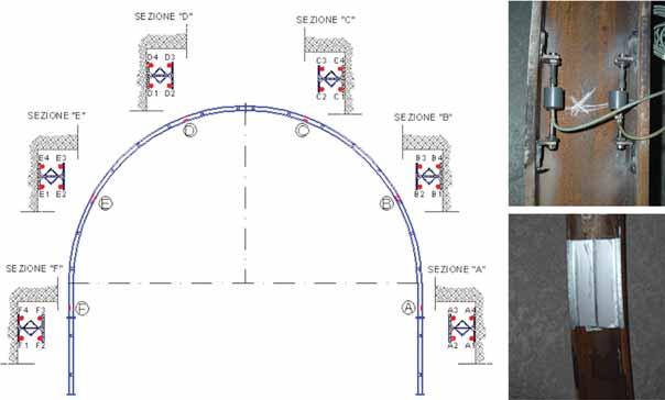
In conventional tunnelling, monitoring is primarily concerned with the stress and strain in the lining and with the geomechanical survey at the excavation face. The stresses and strains in the lining (both temporary and final) can be monitored by installing strain gauges on the steel ribs and load cells at the base of the ribs. Very often, the steel ribs are monitored with vibrating wire gauges that are considered as strain gauges, but are indeed a sort of stress gauge. A typical example of vibrating wire gauges bolted on brackets welded on the steel ribs is reported in Figure 11.1 (Bilotta & Russo, 2016).
Measurements of convergence (i.e. reduction in minimum distance between two points on the tunnel walls) are very important in conventional tunnelling, and for this reason, absolute and relative displacements of the temporary and of the final linings are usually monitored in a number of selected cross sections. Traditionally, convergence measurements were carried with the use of tape extensometer (made of steel or invar) connected by hooks to eyebolts positioned at different locations in the lining
Figure 11.1 Typical distribution of vibrating wire gauges bolted to the rib. (Modified after Bilotta and Russo 2016.)
cross section. Displacements are now frequently measured by a total station that detects the position of 5–7 targets located on the ribs or on the final lining immediately after their installations. During the subsequent excavation, the targets are read many times, following the monitoring plan. One or more benchmarks located very far from the face and nominally fixed (targets on the final lining are generally considered fixed) are read at the same time in order to obtain absolute values of the displacements. Any observed asymmetric response permits to identify the portions of the tunnel characterized by strain concentration. Millimetric accuracy and precision can easily be achieved.
An emerging technique used to monitor displacements is laser scanning. The laser scanner is nowadays employed for the localization of the preliminary support immediately before casting the final lining, to control its actual thickness at various locations along the section. The instrument is positioned close to the measuring area, and it is able to detect in few minutes the absolute position of the exposed surface (the position of the instrument needs to be geo-referenced). If repeated many times during the excavation, the evolution of the field of displacements can be obtained by comparison with the first measurement (Figure 11.2). The interpretation of the displacement field requires mapping algorithms. The technique requires good lighting conditions. In the best overall conditions, the accuracy may be of the order of few millimetres.
As per face monitoring, two main types of activities are usually carried out: geomechanical surveys of the face and extrusion measurements (longitudinal displacement measurements into the nucleus beyond the face as the excavation proceeds). The main goal of these surveys is the evaluation of the geological characters of the encountered rock mass. Surveys can be performed at different levels of detail and allow identifying the geological and geomechanical characteristics of the face, aiming to detect and control the variability along the advancement of the excavation and also checking the compliance with the geological model defined at the design stage. S urveys can be carried out beyond the excavation face by means of exploratory adits or sub-horizontal
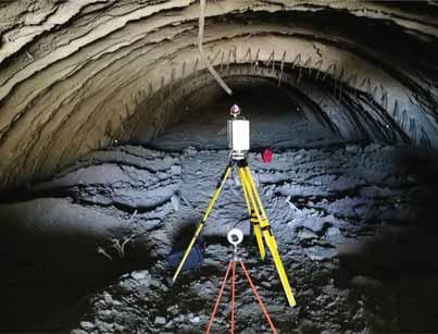
Figure 11.2 Laser scanner monitoring. (Courtesy of Anas S.p.A.)
boreholes. These solutions can be motivated by the need to ascertain in proper advance the possible presence of soil and rock masses with poor mechanical properties (e.g. fault zones) or the risk of water inrushes. Samples can be taken from the excavation face for laboratory tests, and also fast in-situ tests can be carried out, such as point load or uniaxial compression tests.
Extrusion measurements, usually recorded using incremental sliding micrometers, provide useful information regarding the soil response to the excavation. A plastic pipe equipped with magnetic elements is grouted to the ground inside a borehole drilled into the nucleus approximately along the tunnel axis. The comparison of the relative distance between the magnetic elements, measured inserting a sliding micrometer inside the pipe, after each excavation step, allows obtaining the extrusion curve (an example is reported in Figure 11.3). Differently from displacement measurements, which are a useful tool to evaluate the effects of soil–support interaction once the temporary supports are installed and the face moves further away, extrusion measurements enable to observe the response of the soil/rock mass of the nucleus before its excavation.
The extrusometer is usually installed in a borehole drilled into the nucleus destroying the core. In this case, DAC test technology should be used during drilling to indirectly acquire information about the mechanical properties of the rock massif, by recording perforation parameters such as velocity, torque and energy (Boldini et al., 2018). In the case of continuous core drilling, further information can be obtained from the samples extracted. Furthermore, before the installation of the column for extrusion measurements, video inspections of the hole can be carried out and further information about the number, nature and orientation of discontinuities of the rocks can be obtained. This information is essential to better identify the expected scenario as the excavation restarts (this is particularly important in the presence of faulted zones, water at high pressure and gas) and enables to take informed decision about how to excavate and the auxiliary works that should be implemented, if any.
11.2.1.2 Mechanized tunnelling
When preliminary support and final cast-in-place linings are employed, as for conventional tunnelling, criteria and instruments for monitoring the state of the lining are similar to those described in the previous section. For precast reinforced concrete segmental lining, the segments should be preliminarily equipped with strain gauges,
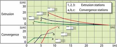
Figure 11.3 Example of extrusion measurements by means of a sliding micrometer combined with convergence measurements (Lunardi, 2008).
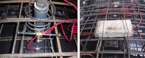
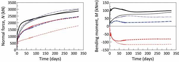
attached to the steel cage, in order to measure local deformations from which the state of stress can be inferred (Figure 11.4a). In these applications, vibrating wire gauges are often used, and in the last years, optical fibres have gained a significant slice of the overall market. Interpretations of these measurement are not straightforward, and internal forces may be derived only with accurate recording of the overall installation procedure of the segmental lining (Bilotta & Russo, 2013). Using pressure cells installed on the extrados of the segmental lining (Figure 11.4b), it is possible to measure the contact stresses arising from the soil–structure interaction. This type of monitoring, as all the contact measurements are carried out at the interface between different materials, is not always successful due to the stiffness of the instruments – i.e. the pressure cells – that may affect the quantity to be measured. Figure 11.5 shows a typical evolution of internal stresses in the segmental lining after the installation due to consolidation processes in clayey soils. Note that 1 year after the installation, the process is still ongoing. Although the convergences are usually very small, and their measurement is less important than in conventional excavation (especially for temporary support), displacements are systematically measured. Absolute displacements are rarely relevant. As an example, the absolute displacement can be relevant when a tunnel portion is directly involved in movements caused by external factors, for instance a landslide. Due to the presence of the backup, in mechanized tunnelling it is quite difficult to
(a) (b)
Figure 11.4 Precast lining segments monitoring instruments: (a) strain gauges attached to the steel cage; (b) load cell for contact pressure measurements. (Courtesy of Geotechnical Design Group s.r.l.)
Figure 11.5 Stress evolution in the precast lining due to consolidation processes (Genzano hydraulic tunnel in central Italy; modified after De Gori et al. 2019.)
timely install the monitoring system to measure displacements immediately after the installation of the lining.
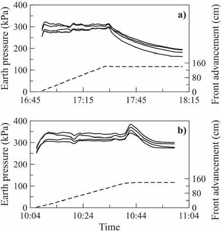
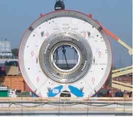
Tunnel boring machines require advanced managements and controls procedures (Maidl et al., 2013) during the construction phase, usually included in an overall risk management approach. Therefore, a long list of operational parameters is monitored in real time by modern TBMs (AFTES, 2005; ITA/AITES, 2011). These parameters are monitored both for avoiding damages of the TBM, which will be explicitly discussed in the following, and for the possible effects at the surface on existing structures (see Section 11.2.2). For TBMs operating in closed mode, both slurry shields (SS) and earth pressure balance (EPB), the face pressure, evolving over time and during different excavation phases, is the prominent parameter and it is monitored through pressure cells specifically installed in the excavation chamber (ITA-AITES, 2016). Thrust, torque, penetration, flow and properties of the slurry for SS technology and soil conditioning parameters for EPB technology, volume and pressure of grout injection are also important and monitored. The weight of the excavated muck for each advancement is another relevant measured parameter. Figure 11.6 reports an example of earth pressures in the excavation chamber measured during drilling and the subsequent standstill phase for the lining installation; the charts show the purposeful management of earth pressures aimed at minimizing tunnelling-induced settlements as the excavation nears the Carducci School in Rome (Miliziano & de Lillis, 2019). In terms of safety, it is important to outline the role of some measurements as, for example, the pressure in the excavation chamber. Sudden changes in these parameters should be carefully monitored because of the potential adverse effects on the surrounding soil and on the above structures and buildings.
For TBMs operating in open mode (as rock TBMs), since a frequent access to the tunnel face could be considered, the direct cutterhead consumption level and the geological examination of the excavation tunnel face could be included in the monitoring protocols (Zou, 2017).
c)
Figure 11.6 Earth pressure measurements inside the excavation chamber (a) far away from and (b) near the Carducci School (Miliziano & de Lillis, 2019); (c) pressure sensors’ position in an EPB TBM. (Courtesy of Roma Metropolitane s.r.l.)
During closed-mode tunnelling, measurement at the tunnel face cannot be obtained with the same type of procedures described for conventional tunnelling. That is because of course the tunnel boring machines forbid frequent access to the excavation face. In fact, this can only be accessed at the cost of a significant slowing of the advancement; thus, such operations are carried out only in particular situations. However, modern TBMs are equipped with drilling systems that allow forward prospecting at the face. The use of techniques of geophysical prospection beyond the face is also increasingly frequent.
As stated before, several important TBM operational parameters are constantly monitored during the construction process just to prevent and avoid possible damages to the machine. As a matter of fact, one of the priorities of the TBM monitoring system is to ensure the correct functioning of the TBM itself, preventing electrical faults, electronic malfunctions or mechanical failures in order to avoid temporarily or permanently compromising the tunnel construction. As an example, the breaking of the bearing is particularly feared because its replacement is a very complex task, expensive and time-consuming. Monitoring of power systems, working pressure, thrust cylinders, engines and temperature of all the mechanic components belongs to this category.
One of the further aims of monitoring TBM operational parameters is to evaluate in real time the excavation performance and possibly to improve it by modifying some of them. To this aim, TBMs are equipped with a complex multilevel monitoring framework connected in real time with a server allowing everyone involved in the project to have full access anytime and anywhere to all relevant information (clients, contractor, designer, suppliers, etc.). Within the framework are integrated:
• the positioning and tracking system which includes a navigation system, based on a total station and a target unit installed within the TBM shield, required to determine the current advance position; • the control system of the operating TBM parameters, able to monitor in real time the following quantities: all the main soil conditioning parameters, penetration/ advancement speed, cutterhead and screw conveyor rotation speeds, pressures at the face in the chamber and pressures in the screw conveyor, cutters wear/ consumption, weight of the material extracted from the excavation chamber, backfilling injection parameters (volumes and pressures), start and end times of the excavation and assembly phases of each rings, and clockwise and anticlockwise cutterhead rotation time. The analysis of all these parameters can be very useful to undertake actions to improve/optimize the excavation performance.
The monitoring framework allows to set an early warning system able to provide several alarms (through automatic acoustical signal, mail, text message and phone call) in case preset warning thresholds are exceeded.
11.2.2 Surface monitoring
Monitoring activities carried out on and near the ground surface aim at observing the ground response and the response of pre-existing structures and infrastructures to the
excavation. Clearly, surface effects grow larger as the depth of the tunnel decreases or its diameter increases; thus, the monitoring plan has to be designed accordingly.
The ground response can be observed referring primarily to displacements. Tunnelling-induced movements can be measured at surface using a variety of techniques: topographic, interferometric and high-resolution imaging.
• Topographic measurements: when settlements (i.e. vertical displacement) are the focus, precision optical or digital surveys may be selected as the best choice. These instruments are hand-operated and work on a network of invar steel brackets installed on the buildings and the structures to be monitored. The system when appropriately used is capable of high resolution and accuracy (i.e. submillimetric).
When displacements in all directions are needed, topographic measurements are made by using a total station working on a number of benchmarks or optical targets. The precision of this traditional technique is usually millimetric and depends on the system’s geometry (relative distances and angles between benchmarks and total station; Figure 11.7a) and on the overall installation layout. • Satellite interferometry: the technique is based on the phase modification of waves emitted by a satellite, reflected on the ground and detected back by the satellite.
The precision of the measurements is millimetric for displacements along the target–satellite alignment, while it is centimetric for the perpendicular displacement components. Hence, the technique is most suitable for the monitoring of settlements. Sometimes, the use of properly built and oriented corner reflectors is convenient, as it can significantly improve the precision of the technique. It should also be noted that when monitoring building displacements, this is seldom necessary as multiple pre-existing persistent scatterers can usually be identified. The main disadvantages are that satellite interferometry requires a complex numerical algorithm for the interpretation of the data and that the frequency of the measurement is based on the passage of the satellite above the monitoring area (usually weekly). An example of the results obtained from different satellite sensors is reported in Figure 11.7b.
a) b)
Figure 11.7 (a) Topographic measurement system installed to monitor displacements during an underground excavation in an urban area. (Courtesy of Geotechnical Design Group s.r.l.) (b) Interferometry results obtained from different satellite sensors (Mazzanti et al., 2020).
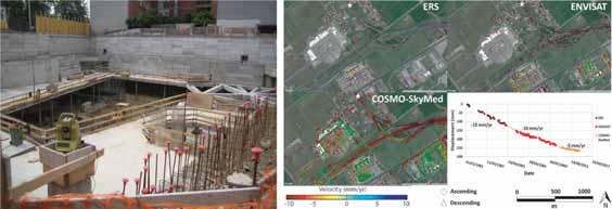
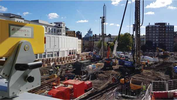
Figure 11.8 T errestrial interferometer installed (Mazzanti et al., 2020).
• Terrestrial interferometry: based on the same principles of the satellite interferometry, in this case the waves are generated by an antenna located on the ground, which is also capable of receiving the reflected waves. The precision is significantly higher (up to millimetric), and it is possible to measure accurately both vertical and horizontal displacements by properly placing the instruments (Figure 11.8).
It has the clear advantage of allowing free setting of the measurement frequency. • High-resolution imaging: this technique is relatively new and very promising; it is based on the comparison of high-resolution images taken at different times using advanced cameras. The cameras can also be installed on drones to perform aerial mapping. The accuracy depends strongly on a number of details that rarely can be controlled in large works with an expected long duration. Its application at the moment is still limited to small areas and on a relatively short-term basis.
Sub-surface movements can be measured installing extensometers and inclinometers into boreholes above and laterally to the tunnel. Single-point or multi-point extensometers (Mikkelsen, 1996) can be used to measure absolute and relative settlements along the tunnel axis and other verticals of interest, while inclinometers measure relative horizontal displacements along vertical alignments. In Figure 11.9, an example of a monitoring system tasked with measuring displacements from the surface is reported.
When variations of pore pressures are expected, the monitoring system should also include piezometric measurements; especially in the case of shallow tunnels, the instruments can be installed from the surface.
Buildings are typically monitored by observing, beyond the displacements, also the opening or width evolution of cracks (crack gauges), local tilting (clinometers) and relative displacements of selected points (hydraulic settlement gauges with precise pressure transducer). Hydraulic settlement gauges allow real-time monitoring of the
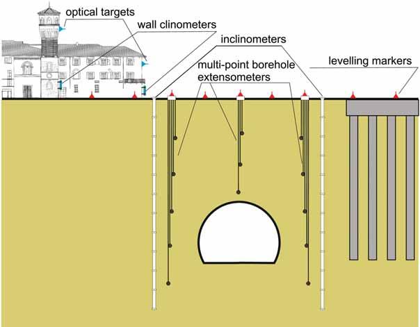
Figure 11.9 Schematic representation of a surface and sub-surface movements monitoring system. (Courtesy of C. Callari.)
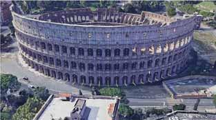
relative settlements of multiple points. They are systematically used when grouting compensation is carried out to minimize the induced settlements on existing buildings. Their accuracy is very high (millimetric). An example of a rich monitoring system is shown in Figure 11.10.
shaft Q18
mini-prism accelerometer clinometerleveling pins
Figure 11.10 Monitoring instruments installed on the Colosseum during the excavation on the new metro line C. (Modified after Romani et al. 2020.)
Another aspect of surface monitoring is that concerned with the tunnel entrance. In this case, monitoring activities are typically the same of those performed when dealing with open excavations. The main physical quantities that should be measured are the displacement of the excavation walls (in some instances, especially in urban areas, movements occurring above and behind the excavation walls are measured too) and the strains and stresses developing in the support elements (i.e. struts and anchors).
The same physical quantities are monitored in both conventional and mechanized tunnelling. The acquisition frequency is generally higher when TBMs are employed, due to much greater excavation rates.
In all cases, nowadays the tendency is towards automatic readings and real-time transmission of the monitoring data.
11.3 CALCULATIONS FOR MONITORING PURPOSES – WARNING THRESHOLDS
Ultimate limit state (ULS) calculations are carried out for safety evaluations following the approaches proposed by the Eurocode and other international codes. These approaches are usually based on the use of partial safety factors. In order to ensure adequate safety margins against collapse, minimizing the related risks, USL calculations are performed employing design values of soil mechanical parameters, obtained by reducing the characteristic values, and design load values, obtained by amplifying the characteristic ones (see Chapter 10). Thus, stresses and displacements associated with ULS calculations are conceptually and purposely overestimated if compared to the live conditions that will be monitored.
Based on the above, specific calculations should be carried out for monitoring purposes, assuming soil parameters and external loads in a range of variation close to the average most probable values (neither characteristic values, nor design ones).
Moreover, calculations should be aimed to follow the evolution of the relevant physical quantities (see Section 11.2) during the construction process. This allows to compare the expected values (predictions) with the measured values acquired during works, long before the most critical configurations are reached. A typical example, provided in order to clarify this concept, is the prediction of tunnelling-induced settlements on pre-existing building resting at the ground level. The calculation model should be able to predict not only the final values of settlements and distortions induced by tunnelling, but also how they evolve as the excavation face approaches the building, passes under it and proceeds further. When consolidation phenomena are expected in clayey soils, the prediction should of course take into account the time effects, evaluating the evolution of deformations and stresses until final drained conditions are reached. Creep effects on both soils and rocks require time effects to be taken into account, too.
In addition to the most probable expected range of values for each scenario and for each phase of the construction process, two warning thresholds for each measured quantity should be defined: attention and alarm thresholds. The alarm threshold should be determined by the designer, taking into consideration the needs of all the stakeholders involved (client and third parties) and the level of residual risk accepted by the owners/clients. The attention threshold is usually assumed as a percentage of the alarm one.
The alarm threshold is usually associated with a well-defined limit state. As an example, when tunnelling in urban areas, an alarm threshold is a precise level of damage induced on pre-existing structures. Frequently, this threshold is associated with a serviceability state. For example, the formation of few and small cracks that do not compromise serviceability or functionality, and do not require evacuation, can be accepted. Obviously, the alarm threshold is a function of the vulnerability of the structure to be protected and of its historical, monumental, or also strategic importance. Based on the acceptable level of the damage selected, maximum values of settlements and distortions at the foundation level are calculated and assumed as alarm thresholds. Other examples are the following:
• the limit state of deformation of temporary supports, for which the alarm threshold is the value of the maximum convergence admissible to avoid excessive reductions and consequent under-thickness of the final lining; • the limiting values of the stresses in the ribs employed for temporary support, for which the alarm threshold is usually determined as a percentage of the yielding stress.
The availability of monitoring data since the very beginning of the construction process allows re-calibrating the models adopted in the design stage within the typical process of the observational method. When the predictions obtained after the model re-calibration based on monitoring data (as further discussed below) are close to the attention threshold, works can proceed as planned, but greater attention should be paid (the measurements frequency can be increased, the prediction model can be finetuned, and some construction activities can be slightly modified). When the predictions overcome the alarm threshold, more relevant changes should be implemented during the construction (such as boosting the soil improvement, increasing the pressure applied to the face and closing the temporary support at the invert), in order to steer the values of the monitored quantities below the target maximum one (below the assumed alarm threshold). If the variation rates of the measured representative quantities do not cancel out in a reasonable time, the excavation operations must be stopped and the temporary countermeasures must be promptly applied as planned, to counteract the observed trend towards a potentially unstable tunnel behaviour. All the countermeasures deemed necessary for the protection of people inside and outside the tunnel will be implemented.
Thus, the values of the monitored quantities to be compared with the thresholds are usually re-calculated during the construction phase – taking explicitly into account the physical quantities recorded by the monitoring system and the new information acquired through surveys at the excavation face. They do not necessarily coincide with design predictions. The need and the opportunity for re-calibration of the models adopted at the design stage are clarified by the following example. Typically, the constitutive models adopted in practice for soils and rocks are simple and robust – i.e. linear elastic–perfectly plastic (with Hoek–Brown/Mohr–Coulomb or Tresca strength criterion) – and therefore, soil non-linearity, time effects (creep/viscous behaviour) and softening phenomena are often neglected. Hence, deformations/displacements and stresses that arise and their evolution are poorly predicted. Also, operational values of strength parameters and particularly of the stiffness of soil and rock masses are very difficult to assess
at the design stage. Moreover, the behaviour of the system is very much affected by rock non-homogeneity, anisotropy of mechanical properties and anisotropy of initial lithostatic state of stress. All of them are rather commonly encountered, very difficult to investigate and not susceptible of easy quantification and, finally, very difficult to account for in the calculation models usually adopted in practice. For all these reasons, the ranges of expected values should be re-calculated during works accounting for all the recorded data, including geomechanical surveys, and changing the operational values of the strength and of the stiffness parameters. Usually, for a geotechnical unit, the re-calibrated model can provide good prediction as the cover changes.
The improved accuracy of the updated predictions is useful to control the performance of the system in the deterministic design approach and crucial for a successful application of the observational approach.
11.4 CONCLUDING REMARKS
This chapter described the main aspects of the monitoring of tunnels during construction, focusing mainly on monitoring activities aimed at geotechnical and structural purposes. The monitoring plan, from the identification of the relevant physical quantities, to the definition of the suitable instruments and measurements technique, up to the interpretation of the recorded data, is a fundamental part of the project, ultimately aimed at further reducing residual risks. With the goal of providing the basic information useful for the development of the design and the monitoring plan, only a few information regarding the main monitoring techniques was given herein, briefly discussing their accuracy, applicability and limitations, and referring the reader to Book 2 for a more in-depth description.
It was remarked that specific calculations should be carried out in order to obtain predictions that are comparable with the measurements. To this aim, mechanical parameters and load values should not be reduced or increased through partial safety factors, but instead should reflect the most probable scenario. In addition, two warning thresholds – attention and alarm – should be defined for each relevant physical quantity being monitored and used as framework for the identification of the level of risk and its acceptability. These calculations should be performed for different stages of the construction, to compare predictions and measured values progressively acquired. If needed, as often is the case given the intrinsic difficulty of the task at hand, the model may be re-calibrated by back-analysing the monitoring data with the aim of updating and improving the predictions while the work is in progress.
Design, monitoring, back-analysis and re-prediction constitute an efficient engineering approach that enables to improve the understating of these complicated systems and constantly learn from experience.
AUTHORSHIP CONTRIBUTION STATEMENT
The chapter was developed as follows. Miliziano and Russo: chapter coordination. The chapter was joined developed by the authors. All the authors contributed to chapter review. The editing was managed by de Lillis and Sebastiani.
REFERENCES
AFTES (2005) Guidelines on monitoring methods for underground structures. Working Group
GT 19. AITES/ITA WG2-Research (2011) Monitoring and control in tunnel construction. ITA report no. 009/November 2011. Available from: https://about.ita-aites.org/publications/wg-publications/download/75_b0364940d7fbafd5a1b8564052aebb8b [accessed 15th January 2021]. Bilotta, E. & Russo, G. (2013) Internal forces arising in the segmental lining of an earth pressure balance-bored tunnel. Journal of Geotechnical and Geoenvironmental Engineering, 139(10), 1765–1780. Bilotta, E. & Russo, G. (2016) Lining structural monitoring in the new underground service of
Naples (Italy). Tunnelling and Underground Space Technology, 51, 152–163. Boldini, D., Bruno, R., Egger, H., Stafisso, D. & Voza, A. (2018) Statistical and geostatistical analysis of drilling parameters in the Brenner Base Tunnel. Rock Mechanics and Rock Engineering, 51, 1955–1963. Burland, J., Standing, J.R., Mair, R.J., Linney, L.F. & Jardine, F.M. (1996) A collaborative research programme on subsidence damage to buildings: prediction, protection and repair. Proceedings of the International Symposium on Geotechnical Aspects of Underground Construction in Soft Ground, April 15–17, London, UK. De Gori, V., de Lillis, A. & Miliziano, S. (2019) Lining stresses in a TBM-driven tunnel: A comparison between numerical results and monitoring data. In: Peila, D., Viggiani, G. and
Celestino, T. (eds.) Tunnels and Underground Cities. Engineering and Innovation Meet Archaeology, Architecture and Art. Proceedings of the WTC 2019 ITA-AITES World Tunnel Congress (WTC 2019), May 3–9, 2019, Naples, Italy. CRC Press, London. ITA-AITES, German Tunnelling Committee (2016) Recommendations for face support pressure calculations for shield tunnelling in soft ground. Available from: https://www.daub-ita. de/fileadmin/documents/daub/gtcrec1/gtcrec10.pdf [accessed 1st March 2021]. Lunardi, P. (2008) Design and Construction of Tunnels: Analysis of Controlled Deformations in
Rock and Soils (ADECO-RS). Springer-Verlag, Berlin Heidelberg. Maidl, B., Herrenknecht, M., Maidl, U. & Wehrmeyer, G. (2013) Mechanised Shield Tunnelling.
John Wiley & Sons, New York. Mazzanti, P., Moretto, S. & Romeo, S. (2020) From the sky to underground: New Remote Sensing solutions in tunnelling and excavation works. Gallerie e Grandi Opere Sotterranee, 135. Mikkelsen, P.E. (1996) Landslides: Investigation and mitigation. Chapter 11- Field instrumentation. Transportation Research Board Special Report, 247. Miliziano, S. & de Lillis, A. (2019) Predicted and observed settlements induced by the mechanized tunnel excavation of metro line C near S. Giovanni station in Rome. Tunnelling and
Underground Space Technology, 86, 236–246. Romani, E., D’Angelo, M., Foti, V. & Sidera, L. (2020) Metro Line C in Rome: Two different case histories for the comparison between the design predictions and the experimental data acquired by the monitoring system during the TBM tunnels construction. Gallerie e Grandi
Opere Sotterranee, 135. Zou, D. (2017) Monitoring and instrumentation for underground excavation. In: Theory and Technology of Rock Excavation for Civil Engineering. Springer, Singapore. https://doi. org/10.1007/978-981-10-1989-0_22.


