35 minute read
12 Maintenance and refurbishment of existing tunnels
Maintenance and refurbishment of existing tunnels
S. Miliziano and A. de Lillis
Advertisement
Sapienza University of Rome
S. Santarelli
Consultant
CONTENTS
12.1 Introduction .....................................................................................................333 12.2 Degradation phenomena and damages ...........................................................334 12.3 Inspections and monitoring .............................................................................336 12.3.1 Inspections ............................................................................................337 12.3.2 Monitoring ...........................................................................................339 12.4 Maintenance activities, repair works and protective measures .......................340 12.5 Refurbishment works .......................................................................................341 12.5.1 Methods ................................................................................................342 12.5.1.1 Water control ..........................................................................342 12.5.1.2 Structural improvement ..........................................................344 12.5.2 Design ...................................................................................................346 12.6 Concluding remarks ........................................................................................347 Authorship contribution statement ...........................................................................348 References .................................................................................................................349
12.1 INTRODUCTION
The extensive construction of tunnels started at the end of the 19th century as a consequence of the railway development and after the diffusion of hydroelectric power plants. Roughly at the same time, the construction of urban tunnels for subways and road tunnels for the urban development started. In the second half of the 20th century, the development of motorways prompted the construction of a large number of road tunnels, including very long ones across the Alps.
During this long period of time, the construction methods evolved in terms of both excavation techniques and lining types and materials. The stone elements initially employed for the construction of the linings were progressively replaced by bricks, concrete, reinforced concrete and reinforced concrete precast elements.
With time, several degradation phenomena started to appear – induced by the action of natural agents, the ageing of the materials and the use of the tunnels and
DOI: 10.1201/9781003256175-12
accelerated by construction defects – and required the implementation of systematic maintenance activities and reparation works.
Maintenance is a very important activity. A good maintenance enables good operational performances and increases the life of the tunnel. Thus, a day after the beginning of tunnel operations, the maintenance programme should start. Since the evolution of the state of the lining, as in general that of physical and mechanical properties of all materials employed, depends on a number of factors, this is quite difficult to predict accurately at the design stage. Therefore, the lining’s state evolution should be kept under observation by means of systematic inspections and monitoring activities (ITA, 1995). Thus, the maintenance programme developed at the design stage should be constantly updated. During the tunnel operational life, a surveillance system should be implemented, with the aim of controlling the evolution of the state of the lining.
Maintenance, repair and refurbishment works can only be properly planned if detailed information about the state of the lining and the evolution of defects and degradation phenomena are available. The main goals of the maintenance and repair works are to set the conditions for a safe use, to extend the tunnel operational life and to safeguard the external environment, while keeping the interference with its use at a minimum. However, after a long time, systematic maintenance interventions and repair works can become so frequent and important that it may be better, as a result of a cost–benefit analysis, to consider a complete refurbishment of the tunnel to properly restart its operation life. It is also worth noting that the experience acquired carrying out maintenance activities can improve the design criteria for tunnels, reducing future maintenance and increasing the operational life.
After a brief description of the main damages and causes of degradation generally encountered in tunnels, this chapter illustrates the activities – inspections and monitoring – necessary to keep tabs on the evolution of the state of the tunnel. Maintenance, minor repairs and protection measures works are then briefly mentioned before a detailed description of refurbishment works. The more frequently employed refurbishment methods are illustrated, together with the design approach followed in refurbishment projects. Readers looking for further details regarding materials and technologies are referred to Book 2.
Widening of existing tunnels (Lunardi, 2003), re-profiling works and maintenance and refurbishment of electrical or ventilation plants, or other secondary systems, are out of the scope of this chapter and therefore are not addressed herein. Interested readers can find further information on these topics in Books 2 and 3.
12.2 DEGRADATION PHENOMENA AND DAMAGES
The structural capacity of the lining, due to constructive defects – which can be minimized, but not entirely avoided – is always inferior to the design one. This is particularly true for old tunnels, constructed adopting underdeveloped technologies and lacking adequate quality controls. Furthermore, the lining strength is bound to decrease in time. The durability of the lining and, in general, of all the materials employed is affected by several degradation factors, among which the most prominent are
humidity, temperature (both average values and variations in time), use and intensity of use, nature of the surrounding soils/rocks, water table (both height and oscillation), chemical composition of water, frost, etc. Finally, the lining can be damaged by natural phenomena not duly considered in the project (consolidation processes, creep behaviour, etc.) or rare events such as earthquakes, landslides and fires. In this section, a brief description of the most common constructive defects and of the main causes of structural degradation is reported.
Constructive defects: constructive defects are related to imperfections in the construction of the tunnel. Regarding cast-in-place concrete linings, the main defects are honeycombing, formation of cavities or discontinuities due to casting interruption, and under-thickness. The development of cracks due to shrinkage or to thermal strains in the absence of sufficient expansion joints can be ascribed to constructive defects as well. Regarding reinforced concrete, other defects can be due to the wrong placement of the steel bars, inducing excessive or insufficient concrete covers.
With respect to precast lining segments, defects in the concrete or in the placement of the bars are quite rare due to accurate quality controls implemented at the production facilities. In this case, the main defects are associated with the stripping from the formworks, storage, transportation and assembling (assembling mistakes or jacks thrust) of the segments. Once the lining is put in place, further damages can be induced by stress states different from those assumed in the design or by defects in the grouting of the tail void. Finally, other defects are connected with the waterproofing; the circulation of water through joints or cracks, in fact, contributes to the acceleration in the degradation processes.
Material degradation: the degradation of the concrete is mainly a consequence of carbonation reactions, in which the carbon dioxide in the environment reacts with the calcium hydroxide in the cement. Carbonation induces a progressive worsening of the mechanical characteristics and increase in the permeability. Carbonation is widespread in road and rail tunnels – due to greater air circulation and exposition to exhaust fumes – while it is almost absent in hydraulic tunnels, especially if pressurized. In hydraulic tunnels, degradation phenomena are mainly associated with the scouring or the erosion due to the water flow.
The corrosion of the reinforcements is another relevant degradation phenomenon that can be worsened by natural or anthropic stray currents, sometimes even induced by the activities in the tunnel as for rail tunnels. The corrosion induces a progressive reduction in the bar thickness and a loss of adherence and also favours concrete detachments. These processes are part of the natural ageing of the tunnels; they can be minimized with regular maintenance, but cannot be entirely eliminated.
Lining degradation phenomena, both carbonation and steel corrosion, which generally proceed very slowly, are accelerated by the infiltration of water (ITA, 1991). Water infiltration can also facilitate the intrusion of chemical and biological contaminants that can further contribute to degrading concrete and corroding steel bars. The presence of construction defects accelerates the degenerative processes, too. Cracks and discontinuities, in fact, allow the steel bars to get in contact with the air, and eventually with the circulating water, and increase the exposed concrete surface.
Damages: beyond the slow degradation due to the above-mentioned physical and chemical phenomena, tunnels can suffer significant damages – ranging from cracks to
detachments to potentially catastrophic instabilities – due to the occurrence of other events. The following is a brief synopsis of the more widespread causes of the damages.
Earthquakes: on the ground surface, seismic actions are much more severe than they are at depth due to the amplification effects. Nonetheless, seismic- induced loads can cause significant damages to the tunnel linings, especially those realized in masonry or without reinforcements. The damages are usually much more pronounced near the entrances of the tunnel (low covers and, often, poor soils), near zones characterized by large differences in stiffness (soil/rock contacts or fault zones) and near active faults crossing the tunnel, when permanent relative displacements develop due to seismic events.
Landslides: structural damages that in extreme cases can even lead to the loss of the tunnel may occur when the tunnel is involved in a landslide (or when the excavation of the tunnel itself reactivate or accelerate a landslide as in the case of the Val di Sambro Tunnel; Bandini et al., 2015). These phenomena are usually more significant for low-cover tunnels; thus, the entrance zones are generally more susceptible.
Changes in the loads acting on the lining: when tunnels are excavated in soils characterized by poor mechanical properties, significant swelling, creep behaviour or delayed response, the effects of the construction evolve with time, changing the shorttime equilibrium of the soil–structure interaction and the loads acting on the lining. If the change in the lining loads is not correctly evaluated at the design stage, the stresses can exceed the lining strength inducing unacceptable deformations or the formation of cracks. In extreme cases, the stability of the system may be in jeopardy and onerous structural works may be needed.
Nearby constructions: the evolution of the stress and strain state induced by new constructions near the tunnel (excavation, embankments, twin tunnels, etc.) can induce significant damages to the lining. Especially in poor ground conditions, the generally acceptable three-diameter distance may not be sufficient and the induced damage can be considerable and even potentially dangerous for the users.
12.3 INSPECTIONS AND MONITORING
The evolution of the state of every tunnel should be kept under control during its entire operational life. Thus, it is crucial to check the state of the lining, the formation of cracks and the evolution of their length and width, the changes in the strength of the materials following concrete carbonation/degradation or reinforcements’ corrosion, etc. Since one of the goals of maintenance is to minimize the risks to the users, detachments and falling of structural and non-structural elements (ventilation systems, lighting systems, etc.), platform deformations and water inflows (both quantity and quality) should also be monitored. To these aims, the implementation of inspections and monitoring systems – whose combination forms a complete surveillance system – can provide the information required to guarantee serviceability and safety.
All the information gathered from the inspections and the monitoring instruments should be archived and handled using a tunnel management system (TMS) based on BIM or GIS. The TMS should also contain other relevant information regarding the tunnel (as-built, maintenance and repair activities, etc.). Beyond making promptly available all these pieces of information, the TMS should be a tool for scheduling
maintenance activities and inspections, installing monitoring instruments, carrying out refurbishment works, etc. More in general, the TMS has a twofold function: that of a dedicated database and that of a useful instrument to guide the decision-making and the overall management of the tunnel.
12.3.1 Inspections
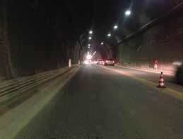
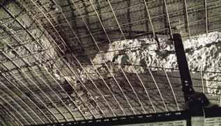
Inspections should be carried out periodically, as part of the maintenance programme. The inspection frequency can vary depending on the specific state of the tunnel. Inspections should also be carried out immediately after every relevant natural event, such as landslides, floods or earthquakes, occurring near the tunnel. On this subject, several recommendations and codes have been drafted by specialized bodies and national authorities (CETU, 2012, 2015a, b; MIT, 2020; Sétra, 2010). Defects and damages detected during inspections can be classified according to one of several classification systems available. For instance, the IQOA (Image Qualité des Ouvrage d’Art; CETU, 2015a) proposes a classification accompanied by indications about possible actions to be implemented (waiting/no action, maintenance and minor repair works, service interruption and major refurbishment, etc.). Figure 12.1 reports some typical tunnel damages. In the following, a distinction is made between visual and instrumental inspections.
(a) (b)
(c)
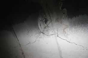
Figure 12.1 Examples of typical damages: (a) network of cracks; (b) road platform uplift and deformations; (c) spalling, concrete detachment. (Courtesy of Geotechnical Design Group srl.)
Visual inspections should be carried out by experienced engineers, whose expertise comprises tunnelling, lining behaviour and the use of the tunnel. Expertise is necessary because the possible effects of leakage and structural degradation of the lining are quite difficult to predict and because non-visible damages are not easily detected: for instance, extensive damages/corrosion of the reinforcements, induced by small water leaks through thin cracks, can develop over time without appreciable clues on the visible side of the lining. The inspections aim to detect damages and properly assess their severity. To enhance the effectiveness of the inspections, it is convenient to periodically clean the lining beforehand using pressurized water (the exercise should be temporarily limited or suspended). Following inspections, further investigation can be prompted if more information is needed, or operational decisions can be taken for safety reasons.
The survey of the network of cracks is an important tool for the identification of potential collapse mechanisms.
The evaluation of the current state of drainage pipes, drainage channels, fans and lighting devices should also be carried out to guarantee the safety of the users.
Every point of water inflow and all humidity areas should be detected and mapped. The comparison with the previously detected areas can provide precious information regarding the evolution of the state of the lining.
The state of the concrete can be quickly investigated using the hammer: sound differences are in fact useful to identify degraded areas and local discontinuities, which could induce concrete detachments. Video inspections, inexpensive and very useful, can also be carried out using micro-cameras inserted inside small-diameter drilled holes, in order to detect discontinuities, delamination surfaces, cavity, etc.
Visual inspections usually entail meaningful interference with the ordinary use of the tunnel. In the case of road tunnels, the inspections are usually carried out in night-time, temporarily suspending the use of the tunnel; in railway tunnels, night inspections can generally be carried out with little to no interference; in hydraulic tunnels, it is obviously necessary to temporarily put the tunnel out of service.
Instrumental inspections can be carried out using laser scanning, thermal scanning and high-resolution imaging techniques. Laser scanning and high-resolution imaging allow acquiring detailed and georeferenced images of all visible elements inside the tunnel and provide both qualitative and quantitative information regarding the state of the tunnel, the networks of cracks, detachments, deterioration, etc. Thermal scanning techniques are primarily concerned with the presence of water and allow detecting areas with different levels of humidity. An example of images resulting from these techniques is reported in Figure 12.2.
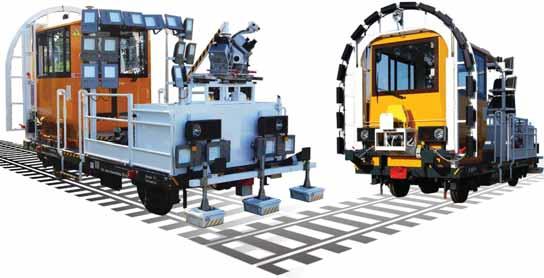
Modern instruments acquire data at a rapid pace and can be easily mounted on road or rail transportation moving at 3–30 km/h, depending on the requested accuracy (Figure 12.3). Thanks to these characteristics, in road and railway tunnels, the system can operate with just minor interference to the traffic (in hydraulic tunnels, instead, it is necessary to temporarily put the tunnel out of service).
Recently, several software applications have been developed to allow the generation of 3D virtual reality environments based on scanning and imaging data. Tools such as these can be highly effective to remotely carry out very realistic virtual inspections.
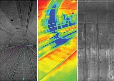
Figure 12.2 Images obtained with laser scanning, thermal scanning and high-resolution imaging technologies. (Courtesy of ETS srl.)
Figure 12.3 Laser scanning, thermal scanning and high-resolution imaging instruments mounted on rail transportation (Foria et al., 2019).
Irrespective of the type of inspection, attention should always be paid to the road/ rail platform; uplifts and deformations, in fact, can be precursors of instability problems and are very dangerous for the users.
12.3.2 Monitoring
The monitoring of tunnels can be performed by periodically and systematically acquiring relevant data. The comparison between the results of subsequent inspections
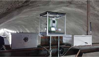
Figure 12.4 Topographic monitoring via automatic total station. (Courtesy of Leica Geosystems.)
is, in fact, a useful way to keep tabs on the state of the tunnel. The comparisons allow observing the evolution of the networks of cracks (both opening and width), detachments, humidity areas, etc. If laser scanning technologies are employed, the comparison with previous measurements can also be used to quantify the field of displacements and its evolution over time. The comparison of the results of periodic in situ and laboratory tests – such as pull-out tests, concrete carbonation tests, flat jack tests, uniaxial compression tests on concrete specimens or tensile strength tests for the steel bars – can be used, too, to assess the evolution of the state of the lining.
Depending on the specific situation, or if the inspections detect something that deserves continuous attention, instrumental measurements can also be implemented to carry out periodic readings. The main physical quantities usually measured in tunnels during operations are crack width (using crack gauges), state of stress of the lining (using strain gauges and load cells), displacements or convergence (using automatic total stations, reported in Figure 12.4, or optical fibres), pore pressures in the ground close to the tunnel (using piezometers) and the amount of water collected by the drainage system.
In some cases, real-time monitoring can be prescribed. This is, for example, the case of shallow tunnels involved in slow-moving landslides. Typically, from inside the tunnel, displacements, cracks opening and local stresses are monitored, while, outside the tunnel, surface and sub-surface displacements and pore pressure are recorded. The measurements can be carried out with high frequency and transmitted in real time for analyses. In these cases, early warning thresholds are usually preset and associated with well-defined actions (visual inspection, exercise suspension, etc.).
For more detailed information about monitoring technologies, instruments, limitations, accuracy and precision, the reader is referred to Volume 2.
12.4 MAINTENANCE ACTIVITIES, REPAIR WORKS AND PROTECTIVE MEASURES
Ordinary maintenance activities generally consist in light works such as painting steel to protect from corrosion, replacing support elements of the ventilation and lighting
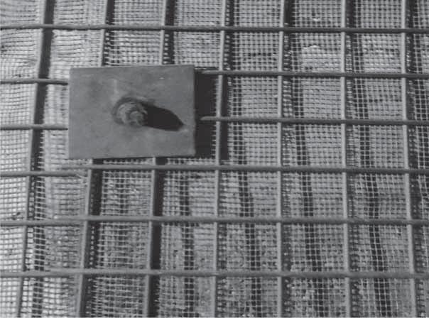
Figure 12.5 Installation of two steel nets of different grid sizes bolted to the lining to retain detached elements.
systems and cleaning of the drains and drainage channels (CETU, 2012; ANAS, 2018). Ordinary maintenance can include minor repair works which are generally local and address the safety of the users: removing concrete pieces of the lining in precarious stability conditions, treating the steel bars with anti-corrosion products, replacing the concrete cover with special protective mortar and sealing of concrete cracks by grout injections (cementitious mixtures or chemicals). Repair works are usually very fast and not expensive and can be carried out with minimum or no interference with the use of the tunnel (ITA, 2001).
When the safety cannot be guaranteed with acceptable residual risks by carrying out minor repair works, temporary passive protection systems should be implemented until major refurbishment works can be carried out. Among these are the installation of steel nets at the crown of the tunnel, adequately bolted to the lining, to minimize spalling risk by retaining detached elements (Figure 12.5), or the installation of drainage channels to avoid water flowing into the tunnel. However, the use of drainage channels should be limited to localized leakage areas (joints) and to short periods of time – until waterproofing works can be realized or draining pipes are installed – to avoid concealing the lining, which should always be visible to allow direct observation.
Irrespective of the kind of works, the available data should be sufficiently detailed to allow the identification of the causes of the damages, thus enabling to select the more appropriate repair method to directly address the root causes.
12.5 REFURBISHMENT WORKS
More extensive than ordinary maintenance activities can be classified as refurbishment works. At the end of its operational life, or in any case when the functionality or the operational safety is no longer fully guaranteed (due, for instance, to unacceptable risks and maintenance cost or excessive water leakage for hydraulic tunnels), the
tunnel must be put out of service or extraordinary refurbishment works must be carried out. Refurbishment works generally involve the whole tunnel and aim to improve the tunnel structure (static reasons due to material degradation, requirements of new technical rules, etc.) or geometry (functional needs and operational aspects) and to organize and control the water flow (waterproofing and drainage systems), creating the conditions for a safe use, safeguarding the external environment and prolonging the life of the tunnel. Refurbishment works are very costly and time-consuming and usually require the suspension of tunnel operation.
The design of refurbishment work requires a thorough definition of the problem and the correct identification of the root causes of the damages. Remedial actions, whenever possible, should be addressed towards the elimination of the causes of the damages and not just towards temporary repairment. To identify the causes, all available data should be carefully analysed and specific surveys and investigations should be carried out.
Refurbishment works also offer the opportunity to implement further safety measures (possibly required by updated national codes) such as bypasses or escape routes. These topics, together with the complete demolition of the existing lining for re-profiling works, go beyond the scope of this chapter and therefore are not discussed.
12.5.1 Methods
In this section, the methods usually adopted to carry out refurbishment works are described. A distinction is made between water control works and structural works. Since the refurbishment methods are quite similar, independently of the lining’s nature (precast reinforced concrete segments and both plain and reinforced cast-in-place concrete), no distinction is made between mechanized and conventional tunnelling.
12.5.1.1 Water control
As discussed above, the main cause of lining degradation is the infiltration of water. In fact, degradation phenomena will generally proceed very slowly without water’s damaging effects. Therefore, the elimination of all sources of leakage is paramount for the safeguard of the tunnel.
Several methods can be employed to eliminate water leakages or their dangerous effects. Suitability and effectiveness of these methods can also depend upon the lining’s nature.
A first method, suitable where controlled drainage is acceptable, consists in collecting all the water inflow using drainage pipes. The collected water is then conveyed towards a water sump for disposal through the main drainage system running through the invert for the whole length of the tunnel. The drainage pipes should be able to capture the water at the extrados of the lining in order to avoid it coming in contact with the concrete. The pipes should also be protected using geotextiles, to avoid the transportation of fine solid particles. A separate drainage system should be used to capture the platform water, which needs to be treated before disposal. Finally, periodic maintenance activities should be carried out or, if not possible, the pipes should
be monitored and replaced when necessary. All these activities can be performed from inside the tunnel.
Drainage channels address the same need of water control. However, although inexpensive and rapidly installable, drainage channels should only be employed as temporary measures, as it is far preferable to capture water before it leaks through the lining, progressively contributing to the material’s degradation.
An opposite strategy is that of waterproofing the lining through grout or chemical injections. The injections should be mainly concentrated along the surfaces of structural and constructive joints, where leakage usually occurs. If present, cracks should be treated to make the lining impervious (injecting the cracks also constitutes a structural repairment which increase strength and durability of the concrete). The injections must be done in more than one session, starting from the leaking points and then addressing the new leakages that form after the closing of the first ones. In such cases, it is preferable to make the lining impervious injecting at its extrados to avoid that filtrating water comes in contact with the internal concrete.
Very similar techniques and materials can be used to inject the joints between the precast lining segments. Furthermore, in this case, the injection of the tail void during mechanized construction (carried out to completely fill the void annulus) can greatly contribute to achieving the requested level of hydraulic tightness. Different products can be used: cementitious mixtures, and chemical products such as resins of different physical and mechanical characteristics and costs (refer to Book 2 for further details).
It is worth specifying that in the case of deep tunnels, sealing works should be realized in conjunction with draining systems, while for shallow urban tunnels, waterproofing is usually mandatory. In some cases, due to environmental prescriptions (mainly to preserve aquifers at risk), it can be necessary to resort only to waterproofing even for relatively deep tunnels.
Another frequently adopted method consists in creating an internal re-lining, which can become part of the original lining. This method can be successfully applied to seal leakages characterized by very small water inflows. The re-lining is usually carried out by removing a few centimetres of the lining, collecting water with small draining pipes and then spraying a thin layer of shotcrete, possibly reinforced with fibres or with electro-welded meshes. Alternatively, it is also possible to use PVC membranes nailed to the existing lining (special precautions must be taken to guarantee watertightness where the nails pass through the membranes) or even sprayed waterproofing membranes. The secondary lining, if properly reinforced, can also play an important role from a structural point of view (see the following). Finally, another option is that of carrying out the re-lining by using prefabricated shells, separated from the existing lining, covered by a PVC membrane. This last method, however, definitively conceals the original structural lining which cannot be maintained or inspected any longer, and therefore, it is not advised.
All the previous methods involve works carried out from inside the tunnel. Another possible course of action that only involves operations from outside the tunnel consists in removing the source by lowering the water table permanently. This can be accomplished using gravity drainage systems such as sub-horizontal draining pipes or draining wells. In this case, it is crucial to set up a monitoring system, possibly automated, able to signal malfunctioning in real time.
The above methods can be employed in conjunction and together with works aimed at structurally improving the lining.
12.5.1.2 Structural improvement
There are several viable methods for the structural improvement in the tunnel. The choice of the most appropriate method depends on many factors related to the current state and function of the tunnel (e.g. severity of damages, type of lining, tunnel use and environmental settings) and to the requested characteristics (e.g. strength and durability of the materials and works duration). Irrespective of the adopted technique, before proceeding with structural improvements, it is always advisable to carry out the water control works selecting one of the methods discussed in the previous section.
The most effective structural improvement technique consists in constructing an internal re-lining of reinforced concrete. When a reduction in the internal profile of the tunnel is admissible, the new lining can be made in contact with the existing one by using cast-in-place concrete and properly designed formworks. If the water table is absent, specific waterproofing systems can be avoided and a good concrete mix design, cast with great care, will result in an impervious enough lining. In any case, structural joints between segments must always be prescribed in order to avoid the formation of cracks due to concrete shrinkage during curing and thermal deformations. Nonetheless, the use of an impervious membrane attached to the existing lining is always advisable; alternatively, a sprayed waterproofing membrane can be employed. These measures protect the concrete and the reinforcements from percolating water leaking through the joints and the cracks of the existing lining. The reinforcement can be made of a classic steel cage, metallic fibres or both. Electro-welded wire meshes and lattice girders are frequently employed, too.
Shotcrete can be also employed instead of ordinary cast-in-place concrete for a very fast construction, using alkali-free accelerators for durability reasons. In this case, if impervious PVC membranes have been installed, it is necessary to use systems to allow the adhesion of the shotcrete, minimizing the rebound phenomena, such as wired meshes in contact with the membrane, and the shotcrete must be sprayed multiple times, thus creating overlapping thin layers. Further information on this topic can be found in several handbooks (e.g. Sika, 2020). Finally, it is also advisable to use steel support elements (lattice girders) to strengthen the lining and ensure the final tunnel profile.
When a reduction in the internal profile is not admissible, or a small increment is necessary, before the construction of new internal lining the existing one must be preliminarily demolished. Two different methods can be employed. Hydro-demolition can be adopted, which is an efficient, cost-effective and precise method that removes concrete with jets of high-pressure water. Alternatively, a portion of internal lining can be milled mechanically by means of specially designed roadheaders (Figure 12.6). In the presence of reinforced concrete, before milling the steel bars must be cut. To minimize the amount of dust produced, the machines are equipped with special protection caps and numerous water-spraying nozzles (ventilation and dust-processing systems must be prepared carefully, too).
a) b)
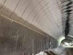
Figure 12.6 Mechanical milling of the internal lining concrete aimed at re-lining the tunnel. (Courtesy of CIPA SpA.)
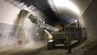
Usually, few decimetres of new, good reinforced concrete lining are generally enough to guarantee the requested margins of safety against general collapse mechanism and local instabilities (collapse of pieces of concrete of the lining). After milling, the works can proceed as described above for the simple internal re-lining (without milling): elimination or control of water inflows, installation of a waterproofing system, installation of reinforcements and casting of concrete.
For both safety and construction site reasons, usually, the works are carried out slowly, operating segment after segment. This can be necessary, for instance, when the lining is realized with reinforced concrete and is heavily loaded and the thickness of the remaining portion of the lining after milling is relatively thin.
A complete structural connection between the new lining and the existing one is practically impossible to realize, especially when waterproofing membranes are used. Nonetheless, even if the two linings can only exchange normal forces/stresses, the composite system can work quite well, guaranteeing the required safety conditions.
It is important to note that, frequently, the new lining will be essentially unloaded. In most cases, during their operational life, the new linings are only stressed in the occasion of rare events such as earthquakes, vehicle impacts and fire. They are mainly tasked with a prevention/protection role, lasting as long as possible, guaranteeing a safe use of the tunnel and the safety of the users (road and railway tunnels).
For hydraulic tunnels, the internal surface of the new lining can be treated with special products in order to obtain a smooth surface (reducing the roughness) and, at the same time, minimizing scouring and erosion phenomena.
Much less frequent is the use of liner plates, realized using steel plates, calendered and welded in place. The plates are structurally connected to the existing lining through injections of high-resistance cementitious mixtures. This method is mainly employed in the refurbishment of hydraulic tunnels. Usually, few centimetres of steel are sufficient; thus, the re-modulation of the internal profile is minimal. It is a very costly solution.
Figure 12.7 reports some examples of the structural improvement works described in this paragraph.
a) b)
c) d)
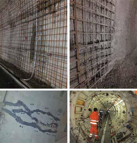
Figure 12.7 Examples of structural improvement works: (a) water collection before concreting; (b) shotcrete re-lining reinforced with steel nets; (c) cracks sealing via resin injections on precast lining segments; (d) mobile formworks for the re-lining of segmental linings. (Courtesy of Geotechnical Design Group srl.)
12.5.2 Design
The design of refurbishment works for old tunnels is a very peculiar topic. The correct development of the design requires the knowledge of all geometrical elements and the current mechanical properties of the lining (masonry, plain and reinforced concrete). Furthermore, a geotechnical model (stratigraphy, physical and mechanical parameters, pore pressures, water table and seepage regime) must be set up.
When a complete and detailed documentation of the tunnel is available, investigations should be devoted essentially to verifying (sample checks) the actual geometry and to evaluating the current mechanical characteristics – strength and stiffness – of the lining. Vice versa, if the documentation is not available, as frequently happens when dealing with old tunnels, surveys are more burdensome and must be extended to the ground surrounding the tunnels, with special care to the entrances. Regarding ground investigations, beyond the usual investigations carried out from the surface, tunnels offer the very advantageous possibility – especially for deep tunnels – of operating from inside, the only downside being the mandatory operational suspension (railway
or hydraulic tunnels) or limitations (roadway tunnels). In any case, the knowledge of the state of stress of the lining, due to the interaction between ground and structure, is extremely relevant because the design of refurbishment works depends very much on it, especially when the demolition of significant parts of the lining is necessary.
Beyond the quality and state of the materials, if the project involves the milling of the lining, it is crucial to obtain a good knowledge of the thickness of the lining; dedicated investigations – direct investigations, if possible – should be carried out along the tunnel to this aim. Furthermore, considering the importance of the lining stress state, numerous flat jack tests should be performed, also taking into consideration the type of soil/rock surrounding the tunnel, the cover and the general state of the lining.
In order to obtain a reliable model, parametric analyses should be carried out to overcome the uncertainties related to: (i) geotechnical operational values of mechanical parameters; (ii) initial state of stress in the ground; and (iii) stress release percentages associated with the excavation techniques. The parametric analyses allow establishing the best set of parameters, capable of reproducing the stresses acting on the lining as close to the measured ones as possible. This calibration of the structural and geotechnical model – which relies on trustworthy measurements of the lining stress state – is crucial to the development of the design of refurbishment works.
Even though complex 3D numerical models can be developed (Galli et al., 2004; de Lillis et al., 2018; Ochma ski et al., 2018), in most cases, 2D models can be effectively used to design the refurbishment works. The stress release technique, either uniform (Karakus, 2007; Möller & Vermeer, 2008) or differential (Altamura et al., 2007), is usually suitable to simulate the excavation. Thanks to the calibration process described above, very simple constitutive laws (linear elastic–perfectly plastic with a tension cutoff for both the soil and the lining) are generally able to provide good enough results. The simulation of the lining using continuous elements (properly taking into account the structural joints) and appropriate meshing makes quite easy the simulation of the milling of the lining, if this activity is foreseen in the design.
Usually, since the uncertainties are relatively few, the design approach adopted for refurbishment projects is deterministic.
In general, it is useful to include in the design a monitoring system tasked with measuring the geo-structural response to refurbishment works through some key parameters. This allows either confirming the design predictions or, vice versa, timely detection of significant departure from the expected behaviour. For instance, when a relevant portion of the existing lining is to be demolished, the strains in the lining or the convergences can be usefully monitored or, if water control works (waterproofing, draining, etc.) are to be performed, measuring the pore pressure around the tunnel can provide meaningful information.
12.6 CONCLUDING REMARKS
The maintenance of tunnels is a very important activity because it allows ensuring good operational performances over time and increasing the life of the structure. The knowledge of the evolution of the state of a tunnel during its entire operational life enables not only to correctly schedule maintenance activities, execute repair works
and put in place protective measures with the aim of minimizing the risks to users, but also to guide the decisions regarding potential use suspensions for safety reasons and, eventually, to carry out relevant refurbishment works.
Since the evolution of the state of the lining and, more in general, of the materials properties is quite difficult to predict as it depends on many natural and anthropic factors, the tunnel should be kept under observation by means of systematic inspections and monitoring activities. Even though modern technologies constantly provide more effective tools, such as laser and thermal scanners or high-resolution images, that also allow minimizing the interference with the tunnel use, visual inspections, carried out by experienced tunnel engineers, cannot be fully replaced by instrumental inspections. Engineering judgement is always essential, especially in tunnelling.
The correct identification of the causes of the damages should always precede remedial actions that should address the causes of the problems whenever possible, rather than simply repair the damages. It is also crucial that the best repair methods and the most suitable materials are selected taking into account the specificity of the site.
The works can be distinguished between ordinary maintenance activities, including minor repairs, and extraordinary refurbishment works. The former, associated with light works, are carried out periodically and are generally local, cheap and fast. Their main aims are to guarantee a safe use, prolong the tunnel life and safeguard the external environment. Protective measures such as steel nets or drainage channels are frequently installed in order to ensure the safety of the users while waiting for more impacting refurbishment works. Refurbishment works deal with the elimination of water inflow and its dangerous effects (water leakage is one of the main causes of concrete degradation) and the improvement in the tunnel lining. Refurbishment works generally involve the entire tunnel and are very costly and time-consuming.
The correct development of the design of refurbishment works requires the knowledge of all geometrical elements and current mechanical properties of the lining. A good geotechnical model is necessary, too. Thus, specific surveys are generally carried out for design purposes, especially in the case of old tunnels, for which information is usually scarcer. The refurbishment design requires models specially calibrated based on the measured state of stress acting on the lining; therefore, these measurements are mandatory. The calibration is crucial because it enables to overcome several uncertainties (geotechnical parameters, stress history and events occurred during the construction) and the shortcomings of the simple constitutive models usually adopted: it is one of the keys of the project success. As for the construction of new tunnels, also for refurbishment works, especially when a relevant portion of the existing lining is foreseen, a monitoring system plays an important role and it is a fundamental part of the design.
AUTHORSHIP CONTRIBUTION STATEMENT
The chapter was developed as follows. Miliziano: chapter coordination. The chapter was joined developed by the authors. All the authors contributed to chapter review. The editing was managed by de Lillis.
REFERENCES
Altamura, G., Burghignoli, A. & Miliziano, S. (2007) Modelling of surface settlements induced by tunnel excavation using the differential stress release technique. Rivista Italiana di Geotecnica, 41(3), 33–47. ANAS (2018) I quaderni tecnici per la salvaguardia delle infrastrutture. Volume IV. Available from: https://www.stradeanas.it/sites/default/files/pdf/1.3.3/Quaderni_tecnici_Volume_4.pdf [accessed 1st March 2021]. Bandini, A., Berry, P. & Boldini, D. (2015) Tunnelling-induced landslides: the Val di Sambro tunnel case study. Engineering Geology, 196, 71–87. CETU, Centre d‘Études des Tunnels (2012) Guide d’application de l’instruction technique pour la surveillance et l’entretien des ouvrages d’art. Fascicule 40: Tunnels. Available from: http:// www.cetu.developpement-durable.gouv.fr/IMG/pdf/Fascicule40-2_cle05a564.pdf [accessed 30th January 2021]. CETU, Centre d‘Études des Tunnels (2015a) Road tunnel civil engineering inspection guide.
Book 1: from disorder to analysis, from analysis to rating. Available from: http://www.cetu. developpement-durable.gouv.fr/IMG/pdf/guide_inspection-book1_hv.pdf [accessed 5th February 2021]. CETU, Centre d‘Études des Tunnels (2015b) Road tunnel civil engineering inspection guide.
Book 2: catalogue of deteriorations. Available from: http://www.cetu.developpement- durable. gouv.fr/IMG/pdf/road_tunnel_inspection_guide_book2_hv.pdf [accessed 5th February 2021]. de Lillis, A., De Gori, V. & Miliziano, S. (2018) Numerical modelling strategy to accurately assess lining stresses in mechanized tunneling. In: Cardoso, S.A., Borges, J.L., Costa, A.P.,
Gomes, T.A., Marques, J.C., and Vieira, S.C. (eds.) Proceedings of the 9th European Conference on Numerical Methods in Geotechnical Engineering, NUMGE 2018, 25–27 June 2018,
Porto, Portugal. London, CRC Press, pp. 1295–1302. Foria, F., Avancini, G., Ferraro, R., Miceli, G. & Peticchia, E. (2019) ARCHITA: an innovative multidimensional mobile mapping system for tunnels and infrastructures. MATEC Web of
Conferences, 295, 01005. EDP Sciences. Galli, G., Grimaldi, A. & Leonardi, A. (2004) Three-dimensional modelling of tunnel excavation and lining. Computers and Geotechnics, 31(3), 171–183. ITA. Working Group on Maintenance and Repair of Underground Structures (1991) Report on the damaging effects of water on tunnels during their working life. Tunnelling and Underground Space Technology, 6(1), 11–76. ITA. Working Group on Maintenance and Repair of Underground Structures (1995) Stateof-the-art of non-destructive testing methods for determining the state of a tunnel lining.
Tunnelling and Underground Space Technology, 10(4), 413–431. ITA. Working Group on Maintenance and Repair of Underground Structures (2001). Study of methods for repair of tunnel linings. Available from: https://about.ita-aites.org/publications/ wg-publications/download/112_ec82e7e2c738b6b06cbc46dfdc409895 [accessed 1st March 2021]. Karakus, M. (2007) Appraising the methods accounting for 3D tunnelling effects in 2D plane strain FE analysis. Tunnelling and Underground Space Technology, 22(1), 47–56. Lunardi, P. (2003) Widening the load at Nazzano. Tunnels & Tunnelling International, 35(7), 16–19. MIT, Ministero delle Infrastrutture e dei Trasporti (2020) Manuale ispezione gallerie (25/05/2020). Möller, S.C. & Vermeer, P.A. (2008) On numerical simulation of tunnel installation. Tunnelling and Underground Space Technology, 23(4), 461–475.
Ochma ski, M., Modoni, G. & Bzówka, J. (2018) Automated numerical modelling for the control of EPB technology. Tunnelling and Underground Space Technology, 75, 117–128. Sétra, Service d’études sur les transports, les routes et leurs aménagements (2010) Instruction technique pour la surveillance et l’entretien des ouvrages d’art. Available from: http://dtrf. cerema.fr/pdf/pj/Dtrf/0005/Dtrf-0005955/DT5955.pdf?openerPage=notice [accessed 30th
January 2021]. Sika (2020) Sika sprayed concrete handbook. Available from: https://www.sika.com/dms/ getdocument.get/664de18e-dbcb-4184-87b7-162e9dd260d5/glo-sprayed-concrete- handbook- 2021.pdf [accessed 8th March 2021].


