60 minute read
AHC fl ywheel solution


While the active heave draw will still be linked to the wave period, Van den Bos points out that the installation would likely have to be sized for the lifting capacity. Therefore, massive crane vessels would likely require a scaled-up version as two cranes working in tandem can have a combined lifting capacity over 14,000 tonnes. Additional flywheels, (rather than a single, oversized mass) make a neater, more flexible package.
Further, Verhoef adds the energy storage capacity can be tailored to suit. If the system is only designed to accommodate the AHC for a few seconds, it could even be installed without the battery, significantly cutting costs.
SPIN
Other developments utilise another aspect of the flywheel principle.
As kinetic energy is proportional to mass times velocity squared, doubling the mass doubles energy storage... but doubling the rotational speed quadruples it. So, increasing the spin speed yields a far more compact unit explains Tim Rumney of Inetic.
Imagine a package “less than a 50cm cube with a mass of around just 100kg”, says Rumney, who was involved in a development project exploring flywheels for naval vessels. He added: “The brief included getting it through any doorway on the ship.”
The focus wasn't so much about regenerating energy, but using the technology for a typical ESS application: peak shaving the onboard load, with motors 'charging up' the flywheel.
The advantages also align neatly with commercial vessels' challenges, especially since, like battery cells, flywheels lend themselves to a modular approach. As a result, “you can pick the amount of energy and power you need and arrange the units in a series or parallel configuration”, Rumney explains, so they can act in concert, or take up the load sequentially.
A typical naval application would see half-a-dozen of these modular packages distributed around the ship, making it suitable for managing “short, but large bursts of power inside a particular area” he says, without recourse to huge capacitors or main grid cabling. Further, this makes it's possible to shunt the energy between nearby consumers - enabling zonal power management.
However, reducing the size in this way requires spinning the flywheel at up to 40,000 or 50,000rpm. Therefore, friction is the enemy: “At that rate, the air drag resistance alone can lose tens of kilowatts of energy if not managed,” explains Rumney. As a result, all high-speed flywheels need to be enclosed in a vacuum.
There's also another challenge for developers: the spin creates a considerable gyroscopic effect. As a ship will experience pitch and roll movement, there's a need for “fairly robust bearings” to deal with these generated forces says Rumney, potentially entailing magnetic or low-friction precision systems, though some recent automotive developments have put gimbals beneath their installations.
CONSTRUCTION IS LIKEWISE EVOLVING.
While steel versions generally tend toward utilising a separate motor to convert spin into electrical energy, others neatly double up the flywheel's role, turning it into a motorgenerator's rotor. These use permanent magnets rather than coil windings for strength and higher power density.
Because a high moment of inertia (that is, mass times radius) is no longer the most important feature at very high rotational speeds - seen in the land based and automotive market units - these flywheels can take advantage of either part or full composite construction, embedding the magnetic material evenly around the perimeter. Balancing these systems is essential; since, as Rumney underlines, “centripetal acceleration at these flywheel speeds can be 10,000G or more”.
Further, fully composite designs can be completely integrated; high tensile strength carbon fibre rotor/flywheel being a single assembly. It's lighter, and, not to put too fine a point on it, potential failures are better contained.
It makes for a much more complex system than the PowerBlade - but getting all these elements right yields a longer energy storage window, with significantly reduced envelope and mass. “Typically this sort of flywheel has an energy storage half-life of several tens of minutes,” explains Rumney: that's a big enough window for a range of 'peaky' consumers.
It might not be long before both types of technology start putting their own spin on short-term regeneration and peak shaving applications.
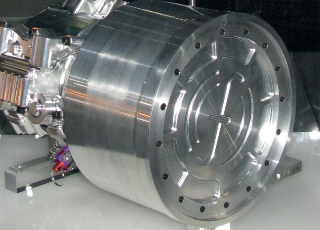
8 High speed
fl ywheels are already fi nding a place in both automotive and landside power industries
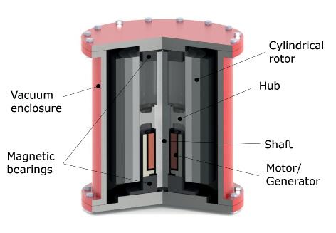
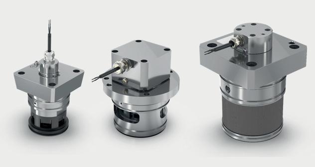
8 The main
components of a high speed fl ywheel
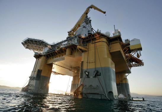
8 The active heave
compensation onboard big drill rigs will add a couple of megawatts to the load on each lift of the string
Photo: NOV
FINLAND LOOKS TO DEVELOP DUAL-FUEL RCCI ENGINE TECH
The upcoming Clean Propulsion Technologies project aims to develop fl exible fuel solutions based on Reactivity Controlled Compression Ignition (RCCI), advanced aftertreatment and hybridization technology for fast and medium-speed combustion engines
The two-year project will give Finland a leading position in low-carbon technology for shipping, off -road vehicles and stationary power applications. It will be led by Maciej Mikulski, Associate Professor of Combustion Engine Technology, and operationally managed by Merja Kangasjärvi, both from Finland’s University of Vaasa. It is expected to commence in Q1 this year if further funding is secured from Business Finland.
The project originates from the CleanShip co-creation project which brought together a consortium of six universities and research organizations (University of Vaasa, Tampere University, Aalto University, Åbo Akademi University, VTT Technical Research Centre of Finland and LappeenrantaLahti University of Technology LUT), nine companies (Wärtsilä Finland, AGCO Power, Dinex Finland, Proventia, Bosch Rexroth, Geyser Batteries, APUGenius, Napa and Meyer Turku) and four international partners.
“The common goal is to secure the global technology leader position for the Finnish powertrain industry by creating a common vision and sustainable business solutions,” says Mikulski. “The reason that marine and off-road propulsion manufacturers can work efficiently together on this project is that both sectors are currently facing dramatic change in tightening GHG and emissions legislation.”
ROADMAP FOR 2030
A technology map has been prepared for technical solutions targeting 2030 emissions goals, and the key research streams are: 5 Develop new intelligent machine learning algorithms for virtual sensors, digital twins and control technologies (for use by the subsequent research streams) 5 By combining engine and after-treatment measures, demonstrate a minimum 20% reduction in GHG emissions and ultra-low NOx and particulate matter emissions 5 Design and implement an optimal control architecture for a hybrid system including batteries which will account for the characteristics of different energy and power sources 5 Build full-scale hybrid demonstrators of propulsion systems, targeting at least a 30% reduction in GHG emissions.
“This project shifts the paradigm from the time and resource consuming incremental improvement method used in earlier projects in favour of fast-tracking completely new systems by the use predictive simulation models,” says Mikulski. “The challenge is the calibration time of the new systems that need to be developed.” To realise the project’s objectives then, physics-based models, 3D CFD simulations and optical engine studies will be used to fast-track the dual-fuel lowtemperature combustion RCCI engine technology which he anticipates will increase engine efficiency by 2% and reduce methane slip by 90% compared to current dual-fuel LNG engine technologies. Further progress towards near zero emissions will be achieved through advanced after-treatment and hybridization technologies developed in the project.
A holistic view of the project’s power train solutions will be complemented by route planning algorithms for operating conditions with large uncertainties, using ship-level simulations for the marine modelling. Together with sustainable fuels, these technologies form a promising short-term solution for decarbonization of energy production and heavy transport while satisfying future emission legislation, says Mikulski.
RCCI RESEARCH
RCCI technology was originally developed at the University of Wisconsin-Madison Engine Research Center laboratories. It is a variant of Homogeneous Charge Compression Ignition (HCCI) that uses in-cylinder fuel blending by first injecting a low reactivity fuel such as natural gas, methanol or hydrogen combined with air and recirculated exhaust gases followed by injection of a high reactivity fuel such as biodiesel directly into the combustion chamber.
Recent research by Mikulski and a team from the University of Vaasa and Lublin University of Technology has led to the development of the concept of using part of the engine cycle to act as a poly-generation reactor altering the reactivity and thermal state of the fuel-air mixture on a cycle-to-cycle basis. The research, published in Applied Energy, indicates that using natural gas as the low reactivity fuel results in high knock-resistance and a reduction in nitrogen oxides emissions, particulate matter and carbon dioxide emissions. However, this leads to relatively low combustion efficiency at low engine loads, causing unacceptable methane slip.
8 Maciej Mikulski,
Associate Professor of Combustion Engine Technology
The researchers used numerical simulations to show that the application of negative valve overlap would resolve the issues by varying the timing and amount of fuel injected directly into the recompressed hot exhaust gases while simultaneously controlling for pressure rise. This on-demand reactivity allowed efficient low-temperature HCCI-like combustion to be maintained across the whole range of engine loads.
Further research showed that two key variables are crucial for closed-loop control: the crank angle of 50% fuel burnt and the combustion duration. These variables are closely coupled and can be calculated in real-time using wellestablished algorithms, making their management feasible.
Almost 99% combustion efficiency and ultra-low methane emissions were achieved under optimal conditions. Net indicated efficiency was 40.5% at 15% load. Low-load net efficiency was 5.5% above the lean strategy baseline and 3% better than the exhaust gas recirculation baseline simulations. The required pressure rise rate control can be achieved by supervisory control despite the negative valve overlap’s substantial pumping losses, and the researchers formulated a workable strategy to manage this based on trade-offs between pressure rise rate and efficiency and emissions.
ADVANCED ENGINE CONTROL
As the research explained the mechanisms of improved combustion efficiency and translated them into control strategies, it bridges the gap between fundamental research on RCCI/HCCI and its industrial application and indicates that the technology can be successfully implemented in next-generation marine and power plant engines to reduce methane slip and sensitivity to fuel quality. The overall concept is based on new, yet proven, engine components, and it accommodates the latest advantages in combustion control, says Mikulski.
Thus, engines operating in RCCI combustion mode will require extensive use of advanced engine hardware such as waste gate - controlled multi-stage turbochargers, fully variable electro-hydraulic valve actuation, exhaust gas recirculation, proportionally controlled charge air coolers and multi-pulse injection capability. “Most of the challenges related to this new combustion system relate to controllability and calibration time,” says Mikulski. “This roughly doubles the number of parameters that need to be controlled independently and calibrated compared to a traditional combustion engine. Model-based development makes this leap possible where incremental development would otherwise make it unobtainable. The development includes cutting edge control protocols necessary for robust RCCI engine operation.”
In the high-speed (off-road) engine domain, two technologies (aside from advanced after-treatment and novel fuels that will also be developed as part of the project) form a short-term solution for reaching ultra-low emissions at superior efficiency, he says. The first is advanced engine hardware like variable valve actuation in combination with cylinder deactivation. This enables efficient engine thermal management to support aftertreatment systems in reaching their peak efficiency. This will be explored experimentally and by simulations.
The second technology is related to advanced engine cycles. “The split cycle engine concept - where separate cylinders realize compression and expand the combusted mixture - is another radical idea offering a step-change efficiency increase combined with higher power density,” says Mikulski.
FUEL CHOICES
Natural gas, biogas methanol will be fuels focused on in the project, along with a biogas/hydrogen mix. “These fuels are considered short-term low carbon transition fuels for shipping instantly reducing engine-out CO2 emissions by approximately 25%,” Mikulski says. “For both fuels, (L)NG and methanol, the worldwide bunkering infra is already majorly developed and IMO Stage II/ III engine technology is already there. Energy density satisfies the need of long-haul sea transport, and both fuels have similar, efficient routes towards full sustainability with CO2 capture/hydrogen synthesis and already now biogas and hydrogen can be, and are, added to natural gas to make it more sustainable. The use of (L)NG, in particular, is expected to scale up rapidly in the marine domain - we thus need future proof solutions to support this transition.”
FUTURE CHALLENGES
The use of 100% hydrogen will be considered. The Clean Propulsion Technologies project will build a high-speed offroad demonstrator engine for this, while another project the University of Vaasa is leading, CHEK, will scale it up for use in the marine domain. “The technological readiness of the 100% hydrogen solution in the Clean Propulsion Technologies will be rather low. We will show that we can do it, yet without particular targets in terms of emission conformity and efficiency, the initial-step ambition, in our opinion, fits into the current infrastructural maturity of the 100% hydrogen as fuel concept.”
While the roadmap for the project is developed for 2030, there is still uncertainty beyond that, and therefore more mapping work required once the project focuses on 2050 emissions reduction targets. According to Mikulski, the current energy transition is a big challenge, but also a big opportunity for further research. “To meet the challenge and seize the opportunity, broad community support is necessary, and various stakeholders need to start working together on a common and unbiased vision. In Finland we have taken an important step towards this success.”
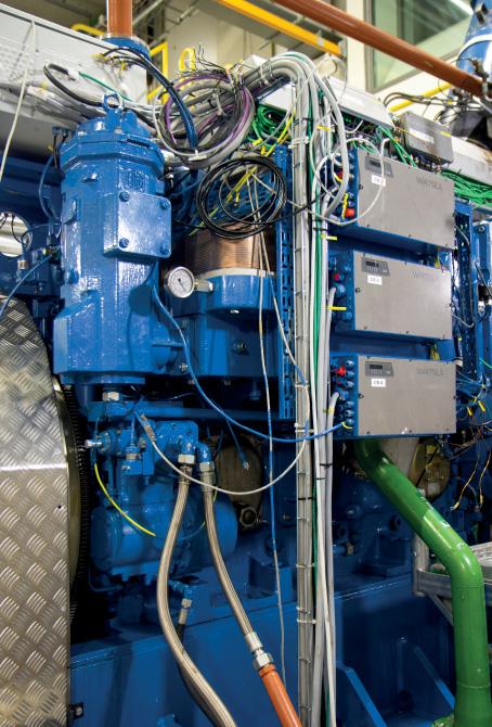
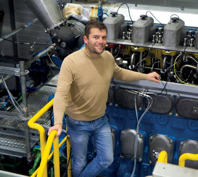
Credit: Riikka Kalmi, University of Vaasa 8 A Wärtsilä test
engine at the University of Vaasa VEBIC energy lab
SOGAVS MEET THE MULTIFACETED CHALLENGES OF CHANGE
With new developments come challenges for tried-and-trusted components. Rick Boom of Woodward talks to Stevie Knight
Woodward’s solenoid-operated gas admission valves (SOGAV) are the well-established ‘go-to’ for the industry, but they’ve recently had to adapt to new realities.
To return to basics for a moment, these SOGAVs are a family of electrically actuated, fast-response gas valves for port fuel admission on four-cycle, turbocharged natural gas or dual-fuel engines. They work by pressure loading the metering plate to the ‘closed’ position; it’s opened on demand by the valve’s ecore solenoid, which has a short travel and high output-force designed to deliver consistent and precise cylinder-to-cylinder control.
It’s a rather elegant design suited to a broad swath of applications: that’s the reason they’ve been so successful in the past, and why they’re in the frame for the gaseous fuels of the future, Rick Boom of Woodward tells MS.
But getting everything lined up for the new fuels is by no means straightforward.
While the IGF-Code came into force in 2017, frankly “the industry as a whole was just not ready at that moment”, admits Boom. It was especially challenging for the SOGAV design, sitting in the critical ‘Zone 0’ as described by the IGF Code - right inside the gas flow.
Part of the issue was technical: while the code sets the goals for the safety levels required for compliance, it leans heavily on the international IECEx 60079 (explosive atmospheres) standard: this details “the ‘how’ and ‘what’,” he explains.
However, this standard is primarily designed from a pure explosion risk perspective: according to Boom, creating a marine gas admission valve product that fulfilled the sometimes conflicting criteria pushed the team into “largely unexplored” territory.
Take apparently simple items such as cable glands or solenoid encapsulation materials: these have to be both compatible with CH4 and also cope with the heat and vibration that comes with the SOGAV’s position right on top the cylinders. “There were products that looked good on paper but couldn’t survive this environment,” he says, “some of them failing within minutes of initiating a test”.
Further, just occasionally a suitable alternative couldn’t be found, which meant going right back to the drawing board and devising a solution that could sit within the boundaries of both the IECEx requirement and IGF code.
Moreover, not many ‘notified bodies’, (that is, those able to award the necessary listing) had any familiarity with marine
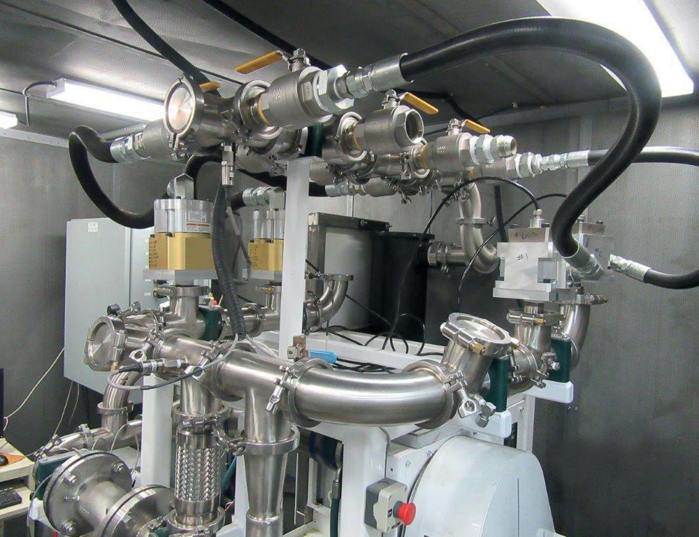
8 New fuels
have called for a lengthy research and development process: Woodward’s SOGAV250 and SOGAV65 on the testbench
engine room conditions. “So, finding one that was able to help us work out a solution was quite a challenge,” he admits.
Material compatibility wasn’t the end of the issue: there were also design conflicts.
For example, Woodward’s SOGAVs have integrated leak detection: this has been developed to address safety concerns around low-flashpoint fuels - but it relies on being accessible from the surface of the double-walled piping. That didn’t sit well with the IECEx requirement which wants the whole thing completely isolated; the notified body wanted the leak detection functionality entirely removed. “Class - well, they weren’t happy,” says Boom. It was eventually sorted out, but it took work.
And at this point, others stakeholders come into the mix. Resolving such conflicts might be relatively easy if there’s an unlimited palette of optional extras, but that just not going to wash with the OEMs: their requirement is for valves that sit in the same space, with the same characteristics as before. In short, “neither OEM customers nor class societies wanted to make alterations to proven designs or features”, says Boom: “They want a tested, fit and functional product”.
So, compliance been a lengthy business, “taking many sessions with OEMs, Notified Bodies, CIMAC and IACS before we even settled on the specification and started the design work”, but the concerted effort has paid off.
It’s not the end of the evolution for either the IGF-Code or Woodward. In fact, a recently emerging fuel has caught the SOGAV team’s attention.
Ammonia appears to be breaking ahead of the pack because it has better energy density than many of its competitors, and it promises a route forward into power-to-X fuels: “You hear about ammonia almost daily,” says Boom, pointing out that big players, including Maersk, have been paving the way for take-up. It’s not the only candidate by a long chalk, but “low-pressure ammonia gas admission is a realistic option,” he says, “and we have to make it work”.
Like others, ammonia will need to be embraced by the IGF Code to become a useful alternative. As such, it has many of the same considerations at other low-flashpoint fuels, explains Boom, who happens to be one of the code’s original architects.
Interestingly, ammonia - NH3 - and natural gas (largely CH4) belong in the same group as far as their flashpoint is concerned, and while combustion characteristics diverge there are useful potential mixes and possibilities for dual-fuel technology crossovers.
But once again, there are further demands which don’t sit easily with each other, planting manufacturers like Woodward squarely between conflicting requirements.
Things start to get tricky because SOGAVs need to retain their safety within the aggressively corrosive (and toxic) ammonic atmosphere.
“We’ve had to identify potential weaknesses for ammonia operation, and replace them - especially the elastomers,” says Boom. However, the first problem has been sourcing the alternatives and sadly, there’s been “a fair amount of disappointment” along the way, he adds - though the team have won through before, so he’s confident they will do so again.
INSIDE INFORMATION
Alternative fuels aren’t the only spur to innovation.
“Our SOGAVs do have a good track record. But there’s a growing focus on things like carbon emissions and methane slip, and this translates into heightened accuracy, a tightening of the mechanical tolerances,” says Boom: that, in turn, can drive up costs. However, he explains another, effective method to help mitigate these growing requirements’ impact is to apply a diagnostic system and electronic support.
That means getting inside information on the operation. The ECU triggers the mechanism on demand, but there’s been no feedback to precisely ascertain how it responds. So, recent developments have added current profile monitoring, which plots exactly when the valve opens and closes.
“A drift in performance - usually from wear and tear - can usually be compensated by control algorithms,” says Boom. The new diagnostic element also allows an accurate prediction of the remaining time before it has to be replaced entirely. While these SOGAVs are built for a typical 16,000-24,000 hour life, he comments that “it’s very useful for the operator to know if the valves are good for the next 5,000 hours”.
Finally, Woodward’s SOGAVs are almost ubiquitous but this can be a double-edged sword. As a result of the valve’s market penetration, “we are dealing with every OEM and every engine, each of which has its specific validation requirements”, he explains, adding: “We are steadily working our way through them all.”
It’s obviously a protracted, detailed business. However, these adaptations already cover around 99% of all applicable engines between a 17cm and 54cm bore size - so it’s pretty sure they will be ready to meet the new demands.
Will there now be a pause for breath in the round of modifications? Possibly not - partly because the industry shows no sign of settling the fuel contest anytime soon: in fact, it might be just beginning, predicts Boom: “The whole journey toward zero emissions is leading a lot of R&D... there’s a high number of combustion recipes and potential systems, which will have to boil down over time.” This, of course, impacts both material and electronic development of a range of components.
However, “the SOGAVs’ longevity stems from the company’s efforts to meet the needs of the market”, he concludes. “We’re always innovating.”
The new diagnostic element also allows an accurate prediction of the remaining time ‘‘ before it has to be replaced entirely. While these SOGAVs are built for a typical 16,000-24,000 hour life, it’s very useful for the operator to know if the valves are good for the next 5,000 hour
8 Fulfi lling
confl icting criteria: Woodward’s revisions of marine SOGAV products entails satisfying stakeholders and design issues as well as material compatibility
NO WINNER YET IN QUEST TO UP BATTERY ENERGY DENSITY
Many start-ups have announced developments in lithium-ion battery technology, but, says Dr George Crabtree, Director of the Joint Center for Energy Storage Research (JCESR) at Argonne National Laboratory, “I’d like to see a little more before putting my money on the table.”
It takes fi ve years in the laboratory to prove that you really have a solution, he says. It takes another three to fi ve years to reach commercial scale. And, in the quest for higher energy density in lithium-ion batteries, there’s one problem that scientists have been trying to solve for over 50 years.
The anode is made up of layered graphite layers, and the lithium is loaded (intercalates) between the layers. The maximum is one lithium for every six carbons, so only one seventh of the atoms are storing and releasing energy, and the graphite takes up a lot of space. One potential solution is to use pure lithium metal as an anode. This would increase energy density by a factor of 10. The trouble is that, over time, the lithium forms dendrites through the electrolyte that eventually reach the cathode and short out the battery. A solution is being hotly pursued, says Crabtree, but not a lot of information has been made public by the start-ups involved.
An alternative is to use silicon in combination with graphite. Silicon intercalates lithium at a higher rate: four lithium atoms for every silicon atom. The catch is that in doing this, the silicon expands to about four times its volume. Eventually it cracks and starts to react with the electrolyte - a showstopper. Using silicon nanoparticles prevents the cracking, but it eventually loses reactivity anyway. “So nowadays, probably every commercial lithium-ion battery has maybe three, four or five percent silicon. Even a small increase in energy density is really valuable.” There are start-ups that say they can reach 50%, but a time scale for commercialisation is very “drafty,” says Crabtree.
Another potential way of increasing energy density is to change the electrolyte to a solid rather than the organic liquid typically used today. This removes the risk of thermal runaway if the liquid electrolyte reaches 150oC. However, many of the solid state electrolytes are polycrystalline with lots of crystal grains jumbled together which are vulnerable to dendrite formation. There are start-ups claiming developments with glassy solids, so it’s a solution that is on the horizon, says Crabtree.
“The big problem with solid state electrolytes is that lithium doesn’t move very fast in solid materials of any kind. It moves much faster in liquids,” he says. “It turns out there are a couple of families of solid state electrolytes where y lithium does move about as fast, even maybe a little bit faster, in the solid as it does in the liquid electrolytes, and those are the ones that are being looked at. Most of these have five or six elements in them. So, there’s a lot of opportunity to tweak the composition and try to get the best conductivity.”
An alternative is to use an aqueous electrolyte. The problem with water is that it electrolyses at very low voltage. “You can pull some tricks and maybe get the operating voltage up to two volts, but not any d as it does in the those are the ked at. Most of ements in them. rtunity to tweak to get the best use an aqueous m with water is ery low ome e

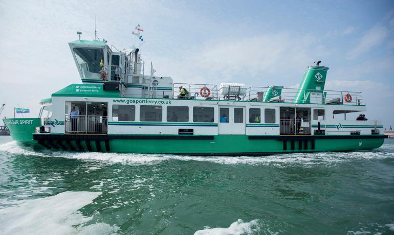
8 As part of the
FLO-MAR project, the operation of a a Gosport ferry in the UK using a fl ow battery was simulated
8 George Crabtree
is an Argonne Distinguished Fellow and the Director of the Joint Center for Energy Storage Research
higher. And the lithium-ion batteries that we have now operate at 4.3 volts because the organic electrolyte is more stable.” If the lithium ions are dissolved at very high concentrations in water, it is possible to get up to three volts and avoid the potential for thermal runaway, but this still doesn’t match current technology. It does lead, though, to the proposition that very high concentrations in organic electrolytes might also increase voltage, and this is being researched at present. Crabtree notes that using water as the electrolyte or using a solid state electrolyte means that existing anode and cathode technology could remain much the same as it is now.
Another approach to improving energy density is to change cathode technology. The original cathode developed by Sony in 1991 was cobalt dioxide. Cobalt is expensive, and the majority of global supply comes from mining operations in the DRC (formerly Zaire), which has a 60% market share. As an alternative, equal amounts of manganese, nickel and cobalt have been used (NMC technology). Today, a ratio of 8:1:1 is becoming standard. The more nickel that is used, the higher the energy density. However, nickel is more unstable which can affect battery lifetime.
Crabtree says that for heavy transport covering long distances, an energy density of around 800Wh/h per kilogram is needed. Lithium-ion is about 275. “And no matter what you’re doing with lithium-ion, it’s not going to get to 800. That’s where you need something like lithium-oxygen or perhaps lithium-sulphur technology.”
Multivalent ion technology is another alternative. Metals such as magnesium and calcium give up two electrons rather than one, giving twice the energy density of lithium. Magnesium doesn’t form dendrites as rapidly as lithium, and being less reactive means it poses less of a fire risk. The problem is that none of the cathodes that work for lithium work for magnesium. “You’re still faced with finding an electrolyte and a cathode that ideally you could intercalate the magnesium in. There are several electrolytes that work with the magnesium anode, but they are not the ones that work with the cathode.” This is just one of the many areas of research that JCESR is currently engaged in.
ADVANCING LFP TECHNOLOGY
Lithium, nickel and cobalt demand could rise 20-fold by 2050, driving a chemistry change that Lithium Australia subsidiary, VSPC, believes has the potential to make Australia a battery manufacturing hub.
Australia is already the world’s leading producer of lithium, and VSPC manufactures high-quality lithium-ion cathode powders, including lithium ferro phosphate (LFP). The market for LFP technology is expected to grow five-fold by 2030 as a result of its advantages over lithium nickel cobalt manganese (NCM) and lithium nickel cobalt aluminium (NCA) technologies. Already widely available, LFP batteries offer superior thermal stability, longer life, wide operating temperature range and lower cost. Additionally, they contain less lithium, no nickel and no cobalt.
Currently, around 98% of all LFP cathode powders are produced and used in China, but Adrian Griffin, Managing Director of Lithium Australia, says LFP is likely to be the dominant chemistry globally within a few years. He says his company is ideally situated to meet the expected increase in demand from Europe, India and North America which is being driven by electric vehicle, renewable power and 5G communication applications, with marine applications also anticipated to increase.
“Over the last 12 months, global demand for LFP has increased over 25%, bringing Chinese LFP cathode powder manufacturing up to over 100,000 tonnes per annum,” he says. VSPC is positioning itself as a major alternative supplier through the development of patented optimised acid digestion production methods that reduce chemical costs by up to 10%. “The ability to utilise low-cost feed materials for the production of LFP batteries puts Australia one step closer to becoming a competitive location for battery production,” says Griffin.
The main drawback of LFP is that its energy density is lower than other lithium-ion technologies, but the situation has been improved through more efficient cell geometry and through the addition of manganese (LMFP). As well as reducing the cost of manufacturing powders, VSPC has now also successfully produced LMFP battery cells which have up to 25% higher density than LFP cells due to their higher voltage. The technologies are currently being scaled up.
VSPC is also working on a new generation of rapid charge batteries based on the “olivine” crystal structure that gives LFP many of its superior properties including unparalleled safety. With so much capital invested in lithium technology, Griffin says it will remain dominant in the market for at least the next 10 years despite the emergence of other chemistries and technologies such as vanadium flow batteries.

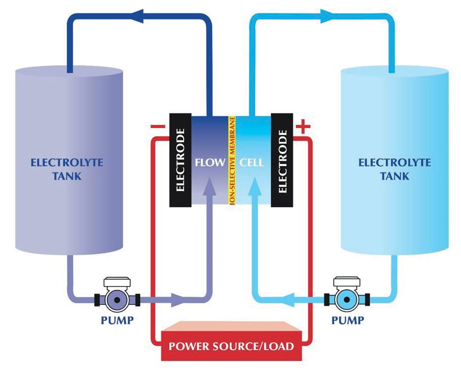
FLOW BATTERY ADVANTAGES
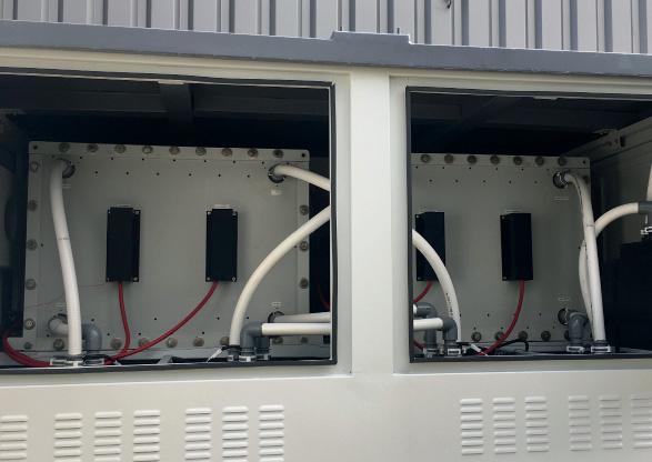
Flow batteries have electrolyte liquids stored in separate storage tanks, not in the power cell of the battery system. During operation, the electrolytes are pumped through the stack of power cells to produce electricity.
The theoretical redesign of a small diesel-powered ferry undertaken delivered unexpected results to the project partners involved in FLO-MAR, a UK-government and
8 A fl ow battery
generates electricity by pumping electrolytes through the stack of power cells
8 Far left: Narve
Mjøs, Director Battery Services & Projects at DNV GL and Henrik Helgesen, Senior Environmental Consultant at DNV GL
industry funded project to develop flow batteries for marine applications. Naval architects Houlder, energy storage specialists Swanbarton and classification society Lloyd’s Register, brought together by innovation cluster Marine South East (MSE), found that not only did replacing the diesel electric propulsion system with a flow battery save space, it also improved operational performance.
“Flow batteries don’t have particularly good energy density, so we’d expected the massive battery would reduce the payload of the vessel. This was not the case,” said Dr Jonathan Williams, CEO of MSE. The original ferry design had a large bunker tank so the vessel only needed to be taken off-duty to bunker once a week. For the flow battery variant, it is charged at berth overnight by pumping out the electrolyte and replacing it, so the electrolyte tanks could be smaller. The battery stack fitted into a void space, and smaller ballast tanks could be used because there was no diesel consumed and subsequent ballasting required.
The FLO-MAR project partners anticipate the technology will be well suited to a variety of vessels including domestic passenger vessels, work boats and wind farm vessels, and coupled with renewable energy and a containerised battery, such as that being trialled by MSE at the Port of Portsmouth, port bunkering infrastructure can be kept to a minimum.
Williams notes that the risk of thermal runaway with lithium-ion technology can mean that these batteries need to be located above deck, “not an ideal position for putting 100 tons of batteries. It obviously affects stability and can get in the way of operations.” Flow batteries are not susceptible to thermal runaway, so they don’t require the same level of ambient temperature control, and unlike lithium-ion batteries they don’t need to be replaced in 10 years’ time - something that can involve a major drydock refit.
Energy capacity can be scaled in a flow battery by adding more electrolyte. “With a lithium-ion battery, you basically get the package, and it has a certain discharge rate (C-rate), which varies a little bit, but it’s not very adjustable. So, you often end up putting in more batteries than you really need, because you either need to have very high power or you need very high endurance. With a flow battery you can adjust those two parameters independently, so you’ve got more design flexibility.”
The project partners have plans for installing a demonstration flow battery in a small harbour maintenance vessel, and a barge project is anticipated. At this stage, Williams says the choice of electrolyte is still uncertain. Vanadium flow batteries are the current technology, but organic, non-toxic electrolytes are being evaluated with the University of Southampton.
QUEST FOR ORGANIC ELECTROLYTES
The quest for higher energy density using organic electrolytes for flow batteries is also being taken up by the SONAR Project led by Professor Jens Noack of the Fraunhofer Institute for Chemical Technology ICT, in Germany. In this case, the search is focused on flow batteries for stationary, renewable energy power storage which would take advantage of the technology’s ability to store energy for longer than the four to eight hours achieved with lithium-ion batteries. SONAR will integrate models from the atomistic scale up to the battery stack, and use techniques such as machine learning to evaluate different prospective materials.
Noack notes that the search for alternatives to vanadium or iron flow batteries is particularly relevant in Europe, as the continent doesn’t have any vanadium resources or indeed many inorganic minerals. “In organic chemistry, there are millions or even billions of possible candidates for active materials,” he says.
ALL FUELS ARE DANGEROUS
Asked if the potential for thermal runaway was enough of a safety risk to move away from lithium-ion batteries, Narve Mjøs, Director Battery Services & Projects at DNV GL, says all fuels can be dangerous if not managed carefully. “Even fossil fuels are very dangerous with an enormous energy density. It’s important then to handle with care. We see better battery products today compared to yesterday. There are better safety rules based on new research and also more experience.” However, batteries that offer a high degree of safety, in some cases compromise on energy density and lifetime of the battery, he says. “We think that lithium-ion will still be the dominant technology in the near future, since it offers a reasonable compromise between safety, energy density, lifetime and costs.”
Mjøs says costs are coming down all the time, and all ships may have a large or small battery in the future. He notes an operational advantage: “You really have power when you need it. The acceleration is much higher than with, for instance, a traditional engine.”
THE FUTURE BATTERY MIX
Henrik Helgesen, Senior Environmental Consultant at DNV GL, anticipates that solid state lithium technology and lithium sulphur batteries will be introduced in around 3-5 years. It is very uncertain whether technologies like lithium air batteries will be commercialized at all, even when it has the largest theoretical energy density. The end result will be a mix of different types of batteries with different energy densities “depending on how much you want to pay.”
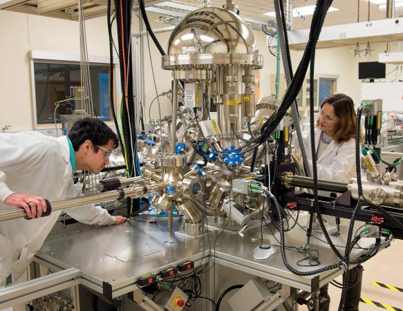
8 The Electrochemical
Discovery Laboratory at Argonne National Laboratory

8 An Argonne
National Laboratory researcher testing an electrochemical cycling performance at ANL’s Battery Laboratory
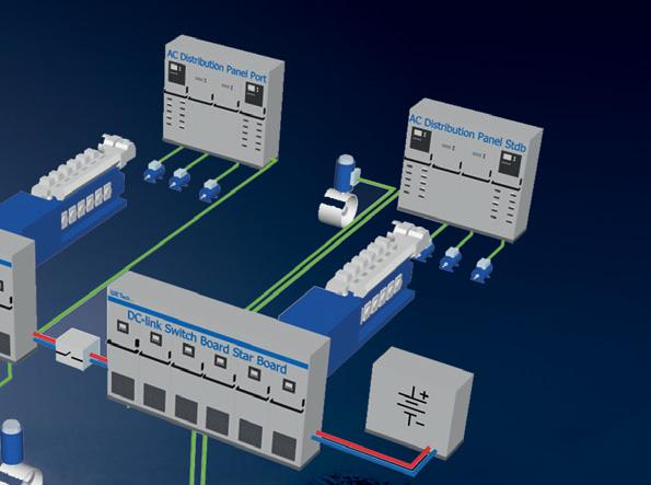
CORVUS TO DEVELOP PEM FC SYSTEMS WITH TOYOTA STACKS
Toyota and Corvus Energy have announced plans to develop hydrogen fuel-cell systems, with the intention of making maritime-certifi ed fuel cell systems commercially available by 2024
The development project has received €5.2m in funding from state agency Innovation Norway, and also includes energy major Equinor, shipowners Norled and Wilhelmsen, ship design company LMG Marin, the NCE Maritime CleanTech cluster and R&D institution the University of South-Eastern Norway (USN).
Many of the project collaborators are also participating in the Topeka PEMFC-powered Ro-Ro demonstration project, as part of a wider Norwegian project to develop hydrogen supply chains along the Norwegian coast.
“Adding fuel-cell modules to our product portfolio is a natural step for Corvus and advances our vision to be the leading supplier of zero-emission marine solutions. Fuel-cell technology has reached a maturity level where scale-up of systems will be the next step. Toyota is in the forefront of the development and is by far the best partner for us to make this a success,” said Corvus Energy CEO Geir Bjørkeli.
LT PEMFC SYSTEM
The development project’s first target is install a LT PEMFC marine fuel-cell system onboard a vessel in 2023. This is intended to be succeeded by the delivery of a first Corvus type-approved PEM fuel cell system by 2024.
Corvus intends to follow a modular approach, developing a scalable product that can be produced in large volumes, in its fuel cell development.
“We will ensure that the first system solution provided in this partnership will be scalable for vessels requiring everything from 200-300kW to 10,000+ kW of installed power,” Corvus’ Project Director, Kristian Holmefjord told The Motorship.
Toyota will supply both the individual LT PEM fuel cells, and the LT PEM fuel cell stacks, along with the fuel cell controls as a modular solution. Corvus will supply a fuel cell system to operators, including a unified marine control system covering both battery and fuel-cell operation.
Corvus is also identifying alternative solutions, as there is no “one size/type/FC-chemistry fits all” for marine and other fuel cell solutions might be better suited to larger vessel requirements.
The company already has an objective to develop a second fuel cell system solution, drawing on alternative Solid Oxide Fuel Cell (SOFC) or High Temperature PEM FC technologies by 2025.
The SOFC technology offers opportunities in the deep-sea market, as the fuel cell can operate on lower-purity hydrogen or other fuels, such as ammonia or LNG, unlike Toyota’s LT PEMFC technology. “The space requirements of hydrogen storage aboard deep-sea vessels remain an obstacle to the use of compressed hydrogen at present,” Bjørkeli commented.
FC SYSTEM ASSEMBLY HUB
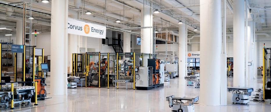
As part of the announcement, Corvus confirmed that it plans to establish a production hub producing commercial marine LT PEM fuel cell systems at scale in Bergen.
The production centre will be eventually oriented towards both the export and domestic Norwegian markets although initial demand is expected to come from the domestic Norwegian market.
“As fuel-cell technology has reached a maturity level where the scaling-up of systems will be the next step, a key advantage to partnering with Toyota was the ability to move straight to industrial production to scale up,” said Corvus Energy CEO Geir Bjørkeli. “Toyota is at the forefront of the development and is by far the best partner for us to make this a success,” Geir Bjørkeli added.
While Toyota has a comparatively short history in the marine market, and only announced plans to develop fuel cells for marine applications in 2020, it has a long track record in developing fuel cells for the passenger vehicle market. It is also the largest manufacturer of LT PEM fuel cells in the world, in what remains a comparatively small market. Sales of hydrogen fuel cell vehicles (FCEV) in 2020 were below 10,000 units globally.
The ramp up of production of Toyota’s LT PEMFC stacks at
8 Corvus Energy’s factory in Bergen
Toyota’s manufacturing site in Honsha in Toyota City in Japan from 3,000 units to 30,000 units per year, was also expected to lead to significant economies of scale.
Toyota launched a second generation of its LT PEMFC stack technology for the Mirai hydrogen fuel cell passenger automobile in Japan in December 2020. Compared with the preceding generation of LT PEMFC stack, the Gen 2 stack achieved weight savings, production cost efficiencies and also increased power density, Freddy Bergsma, Senior Manager Strategy and Business Development, Fuel Cell Business Group, Toyota Motor Europe confirmed.
Concurrently, further advances in LT PEMFC technology were planned, which were likely to build on recent improvements. Plans to develop a Gen 3 stack were already underway.
In other words, the agreement secures Corvus access to proven fuel-cell technology while enabling large-scale production and competitive pricing, Corvus CCO Halvard Hauso said.
NEW BUSINESS UNIT FOR CORVUS ENERGY
As part of the project, Corvus is intending to develop a world leading maritime fuel cell centre in Bergen. Corvus Energy’s Project Director, Kristian Holmefjord, told The Motorship that the initial team will number about 20 dedicated roles, while drawing on the company’s engineering expertise from its R&D facilities in Porsgrunn, Norway and Vancouver, Canada.
One of the key aspects of the project will be to develop a series of optimised solutions for customers, drawing on Corvus’ extensive experience of the operation of battery systems aboard vessels, as well as Toyota Motor Europe’s insight into the PEM FC modules.
“The optimisation here is crucial and a big differentiator in the market. We will strive to make the best solution for our customers, not strive to only supply batteries or only supply fuel cells,” Holmefjord said.
Finally, Holmefjord added that Corvus did not have any plans to enter the hydrogen storage system production or delivery space, or to become involved in compressed or liquid hydrogen (LH2) production or supply chains.
The Motorship notes other companies within the development consortium have expertise in those areas: Equinor is currently developing a LH2 production facility at Mongstad near Bergen, while Norled and LMG Marin are participating in a project to develop an LH2-fuelled ferry.

8 Corvus Energy
CEO Geir Bjørkeli: ”a key advantage to partnering with Toyota was the ability to move straight to industrial production to scale up”


CINDERELLA ‘SHOE’ THAT TURNS A TUG INTO AN ICEBREAKER
Icebreakers are big, expensive beasts but they can be lazy, “sometimes only working three or four months of the year”, says Jyrki Lehtonen of ILS Ship Design & Engineering. It’s left people wondering if there’s not a more cost-eff ective answer
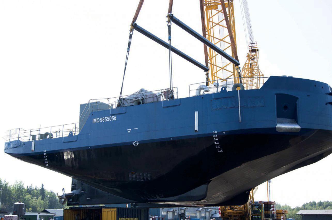
Image: ILS
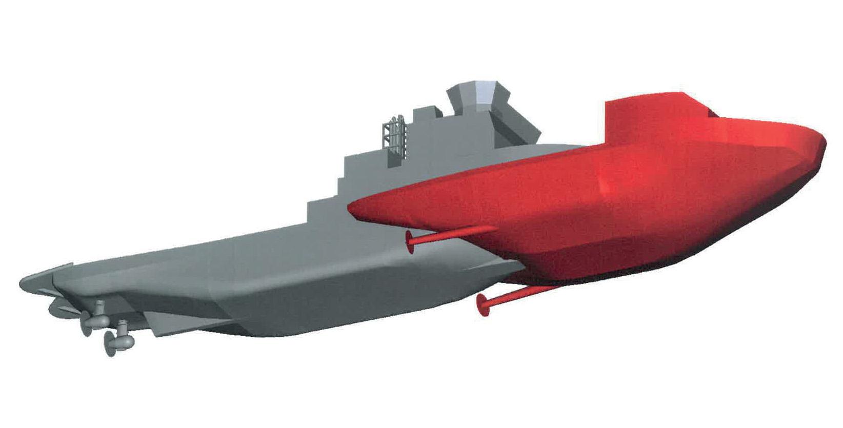
And now there is. It’s a rather surprising alternative from ILS: a removable bow which, when fi tted to a suitably robust vessel such as an ice-class pusher tug, allows it to take on icebreaking duties. In summer the bow can simply be unpinned, leaving the tug to return to more typical operations.
The design itself is reminiscent of a horseshoe (albeit with hefty bracing connecting the two sides) that fits quite snugly around the vessel’s form, conferring both strength and extra forward height.
However, it was clear the addition also needed to bring substantial power along with it. Thus, the self-propelled removable ice breaking bow (SRIB) was born: Lehtonen explains it’s almost a complete vessel in its own right, with engines, ballasting unit, and full automation.
Interestingly, the very first of them is already out there and working the waterways around Lake Saimaa. This is a somewhat smaller 25.3m version with a 12.5m beam and designed for inland operation: paired with its ‘other half’ - a tug called Calypso - the combined length comes to around 40m, with a total installed engine power of 2.6MW.
Hooking up was another challenge: it was necessary to create a single, rock-solid unit from the two halves and moreover, achieve it “inside a working day” says Lehtonen.
The solution, a three-point connection developed by partner ACM Trading, is a sophisticated ATB crossover with a central solid steel pin and sleeve amidships, plus hydraulically operated pins on the port and starboard wings. Interestingly, this allows the mating to be accomplished well within the timescale: if the trim and draft need attention in order to match up with the tug, the onboard ballasting system of the SRIB will compensate, possibly taking a couple of hours. If that isn’t necessary, he explains “the connection can be as fast as 10 minutes”.
FULL-SCALE
However, while the ‘pint-size’ version is operating successfully, the larger, Baltic-capable SRIB is a significant step up in scale. The first of these designs will likely have a waterline breadth of around 24m, and the length, when united, could easily double that of the pusher tug alone.
The idea is that taken together, the ice strengthened removable bow and the total power combination will yield capabilities “corresponding to those of present Baltic icebreakers,” he explains. Therefore, the duo should be able to achieve a 6kn progress in 0.8m level ice - a speed high enough for escort duties.
As a result, the combined pusher and SRIB will likely require a total installed power around the 11MW mark.
There are some givens. The candidate vessels will
8 Ship Design & Engineering’s removable bow fi tted to suitable pusher tug would allow it to take on icebreaking duties
8 Slipping into the
icebreaking bow
necessarily be of 1A Super ice class notation, and it’s most effective if “the bow and tug divide the power about fifty-fifty”, says Lehtonen: therefore the vessel will ideally already have 5MW or so of installed power - though there’s some flexibility. The balance may develop differently for the full-scale builds, depending on the pusher and local characteristics: “Each case will need a separate design,” he adds.
Like its smaller sister, the first of these larger SRIBs will likely incorporate diesel generators inside the hull - although battery power systems are under consideration for the future, it will require further development.
There are a number of elements governing the choices, says Erno Tenhunen of Danfoss Editron, the company supplying the power and distribution for the inland SRIB. For example, a DC bus gets rid of the need for AC/DC converters and so on, and it also allows the gensets to run at variable speeds. both absorb and release large amounts of power pretty much instantly, without degradation.
However, the 10.4F/650V DC/DC converter-controlled supercapacitor onboard the inland SRIB, developed by Danfoss itself, has a sizeable (for a supercap) 3.1MJ/ 0.86kWh energy density in order to cover blackout and spinning reserve. But the choice of ESS answers another concern: the cold.
Unlike batteries which usually start failing below 20degC - and which can be impaired by low-temperature recharging - supercapacitors will continue working happily even when deep into sub-zero conditions. It also helps that they can be designed to meet very high shock and vibration requirements: icebreaking can be a jarring business.
Lastly, Tenhunen points out the SRIB necessarily relies on “a highly automated power system”, with the control interface located inside the pusher tug’s wheelhouse.
VARIATIONS
It’s worth noting the design embraces a number of alternatives. To start with, the straightforward scaled-up version of the inland SRIB has two, aft-facing, 3MW fixed pitch reaming propellers in skegs on both sides of the horseshoe.
But double-acting icebreakers have a hull optimised for running ahead in open waters and thin ice, turning around and proceeding astern to take on thicker chunks: this allows the propellers to bite into the ice and flush it aft very effectively.
Therefore other solutions on ILS’ drawing board lean further toward this kind of operation. One of the designs positions a 6MW, fully azimuthing ‘pulling’ pod at the bow: another places a pair of smaller, similarly oriented 3MW units on each side, and there is a fourth version which extends the two, straight shaft lines and propellers forward. Further, Lehtonen explains these are just the base designs: it’s possible to incorporate more pods or propellers to adapt to different challenges.
Moreover, some of these options - such as the single pod - can reduce the beam, tailoring the SRIB to narrower approaches: therefore the signature horseshoe shape could be swapped for something closer to a slipper.
Finally, how does the bottom line add up?
The main costs accrue from the installed power level, says Lehtonen. But, he points out, it’s much cheaper than building an entire vessel: there’s no bridge or associated kit, and likewise, no accommodation or crew facilities, “so the bow doesn’t come to more than 30% of the cost of buying a complete icebreaker”.
It’s already gaining interest, and there appear to be contracts waiting in the wings. Certainly the SRIB looks like becoming a cost-effective choice for regularly ice-bound, industrial locations, making them navigable year-round.
It might not be that long before more pusher tugs find an alternative winter identity by slipping their bow into an icebreaking ‘shoe’.
Unlike batteries which usually start failing below 20degC - and which can be ‘‘ impaired by low-temperature recharging - supercapacitors will continue working happily even when deep into sub-zero conditions. It also helps that they can be designed to meet very high shock and vibration requirements: icebreaking can be a jarring business
The permanent magnet motors on each shaft line are also very compact, as are the DC/DC inverters which, usefully, don’t require locating in an isolated area: as a result they can be positioned directly inside the machinery space. Further, while it’s plausible that the 6MW or so of power for the fullsize SRIB could still be supplied by two generators, efficiency might best be served by divvying up demand between four of them.
But most importantly, icebreaking operations have a very high, rapid power demand. In order to avoid over-sizing the generators an energy storage unit will peak shave these spikes, as well as enabling open water transits on just one genset. Significantly, it’s not a battery: it’s a supercapacitor.
Although batteries can hold a charge for much longer, supercapacitors are far superior when it comes to sheer power output as they store energy in a static electric field rather than electrochemically. As a result they are able to
RICARDO INVESTS IN UK HYDROGEN RESEARCH CENTRE
As Ricardo expands its research into hydrogen storage and fuel cells, effi ciency and operating costs give FCs an edge over internal combustion engines, Ricardo’s experts tell Paul Gunton
Fuel cells are likely to prevail over internal combustion engines (ICEs) in the long-term quest for carbon-free marine propulsion, believes Andrea Trevisan, chief engineer at the UK-based engineering consultant, Ricardo.
It is exploring the potential of hydrogen and ammonia as zero-carbon fuels for both ICEs and fuel cells and Mr Trevisan told The Motorship that fuel cells’ dominance will be because they are more efficient than ICEs, making them cheaper to run. ICEs, meanwhile, will provide an “interim solution ... to support hydrogen and ammonia adoption.”
He was speaking in early February, just a few days after Ricardo announced it was investing £2.5M (US$3.4M) in a hydrogen development and testing facility that will “form part of a global centre of excellence for hydrogen, defossilised fuels and electrified transport engineering,” a company statement said, with a focus on hydrogen, fuel cells and green alternative fuels. It is due to open early next year.
Ricardo is also hoping to establish a development facility for hydrogen-fuelled ICEs, but this will depend on securing government funding. A decision was expected as this issue of The Motorship went to press, but the company’s test operations director Richard Murphy was confident that funding would be granted. Once that has been confirmed, it can be in operation within four-six months, he said.
These are not Ricardo’s only recent ventures into hydrogen-fuelling: in mid-January, it formed a strategic collaboration with alkaline fuel cell specialist AFC Energy specifically to create hydrogen fuel cell products and services, initially focusing on marine, rail and stationary power applications.
Although fuel cells may be the eventual winner over ICEs, scaling them up for high-power applications will not be straightforward. With current technology, an individual fuel cell can be up to 60% efficient, which is about 10% more than for an ICE but that optimum figure is reached at around 2535% load and reduces when cells are stacked together for higher outputs, Mr Trevisan said.
However, Ricardo has developed an advanced control system that can boost the efficiency of such a stack, restoring its efficiency to 50-60% and Mr Trevisan is confident that fuel cell technology is improving rapidly and that its efficiency will improve in the future.
Its planned development and testing facility is expected to support further development for Ricardo’s hydrogen transport technology using what the company described in a statement as a ‘systems-led’ approach. This, Mr Murphy explained, differed from a conventional approach in which various parts of a system, for example, an engine, transmission and other components, would be developed separately and then brought together.
Fuel cell systems, however, have more complex interdependencies, he said, so if that approach were used for their development, “you would then find a whole new set of learning” when they were combined. Because of this, developing systems as a whole “means a faster route to market and cheaper development time, which gives a competitive advantage,” he added.
Ricardo’s new centre will combine highly-detailed models with components to enable this ‘hardware-in-the-loop’ approach. “Swapping [between] the real and the virtual is one of the challenges for modern test facilities,” he added, but Mr Trevisan said this approach has a significant benefit: it reduces development time by 30% and a systems-led approach “makes sure that the customer’s needs are really met.”

Hydrogen fuelling challenges
However, hydrogen faces a significant challenge, particularly for marine use: storage volume. Even when compressed to 700 bar, it takes up nine times the space of the equivalent diesel fuel, Mr Trevisan said. This comes down to a multiple of five if it is held in liquid form and to three times the volume if the hydrogen is provided in the form of liquid ammonia. Other benefits of ammonia are that it can be transported relatively easily and it is already a familiar commodity, he noted.
But now, Ricardo is exploring a storage option that might bring the ratio down even more, by holding hydrogen as a metal hydride, which would absorb and then release hydrogen from its surface, requiring neither high pressurisation nor liquefaction.
In a UK government-funded joint project with London’s South Bank University, Ricardo is exploring the potential of this technology for fuelling buses, for which hydrogen’s cost, safety and on-board storage are significant obstacles to its commercial use, a Ricardo statement about the project said in December. It went on to suggest that metal hydrides would therefore provide a safer storage method with lower operational and maintenance costs.
Reflecting on its potential for marine use, this could be “quite a breakthrough,” Mr Trevisan commented.
8 Ricardo is
investing £2.5m to expand its hydrogen-related research
Vanadium redox fl ow batteries are being developed for shipping applications by corporate and research partners in Germany, the Netherlands, Australia and Canada, and cost-competitiveness could be enhanced by leasing the 100% reusable electrolyte to shipowners
Vanadium is a soft, grey, plentiful metal mainly produced from magnetite. It has the highest strength to weight ratio of any metal, and it also defi es the Wiedemann-Franz Law which states that good conductors of electricity are also good conductors of heat.
Use of vanadium dates back to the third Century BC when high-strength “Damascus steel” was used for forging swords. The first wide-scale industrial use of vanadium occurred in 1905 when Henry Ford used vanadium-enriched steel to make the Model-T stronger and lighter. Today, it continues to be used to strengthen steel rebar, to dissipate heat in engines, computers, robotics and energy storage and as a key component in the manufacture of smart glass, aviation alloys, manufacturing and health formulations.
REDOX FLOW BATTERY TECHNOLOGY
Vanadium redox flow battery technologies date back to the 1980s, with work led by Professor Maria Skyllas-Kazacos of the University of NSW (UNSW Sydney) in Australia. The first patent for the All-Vanadium Redox Flow Battery was filed in 1986, and this was the start of a 35-year program at UNSW that continues today.
Unlike conventional batteries, redox flow batteries have electrolyte liquids stored in separated storage tanks, not in the power cell of the battery system. During operation, the electrolytes are pumped through the stack of power cells to produce electricity.
Vanadium redox flow batteries are non-flammable, reusable over hundreds of thousands of cycles (compared to several thousand for lithium-ion batteries) and last more than 20 years. They can be scaled up to deliver energy for a wide range of applications without generating significant waste heat, and they can extend energy storage time well beyond lithium-ion’s typical four to eight hour operating time. However, so far, researchers have not been able to match the power density of lithium-ion technology.
BUSINESS DEVELOPMENT
In January this year, Canada-based VanadiumCorp Resource Inc., with its wholly owned subsidiary, Germany-based VanadiumCorp GmbH, announced engineering partnerships for the application of zero-emission ships using design nextgeneration vanadium redox flow batteries and electrolyte suitable for mobile applications. The move comes after VanadiumCorp’s research and development cooperation with CENELEST, the German-Australian Alliance for Electrochemical Technologies for the Storage of Renewable Energy, which combines the research and engineering strengths of both UNSW Sydney and the Fraunhofer Institute for Chemical Technology.
Generation 1 vanadium redox flow batteries contain vanadium dissolved in acid, typically sulphuric acid. Generation 2 technology uses a vanadium bromide solution instead and next generation technology being developed by CENELEST for VanadiumCorp will involve a further development of this to achieve higher energy density. The partners conducted work in 2020 that is anticipated to increase stored energy potential to around two times as much as a conventional vanadium redox flow battery. The technology can be scaled to any size, says VanadiumCorp CEO Adriaan Bakker.
He says recent key advancements in energy density have helped form a strong business case for the technology, targeting higher than 50 watts per litre (Wh/l), that can be obtained with vanadium bromide electrolyte. Along with advances in stack architecture, such as the development of wedge-shaped cells and additive manufacturing techniques, this means that the advantages of vanadium redox flow batteries, which include higher range, reusable electrolyte, simple management, fuelling instead of charging, and no risk
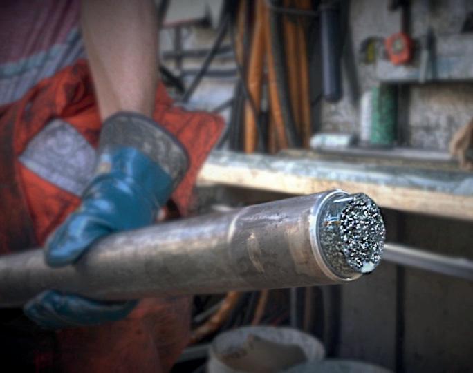

Image courtesy of UNSW and VanadiumCorp 8 A vanadium
drill core from Quebec, Canada
8 Vanadium fl ow
redox battery research
of thermal runaway or fire, can be realised in marine propulsion systems, says Bakker.
Phase I of his plan will see the formalisation of a trilateral partnership with Conoship International Projects from the Netherlands and Vega Reederei and Partners from Germany. VanadiumCorp will contribute new flow-battery designs, a high-energy-density electrolyte formulation, manage research and development and provide its network of manufacturing partners. Conoship will contribute marine engineering designs to integrate a compact redox flowbattery into propulsion systems, and Vega will arrange project financing, contribute fleet operations expertise and conduct field testing of the prototype.
TECHNOLOGY ADVANTAGES
In conventional generation 1 vanadium redox flow batteries, two tanks of vanadium, one containing the negative electrolyte (V2+ and V3+ ions) and the other containing the positive electrolyte (V4+ and V5+ ions) are connected to the battery stacks. Pumps are used to circulate the electrolytes through the battery stacks where power conversion takes place. Most batteries use different chemicals in the positive and negative half-cells which can cross-contaminate and therefore degrade over time. This does not occur in conventional vanadium redox flow batteries as the single element, vanadium, is used to store and release charge.
“The electrolyte never actually degrades,” says Associate Professor Chris Menictas, Head of the Energy Storage and Refrigeration Research Group at UNSW. “It doesn’t change physical state or be used up. When you start from a discharge state, you have V3+ on the negative side and V4+ on the positive side. When you charge it up to 100%, V3+ will be converted to V2+ on the negative side, and V4+ will be converted to V5+ on the positive side. Those processes can just keep going, almost indefinitely. You’re only changing the oxidation state in the electrolyte, you aren’t actually degrading it.” In the Generation 2 technology, the electrolyte is composed of vanadium ions in mixed chloride and bromide acidic solutions. This allows for potentially higher energy density due to higher concentrations of vanadium and utilisation of the bromine reaction.
Having a common electrolyte flowing to every cell is advantageous because it allows all cells in the battery system to be at the same condition, Menictas says. “Quite often, when you have other technologies where you’ve got thousands of cells, some cells may be 60%, some may be 100%. This can cause issues such as imbalance and cell reversal in larger battery arrays.
Additionally, power and energy can be scaled independently. “If I had, say, 2,000 lithium-ion batteries, the amount of power and the amount of time that I can use that power for is fixed, and if I want to add more capacity, for example I need a few extra hours, I’ve got to add more batteries,” explains Menictas. “With the vanadium flow battery, because all the energy is stored in liquid form and the battery stacks are only used for power, if I need more energy or I need power to be provided for a longer time, I can just add more electrolytes. Take a 10 megawatt battery and storage for four hours, so 40 megawatt hours, and if I need 60 megawatt hours, I don’t have to change the battery stacks, I just add more volume of electrolytes. No other system can really do that, other than a flow battery.”
ONBOARD MANAGEMENT
Menictas says most batteries need to be recycled after their useful lifetime, generating an end-of-life financial and environmental cost. “However, in flow batteries, your electrolyte could be worth more and be an asset at that time than it was in the beginning, which is a huge benefit.” Bakker and Menictas anticipate that shipping companies could lease electrolyte, bringing the cost of the technology down dramatically.
Another costly issue for other types of batteries is thermal management, Menictas says. The liquid electrolyte going through the stacks of a vanadium redox flow battery can be used to cool the stacks. “It doesn’t have flammability or explosion issues, so it can be used in a contained environment where it would be an issue with other battery technology that has a flammability limitation that you need to be careful of.
“With lithium-ion, lead acid, or other types of sealed systems, you get heat build-up in the different stacks, especially when you’re drawing a lot of current. And the problem is you need ventilation, active cooling and a lot of active management, which becomes very expensive. In a closed environment, such as a ship, the need for this equipment means the battery system can actually take up more space than an equivalent vanadium redox flow battery.”
The vanadium electrolyte can be stored in a different part of a ship to the stack, making for a flexible installation that facilitates change out of the electrolyte, which could be much like any other bunkering operation. The electrolyte could then be charged using renewable energy sources without the need for costly portside infrastructure and without the vessel needing to remain alongside in port while it occurs.
A SUSTAINABLE RESOURCE
Despite its advantages, the use of vanadium in energy storage technology has been held back by a lack of supply of high-purity metal and by a lack of green production technology. Conventional pyrometallurgical processes are capital intensive, have high operating costs and emit significant amounts of greenhouse gases. “You can’t really have renewable energy unless you have a truly renewable and sustainable energy storage technology,” says Bakker.
As well as owning one of the largest and most metallurgically favourable vanadium mineral deposits in the world, located in Quebec, Canada, VanadiumCorp owns a novel chemical process, invented by Dr. Francois Cardarelli, that overcomes production problems by digesting feedstocks into concentrated sulfuric acid. “Vanadium redox flow battery technology is 100% green when the contained vanadium is produced sustainably,” says Bakker.
8 Vanadium
redox fl ow battery research
NEW FUELS, TARGETS DRIVE 2-STROKE TURBO EFFICIENCIES
Dino Imhof, Head of Turbocharging Solutions, ABB Turbocharging sees scope for further advances in the two-stroke turbocharger segment as dual-fuel demand rises
Advances in turbocharging technology and machinery will continue to play an important part in the industry’s eff orts to meet challenging upcoming IMO greenhouse gas emission and carbon intensity targets.
“Everything is about reducing emissions at the moment,” Imhof said as the industry is focusing relentlessly on meeting upcoming IMO greenhouse gas emission and carbon intensity targets. “The [relative reduction of carbon intensity by 40% compared with 2008] 2030 target is just around the corner.”
The impact of energy efficiency design index (EEDI) requirements was also increasing shipowners focus on fuel efficiency.
ADVANCES IN TURBOCHARGER EFFICIENCY
ABB Turbocharging had responded to shipowner requirements by reducing footprint and increased the power density of its products.
Imhof gave the example of the company’s A255-L and A260-L turbochargers to demonstrate how these advances offered a solution for shipowners operating vessels below 40,000 dwt.
The turbochargers offered a 2% improvement in turbocharger efficiency, and a 30% reduction in space requirements and 50% in weight, compared with the preceding generation of turbochargers.
These efficiency savings were significant in themselves. “We estimate that every 1 percentage point increase in turbocharger efficiency is equivalent to a fuel efficiency improvement of 0.35g/kWh.”
DUAL-FUEL ENGINE DEMANDS
The high efficiency of ABB Turbocharging’s A255-L and A260-L solutions also offered combustion optimisation and higher efficiency advantages for engine designers developing solutions for LNG and other new fuels, Imhof said.
Operating Otto Cycle low-pressure dual-fuel engines efficiently at high loads introduces high requirements for efficiency in scavenging air pressure, Imhof noted. The airfuel mix can make it challenging to maintain combustion stability and avoiding knocking or excessively fast combustion. High-efficiency turbochargers help overcome these issues while contributing to higher break mean effective pressure need to achieve efficient high-load operation.
Imhof noted that a key engine designer of 400mm and 500mm bore low-pressure dual-fuel low speed engines specified a minimum turbocharging efficiency of 69% for turbocharging solutions. “With our A255-L and A260-L turbochargers, we could already meet those requirements. In fact, we have proven on an engine that we can fulfil these requirements,” Imhof said.
However, the turbochargers also meet requirements for increased efficiency at low and partial loads. “We have made an improvement to turbocharger efficiency when the vessel is operating in diesel mode, at low to medium loads.”
The applicability to dual-fuel engines is important as LNG remains the most likely alternative fuel to HSFO and IMO 2020 fuels at present. This is particularly the case in the twostroke segment, where LNG is steadily gaining market share.
One potential area of development focus is the further reduction of emissions from low-pressure dual-fuel twostroke engine solutions. On the engine side, improvements such as reduced crevice volumes, have already led to reductions in methane slip. A further reduction through technical improvements will follow in turbocharging as well as in engine design, Imhof noted.
“A high turbocharging efficiency can ensure a high lambda is maintained in high-load operation, under any condition, thus minimizing the potential for fast combustion,” he explained. “As such, turbocharging can facilitate engine efficiency improvements, by supporting higher mean effective pressure. An improved engine efficiency directly reduces total GHG emissions.”
Looking ahead, Imhof stressed that the technological limits of single-stage turbocharging for two-stroke engines had not yet been reached.
“Turbocharger development is far from plateauing. We expect to see major steps in turbocharger technology for two-strokes in the coming years.”
WIDER SOLUTIONS
From a broader perspective, improving the overall efficiency of turbomachinery is just a part of one of three main routes to reducing greenhouse gas emission: power conversion technology improvements, hydrodynamic advances and better fleet utilisation. Across all these routes, digital solutions are likely to play a role. ABB Turbocharging’s engine optimisation platform ABB Ability™ Tekomar XPERT is already well established and recent digital advances have focused on turbocharger service.
“These solutions include offering data-led intermediate inspections and introducing a fixed price for customers for complete overhaul at dry dock,” Imhof noted. These offerings represent a major step towards reducing lifecycle costs and enhanced ease of service.

8 Dr Dino
Imhof, Head of Turbocharging Solutions, ABB Turbocharging
THERMAL INSULATION OFFERS TURBO TURBINE BENEFITS
Automotive research has demonstrated that the inner insulation of a turbocharger turbine can passively increase the inlet temperature of aftertreatment systems, reducing the need for other optimising options that increase fuel consumption
The research is focused on hybrid automotive drive trains, but increasingly stringent maritime emissions reduction goals mean the results could provide future research potential for marine engine systems. In both cases, the increasing effi ciency of internal combustion engines could signifi cantly lower exhaust gas temperatures.
“Heat flowing down the exhaust is wasted from an engine perspective,” said Dr Richard Burke, head of the research team at the Institute for Advanced Automotive Propulsion Systems at the University of Bath in the UK. “An insulated turbocharger reduces the heat losses so that the engine can run at a more efficient point whilst maintaining the same aftertreatment temperatures compared to a standard turbocharger.
“In automotive applications, the benefits of the increased inlet temperature are most notable during engine warm-up where the engine will be calibrated to take measures that ensure that the aftertreatment warms up relatively quickly. These measures include throttling the engine, injecting additional fuel or recirculating exhaust gases and all come at a cost of lower efficiency (higher fuel consumption) in order to generate the heat in the exhaust.”

Picture courtesy of BorgWarner
Burke and his research partners conducted an experimental study comparing a standard turbocharger to one with an inner insulated turbine housing. They tested a range of transient conditions applied to a 48V hybrid two-stage boosted diesel engine system on a test rig developed by the Institute for Advanced Automotive Propulsion Systems.
The insulation consisted of an inner and outer metal shell with silicate fibre in between. The addition of the insulation was checked to ensure that it did not affect the aerodynamic performance of the turbine. Using 3-D CFE/FEM simulation, it was predicted that external heat losses between the engine and the aftertreatment would be reduced by 70% compared to a standard, non-insulated turbocharger.
The results of the transient experiments demonstrated a 1-3% reduction in fuel consumption and NOx emissions, and a 2kRPM turbo speed benefit was achieved due to the increased turbine inner gas temperature.
The results were used to parameterise a 1-D, lumped capacitance model that could be used to predict the behaviour achieved in the lab. The model matched well for high temperature and low-frequency transient processes.
8 The insulation


