30 minute read
Methane slip


ME-GA EGR PROMISES ‘30-50%’ METHANE SLIP REDUCTION
MAN Energy Solutions’ unveils a new high-pressure exhaust gas recirculation (EGR) after treatment option for its ME-GA engine platform
While the fi nal headline methane emissions reduction was yet to be confi rmed, it was expected to be “30 to 50 percent”, while EGR version would lower specifi c gas consumption by around 3 percent and lowering the specifi c fuel oil consumption in diesel mode by 5 percent. Importantly, the EGR version would allow the ME-GA to meet Tier III requirements in both fuel oil and gas modes without additional aftertreatment.
MAN ES plans to make the EGR option available from late 2021, to the same schedule as the basic and SCR versions of the ME-GA. The technical details of the new version will be available on MAN ES’s CEAS Data platform in October, Hansen said.
The ability to bring the new solution to market in such a compressed timescale partly reflected the fact that MAN ES has extensive experience with designing and delivering lowpressure and high-pressure EGR versions.
“We have 33 EGR engines in operation and 211 engines on order. Our licensees are familiar with our solutions.”
EGR DESIGN
Unlike other two-stroke manufacturers’ Otto cycle lowspeed engine aftertreatment options, MAN has opted for a high-pressure EGR system. While the HP EGR system introduced requirements for a blower and a small associated parasitic load increase, it meant that the system could be integrated into existing engine room designs.
“We can place the EGR on the engine - with the exception of the water treatment system - and the limited volumes of the solution, compared with LP EGR solutions, means it does not require any modification to existing engine room designs.”
The HP EGR to be used with the ME-GA was very similar to the design of EGR systems used with ME-C engines although the material specifications would be adjusted to reflect the properties of VLSFO and LNG, rather than HSFO. This was likely to lower the price point of the ME-GA EGR version, Hansen noted.
Around 30 to 50 percent of the exhaust gas from the engine is drawn into the EGR receiver, where it passes through a pre spray to lower its temperature, before passing through a cooler spray step.
After passing through the EGR cooler stage, and a subsequent water mist catcher, the gas is passed through a blower to increase pressure back up to scavenging air pressure, before being fed back into the compressor and the engine.
The advantages of employing an HP EGR solution also extended to the volume requirements of the system. The solution required less pipework than LP EGR solutions and had a smaller footprint, while a number of design features minimised space requirements.
One such example was the application of an innovative purging concept from the ME-GI Mark II design. Rather than purging the engine by injecting nitrogen from the GVU, returning the gas via the return pipe to the GVU, we simply apply nitrogen at the engine end.
By reversing the flow, the existing piping can carry the purged volume. This lowers the cost of piping, reduces the required components on the engine, and “ultimately we expect it to lead to higher reliability”, Hansen added.
COMBUSTION
While MAN ES’ engineers were initially conducting research into Otto cycle engines, they focused on maximising the fuel efficiency of the process.
“We knew that the engine would require Tier III abatement systems for fuel oil mode, and our abatement experts told us that this technology held out the potential for improvements while they were looking into different solutions.”
However, we found that introducing an EGR solution improved the stability of the combustion process, Hansen added.
A second phase of research into the potential of the technology was underway, examining how the circulation of larger percentages of scavenged air than typically used in
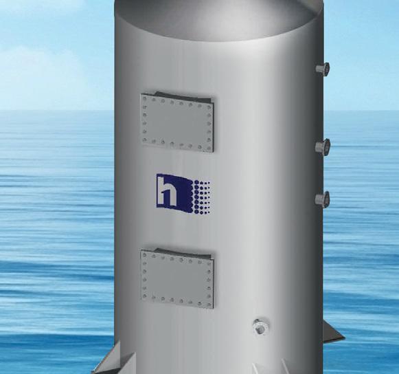
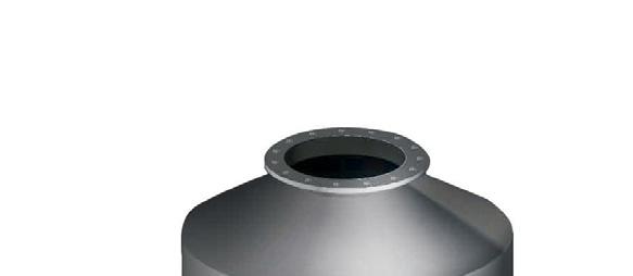
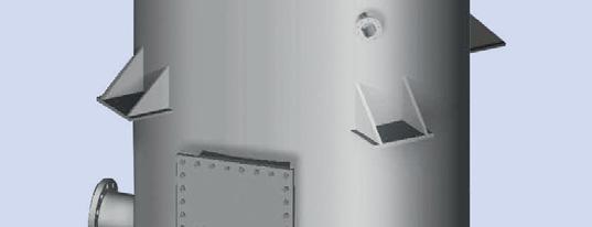
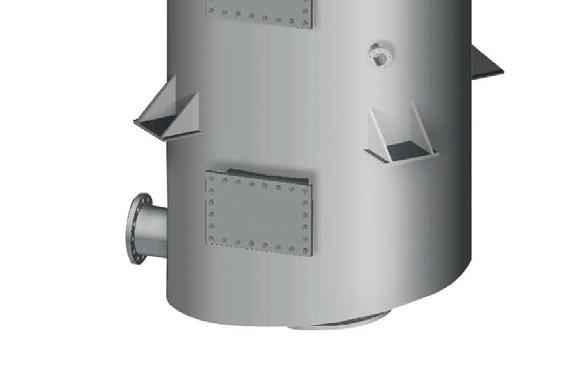
8 A rendering of MAN ES’ new 5G70ME-GA lowpressure engine
EGR versions for diesel engines affected engine operations. “We are currently exploring how far can we lower methane slip while maintaining a good equilibrium with recirculation,” Hansen said.
What was clear was that introducing “a few percent” of the fuel-air mixture in the combustion chamber with recycled inert gases lowered slowed the rate of combustion, and also slowed the rate of pressure rise.
“Adding the inert gases to the fuel-air mixture, lowers the pressure rise rate (dP/dT) of the combustion process,” Hansen noted. “Lowering the maximum pressure, while maintaining the same mean efficient pressure, allows us to ignite the fuelair mixture a little sooner after Top Dead Centre (TDC) with a pilot flame,” Hansen said, “without exceeding the maximum permissible pressure within the cylinder”.
The earlier ignition leads to the significant improvement in fuel economy, as the efficiency of the combustion process is improved.
Hansen noted that the injection also led to more uniform combustion within the combustion chamber. It also reduced mechanical stresses on components within the combustion chamber, as combustion temperatures were lowered and the combustion process became more homogenous.
OPERATING WINDOW
The solution also offers additional benefits for ship owners and operators, Hansen noted. In common with other Otto cycle engines, the ME-GA needs to maintain a lean air-fuel mix to ensure it remains within an ‘operational window’, as too rich a mix can cause it to self-ignite before pilot fuel injection, (‘knocking’) while too lean a mix can cause combustion instability (‘misfiring’).
“We are looking for the sweet spot between knocking and misfiring,” Hansen explained.
The ability to adjust the gas pressure at the engine inlet offered another means of controlling the combustion process in addition to injection timing. In practical terms, this means that the operating window for ME-GA engines will be widened.
This offered significant advantages in terms of managing engines with SMCR above 15 bar mean effective pressure, particularly when the engines are running at high engine load.
The solution will also increase the engines’ tolerance for nitrogen content in LNG, as well as improving their ability to operate in hot ambient conditions without additional equipment, Hansen noted.
METHANE SLIP
In common with other Otto cycle engines, the new ME-GA engine releases a limited amount of unburnt fuel. While MAN ES’s engineers originally focused on maximising the fuel efficiency of the engine, the engineers are currently focused
The proportion of scavenged air being recirculated via the EGR system was currently being finalised. “We are looking at circulating higher percentages than our current HP EGR systems for two-stroke engines,” Hansen added. The question was discovering how far methane slip can be lowered while maintaining a good equilibrium with fuel efficiency.
Although the exact methane slip reduction has not been published, Hansen noted that it would be “extremely substantial”, and MAN ES engineers were looking at achieving savings of 30 to 50 percent.
The EGR solution would help to lower methane slip via improvements in combustion efficiency. The earlier ignition is also likely to lead to a reduction in unburnt gas within crevices and other volumes within the combustion chamber, The Motorship notes.
The recirculation of unburnt methane back through the combustion process would also lead to a reduction of methane emissions, Hansen noted.

ME-GA COMPONENTS
Apart from the EGR, the ME-GA also employed a number of solutions. The ME-GA design features a location of the gas regulating unit on the engine. This offers the use of gas pressure to improve the engine’s dynamic response, in addition to admittance timing.
By designing the gas regulating unit for installation on the engine from the outset, it allows the GVU to be located outside the gas safe area, eliminating the need to install a cofferdam box in the engine room.
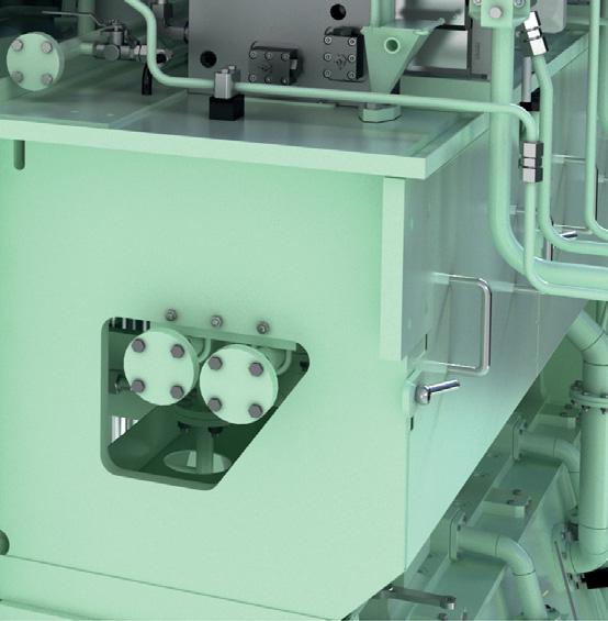
Meanwhile, the engine also employed a safe gas admission valve, placed on the manifold and exhaust side of the cylinder. on a second round of tests to reduce methane slip.
By being located close to the cylinder, it minimises the potential volume that could enter under the piston case in case of a release. “As each valve has a window valve function, you have double safety,” Hansen noted, “all but eliminating the risk of burst discs in the scavenging air receiver.”
ADAPTIVE CYLINDER CONTROL AND TRITON
The ME-GA engine platform is also being launched with MAN ES’s new Triton engine management system. This system is being integrated with all new ME-GA engines, along with MEGI engines. “Triton is being integrated with all new engine types being developed from now on,” Hansen said.
The solution includes an Adaptive Cylinder control function, which is an integral part of the Triton system. The adaptive cylinder control function allows the system to automatically manage the combustion process on each individual cylinder, without any user interaction at all times.
The system constantly monitors the maximum pressure, the compression pressure and the mean efficient pressure on each cylinder, and automatically adjusts them if they deviate from shop test results.
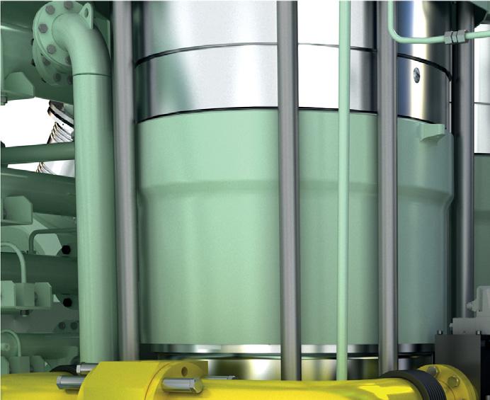
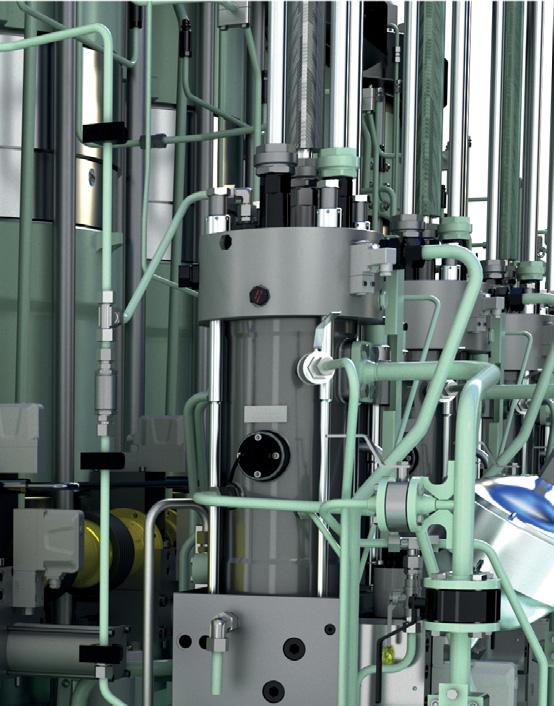
8 The safe gas
admission valve is placed on the manifold and exhaust side of the cylinder
CREATING A FUTURE-PROOF FUEL PATHWAY - NOW
Of all the fuels vying for attention, at the moment LNG alternatives might be best placed to deliver change, hears Stevie Knight
“Realistically, there are three compliant choices right now, scrubbing HFO, using low sulphur heavy fuel oil, or running on LNG” says Mark Bell of SGMF. “Currently, we really only have these three choices on the table, not a lot else, and the clock is ticking.”
It’s a point picked up by Peter Keller from SEA-LNG: “We need to be doing something right now, not waiting two or three decades for a utopian solution.” What the industry needs “is a forward pathway”, comments Jacob Granqvist from Gasum: “If you invest in LNG you are future proofing your ships: biogas becomes a stepping stone on to synthetic, power-to-x solutions”.
Natural gas is primarily composed of methane (CH4), which has four hydrogen atoms to one carbon - though it has less impact than, for example, propane which releases three carbon atoms on burning. However, since liquefied biogas (LBG) is produced from biodegradable sources that would release CO2 anyway, many people argue that it doesn’t, in fact, add to the world’s GHG burden.
But the real beauty of it is that it’s a ready-to-go “drop-in” fuel for LNG engines, says Adrian Tolson of Blue Insight, with an existing physical and regulatory infrastructure. It’s also a case of “future proofing” the supporting ecosystem, adds Keller.
ONBOARD
Certainly, bio-LNG is already being supplied by companies like Gasum, either in blends or as pure methane “with no issues in the engine room”, says Granqvist.
Interestingly, engine manufacturers are right behind the change. Reetta Kaila of Wärtsilä’s Gas Solutions arm explains that “yes, there is a chemical difference in the composition... fossil derived LNG methane numbers [a measure of detonation resistance] can be as low as 65, but bio-methane is close to pure, at 100MN. There are none of the longer, heavier hydrocarbons such as ethane or propane that can reduce the methane number and cause knocking.” Her colleague, Kaj Portin adds that as a result “both bio and synthetic LNG are much cleaner and far more stable in quality”.
There are a few considerations: biogas needs upgrading and drying to achieve the required calorific value. There are a handful of different methods - used both separately and together - to separate it from water and CO2 (the greater part of the mix), and treat the smaller amounts of hydrogen sulphides (H2S), siloxanes and VOCs. Mostly these come down to solvents (amine or pressurised water) and filtration (activated charcoal and membranes).
But there’s no chance “of harmful components sneaking through the system”, says Kaila. The biomethane liquefaction has requirements for extremely low levels of moisture (H2O < 1 ppm) and CO2 (< 50 ppm) to prevent ice or dry ice formation during the chilling process; trace siloxanes and H2S are removed during preparation. “In other words, the liquefaction process itself ensures high quality composition,” she explains.
Widespread take-up could potentially shift engine design. “The fewer changing parameters in the system, the more
paper mill waste
accurate you can be in achieving the lowest emission output. In fact, if a ship can operate completely on pure bio or synthetic LNG, I believe that we might even be able to simplify the engine,” says Portin.
AGEING
Portin explains that fossil LNG ages partly because as it warms, the more volatile methane boils off first leaving a mix that doesn’t have the composition stated on the bunker ticket.
It’s been a nubby issue for the development of an embracing ISO standard. “The problem is that ageing is affected by how the LNG is handled, how it splashes around in the tank, the onboard temperature, so it has been really tricky,” he says.
Alongside this, there have been issues with sudden spikes in the boil-off rate. It can happen when LNG of different compositions stratify into layers which (given heat ingress or sloshing) then collapse suddenly: according to research, rapid mixing and ‘rollover’ leads to vaporisation rates that can be 30 times higher than normal.
There is another concern apart from efficient combustion characteristics: “How do I know I’m getting the calorific quantity that I ordered?” asks Bell: “Am I getting what I paid for?”
All that will be left behind if there’s only bio or synthetic LNG in the tank says Portin, it won’t stratify, and “while the fuel will still boil off, it’s only leaving [identical] methane behind” he explains. No changes in quality means ageing will simply cease to be an issue. Of course, until these purer fuels are widely available, these challenges will still need addressing - although Bell points out gas “has far fewer
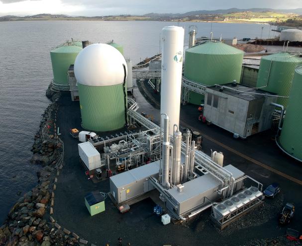
8 The Biokraft
plant inTrondheim/ Norway, produces biogas from fi sh industry and
quality issues than heavy fuel oils”.
recovering 99% of the methane
BIO FEEDSTOCK
However, to gain certification, Bell points out that the feedstock “has to come from a sustainable resource”, at present these are renewable crops, aquatic biomass, forestry waste and agricultural residue, although Adrian Tolson of Blue Insight adds that “theoretically, any organic material can be the feedstock for anaerobic digestion”. “We just have to be broader in our thinking,” adds Keller. In fact, municipal waste and manure are currently utilised, both having more potential for the future: “If you use manure, it’s possible to move to negative CO2 emissions,” adds Granqvist: very attractive given the likelihood of an emission trading scheme for shipping.
There’s already 40m tonnes of biogas manufactured annually. While that current figure still falls short of shipping’s global power requirement, fuel processing plants certainly have enough for the foreseeable future.
Moreover, there’s room to scale up. According to this year’s SEA-LNG-commissioned CE Delft study, there is enough biomass available to feed the whole marine industry. Having said that, ramping up will precipitate sector competition for the resource, admits Kaila “from heat and power plants and biodiesel production, even before it gets to being taken off for bio-LNG”.
TWIST
Of course, there is an interesting point here. Supply chain development is central to raising production capacities, so while biomass can be harvested by truck, after first stage processing, most manufacturers will likely feed it into an existing grid, gas collection taking place at liquefaction hubs close to the ports. That gets around the rather expensive long distance transport.
Why will this matter to ships and engine designers? While there will be an environmental certificate from the producer.... there’s now intense focus on mitigating onboard methane slip.
it won’t, actually, be the same gas as put in at the other end of the pipe. So, the terminology has yet to sort itself out says Kaila, along with the supply chain: “Bio-LNG will have its total environmental impact certified... but the physical tank will hold a proportion of hydrocarbons.” Pure LBM, liquefied biomethane, will only be available where there’s a dedicated supply from the plant.
FOOTPRINT
All this effort could come to nothing, unless detailed well-towake analyses are made for proposed fuels, underlines Keller.
It’s not straightforward. As Bell points out: “To produce synthetic fuels you need hydrogen and production of that, in turn, needs a significant amount power,” further, creating
Photo: SEA-LNG
of retained or captured CO2. If the power for all this isn’t from a renewable source “the carbon footprint does not stack up”, he explains.
“It’s been acknowledged that creating ammonia takes as much energy as synthetic methane,” says Granqvist, and that’s before constructing the infrastructure. Further, running just 3% of the global fleet on a hydrogen-based synthetic “would take all the energy that the Nordic countries produce in a year”, he says. “It’s just not doable.”
Moreover, competition for renewable hydrogen stands to heat up: “Certain players in the steel industry have already announced it will go for green H2... which might affect price,” adds Kaila.
Given all this, bio-LNG comes out ahead. According to that CE Delft study, even traditional LNG’s well-to-wake carbon footprint is 21% lower than current oil-based marine fuels: apply Norway’s cheap hydropower to processing, and it drops even further. Further, bio-LNG can reduce CO2 emissions by up to 90% compared to conventional liquid fuels, says Gasum.
However, “methane is still an issue .... especially in biogas production”, says Tolson. Despite this, SEA-LNG’s lifecycle analysis shows “we are already getting over 20% savings in total upstream GHG emissions”, says Keller, added to which, methane and other hydrocarbons also requires the addition
Costs, too, should come down. While running on an 80:20 LNG/LBG mix “is currently on a par with MGO” says Granqvist; he sees the demand for blends rising with the balance gently tipping toward 100% bio-LNG, “so we are ramping up production and sourcing”, he explains, economies of scale eventually reducing the price.
However, the final take-home message has broad implications: to avoid the clean-up proving counterproductive, “a strict lifecycle assessment is needed for shipping’s fuel alternatives”, concludes Keller.
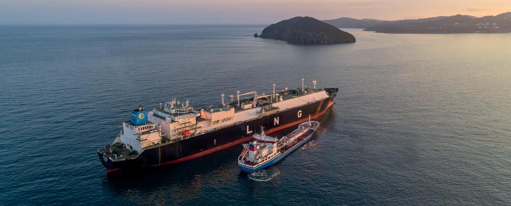
8 The existing
LNG supply infrastructure could put liquefi ed bio-methane ahead
8 Gasum’s LNG
plant in Risavika, Sola municipality, has a production capacity of 300,000t p/a. There is also a LNG bunkering facility for marine customers
Photo: Gasum
ROLLS-ROYCE SEES BENEFITS OF PARALLEL APPROACH
Rolls-Royce Power Systems, the designer of MTU engines and systems, plans to begin full-scale multi-cylinder tests on a spark-ignited low-pressure hydrogen engine design in 2021
The tests had originally been scheduled to begin in 2020 but had been impacted by the coronavirus pandemic, Dr. Peter Riegger, Rolls-Royce Power Systems Vice President Power Lab told The Motorship in an exclusive interview in September.
The tests were among a ‘basket’ of solutions that the company was developing within a new dedicated Power Lab unit, which has been set up to develop innovative and net zero carbon drive and energy solutions.
Alongside a focus on synthetic Power-to-X fuels, such as hydrogen, methanol or synthetic LNG, the engine designer was also ramping up research into fuel cell solutions for both the stationary and marine markets.
HYDROGEN ENGINE RESEARCH
Turning to the initial focus of the Power Lab, Riegger noted that alternative fuels was “the biggest topic”, along with the addition of PEM fuel cell technology to the portfolio.
Riegger previously revealed that Rolls-Royce Power Systems had successfully concluded endurance and component tests alongside single-cylinder tests at its R&D site in Magdeburg and in collaboration with Technische Universität München.
The current engine tests represented a lower power density than gas powered versions show. However, the company had continued to make progress with the impact of ageing on the behaviour of hydrogen, as well as emissions reduction.
By undertaking research into the two main technological branches of hydrogen-fuelled propulsion in parallel, RollsRoyce Power Systems would be well positioned to offer solutions to meet market demand.
It was unclear whether the market would adopt (hydrogenfuelled) fuel cell technologies or whether hydrogen-fuelled reciprocating engines would gain a market share.
A reformation process converting methanol into hydrogen fuel aboard a vessel offered a potential solution to containment issues, for example.
The research that the engine designer was undertaking into hydrogen safety, handling and containment was applicable to both technologies, Riegger noted.
A RENEWED FOCUS ON FUEL CELLS
Fuel cell technology is not a new area of research for RollsRoyce Power Systems. Rolls-Royce developed significant experience working with fuel cells during the ultimately unsuccessful attempts to commercialise molten carbonate fuel cell (MCFC) technology. Between 1999 and 2011 RollsRoyce installed 26 high-temperature MCFC fuel cells systems for power generation in various industrial companies and health institutions with an average of 22,000 operating hours each.
“We invested a lot of time and effort carrying out trials of MCFC also aboard the Viking Lady a decade ago. But the difference is that we can now leverage the multi-billion dollar investments by automotive manufacturers in (PEM) fuel cell technology.”
Rolls-Royce Power Systems plans to start up a PEM fuel cell-based demonstrator unit at its Friedrichshafen research centre at the beginning of next year.
“We have operated a vessel with a PEM fuel cell installation on Lake Constance, and have gained some operational experience,” Riegger noted, adding that a number of technical obstacles needed to be addressed, including designing fuel cells with greater durability to meet the different power demand profile of marine vessels compared with automobiles. The efficiency of the fuel cells was a separate issue.
“It’s not a case of simply sticking a few automotive fuel cells into a vessel,” Riegger noted drily.
Technical challenges for marinizing fuel cells included preventing salt water from entering the fuel cell, owing to the effect of the sodium on electrical conductivity, along with ensuring the hydrogen fuel supply meets the purity thresholds of PEM membranes.
Looking further ahead, Riegger noted that several PEM fuel cell installations aboard vessels were underway but the technology was some way from being a commercial solution.
Cost considerations were currently a barrier but economies of scale were likely to lead to a fall in unit costs as production ramps up.
“I’m completely convinced we’ll see the same decline in unit costs for fuel cells that we saw ten years ago with PV units and five years ago with Li-Ion batteries,” Riegger noted.
POWER LAB – MORE THAN AN ACCELERATOR
“Power Lab is about the technologies of the future. As a company, we believe decarbonisation will be a topic for the whole economy, and will drive demand for carbon-neutral technologies, such as Power-to-X or fuel cells.”
However, Dr Riegger was quite clear that the Power Lab was more than a technology incubator. In fact, the development of the technology only formed one strand of the Power Lab concept.
“We are also establishing the “boundary conditions” of the technology and seeking to develop business models (within
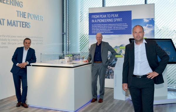
8 The Power Lab
management team: Daniel Chatterjee, Arne Schneemann and Peter Riegger
Rolls-Royce Power Systems’ overall strategy) to ensure that the technology can be commercialised.”
To put it another way, Riegger added, we are taking a broader holistic perspective of the introduction of new technology, rather than narrowly focusing on the development of technical solutions without considering the economic aspects.
The idea is to develop technical solutions, confirm the business case and ultimately introduce the technology as separate units within Rolls-Royce Power System. “This was the approach we followed with the Microgrids technology, which was established as a separate business unit at the beginning of 2020,” Riegger noted.
Riegger added that the company was continuing to develop solutions for its portfolio of reciprocating engines, but that they would be focused on lowering emissions and improving fuel consumption. One such example under consideration was the company’s RCCI research. The company had successfully run multi-cylinder trials on the technology in 2016, and was considering reviving research into the technology.
Rolls-Royce Power Systems was also continuing to participate in research with DVGW (German Technical and Scientific Association for Gas & Water) Research Unit at the Karlsruhe Institute for Technology and other industry partners into the development of a catalytic converter (oxicat) to reduce methane slip from low-pressure gas engines.
COLLABORATIVE APPROACHES
Other areas of focus include the developing of engine control algorithms, along with potential commercial applications of machine learning or AI for Rolls-Royce Power Systems’ markets. [The Motorship notes that RRPS launched an engine condition monitoring solution, EHMS, with ZF in 2019].
Rolls-Royce Power Systems has been active developing digital solutions for its stationary and marine customers, such as the MTU Go! troubleshooting app, specifically created for onsite operators of engines and systems.
Another aspect of the Power Lab concept was to establish collaborations with likeminded companies, Riegger noted.
“It is not possible for any company, even a company like Rolls-Royce Power Systems, to do everything by itself,” Riegger said, concluding “it is about teaming up with others with a similar perspective.”
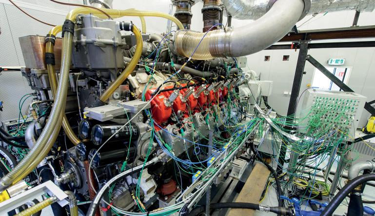
8 Full-scale multicylinder tests on a spark-ignited lowpressure hydrogen engine design are due to begin in 2021
Do ECO with HI AIR SOxScrubber
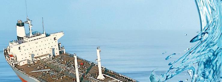


• Easy Installation with Small & Flexible Dimension • Cost Effective with Low Energy Consumption • Operation Friendly with Simple construction


MAN ES UNVEILS 2025 AMMONIA RETROFIT TARGET
MAN Energy Solutions plans to introduce a retrofi t package for its ammonia-fuelled engine by 2025, the company announced in a presentation yesterday
“We are working to have a package ready for retrofi ts by early 2025, approximately one year after the fi rst ammonia engine is delivered to the yard,” Brian Østergaard Sørensen, Vice President, Head of R&D 2-Stroke Business, at MAN Energy Solutions announced.
The retrofit solution is intended to meet demand for lowcarbon solutions to meet the targets set by IMO and some shipowners. Meeting such targets will require solutions to be developed for existing ships, Sørensen noted.
The introduction of a retrofit solution that offers full fuel flexibility would offer shipowners peace of mind, eliminating the risk that assets may become stranded in the future. Similar retrofit packages were already available or under development for MAN ES’ other dual-fuel solutions.
Sørensen acknowledged that regulatory obstacles, ammonia availability (and price) and infrastructure were key constraints to the introduction of ammonia engines.
We are working to have a package ready for retrofits by early 2025, approximately one ‘‘ year after the first ammonia engine is delivered to the yard
“We strongly believe that CO2 pricing will need to be in place to drive the development of the ammonia engine,” Sørensen said.
The existing regulatory regime governing the transportation of toxic products, the IMO International Gas Carrier Code (IGC), and the International Code of Safety for Ship Using Gases or Other Low-flashpoint Fuels (IGF Code) would both need to be developed to permit the use of ammonia, Sørensen noted.
The upgrade package will be aimed at MAN ES’ existing MEC, ME-LGIP and ME-LGI engines, and will draw on MAN ES’ existing modular engine design philosophy. “We want to retain the modules and architecture of existing engine platforms as far as possible, only touching on the components needed.”
The advantages of such a modular approach include improved efficiency and a reduction in cost, Sørensen noted.
UNIQUE FEATURES OF AMMONIA ENGINE
While the engine builds on the existing architecture of the several unique features.
While combustion with pilot fuel injection successfully overcomes the hydrogen carrier’s poor combustion characteristics, MAN is experimenting with other means of reducing the emissions associated with pilot fuel ratios of up to 20%. One of the solutions under consideration was replacing the pilot fuel with a carbon neutral fuel - or by injecting small amounts of hydrogen as an accelerant in the combustion chamber.

As expected, safety issues were among MAN ES’s highest priorities. “Our priority is to ensure that we can purge and vent the engines in a safe manner”. This includes the elimination of ammonia slip when using the nitrogen purging system.
Sørensen added that the engine would require SCR aftertreatment. However, an area of ongoing research was how to prevent NO and NO2 forming of N2O, nitrous oxide. “Processes exist in the chemical industry to eliminate N2O, MAN B&W ME-LGIP engine, the engine design features
but use higher temperatures in the treatment of offgases than exist after our engines.”
8 MAN ES plans
to deliver the fi rst ammonia-fuelled variant of its MELGIP engine by 2024
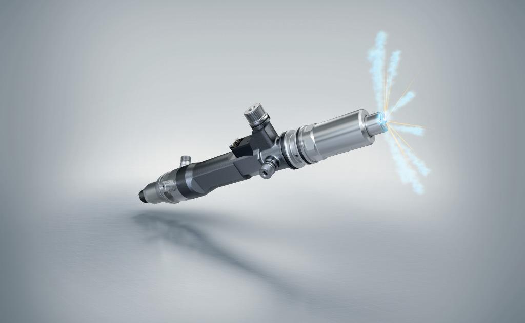
MULTI-FUEL INJECTORS READY FOR FUTURE FUEL FLEXIBILITY
A new family of Woodward L’Orange high-pressure, dual-fuel injectors has been released to deliver future fuel fl exibility
Originally designed for high-speed engines, the new injectors can easily be adapted to medium-speed engines, says Woodward L’Orange, enabling them to run in diesel only or dual-fuel mode with a range of gas or liquid fuels including LNG, LPG, methanol and ammonia. These fuels, when produced from regenerative electrical energy (powerto-X), are expected to help meet IMO’s 2050 greenhouse gas ambitions, but with uncertainty around cost and supply, the new injectors off er the fl exibility to switch fuels during an engine’s lifetime whilst still providing diesel-like power densities and dynamic performance.
Where Woodward L’Orange’s existing GD-series injectors are designed for engine bores of over 320mm, the new injectors are targeted at bores of 170mm. The new injectors have a nozzle tip diameter of 25mm and use diesel as a sealing oil rather than engine oil. They are compact and can be fitted to most engine configurations.

HIGH PRESSURE INJECTION
Today’s emissions limits can be readily achieved by learnburn gas engines with spark ignition or diesel pilot ignition, says Hartmut Schneider, Senior Manager Advanced Development at Woodward L’Orange. However, Woodward L’Orange chose diesel pilot ignition because lean burn
Credit: Woodward L\’Orange
engines cannot use three-way catalysts and therefore produce significant volumes of unburnt methane.
He says the new high pressure gas direct injection and diesel pilot injection technology ensures low methane slip and eliminates knocking. Cylinder outputs typical of diesel engines can be attained without throttling, and diesel-like efficiencies and transient responses are also achievable.
The diesel side of the new injectors is almost the same as a common rail injector and capable of supplying an injection pressure of 2,200 bar to ensure fully optimised combustion. However, the accumulator volume has been reduced to make room for the gas side components.
LOW CALORIC VALUE FUELS
Pilot-ignited, high pressure direct injection also suits combustion of low caloric value fuels even though they require greater injection quantities, and because those quantities are fairly similar, even external components, such as the fuel tank or high pressure pump are similar for some of the fuels.
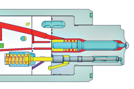
The standard configuration has three gas needles around one single diesel nozzle - a configuration with one diesel and only one gas needle is also possible. For liquid fuels such as methanol, a separate accumulator is integrated into the design.
8 Nozzle with
three concentric gas needles and one central diesel needle
The gas injection jets are positioned concentrically around the diesel pilot and provide gas at injection pressure of 500 bar, up from 350 bar in the GD series. This allows supercritical gas flow with pressure ratios greater than two even at peak cylinder pressures of around 250 bar and ensures mass flow is not sensitive to engine back pressure.
Accumulation volumes in the injector are optimised to provide as much gas as possible close to the needle seats. Pressure losses inside the injector were analysed using CFD simulation and reduced to a minimum. Less than 10 percent of the rail pressure is lost from the injector inlet down to the sachole as a result of large flow cross sections inside the injector.
DIESEL-ONLY MODE PERFORMANCE
For diesel-only mode, the springs connected to the gas needles are forced to seal by tightly guided spring spindles. This ensures the needles seal reliably during peak cylinder pressures in the absence of pressurised gas. The main fuel needles are actuated by an independent hydraulic valve which is placed on top of the injector to save space.
A key feature of the injectors is their installation flexibility, and Woodward L’Orange has already, for example, provided a side-feed and a top-feed version of the injector. “As every cylinder head and air inlet/outlet valve actuation is different on every engine, a different solution is needed for every engine,” says Schneider. “One solution is to use the existing diesel connection of today’s injection valve and either press or screw the quill pipe into the injector housing, but it is still necessary to connect the power-to-X fuel and the sealing oil. This requires additional quill pipes going through the cylinder head either at the same height and a different angle or at the same angle but different heights. If there is not sufficient access or installation space available in the cylinder head itself, the connections can form a ‘crown’ at the top end of the injector. The fluids enter the injector at the top and are guided in internal bores to the nozzle.
“There might also be a combination of all measures with connections in and above the cylinder head, as typically such a project does not start from scratch on a white sheet of paper, but rather as a retrofit to an existing engine.”
Credit: Woodward L\’Orange
The injectors have undergone high pressure methane tests at several German research facilities. Hundreds of hours of engine running time have confirmed that methane slip occurs at negligibly low levels. Selective catalytic reduction exhaust after-treatment is required to meet IMO Tier III standards.
FUTURE FUEL CHOICES
“We see fossil methane as a popular fuel for the next years, but only as a ‘bridge fuel’, as it reduces CO2 emissions by approximately 25 percent only,” says Schneider. “If the IMO goal of CO2 emission reductions of 50 percent by 2050 is to be reached, it has to be a zero-CO2 fuel instead. This might be for example green methane, which is expensive, or ammonia as it does not contain any carbon at all. On the other hand, storing of ammonia is not as convenient as for example methanol, which could also be produced green.” Tests with methanol are currently on-going.
Schneider says that although hydrogen seems very popular at the moment, Woodward L’Orange views it as another bridge fuel, as large fuel cells will likely replace hydrogen combustion engines beyond 2030.
“The race is not decided between the different options,” says Schneider. “It is still not clear which fuel and which engine technology offer the most future-proof investment.” He says the new injectors provide a technology that is ready for most power-to-X future fuel options currently under discussion.
8 The new injectors
are compact and can be fi tted to most engine confi gurations
8 A schematic view

