The Engineer’s guide to new products & design ideas 34: Industry 5.0 Accelerate digital transformation with Industry 5.0 06: efficiencyEnergy ErP directive: Strict energy efficiency classes can also be an opportunity 2021May Additive manufacturing meets Industry 4.0


the results of any actions or omissions taken
Copyright in the contents of Design Products
18:
sponsors of
questions
ErP
E-mail: dpa@imlgroup.co.uk DPA ISSN
journal, published monthly. Completed print or online registration forms will be
Cover Story: 3D-printed wear-resistant parts from igus often offer the same service life as original parts. Now, igus goes one step further and makes the printed components intelligent. p.8 (Cover image: igus) 04: Editor’s comment Paying tribute to Prince Philip and his active interest in engineering Feature: 06: Energy efficiency directive: Strict energy efficiency classes can also be an opportunity
services.
Applications, its websites and newsletters is the
liquid
enclosures DNA
Head Office: IML Group, Blair House, 184/186 High Street, Tonbridge, Kent TN9 1BQ 359990 0965-4747 & property The publisher and the this are responsible for on the basis no liability can accepted result claim based a controlled circulation considered for free supply of printed issues, website access and online Annual subscription for non-qualifying readers is UK £121, EU £215.25, Airmail £315 and single copy price is £18.60Average10,000monthly. net circulation Jan-Dec 2018
Publisher:
springs Safety-critical
Enclosures & Panel Products Special
of any
Excellence
pumps Multi-diaphragm pumps
of the publisher.
automation 34:
ContentsPaige’sPage:
for robust charging enclosures Hydraulics
in
Tel: 01732
optimisation Gold
APEX pumps 24:
Special Report: 20: Butterfly valve seals seals Pump mine to Watson-Marlow Qdos and Bredel Diaphragm &
Accelerate
Design:
Setting
Cover Story: 08: Smart 3D printing manufacturing meets Industry 4.0 Report: 10: Switch bounce How to implement hardware debounce and Cooling Industrial enclosure cooling vs cooling DNA enclosures – transforming the synthetic biology industry E-mobility electric vehicle sales grow, so does the requirement & Pneumatics
for switches
air
06 The Engineer’s guide to new products & design ideas 34: Industry 5.0 Accelerate digital transformation with Industry 5.0 06: efficiencyEnergy ErP directive: Strict energy efficiency classes can also be an opportunity 2021May Additive manufacturing meets Industry 4.0 Tel:Circulation+44(0)1732 359990 Email: subscriptions@imlgroup.co.uk Group Editor: Paige paige.west@imlgroup.co.ukWest
on or in relation to material provided for inclusion. Design Products & Applications is
General
High-performance
of information in this publication. In particular,
pulsation dampers TechnologySprings
36:
relays 14:
Additive
solutions
be
32:
solutions 16:
for butterfly valves 22:
Designing
Production:
magazine
30:
www.grahamrichdesign.co.ukDesign
Assistant Editor: Sophia sophia.bell@imlgroup.co.ukBell Andrew andrew.quenault@imlgroup.co.ukQuenault Holly holly.reed@imlgroup.co.ukReed Graham Rich
As
switchesdpaonthenet.net30203
Focus: 28: Wave springs wave springs: your answered Aerospace spring failure in the Supplement:Manufacturing Robots & jobs the record straight on robotic Industry 5.0 digital transformation with Industry 5.0 Unmanaged switches in network technology: Murrelektronik’s unmanaged
not
switches
aerospace sectors Smart


Prince Philip presented the first Mac Robert Award at Buckingham Palace to recognise the successful development of innovative ideas in UK engineering and its contribution to national prosper ity and international prestige. The 1969 Award was made jointly to Freeman, Fox & Partners for the Severn Bridge and to Rolls-Royce for the Pegasus engine. As early as 1966, CEI members felt that a more prestigious body was needed to provide an effective voice for the profes sion in national affairs, to provide advice to the Government and to recognise eminent engineers and technologists. After discussion with the CEI, His Roy al Highness set down his own vision for a Fellowship of Engineering, includ ing what form and role it should have. Prompted by his strong support, the CEI completed the formation of the Fellow ship in 1976 and the new Fellowship was announced at Guildhall on 9 Feb ruary 1976. His Royal Highness stepped down as President of the CEI and as sumed the title of Senior Fellow of the Fellowship of Engineering. Some 130 engineers, drawn initially from the Royal Society and the professional engineering institutions, were invited to become Founding Fellows. The Fellow ship’s inaugural meeting was held in the Throne Room of Buckingham Palace on 11 June 1976. In 1989, Prince Philip again showed his high regard for the engineering profes sion by agreeing to the commissioning of the Prince Philip Medal, to be “award ed periodically to an engineer of any na tionality who has made an exceptional contribution to engineering as a whole, through practice, management or edu
Thecation”.Fellowship grew increasingly inde pendent of the CEI, both in its vision and activities, until it acquired its own royal title as the Royal Academy of Engineer ing in 1992. Since then, His Royal High ness has given tireless support to the Academy, attending numerous events and adding his voice to its activities, including the Queen Elizabeth Prize for Engineering. In 2012, His Royal Highness graciously agreed for the newly refurbished London home of the Academy, 3 Carlton House Terrace, to be named “Prince Philip House”. Prince Philip and his interest
in engineering and technology Connect with us on LinkedIn. Join us on Twitter Follow us on Instagram.4 dpaonthenet.net
The Duke of Edinburgh portrait (Wikimedia/Author: Donald McKague) Paige West, Group Editor
“We will always be indebted to Prince Philip for his active interest in engi neering and technology. His genuine enjoyment and passion for engineering were evident in his many visits to the Academy and his typically challenging discussions with the engineers he met. He has been a staunch supporter of UK industry and presented the Academy’s highest award for UK engineering, the MacRobert Award, almost every year since it began in 1969.”
Professor Sir Jim McDonald FREng FRSE, President of the Royal Academy of Engineering, says: “As our Senior Fel low, HRH The Duke of Edinburgh has worked tirelessly to support the Acade my, right from its inception in 1976, as the Fellowship of Engineering.
HRH The Duke of Edinburgh was always a keen advocate of the role and impor tance of engineering in society. He was closely connected with engineering in his early career as a naval officer during and after World War II, and it was his vision that led subsequently to the for mation of the Fellowship, later the Royal Academy of Engineering.
W elcome to the May issue of DPA!
Paige’s Page Paying tribute to
active
In 1965, His Royal Highness became President of the Council of Engineer ing Institutions (CEI), which was then formed of 12 professional engineering institutions. The new President was con cerned that the CEI should create a path for engineers, anywhere in the profes sion, to reach professional status. This was achieved in 1971 with the formation of the Engineers’ Registration Board and the creation of different professional lev els, such as Chartered Engineer.


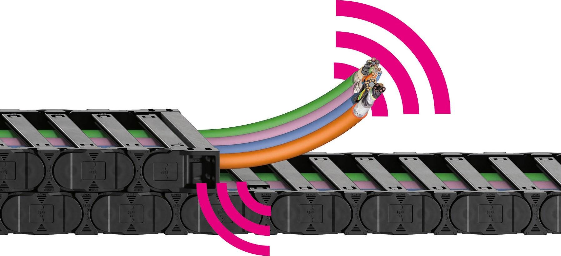
Industr y 4.0: smart plastics eliminate downtime Intelligent products give a maintenance alert ahead of time and can be integrated into standard predictive maintenance; smart plastics allow your equipment to run continuously as well as reducing maintenance costs. igus.co.uk /smar plasticssmarttAvoidunplanneddowntime

Feature:dpaonthenet.net efficiency
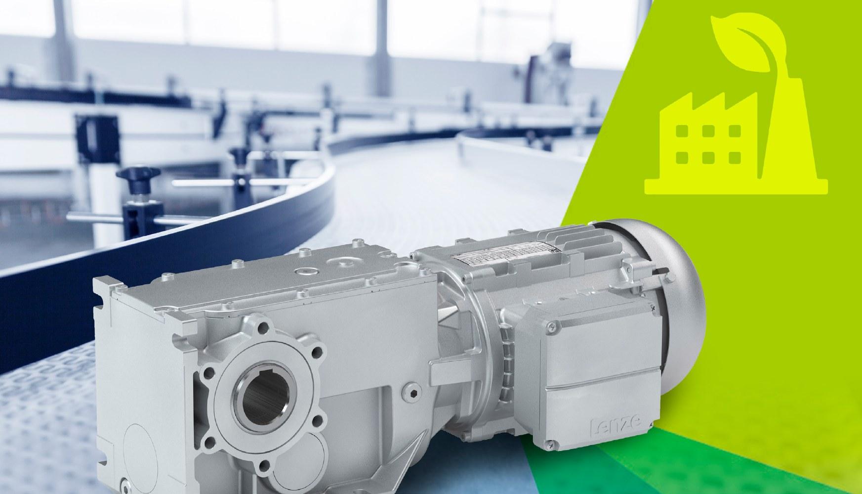
For the first time, motors with a power of 0.12 to 0.55kW will also be subject to energy requirements. Machine builders will, therefore, have to think about how the new motors can fit into their designs – a challenge they will not have to take up alone. Lenze is doing everything to make the changeover as easy as possi ble for the market. Since 2009, Europe has been taking steps to reduce the energy consumption of electric motors because they repre sent an important part of the energy bill of the industry. But what makes the new phase, starting in July, so special is that, for the first time, electric motors with small capacities are also targeted (IE2) – and many exceptions in the already ex isting efficiency class, IE3, will disappear.
ErP directive: Strict energy efficiency classes can also be an opportunity
Lenze’s changeover tool for easily finding the new motor
Lenze Product Manager, Florian Breker, says, “About 70 percent of the energy consumption of industrial drive systems consists of the mechanical and electrical components, such as [the] motor and actuator. They are, therefore, an impor tant lever for improving energy efficiency. Today, only one in ten machine builders uses IE3 motors, due to a multitude of exceptions that are still permitted. Fortu nately, machine builders still have until 1 July to work with Lenze to achieve the new CE approval for their machines.”
The call for more energy efficiency is not a European monopoly, by the way. “Worldwide, there is also a clear trend towards IE2 and IE3,” adds Francis Denayer, Sales Manager in BeLux. “We therefore help machine builders who export, to come up with a single design that complies with the requirements throughout the world. These new regula tions are also the perfect stepping stone to standardise machines more.”
6
Energy
Recognising that this transition requires a serious effort from machine builders, Lenze is doing everything it can to keep the threshold as low as possible. “First of all, in the design of our own compo nents: in order to make integration as smooth as possible, we have designed the motors more efficiently, without F rom 1 July, the new phase of the ErP directive will come into force for electric motors. With this ecodesign directive, Europe wants to encourage manufacturers to bring more energy-efficient products into the market.
MELFA ASSISTA is the new generation of collaborative robot which redefines the perception of what is possible. Combining the best attributes of industrial robots and combining them with the collaborative robot, we have designed a cobot without compromise. Independently tested to meet ISO TS/15066 safety standards, the ASSISTA is proven to be safe working alongside its co-workers, without the need for guards or safety sensors and there is an integrated LED light ring to communicate its status. Integration is made easy with a new intuitive and visually-based programming environment, this interacts with the cobot’s direct teaching and forearm-mounted key pad. To find out more contact us on automation@meuk.mee. com, call 01707 276100 or visit gb3a.mitsubishielectric.com
Close working is no longer a close call.
@meukautomation mitsubishielectric-automationsystemsuk
n Safe collaboration with co-workers n Rapid and easy set up n Simplified application development using intuitive programming n Positioning accuracy of ±0.03mm n Designed to meet the needs of Industry 4.0 Setting the new standard with a truly industrial collaborative robot making big leaps, and we have also tried to optimise the length – for example, with our brand-new integrated encoder system. But we can’t ignore the electri cal differences in the motor to improve that energetic performance,” Breker says. Therefore, Lenze has developed an online changeover tool for its cus tomers that points them in the direction of the best-fitting, more energy-efficient motor, based on the existing parame ters. Denayer explains, “The idea behind it was to help our customers choose ex actly which motor they needed, without having to go through all the catalogues themselves. Now, an alternative is pro posed based on the existing engine, complete with item number, step file and all possible technical documents – a tool that has been used extensively in recent months. And, of course, our experts are always on hand for further technical ad vice.”
View entire driveline A new engine, a machine design that may or may not be adapted...there will be additional costs that machine build ers prefer not to pass on to their cus tomers. Lenze recommends looking beyond just replacing the motor. “To go one efficiency class higher, you have to add about 20 percent of the cost of the motor. Ultimately, the motor only con tributes 10 percent of a machine’s full savings potential. Take this opportunity to take a technological look at your en tire machine,” says Breker. “Technology has not stood still in recent years. Drive sizing is a good example of this. It has often grown historically, but there is a lot of potential for savings, by reviewing the entire drive train. 80-90 percent of the savings potential lies in efficient drive dimensioning, use of fre quency converters, efficient motion con trol, and use of braking energy. “We are happy to make the Drive Solu tion Designer Tool available to our cus tomers, free of charge, for this purpose,” Denayer adds. “If you can reduce the cost of maintenance for end customers or reduce the complexity of operation, they will be more willing to pay the extra cost, especially if you can demonstrate that you can create a lot of added value by adding new features. A system solu tion with Lenze controllers, and the vari ous software applications available, can help to implement this quickly and easily in a “Seemachine.theobligation of ErP directive change as an opportunity to create even more added value to build future-proof machines for the end users,” Denayer concludes. https://www.lenze.com/en-gb/
Feature: Energy efficiency


and makes the printed componentsintelligent.Coverstory:
8 dpaonthenet.net
igus goes
Manufactured using 3D printing, the parts warn of overload and report their maintenance needs. The special feature: the sensors are printed directly into the component. This means that short deliv ery times and low cost are complement ed by Industry 4.0 options. Additive manufacturing and Industry 4.0 – two themes that are changing the industry in a sustainable way. igus engi neers have now succeeded in combin ing the two in a single production step: sensor technology is printed into the tribo component by multi-material printing for the first time.
“With the smart 3D-printed bearing, we have made a real breakthrough,” says Dean Aylott, who is responsible for 3D Now, one step further Smart 3D printing
Additive manufacturing meets igus makes 3D-printed Tribo components 3D-printed wear-resistant parts from igus often offer the same service life as original parts.
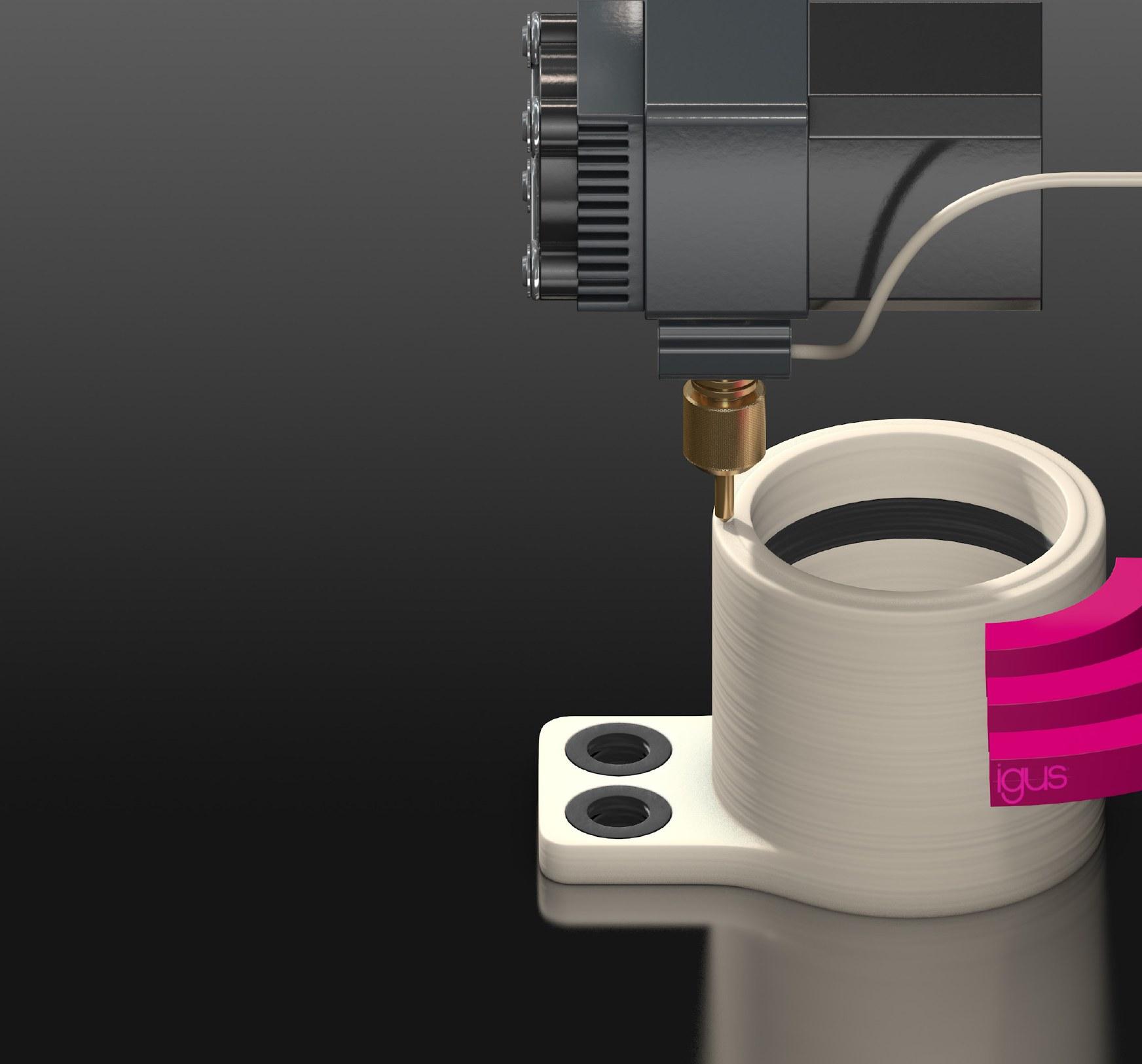
meets Industry 4.0: components smart printing at igus UK. “This allows for pre dictive maintenance to be added to spe cial parts, while keeping costs very low.” Well before the failure, the intelligent 3D-printed part reports that replacement is imminent. In addition, it can detect overload to stop the application immedi ately and, thus, prevent further damage to the machine or the entire plant. Wear or load is monitored Since 2016, igus has been producing intelligent wear parts in energy chains, plain bearings, and linear guides. At first, plain bearings were produced using laser sintering. These were man ufactured from iglidur I3 and the intel ligence was subsequently introduced in a second processing step. Howev er, the production of intelligent special parts with small quantities was expen sive, as the processing steps are very specific to the respective component.
Currently,material. two applications are possible:
• Reaching the wear limit: The con ducting path is located within the slid ing surface, the wear is measured via the change of the resistance. Predictive maintenance is possible with the 3D-printed component. The lubrication and maintenance-free part indicates that it requires replacement, avoiding plant downtimes in advance. This allows the customer to be able to plan scheduled maintenance. If the 3D-printed components are also used in the pre-production phase, the wear or load data collected provide additional information about the service life of the individual component. This makes it easier to adapt and optimise the design Interestedprocess. parties can register for a beta test here: www.igus.co.uk/3d-beta-tester
The engineers at igus are now able to produce these intelligent consumables in just one step, using a new process. No further processing steps are neces sary and intelligent special wear parts can be produced at a low price point in five working days. During printing, the sensor layer is applied to those parts of the component that will be subjected to load. Based on the procedure for mul ti-material printing, wear-resistant parts with integrated sensor layers are devel oped. The components are made from the wear-resistant filaments, iglidur I150 or iglidur I180, and a specifically devel oped electrically conductive 3D printing
This is just one of many new 3D printing technologies that igus is presenting this year. For anyone interested, igus offers individual guided tours at the virtual exhi bition. Further information can be found at https://exhibition.igus.co.uk/
Cover story: Smart 3D printing dpaonthenet.net
• Warning before overload occurs: The electrically conductive material is situated between the wearing layers. If the load changes, the resistance also changes. To determine the load limits, the bearing has to be calibrated.
igus prints intelligence in 3Dmanufactured components and makes predictive maintenance possible for the first time, at a low price point. (Source: igus)
9

Aswitch is a component that can “make” or “break” an electrical circuit, thereby interrupting an electric current or diverting it from one conductor to another. There are many different types of switches, including toggle switches, pushbutton switches, micro and limit switches, and relays. All have one thing in common: they bounce.
Ordinarily, this bounce has little or no effect on the circuit, but if the digital circuit is fast enough to detect and re spond to multiple bounces, there can be serious consequences. An engineer’s task is to avoid or mitigate the effects of this bounce, or “debounce” the switch. While the industry has long practised hardware debounce, it has more recent ly moved to software-based debounce approaches. However, there are situ ations where hardware debounce is a better option. What is switch bounce? When a switch or relay is flipped or tog gled, what a human perceives as being an instantaneous single response may actually involve 100 or more make-orbreak actions. These persist for sever al thousandths of a second before the contact finally settles in place. For example, consider a single pole, single throw (SPST), normally open
Feature: Switch bounce 10 dpaonthenet.net
Figure 1: In the case of an SPST-NO toggle switch, bouncing may occur both when the switch is activated and deactivated. (Image source: Max Maxfield)
How to implement hardware debounce for switches and relays when software debounce isn’t appropriate


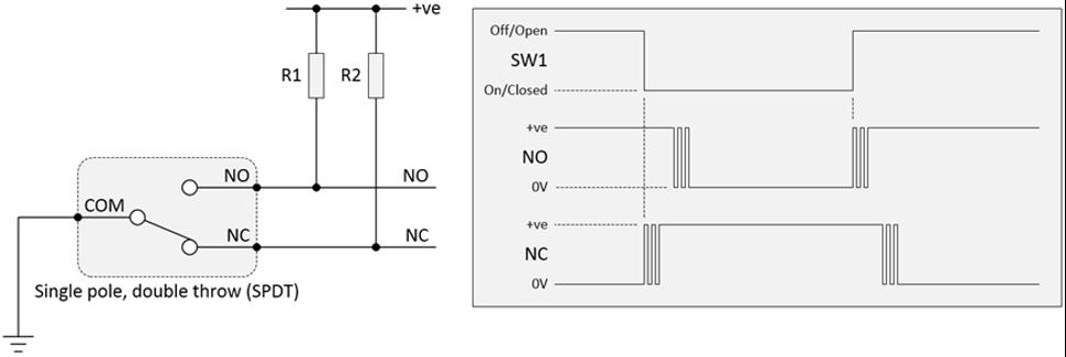
Figure 2: In the case of an SPDT toggle switch, bouncing may occur on both the NO and NC terminals when the switch is activated and deactivated. (Image source: Max Maxfield)
(NO) panel mount toggle switch – like an M2011SS1W01 from NKK. Assume that one side of this switch, which can be considered the input, is connected to ground (0 volts), while the other side – which, in this case, is the output – is connected to a 5-volt power supply (shown as +ve), via a pull-up resistor (R1) (Figure 1). Observe that switch bounce may oc cur both when the switch is activated (closed) and deactivated (opened). Sometimes, the bounces may tran sition all the way between the supply rails, here considered logic 0 and 1 states. In this case, these are “clean” bounces. By comparison, if the signal reaches only an intermediate voltage, these are referred to as “dirty” bounc Ines.the case of a single pole, double throw (SPDT) panel mount toggle switch – like NKK’s M2012SS1W01BC – bouncing may occur on both the normally open (NO) and normally closed (NC) terminals (Figure 2). In this case, only “clean” bounces have been shown for simplicity. In many cases, this signal bounce duration is such that it has no effect. Problems arise when a switch is con nected to a piece of electronic equip ment that is fast enough to respond to multiple bounces. What is required is a way to debounce the signal coming from the switch, before it is acted on by the electronic equipment.
Hardware debouncing an SPST switch with an RC network One of the simplest hardware-based switch debounce solutions employs a resistor-capacitor (RC) network, in con junction with an SPST switch. There are many variations of such a circuit. One of the more versatile implementations involves two resistors and a diode (Fig ure When3). the switch is activated, capacitor C1 is discharged via resistor R2. If diode D1 had been omitted from this circuit, then when the switch was deactivated, C1 would be charged via resistors (R1 + R2). However, the presence of D1 means that C1 will be charged only via InR1.some cases, only the activation of the switch is of interest (i.e., triggering actions to occur) – which means that D1 may be omitted. However, if actions are to be triggered when the switch is
11
Figure 3: When using an RC network to debounce an SPST switch (top), the addition of the diode (D1) forces the capacitor (C1) to charge via resistor R1 and discharge via resistor R2. (Image source: Max Maxfield)
Also, many software developers are unfamiliar with the physical character istics of switches: in addition to vary ing from one activation to another, the bounce characteristics of a switch may be affected by environmental condi tions, like temperature and humidity. The issue of software developers’ lack of switch expertise is exacerbated by the fact that available literature regard ing switch bounce is often confusing and contradictory. For example, it’s common to read that a switch will have stopped bouncing one millisecond (ms) after its activation or deactivation. However, well-known embedded sys tems expert, Jack Ganssle, performed empirical tests on a variety of switch types for both the opening and clos ing of the contacts. Having activated each switch 300 times, he reported an average bounce duration of 1.6ms and a maximum bounce duration of 6.2ms. Some industrial and military “best practices” recommend waiting 20ms after initial activation, before assuming the switch has stopped bouncing; oth ers advocate waiting 20ms following the final detected bounce, before trig gering any Furthermore,actions.many simple non-pro cessor-based systems require switch es to be debounced. A few examples of such systems are seven-segment displays, counting pulses from a relay; the trigger input to a 555 one-shot tim er being used as a motor control for a door or gate; and a register-based fi nite state machine (FSM) that employs keyed inputs. There are also electronic trim potentiometers (pots) with val ues modified using switch inputs (up, down, and sometimes store), where switch bounce would be problematic. All these examples make it clear that some knowledge of how to perform hardware debounce can be useful for any designer or developer.
Software versus hardware debounce In the 1960s and 1970s, switch de bounce was implemented using a variety of hardware techniques, from simple resistor-capacitor (RC) delay circuits, used with SPST switches, to more sophisticated set/reset (SR) latch Morefunctions.recently, and because many sys tems feature a microprocessor unit (MPU) or microcontroller unit (MCU), it has become commonplace to use software debounce. However, this is not always the best approach. In ap plications that involve small, low-per formance, memory-constrained pro cessors (with limited code space and/ or clock cycles available to implement debounce routines), a hardware imple mentation may be a better solution.
Feature: Switch bounce dpaonthenet.net

The bouncing signal from a switch is often debounced using software, run ning in a microcontroller. Although this is a low-cost solution, it may not always be the best option, including systems based on performance and memo ry-limited microcontrollers, software de velopers lacking expertise in switch-re lated issues, or systems implemented without a microcontroller. As an alternative, debouncing may be performed in hardware, using a variety of approaches – ranging from resis tor-capacitor networks to SR latches, to dedicated integrated circuits.
https://www.digikey.co.uk/
Figure 5: Using a dedicated three-channel LS18-S chip to debounce an SPDT switch (six- and nine-channel devices are also available). (Image source: Max Maxfield)
Unlike some of the other dedicated IC solutions, LogiSwitch debounce devic es don’t require any additional compo nents, such as an external clock, an RC timing network, or pull-up resistors on the inputs or outputs. The LS18-S uses LogiSwitch’s propri etary adaptive NoBounce technology, which offers a high level of noise im munity. Noise spikes of less than 20ms duration are prohibited from starting or terminating a cycle, and outputs are de layed for a period of 20ms, following the final switch bounce on both activation and release – regardless of the bounce duration. Conclusion If unmitigated, switch bounce can cause microprocessors and other electronic circuits to see a single switch activation as comprising multiple events.
12 Feature:dpaonthenet.net Switch bounce
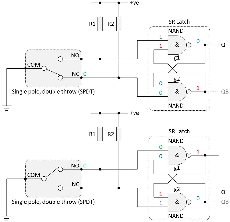
both activated and deactivated – and if minimising delay is a consideration – the addition of D1 is recommended. Observe the exponential charging and discharging curves exhibited by the capacitor voltage VC. It would not be a good idea to feed this signal direct ly to the input of a downstream digital logic function, which wouldn’t appreci ate seeing a signal that dawdles in the undefined region between “good” logic 0 and logic 1 values. Instead, this sig nal is fed to the input of a buffer with a Schmitt trigger input. Furthermore, an inverting buffer is typically used, such as one channel of a CD74HC14M96 from Texas Instruments, because inverting functions switch faster than their non-in verting counterparts. Debouncing an SPDT switch with an SR latch In the case of an SPDT switch, a com mon hardware debounce solution is to employ an SR latch. Ever since compa nies like IBM used this technique for the switch panels on their mainframe com puters circa the 1960s, this approach has been regarded as the crème de la crème of simple hardware debounce solutions. Such a latch can be formed using two back-to-back two-input NAND gates; for example, by employing two channels of an SN74HC00DR quad two-input NAND IC from Texas Instru ments (Figure 4). When the switch’s NC terminal is con nected to ground, as shown in the upper half of Figure 4, this forces the output of gate g2 to logic 1. In turn, the two log ic 1s on the inputs to gate g1 force its output to logic 0. By comparison, when the switch’s NO terminal is connected to ground, as shown in the lower half of Figure 4, this forces the output of gate g1 to logic 1. In turn, the two logic 1s on the inputs to gate g2 force its output to logic 0. This circuit works so well because when both of its inputs are in their inactive logic 1 states, the SR latch remembers its previous value. As illustrated in Fig ure 2, when an SPDT switch is toggled, whichever of its terminals is connect ed to ground, at that moment in time, bounces first. Since these bounces are between its original value (logic 0) and its new value (logic 1), they have no effect on the current state of the SR latch. It’s only after this terminal ceases to bounce that its counterpart starts to bounce, at which time the SR latch changes its state. Debouncing an SPST switch with a dedicated device One problem with the previous solution is that many designers prefer to use SPST switches because they generally cost less than SPDTs. There are several well-known dedicated SPST debounce devices on the market, such as the MC14490DWG from ON Semiconduc tor and the MAX6818EAP+T from Max im AnotherIntegrated.manufacturer, LogiSwitch, of fers a suite of three-channel, six-channel and nine-channel debounce solutions in both through-hole and surface mount device (SMD) packages. For example, consider a circuit using a LogiSwitch LS18-S device (Figure 5). Like all members of the LogiSwitch family, the LS18-S supports an oper ating voltage range of 2.5 to 5.5 volts (the value of the supply voltage does not affect the device’s response time).
Figure 4: Using a NAND-based SR latch to debounce an SPDT switch is a very effective hardware debounce solution. (Image source: Max Maxfield)

Part of the 4most Electronics Technology Group: evconnectors.com | enclosures4u.com | ipjoysticks.com | rotaryswitchesonline.com For further details of our extensive product range please call or email us on: T +44 (0) 1371 811171 E info@4most.co.uk www.4most.co.uk Systems ConfiguratorOnlineBackplanes& CABINETS & ENCLOSURES 4Most Electronics: Importer and specialist distributor of E-MECH products UK Primary source and Channel partner for nVent SCHROFF nVent SCHROFF electronic cabinets are designed to help you keep your systems running smoothly for the long term. Including industrial controls, electrical components, data communications and electronics in virtually any environment. Thousands of standard products as well as tailored solutions with the lead times you need to keep your project on schedule. 19EnclosuresMetalInchCabinets Power Supplies & Accessories PCB Accessories & Retainers Cases & Front Panels Subracks Industrial & Commercial Cooling/Heating Protection from the elements


Industrial enclosure air cooling solutions vs liquid cooling solutions
The first step is to consider what constitutes suitable cooling to meet your needs, bearing in mind that your cooling needs may alter with any future changes to applications within your facility. It’s common for managers, when choosing a cooling solution, to default to air cooling using fans and filters, because it’s familiar. While air cooling can be a viable solution, it also has its limitations, which must be understood before it’s installed. Otherwise, you risk creating problems further down the line. Air cooling Air cooling is relatively self-explanatory. The cooling is achieved by passing cooler, outside air across the enclosure’s warmer internal components. However, it should be kept in mind that this simplicity has its shortcomings. If, at any point, the temperature within the facility exceeds the maximum allow able temperature (setpoint) inside of the enclosure, then no cooling will be pos sible. A good example of this is during the height of summer, when the com bination of lots of machinery and high ambient temperatures can cause severe temperature spikes within the factory. These will quickly lead to overheating componentry and unexpected tripping of critical equipment. But this is only an issue if your factory is prone to surges in temperature. For many organisations, there is an acceptable level of general HVAC installed to ‘take the edge off’ the temperature, allowing air cooling to create a protective environment for the equipment within the enclosures. Dust is a constant irritant within a factory
Feature:
Almost without exception, industrial environments are hostile spaces for electrical equipment: their components don’t react well to high levels of moisture, dust, and heat in the atmosphere. This sensitivity, in turn, affects plant efficiency and will ultimately lower output and profitability. However, moisture, dust and heat don’t need to be a concern, provided you implement an effective climate control solution for your equipment. Cooling 14 dpaonthenet.net

Much like air cooling, regular mainte nance of the system is strongly recom mended to ensure the cooling equip ment can provide years of uninterrupted Inservice.summary, both solutions are valid in the right scenario. However, choosing a cooling solution without first considering its operating environment is setting yourself up for a less than perfect result. This, in turn, will have an impact on the overall effectiveness of your chosen cooling solution and the ongoing protection of your critical electrical Furtherequipment.information at www.rittal.co.uk and www.friedhelm-loh-group.com or on Twitter @rittal_ltd. Cooling About the author: Karl Lycett, Rittal UK’s Product Manager for Industrial and IT Climate KarlControlLycett began his career as a mechanical design engineer, before moving into ofonadvicebasesupportHisIndustrialfocusesManagerClimateHeworkingmanagementproductwhileforEaton.joinedRittalasControlProductin2017andonboththe&ITmarkets.mainfocusistotheUKcustomerbyprovidingexpertandsalessupportthecompany’srangeinnovativesolutions.
Liquid cooling As mentioned previously, it’s common to find traditional air-cooling methods are unviable or simply not especially effective in industrial spaces. This can be due to factors such as the location or amount of the equipment involved, or it can be down to physical space Liquidrestrictions.cooling, however, is an option open to all, and one that is much more effective than air at removing waste heat and reducing the temperature within the Liquidenclosure.cooling, as the name suggests, uses chilled water to perform the cooling of the enclosure. An ‘air-to-air heat exchanger’ is mounted on the enclosure and connected to an industrial chiller. The chiller cools down heated water from the enclosure to a reasonable temperature, before delivering it back to the heat exchanger. The beauty of liquid cooling is that it is ‘active’, which means that you can make the internal temperature lower than that of the local environment. So, even in the height of summer, with the factory in full swing, your electrical equipment will be protected. Many industrial sites already have an operational chilled water supply to service other procedures and equipment. Where this is the case, it can be tapped off and used for enclosure Liquidcooling.cooling requires hydraulic hoses (cold water in, hot water out) to be connected between the heat exchanger and the chiller. It’s therefore worth giving prior thought to both the enclosure placement and where to run the hoses, to ensure the smooth commissioning and operation of the whole system.
and, realistically, it can never be fully removed. Even the ‘cleanest’ industrial space will have a base level of detritus within the air, which will then be drawn into enclosures if fans are employed. Unfortunately, this dust can get into wire connections or internal component fans and cause havoc over time, either preventing thermal exchange or blocking up and shorting wiring connections. The best way to prevent dust issues from arising is to add a suitable filter medium to your air cooling. Filter mediums (or mats) ‘catch’ particulates before they enter the enclosure. The mats should be replaced on a regular basis to prevent a build-up of dirt which can then ‘choke’ the fan, preventing it from pulling sufficient cooling air into the enclosure.
Feature:
1455, 1457 IP65 and 1457-EMI extruded enclosures Learn hammfg.com/1455,more: /1457, /1457-emi Contact us to request a free evaluation sample. uksales@hammfg.com • 01256 812812 new sizes!


The enclosures will allow Evonetix to increase its testing capacity and DNA synthesis, following on from significant growth in 2020. Evonetix now has six prototype instru ments on site using Round Peg Cam bridge’s modular enclosure design. Round Peg Cambridge is extremely proud to play its part in supporting the synthetic biology industry by providing expertise across multiple engineering emailForsolutions.moreinformation,contact.us@round-peg.com, or visit www.round-peg.com
Evonetix’s technology enables the par allel synthesis of DNA on silicon arrays, to facilitate the fast-emerging field of synthetic biology, where there is in creasing demand for high-throughput and highly accurate DNA synthesis.
In 2015, a breakthrough in DNA synthesis led to the creation of Evonetix, a Cambridge-based company that opens the door to numerous opportunities in synthetic biology, from healthcare and pharmaceuticals to food and agriculture, materials, and industrial technologies. Round Peg Cambridge is currently designing a new versatile modular range of enclosures aimed at the life science, biotechnology and ink-jet industries. – transforming the synthetic biology industry
16 Feature:dpaonthenet.net DNA enclosures Round Peg Cambridge & Evonetix DNA enclosures
Round Peg Cambridge has been closely involved with Evonetix since the company was founded. Working in partnership with the company’s engi neering teams, Round Peg Cambridge has been designing and developing solutions for their DNA synthesis pro Astotypes.Evonetix has expanded, its suite of prototype instruments, and their size and complexity, has grown. The suc cess of the company’s initial bread board prototype and its enclosure spawned a new project with Round Peg Cambridge to upgrade the enclo sure design. The brief Evonetix required a flexible solution to allow it to accommodate its early-stage instrument prototypes in-house. Previ ously, it had an early prototype housed in a fume hood in its laboratories. The existing platform that the company was using became unfit for purpose over time: it was difficult to move and awk ward to use. Round Peg Cambridge worked with the client to develop a platform that allowed a broad range of Asexperimentation.researchand development pro gressed, Evonetix needed the flexibil ity to be able to move this instrument easily and safely to different locations on its site, and to maintain and upgrade the system constantly, as technology developed. A major benefit was the improved useability of the instruments in the enclosures, compared to them being housed in a fume hood – being able to move 360 degrees around the instrument allowed easy access for sci entists and engineers. After the design phase, Round Peg Cambridge managed the supply chain and built the platform on site at Evonetix’s lab – a key turning point of the project which simplified the process for the client. This was the first custom enclosure that was built for Evonetix, so it needed to be a functional workhorse, with the ability to adapt to different sit uations. As the client’s requirements were refined, and it gave feedback on the use of the platform, Round Peg Cambridge was then able to move to the next build phase and develop more specific-use cases.


FAST - RELIABLE - SERVICE Flame Hardeners’ customers can rely on a level of service that is among the best in our industry tel: 0114 276 8167 fax: 0114 273 8657 FLAME LIMITEDHARDENERS Incorporating Induction Hardeners Limited Shorter Works, Bailey SheffieldLane,S13BL WWW.FLAMEHARDENERS.CO.UK Find out more at mail@flamehardeners.co.uk As standard we provide* –• 3 day turnround on 80% of all jobs • Less than 2 days average time for bespoke tooling development • 4hrs maximum for written quotations on 80% of enquiries • Personal service – no automated call systems *Non-standard enquiries, large components or specialist requirements may take a little longer www.kemtron.co.uk +44 (0) 1376 348115 · info@kemtron co uk RFI / EMI shielding gaskets & components Kemtron GENERIC.qxd:Layout 1 12/10/2017 13:36 Page 1


Chris Lloyd, Managing Director at Spels berg, explains the key drivers behind e-mobility enclosure design. In 2020, more than 10 percent of all UK car registrations were for electric vehicles (EVs). The gathering pace of EV sales is of little surprise and is set to increase –one reason being the proximity of the UK’s deadline on the ban of combustion engine car sales, brought forward from 2040 to Concerning2030.public transport, between 2020 and 2024, the electric bus market is expected to grow at a rate of nearly 50 percent. The e-mobility sector is also joined by e-bicycles. In the Netherlands –albeit with a strong history of participation in cycling – over 50 percent of all adult As e-mobility demand increases year on year, a corresponding requirement is placed on supporting infrastructure –primarily, the charging point. Protecting the charging points against adverse weather or impact damage is vital to maintaining safe and reliable charging, which puts enclosures at centre stage. As electric vehicle sales grow, so does the requirement for robust charging
enclosures POWER DISTRIBUTIONENCLOSURES CLIMATE CONTROL Enclosure Climate Control Whatever the scale...... ......we have the solution
Feature: E-mobility


About the author: Chris Lloyd is the Managing Director of Spelsberg els UK Ltd. and is responsible for the day-to-day running of the company’s UK position.movingafortookGeneralInthemanager,engineersystemsandvaluableCollege,AberdeenmanagementelectronicelectricalHavingoperation.studiedandengineeringatTechnicalChrisgainedexpertiseexperienceasaapplicationsandasalesbeforejoiningSpelsbergcompany.time,hebecameManagerandonawiderroletheUKmarketaswhole,beforefinallytohiscurrent
www.spelsberg.co.uk Feature: E-mobility IT INFRASTRUCTURE SOFTWARE & SERVICES www.rittal.co.uk
bikes sold in 2018 were electric. Accord ing to a recent report, it’s predicted that by 2023, the number of e-bikes, includ ing those privately owned and publicly shared, will reach over 300 million, a 50 percent increase on 2019’s figures. The growth in EVs means a correspond ing requirement for growth in charging points. To meet demand, as of January, the UK had over 30,000 publicly available electric vehicle charging points across nearly 14,000 locations. Charging points include electrical distribution, the inter face between the vehicle and the power grid, which is as crucial to an EV as its battery. To achieve safe, reliable charging whatever the conditions, a robust enclo sure must protect the electrical distribu tion unit, while ensuring safe operation to users and the wider electrical circuit. Working with leading car manufacturers, Spelsberg developed bespoke enclo sures to ensure safe, secure and easyto-use vehicle charging, from domestic applications through to semi-public in stallations, such as car parks. Each pro ject is characterised by a unique specifi cation that depends upon the design of the power supply distribution circuit and components – and all meet the required standards, including VDE and UL. Spelsberg enclosures, tailored for e-mo bility charging, are designed according to the required dimensions for the loca tion, which could range from a car park charging pillar to a distribution board for a garage or carport. Climatic condi tions – which could require total resist ance to heavy rain, snow and freezing temperatures, through to high heat and even fire protection – are also taken into consideration. Spelsberg has been pre sented with an extremely wide variety of EV charging point requirements from around the world and, as a result, it has designed, manufactured, tested and as sembled a wide range of enclosures to meet these needs. For example, the AK e-mobility enclosure is ideal for replacement or expansion of the existing distribution unit, for the se cure protection of electric car charging points, typically found in a domestic ga rage or carport. This removes the time required for redesigning the existing distribution system and provides short switch-off times. Safety is a crucial as pect, and the AK e-mobility distribution enclosure is ready-supplied with an in tegrated end-current circuit, protected by an integrated residual current circuit breaker and a separate miniature circuit breaker, according to IEC 60364-7-722. The integrated ventilation design also avoids condensation inside the enclo sure, which could damage the electrics. To house and protect EV charging point power supply safely, the modular GTi low-voltage switchgear enclosures can be prefabricated and integrated with short switch-off times. The robust, poly carbonate design protects against UV and harsh weather conditions, and se cures against dust ingress, without cor rosion. They’re easy to fit which means a simple and safe extension of the existing Despiteswitchgear.their smaller size, chargers sup plied with e-bikes are generally for home use, where it is assumed they will be less exposed to heavy use or inclement weather. However, there is a growing demand for publicly and commercially located e-bike charging points. The BCS 2.0 e-bike charging station is based on Spelsberg’s GEOS industrial enclosure, designed for outdoor use, to provide protection under any weather condition. Able to house e-bike charging circuits and components safely, the BCS 2.0 also includes an LED display. With WLAN connectivity, a web portal provides a range of analytics for easy usage, diag nostics and maintenance information. E-cyclists can also download an app to identify their nearest bike charging sta tion quickly. As the rate of electric vehicle growth con tinues to increase, so does the depend ence on charging points. Safe, secure protection of charging point electrical distribution and components is para mount to support EV growth. Wherever the installation is located, Spelsberg is providing a tailored enclosure.

The seals have been developed in conjunction with French customer, Definox, a manufacturer of process valves and stainless steel equipment for high-end applications, in sectors such as food, beverage, cosmetics, pharmaceutical, and animal feed.
Butterfly valve seals sealsHigh-performance for butterfly valves
In order to ensure that
Following rigorous tests, 70 EPDM 291 O-rings have already been de livered to Definox, where they have been successfully deployed and demonstrated. Based on this first success, both companies have de cided to launch a project for the de velopment of new butterfly seals.
20 Feature:dpaonthenet.net
forperformancenewhasSealingmedia,resistanceapprovalsindustry-specificrequirements,plantsprocessmeethygieneandtoCIP/SIPFreudenbergTechnologiesdevelopedaseriesofhigh-sealsbutterflyvalves.
Setting out the objectives Developing the new seals saw the two companies draw up a list of technical targets, which included simple installation, uncompromising tightness, wear-resistant materials and sealing geometry, free of dead space. With the concept finalised,

https://www.definox.com/en/https://www.fst.com/
the development team at Freudenberg Sealing Technologies set to Aswork.partof an initial phase, Freudenberg performed extensive val idation testing of the new valve seal on its in-house test bench. Seals in three reference dimensions were tested in Definox but terfly valves, under operating conditions that were similar to real ity. Results from the long-term tests could then be transferred to other seal dimensions.
Feature: Butterfly valve seals dpaonthenet.net 21 Low in Pulsation, High in Efficiency • Integrated dampers providing smooth flow • Innovative 4 point valves for reliable self-priming • Digitally customisable motor for precise flow control • Nominal Flow 700 ml/min • Pressure 2 barg • Higher flow/pressure versions available on request • Ideally suited for applications requiring reliable and gentle transfer of precious liquids For further information contact: Tel: 01993 778373 E-mail: info.uk@knf.comKNFwww.knf.com-yourpartner for customised pumps and systems READY. STEADY. FLOW NEW FP 70 Smooth Flow Pump
Expertise in testing and validation
The advanced test bench at Freudenberg Sealing Technologies is designed as a CIP system, featuring multiple containers. There fore, it offers the capability to simulate various cleaning process es with acids, lye, and disinfectants. Up to three butterfly valves can be tested simultaneously or successively on test tracks – with temperature, pressure and flow rate recorded digitally. Findings are provided on the material’s resistance and functional reliability, thus delivering vital data for selecting the optimum seal geometry. The cooperative partnership between Freudenberg Sealing Tech nologies and Definox resulted in an advanced butterfly valve seal that offers both design innovation and high levels of wear resist ance. This makes it ideal for process sector requirements. Among the attributes of the new butterfly valve seal is its ability to close with little force. Moreover, when closed, the seal provides high compression to create the sealing function. The seal’s ge ometry is free of dead space to ensure its suitability for use in hygienic applications. Further benefits include very good pressure resistance, which is maintained during multiple switching operations, and extremely low torque. As a result of these properties, long service life and high reli ability are assured, even when operating in challenging conditions.
Material options Convinced by the performance attributes of the new seal devel oped by Freudenberg Sealing Technologies, Definox asked the company to start replacing the seals of existing valve types.
As a result of this project, Definox now offers a series of butterfly valves, available in three FDA- and EU (Reg.) 1935/2004-compli ant materials: 75 EPDM 253356; 75 Fluoroprene XP 41; and 75 HNBR 254067. 75 Fluoroprene XP 41 is additionally tested in vitro, according to USP chapter 87. The material is also certified to USP Class V chapter 88 at 121°C, meets 3-A Sanitary Standards and complies with regulations set out by the BNIC (Bureau National Interprofessionnel du Cognac) in France.
Ultimately, the partnership with Definox has led to the creation of a new high-performance butterfly valve seal that is capable of meeting requirements across a multitude of demanding process industry applications.


• Flow: 0.67 m3/hr with 50 percent solids
• Pressure: two-metre lift, open to at mosphere, and two-metre flooded suction
Deployed in two important applications, Harte Gold Corporation is now enjoying far better flow rate efficiency, along with significant reductions in both mainte nance requirements and downtime. The company is subsequently looking to in vest in further pumps from WMFTG. Harte Gold operates the wholly owned Sugar Zone Mine, located on the Day ohessarah greenstone belt in Ontario.
• Pressure: five-metre lift, open to at mosphere, and two-metre flooded suction
In addition, Harte Gold personnel con firmed that both operations and main tenance were trouble free during the trial runs. Indeed, there were favourable reports of the colour TFT display, which shows both flow and speed, while the maintenance team is in full support of the single, no tools ReNu pump head re Suchplacement.was the success of the trial that Harte Gold is now looking to phase out all eight of its existing diaphragm pumps in the reagents room, over the coming few months. Although control of the first Qdos 30 on site is manual, the company will adopt 4-20mA I/O moving forward. Harte Gold is also planning to replace diaphragm pumps with Qdos models on the water treatment side of its business.
Pump optimisation Gold mine switches to WatsonMarlow Qdos and Bredel APEX pumps
www.wmftg.com
22 Feature:dpaonthenet.net
The company already had an APEX 35 in operation, so thought the same mod el would provide a good solution for the thickened gravity concentrate. Instead of a one-week hose life previously achieved, the APEX 35 with NR hose lasted for 12 weeks, reducing both maintenance and downtime in this critical application. Now, only four hoses are required per year, rather than 52, equating to a 1200+ per cent gain in maintenance intervals.
• Temperature: 10-30°C
Agold mining company with assets in one of the most prolific goldproducing regions of Canada is now benefitting from the adoption of Qdos and APEX peristaltic pumps from WatsonMarlow Fluid Technology Group (WMFTG).
Harte Gold invited WMFTG to trial its Qdos 30 chemical metering pump. For one month, the mining company com pared the Qdos and an existing electric diaphragm pump, dosing flotation rea gents such as potassium amyl xanthate (PAX). More consistent output With a flow rate for PAX of 100-300ml/ min, the Qdos 30 significantly outper formed the diaphragm pump on flow rate efficiency. Although the dosage rates were adjusted, as required, before and during the trial, the Qdos outputs were noticeably more consistent than the ex isting pump, bringing the potential for process optimisation. ReNu peristaltic pump head technology is at the core of the Qdos pump and is key to its success at Harte Gold. ReNu ensures accurate and repeatable chem ical dosing and, thanks to its contained design with integral leak detection, reduc es wastage and eliminates any potential for operator exposure to chemicals.
Existing concentrated thickener under flow duty: • Flow: 1.11 m3/hr with between 50 and 70 percent solids
The mine entered commercial produc tion in 2019 and has an operating life of approximately 13 years at current output levels. Producing 60,000 to 65,000 ounc es of gold per year at 800tpd (tons per day) throughput rate, a mine expansion study is currently in progress to support 1200tpd. Efficiency challenge In the reagents room, Harte Gold operates eight diaphragm pumps on a 24/7 basis. However, issues over insufficient process efficiency, the amount of maintenance time needed to replace diaphragms, and the potential for leaks, prompted the company to look at alternative solutions.
• Temperature: 10-30°C
Golden performance In another area of its operations, Harte Gold has replaced an existing peristaltic pump (not Watson-Marlow) with an APEX 35, in a 24/7 application. Here, the pump transfers thickened gravity concentrate from a gold decanting tank to a shaker table. However, the company found itself replacing hoses every week in its existing peristaltic pump. New gold room decanter underflow duty:


Get more out of your system's data! Innovative: Whether as a simple gateway, high-performance CODESYS programmable PLC or fail-safe control system up to SIL 3 / PL e, the SmartPLC family is always the right choice when it comes to controlling your machines. Flexible: With AS-interface you benefit from an enormous simplification of the wiringretrofitting sensors and actuators is child’s play! Future proof: Thanks to the intuitive configuration, diagnosis options, data preprocessing and industrial ethernet interfaces, you can use your system information more effectively. ifm – close to you! The ifm SmartPLC: innovative - flexible - future-proof. ifm.com / ukifm.com / uk Go ifmonlineGo ifmonline yearsWARRANTYonifmproducts


24 dpaonthenet.net
KNF is always looking to improve existing pumps and to develop new pump technologies. Therefore, the company has developed the low-pul sation FP pump series in response to market needs. Stop-and-go traffic – or: why pressure pulsation occurs Liquid diaphragm pumps belong to the so-called volumetric displacement pumps category. The flow rate is gen erated by periodic volume changes inside the diaphragm chamber. Due to hydraulic resistances between the di aphragm chamber and the final load, the volume pulse turns into a pressure pulse. Hydraulic resistances like this can be found inside the pump (e.g. valves), but also as components inside the customer system (tubes, filters, constrictions, branches, etc.). You can think of this as being similar to the flow of traffic in a cinema parking garage: after the end of a movie, many visitors are leaving the parking garage inter mittently. If there were no barriers at the exit, the traffic would flow without backup (pressure). However, due to obstacles such as a single-lane exit road, the volume pulse (many people leaving the cinema simultaneously)
Diaphragm pumps offer many advantages to users, such as durability, dry-running safety, and suitability for transporting abrasive liquids. However, diaphragm liquid pumps with only one working diaphragm may sometimes cause significant pressure pulsation. Highpressure peaks may not only result in a decreased service life of the pump and its components, but may also limit the system efficiency.
dampers:pumpsMulti-diaphragm
Liquid with low-pressure Diaphragm pumps
Feature:

In many pump applications, pressure pulsation or volume pulsation is not desired. Especially in the inkjet area, pressure fluctuations affect the quali ty of the printed image. On top of this, small tube diameters are frequently used in this application, which results in high-pressure losses. High-pressure pulsation reduces the lifetime of sys tem components and generates strong vibrations and, thus, a higher noise lev el. This may also lead to a foaming of the liquid and, in the worst case, even cause damage to the transferred medi um. Unfortunately, nearly all volumetric pumps, such as peristaltic, gear, piston or diaphragm pumps, generate some KNFpulsation.has developed solutions for low-pulsation liquid transfer to enable optimal application functionality: the FP pump series is based on two dif ferent operating principles. These are discussed in more detail below.
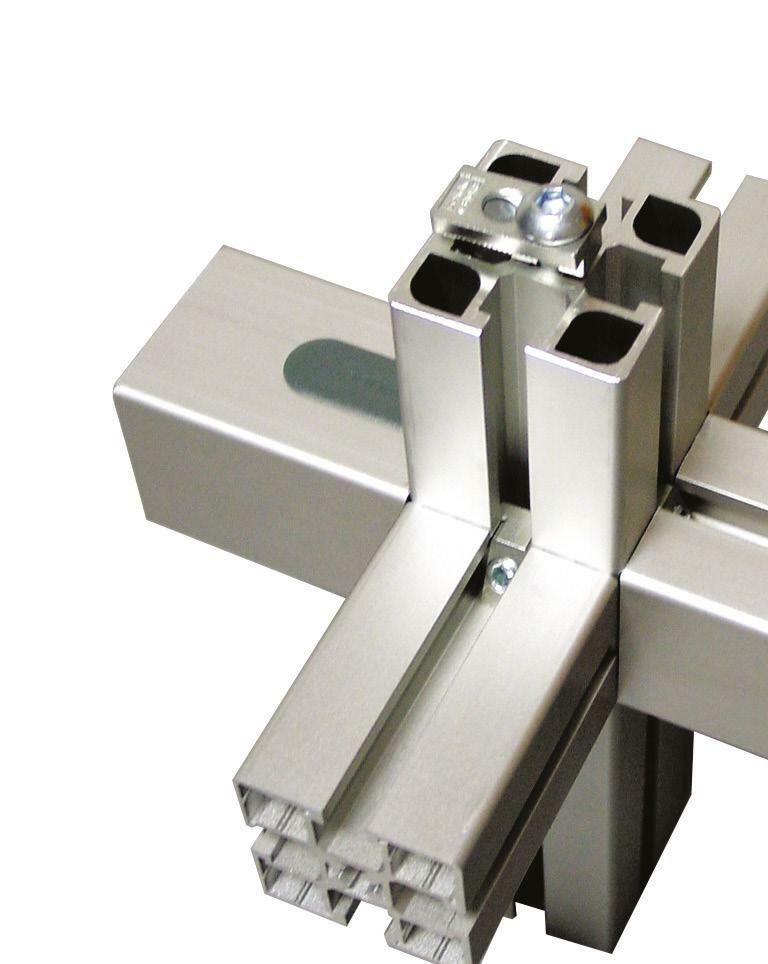
Multi-diaphragm&pulsation MiniTec, the ideal profile assembly solution
Liquid transfer low-pressure pulsation Feature: Diaphragm pumps T: 01256 365 605 | www.minitec.co.uk ›› customised enclosures ›› automated solutions ›› workstations ›› conveyors ›› tool cabinets ›› safety guards
for custom fabrication
For some applications or areas of use, the pressure pulsation can be signifi cantly reduced by interconnecting sev eral diaphragms in parallel, or by using dampeners. Why pressure pulsation should be avoided
turns into a pressure pulse (backup of cars). After all the cars have left the parking garage, it gets quiet until the end of the next movie (analogous to the suction stroke of the diaphragm pump).
Principle 1: Utilisation of multi-diaphragm pump technology For many years, the portfolio of proven KNF diaphragm pumps has included both a single-headed and a double-headed version – the socalled boxer-style pump. With this, the connecting rod drives two 180° phase-shifted diaphragms simulta neously (analogous to a two-cylinder

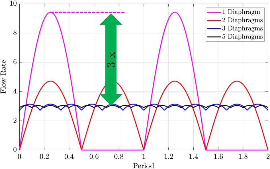
motor). While one diaphragm draws liquid from the suction line, the oth er diaphragm discharges it into the pressure line. This 180° phase-shift ed mode of operation leads to a pul sation-reduced transfer of the liquid. Figure 1 shows the instantaneous flow rate of multi-diaphragm pumps, such as double diaphragm pumps, compared to a single-headed pump. It demonstrates that flow rate peaks can be heavily reduced if several diaphragms are interconnected out of phase. From three diaphragms in use, peaks are reduced by a factor of three. Due to this reduction of the maximum instantaneous flow rate, the pressure pulsation caused by the hydraulic resistances inside the sys tem can be reduced significantly. Joining the two separate inlets and outlets of a double diaphragm pump is relatively costly and time consuming for customers, requires more space, and poses the risk of potential leakage at the respective fittings. This is why KNF took it one step further with its FP pump series and developed low-pulsation pumps with up to five phase-shifted pump diaphragms. The individual flow vol umes are joined inside the pumps. This way, customers strongly bene fit from having only one connection on the suction, as well as on the pressure side. This considerably simplifies handling for the custom er, reduces the space required, and eliminates additional tube connec tions.
Feature: Diaphragm pumps
Advantages of pumps with low-pressure pulsation Regardless of whether steady, lowpulsation liquid transfer is achieved by means of a multi-diaphragm pump or pulsation damper, it offers many distinctive advantages for the customer. For a desired flow rate, a pressure drop occurs that is up to 10 times lower. This is particularly important for media with higher viscosity, such as ink. At the same time, the power consumption of the pump motor is reduced, which means less heating of the motor. In addition, preventing high-pressure pulsation may reduce the formation of micro-bubbles. It may also prevent foaming, especially for liquids with low surface tension. The controllability of the pump is also significantly increased, as the flow rate is very linear to the speed and is independent of the customer system. Finally, the workload inside the pump is reduced and all components in the customer system are put under less stress, due to the reduced pressure pulsation. This can increase the service life of the pump and other system components. As an additional effect, the vibration of the tubes is reduced, which contributes to noise reduction. To learn more about low-pulsation liquid diaphragm pumps and how they may fit your application, contact KNF’s experts, who can offer you a solution that can be specifically tai lored to your needs.
Principle 2: Utilisation of pulsation dampers and hydraulic accumulators
Another approach to reducing the pressure pulsation of a single-headed diaphragm pump is the use of a socalled pulsation damper that is usu ally mounted in the fluid system on the pressure side of the pump. This approach has also been successful ly used by KNF for years in various flow and pressure rates. As already mentioned in the context of the boxer version, however, additional connec tions may lead to potential leakage points. Increased space requirements associated with the use of a pulsation damper are not always ensured in the customer’s system. In addition, the installation of a pulsation damper is associated with additional costs for the user. In response to current market needs, KNF developed the world’s first liq uid diaphragm pump featuring an integrated pulsation damper within the pump head, on both the suction and pressure sides. This feat was accomplished in a very short time, using state-of-the-art simulation and manufacturing tools. When the pump diaphragm moves downwards during suction, it not only draws liquid from the suction line, but also from the pul sation damper on the suction side. This only works because the damp er diaphragm can move downward, due to the negative pressure. When the pump diaphragm is expelled, the liquid in the suction line can refill the damping chamber on the suction side. This can be easily recognised by the upward moving damper dia phragm. This way, an almost contin uous volume flow is achieved in the suction line. On the pressure side, the pulsation damper absorbs part of the volume expelled by the pump. This can be easily seen from the upward moving damper diaphragm. If the pump dia phragm now starts sucking in again, the volume stored in the damper on the pressure side is released to the pres sure line (the damper diaphragm on the pressure side moves downward). Thus, a continuous volume flow inside the tube is also achieved on the pressure side. Thanks to the low-volume flow fluctuations in the tubes, the pressure pulsation on the suction and pressure side is minimal, due to the integrated dampers. This provides the customer with a low-pulsation liquid diaphragm pump that, except for back pressure, operates virtually independently of their system. Depending on the pump type and operating point, the pulsation can be reduced by up to a factor of 20. Furthermore, additional interfaces are eliminated for the customer.
https://knf.com/en/uk
Figure 1: Simplified representation of liquid discharge by diaphragm pumps without back pressure. The maximum instantaneous flow rate of a single-headed pump is three times larger than the nominal flow rate. The more diaphragms are interconnected in parallel, the smaller this superelevation becomes
26 dpaonthenet.net
Try free at ist.org.uk/worksmarter The Data Driven Solution to Spring Design & Validation SPRING CALCULATOR PROFESSIONAL +44robotics.kawasaki.cominfo@kawasakirobotuk.com(0)1925713000 Multi-skilled high performers.... Kawasaki robots deliver high-performance, reliably and consistantly, for the widest range of manufacturing applications. From high-speed precision assembly to taking the strain of handling ultra heavy products, there are Kawasaki robots world-wide helping businesses achieve their maximum potential. Contact us now to discover more about practical and affordable leasing terms on all new Kawasaki robots. Kawasaki Robotics (UK) Ltd


The Juno space probe uses over 60 different springs to perform three major functions: to open the doors to the solar panels, to guarantee the doors remain latched during flight, and to position the arms it uses to measure Jupiter’s structure. Of course, it’s not just in space probes where projects require springs with very specific requirements. Here, Simon Ward, Technical Manager at TFC, answers some questions about designing wave springs.
TFC’s engineers also use a ‘No-ToolingwaveDesigningsprings: your answeredquestions
28 dpaonthenet.net
How are wave manufactured?springs
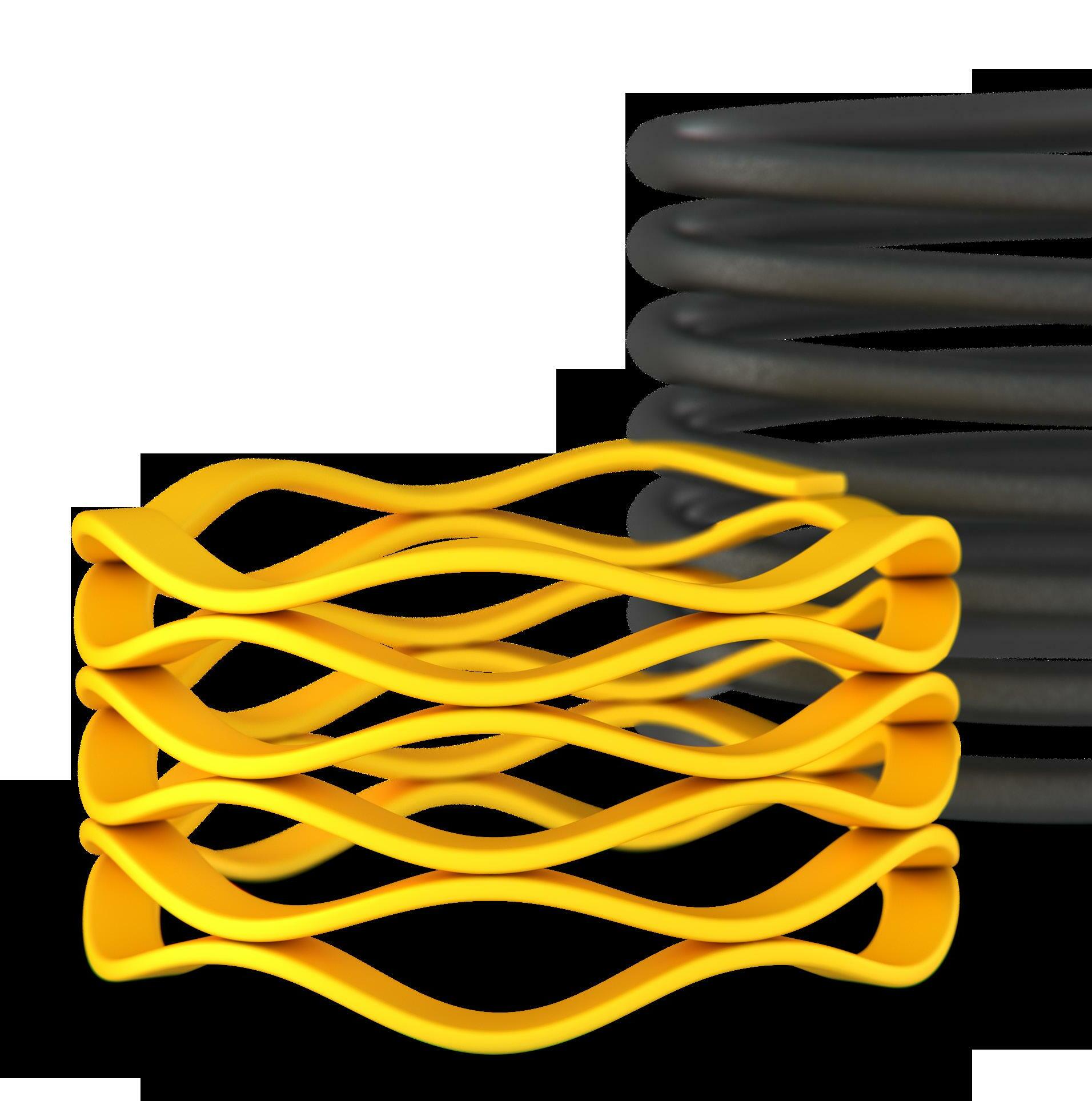
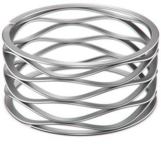
What is a wave spring?
Feature: Wave springs
An alternative to the traditional coil spring, wave springs are produced from pre-hardened flat wire and formed to a precise diameter with a sinusoidal wave form. When loaded, this means that they can act like a spring by deflecting and providing a preload between two sur faces. Therefore, wave springs can be used to preload seals or bearings, absorb shock, and compensate for dimensional variations and thermal tolerances.
Wave springs are manufactured by coil ing flat wire on edge, known as ‘edge winding’. This process increases design flexibility and reduces the lead time for bespoke designs. It also ensures that prototype batches are manufactured in the same way as production parts, so any prototype or preproduction testing can be considered valuable production data. With edge winding, only the required flat wire material is coiled, eliminating mate rial waste. The circular-grain metallurgy also improves strength, and the cold roll ing process causes metal grains to elon gate and lock together, which provides good mechanical properties.
What materials can I use? There are several options, and your choice is often determined by the re quired temperature and corrosion resist ance. Common materials include 302 and 316 stainless steel, which can withstand temperatures of up to 200ºC. For appli cations with elevated temperatures, 17-7
Ph/C stainless steel has a maximum rec ommended temperature of 343ºC. For extremely low temperatures, like those found in cryogenic systems, 300 series stainless steels or nickel alloys are gener ally Corrosionpreferred.can also cause springs to fail, so designers will consider whether the environment is corrosive before specifying a material. 316 stainless steel offers high corrosion resistance because of its molyb denum content and is often used in sea water applications. If the environment is highly corrosive, high-performance alloys like Inconel and Elgiloy are specifically de signed for such a surrounding.
Feature: Wave springs dpaonthenet.net 29
Cost’ process, which reduces production times and allows any modifications, at the prototype stage, to be made quickly and easily. Therefore, this process can help provide an economical custom option in weeks, not months. What types of wave springs are there? There are five main types of wave springs, each with distinct features that determine spring performance under load. These in clude Crest-to-Crest wave springs, which have a multi-turn flat wire design and are suitable for low to medium forces. For low deflections, you can use overlap and gaptype wave springs, whereas Nested and Wavo springs are typically used for high er forces. Finally, linear springs, another in the wave spring family, are formed in a straight line. Can I change the spring rate? You can change the thickness of your wire and the waveform to achieve the required spring rate for any given application. Most wave springs are manufactured using car bon spring steel or 17-7 PH as a standard material, but the choice is up to you.
About the author: Simon Ward is Technical Manager at TFC.
When designing a wave spring, TFC ac counts for dimensional constraints, the desired load/deflection characteristics, cycle life demand, and operating environ ments and temperatures. Each of these factors will determine your choice of ma terials and, therefore, the final design of the TFC’sspring.engineers are on hand to design custom wave springs for all applications. Visit https://www.tfc.eu.com/ or call 01435 866011 to speak to a member of its design team, who will gladly work with you.
You can also alter the number of waves per turn and the number of turns. For in stance, if you need a light-duty spring for a smaller application, you can use thin wire or remove waves from your design. Single turns are best suited for applications with low to medium forces. For high force and precision, manufacturers can consider a nested wave spring with multiple turns. What sizes are available? Wave springs are available in a vast num ber of diameters. The smallest off-theshelf wave spring is typically around 5mm – and, at the other end, bespoke sizes can be manufactured up to about 3m. If a designer can’t find an off-the-shelf size that suits their application, they can order a custom solution that meets their exact requirements.


Safety-critical spring failure in the aerospace sector
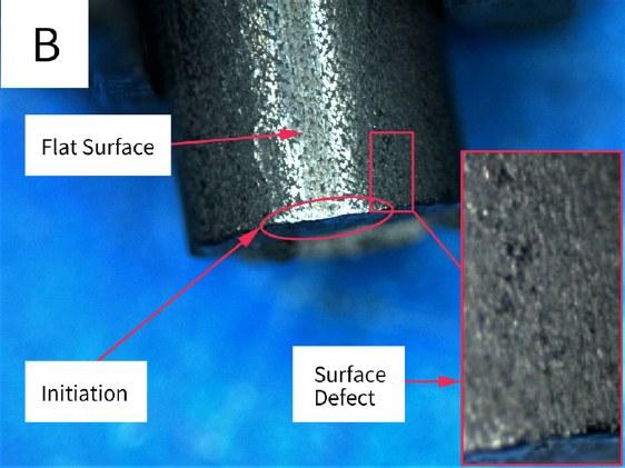
Figure 1: Optimal images taken of the fracture face and surrounding wire of one of the fractured springs
30
Feature: Aerospace
This article will look at an extension spring, manufactured from stainless steel wire, which failed during fatigue testing. The spring was part of a safe ty-critical system used in the control panel of a plane. The end user sent several springs for fatigue testing, half of which were failing the fatigue requirements. The failures were all located in the same position, within the hook of the spring. Multiple failed samples were supplied for evidence, along with an unfractured sample for comparison. Our standard failure analysis consists of four main stages: visual examina tion, optical metallography, hardness test and scanning electron micro scope and EDX analysis. Figure 1 shows images taken during the visual examination. Image A depicts the fracture face from one of the fractured springs, showing a typical fatigue failure. Initiating from the inside hook position (region of highest stress in the hook), the fatigue crack propagat ed roughly halfway through the wire, concluding in a final ductile overload. Examination of the fracture faces not ed multiple suspected initiations coa lescing into one propagation. Image B shows the surface of the wire at the in side hook position. The surface of the wire was damaged during operation, most likely due to wear. A closer ex amination of the wire surface showed a suspected longitudinal defect, away from the flattened region on one of the fractured springs. However, damage was also noted at the inside hook po sition on the spring which did not fail, indicating that there could be another reason for the Microstructuralfailure.andhardness evalua tion of the springs were as expected for this grade of material (ASTM A313 grade 631) and showed no significant microstructural or hardness variations between the broken and unbroken samples. It was therefore concluded that there were no issues with the structure of the material. However, during the microstructural exami nation, surface defects were seen throughout the circumference of the Thewire.majority of stainless steel grades do not have any limits on the depth of surface defects, beyond being visually free from pits, seams etc. Therefore, In the aerospace sector, springs are everywhere. They’re in the seats and luggage bins of commercial planes, the control panels of jet fighters, and the antenna of satellites. Although there are hundreds of different spring shapes and designs flying above our heads every day, they all have something in common; they can fail. Although a lot of springs might not be considered “safety critical” in the aerospace sector, failure – especially systemic failures – is not acceptable. Would you feel safe on a plane if there were broken components in the cabin? springs dpaonthenet.net


Providinglife.
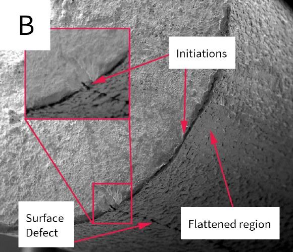
About the author: Dr Conor McCaughey is a Metallurgist at the Institute of Spring Technology. although defects were seen through out the circumference, none of them was deemed to be beyond what is ex pected for this grade of material. Finally, the failed springs were im aged in a SEM – some of the images taken can be seen in Figure 2. Image A shows the initiation of one of the failures. This was in the flattened re gion on the inside hook position – as expected, based on the information gathered so far. However, although longitudinal striations, typical of wear, can be seen in the flattened region, the initiation points are located where the damage on the surface seems more comparable to the defects seen throughout the surface of the wire. This was also the case for one of the other failures examined, but not for the last failure. This fracture face showed that an initiation took place away from the flattened inside hook position at a longitudinal defect, seen in the visual examination. These ob servations indicate that the failure was not ultimately due to the wear and flattening of the inside hook position, but due to surface defects inherent to the wire. EDX analysis showed no evidence that corrosion had been a factor in the failure. With the evidence compiled in the report, it would be easy to conclude that the failure was caused by surface defects, accelerated by wear, and leave it at that. This, however, isn’t very helpful for our customer, who is left knowing the problem but not how to fix it. This is where it pays to have an expert in a component perform the failure analysis. We can make several recommenda tions as to how this could be reme died. Although there are no limits for surface defects within the standard for this grade, these can be request ed by the customer. Our knowledge of dynamic grades allowed us to give a reasonable recommendation for the depth of surface defects. This should increase the fatigue life, but also be achievable by a wire manufacturer. Beyond this, we can also inform the customer that although the predic tions for the fatigue life of the spring were in excess of what was required, this is only for the body of the spring, not the hooks. The hooks of extension springs are under different stresses from the body of the spring: bending and torsional stresses in the hooks compared to purely torsional stresses in the body. Depending on the design of the spring and hooks, the stress es in the hooks can exceed those on the spring, reducing the fatigue life of the component. We can calculate the stresses in the hooks and give a predicted fatigue life, based on exper imental data produced in our lab. This would allow us to look at the design of the hooks and possibly suggest rede signs, if the surrounding fixtures allow.
a thorough and accurate service not only determines why this failure occurred, but also gives reas surance that future failures can be eliminated. This gives the customer the confidence to put these springs into aircraft, where hundreds of lives could be reliant on a spring not failing prematurely. https://www.ist.org.uk/ SEM images of two of the fracture faces examined
Feature: Aerospace springs Figure 2:
Finally, we also recommended shot peening the springs. Shot peening will impart beneficial residual stresses into the surface of the spring, as well as reducing the defects seen on the sur face. Shot peening is not usually done on extension springs, as the benefit to the body of the spring is usually mini mal. However, in this case, where the failure is occurring in the hook, shot peening should increase the fatigue


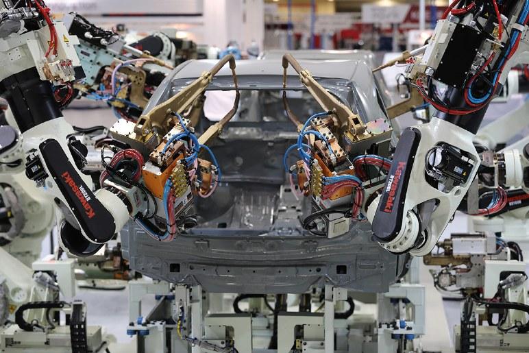
While there is a lot to be optimistic about on the topic of robotic automation and the future of work, it can be hard to spot a positive headline when it comes to the way that robots are portrayed by the national press. Dramatic headlines have always pulled audiences, and this is certainly the case when it comes to telling the story of robots in manufacturing. Rather than accounts highlighting the proven bene fits that robots have delivered worldwide for both companies and their workers, it is more common to see negative reports with headlines such as ‘Robots to replace up to 20 million factory jobs by 2030’, ‘Au tomation could replace 1.5 million jobs’ and ‘When robots steal our jobs’. While such headlines may grab public at tention, they only tell half of the story, omit ting several key facts that should be also included, to add context and highlight the growing necessity for robots to be intro duced to the nation’s factory floors. Foremost among these is the simple fact that there is often nobody to fill the jobs in question. A perception of manufacturing as dull, dirty and dangerous has resulted in a growing skills shortage that is having a major impact on the ability of manufac turing companies to carry out work and win new projects. Prior to the COVID-19 global pandemic, 33 percent of vacancies in the UK were reflected as hard to fill, due to a lack of qualifications, experience and skills. According to a skills shortages UK 2019/20 report by Luminate Prospects, 106,000 vacancies were recorded as diffi cult to fill, with 79,000 of those due to skills
Robotic automation has the potential to transform the future of work, taking the strain off employees and providing them with a more rewarding working environment. Julian Ware, UK & Ireland Sales Manager of ABB Robotics, explains why it’s time to change the narrative when it comes to robots and jobs.
Asshortages.thisshortage places a premium on the available skilled workers, some compa nies are paying higher prices in inflated salaries to retain staff and ensure that their business can stay productive. Training employees hired at a lesser level than envi sioned and the escalating costs of recruit ment fees are other factors that also need to be considered.
Setting the record straight on robotic automation
Supplement: Smart manufacturing
32 dpaonthenet.net

Robotic automation is not all doom and gloom, but is a helping hand, enabling manufacturers and their employees to fulfil their potential.
Time to tell a new story
Supplement: Smart manufacturing
Using ABB’s YuMi cobot has enabled Italian manufacturer, Anodica, to boost productivity by 20 percent, while giving its workers moreergonomicinteresting,work These factors all build a strong case for robotic automation. The expanding capa bilities of robots – including dexterity, flex ibility, adaptability and agility – is opening new opportunities for them to be deployed across a growing raft of manufacturing operations. As robots become increasing ly able to collaborate safely with humans, new opportunities are being created for companies to achieve new levels of pro ductivity and performance, by combining the inherent skills and intelligence of their manual workforces with the fast, flexible and efficient performance of robots. One example of this is Italian metal com ponents manufacturer, Azeta. Specialising in the manufacture of hydraulics compo nents, Azeta installed ABB’s YuMi collab orative robot to support its employees with carrying out more challenging tasks, as well as providing production efficiency. The robot released employees from per forming tedious repetitive tasks, eliminat ed ergonomic risks, and offered them the opportunity to grow within the business and contribute more of their knowledge to MostAzeta.tellingly, feedback from those on the company’s production line was highly positive, with employees asking the man agement to invest in more robots. This alone was a great demonstration of the impact that robotic automation can have on employees. It helped the company to lessen its Occupational Repetitive Actions (OCRA) index on various workstations across its manufacturing line. Far from being a barrier to job creation, ro botic automation is a way for companies to help their workforces to be more pro ductive and to create new job roles that will push business forward in other areas. The ability of robots to be adapted to han dle different tasks enables organisations to be more proactive, plan ahead, and be able to cope with any external or internal crisis. The ‘dull, dirty and dangerous’ jobs are immediately taken care of, 24 hours a day, seven days a week – with no health or mental risks. This liberates the employ ees to extend their careers at that compa ny, as they are performing more fulfilling, creative, and mentally stimulating jobs. Overall, this increases the dependence on people and opens up opportunities for Moreover,employees.the improvements in produc tivity, efficiency and competitiveness that can be achieved using robots can also enable companies to grow their opera tions, resulting in additional employment to fill new roles needed to support growth – from sales and order processing through to delivery.
https://new.abb.com/products/robotics
straight dpaonthenet.net 33
Robots can help to move people away from having to work on dirty, dull and dangerous tasks and, instead, work in more rewarding roles
About the author: Julian commencedWare his engineering career as a technical apprentice, completing an HND with Distinction at De Montfort University in Bedford, as part of this role. After completing his apprenticeship, he joined Atlas Converting Equipment Ltd, where he progressed through various engineering roles and finally into a technical sales role. After 18 years with Atlas, he then moved to SalesasupABB2018,JaguarAccountincludingapositionsengineeringheAutomationRockwellwhereheldtwodifferentsalesoveralmost10-yearperiod,GlobalManagerforLandRover.InJulianmovedtoRoboticstotakehiscurrentposition,theUK&IrelandManager.
For UK manufacturers, the truth is that a failure to join their international compet itors on the journey to automation will leave them struggling to keep up. In this scenario, it will be the failure to automate that will result in lost employment. It is also necessary to consider the impact of the COVID-19 pandemic. With many manufacturers hit hard by the combined impact of repeated lockdowns, staff sick ness and the requirements for social dis tancing on factory and warehouse floors, there is a growing interest in how robots can help. In a survey of 250 large and small UK businesses carried out by ABB, 81 percent of respondents said they are likely to introduce (or increase the use of) robotics and automation in the workplace in the near future. ABB believes that robots will not replace humans in jobs, but will, instead, provide an augmentation to human labour. When combined with well-designed occupa tional training and staff development, robots can provide employees with the opportunity to develop their skills and engage in better, more rewarding tasks.


These solutions enabled companies to turn analytics into flexible operations which were able to respond and adapt quickly to the new working conditions and legislation, such as social distanc ing, self-isolating, and ill health. Those companies which had reimagined their operations and understood the value of forecasting were able to address poten tial disruptions and challenges before they occurred. Customising the future – the new revolution Once manufacturers introduced con nected devices, data analytics and arti
Before COVID-19, the uptake of ad vanced manufacturing technologies and automation was gaining momentum, but many manufacturers were still address ing their digital strategy and how to transform their operations into the smart factory of the future. When the virus spread worldwide last year, it accelerat ed the adoption of digital solutions, as more manufacturers realised the impor tance of innovative technologies, such as digital twins, to increase end-to-end supply chain transparency.
34 dpaonthenet.net
revolution.Supplement:
ficial intelligence, the big question was: what’s next? The journey does not sim ply end there. Each new stage of the Industrial Revolution represents an ad vancement in the manufacturing process and the ever-evolving changes to the way we think and work in the industry.
Accelerate digital transformation with Industry 5.0
The First Industrial Revolution brought the United Kingdom into an era of technology and productivity. Today, Industry 4.0 focuses on the interconnectedness of machines, to optimise production processes on the factory floor. Now, with the rise of digital transformation and remote monitoring solutions which have been integrated as a result of the pandemic, Industry 4.0 is already underway.
Industry 5.0 will continue to focus on the collaboration between humans and machines, but, specifically, on the added value workers will provide when robots are handling the more arduous manual tasks. Increasing automation will provide new opportunities for both the existing and future workforce, as we enter a new phase of mass-customisa tion production that is more focused on agility and responsiveness. To prepare for this, companies will need to identify how they can upskill and reskill workers. This may involve training on new software and systems to ensure employ ees are equipped with the right skills to develop, manage and maintain machines.
Phil Hadfield, UK Managing Director at Rockwell Automation, discusses the next steps for manufacturers as they move towards the fifth industrial Smart manufacturing
The role of humans There is no doubt that automation will have an impact on employment in the coming years. This has raised concerns that ma chines will replace workers’ jobs, but In dustry 5.0 brings attention to the need for a ‘human touch’ revolution, whereby workers
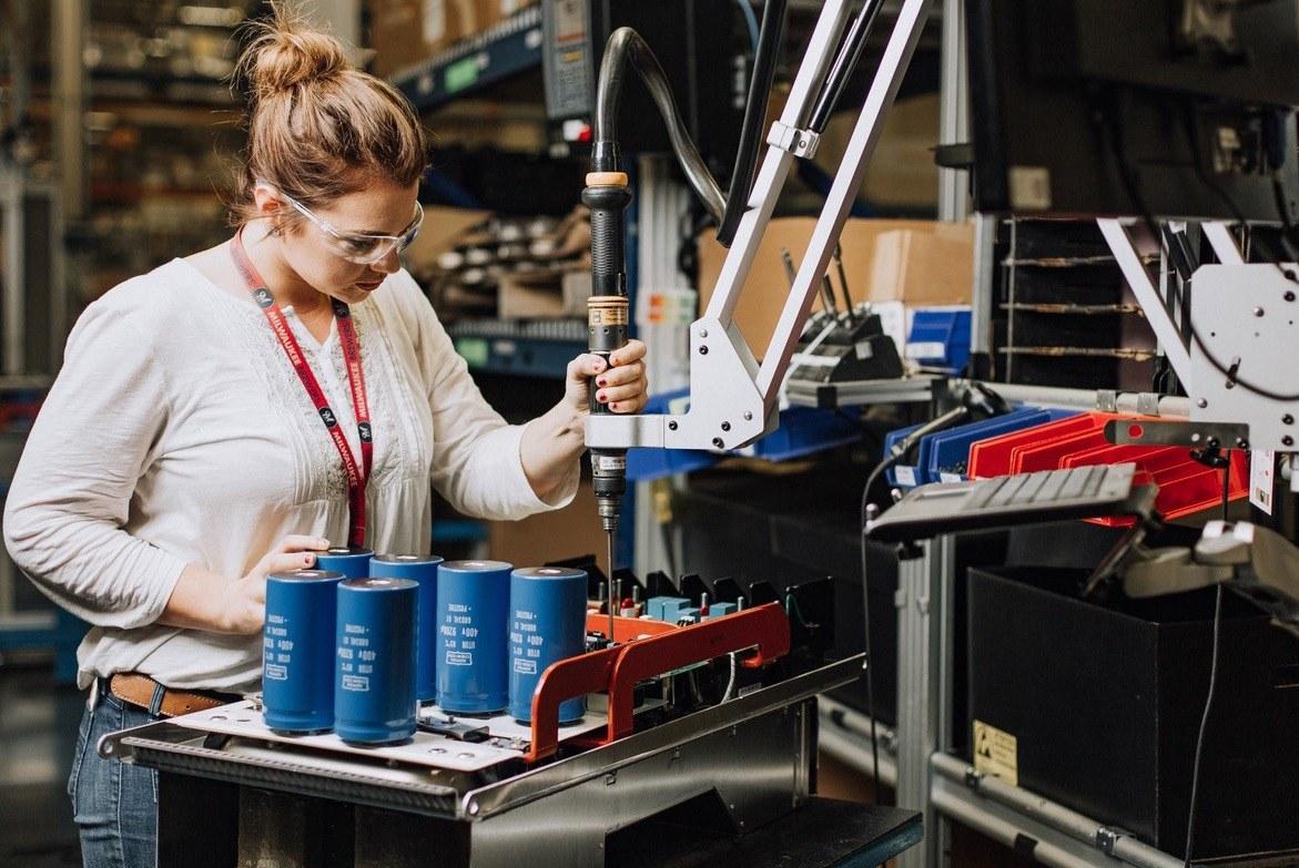

Combining intelligent systems with existing workflows can better leverage human creativity and brainpower. The upcoming Industry 5.0 would therefore focus on the collaboration of humans and machines to deliver individualised products, services and customers experience. Thus, human involvement would be intellectual rather than physical. A career in STEM With technology at its forefront, many manufacturers question what the future workforce will look like. The rise in artificial intelligence (AI)-powered automated tasks and virtual reality learning means the upcoming workforce will need to keep up with this growth. The World Economic Forum in its 2018 report, ‘The Future of Jobs’, said: “The skill sets required in both old and new occupations will change in most industries and transform how and where people work.”
Therefore, to prepare for Industry 5.0, we must train the existing workforce to understand and collaborate with machines – and we must also prepare the future workforce to learn and grow alongside future technologies which will reshape the global manufacturing landscape.
The Government Office for Science’s foresight project, ‘Technology and Innovation Futures’, identifies technological areas that could give the UK a competitive edge. As part of the project, the ‘UK Growth Opportunities for the 2020s’ report was filed, which discusses how the increasing demand for personalised products will call for new manufacturing technologies, such as rapid prototyping, 3D printing, and smart infrastructure. Adopting this be spoke manufacturing-on-demand model would enable the UK to provide new opportunities for local, niche manufacturing, which continues to innovate in the design of products and services.
Automation with Drive www.keb.co.uk KEB (UK) Ltd. 5 Morris Close Park Farm Industrial Estate Wellingborough NN8 6XF Tel: 01933 402220 E-Mail: info@keb.co.uk SMART AND DIGITAL AUTOMATION MachineryPackaging SystemsTheatre ProcessingMetal MachineryTextile EngineeringProcess Lift Escalators& logisticsIntra- MachineryPlastics e-mobility AutomotiveWood Working Wind Power
Technology is a vital component of the future – and it’s important that we pre pare the children of today by learning the underlying principles. Giving them opportunities to create and innovate, through tools such as computer pro gramming, will be an important aspect of ensuring the future workforce has a strong skill set in STEM. New categories of jobs will emerge, which will also help create the economic surpluses that will enable societies to address the workforce transitions that are likely to happen regardless, due to the retirement of the baby boomer generation. So, in the coming years, there will be increasing demand for data analysts and scientists, machine learning engineers, and software developers – amongst other occupations.
About the author: Phil Hadfield is UK Managing Director at Rockwell Automation, a provider of industrial automation and digital transformation. He has been with the company for more than 16 years, having begun as a Drives Commercial Engineer, and subsequently moving up the ladder to his current position.
Supplement: Smart manufacturing dpaonthenet.net 35
SPECIALISING IN SOLUTIONS will add a particular creativity and flair to personalise products for customers. Thus, digitalisation would not make humans in the manufacturing sector obso lete, but, rather, jobs will change and adapt to meet the new production needs.
To find out more about how you can provide lifelong learning to empower your workforce, and how to inspire students to pursue a career in STEM, visit: our-community/stem-education.htmlhttps://www.rockwellautomation.com/en-gb/company/about-us/


From small to large – HandlingTech’s modular robot cells are an efficient cornerstone for economical automated production. (Source: HandlingTech)
“Innovative automation with a system”: for HandlingTech Automations-Systeme GmbH, the slogan says it all. Founded in 1994 as an automation newcomer, Managing Director Jörg Hutzel’s, fami ly-owned company has developed into a veritable robotics player. Today, the automation specialist from Steinen bronn, south of Stuttgart, is well known in robot automation and specialises in creating customer-specific solutions based on its standard robot cells. “Our roots are in special machine con struction. Customers simply expect problem-solving solutions from us,” emphasises Gregor Großhauser, who is responsible for sales and marketing at HandlingTech’sHandlingTech. systems enable full automation of industrial process se quences, as either standalone ma chines or as machine adaptations. The modular systems can be easily and economically adapted to customers’ machine-specific requirements. From standard to highly complex systems, with supplementary processes and au tomated parts feeds, there are virtually no limits. Proven partnership For its automation components, the company relies on external partners who provide them with time-tested, future-proof solutions and systems. Murrelektronik GmbH has been Han dlingTech’s proven partner for many Marcoyears. Balzuweit, HandlingTech’s Elec trical Designer, says: “The collaboration started by using Murrelektronik’s Exact distribution boxes to bring data from in network technology: unmanagedMurrelektronik’sswitches
Automation specialist, HandlingTech, develops and implements modern modular handling solutions for industrial manufacturing sites. In its sophisticated robot cells, Murrelektronik’s unmanaged 8-port and 16-port switches make the networking of Ethernet nodes uncomplicated and compact.
36 Supplement:dpaonthenet.netSmart manufacturing Excellence
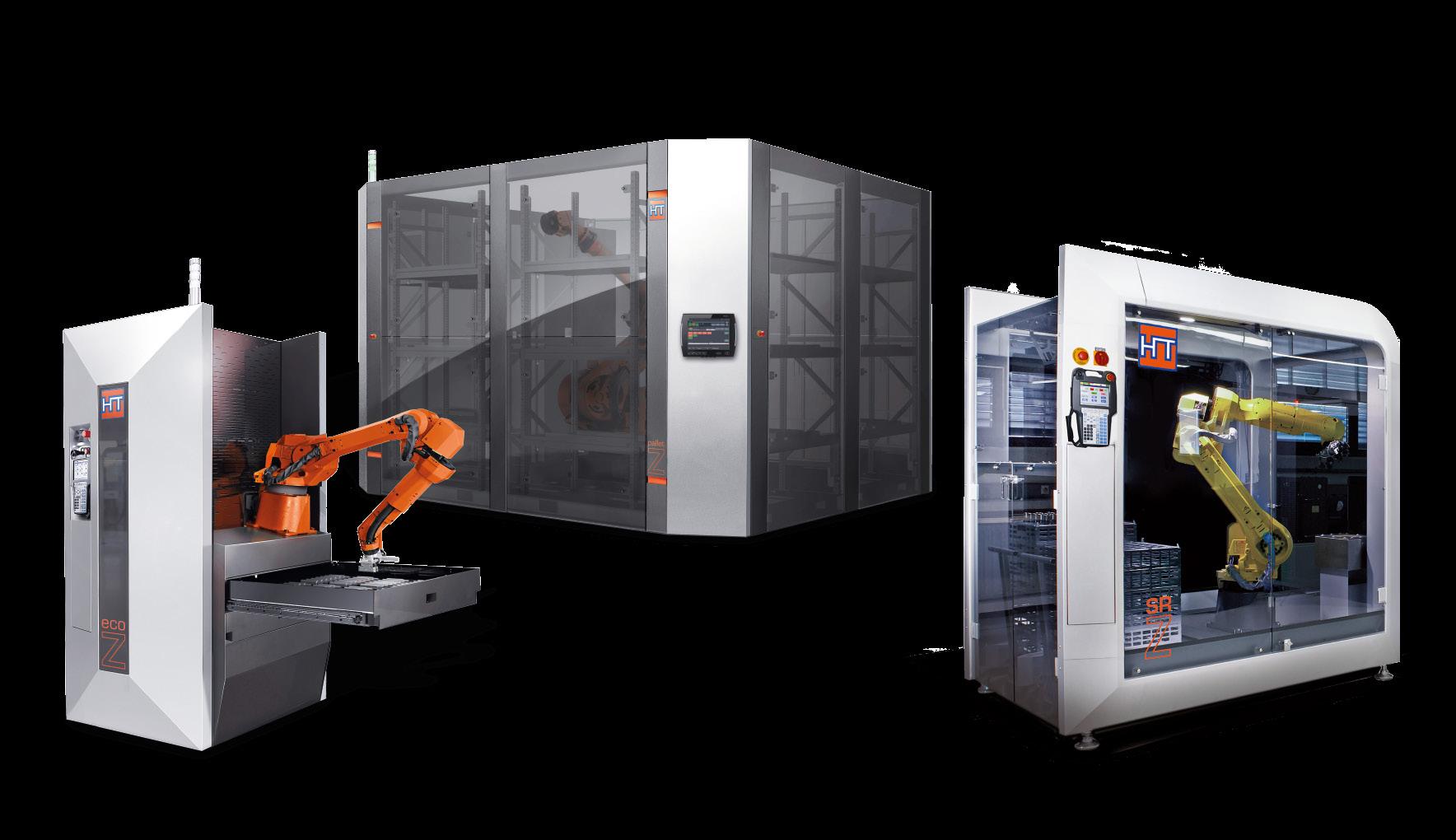
PRECISION MOTION CONTROL Custom engineered motion systems Servo motors & drives Synchronous
As an advanced motion control technology distributor and manufacturer, Mclennan supplies and fully supports a wide range of precision motion control components from its distribution partners - and also has the capability to combine these products with its own design and build service for bespoke and turn-key motion sub-systems - for applications across industry and research.
and
Official
motors Stepper motors & drives Feedback devices Gearboxes Motion controllers & software Mechanical sales@mclennan.co.ukcomponents www.mclennan.co.uk +44 (0)1252 531444
support for the
Supplement:
Henning Schultz, Electrician and Elec trical Designer in the production depart ment at HandlingTech, was sold on Xel ity switches at first sight: “The compact design of the Xelity 8 port is super. Their small size allows them to fit easily next to a power supply, contactor or relay, without having to create extra space on the DIN rail or in the cable ducts. I also find the push-in terminals very practi cal, as many competitors still have an additional plug with screw caps, which complicates the connection. Size, feel, function and price of the Xelity switches make them a well-rounded product.” Smart manufacturing HandlingTech equips its standard robot cells with two Xelity switches. (Source: Murrelektronik) stocking distributor technical UK & Ireland AC
Call us or visit our website for more information Mclennan is your perfect partner in your quest for the right miniature electric motor. We can help you specify and integrate the exceptional range of Portescap motors into your next project or design. Portescap offer a rapid prototype service to support new projects and at Mclennan we cover a range of Portescap products from stock, and support OEM customers with integrated solutions and Kanban delivery agreements. Talk to us...
field sensors into the control cabinet. Their implementation was followed by various power supplies – currently, we are using Emparro switch-mode power supplies. Most recently, HandlingTech made the decision to use Murrelektron ik products for the I/O distributors in the control cabinet. We selected Cube20S I/O systems, which combine digital in puts and outputs into one cell and bring them back to the bus node. We have also made use of Murrelektronik’s ex tensive range of connection technology products.” Compact and affordable Since the beginning of 2019, Murrele ktronik switches have been installed in HandlingTech’s standard robot cells. The “door openers” were the Xelity 8 port unmanaged switches. Push-in ter minals for the power connection simpli fy the wiring of the individual switches. The devices prioritise PROFINET proto cols and, thus, prefer PROFINET data over Ethernet data. Xelity switches can transfer data packets at speeds of up to 100Mbit/s.


The industrial PC, the robot, and the safe ty and remote maintenance systems are connected to the switch via an Ethernet TCP/IP interface on the outside of the control cabinet, so that it does not have to be opened for service work. This means that the majority of the ports are occupied, leaving one or two ports as a reserve, for measuring tasks in the cell. Eight and eight are not sixteen Xelity switches can reach their communi cation limits when large amounts of data are involved. This is where Murrelektron ik’s Tree16 TX unmanaged switch comes into play. The 16-port unmanaged switch has two Gigabit Ethernet uplink ports and 14 Fast Ethernet downlink ports. Dennis Zimmer, Murrelektronik’s Product Manager – Switches, explains the differ ence between these 16-port switches and competitor’s solutions, which consist of two interconnected 8-port switches: “You would think that eight and eight are sixteen. But that is definitely not the case in this instance. The connection between the two 8-port switches is not designed to handle large amounts of data. Our device is a pure 16-port switch with a matching controller chip. The composite switches may be less expensive, but our 16-port switch is reliable and has the necessary power.” Marco Balzuweit of HandlingTech adds, “We haven’t had any failures with Murrelektronik’s 16-port switches.”
When handling large amounts of data, Murrelektronik’s 16-port switches are the way to go. (Source: Murrelektronik)
The camera data is processed autono mously on a separate computer. In this system, the 16-port switches are respon sible for the communication between the robot systems. The two-gigabit ports en sure communication with the higher-level controller, while the remaining 100Mbit ports collect data from the various partici pants in the cell. Strong also in support Henning Schultz also sees Murrelektron ik as an asset in another important area: support. “If I have a technical question or a problem, I can get a product engineer or an application engineer on the phone quickly. In special machine construction, where orders are also won via delivery time, [an] immediate response is impor tant. When I need quick help, I get it at Murrelektronik. In addition, Murrelektronik only releases market-ready products.”
https://www.murrelektronik.uk/gb/
38 Supplement:dpaonthenet.netSmart manufacturing
Murrelektronik Product Manager, Dennis Zimmer, responds: “When a product is close to completion, we take it to custom ers to get their feedback. We presented the Xelity switch to HandlingTech in ad vance. Our customers know the product requirements best and tell us what is good and where something can be improved. It’s kind of a joint development with the customers.”
Especially in special machine solutions, where several large robot and processing modules are networked together, there are always cases where the Gigabit ports on the unmanaged 16-port switches are needed. One example is a large system for machining shafts, where a machine tool is positioned between two robot cells from TheHandlingTech.firstrobot station is tasked with re moving the workpieces from a grid box and loading the machine tool. The work pieces are fed to the system via a grid box, in which the shafts are randomly placed. The robot uses path planning, based on a point cloud, to grip the components. A point cloud is generated based on data from a vision system above the grid box, to calculate the best approach point for the robot gripper. The robot, equipped with an interchangeable gripper system, picks up the component with a magnet ic gripper and deposits it on a clipboard, where it is aligned. It then loads the tool to machine the part. The robot in the sub sequent cell unloads the machined shafts from the tool and packs the parts directly into cartons with a blister layer.
Two switches per system Henning Schultz says, “We provide two Xel ity switches standard for each robot cell, in order to separate Ethernet and PROFINET whenever possible. Even if only four or five ports are occupied, in the highest expan sion stage, we need all of them. It is also important for us, as well as for the control cabinet builders, to have a certain design standard. Murrelektronik switches are now part of almost every installation of ours.”
Not only are new plants equipped with the Xelity switches, but older ones are as well, during retrofitting. Many older plants [that] have Ethernet as the standard are not yet equipped with a bus system. Therefore, HandlingTech’s electrical engineers have repeatedly integrated these switches dur ing retrofits, at the customer’s request.
Nancy Locher, Murrelektronik Sales Engi neer, adds: “In a retrofit, space is often the limiting factor. The compactness of Xelity switches is a big advantage here.”

contribution
Reflex Photonics has benefited from support from the European Space Agency ARTES Scylight program with financial contribution from the Canadian Space Agency to pursue the development of advanced, high-speed, digital intrasatellite optical fibre communication modules.
Building on the recognized robustness inherent in the design of Reflex Photonics’ optical modules, the SpaceABLE®28 line will provide radiation resistant optical interconnect modules tested and qualified for use in harsh space environment.
advertiseToherecontact QuenaultAndrew on 01732 359990 or email andrew.quenault@imlgroup.co.uk Buyers Guide:Geared Motors – 12mm to 90mm dia Offer OuranddriveSolutionsEconomicalTrulytoapplicationproblemswithacomprehensiverangeof3vto24vDCmotors,gearedmotorsaccessories.Hybridsolutionsalsoavailableatmoderatecost.productsarewidelyusedinindustry,education and R&d markets, with some of the following as typical applications. Robotics, laboratory equipment, surveillance cameras, slot machines, shop displays, vehicle equipment, telecoms equipment,lighting and ventilation control. Locking mechanisims, machinery activators, shop displays etc etc. MFA/Como Felderland Lane, Worth, Deal, Kent CT14 0BT Tel: 01304 612132 Email: info@mfacomo.com Web: www.mfacomodrills.com Displays Review Display Systems Ltd 01959 563345 www.review-displays.co.ukDisplay systems Review Display Systems Ltd 01959 563345 www.review-displays.co.ukIndustrial Pc’s Display systems Review Display Systems Ltd 01959 563345 www.review-displays.co.ukTouchscreensIndustrialPc’sDisplaysystems To hereadvertisecontact QuenaultAndrew on 35999001732 or emailimlgroup.co.ukandrew.quenault@ Springs PRESSINGSMANUFACTURERSOFSPRINGS•WIREFORMS T: 0118 978 6573 F: 0118 989 4434 E:www.simpsonsprings.co.uksales@simpsonsprings.co.uk Batteries & Chargers datafocus Visit the website and subscribe to our newsletter Website: http://www.connectivity4ir.co.uk/ Twitter: @connectivity4IR Everything you need to know about how to get the best out of Industry 4.0 and the Industrial Internet of Things Understanding the Fourth Industrial Revolution Reflex Photonics awarded multimillion-dollar contract for intrasatellite optical interconnect for advanced, high-throughput communication satellites. SpaceABLE optical modules developed for ARTES Scylight program
dpaonthenet.net 39 advertiseToherecontact QuenaultAndrew on 01732 359990 or email andrew.quenault@imlgroup.co.uk Buyers Guide:Geared Motors – 12mm / 90mm dia Offer Truly Economical Solutions to drive application problems with a comprehensive range of motors, geared motors and accessories. Hybrid solutions also available
Tullio Panarello, Vice President and General Manager Fibre Optics and Components at Smiths Interconnect, comments: “The optimization of our radiation-resistant transceivers to address the rigorous demands of GEO HTCS would not have been possible without the reputable cross-functional teams at Reflex Photonics and the invaluable contribution of the Canadian and European space agencies”. For further details: Please visit our website www.smithsinterconnect.com
Reflex Photonics awarded multimillion-dollar contract for intrasatellite optical interconnect for advanced, high throughput communication satellites.
Tullio Panarello, Vice President and General Manager Fibre Optics and Components at Smiths Interconnect, comments: “The optimization of our radiation resistant transceivers to address the rigorous demands of GEO HTCS would not have been possible without the reputable cross functional teams at Reflex Photonics and the invaluable of the Canadian and at
moderate cost. Our products are widely used in industry, education and R&d markets, with some of the following as typical applications. Robotics, laboratory equipment, surveillance cameras, slot machines, shop displays,vehicle equipment, telecoms equipment,lighting and ventilation control. Locking mechanisims, machinery activators, shop displays etc etc. MFA/Como Drills Felderland Lane, Worth, Deal, Kent CT14 0BT Tel: 01304 612132 Fax: 01304 614696 Web: www.mfacomodrills.com Displays Review Display Systems Ltd 01959 www.review-displays.co.uk01959Reviewwww.review-displays.co.uk563345DisplaysTouchscreensIndustrialPc’sDisplaysystemsDisplaySystemsLtd563345DisplaysTouchscreensIndustrialPc’sDisplaysystemsReviewDisplaySystemsLtd01959563345www.review-displays.co.ukDisplaysTouchscreensIndustrialPc’sDisplaysystems To advertise here contact Andrew Quenault on 01732 359990 or email andrew.quenault@imlgroup.co.uk Springs PRESSINGSMANUFACTURERSOFSPRINGS•WIREFORMS T: 0118 978 6573 F: 0118 989 4434 E:wwwsales@simpsonsprings.co.uk.simpsonsprings.co.uk Batteries & Chargers comhttp://www.mcs-corporate.BusinessAdviceConsultantsR&D/CostRecovery/Patents/LandRemediation Research and Development Tax Credits Patent Box Land Remediation www.mcs-corporate.comClaimsgjw@mcs-corporate.com10StationRoadKenilworthCV81JJ01926512477 Heating Elements LARGEST MANUFACTURERS OF INDUSTRIAL HEATING ELEMENTS IN THE UK • Cartridge Heaters • Ceramic Knuckle Heater • Immersion Heaters • Ceramic Core Heaters • Square Section Heaters • Nozzle Heaters • Mica Heaters • Thermocouples • Tubular Heaters Tel: 029 2077 8727 Fax: 029 2079 2297 Email:www.ELMATIC.co.uksales@elmatic.co.uk Elmatic_FC_Qtr_Layout 1 11/09/2015 10:04 Page 1 Fasteners & Fixings • Tappex Thread Inserts Ltd –60yrs+ of UK manufacturing excellence in Threaded Inserts for LightCompositesPlastics,&Metalalloys • Tappex provide an Applications technical service, prototyping and bespoke installation tooling historically across multiple industry sectors: OEM/Automotive/ Medical & Industrial Equipment manufactures • Tappex offer fastening solutions produced from Brass, Steel, Stainless Steels & Titanium inserts with both Metric, Unified and British Standard threads Contact details: Tappex Thread Inserts Ltd Tel: +44 1789 206600 Email: sales@tappex.co.uk; New Website: www.tappex.co.uk Downloadable catalogues and applications advice on the website. FREE MAGAZINE REGISTRATION If you or/and a colleague would like to receive this title free of charge every month, you can register online by scanning the QR code below, this code can be used by more than one person or visiting the website: https://data.imlgroup.uk/dpa-reg-page/ or phone +44 (0)1732 359990 Open the QR code on your phone or launch the camera on an iPhone, scan the QR code above and complete the online Fastenersform&Fixings
SpaceABLE optical modules developed for ARTES Scylight program Reflex Photonics, a Smiths Interconnect company, was recently awarded a multimillion dollar contract to deliver thousands of SpaceABLE®28 optical module devices to be used in state of the art, high throughput communication satellites (HTCS) that will be deployed into geostationary orbit.
Reflex Photonics, a Smiths Interconnect company, was recently awarded a multimillion-dollar contract to deliver thousands of SpaceABLE®28 optical module devices to be used in state-of-the-art, high-throughput communication satellites (HTCS) that will be deployed into geostationary orbit. Building on the recognized robustness inherent in the design of Reflex Photonics’ optical modules, the SpaceABLE®28 line will provide radiation-resistant optical interconnect modules tested and qualified for use in harsh space environment.
Reflex Photonics has benefited from support from the European Space Agency ARTES Scylight program with financial contribution from the Canadian Space Agency to pursue the development of advanced, high speed, digital intrasatellite optical fibre communication modules.


www.murrelektronik.uk AutomationDecentralizedSolutions Benefit from our expertise in decentralized automation We are the experts for decentralized automation. Our global network of Application Engineers will help you future-proof your machine or plant installations. Flexible and economical solutions to connect sensors and actuators to the controller or the cloud. Call 0161 728 3133 to speak to the UK Applications Engineer. Visit our highlights page www.murrelektronik.online/experts Learn about our installation concepts and find the right one for you. Discover advantages for manufactures and benefits for plant operators. Each year, our customers install over 1.8 million I/O modules and the number keeps growing...