


The future of design engineering. www.designengineeringexpo.co.uk DEE Cover Layout.indd 1 32: Workplace safety Robots can help to keep people safe in the workplace 17: Motor efficiency Why you should upgrade to IE5 ultra-premium motor efficiency The Engineer’s guide to new products & design ideas June 2021


Contents
Editorial Comment
04: ‘Brexit means Brexit’ – but what does it mean for you?
Cover Story
06: Propelling the future of design Materials


08: The environmental indicators in sustainable material selection

10: Unison tube bender makes light work of Halo system

12: Is greener innovation in aerospace possible?


14: Well, colour me pink! That’s how Masterbatch works
Motors & Motor Control
17: Why you should upgrade to IE5 ultra-premium motor efficiency
20: Choosing the right drive strategy for stepper motor applications
22: EU 2019/1781 comes into force
Robotics
24: Component-based distributed power architecture for robotics

28: Cobots: Transforming the factory floor to enhance productivity
30: Weidmüller works with systems integrator to support sanitiser supply

32: Robots can help to keep people safe in the workplace
34: Automation with robotics increases production by 40% at BOLÇi


Electric Vehicles
36: Charging technology for e-mobility
38: Metering is fundamental to smart EV charge points
40: E-mobility drive inverters adapt quickly to meet the needs of commercial EVs
42: There’s no clean room in the jungle

44: EMC considerations for EV charging points
49: How Formula E engineering shapes EV technology
cabinets
T: 01256 365 605 | www.minitec.co.uk ›› customised enclosures ›› automated solutions ›› workstations ›› conveyors ›› tool
›› safety guards MiniTec, the ideal profile assembly solution for custom fabrication enclosures 32 14 12
‘Brexit means Brexit’


– but what does it mean for you?


3. Understand new customs procedures

Stay on top of what you need to know to keep trading and minimise disruptions. Businesses must apply for a UK Economic Operator Registration and Identification (EORI) number and send new customs declarations.
Brexit means that the UK may start trading with new markets, so being able to innovate and use automation to keep up with manufacturing can lead to many businesses thriving.
The Brexit agreement has been both costly and disruptive for industry – with shortages of raw materials, in particular, being a key issue.
So, how can you minimise the impact on your business? Tim Parkinson, Chairman at Airedale Springs, recently provided valuable insight:
1. Reshore supply chains
By investing in local supply chains, you won’t have to worry too much about trading tariffs or border delays. This doesn’t mean you can’t outsource from abroad, but having the bulk of your orders come from the UK can help you to keep up operations.
2. Recruit and retain the right employees
Maximise the skills of your existing workforce and hire personnel where needed –having a good strategy in place can help minimise the effect of Brexit because you may not be able to recruit as much from the EU.


You should also check how data transfer will apply in 2021, especially when it comes to GDPR rules and whether anything will change, regarding transactions with other businesses and partners in the EU.
4. Change your business model
Adapting to a post-Brexit world means doing everything you can to remain competitive, which can include changing the location of your facilities or any branches you may have.
You may need to change your operations too, as your products may require new routes to market or even new customers. Most businesses will also have to change their admin processes if they import or export from the EU.
5. Adopt new technology and processes


With Industry 4.0 underway, technologies like cloud computing and AI can greatly change the way we manufacture.
6. Plan for business disruptions Brexit doesn’t mean you have to stop trading with EU countries, but you should assess your current business model and check for any improvements, and potential disruptions.
From long queues at the border to new admin systems that people are still putting in place or getting used to, many things can cause delays. If you move goods to and from the EU, put a buffer in place to ensure that your business can still operate, no matter what happens.
Whether you believe the disruptions from Brexit are merely “teething problems”, or the result of more entrenched, fundamental flaws of the deal, it will be a vital issue for manufacturers for some time. Manufacturers will need to remain resilient, be flexible, and embrace innovation in order to ride out the storm and, eventually, allow the sector to flourish and prosper on a global scale.
Do let us know what you think of the issue and if there are any specific topics you think we should be covering. Email me at sophia.bell@imlgroup.co.uk.
Cover Story:
With innovation at its heart, Design Engineering Expo is the brand-new event for design engineering professionals, taking place at NEC on the 7-8 June
Group Editor: Paige West paige.west@imlgroup.co.uk

Assistant Editor: Sophia Bell sophia.bell@imlgroup.co.uk


Publisher: Andrew Quenault andrew.quenault@imlgroup.co.uk
Production: Holly Reed holly.reed@imlgroup.co.uk

Design: Graham Rich Design www.grahamrichdesign.co.uk


Head Office:

IML Group, Blair House, 184/186 High Street, Tonbridge, Kent TN9 1BQ
Tel: 01732 359990 E-mail: dpa@imlgroup.co.uk
Completed
A new survey, conducted by accountancy network, MHA, revealed that 61 percent of manufacturers have had to change their business practices as a result of Brexit.
Editorial comment
The future of design engineering. 32: Workplace safety Robots can help to keep people safe the workplace 17: Motor efficiency Why you should upgrade to IE5 The Engineer’s guide to new products & design ideas June DPA ISSN 0965-4747 Copyright in the contents of Design Products & Applications, its websites and newsletters is the property of the publisher. The publisher and the sponsors of this magazine are not responsible for the results of any actions or omissions taken on the basis of information in this publication. In particular, no liability can be accepted in result of any claim based on or in relation to material provided for inclusion. Design Products & Applications is a controlled circulation journal, published monthly.
print or online registration forms will be considered for free supply of printed issues, website access and online services. Annual subscription for nonqualifying readers is UK £121, EU £215.25, Airmail £315 and single copy price is £18.60 monthly.
2022. Circulation Tel: +44 (0)1732 359990 Email: subscriptions@imlgroup.co.uk 10,000 Average net circulation Jan-Dec 2019 Connect with us on LinkedIn. Join us on Twitter. Follow us on Instagram.
Sophia
Bell, Assistant Editor


Motors | Automation | Energy | Transmission & Distribution | Coatings WEG’s CFW300 variable speed drive offers a reliable solution for your food manufacture or packaging system design. The CFW300 variable speed drive is a high performance VSD for three-phase induction motors, ideal for applications on machines or equipment that require precise control and easy operation. It features: • Compact size • Contactor style electrical installation • WEG vector control (VVW) or scalar control (V/F) • Built in operator interface (HMI) • Free WPS programming software • Plug-in accessories Suitable for packing machines, mixers, conveyors, fans, exhausters, pumps and many more applications www.weg.net Transforming energy into solutions
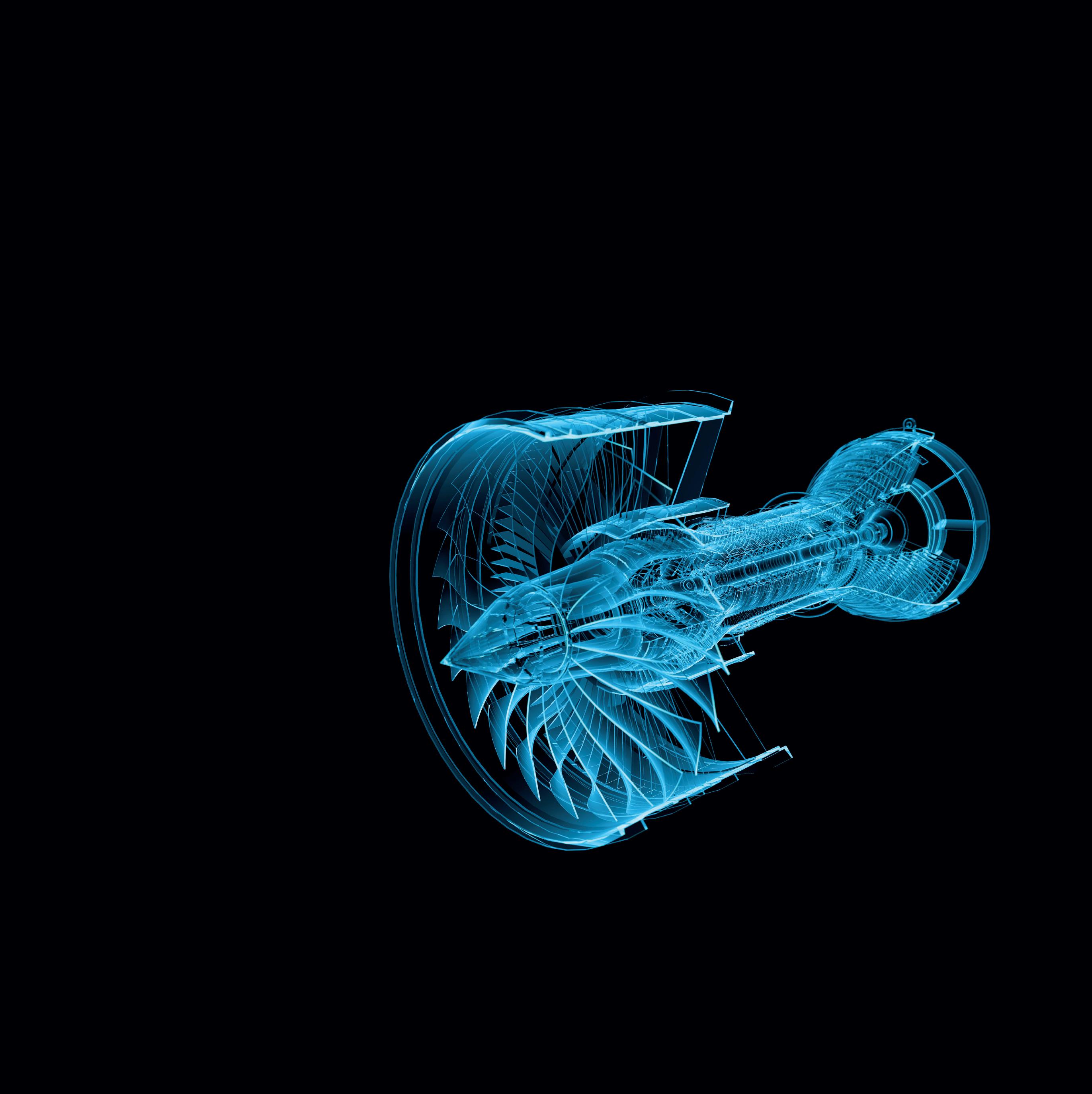
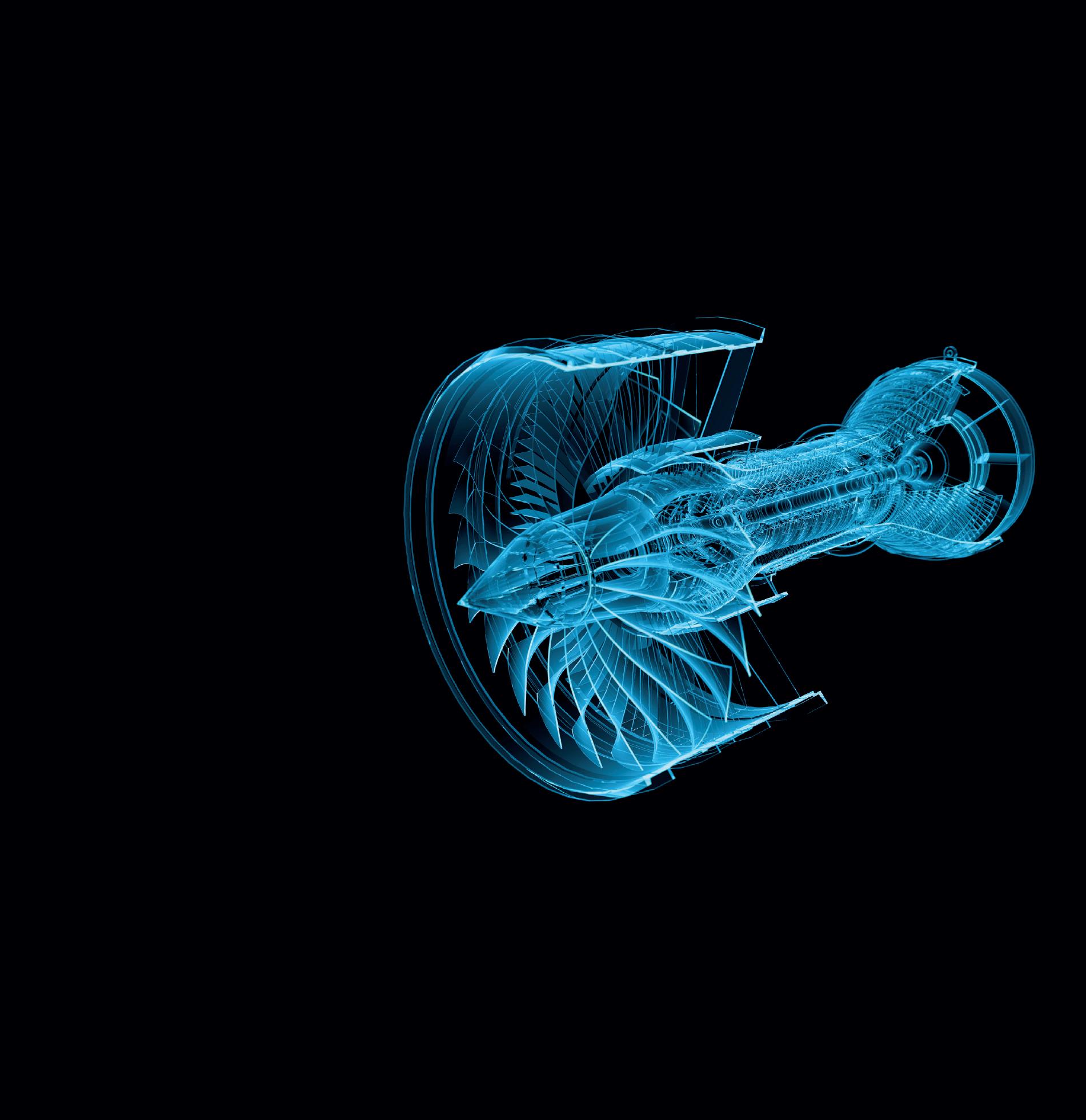
Propelling the future of design

Design Engineering Expo is the brand new event for the sector taking place at NEC on the 7-8 June 2022. With innovation at its heart, the free to attend 2-day event has been created specifically for design engineering professionals and will invite attendees to uncover the latest innovations and technologies driving the sector, celebrate the success stories and reveal those breaking engineering boundaries and provide an unrivalled opportunity to connect with suppliers to help gain the competitive edge and optimise future design strategy.
Running alongside Design Engineering Expo will also be Engineering Expo and Manufacturing Expo, the events together will showcase the complete solutions and supply chain, under the umbrella of Manufacturing & Engineering Week.
Inspiring Keynotes
Packed with invaluable content, the main stage will host an unrivalled line up inspiring leaders and innovators pushing the boundaries of design engineering, they’ll explore the latest success stories, debate current challenges and offer practical how-to sessions to challenge thinking and provide take away solutions to improve process and strategy.
CPD accredited workshops
Delivering tangible value for time away from the desk, Design Engineering Expo will provide a programme of CPD accredited workshop sessions, imparting practical advice and know-how to contribute to personal and professional development.


Whatever your current design challenge, this is an incredible opportunity for design engineers to meet face to face with experts and leave armed with ideas and solutions to apply.
Market leading suppliers


Design Engineering Expo will showcase Britain’s best products and services propelling the future of design engineering. From design services, electronic, embedded design through to testing and measuring, meet the suppliers who can deliver the latest tech and innovations to drive efficiencies and optimise future strategy.
Industry backing
Design Engineering Expo is delighted to announce the Institute of Engineering Designers, Department for Business, Energy and Industrial Strategy, MAKE UK & Advanced Propulsion Centre as partners and the support and guidance of an incredible line up of industry names on the Advisory Board including; Libby Meryick, CEO, Institute of Engineering Designers, Eric Wilkinson, CEO, Cambridge Consultants, Andrew Burrows, Director, PA Consulting, Philippa Oldham, Partnerships Director, Advanced Propulsion Centre and Stephen Phipson, Chief Executive, MAKE UK.
The incredible industry backing indicates the importance and timely relevance of the event for the sector.


“Design doesn’t stop – it’s dynamic, forthright and exciting, and the IED is supporting the launch of Design Engineering Expo to help showcase all of these elements and the outstanding work of the design community now and in the future.”
Libby Meyrick, Chief Executive, Institution of Engineering Designers
Why now?
The UK remains a global force for engineering and manufacturing; driving innovation, leading on the industrial agenda, the green economy, industry 4.0 and being at the forefront of the response to the global pandemic, however in a post-Covid and post-Brexit world, Britain’s standing, and its future, will require engineering and manufacturing to grow and strengthen. Design Engineering Expo, part of Manufacturing and Engineering Week, seeks to celebrate the sector, showcasing innovation, sharing successes and future insight, raise critical discussion and is a destination for professionals to source suppliers and solutions in order to secure the right partners to keep them competitive and grow the UK sector.
“There has never been a more important time for our sector to pull together and to work together, to create a shared agenda, help promote and encourage manufacturing and engineering innovation, and see our sectors grow and Manufacturing and Engineering

Week will do exactly that. I am delighted to be part of the Advisory Board and that MAKE UK a re a partner for this groundbrea ki ng event.” Stephen Phipson CBE, Chief Executive, MAKE UK
Get involved
Design Engineering Expo, together with the collocated events of M&E Week, offers an undeniably value packed event celebrating the sector.
Visitors will save time sourcing new partners, have unrivalled access to industry leaders through inspirational content, stay up to date and return with ideas and solutions in order to stay ahead of the competition. Exhibitors will have the opportunity to meet face to face and do business with engineering professionals across all sectors.
To find out more about Design Engineering Expo and M&E Week visit www.designengineeringexpo.co.uk or follow us on Twitter @DesignEngExpo and LinkedIn.

www.designengineeringexpo.co.uk @DesignEngExpo Part of Cover story
Sustainability quantified:
The key environmental indicators in sustainable material selection


Sustainability is increasingly becoming a central aspect of our world, particularly within the materials industry. Multiple sustainability indicators within environmental, economic and social schemes are specifically sought to ensure sustainable production, use, reuse, and disposal of products and materials. However, the challenge lies in the quantification of these indicators and finding the best methods for measuring and reporting their impacts.
Here, Samir Jaber, Content Writer at Matmatch, explores the most common environmental sustainability indicators in a materials selection process and how they are quantified.

As defined in the Brundtland Report in 1987, “sustainable development is development that meets the needs of the present, without compromising the ability of future generations to meet their own needs.”
Today, sustainability has long passed the association with merely minimising carbon and greenhouse gases. Discussions about sustainability are concerned with various matters of the environment, the economy, and society. These are commonly known as the “three pillars of sustainability”, as they all demand proper management to ensure a sustainable future.
But one question remains: how can we measure sustainability, quantify its impacts, and set meaningful and appropriate goals?
As more ambitious sustainability targets are being set by governments, organisations and companies alike, the challenge of measuring the impacts and meeting demands has become increasingly difficult, yet ever important.
No matter what industry you’re in, sustainable material selection has become a fundamental course of action. Accordingly, here are some of the key and most common environmental sustainability indicators that can go into the material selection process.


Carbon footprint
The carbon footprint of a material refers to the total greenhouse gas (GHG) emissions produced throughout the different stages of the material’s lifecycle, including production, processing, use, and end of life.
Over the whole lifespan, several GHGs can emanate, including carbon dioxide, methane, and nitrous oxide. Such gases have different heat-trapping capacities that contribute to the overall global warming phenomenon. These are measured as global warming potentials (GWPs) in units of carbon dioxide equivalents (CO2e). This allows for a straightforward comparison of carbon footprints of different materials, accounted for by single units.
As climate change has become one of the world’s major challenges, mitigating GHGs and adapting to climate change are now of paramount importance. Initiatives targeted at alleviating GHGs primarily depend on emission quantification, monitoring, reporting, and verification. For that, the International Organisation for Standardisation (ISO) issued the ISO 14060 family
8 dpaonthenet.net
Feature: Sustainable materials
of standards that not only offers a clear and consistent approach to the measures mentioned previously, but also enhances the environmental integrity, credibility and transparency of these measures.

Other indicators under the umbrella of carbon footprint include carbon reduction, carbon offset, and carbon neutrality. While carbon reduction is, as its name implies, the reduction of carbon emissions, carbon offset is that reduction made particularly to counterbalance emissions produced somewhere else. The ideal result from carbon offsetting is known as carbon neutrality, which is net-zero carbon emissions.
Embodied energy
The embodied energy of a material is the sum of the direct and indirect energy inputs involved in resource extraction, transportation, production, processing, and delivery of the material. Embodied energy can also be defined in a way that incorporates the whole lifespan of the material. However, such a measurement is relatively complex to calculate, as it depends on the product the material was used to make. Either way, it is crucial to reduce the embodied energy of a material or product as much as possible to minimise its environmental impact.
Such a sustainability indicator is most commonly found around applications of building and construction, but it is also utilised in other application areas. It is expressed in units of megajoules (MJ) or gigajoules (GJ) per unit weight (kg or tonne) or per unit area (m2). In construction applications, this characterises the measurement of non-renewable energy input per unit of building material or system.
Embodied energy should not be confused with what is known as embodied carbon. Embodied carbon is, basically, the carbon footprint of the material, but it differs based on which part of the material’s lifecycle is considered. It is important to distinguish it from embodied energy as it indicates the carbon emissions involved – not the energy.
Recycled content
Also known as recycled material input, recycled content represents the propor-


tion of material in a product that has been redirected from the solid waste stream. This can happen in two different stages, leading to two different categories of recycled content.
One is pre-consumer recycled content, also known as post-industrial. This is when the material is redirected during manufacturing, before it reaches the consumers. The other one is post-consumer recycled content (PCR), which refers to materials recycled after consumer use.
Recycled content is generally expressed as mass fraction in percent. Common materials that incorporate recycled content include plastics (PET, PP, HDPE, ABS), metals (aluminium, steel), and glass.
The process of recycling materials, whether they fall under post-consumer or post-industrial, plays a significant role in promoting sustainability practices and attaining sustainable materials. It effectively helps to reduce energy consumption and depletion of non-renewable resources.
Given all these metrics, they can all be put together into what we call an environmental sustainability index (ESI), which is a measure of the overall progress towards environmental sustainability. This composite index presents a combination of environmental, socioeconomic and institutional indicators that have quantifiable impacts on environmental sustainability at a national level.
Matmatch has begun to incorporate sustainability indicators in its materials database to help engineers make more sustainable choices. The company put together a guide to sustainable materials selection and is currently collecting data from materials suppliers to make searchable some of the indicators mentioned in this article.
For example, aluminium producer, Nature Alu, is committed to producing fully environmentally friendly and contributing to sustainable development. Its high-purity aluminium (P0101 up to 4N+) has a very low carbon footprint, but it is also designed with the health and safety of employees, and the needs of the client, in mind. Similar suppliers can be found in Matmatch’s database.
By finding the most sustainable materials and identifying their environmental impact, we can contribute to more environmentally friendly and economically viable production. Aspects such as the carbon footprint, embodied energy and recyclability of a material are all very important considerations for any engineering project that is concerned about the wellbeing of society and the planet at large.
If you would like to keep up to date with Matmatch’s efforts and progress, you can sign up for a free account (and make sure to opt-in to the newsletter).
About the author: Samir Jaber is the Technical Content Writer at Matmatch. His background includes mechanical engineering and scientific research in nanotechnology, bioengineering, and materials science, at institutions including the Hong Kong University of Science and Technology and Istanbul Technical University.
https://matmatch.com/ incorporate Feature: Sustainable materials dpaonthenet.net 9
Unison tube bender makes light work of SST’s lifesaving Halo system and other titanium structures
Investing in a Unison Breeze all-electric CNC tube bending machine has assisted SST Technology in becoming the only British-based precision fabricator authorised to produce the life-saving Halo titanium driver protection system, as used in Formula 1. It has also helped the business to complete numerous complex structural projects, involving titanium tubes – including roll-cage structures for military vehicles and aerospace components.
The machine, a Unison Breeze 130mm ‘large diameter’ multi-stack tube bender, was purchased to help SST produce high-performance optimal-flow exhaust systems for Formula 1, IndyCar, and other motorsport sectors. With a pedigree in motorsport components and a powerful new tube bending machine to hand, however, SST’s thoughts quickly turned to driver safety. The exceptionally tight material control, production parameters, and dimensional tolerances provided by the all-electric Unison Breeze tube bender led to the company’s Halo design securing FIA conformity for use in Formula 1, Formula 2 and Formula E motorsport, and being adopted by several race teams. SST’s Halo design requires the precise bending of a titanium tube with 4mm wall thickness.
Notoriously difficult to bend Titanium, however, is notoriously difficult to bend. With low uniform elongation typically requiring a much greater bend radii than other metals, titanium doesn’t readily lend itself to being formed – a characteristic that makes creating tubular structures for aerospace and motorsport applications particularly challenging. For successful

tube forming, the material must be compressed on the inside of the bend and stretched on the outside, while wall thinning and ovality of the tube must be kept to very tight tolerances. Traditionally, ‘hot bending’ – a process involving the use of super-heated tooling – has been used to overcome the challenges of bending titanium.
However, the very process of hot bending presents several issues. For example, the use of super-heated tooling requires considerable care and can present a hazard to operators, complex modifications must be made to bending machinery, and tooling heat-up times are lengthy. By contrast, Unison’s infinitely controllable and robust all-electric machines enable the safe, precise cold bending of titanium. With advice and application support from the technical
team at Unison Ltd, SST was therefore able to develop a cold-bending process for its Halo design, that allowed for the low elongation of the metal and delivered precise results.

“To successfully cold-bend titanium, factors such as material quality, tooling configuration, machine design, and flexibility of control need to be considered,” comments Unison Key Account Manager, Steve Haddrell. “This is because any variation in material quality, any lack of rigidity in the mechanics of the bending machine, and any failure to achieve repeatability time after time, will invariably lead to failure. With exceptional power, optimal rigidity, precise mechanical motion and all-electric control, for accurate, effortless repeatability, we knew the 130mm Breeze was the ideal machine for precision-bending SST’s

Feature: CNC tube bender 10 dpaonthenet.net
Halo design. With material quality assured, it really came down to working with SST to establish the correct tooling configuration and programming of the Unison Unibend machine operating system.”
Delivering significant benefits
“Investing in the 130mm Unison Breeze machine has clearly paid dividends,” says SST Technology’s Group Business Development Director, Daniel Chilcott. “Tool changes are rapid, programming is incredibly user friendly, while the automatic setup ensures uncompromising levels of accuracy and repeatability. Sufficiently impressed with the capabilities of our 130mm machine, we have also purchased a smaller 65mm Breeze model for the production of more intricate pipework and parts for aerospace and gas turbine applications. Combining this capability with our AS9100REVD accreditation means we are perfectly set up to support leading aerospace propulsion, fluid and air system OEMs.”
Intelligent tube manipulation

The Unison Breeze 130mm tube bender purchased by SST is well suited to manipulating exotic alloys, such as titanium
and Inconel, as well as Super-Duplex stainless steels, and provides high-quality thin-wall bending. Multi-stack tooling allows the most complex of parts to be formed in one uninterrupted manufacturing cycle, while Unison’s bar code scanning system ensures that only the correct tooling is installed. The standard-fit rise and fall pressure die can result in significant savings in tooling costs and allows tools of very different radii to be used on a part within a cycle. The tube bender can be programmed manually or from CAD data, using industry-standard IGES or STEP files.


“At Unison, we are often invited to advise customers on particularly challenging tube bending projects,” concludes Steve Haddrell. “That’s partly because of the immense capabilities offered by our tube bending machines. Assisting SST [in] establishing the optimal tooling configuration of their Unison Breeze machine, for the production of the life-saving Halo device, however, is one of the most rewarding projects we have been involved in.”

www.unisonltd.com Feature: CNC tube bender www.binder-connector.co.uk M8 12 contacts Cable &
panel mount connectors
IP67
PUR-/PVC cable
Is greener innovation inaerospace possible?


Current legislation, aimed at curbing emissions, is fuelling materials innovation for aerospace components and, as global standards get more stringent, the pace of change is quickening. Now is the time for design engineers to look beyond traditional choices, to prompt radical transition, urges Richard Thompson, Commercial Director of Alvant.
Composite materials have revolutionised the aviation industry. But while what has been achieved with the 787 is an incredible feat of engineering, using composites does present some engineering and maintenance challenges, as well as placing the issue of sustainability under the spotlight.

Composites are also not delivering all the supposed guarantees: tales of patching composite structures and engineers overcompensating on calculations (due to a


The future of design engineering.


Feature: Aerospace sustainability
• Inspiring keynotes • CPD accredited workshops • Market leading showcase of Britain’s best suppliers NEC BIRMINGHAM - 7-8 JUNE 2022
A lighter solution
So, what about potential alternatives?
There is no obvious quick fix, but now is the time for design engineers to look be yond traditional technologies and embrace long-term change. This means lighter weight materials that enhance capability and offer a good value alternative to mate rials that include carbon and polymer com posites, steel, titanium, and aluminium.
Aluminium matrix composites (AMCs) are relatively new in aerospace, but we are starting to see demand increase as the industry responds to the need to lower costs, reduce weight and cut carbon emis sions through less fuel burn.
An AMC is aluminium combined with a high-performance secondary material, increasing stiffness by up to four times, compared to some grades of aluminium. It is suitable for applications where conven tional metals are expected to approach or exceed their performance limits, whilst be ing more tolerant to physical and thermal
Having such durability, higher strength and stiffness paves the way for aerodynamic components that are thinner, wider, and, overall, more weight efficient.
Wider reaching benefits
Propellers and seats are just two of the many parts of an aircraft that can signifi cantly benefit from AMCs. Alvant is already testing and developing landing gear com ponents, and is investigating its use in wing features and structures. The future possi bilities are extremely diverse.
Alvant developed and refined AMCs during the years when high-tech industries were going through the honeymoon period with carbon composites. Nowadays, certain disadvantages with carbon composites and polymer composites are better under stood.
Add increased reliability and low life-cy cle costs to the list of benefits brought by AMCs, and it will be no surprise when we see more and more aircraft manufacturers
components’ weight. Safran formed a col laboration to operate under a grant from ATI (funded by Innovate UK) – to develop and showcase the most innovative new technologies that would underpin the en gineering and manufacture of landing gear in 2020 and beyond.

Alvant’s contribution to the project is the design, manufacture and testing of an AMC brake rod, targeting a 30 percent weight reduction over an equivalent tita nium component, whilst maintaining the same strength as steel. This will all be done using its own ‘AlXal’ product (pronounced Al-Zal) – a continuous fibre-based AMC, which is the result of a process created and patented by Alvant, known as Ad vanced Liquid Pressure Forming (ALPF). This technology brings together alumini um (the matrix) and the high-strength rein forcement materials, to create AlXal.
The project, now in its final stages, will un dergo its first prototype component cast ing trials, with component testing sched
About the author: Richard Thompson, Commercial Director (BEng MBA CEng FIMechE).
Richard is a technology commercialisation professional, specialising in strategic market development, innovation, and new venture growth. Richard joined Alvant in October 2017 from Williams Advanced Engineering, the technology and engineering consultancy division of the Williams Formula 1 Group. He has worked for a range of high-performance engineering businesses and new venture companies, developing and commercialising intellectual property. Richard was appointed

Feature: Aerospace sustainability
www.designengineeringexpo.co.uk @DesignEngExpo Part of
Well, colour me pink!
That’s how Masterbatch works
If you’re looking to achieve a splash of colour, texture, or even antibacterial properties into your plastic components, chances are your moulder is using masterbatch in the mix. With the global masterbatch market set to increase in value to USD 15 billion by 2026, Jo Davis, Managing Director at Broanmain Plastics, explains why masterbatch is so popular and how, as a moulder, it goes about achieving the perfect blend to ensure consistency.


Masterbatch is commonly divided into five segments: black, white, colour, additive, and fillers. Each formulation offers different functions that, when distributed evenly through the polymer mix, give it its unique plastic fingerprint.
Colour masterbatch is a highly concentrated pigment. Supplied in pellet form, rather than powder or liquid, it is blended into plastics to create a range of enduse applications, for example, food and beverage packaging, appliances, automotive, and pharmaceutical packaging.

Additive masterbatch offers improved performance of plastic products. For instance, illumination, UV resistance, anti-oxidants, antimicrobials, or anti-static. Filler masterbatch is used to create better properties, such as stiffness or a


lighter weight polymer. Chalk, for example, is used to bulk out the plastic. Specific fillers can also be added to make a component fire retardant.
Black and white masterbatches are typically used in building and construction, automotive, consumer goods, and domestic appliances.
Achieving a special effect, such as chrome, wood grain, stone, marbling and even sparkle, is also possible. These types of compounds are often used to boost consumer appeal and mimic heavier materials.
Ready mixed or create on demand?
Compounded mixes might be purchased in bulk when creating larger
quantities of components. But, for many end customers, masterbatch is often the most cost-effective way for moulders to create the perfect recipe.
Blended in-house, moulders use volumetric dosing units to mix the material automatically, ready for processing. Using granular masterbatch can be a lot less messy than powders or liquid, with fewer health and safety risks from dust or spillages.
The ability to maintain a low stock holding and call up a specific blend, when required, from an external supplier can be more economical, helping to keep production costs down on short runs.
Universal masterbatches offer convenience, are more readily available from suppliers, and work with most polymers. The downside is not all universal masterbatches are compatible with all base materials. Conversely, polymer-specific masterbatches are formulated using the same base polymer with which it will be blended. These tend to be bespoke and customised to suit a customer’s requirement for pigment colour, as well as special properties, like heat stability.

Feature: Masterbatch 14 dpaonthenet.net
Out of all the product types, colour masterbatch is experiencing heavy global demand. (iStock.com/LeeYiuTung)
Jet blacks and bright whites
For several components, such as electronics, producing the deepest blacks and the purest whites can be more challenging than some think. It requires a high pigmentation concentration – especially to make contemporary products, such as mobile phones, stand out. Achieving uniform colour is critical. Although there is usually a standard range of around 40+, there can be over 1000 different masterbatch formulations.
Typically, a white masterbatch is used to add opaqueness or whiteness into plastic products. Different grades of titanium dioxide (TiO2) are applied to reflect or scatter light. As well as outdoor applications, some whites are suitable for food contact plastics. One of the key advantages of the white masterbatch is that it has a high rate of dispersion, so can easily incorporate other colourants.
Black masterbatch is good for electro-static conductibility, durability, and exposure to extreme weather. That’s why black is used in a lot of functional outdoor plastic applications, such as construction pipes, as it is stronger and lighter than coloured equivalents.

Performance-enhancing additives are often added to both black and white masterbatches.
Colour matching

Picking the perfect colour is one thing. Ensuring consistency, batch to batch, is quite a science. Everyone sees colour differently. While Newton divided the spectrum into seven base colours – red, orange, yellow, green, blue, indigo, and violet – according to psychophysicists,

we see tens of millions of different hues and shades. Given this, the human eye cannot be relied upon to match samples accurately.
Once a specific masterbatch has been created, specific formulation details, including colour pigments, raw material ratios, notes and directions are held on a recipe card. A moulder can call up these instructions at any time to ensure production consistency.
Should a recipe card be unavailable, physical samples can also be matched using a light box or spectrophotometer.

Homogenisation of a blend, including the dispersion of the masterbatch during dosing, plays a big role in minimising colour and product performance variations. Most recipes detail the percentage by the weight of masterbatch to be applied. Yet, discrepancies can occur. Changing the host polymer or switching suppliers is typically when this might happen, so moulders tend to stick with the same supplier.
As with all plastic processing, stability is essential. Thermal resistance and durability need to be factored in, which is why most processors avoid using a high percentage of recycled plastic mixes for the base polymer. The more plastic is reprocessed, the greater the molecular structure changes. This loss of chemical properties affects the composition and, therefore, is likely to affect the compatibility of all the ingredients within a blend.
Aesthetics aside, understanding the environment in which the end component will be used is critical. For example, components exposed to direct sunlight will need to use a specific masterbatch to prevent discolouration. The chemistry of some colour pigments may be incompatible with the chemistry of some base polymers. Additionally, other agents, such as fillers, could impact the fusion.
One thing is certain, masterbatch has become integral to modern-day plastic processing. Out of all the product types, colour masterbatch is experiencing heavy global demand. This robust growth can be attributed to brand differentiation trends in packaging, FMCG, furniture, construction, agriculture, and aerospace. Likewise, black and white mastermatches are being extensively utilised by automotive manufacturers for lightweighting and to improve fuel efficiency.
Just like a paint swatch, new innovations emerge on the market all the time. To trial a different pigment or plastic effect, contact Broanmain Plastics.

About the author:

Jo Davis is Managing Director of Dorkingbased Broanmain Plastics. Jo has led the operations at the family precision and technical plastics injection moulding business since 2018. For the past 12 months, Jo and the team have concentrated on streamlining operations, new machinery acquisition and crossskilling staff across two sites, and building a culture of innovation and continuous improvement, as well as being a committed member of the British Plastics Federation and the GTMA.

www.broanmainplastics.co.uk Feature: Masterbatch
Stocked non-metallic industrial enclosures Environmental sealing up to IP68 Learn more: hammfg.com/uk-ind uksales@hammfg.com • 01256 812812 IP66 PJU Polyester IP68 1554 Polycarbonate Masterbatch colour is a highly concentrated pigment which moulders blend with base polymer resins and additives to achieve a special formulation (iStock.com/Irina Vodneva)
Miniature
Custom engineered for critical performance

MOTORS THAT SAVE, IMPROVE AND ENHANCE LIVES


Motors
When you need to put the most power and precision in the smallest spaces you can depend on the engineering experience, application support and manufacturing excellence of Portescap.
www.portescap.com Tel: +41 32 925 62 40 Email: sales.europe@portescap.com Estore Now Available!
Why you should upgrade to IE5 ultra-premium motor efficiency

Upgrading to a package that combines a synchronous reluctance motor (SynRM) with an IE5 ultra-premium efficiency rating and a variable speed drive (VSD) not only saves on energy and maintenance costs, but improves productivity and answers sustainability concerns – Tero Helpio of ABB Motion explains.
While electric motors keep the world turning safely and reliably, there is a price to pay in terms of energy consumption and associated CO2 emissions. Around 70 percent of all electricity used by industry is consumed by electric motor systems.
The EU Ecodesign Regulation addresses this for low-voltage motors by establishing and enforcing International Efficiency (IE) classes defined by the International Electrotechnical Commission (IEC). From July 2021, it sets IE3 as the minimum standard, including motors used with VSDs. There is also the IE5 ultra-premium rating that goes well beyond the EU Ecodesign regulation, but some manufacturers are already supplying motors compliant with it. Industrial operators can upgrade now and enjoy practical and economic advantages – as well as demonstrating their environmental responsibility.
IE5 SynRM motors can reduce energy losses by 40 percent and significantly lower energy consumption, compared to the commonly used IE3 induction motors. Exact energy savings vary with applications and conditions, but indus-

trial case studies with SynRM motor and VSD packages have shown typical reductions in energy bills from 14 to 25 percent, compared to the replaced motors.
If 80 percent of today’s installed industrial motors were replaced by IE5 units, the estimated annual energy saving would equate to the annual power consumption of Poland. There are also other substantial benefits to be gained from IE5 SynRM motors, including lower maintenance needs, higher reliability, longer equipment life, and better performance.
What is different about a SynRM motor?
From the outside, a SynRM motor looks very much like an induction motor. Inside, the innovative rotor structure is very different, as it has no windings at all. It contains stacked steel plates with intervening spaces that form a light but
robust structure. Furthermore, the rotor does not contain magnets or rare earth metals, unlike other synchronous motors, such as permanent magnet (PM) motors. This contributes to sustainability, as the production of rare earth metals has a serious environmental impact and limited potential for recycling.
The SynRM motor’s stator establishes a magnetic flux which the VSD controls and rotates. The rotor, remaining aligned with the rotating flux, is pulled around –and thus, torque is created. Meanwhile, the VSD monitors the rotor’s position and keeps it synchronised.
In conventional induction motors, heavy currents flow due to the squirrel cage rotor design and the short circuit formed by its end rings. These currents account for around 40 percent of the motor’s energy losses, resulting in the generation of additional heat.

dpaonthenet.net 17
Feature: Motor efficiency
Synchronous reluctance technology combines the performance of a permanent magnet motor with the simplicity and service-friendliness of an induction motor
By contrast, SynRM rotors have no squirrel cages or windings to generate currents and heat, so energy losses are virtually nil. IE5 SynRM technology provides performance comparable to that of permanent magnet motors, but without the environmental costs of rare earth magnets. At the same time, it offers the simple maintenance of an induction motor.
Higher efficiency and more
In addition to their verified IE5 efficiency, cutting energy losses by 20 percent compared to IE4 super-premium motors and by 40 percent compared to IE3, SynRM motors are superior in other ways. They run at cooler temperatures than induction motors, which extends the life of stator windings, bearing lubricants, and the bearings themselves – and reduces the need for cooling of workspaces.
Lower running temperatures and their relatively simple construction make IE5 SynRM motors easier to service and extend their servicing intervals. Risks of failure are smaller and, for extra confidence, the motor and drive’s monitoring connections can be used to detect problems.
IE5 SynRM motors are also significantly quieter than traditional induction motors, so working environments are more comfortable.
IE5 SynRM motor and VSD –the perfect package for any application
A SynRM motor is always installed with a VSD to form an optimised package. In the most common motor applications, such as pumps, fans and compressors, a VSD typically saves about 25 percent on energy consumption. This is because the VSD adjusts the motor’s speed and torque to match the load, rather than running at full speed all the time.
Currently, a wide range of VSDs is programmed to work with IE5 SynRM motors. Extensive testing has been carried out with ABB’s VSDs, which feature the latest purpose-designed software for extremely precise and dynamic control. The versatility and accuracy of both the motor and VSD ensure excellent speed stability, which is often essential to maintain product quality and minimise rejections. Accurate control at low speeds, right down to zero, allows constant maintenance of optimal torque, without tripping. ABB’s direct torque control (DTC) precisely governs speed and torque, without speed sensors, encoders, or other feedback devices.
This flexibility and precision enable IE5 SynRM motors to replace standard induction motors in any application. They are highly accurate and efficient across the whole speed range, even with partial loads, and can deliver full torque from zero speed. In addition to providing quadratic torque with high efficiency in machines like pumps, fans and compressors, they can supply constant torque with precise control in demanding applications, such as extruders, mixers, winches, and conveyors.
SynRM technology proven in the field

The performance and efficiency advantages of ABB SynRM and VSD packages have been proven in a variety of case studies. Most recently, Campbell’s – famous for products such as soups – implemented a package in a refrigeration compressor at its Shepparton plant in Australia. Along with a 14 percent reduction in energy costs, the company noted reductions in running temperature, vibration, and noise.
Evides Waterbedrijf, a large water business in the Netherlands, has used similar pump and drive packages for vital pumping machinery. The energy saving was estimated at 20 percent, while cooler running was expected to extend motor and bearing life. This was a key factor in the company’s decision, as it required a 20-30-year life expectancy from the equipment.
In the plastics sector, Radius Systems replaced a troublesome DC motor on an extrusion line at its Derbyshire plant with a SynRM motor and VSD package. It met all challenges, including the need for a high starting torque, followed by constant torque, and delivered an estimated energy saving of eight to 15 percent. It saves around £2,000 annually on maintenance, and its quiet operation has also been welcomed.

Plastic container manufacturer, PrimePac, had problems with a worn-out hydraulic motor on a blow moulding machine at its plant near Belfast. As well as consuming energy excessively, it was producing poor bottle quality, due to inaccurate speed holding. A SynRM package not only solved those problems, but with an energy saving peaking at 60 percent, it enabled PrimePac to install a new extruder – without having to spend £250,000 on upgrading the site’s power supply.
An easy swap and early payback
Replacing an existing induction motor with an IE5 SynRM motor is simple. They have the same dimensions and output power, so there is no need for mechanical modifications to existing setups. The additional cost of specifying an IE5 SynRM and drive package, rather than an IE3 motor and VSD, can have a payback time as short as one year. It’s time for industry to consider upgrading motors to the ultra-premium efficiency made possible by IE5 motors with VSD control.
For further information, visit https:// new.abb.com/motors-generators/ iec-low-voltage-motors/process-performance-motors/synchronous-reluctance-motors.
Evides Waterbedrijf has used installed SynRM pump and drive packages with energy savings estimated at 20 percent
18 dpaonthenet.net Feature: Motor efficiency
About the author: Tero Helpio is Global Product Manager, IEC LV motors, at ABB Motion.
Size Isn’t
A powerful, compact and flexible machine controller, our Flex-6 Nano delivers up to 64 axes of motion, plugs directly onto our EtherCAT Flexslice IO System and features our Motion-iX core that includes IEC61131, PLCopen and robotics motion


All at just 147mm small, the Flex-6 Nano packs in a big specification into a small footprint.


Trio
find
Flex-6 Nano
Powerful control in a small package


Oriental Motor’s AZ Series in Robotic Applications


The food packaging industry is a key market for Oriental Motor. Standard production lines often consist of several different machines purely to package food. These may all be from different, specialist manufacturers. But Oriental Motor has the technological ability and scope to supply motors for the whole production line.

The majority of packaging in supermarkets is made with a thermoforming machine using a hot press to mould the material into the desired tray shape. Brushless DC (BLDC)


have the solution.
motors with hollow shaft right angle gearheads deliver high torque for driving the presses. Standard geared types are ideal for tension control of the packaging material, winding up waste material, and driving the completed tray conveyor. Variable speed BLDC motors are also used for positioning trays for sealing.


For more information about Oriental Motor’s AZ Series, call the Oriental Motor team on +44 (0)1256 347090.

Everything...
Contact
to
out more.
not as big as it looks.indd 6 06/05/2021 13:34:12 dpaonthenet.net 19
BLH Series Oriental Motor (UK) LTD www.oriental-motor.co.uk – info@oriental-motor.co.uk – 01256 347 090 EZS Series AZ Series CVK Series BLE2 Series KIIS Series DGII Series KIIS Series Angle Gearboxes STEPPERMOTORS BLDC MOTORS AC MOTORS ACTUATORS We
Position. Transport . Rotate Advertorial
Choosing the right drive strategy for stepper motor applications

Stepper motors are popular choices for many motorised systems – in particular, because they are easy to drive. But having knowledge of the various stepper motor technologies and the ways they can be controlled can be a significant advantage. With an understanding of bipolar and unipolar driving methods, designers will be in a better position to implement a truly optimised solution.
Clémence Muron, Application Engineer at Portescap, discusses the differences between bipolar drives and unipolar drives for stepper motors, and examines their advantages and limitations in specific applications.

For motor-driven applications that require precise and predictable positioning in a compact, cost-effective package, stepper motors have been a popular
choice since their introduction in the 1960s. In recent years, advances both in the motors themselves and in the drive electronics have given steppers decisive performance advantages in demanding applications – from machine tools to medical equipment.

The simplicity of the drive technology for modern steppers is one of the keys to their enduring popularity, but even so, there are design decisions that need to be made in the control concept which can have a huge bearing on the success of the application. In particular, should the designer opt for unipolar control or bipolar control of the motors?
It is true that many stepper motor applications today are implemented with a bipolar drive. However, unipolar motors are still available on the market and there is a case to be made for unipolar in certain circumstances. It’s by appreciating the differences – some advantageous and some disadvantageous – of these technologies, that the designer will be best placed to make the most appropriate technology decision for a given application.
The stepper motor is a type of brushless DC motor with a high number of poles. This technology is generally driven in an open loop without any feedback sensor,

20 dpaonthenet.net Feature: Stepper motors
Diagram of a four-step, permanent magnet stepper motor. The rotor is made with a one pole pair magnet, and the stator is composed of two phases, Phase A and Phase B
A
unipolar motor is composed of two coil windings per phase. For each coil, the current can only flow in a single direction. Voltage drive is simple, requiring one transistor per coil
Stepper motors
meaning the current is typically applied on the phases, without knowing the rotor position. The rotor moves to be aligned with the stator magnetic flux, then the current can be supplied to the next phase.
As previously mentioned, there are two ways to supply current in the coil: the bipolar way and the unipolar way. A unipolar motor requires a minimum of two coils per phase, and the switching of the transistors in drive electronics sees current flowing in only one direction for each coil. The drive electronics are easy to realise because there is only one transistor per coil. When the transistor is closed, the coil is powered. To turn the motor, the transistors are closed and opened in sequence.
In contrast, a bipolar motor requires a minimum of one coil per phase and the current can flow in both directions through the coils. In the drive electronics, twice the number of transistors is required for a motor with the same number of phases.

With regard to wiring, a unipolar motor might be supplied with six or eight wires, while a bipolar motor is typically supplied with four or eight. For the eightwire versions, depending on how these wires are connected, the motor can be configured as either unipolar or bipolar. For the bipolar, the coils can be mounted in series or in parallel, which has implications for the electrical characteristics of the coils, impacting on voltage and resistance. The eight-wire version gives greater flexibility to the designer in meeting the particular performance needs of the application.
Advantages and limitations


There are a number of different control strategies that we can consider, but let’s look first at voltage drive and current drive. In the case of voltage drive, controlling unipolar motors is very easy, requiring just four transistors. A bipolar controller for voltage drive, on the other hand, requires eight transistors, configured in two H-bridges. For voltage drive, then, the unipolar control strategy provides a far simpler and more affordable solution.
But there are also performance considerations to take into account. In the voltage drive, the bipolar motor offers more torque, while a unipolar motor presents lower torque at low speed, primarily because of joule losses. However, in a specific case at high speed, the unipolar can sometimes offer higher torque than bipolar, as the current can flow more quickly in the coil.

Where torque is important, the bipolar motor can produce generally 40 percent more torque than a unipolar drive – or, to look at it another way, for the same dissipated joule power, the bipolar drive gives better power than a unipolar drive.
But what about current drive? With the cost improvement of electronics, pulse width modulation (PWM) has become the preferred choice for controlling stepper motors, varying the duty cycle at a fixed frequency to adjust the voltage or current within the desired target value. For a current drive, the PWM controls the current in each phase.
With a bipolar motor, modern drive electronics make it relatively easy to implement a PWM current drive, bringing with it the possibility to drive the motor in micro-steps. Driving a unipolar motor in current mode requires much more complex electronics, while yielding lower motor performance.
In conclusion, we have seen that, with the advantages of PWM control and the cost improvement of electronics, there is a growing trend towards the use of bipolar stepper motors in current drive. But for a voltage drive, if simplicity and/or cost are key considerations – or where increased torque at higher speeds is required – the unipolar drive can still represent a useful option.
As ever, it is worth engaging with a knowledgeable supplier, such as Portescap, at the earliest stages of a project, so that the designer can be assured of the most appropriate solution for a given application.
https://www.portescap.com/

Feature:
About the author: Clémence Muron is an Application Engineer and Channel Partner Support at Portescap, with extensive experience in project management, design and development, and a proven track record of successfully providing technical assistance for customers in motion critical applications. She holds a combined Bachelor’s and Master’s degree in Mechanical Engineering from ECAM Lyon, France.
Torque versus speed, in voltage drive mode, for unipolar and bipolar motors
dpaonthenet.net 21
Bipolar motors need only one coil winding per phase, and current can flow in either direction. For control, eight transistors with two H-bridges are required
EU 2019/1781 comes into force: Energy efficiency requirements don’t stop here


So, you’ve probably heard a lot about the new ecodesign requirements for motors and variable speed drives (VSDs) that come into force on 1 July 2021? This is only the latest stage in the EU’s decade-long roadmap of efficiency improvements, including motors and now VSDs – but what’s next? Here, Marek Lukaszczyk, European and Middle East Marketing Manager at WEG, explains the short-term and long-term considerations for industry.

In 2019, the EU member countries passed more demanding requirements for motors, outlined in the new regulation, EU 2019/1781. This will repeal and replace the earlier regulation 640/2009, which allowed IE2 motors to be used with VSDs.
Initial calculations based on the Working Plan – the umbrella initiative associated with the earlier regulation – estimated the potential to deliver a total in excess of 260TWh of annual final energy savings in 2030, across the continent. This is equivalent to reducing greenhouse gas emissions by approximately 100 million tonnes per year in 2030. Electric motors were one of the priority product groups listed in the Working Plan, with the earlier legislation estimating 10TWh of annual final energy savings from this product group in 2030.
By introducing the new regulation EU 2019/1781, additional net electricity savings of 10TWh per year are expected to be achieved. This should reduce net greenhouse gas emissions by 3Mt CO2 equivalent, annually, by 2030.
What are the 2021 changes?
From 1 July, lower efficiency products will no longer be accepted, as a wider range of motors is brought into scope and held to higher standards. This applies to products placed onto the market or put into service in Europe after these dates. However, exceptions exist when repairing products containing motors that were placed on the market before the new regulation came into force. This will avoid scrapping equipment early if motors can be repaired and is designed to avoid problems if it is impossible to replace a non-compliant motor with a compliant one, without disproportionate costs to the end user.
22 dpaonthenet.net Feature: Ecodesign requirements
Previously, the scope of the regulations only covered three-phase motors, ranging from 0.75kW to 375kW – leaving motors outside this power range excluded. From July, this will no longer be the case. The impending regulation requires all-new 2-, 4-, 6- and 8-pole motors, in the power range of 0.751000kW, to meet the IE3 efficiency class. Also included are Ex ec, Ex d, Ex de, Ext motors, brake motors with an external brake, and motors with IC418 cooling. Sizes from 0.12-0.75kW will also need to meet IE2 class for the first time.
About the author: Marek Lukaszczyk is the European Marketing Manager at WEG. With over 20 years’ experience at the company, he leads the marketing campaign across Europe and the Middle East region.
The previous legislation allowed for an IE2 motor to be used, provided it was controlled by a VSD, but this will no longer be valid. Drives are also included for the first time, with AC drives needing to meet their own classification of IE2.
As with the 2016 updates to the legislation, that saw the market share for IE3 premium class motors rise from zero percent to 29 percent, we are likely to see a continued shift towards energy-efficient products in response to these latest regulations.
The long-term vision
Instead of viewing the new ecodesign requirements as restrictive, plant managers should see this as an opportunity. After all, the investment in energy-efficiency drives and motors, even if it’s not through choice, usually provides a very short return on investment.
They say that the key to success is always looking one step ahead. Thanks to significant investments in research and development, WEG, for many years, has had available a range of hazardous area motors, meeting efficiency classes IE2, IE3 and IE4 to IEC standards. However, the IE2 efficiency class will be mandatory for Ex eb safety motors, from 0.12 to 1000kW, and single-phase motors for the same rated power output range.
The WEG Super Premium range of IE4 motors will prove useful, as, from 2023, 3-phase motors with 2-, 4- or 6-poles, that are equal or exceeding 75kW and equal to or below 200kW, will need to meet IE4 efficiency levels. This does, however, exclude brake motors and Ex-motors.
WEG encourages motor buyers to share their forward-thinking philosophy and consider not only the impact of the changes that come into force this year, but also look ahead to the regulation of 2023 and beyond. For example, currently, no classification exists for the energy efficiency of electric motors with a rated voltage above 1000V. Once such a classification is developed, the possibility of setting minimum requirements for medium-voltage motors could be reassessed.
While clear legislative steps have been taken to reduce the environmental impact of electric motors and VSDs, this is but one step in the continued effort by the Government, motor manufacturers, and end users to improve long-term efficiency in the industry.
For further information about WEG’s energy-efficient motor and VSD lines, visit www.weg.net.

SMART AND DIGITAL AUTOMATION
SPECIALISING IN SOLUTIONS


Packaging Machinery Theatre Systems Metal Processing

Automation with Drive www.keb.co.uk KEB (UK) Ltd. 5 Morris Close Park Farm Industrial Estate Wellingborough NN8 6XF Tel: 01933 402220 E-Mail: info@keb.co.uk
Textile Machinery Process Engineering Lift & Escalators Intralogistics Plastics Machinery e-mobility AutomotiveWood Working Wind Power
Feature: Ecodesign requirements
dpaonthenet.net 23
Why and how to use a component-based distributed power architecture for robotics


The use of battery-powered robots is growing across applications such as factory automation, agriculture, campus and consumer delivery, and warehouse inventory management. For a maximum operating time between charges, designers of these battery systems have always needed to be concerned about power conversion efficiency, as well as size and weight.


However, these concerns have become more critical as load capacities continue to increase and sensing and safety features – such as vision, ranging, proximity, location, among others – add design complexity and physical weight.


The additional electronics processing required also consumes more power.


24 dpaonthenet.net
Feature: Power architecture
To maximise battery life in the face of these additional challenges, designers can turn to a component-based distributed power delivery architecture. In such an approach, each individual DCDC power conversion component can be placed at the point of load (PoL) and optimised for high efficiency, small size, and overall performance. This approach can result in a lighter overall power system, enabling further performance gains for battery-powered robotic systems. Flexibility is also enhanced, since power conversion components can be paralleled to scale easily, as robotic power demands increase. They also allow for the same power architecture to be deployed across a platform of robotic systems of various sizes.
Power requirements for robots
The power requirements for specific types of robots are determined by the application:
• Agricultural harvesting robots: Plant, maintain, and harvest produce using automated vehicle guidance, along with visual recognition and multiple environmental and soil analysis sensors. These large robotic vehicles are typically powered from a high-voltage DC source of 400 volts (V) or more.
• Delivery robots: Last-mile consumer or campus delivery of various items. While payloads vary in size and weight, these robots are typically powered by 48-100V batteries and have longer run-time requirements than the warehouse inventory moving class of robots.
• Warehouse inventory moving robots: Provide inventory management and order fulfilment tasks within large warehouse environments. This robot class is typically powered from a 24-72V battery source with opportunity charging performed on an as-needed basis.
Component-based distributed power architectures for robotics
This section reviews four examples of component-based distributed power architectures for robots ranging from a 15.9 kilowatt (kW) system, for agricul-


tural harvesting robots with a 760V battery pack, down to a 1.2kW system for warehouse inventory movement robots – using a 48V battery pack. A common feature in three of these applications is a relatively high voltage main bus that distributes power throughout the robot, followed by one or more voltage stepdown sections that deliver the needed power to the subsystems. The fourth application shows the simplification that can result in smaller robots that use 48V battery systems.
The power delivery network (PDN) for agricultural harvesting robots comprises a 760V main power bus. This is supported by a series of fixed ratio (unregulated) isolated DC-DC converters, with an output voltage of 1/16 of the input voltage. These converters are used in parallel, enabling the system to be resized, according to the needs of the specific design.
Further into the network, a series of fixed ratio, regulated buck-boost and buck converters power downstream, lower voltage rails, as needed. In this design, the servo is driven directly from the 48V intermediate power bus, with no additional DC-DC conversion.

The PDN for campus and consumer delivery robots shows the simplification that can result in medium power systems, by employing a lower main power bus voltage (in this case, 100V), and adding regulation to the isolated DC-DC converters (DCMs) on the main power distribution bus to produce the 48V intermediate bus voltage.
This approach enables the use of non-isolated buck-boost and buck DC-DC converters to power the various subsystems. In addition, the use of a lower voltage for the main power bus enables the motor drive to connect directly to the main bus, while the servo can connect directly to the 48V intermediate bus. Smaller campus and consumer delivery robots may incorporate a 24V intermediate bus voltage and either 24V or 48V servos, but the overall architecture is similar.
The PDN for warehouse robots using

a 67V battery pack highlights the use of buck-boost non-isolated DC-DC converters (PRMs) on the main power bus. These converters provide efficiencies of 96 to 98 percent and can be paralleled for higher power needs. This architecture also features a fixed ratio, non-isolated DC-DC converter (NBM) to power the GPU, and non-isolated regulated buck converters, powering the logic sections.
For smaller robot designs using a 48V battery, there is no need to generate an intermediate bus voltage, simplifying the design. The loads are powered directly from the battery voltage by direct conversion, using various non-isolated DC-DC converters. The elimination of the intermediate bus in the power train increases system efficiency and reduces the weight and cost of the power system.

Feature: Power architecture dpaonthenet.net 25
Figure 1: The DCM3623TA5N53B4T70 isolated and regulated DC-DC converter can produce the 48-volt intermediate bus voltage from 100-volt battery power. (Image source: Vicor)
Figure 2: The DCM3623EA5N53B4T70 evaluation board enables designers to explore the capabilities of the DCM3623TA5N53B4T70 DC-DC converter. (Image source: Vicor)
About the author: Rolf Horn, Applications Engineer at Digi-Key Electronics, has been in the European Technical Support group since 2014, with primary responsibility for answering any development- and engineering-related questions from final customers in EMEA, as well as writing and proofreading German articles and blogs on DK’s TechForum and maker.io platforms. Prior to Digi-Key, he worked at several manufacturers in the semiconductor area, with a focus on embedded FPGA, microcontroller and processor systems for industrial and automotive applications. Rolf holds a degree in electrical and electronics engineering from the university of applied sciences in Munich, Bavaria and started his professional career at a local electronics products distributor as System-Solutions Architect to share his steadily growing knowledge and expertise as Trusted Advisor.

Distributed power architecture design considerations
As shown previously, designers must make numerous power system choices to optimise a component-based PDN for robotics. There is no “one size fits all” approach. In general, larger robots ben efit from higher battery voltages, which can result in higher power distribution efficiencies and smaller, lighter power distribution buses.
The use of isolated versus non-isolat ed DC-DC converters is an important consideration when optimising overall system efficiency and minimising costs. The closer the DC-DC converter is to a low-voltage load, the more likely it is that the optimal choice will be a lower cost, non-isolated power component, increas ing overall PDN efficiency. When appro priate, the use of lower-cost fixed-ratio (unregulated) DC-DC converters can also contribute to higher PDN efficien cies.
DC-DC converters for robot power systems
The DCM3623TA5N53B4T70 is an ex ample of a DCM isolated and regulated DC-DC converter that can produce the 48V intermediate bus voltage from 100V battery power (Figure 1). This converter uses zero voltage switching (ZVS) tech nology to deliver a 90.7 percent peak efficiency and a 653 watts per cubic inch power density. It provides 3,000V DC isolation between the input and output.
Leveraging the thermal and den
sity benefits of Vicor’s Convert er-housed-in-Package (ChiP) packaging technology, the DCM module offers flex ible thermal management options with very low top and bottom side thermal impedances.
To start exploring the capabilities of the DCM3623TA5N53B4T70, designers can use the DCM3623EA5N53B4T70 evaluation board (Figure 2). The DCM evaluation board can be configured for various enabling and fault monitoring schemes, as well as to exercise various modes of trimming, depending upon the application requirements.
The DCM3623EA5N53B4T70 can be used to evaluate DCMs in either a stan dalone configuration or as an array of modules. It also supports the evaluation of various enable, trim and fault monitor ing options.
Vicor’s PI3740-00 buck-boost DC-DC converter can be used to produce 44V and 24V power for LED floodlights and high-definition (HD) cameras, respec tively. It is a high-efficiency, wide input and output range ZVS converter. This high-density system-in-package (SiP) integrates a controller, power switches, and support components (Figure 3). It features a peak efficiency of up to 96 percent, as well as good light-load effi ciency.


To kickstart design with the PI3740-00, Vicor provides the PI3740-00-EVAL1 to evaluate the PI3740-00 in constant volt age applications, where VOUT is above 8V. The board operates from an input voltage of between eight and 60 volts DC and supports output voltages of up
to 50V DC. Features of this eval board include:
• Input and output lugs for source and load connections
• Location to place a through-hole in put aluminium electrolytic capacitor
• Input source filter
• Oscilloscope probe jack for accu rate, high-frequency output and input voltage measurements
• Signal pin test points and wire con nectors
• Kelvin voltage test points and sock ets for all of the PI3740 pins
• Jumper selectable high-side/lowside current sensing
• Jumper selectable float voltage
Finally, the PI3526-00-LGIZ buck regu lator from Vicor can be used to provide 12V power (Figure 4). This DC-DC con verter provides efficiency of up to 98 percent, and support for user-adjustable soft start and tracking that includes fast and slow current-limit capabilities. These ZVS regulators integrate the controller, power switches, and support compo nents in a SiP configuration.
The PI3526-00-EVAL1 evaluation board from Vicor can be configured to experi ment with the PI3526-00-LGIZ buck reg ulator in a standalone or a remote sense configuration. Sockets are provided to permit quick probing and placement of a bulk input capacitor. The evaluation board provides lugs, bottom layer ba nana jack footprints for input and output connections, signal connectors and test points, and Kelvin Johnson-Jacks for accurate power node voltage measure ments.
Conclusion
Robotic system power conversion needs become more challenging as load capacities, visual recognition, and user functionality increase the complexity of robots. For robotics applications, de signers can turn to component-based distributed power delivery architectures to power the motors, CPUs and other systems. This approach can result in a lighter weight power system, ena bling further performance gains for bat tery-powered robotics.
www.digikey.co.uk 26 dpaonthenet.net Feature: Power architecture
Figure 3: The PI3740-00 buck-boost DC-DC converter SiP can be used to power LED floodlights and HD cameras in the PDN for campus and delivery robots. (Image source: Vicor)
Figure 4: The PI3526-00-LGIZ buck regulator from Vicor can be used to provide the 12-volt power required by a computer and wireless subsystems in the PDN for campus and delivery robots. (Image source: Vicor)
Meet OMRON’s family of autonomous mobile robots. You don’t just get a robot - you get a total solution.


family of mobile robots can safely and efficiently transport a wide range of payloads –from lightweight tasks of 60kg all the way up to 1500kg, even capable to replace forklifts.


autonomous mobile robots


designed to


Expand the possibilities of autonomous material transport
Our
OMRON’s
(AMRs) are
dramatically increase productivity in manufacturing and logistics operations. Our AMR’s can be deployed quickly in stand-alone warehouse applications, as well as integrated into a total automation concept that combines motion, safety, vision, control and robotics, providing a complete solution from one source. +44 (0)1908 258258 oeeuk_sales@omron.com industrial.omron.eu/mobilerobots Contact us for proofof-concept testing! At Precision Micro, we use cutting-edge photochemical etching to profile, shape and enhance parts for precision products and applications – with the accuracy, speed and unique features that simply aren’t possible with traditional sheet metalworking. With the creativity to photo-etch burr and stress-free components to micron accuracy, and the flexibility to deliver scalable production in days, we remove the limits of your engineering – so you can make it. Better. T +44 121 380 0100 E INFO@PRECISIONMICRO.COM You imagine the concept. We make it a reality. Make it better today. PRECISIONMICRO.COM Custom RF Connector and Cable Assembly Design RF and Microwave Connectors, Adaptors and Cable Assemblies www.intelliconnect.co.uk A different kind of Interconnect Solutions Provider For further information, please call us on +44 (0) 1245 347145, email sales@intelliconnect.co.uk or visit our website. Specialists in the world of RF connectors, components and cable assemblies Designing the expert innovative RF solutions you need Fastest in the industry for designs, samples and delivery Exceptional customer support Products include: Waterproof, Cryogenic, MMWave, Cable Assemblies, Triaxial, Multipin and Dustcaps IntConn_CustomRF_Electronics.indd 1 19/05/2020 15:50
Transforming enhance the factory floor to productivity


We’ve seen the presence of robots on manufacturing factory floors gradually increase, and industries that have embraced automation have seen a rise in efficiency and productivity. There is a key concern amongst employees that the rise of robots will make the human worker extinct. This concern is mostly unfounded and is a result of scaremongering.
In more recent years, new ways of thinking have gained traction; rather than making their human counterparts redundant, the manufacturing robots of the future will work collaboratively alongside them. This future can be witnessed with the introduction of collaborative robots, commonly known as “cobots”. While we excel at complex thinking and problem solving, robots are proficient at bringing accuracy

to repetitive, and sometimes unsafe, time-sensitive tasks.
What if robots do all the heavy lifting and monotonous error-prone tasks, and employees can focus on more challenging and meaningful work? What if production lines were able to flow unsupervised with minimal error? The workforce of the future sees robots improving efficiency and productivity.


Are you COOL about the internal temperature of your enclosures?


Feature: Cobots
POWER DISTRIBUTIONENCLOSURES CLIMATE CONTROL
Well, that future already exists!
Small, lightweight, and designed to operate safely for close human operation, cobots are an ideal entry point for many businesses looking to embrace robotics. They can execute tasks with minimal programming and can be adapted to integrate into existing processes. Cobots are a world away from their industrial robot counterparts and well suited to SMEs. Around the world, they are widely integrated and viewed simply as tools that coexist alongside human employees – allowing them to be more efficient.
Cobots are increasingly attractive to manufacturers who require flexible solutions for their production lines but may not have the capital needed to justify large investments in automation systems.
A recent study by the Massachusetts Institute of Technology (MIT) found that cooperation reduced human idle time by 85 percent, making cobot-human working more productive than purely human or robot teams.
In the UK, cobots are completing all manner of tasks, from stacking crates, painting and welding, to sticking on car door liners and basic QA inspections.
Cobots’ lower cost and easy programming enable more businesses to implement them into their production pro-
cesses. With their refined torque-sensing capabilities and lightweight but solid construction, they are safer to use and easy to deploy. The ability to adapt their software to suit means they can quickly be redeployed to add flexibility to your operations.
Going forward, what will this look like?
According to a report by the International Federation of Robotics (IFR), international sales for robots reached almost £10 billion last year, and has been increasing since 2017. The IFR predicts “a strong sales increase” in the coming years, particularly of robotic systems used for logistics, which are expected to more than double by 2022.
Future automation across all areas of manufacturing is inevitable. However, with the increasing development of cobots, there is no danger of them taking over completely, as they need human intervention to carry out their purpose. Obviously, in the future, there’s no doubt that many tasks that we do today will be taken over by cobots, but for an industry that suffers from skills shortages and the ongoing rise in UK wages, this may be a positive move. Using cobots provides many companies with an opportunity to upskill their employees, alleviating the dependency these skills shortages have caused.
This collaborative future has the poten-
tial for new, historically unimaginable, benefits. Rather than merely streamlining how businesses currently manufacture, it allows cobots to serve as a workhorse across organisations, transforming how businesses work and how they go about it.
Gary Livingstone, Managing Director at LG Motion, comments, “There is no doubt that there are huge benefits of having an automated system for repetitive tasks, but we’re also advising our customers to take it slowly and [ask] the question, is your business actually ready for a cobot?”
LG Motion
LG Motion designs and engineers electro-mechanical motion systems that are used in a wide range of scientific and industrial solutions. Its collaborative robots can sense their environment and the people with whom they operate. Using world-recognised component partners and by working hand in hand with customers, the company’s bespoke solutions help enable research, development and manufacturing to move forward.
LG Motion offers cost-effective solutions for industries that are easy to implement and update, and its cobots are packed with features to maximise the effectiveness of your processes.
For more information, visit https:// www.lg-motion.co.uk
Feature: Cobots IT INFRASTRUCTURE SOFTWARE & SERVICES We’re offering users of Rittal enclosure cooling equipment the opportunity to receive a FREE inspection survey* Visit www.rittal.co.uk to claim yours *Limited-time offer. Terms and conditions apply. For full details please visit www.rittal.co.uk
Weidmüller works with systems integrator to support sanitiser supply


Robotics expert, Solent Automation, has selected remote I/O products from the Weidmüller u-remote range for use in palletisers. It has supplied to Zidac Laboratories, a specialist manufacturer of hand hygiene and disinfectant products. The palletisers, which incorporate FANUC robots, are now in regular service, handling large quantities of sanitiser products for the NHS and other organisations to help them deal with the coronavirus pandemic.
Zidac Laboratories has pledged to donate £1 million worth of the products to healthcare organisations and charities.

At the time of writing, it is more than halfway towards achieving this target, having gifted products to organisations that include St Bartholomew’s Hospital in London, Queen Alexandra Hospital in Portsmouth and Medical Supply Drive.
To help meet the large demand for sanitiser, the palletisers are designed to operate at high speed, taking boxes of bottles and loading them onto pallets at a rate of 16 boxes per minute. The boxes are lifted by vacuum heads, attached to the robot arm, with overall control for the pick-and-place process being provided by the programmable automation system built into the robot. The built-in automation system, however, had limited I/O capacity and, in this application, the designers at Solent Automation found that they needed additional I/O to control the vacuum head and its associated equipment.
“We looked at a number of options for expanding the I/O capacity of the robot control system,” said Scott Sidwell, Chief Technical Officer at Solent Automation, “and, after carefully weighing up the pros and cons of each, we ultimately decided that u-remote products from Weidmüller were the best match for our needs.”
“The modules in this range offer Ethernet IP connectivity,” he continued, “which means that they interface directly with the FANUC systems, without the need to download or install special software. They’re also very compact, so they are easy to accommodate on the palletiser and – a particularly important point for us – they’re readily available. In fact, in one instance, when working to a particularly tight deadline, Weidmüller was able to supply the modules we needed within two days of us placing the order!”
Other benefits offered by the u-remote modules which were important in this application include integral LED indicators that provide instant visual confirmation of the status of each individual
I/O, and high power-handling capacity – each input and output current path can provide up to 10A, without the need for additional power-feed modules. For the palletisers, Solent Automation used three types of module. These provide 16 digital inputs, 16 digital outputs, and analogue inputs. All were chosen from the IP20 range and, therefore, were installed in a cabinet where the compact and modular design complemented the space-saving demands of the application.
“We’ve now used Weidmüller u-remote modules on three palletisers for Zidac Laboratories, and we’re very happy with them,” said Scott Sidwell. “They give us a lot of extra flexibility to customise the palletisers, so that they meet the specific requirements of each application. A very welcome bonus is that they’re so easy to use; they worked first time, straight out of the box – without any need for complicated setting up –and they’ve proved to be completely reliable.”
www.weidmuller.co.uk
Feature: Sanitisers 30 dpaonthenet.net


QUALITY HINGES TALK TO THE EXPERTS. 01827 63391 sales@goldwassallhinges.co.uk Whatever your hinge requirements, we offer a solution. Bespoke/Stock - UK maunfactured - Expert advice www.kemtron.co.uk +44 (0) 1376 348115 info@kemtron.co.uk RFI / EMI shielding gaskets & components mk Profile Systems Limited a company of the mk Technology Group Unit 11-12·Wolds Farm Business Park Kinoulton Lane·Kinoulton·Nottinghamshire, NG12 3EQ Phone +44 (0)1949 823751· www.mkprofiles.co.uk·info@mkprofiles.co.uk Packing Machine with Safety Enclosure constructed from Cleanroom Profiles ModuLeS and Much More Load and unload removal transportation via belt conveyor, timing belt and gravity roller conveyers
Robots can help to keep people safe in the workplace

Over the course of the last year, robots have helped manufacturers to protect human operators by achieving social distancing, whilst maintaining high throughput in the manufacturing process. However, robots and automated applications can do much more to create a highly efficient industrial environment where the health, safety and wellbeing of employees are prioritised.
Barry Weller, Robot Product Manager at Mitsubishi Electric, looks at how robots can improve safety in the workplace.
If we look at how companies use operators to tend a process such as cutting, pressing, bending and inserting parts, it is usually achieved with a number of automated workstations. Companies are now looking at how these systems can be used and reconfigured as part of an automated production environment. These modifications not only help to protect the employees, but also increase efficiency and improve the quality of the process and products manufactured.
Robots are ideal for these workstations because they can be easily deployed and used to change the way an operator tends machines. It is often possible to reuse existing machinery – saving cost – as it can simply be reconfigured to incorporate robots. With the use of simple feeding systems and robots that load and unload parts from one machine to another, what was once a series of standalone workstations can be
Cobots are a promising solution to help operators work productively and comfortably in tomorrow’s manufacturing facilities.

[Source: Mitsubishi Electric Corporation, Japan]

transformed into an efficient and lean continuous production process.
As an example, one customer in the automotive industry operated a production line with six machines, tended by six different employees. By reconfiguring the system to incorporate robots and handling systems, the number of operators was reduced to one, across the six machines. This allowed the former machine operators to be redeployed elsewhere in the production process. The
working conditions were also improved, as with the previous configuration, the operators had to enter an area at higher risk when the machine was operating.
Alleviating the strains of repetitive tasks
One additional robot, in exposure per 1,000 workers, can decrease work-related injuries by between 15.1 percent and 16 percent. When looking at the manufacturing industry alone, the percentage soars to a staggering 28 percent.
32 dpaonthenet.net
Feature: Workplace safety
Repetitive strain injuries (RSIs) are among the most common job-related musculoskeletal disorders in the UK, with the Trade Union Congress (TUC) stating that half a million UK workers have reported these symptoms. Adding up to a collective 5.4 million working days lost annually, RSIs are estimated to cost the UK billions every year as a result. However, robots can take on many of the low-force movements that cause RSIs for human operators, improving the health of factory workers and enabling them to take on more complex tasks.
Working hand in (robotic) hand
In addition to improving workplace safety, the latest advances in automation technology are actively creating an environment in which robots and humans can work together. Collaborative robots (cobots) are increasingly looked at as promising solutions to help operators to work productively and comfortably in tomorrow’s manufacturing facilities.
As technologies evolve and robot exposure increases, their positive impact on workers’ wellbeing will continue to increase and offer new useful applica-

tions to improve a typical workday. Acting now to improve operational health and safety strategies is a step in the right direction, and businesses should be able to rely on solutions from an industry-leading automation and robot specialist, to do so.


Mitsubishi Electric has a portfolio of industrial and collaborative robots that can support a wide range of activities on the production floor. In addition to its


Workplace safety

latest MELFA RV series Assista articulated arm for human-robot interactions, the company also offers a SafePlus safety system. This can equip any type of Mitsubishi Electric robot with a safety-rated monitored stop, hand guiding, speed, and separation monitoring. As a result, it allows businesses to maintain a particularly safe partial overlap of machine and human workspaces.
About the author: Barry Weller, Robotics Product Manager, Automation Systems Division UK, Mitsubishi Electric Europe B.V. Barry Weller has almost 20 years of experience within Mitsubishi Electric. During this time, he has gained extensive knowledge of industrial robots and their applications. In his current role, he provides comprehensive support to businesses entering into the world of factory automation, as well as experienced customers. Together with his in-depth technical understanding of electrical and electronic engineering, Barry guides companies in the selection and installation of the most suitable robots and components for their applications.

https://gb3a.mitsubishielectric.com/ Feature:
Robots
can be easily deployed and used to change the way an operator tends a machine, improving both the health of factory workers and enabling them to take on more complex tasks.
[Source:
Mitsubishi
Electric Europe B.V.] L e e P r o d u c t s L i m i t e d , 3 H i g h S t r e e t , C h a l f o n t S t P e t e r, G e r r a r d s C r o s s , B u c k s S L 9 9 Q E Te l : 0 1 7 5 3 8 8 6 6 6 4 F a x : 0 1 7 5 3 8 8 9 5 8 8 e m a i l : s a l e s @ l e e p ro d u c t s . c o . u k I n n o v a t i o n i n M i n i a t u r e p y a 2 way, normally closed isolation valve The latest versions now feature connecting pins instead of leadwires for more cost effective manufacturing and assembly For more information visit www.leeproducts.co.uk 2 Way Iner t Solenoid Valves ● 12 or 24vdc ● Chemically Inert ● Zero Dead Volume ● Low Inter nal Volume ● Bi Directional Flow ● Available in multiple mounting styles for manifolds and soft tubing 2 Way Inert Sol Valves_Layout 1 16/11/2018 12:28 Page 2
Automation with robotics increases production by 40 percent at BOLÇi

Formed in 1992, BOLÇi Bolu Chocolate produces over 200 tonnes of chocolate items each month, with over 800 product varieties and 300 employees. The BOLÇi Bolu factory covers an area of 20,000 square metres, half of which are the production area, warehouses, and additional departments.
BOLÇi needed to meet its promise of delivering chocolate products that are ‘untouched by human hands’. Omron and Innovas joined forces to commission a line of three Omron robots in the packaging section of the factory’s production line, with the aim of enhancing production quality and reducing labour costs.

The challenge: improving production capacity and efficiency Currently exporting to 13 countries, BOLÇi wanted to increase its production capacity and efficiency, improve its infrastructure, and minimise production errors.

Prior to introducing the Omron robots, the chocolates were placed manually into dividers in the packaging area. However, the company faces seasonal variations in demand and, as a result, sales fluctuate on a daily basis and production levels need to adjust accordingly.
Innovas is one of the leading integrators in the food industry and the system integrator for the project. Before the robots were commissioned, Innovas analysed the filling time for the different dividers that would be used when the line of robots was established. The company also
carried out feasibility studies on issues such as whether robots would be a suitable solution for picking and placing the chocolates.
Innovas looked at the production capacity required and the range of products to be used. Based on the results, the firm developed the robot application in conjunction with Omron, while also embracing the importance of BOLÇi developing a culture of working alongside the robots.
Opting for the ideal solution
The integrator looked for a compact solution for this project that would supply everything from a single channel. Innovas has been using Omron products for many applications over the years, including programmable logic controllers and servo systems, and knew that it could meet the criteria for the project. Omron also has considerable experience in pick-andplace applications for food products.
The type of products on the production line varies and BOLÇi required the variations to be arranged rapidly in the same style of box. Omron therefore suggested
Omron also has considerable experience in pick-and-place applications for food products
its four-arm Quattro robot, which is compact and has a unique kinematic structure. This model was selected due to its speed and flexibility, as well as its ability to cope with the variety of products. Omron subsequently recommended its PackXpert programme, which utilises a wizard-based user interface and meets the needs of applications in the packaging sector.
Omron has brought its innovations, including its robots, together in the form of ‘i-Automation!’ – a concept based on developing the intelligent, integrated and interactive automation systems of the future. These systems will help manufacturers to achieve higher levels of efficiency, flexibility, safety, integration, quality, and connectivity.
The robots pick and place the chocolates into the dividers, saving time and minimising the amount of labour required. The three robots work in sync with each other as part of an integrated system that includes visual inspection, safety, and the robotic systems. Because chocolate is a very delicate material, it’s im-
34 dpaonthenet.net
Feature: Chocolate robotics
portant that its shape doesn’t deteriorate during the process. This requires accurate positioning and a precise handling of the product.
The robots determine how many pieces will be put into the system each day and enable a repeatable quality and standard to be achieved. Omron’s PackXpert solution is user friendly, allowing faster and more efficient production to be achieved by providing tasks to personnel that are simple to carry out – even if they have no experience with robotics.
The benefits: putting the solution into practice
How does the new system work in practice? One person places the dividers on the conveyor and another feeds chocolates through the 12 feed channels. There is also a final visual check on the output of chocolates before they are sent to packaging.
The chocolates are brought to the robots via conveyors and a camera system checks their arrangement. If the products are in the wrong position, the robots capture them using a vacuum system and arrange them accordingly.

In the packaging area, the three robots place the chocolates into boxes and dividers. BOLÇi has approximately 40 boxes of different sizes and types. On a user-friendly screen, the operator chooses the boxes to be filled and the appropriate mechanical adjustments are made. The system has four different chocolate feeding entry points for each robot, where up to 12 different chocolates can be stacked in four boxes at the same time.
The new robots have resulted in a 40 percent increase in production capacity and a 20 percent workforce saving. They have also enabled BOLÇi to provide shorter deadlines to its customers. In addition, the company has been able to re-route the savings in manpower to non-automated areas of the factory. Ultimately, the system has helped BOLÇi to reach its required production quality standards by minimising production errors and enabling the company to provide quality, hygienic products – that are untouched by human hands – to its customers.
The future: moving towards Industry 4.0
In the future, BOLÇi plans to increase its production capacity by extending the number of Omron robots it uses on the existing line. The company aims to complete its automation processes by implementing similar projects, with the ultimate objective of becoming a smart factory that can comply with Industry 4.0 principles.
BOLÇi Chocolate Vice Chairman, Deniz Aksoy, comments: “Innovas and the Omron robots met all of our expectations. Due to their meticulous approach during
the analysis, we have increased the efficiency of the line in a short period of time.
“This investment is an important step towards our goal of the transition of our factory to Industry 4.0. Through this project, we have transformed one of our business processes by automating it. This has provided a good start that will help us to apply concepts such as the Internet of Things and Industry 4.0, as we move towards the full automation of all our processes in the future.”
https://omron.co.uk/en/home
dpaonthenet.net 35 Feature: Chocolate robotics
As chocolate is a very delicate material, positioning and a precise handling of the product is a must, to ensure the shape doesn’t deteriorate during the process
Charging technology for e-mobility

Electric vehicles and the charging infrastructure required are very topical today. Most evenings, you will see an advert for new electric cars on TV – and there are YouTube channels and podcasts devoted to all things new in the world of EVs. The challenge to the market from the consumer is that “cars do not have enough range and there are not enough charge stations”.
New cars are being designed with larger batteries and will be capable of higher charging rates, which will allow their charging time to be only a little longer than filling up at a fuel station. More charge stations are being installed every day, the upgrade to the Electric Highway by Ecotricity and Gridserve is in planning and will help massively at the motorway service stations. The transition to electric vehicles will help reduce air pollution, and the number of people suffering from air quality-related health issues.
To support the challenges detailed, every year, Phoenix Contact releases new products to the market. This year, its e-mobility range features products such as new inlets for the vehicle side to the new, modular CHARX AC controller. Phoenix Contact has also added additional CHARX power elec-
tronics and contactors for the DC charging applications, and new energy meters for single and three-phase AC charging.

The new CHARX universal inlets start with CCS Type 1 and 2, and, in the summer, will add AC inlets to the range. The CHARX CCS inlets give the vehicle the ability to charge at currents of up to 500A for a period, which reduces charging times for both
cars and commercial vehicles. These new products allow more commercial vehicles to be electrified, helping to reduce air pollution in built-up areas. Phoenix Contact has worked on trucks, vans and bus applications recently, but sees the development of street sweepers and other utility vehicles next in line for conversion to being powered by batteries.
The CHARX control modular controller is designed to offer great flexibility and scalability for commercial charging applications, making car-park or street-side charging easier to implement. This development helps local authorities to install further charge points within their local area to support the need for charging for those who do not have a driveway. The new CHARX charge controller includes the connectivity needed for every application: 4G and Ethernet is on board, the OCPP protocol is a standard feature, and you have the choice to include ISO 15118 for a smart charging

36 dpaonthenet.net Supplement: Electric vehicles
functionality. Load monitoring and management have been included on the controller, which allow static and dynamic management functions to be applied, enabling control over the charge points in a large installation. As the controller is based in a Linux platform, Phoenix Contact offers the developer the option of implementing their own software functionality, via programming in high-level languages, e.g. Python and C++. Access to process data is also possible via MQTT Broker or REST API, so the CHARX modular controller is very much an open system.
About the author: Nigel Dawbarn has been working in automation for over 20 years –almost nine years with Phoenix Contact – and has been the Sales and Marketing Manager for Phoenix Contact’s vertical market activity for seven years, as well as leading the business development and product management for e-mobility for the last four years.

To support the DC charging applications, Phoenix Contact has introduced new power electronics modules to help complete the portfolio, alongside its existing EV CC Pro DC charge controller which was released two years ago. Options for a new 30KW module now sits alongside an 87.5KW module, which was launched at the end of 2020. Again, this gives the developer choice and flexibility, depending on the specific requirements of the application – 350KW high-powered charging or a 60KW option for lower-power DC charging. These developments give the charge point OEM the chance to build the fast-charging stations that people are demanding, reducing their waiting time when charging on route to their destination.
Back to AC charging, last year, the new basic socket outlet for AC charge stations was released. Now, the premium is ready, offering LEDs to show the charging process stage and temperature sensors. This allows you to monitor for potential faults, and thus, enable more “uptime” for the charge point. To help support the AC charge application, new MID-certified single and threephase meters, for billing purposes, are being added to the range in the summer.
With all these new products, in addition to the existing e-mobility CHARX range, Phoenix Contact really can offer the technology behind the charge point for all developers – and, with the CHARX inlets, for vehicle manufacturers.

For more information, visit https://www.phoenixcontact.com/
SMART
CAN BE EASY
MULTI AXIS DRIVE CONTROLLER SYSTEMCOMBIVERT T6 APD

MODULAR
ENERGY & NOISE REDUCTION


CONTROL ALGORITHMUS
Open loop & encoderless closed loop control

Synchronous, Asynchronous & Synchronous


AUTOMATIC MOTOR IDENTIFICATION
set-up.
Steering pump Ventilation pump Water pump Air conditioning Automation with Drive www.keb.co.uk KEB (UK) Ltd. 5 Morris Close Park Farm Industrial Estate Wellingborough NN8 6XF Tel: 01933 402220 E-Mail: info@keb.co.uk
6 Lengths – integrated MCU (PLC, Smart Controller) and selection of 7.5KW, 15KW & 30KW Drive combinations.
Efficient use of the voltage & current available.
for
Reluctance Motors.
Quick
Supplement: Electric vehicles
dpaonthenet.net 37
Power House: Metering is fundamental to smart EV charge points


The Government has confirmed the UK will end the sale of new petrol and diesel cars and vans by 2030. A phase-out of petrol and diesel vehicles can only be delivered if drivers have access to a comprehensive network of smart EV charge points. Will Darby, Managing Director of Carlo Gavazzi, discusses why metering will be fundamental to that infrastructure, to ensure accurate monitoring of energy consumption and correct cost allocation.
The Government outlined its initial proposals to clean up road transport and facilitate the use of zero-emission road vehicles in its ‘Road to Zero’ strategy document, published July 2018. It plans for every new home, as well as both new and existing non-residential buildings, to have electric vehicle charge points.
Further details of these proposals were contained in two consultations published in 2019: ‘Electric Vehicle Charging in Residential and Non-Residential

Buildings’ and a consultation on ‘Smart Charging’. The consultation includes a proposal to create a new section of the Building Regulations in England to ensure that all new homes with a dedicated car parking space are built with an electric charge point and a metering system to monitor and record the electricity consumed (or exported) – making charging easier, cheaper, and more convenient for drivers.
The Government’s longer-term objective is to use smart meters to send load control signals to smart charge points, to control loads on the grid, perhaps by limiting charging to grid off-peak periods to help control grid peak loading.
The UK Government has not published its final policy positions for either of the above consultations, although a summary of stakeholders’ responses to the EV Smart Charging consultation was published in May 2020. If adopted, the policies will ensure the UK has one of the best electric vehicle infrastructure networks in the world.

BSI is currently working with the UK Government’s Office of Low Emission


Vehicles (OLEV) to develop standards for energy-smart appliances and smart electric vehicle charge points, including PAS 1878 and PAS 1879 – which were published in May 2021.

The Automated and Electric Vehicles Act 2018 (AEV Act) gives the Government the powers (through secondary legislation) to ensure that all charge points sold or installed in the UK will have smart functionality. Section 15 of the AEV Act states that “a person must not sell or install a charge point unless it complies with prescribed requirements”, which includes the ability of a charge point to monitor and record energy consumption. This means metering will be a key element.
The ‘Electric Vehicle Smart Charging’ consultation document states that monitoring electricity consumption will help engage consumers with their energy bills and usage: “This requirement would ensure that the charge point must monitor and record the electricity consumed and/or exported, the time the charging event lasts, and provide a method for the consumer to view this information”.

38 dpaonthenet.net Supplement: Electric vehicles
w
There is already a similar metering requirement for public electric vehicle charge points under the Alternative Fuels Infrastructure Regulations 2017. These regulations state that “an infrastructure operator must ensure that all recharging points for which that operator is responsible incorporate intelligent metering systems”. An intelligent metering system, in this instance, is “an electronic system that can measure energy consumption, providing more information than a conventional meter, and can transmit and receive data using a form of electronic communication”.
The consultation says the information could be provided to users in various ways, for example, through an application, and be provided periodically or in real time. Non-compliance with the new rules for charge points will result in a fine “for each non-compliant charge point sold or installed”.


The type of meter that could be used for residential AC power charge point applications include Carlo Gavazzi’s sin-


gle-phase energy meter, Type EM111. This meter, which features a backlit LCD display and integrated touch keypad, is suitable for active energy metering, cost allocation applications and dual tariff management. It can measure imported and exported energy, or be programmed to consider only the imported energy.

For three-phase applications, such as public AC power fast-charging (two to six hours charge time) charge points, Carlo Gavazzi’s EM340 or EM24 energy analyser is the perfect solution. They are certified according to the MID Directive, making them suitable for cost allocation and legal sub-metering and for fiscal/ legal sub-billing in both commercial and residential three-phase EV charging applications.

With the UK Parliament having declared a climate change emergency, it seems likely the Government will want to do all it can to encourage the take-up of electric vehicles. This consultation and the proposed regulatory changes – and the adoption of a metering strategy to
record the electricity consumed or exported to the grid – will help ensure the UK has one of the best electric vehicle infrastructure networks in the world.
EM340 is part of the EV revolution
Carlo Gavazzi offers a variety of energy meters for EV charging applications with the EM340 proving very popular due to its compact size. It also features an extended temperature range of -25 to +70°C making it ideal for use in different climates.
(Class B) 3-phase bidirectional energy analyser
Touch Tech backlit LCD display; 3x8-digit


port
active energy
cost allocation
fiscal/legal
https://www.carlogavazzi.co.uk/ Supplement: Electric vehicles
• Class 1
•
readout • Modbus RTU
• Monitoring of
for
purposes • Digital input for dual tariff management • MID approved making it suitable for
sub-billing in both commercial and residential three phase EV charging applications Carlo Gavazzi UK Ltd. - 4.4 Frimley Business Park, Frimley, Camberley, Surrey GU16 7SG - Tel: 01276 854 110 - www.carlogavazzi.co.uk • 3-DIN module • 230 to 400 V LL ac • 65 A direct connection
E-mobility drive inverters adapt quickly and flexibly to meet the needs of commercial electric vehicles
To achieve the 2030 climate targets in the transport sector, policymakers in more and more countries, cities and municipalities are establishing new legal frameworks and regulations. In 2021, e-mobility is no longer a vision but a reality.

New forms of mobility and technologies will be an important component of global energy transition and climate protection. Falling prices of battery and fuel cell systems are also making alternative drive systems and vehicles commercially interesting and will help to ensure even greater acceptance among customers.
In particular, demand for alternative commercial vehicles is growing rapidly. In inner cities and urban environments, buses, trams, municipal vehicles (waste collection and street cleaners), as well as light and heavy distribution trucks, will all be powered by electric energy in the future.
In order to generate the best customer value, an e-mobility drive inverter must have the ability to meet new requirements and innovations quickly and flex-
ibly, while, at the same time, maintaining high quality literally ‘on the road’.
Electrification means that, in addition to the main drive of the vehicle being powered by electric motors, the various auxiliary components – pumps for air conditioning and power steering, water pumps, air compressors, linear actuators, hydraulic pumps for loading bays, and tail lifts – must also be driven using electric motors. But with so many motor technologies readily available, it’s a challenge to decide which one to use, as well as which drive you need to control that type of motor. With years of experience across many industrial sectors, KEB can advise and guide customers accordingly.
Adapts to all common motor types
Following market research and custom-


er demand, KEB has developed an automotive product for auxiliary devices.
As with all its industrial drives, the T6 APD e-mobility drive inverter can run all common motor technologies, giving the user the choice to select the best motor type for each of their applications.
With so many auxiliary components that need to be powered by their own drive, the T6 APD can help to reduce the physical footprint of all the drives, as well as reducing the amount of cabling on the vehicle. The T6 APD is available in a scalable, multi-drive configuration, with up to five drives (each selectable) in a single-unit solution. Using established and proven technology, no feedback cables are required. Through the MCU, each drive axis can be individually and independently controlled and, with CAN J1939 on board, the T6 APD connects to the vehicle’s MCU.
Moving to electrically driven auxiliary equipment in vehicles has raised many questions over the last couple of years.
KEB has worked with several manufacturers who have had concerns in the following areas:


40 dpaonthenet.net Supplement: Electric vehicles
Soft start

If an electric motor is started without a soft start, there will be a high initial current. However, the soft start is current controlled, which the inverter provides.


Incremental control


With new legislation, simply raising and lowering a bus between two fixed positions is no longer sufficient. The driver requires incremental control. Incremental control can be achieved by utilising standard features on the inverter. There are various ways to set this up and, by utilising these inverter features, the lowering and raising of a bus to variable heights can be achieved, which is particularly useful for disabled access, where the height of the curb varies from one stop to the next.
Control and feedback
Control and feedback are important in many applications. Control and feedback of hydraulic rams on a waste truck, for example, can be achieved in several ways. Being a drives expert, KEB is able to discuss the various options available.
Metering of current usage


The T6 APD can monitor and control the current of the auxiliary devices it drives, which could be fed to the vehicle’s MCU which, in turn, could be used to help monitor or meter the current usage on, for example, a bus, train, or tram.

The T6 APD meets customer require-


ments and offers an excellent technical solution and drive performance – modularity, EMC reliability, good connectivity, scalability, and innovative software. By utilising the T6 APD in the electrification of commercial vehicles, all of the above concerns can be solved.


Close working is no longer a close call.


Setting the new standard with a truly industrial collaborative robot


MELFA ASSISTA is the new generation of collaborative robot which redefines the perception of what is possible. Combining the best attributes of industrial robots and combining them with the collaborative robot, we have designed a cobot without compromise. Independently tested to meet ISO TS/15066 safety standards, the ASSISTA is proven to be safe working alongside its co-workers, without the need for guards or safety sensors and there is an integrated LED light ring to communicate its status. Integration is made easy with a new intuitive and visually-based programming environment, this interacts with the cobot’s direct teaching and forearm-mounted key pad. To find out more contact us on automation@meuk.mee.com,
01707 276100 or visit gb3a.mitsubishielectric.com


Safe collaboration with co-workers
Rapid and easy set up

application development


intuitive programming


Positioning accuracy of ±0.03mm


Designed to meet the needs of Industry 4.0


https://www.keb.co.uk/ Supplement: Electric vehicles
@meukautomation mitsubishielectric-automationsystemsuk
call
n
n
n Simplified
using
n
n
There’s no clean room in the jungle
When it comes to pushing battery technology to the next level, there’s no tougher environment than motorsport. Competition breeds rapid development and, over the last decade, Williams Advanced Engineering has been responsible for some major advances, thanks to the unique position we have occupied in customer motorsport programmes.


We have learned a lot about how to extract the most performance from a battery, following the on-track successes we’ve had at Le Mans, into the hybrid F1 era, then four seasons supplying batteries to the first-generation Formula E grid – and, today, with Panasonic Jaguar Racing.
The most exciting aspect is that we’ve only just scratched the surface. Over the next two years, we are entering our most challenging phase yet, helping to deliver not one but two all-new global electric racing series: ETCR and Extreme E.
We’ve made step changes in the way a battery can respond to demands for repeated, full-throttle acceleration, developing complex management systems that keep cells at their optimum levels. We’ve also learned how to deliver 100 percent equal performance to each team – crucial to Formula E motorsport and something we are also applying to ETCR and Extreme E.
But there the similarities end. There is no ‘one size fits all’ approach with batteries. We can’t simply take a battery suited to one set of technical regulations,


The batteries used for both series are new from the ground up – and developed using our in-house cell and battery testing and manufacturing facilities. The ETCR battery, for instance, was designed and developed from scratch in just seven months.


The design work began in May 2019 and, two months later, cell and prototype module tests were already underway. Extensive Computational Fluid Dynamics (CFD) and Finite Element Analysis (FEA) simulations were run in September 2019, allowing for manufacture in December 2019, culminating in physical testing to validate a full race season.
 repackage it to fit inside a touring car or off-road SUV racer, and go home for the day…
42 dpaonthenet.net Supplement: Electric vehicles
Image credit: Extreme E
clean
jungle
The high-voltage battery pack provides a peak power of 500kW and 300kW continuous power, with a 62kWh capacity – and can be re-charged in less than an hour, from 10 percent to 90 percent. The pack will also allow “push-to-pass” events during the unique race formats.
It features a completely different cell type from our first-generation Formula E battery and does not contribute to the structure of the vehicle, sitting within the reinforced racing chassis in a very different way. Safety standards are exemplary – the composite-made enclosure has been designed to provide an electrical barrier against electro-magnetic currents and to pass a 50g crash simulation.
Having now successfully completed all the testing, we’re looking forward to the series’ first race in Vallelunga, Italy on the weekend of 19 June 2021.
In Extreme E, the challenge is arguably even greater: we are taking battery technology away from the traditional race circuit and into hostile environments, where humidity, dust, extremes of temperature, shock, and vibration will play a huge part.


To the amusement of my colleagues, the phrase “there’s no clean room in the jungle” was born during the early stages of the project. But there’s a serious point to be made: at a race track, batteries operate in controlled conditions. That’s not
the case in a desert or rainforest, or any of the three other environments we will be facing. This influenced the design of the pack in terms of serviceability and became a reality for the first race in Saudi Arabia when our amazing support team had to work through high temperatures, sand and dust storms.


With races being head to head over short distances, the batteries are sized to manage high-intensity operation over a shorter time than in other e-racing series, but in a far harsher environment. As a result, we have developed a whole new module that is capable of producing 400kW peak power in a bespoke battery construction, along with an entirely new pre-race conditioning system to maximise efficiency.
One thing is for sure, without highly challenging projects like these, battery development would be all the poorer. Williams Advanced Engineering has proven time and again it has the capability to deliver outside of normal applications – and without doubt, that has the potential to benefit the automotive industry outside motorsport too.
https://www.wae.com/


About the author: Glen Pascoe, Principal Design Engineer, Williams Advanced Engineering. Graduating in Automotive Engineering, Glen holds an additional degree in Design and Innovation for Sustainability from Cranfield. Glen has spent much of his career at Williams, where he has specialised in composites and the hybridisation of vehicle powertrains, including F1 design and the development of flywheel energy storage systems for endurance racing and transportation applications. With a passion for design and sustainability, Glen currently leads the technical teams in developing EV powertrains for motorsport (Extreme E, PureETCR and Formula E) in Williams Advanced Engineering.

Image credit: Extreme E


Supplement: Electric vehicles dpaonthenet.net 43
The roads of the future are EMC considerations for EV charging points


New electric car models are being introduced almost daily. The market forecast for the BEV (Battery Electric Vehicle) predicts very strong growth in the coming years.
In 2018, the market share of electric cars reached approximately 2.5 percent, and the number of electric cars built worldwide rose to more than two million units for the first time. By 2030, the number is expected to increase tenfold, up to 60 percent, which will correspond to 20 million cars sold per year


worldwide. Notably, around 80 percent of electric vehicle sales today are for purely electric vehicles (BEVs).


The charging infrastructure currently seems to be receiving little consideration in the rush to design and develop new electric car models. However, it is


at least as important as the cars themselves.
Approximately 77,000 charging stations are required for one million electric vehicles – including 7,000 DC rapid charging stations. With 20 million cars sold per year, 140,000 DC fast-charging stations would have to be installed by 2030. This is a challenge, not only from an economic point of view, but also from a technical point of view. Electromagnetic compatibility (EMC) plays a key role in
44 dpaonthenet.net Supplement: Electric vehicles
products designed for charging BEVs and HEVs (hybrid electric vehicles).
What is EMC?


EMC is concerned with the emission and immunity of products connected to the mains supply. The emitted interference, or emission generated by lossy switching operations, must not exceed specified limits. If non-compliant products are brought onto the market, problems may arise in operation with other consumers connected to the main power grid. Immunity to interference describes the ability of products to withstand external influences, without error. The immunity of products can be verified by various tests, for example, by means of the surge, burst or flicker test.

EMC filters, as developed by Schaffner, enable compliance with emission limit standards. They are designed to operate in the frequency range of between 9kHz and 30MHz, to suppress conducted interference. This prevents other devices in the environment from being negatively affected. All standard filters should be designed in accordance with the IEC 60939-3 standard (‘Passive filter units for electromagnetic interference suppression’) and other international standards – and are therefore readily available for use in a potential customer system.
In the case of EV charging stations, electromagnetic compatibility is particularly important: without filters, any interference that occurs during rectification in charging stations, operated directly from a low-voltage network on the input side, could affect the entire network. On the output side, i.e., the side where the car is charged, the safety of the operator and the interoperability between different charging stations and car manufacturers are of primary importance. Both factors must therefore also be considered in the design of EMC filters.
The IEC 61851-23 standard defines the safety-relevant aspects for DC charging stations (fast-charging stations). For EMC filters, the definition of the capacitors on the DC side (output side)


is particularly important. The maximum capacitor size is set to 1uF at the DC output, i.e., with a filter in the system, the filter can be provided with 500nF capacitance on positive and negative conductor. If several filters are used in parallel, the size must be reduced accordingly. In addition, the discharge resistors must be at least 1MOhm to enable insulation measurement in the system. The design of Schaffner standard filters provide the opportunity to modify the components, to meet customer specifications within the scope of the existing safety certificates. DC filters about to be launched to the market are the models FN2220 or FN2230, which can be adapted as required and identified with a unique suffix.


Customer-specific modifications are also possible for standard AC filters, but there are different requirements for the design of these filters (>1MOhm leakage resistors remain). The great advantage of modification of a standard filter is that it has already been certified: even after modification, all certifications remain in place – considerably reducing the time to market. If the mechanics remain the same, samples ready for series production can be rapidly made available and initial delivery can take place quickly.


Schaffner works on the premise of “first time right”, saving valuable waiting time for customers before series production can take place.

Supplement: Electric vehicles dpaonthenet.net 45
Figure 1: Filter safety requirements for bev/hev charging stations
Figure 2
About the author: Holger Urban is Head of Product Management at Schaffner. Having acquired a Master’s degree in Electrical Engineering and Computer Technology in Germany, he has worked as an Electrical Design Engineer since 2010. In 2013, he joined Schaffner as Head of Electrical Design. Later, in 2017, he took on the role of Product Marketing Manager for Single Phase Filters, before becoming Head of Product Management EMC in 2020.

EMC limit values for EV charging stations
A part of the IEC61851-21-2 stand ard defines the limit values and the corresponding measurement setups. It is important to ensure that the cor rect network simulations and limits are used. On the input side (main power grid side) it must also be defined in which environment the charging point will be used, i.e., whether it is an indus trial (Class A) or residential environment (Class B). The “CPT” port (conductive power transfer) must be terminated ac cording to CISPR 25:2008 and the AC/ DC input port terminated according to CISPR 16-1-2:2014. The limit lines for the AC/DC input port follow the specifi cations of IEC 61000-6-3. For the CPT port, the limit values shown in Fig. 2, for conducted emission (between 150 kHz and 30 MHz), apply.
Since not only the functionality, but also the design of the charging stations, is important, the size of the filters is often decisive. Furthermore, the cost factor is playing an increasingly pivotal role.
The life cycle of products is similar to that of the start of the photovoltaic in dustry – all manufacturers initially grow very fast and have few resources avail able to deal with the EMC filter topic. This often results in oversized filters. The first major wave of industrialisation is typically followed by a consolidation of manufacturers, and, thus, also by an increase in production capacity. At this time, cost factors also play an impor tant role. At the time of consolidation, an application-specific solution must be available, so customers can con tinue to be satisfactorily served in the future. This application-specific solu tion must also be optimised in terms of cost and size. FN2220 and FN2230 will be application-specific filters designed for EV charging purposes.
Galvanic isolation in EV charging stations
To ensure the safe operation of EV charging stations, a galvanic separa tion between the input and output side is required, in addition to compliance with EMC requirements and stand ards. The use of medium-frequency

transformers is particularly beneficial for DC fast-charging stations, where in verter technology is required, anyway, for rectifying the AC mains voltage. Compared to conventional main grid transformers, they can be designed to be much more compact, with the same performance. This means that they can also be placed in constricted charging stations.
Schaffner offers a broad portfolio that can meet almost all customer needs. Depending on requirements, cooling can be natural or forced convection –or even water cooling can be applied. Power in the two to three-digit kVA range can be generated. Within the framework of a research project, in op eration with RWTH Aachen University, even a 5,000kVA medium-frequency transformer for coupling DC networks was successfully delivered and tested. Further information on the 5MW me dium-frequency transformer can be found at: www.fenaachen.net and at Schaffner’s blog, Schaffner Impulse.
Schaffner is a member of the ‘Cluster electric mobility South-West’
The ‘Cluster Electric Mobility SouthWest’ in the State of Baden-Württem berg, Germany is one of the most im portant regional associations in the field of electric mobility. It brings together relevant players in the field of E-mobili ty, to research and work together on fu ture-oriented approaches for vehicles,
charging systems, and forms of mobil ity. Schaffner is now contributing to the electromobility technology field in the E-mobility innovation cluster.
With the help of Schaffner’s experience in EMC filter design, smooth and effi cient operation of the charging station infrastructure can be made possible. In close cooperation with the other com panies in the cluster, optimal solutions are thus created in a targeted manner. Electromobility is considered one of the main drivers in current global meg atrends – “Electrification, Urbanisation, Digitalisation, Climatic Change”. For this reason, Schaffner sees it as its task to provide cutting-edge technology.
Customer-specific developments in the field of EV charging Schaffner can provide complex cus tomer-specific solutions. In charging stations, for example, high power con sumption, via the capacitors, can oc cur during no-load operation. With the help of additional logic switches, this problem can be eliminated and entirely integrated into the filter. The Schaffner Group works hard to offer its custom ers the perfect solution – at every stage of industrialisation and with maximum delivery reliability.
www.schaffner.com 46 dpaonthenet.net Supplement: Electric vehicles


Precise object scan for reliable quality control


Missing seals, incorrectly engaged connections, the wrong type of screw: none of this escapes the PMD Profiler. With a measuring accuracy of 500 μm, the photoelectronic line scanner reliably detects even the smallest deviations. As precisely as the PMD Profiler does its work, it is tolerant when it comes to its working environment: immunity to ambient light and independence from distance enable flexible positioning. Thanks to the intuitive button operation and colour display, the sensor is ready for use within minutes, even without software . ifm - close to you.

Takes contours very precisely: the ifm Profiler. ifm.com / ukifm.com / uk Go ifmonlineGo ifmonline years WARRANTY on ifm products
From racetrack to road –
How Formula E engineering shapes EV technology

It is no secret that electric and hybrid vehicles are taking pole position in the future of the automotive market. The trend of electrification is growing and evolving every day, with major automakers scrapping traditional combustion engines and aiming to offer all-electric line-ups.
In 2021 alone, Ford pledged that all cars on sale in Europe will be electric by 2030 and General Motors plans to offer EVs exclusively by 2035. As the electrification trend grows, the need for innovations to bring this technology to life and keep drivers, passengers, and pedestrians safe is more pressing than ever.
In 2020, carmakers sold more than 500,000 battery electric cars in Europe: a milestone in the industry’s move away from fossil fuels. Global political agendas and societal expectations are demanding that this milestone should continue to be topped, with experts such as IHS Markit predicting a 70 percent increase in EV sales in
2021. OEMs are racing to deliver EVs, but with such a surge in demand also comes significant challenges.
The challenge of a saturated EV market
At the start of 2020, the electric vehicle market was at full throttle. However, like many industries, the automotive sector was struck hard by the COVID-19 pandemic. Although the market has made an impressive recovery, a shortage of semi-conductor chip supplies has added another obstacle to global production efforts. Major automakers have been forced to shut factories after executives began warning of the issue last year. As if this weren’t enough, ex-
perts now forecast that shortages in batteries and other key components are on the horizon.


Car component shortage aside, EVs have presented several other challenges for OEMs to tackle:
Safety – The safety of drivers and passengers has always been of utmost concern since the concept of EVs first came about – and this, thankfully, hasn’t changed. Safety is a top priority for both engineers and automakers, and as innovations are developed, the safety of drivers, passengers, and pedestrians continues to come first. With the growth of the EV market, we will continue to see new-to-the-world technological developments in thermal management and vehicle/component durability that will help to assure vehicle buyers, while protecting the bottom line of manufacturers.
Range – The range of an electric vehicle is of crucial importance as manufacturers bring new models to market. Ther-


Supplement: Electric vehicles dpaonthenet.net 49
About the authors:


Carlo Fiorella is Global Market Manager, DuPont Automotive.
Christophe Van Herreweghe is Global Market Director, DuPont Mobility & Materials.

mal management, lightweighting and fast-charging battery technologies are key factors in extending vehicle range – all issues to which OEMs and their suppliers continue to give significant attention.


Global infrastructure – A focus for the automotive market and governments is to create more efficient charging infrastructure globally to support mass EV rollout. It is crucial that the industry keeps pace with matching battery developments with charging infrastructure, in order to ensure the right balance is struck.
The importance of engineering collaboration
For over 100 years, DuPont has been delivering innovation to the automotive industry, collaborating with partners around the world to develop materials and technologies that can help to reduce weight, improve thermal management, increase overall durability, boost connectivity, and make cars safer for drivers and passengers. Through partnerships and collaboration, the company is helping to push the boundaries of innovation in vehicle electrification.
For example, earlier this year, DuPont announced a new technical partnership with the Nissan e.dams Formula E team. Engineers from both companies are working together to look at ways to improve e-motor performance and battery safety under the immense pressures of the Formula E racetrack. In this instance, DuPont is using motorsports as a ‘laboratory on wheels’, where issues in range, safety, cost, and durability can be tried and tested, then applied to its existing and growing portfolio of solutions for commercial hybrid and electrified vehicles.


Any key findings and material science solutions developed on the racetrack are being constantly analysed, adapted, and improved to advance commercial EV safety. For example, material science promises significant advances on the safety front. DuPont BETAMATE crash-durable structural adhesives have been engineered to improve the structural integrity of vehicles, helping to improve safety and reduce emissions. DuPont estimates that one in three cars on the road globally are bonded with BETAMATE.
The company is constantly looking to develop solutions that not only address safety, but performance and durability too. In the current generation of FIA ABB Formula E World Championship racing cars, Kevlar fibres combine toughness, strength, and temperature stability to reinforce composite body panels, as well as protecting the vehicle’s main battery as part of a composite box containing and protecting the battery in the event of a crash. It is test beds such as Formula E that offer an opportunity to develop advanced applications quickly and apply them to EVs that will continue to be refined and produced in mass volumes.
The Formula E World Championship brings together some of the best electrification engineering in the world to achieve peak performance and results on the track. Working with the Nissan Formula E team pushes the limits of the DuPont team in solving the most prominent EV and HEV industry challenges. The future of automotive is electric and working within motorsports is helping to put DuPont at the forefront of sustainable mobility on our roads.
50 dpaonthenet.net Supplement: Electric vehicles
www.dupont.com
Fasteners & Fixings


Fasteners
FREE MAGAZINE REGISTRATION
FREE MAGAZINE REGISTRATION

FREE MAGAZINE REGISTRATION


To advertise here contact Andrew Quenault on 01732 359990 or email andrew.quenault@imlgroup.co.uk Buyers Guide: Geared Motors – 12mm to 90mm dia Offer Truly Economical Solutions to drive application problems with a comprehensive range of 3v to 24v DC motors, geared motors and accessories. Hybrid solutions also available at moderate cost. Our products are widely used in industry, education and R&d markets, with some of the following as typical applications. Robotics, laboratory equipment, surveillance cameras, slot machines, shop displays, vehicle equipment, telecoms equipment,lighting and ventilation control. Locking mechanisims, machinery activators, shop displays etc etc. MFA/Como Felderland Lane, Worth, Deal, Kent CT14 0BT Tel: 01304 612132 Email: info@mfacomo.com Web: www.mfacomodrills.com Displays Review Display Systems Ltd 01959 563345 www.review-displays.co.uk Display systems Review Display Systems Ltd 01959 563345 www.review-displays.co.uk Industrial Pc’s Display systems Review Display Systems Ltd 01959 563345 www.review-displays.co.uk Touchscreens Industrial Pc’s Display systems To advertise here contact Andrew Quenault on 01732 359990 or email andrew.quenault@ imlgroup.co.uk Springs MANUFACTURERS OF SPRINGS PRESSINGS • WIRE FORMS T: 0118 978 6573 F: 0118 989 4434 E: sales@simpsonsprings.co.uk www.simpsonsprings.co.uk Batteries & Chargers FREE MAGAZINE REGISTRATION If you or/and a colleague would like to receive this title free of charge every month, you can register online by scanning the QR code below, this code can be used by more than one person or visiting the website: https://data.imlgroup.uk/dpa-reg-page/ or phone +44 (0)1732 359990 Open the QR code on your phone or launch the camera on an iPhone, scan the QR code above and complete the online form dpaonthenet.net 51 To advertise here contact Andrew Quenault on 01732 359990 or email andrew.quenault@imlgroup.co.uk Buyers Guide: Geared Motors – 12mm / 90mm dia Offer Truly Economical Solutions to drive application problems with a comprehensive range of motors, geared motors and accessories. Hybrid solutions also available at moderate cost. Our products are widely used in industry, education and R&d markets, with some of the following as typical applications. Robotics, laboratory equipment, surveillance cameras, slot machines, shop displays,vehicle equipment, telecoms equipment,lighting and ventilation control. Locking mechanisims, machinery activators, shop displays etc etc. MFA/Como Drills Felderland Lane, Worth, Deal, Kent CT14 0BT Tel: 01304 612132 Fax: 01304 614696 Web: www.mfacomodrills.com Displays Review Display Systems Ltd 01959 563345 www.review-displays.co.uk Displays Touchscreens Industrial Pc’s Display systems Review Display Systems Ltd 01959 563345 www.review-displays.co.uk Displays Touchscreens Industrial Pc’s Display systems Review Display Systems Ltd 01959 563345 www.review-displays.co.uk Displays Touchscreens Industrial Pc’s Display systems To advertise here contact Andrew Quenault on 01732 359990 or email andrew.quenault@imlgroup.co.uk Springs MANUFACTURERS OF SPRINGS PRESSINGS • WIRE FORMS T: 0118 978 6573 F: 0118 989 4434 E: sales@simpsonsprings.co.uk www.simpsonsprings.co.uk Batteries & Chargers http://www.mcs-corporate. com Business Advice Consultants R&D/Cost Recovery/Patents/ Land Remediation Research and Development Tax Credits Patent Box Land Remediation Claims www.mcs-corporate.com gjw@mcs-corporate.com 10 Station Road Kenilworth CV8 1JJ 01926 512477 Heating Elements LARGEST MANUFACTURERS OF INDUSTRIAL HEATING ELEMENTS IN THE UK • Cartridge Heaters • Ceramic Knuckle Heater • Immersion Heaters • Ceramic Core Heaters • Square Section Heaters • Nozzle Heaters • Mica Heaters • Thermocouples • Tubular Heaters Tel: 029 2077 8727 Fax: 029 2079 2297 Email: sales@elmatic.co.uk www.ELMATIC.co.uk Elmatic_FC_Qtr_Layout 1 11/09/2015 10:04 Page 1
• Tappex Thread Inserts Ltd –60yrs+ of UK manufacturing excellence in Threaded Inserts for Plastics, Composites & Light Metal alloys • Tappex provide an Applications technical service, prototyping and bespoke installation tooling historically across multiple industry sectors: OEM/Automotive/ Medical & Industrial Equipment manufactures • Tappex offer fastening solutions produced from Brass, Steel, Stainless Steels & Titanium inserts with both Metric, Unified and British Standard threads Contact details: Tappex Thread Inserts Ltd Tel: +44 1789 206600 Email: sales@tappex.co.uk; New Website: www.tappex.co.uk Downloadable catalogues and applications advice on the website.
If you or/and a colleague would like to receive this title free of charge every month, you can register online by scanning the QR code below, this code can be used by more than one person or visiting the website: https://data.imlgroup.uk/dpa-reg-page/ or phone +44 (0)1732 359990 Open the QR code on your phone or launch the camera on an iPhone, scan the QR code above and complete the online form
& Fixings
If you or/and a colleague would like to receive this title free of charge every month, you can register online by scanning the QR code below, this code can be used by more than one person or visiting the website: https://data.imlgroup.uk/dpa-reg-page/ or phone +44 (0)1732 359990 Open the QR code on your phone or launch the camera on an iPhone, scan the QR code above and complete the online form
If you or/and a colleague would like to receive this title free of charge every month, you can register online by scanning the QR code below, this code can be used by more than one person or visiting the website: https://data.imlgroup.uk/dpa-reg-page/ or phone +44 (0)1732 359990 Open the QR code on your phone or launch the camera on an iPhone, scan the QR code above and complete the online form


24 V CURRENT MONITORING MODULARITY TO THE MAX! NEW! Mico Pro® indicates when the load limit has been reached and only shuts down the defective channel. The patented tripping characteristics follow the principle ‘as late as is safe, but safe as possible’. Modular system Monitoring up to 20 A/channel Integrated potential distribution Comprehensive diagnostics murrelektronik.co.uk Mic o Pr o®
