


34: Rapid prototyping Fast prototypes for industrial enclosures 10: Linear motion Putting prosthetic hands in motion Ultra-compact, self-contained robot welding systems The Engineer’s guide to new products & design ideas Aug 2021


Contents Paige’s Page 04: The State of Industry 4.0 Cover Story 06: Ultra-compact, self-contained robot welding systems Linear Motion 08: Is roller screw technology still underappreciated? 10: Putting prosthetic hands in motion 12: Lubrication monitoring solution for linear guides prevents unplanned downtime 14: A guide to linear guides for robotic applications 16: Ewellix planetary roller screw lands on Mars Test & Measurement 18: Static motor testing can support preventative maintenance programmes 20: Factors to consider when measuring thickness in battery production 22: HBK strain gauges measure vibration for offshore wind turbines 24: Taking on the data challenge in ADAS and autonomy 26: Cybersecurity crack in the General Product Safety Directive Rapid Prototyping & Simulation 28: Cattle grid or wall? ADAS and the simulation opportunity 30: 3D printed grippers transform packaging machine effectiveness 32: EPLAN and Rittal add value for LCA Group 34: Fast prototypes for industrial enclosures T: 01256 365 605 | www.minitec.co.uk ›› customised enclosures ›› automated solutions ›› workstations ›› conveyors ›› tool cabinets ›› safety guards MiniTec, the ideal profile assembly solution for custom fabrication 30 20 16
The State of Industry 4.0
Welcome to the August issue of DPA!


Results of an interesting survey crossed my desk last month and I thought I’d share them with you.
Molex surveyed Industry 4.0 manufactur ing stakeholders driving advancements in robotics, complex machines, and device or control systems. The findings reflect steady progress in the development of Industry 4.0 initiatives across the indus trial automation ecosystem, including smart automation, connectivity and ana lytics that add efficiency and intelligence throughout the manufacturing life cycle.
Molex commissioned third-party research firm, Dimensional Research, to conduct ‘The State of Industry 4.0’ survey in June 2021, polling 216 qualified participants in a variety of roles, such as R&D, engineer ing, production manufacturing, strategy, innovation, and supply chain manage ment. The primary research goal was to capture data on practical real-life Industry 4.0 experiences and opinions. Overall, the survey respondents validated contin ued growth, potential customer benefits, and expected business outcomes emerg ing from the Industrial Internet of Things (IIoT) and smart manufacturing.
Key findings include:
• 51 percent of those polled report having a well-defined Industry 4.0 corporate priority with executive sponsorship; 49 percent have already
achieved success while 21 percent are still in the investment stage.
• More than half of the respondents expect to meet their Industry 4.0 goals within two years, while a third believe it will take three to five years to reach that milestone.
• 58 percent say that digital transfor mation investments have accelerat ed Industry 4.0 efforts.
• 44 percent of those polled find or ganisational and cultural adoption barriers hardest to overcome.
According to the survey, the most impact ful business outcomes encompass the ability to build better products (69 percent), reduce overall manufacturing costs (58 percent), increase revenues (53 percent), offer products at lower prices (35 percent) and decrease time-to-market of new solu tions (35 percent). For machine builders, robot manufacturers and systems inte


grators, the opportunity to expand facto ry-floor automation and intelligence is ex pected to drive significant customer gains.
“It’s gratifying to see widespread Indus try 4.0 progress, as the Fourth Indus trial Revolution is pivotal to fulfilling the promises of digital manufacturing,” said John Newkirk, VP and General Manag er, Industrial Solutions, Molex. “Ensuring success requires a pragmatic approach, organisational alignment and secure con nectivity solutions that drive operational efficiency while boosting manufacturing flexibility and reducing costs.”

Access ‘The State of Industry 4.0’ sur vey here: https://bit.ly/3xSqpo9
Do let us know what you think of the issue and if there are any specific topics you think we should be covering. Email me at paige.west@imlgroup.co.uk.
Paige West paige.west@imlgroup.co.uk
Sophia Bell sophia.bell@imlgroup.co.uk

Publisher: Andrew Quenault andrew.quenault@imlgroup.co.uk

Production: Nick Jacobs nick.jacobs@imlgroup.co.uk Design: Graham Rich Design www.grahamrichdesign.co.uk
Head Office: IML Group, Blair House, 184/186 High Street, Tonbridge, Kent TN9 1BQ
Tel: 01732 359990 E-mail: dpa@imlgroup.co.uk
Paige’s Page
34: Rapid prototyping Fast prototypes for industrial enclosures 10: Linear motion Putting prosthetic hands Ultra-compact, self-contained robot welding systems The Engineer’s guide to new products & design ideas Aug DPA ISSN 0965-4747 Copyright in the contents of Design Products & Applications, its websites and newsletters is the property of the publisher. The publisher and the sponsors of this magazine are not responsible for the results of any actions or omissions taken on the basis of information in this publication. In particular, no liability can be accepted in result of any claim based on or in relation to material provided for inclusion. Design Products & Applications is a controlled circulation journal, published monthly. Completed print or online registration forms will be considered for free supply of printed issues, website access and online services. Annual subscription for nonqualifying readers is UK £121, EU £215.25, Airmail £315 and single copy price is £18.60 monthly. Group Editor:
Assistant Editor:
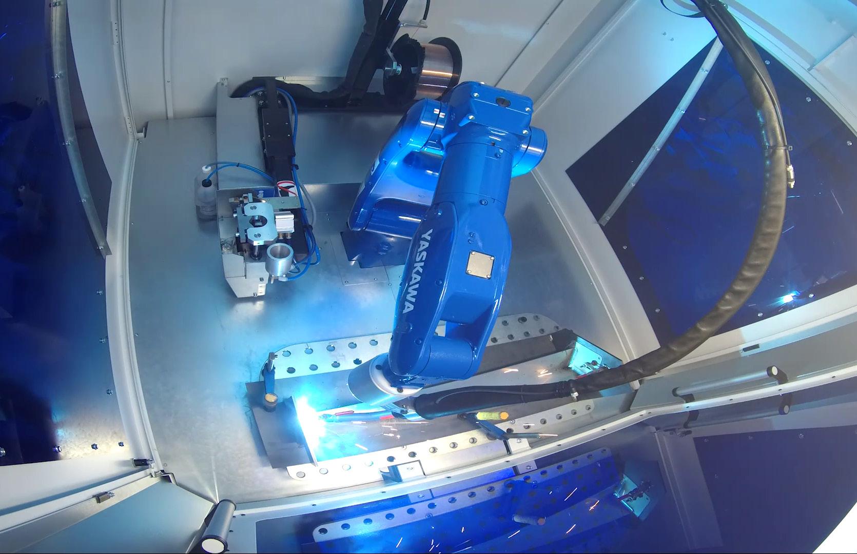
Cover Story: The ArcWorld standard systems available from YASKAWA are ideal for replacing or supplementing manual welding required in metal manufacturing applications. p.6 (Cover image: YASKAWA) Circulation Tel: +44 (0)1732 359990 Email: subscriptions@imlgroup.co.uk 10,000 Average net circulation Jan-Dec 2019 Connect with us on LinkedIn. Join us on Twitter. Follow us on Instagram.
Paige West, Group Editor
Ultra-compact, self-contained robot welding systems

Exploring the benefits of using robotic systems across a wider range of manufacturing applications has accelerated recently, where investment in the most up-to-date systems is making a significant contribution to maximising efficiency. Welding applications are a good example, and the availability of new, highly flexible, space-saving systems is helping manufacturers to integrate robotics into their welding and fabrication processes.
Less space, more output is not sur prisingly high on the ‘wish list’ for any forward-thinking manufacturer and the ArcWorld standard systems available from YASKAWA are ideal for replacing or supplementing manual welding required in metal manufacturing applications. These fully integrated systems offer the distinct advantage of being self-con
tained, so it’s a bit like buying any ma chine tool: you choose the size of ma chine you need and a location in which to install it and away you go.
The YASKAWA ArcWorld HS Micro and RS Mini systems are easy to install, op erate and relocate in a small footprint of either 2.3 sq. metres for the Mini, or as little as 1.4 sq. metres for the Micro. Both systems offer the possibility for operators to double their output with up to half the preparation time, compared to manual welding. The Micro system is supplied complete with robot and con troller and its hinged door opening pro vides lots of options, even though it’s a very small, compact system. The Mini system has a revolving door and table, which again means maximum flexibility within a compact system.
The systems are designed to allow quick changes of jigs, which is crucial in help ing to reduce the all-important set-up time and improving production output, compared to conventional manual weld
ing practices. Furthermore, creating im proved operational consistency by never missing a weld and ensuring the same quality of weld at the end of the shift as at the start, also means reduced ‘spat ter’, which improves the capacity for fettling.
Both systems incorporate a MOTO MAN-AR900 robot with a YRC1000 con troller, a start/stop button panel, and a fume extraction hood. They also feature a platform and casing with dark green polycarbonate glare shield protection and CE marking.
The Yaskawa Motoman ArcWorld Micro and Mini robotic welding systems repre sent the latest generation of cost-effective automated solutions for welding applica tions – and are pre-engineered, pre-as sembled and shipped ready to weld. They can also be configured with your choice of welding power source and are ready to mount your component tooling.
https://www.yaskawa.co.uk/
6 dpaonthenet.net Cover Story:Cover Story: Robot welding systems


201271 Contact: YASKAWA. Tel: +44 (0) 1295 272755 www.Yaskawa.co.uk ArcWorld Micro & Mini Ultra-compact, Self-Contained Welding Systems Less space, more output is probably high on your production ‘wish-list’ and we can help you make it happen with our fully integrated welding systems to supplement, or replace your manual welding applications. They offer the distinct advantage of being totally self-contained, so it’s like buying any machine tool – choose the size of machine you need, decide where to install it and away you go. Key Benefits ● Supplied complete with robot, controller and welding power source ● Easy to install, relocate and operate ● Small footprint (1.4 or 2.3 sq.m) ● Glare shield protection and fume extraction hood More at: https://bit.ly/3vgbEKI Delivering a flexible, space saving and cost-effective option to integrate robotics into your welding processes. www.arcworld.eu Cells from £39k
Is roller screw technology still underappreciated?
So, in examining the major selection concerns, here is how the roller screw performs…
When designers consider the options for controlled linear motion, do they fully ex amine the benefits that the roller screw offers in performance, in relation to hy draulic or pneumatic cylinders, as well as ball or lead screws? Roller screws have distinct advantages over these four other rivals in all of the major selection consid erations. Of course, each designer may have different selection criteria, which will be determined by the application.

If we take efficiency as the primary cri terion for selection, the roller screw is over 90 percent efficient, and, out of the five recognised choices, only the ball screw can compare. Life expectancy is very long for a roller screw, typically 15 times longer than a ball screw, and only the hydraulic or pneumatic cylinder options give similar service life; however, they both need maintenance to retain long life.
When it comes to maintenance itself, the roller screw requires very little main tenance as the friction created by the rolling screw design is minimal, com pared to that generated by sliding fric tion. However, the roller screw should
still be lubricated to minimise wear and dissipate heat. Providing sufficient pro tection against contaminants is also crit ical to long functional life, so wipers can be added to the front or back of the nut to scrape particulates from the threads throughout the screw stroke. Mainte nance intervals will depend on two main factors: the operating conditions and the screw diameter. By comparison, both hydraulic and pneumatic cylinders need much higher levels of attention, and ball screws can suffer from pitting in the ball groove, whilst the ball bearings can be lost or need replacing.
The load ratings of a roller screw can only be matched by a hydraulic cylinder. In performance, roller screws have, in some specific applications, been able to move up to 20,000 times their own weight, so are capable of carrying great
8 dpaonthenet.net
Even though the very first patent for a roller screw was granted in 1949, why is roller screw technology a less recognised option than other mechanisms for the conversion of rotary torque into linear motion? Mark Moore of Moore International Ltd explains their advantages.
Feature: Roller screws
er loads in relation to their size. They are also very suitable to carry heavy loads for continuous duty and in the most ar duous of conditions. The combination of speed and acceleration can only be equalled by that of a pneumatic cylin der. Both the stiffness and the effects of shock loading also make the roller screw an attractive option.
Automated industrial production lines are being designed to be more com pact systems that take up less space. One of the biggest advantages of the roller screw is that it requires only min imal space as it is much more compact and easier to install than hydraulic or pneumatic cylinder alternatives, both of which can be very complex and expen sive to fit. At the same time, the roller screw achieves considerably better po sitional accuracy than a ball screw.
Environmentally, the roller screw is less noisy in operation, which compares well to pneumatic systems, but also has the obvious advantages of leak-free func tionality (air and hydraulic fluid) and less power consumption.

The return on investment by purchasing roller screw technology is offset through total cost of ownership and life cycle costs. It is realised through the reduc tion in the cost of maintenance, early replacement, and resulting downtime.
How do roller screws function and what are the options?
Roller screws use rollers to transmit force from the nut to the shaft. The main elements are the screw, the nut, and the satellite rollers. Moore International sup plies the ROLLVIS Swiss range of roller screws which are used to transform ro
tary movements into linear movements and vice versa. The rolling elements are threaded rollers between the screw and the nut. The high number of points of contact enables satellite roller screws to support very heavy loads.
The ROLLVIS range comprises satellite roller screws with no recirculation (RV and HRV types), inverted roller screws (RVI type), differential roller screws (RVD type), and screws with recirculating roll ers (RVR type). Bearing units are also proposed to equip the different roller screw designs.
The RV screw is a high-precision, robust assembly where the rollers do not recir culate, thus enabling a very stable driv ing torque. Special gears are designed on the rollers and nut to maintain good kinematics, even in the most severe con ditions. The internal thread of the nut is identical to that of the screw. To ensure no axial movement occurs between the nut and the rollers, there is a single-start thread with precise angle accuracy be tween the nut and the rollers.
The RVR roller screw is a design that incorporates recirculating rollers. The rollers are guided within a cage and their motion is controlled by a set of cams. This design combines extremely high positioning accuracy, resolution and stiffness, while capacity ratings are at the highest, thanks to a robust thread geometry. This concept is perfect for all applications that need a very high accu racy under small or moderate speeds.
The RVI roller screw is an inverted roller screw. Whilst it is based on the same principle as the RV design and deliv ers exactly the same level of opera tional performance, the rollers do not move axially along the shaft and stroke is travelled within a longer nut. This concept follows specific design rules which enable higher capacity ratings with smaller leads. This consequently reduces the driving torque, optimises compactness, and makes a direct guid ing of the shaft possible.
The RVD roller screw is ideally suited for high-precision applications, when high accuracy is required. Its components are specifically designed and adjusted to allow extremely thin leads, down to 0.02mm. Shorter stroke applications are best suited for this type of roller screw.
The HRV roller screw is designed for very high load applications and for ex tended life. This design provides more contacts in the assembly than the RV type and has a different thread profile. The nuts are also longer than in the standard RV version. The HRV series is suitable for larger diameters and, con sequently, the range is not available in split nut format or with internal preload. Only standard or reduced backlash op tions are available.
https://www.mooreinternational.co.uk/
About the author: Mark Moore started his career in bearing distribution in 1983 but started his own company in 1997, focusing on linear motion technology and specialists in ball, roller and lead screw solutions. To complement these solutions, Mark built up a CNC machine shop to make custom nuts, as well as machined components, for customers.

Feature: Roller screws dpaonthenet.net 9
Putting prosthetic hands in motion
they relate to the operation of the pros thetic hand. The opening and closing of the palm translate into a requirement for a number of cycles per day, and 100-500 cycles might be typical. Then there is the time taken to actuate the hand to grip an object – the cycle time. For high-speed gripping, this might be 1-2 seconds. This will imply an actuation speed (the move ment of the fingers) of perhaps 12-15mm/ sec. The holding force is another consid eration, perhaps in the range of 30-80N. If the prosthetic is to be battery operated, the supply voltage and current must also be considered.
The linear speed of the actuator depends on the weight of the object the user is han dling. Higher linear speeds allow the user to grasp objects quickly. The force and speed depend on the designer’s choice of motor, gearbox, and the size of the lead screw used for the linear actuator.
derpinning this functionality is a mecha tronic system that combines high power density with optimum performance, ad dressing considerations for efficiency, re liability, accuracy, size, noise, and overall weight.
Chetan Kale, R&D Engineer at Portescap, discusses how standard motion solutions can meet all of these requirements in packages that also offer long battery life and low maintenance.
Prosthetic technology has developed enormously in recent years, with a hand amputee, for example, today being able to receive a prosthetic that will replicate a whole host of normal hand functions. Un

Based on the essential prehension re quirements of the given prosthetic, a 180-degree linear actuator is the start point for each of the motion elements. Such an actuator will typically comprise a motor that transfers the rotary motion to a lead screw by using a spur gear pair. The lead screw is attached to one spur gear and transfers motion to the piston which has internal threads. The piston moves forward and backward, due to the screw and nut mechanism between the lead screw and the piston. This linear motion of the piston is what creates finger actuation.
There are several key parameters to con sider within this integrated solution, as
Selection of the motor/gearbox combi nation is no trivial task, with the designer needing to find the right balance of perfor mance characteristics to ensure the prop er holding force and linear speed neces sary for grasping, while also optimising the package for the available space and required battery life.
Electric motor selection
Motor regulation is a critical parameter of the motor which defines speed-torque characteristics. Lower motor regulation results in a more powerful motor, but it is important to remember that as torque (load) increases, speed decreases. The speed drop rate is less in the case of better motor regulation. Good motor regulation provides high power density, leading to fewer power losses and better efficiency.
Coreless brush DC motors provide an ideal solution. Affording the required good
10 dpaonthenet.net
There was a time
when
a hand amputee would have been asked to use a hook prosthesis that had limited functions and carried a significant amount of social stigma. Today, designers are looking to build prosthetics that are not only functionally efficient, but also durable, comfortable, lightweight, and aesthetically pleasing. Feature: Motion solutions
Prosthetic technology has developed enormously with a hand amputee being able to receive
a
prosthetic that
will
replicate
a whole
host of normal hand functions
motor regulation, they are also highly effi cient, reliable, and cost effective. A core less brush DC motor, with its incorporated gearbox, operates at low noise, and offers high power density. This ensures optimum space utilisation and low weight, with the motor able to meet not only the mechani cal performance criteria of the application, but also the size and portability require ments of the prosthetic. A lighter motor reduces the overall weight of prosthetic hands and helps the user to use the pros thetic with minimum effort.
For accurate positioning and motion con trol, a suitable encoder is recommended for use with the motor and gearbox. Mo tors with integrated gearboxes and en coders enable the user to move fingers more nimbly to grasp objects. Magnetic encoders provide a high degree of ac curacy that is ideal for prosthetics appli
Optimisation of the mechatronic pack age for prosthetic hands is a delicate balance of different (and sometimes con tradictory) performance requirements.

For the designer, it can be enormously beneficial to collaborate with a motion technology supplier who can help in tailoring or customising the package to
Motion solutions
provide the best fit. With expertise in all the technologies discussed, and the know-how to bring them all together to provide an enhanced mechatronic pack age, Portescap can help bring a pros thetic application to life.
www.portescap.com
Take a look at the future of automation Your first step towards switching to robots
Robotic manufacturing and logistics solutions are opening new possibilities to satisfy the demands of today’s consumers for fast delivery of a wide range of personalised goods.
Visit our virtual stand at https://bit.ly/ABB_PPMA2021 to explore our full offering for automated packaging and processing. If you are visiting the 2021 PPMA show, you can also meet us at stand E100 from Tuesday 28th September – Thursday 30th September 2021 at the NEC in Birmingham.

Feature:
About the author: Chetan Kale is R&D Engineer at Portescap.
—
Lubrication monitoring solution for linear guides prevents unplanned downtime of vehicle handling systems
By installing the Schaeffler DuraSense lubrication monitoring solution on its vehicle handling systems, automotive machine maker Hager Sondermaschinenbau GmbH has seen a range of benefits, including the prevention of unplanned downtime due to insufficient lubrication, extended time intervals for general overhaul, and early detection of defective lubricators.
Hager is using the DuraSense lubri cation monitoring solution on linear axes in large portal handling systems, which are being developed for car body production at major automo tive manufacturers around the world. Hager intends to use this solution to reduce unplanned downtime for its customers on their production lines.

12 dpaonthenet.net
Feature: Lubrication monitoring solution
Challenge for Schaeffler
Hager produces portal handling sys tems that weigh up to 90 tonnes, for renowned automotive manufac turers. The maintenance, general overhaul and assembly of the portal handling systems is undertaken by around 80 employees at its site in Möttingen, Germany.
In 2012, Hager designed a new type of clamping frame replacement sys tem for car production. The KFG3 portal handling system, also known as a framer, moves vehicle clamping equipment (clamping frames) with the aid of linear axes. Up to 50 vehi cles per hour can be produced using the KFG3. The monorail guidance systems used in the linear axes are considered among the most sys tem-critical components in the fram er. If these fail, the entire production line is shut down. For this reason, Hager was searching for a moni toring solution that could not only be retrofitted to the linear axes, but which the company could also use to optimise the general overhaul in tervals. As a result, Hager decided to seek assistance from Schaeffler.
Schaeffler solution
Experts at Schaeffler recommended DuraSense as a monitoring solu tion for the linear axes. The system comprises carriages with sensors developed specifically for this task and a pre-processing unit for up to seven acceleration sensors. The pre-processing unit at the heart of DuraSense contains Schaeffler’s roll ing bearing expertise, evaluates the sensor signals, and generates an au
thoritative lubrication parameter. The vibration energy that is emitted by the carriage is influenced by ageing lubricant or a decreasing lubricant volume, and DuraSense makes use of this effect. The determined lubri cation parameter describes the cur rent lubrication condition of the car riage and DuraSense sends a signal to the machine control system if the lubrication limit value is exceeded. DuraSense also detects the exact time for relubrication.
Customer benefits
The DuraSense monitoring solution is an important tool for Hager in preventing unplanned downtime of portal handling systems. Other ad vantages include:
• Early detection of defective lu bricators and clogged/leaky lines
• Predictable maintenance work and reduced workload for per sonnel
• Longer-term planning of re placement parts procurement and substitution
• Extended time intervals for a general overhaul
• DuraSense can be retrofitted to existing systems

• Unplanned downtime, due to insufficient lubrication of linear axes, is reduced.
Michael Hager, Executive Director at Hager Sondermaschinenbau GmbH and a qualified industrial engineer, summarises the benefits of the Dura Sense solution: “With the monitoring system from Schaeffler, we have found a solution that is easy to integrate and
will enable us to acquire knowledge about the wear behaviour of our plant with every system installed.”
Stefan Schneider, Technical Manag er for Mechanical Systems at Hager Sondermaschinenbau GmbH, com ments: “DuraSense can unlock huge cost-saving opportunities. With just one system, we can identify all sources of defects that lead to incorrect lubri cation.”
“With Schaeffler DuraSense, both in sufficient lubrication and over-greas ing are reliably prevented, resulting in lubricant savings of up to 30 percent, achieved at optimum load, as well as reducing the number of failures caused by contamination,” Sally Sil lis, Technology Centre Manager at Schaeffler UK, says. “DuraSense re liably monitors the lubrication condi tions of each carriage in linear axes. Relubrication only occurs when it is needed and in the right volumes, so there is no risk of over-greasing. This, in turn, means a cost reduction for operating supplies, which also helps preserve resources and the environ ment. The system also verifies that the lubricant actually ends up inside the carriages. Individual monitoring of each carriage means that any problems, such as a loose grease hose, can be localised easily.”
For more information on DuraSense, please contact Schaeffler UK’s Com munications & Branding Department: info.uk@schaeffler.com https://www.schaeffler.co.uk/ content.schaeffler.co.uk/en/index.jsp
Ask Hammond to customise any of our 5000+ standard stocked enclosures to your requirements Learn more: hammfg.com/mods uksales@hammfg.com • 01256 812812 Feature: Lubrication monitoring solution
Fine lines: A guide to linear guides for robotic applications
on systems consisting of linear guides to weld parts together accurately.
More and more, robots are seen as the answer to many of the manufacturing and engineering industry’s challenges. From higher productivity to overcoming skills shortages, through to increasing automation and even combatting the pandemic by allowing more workers to change to remote working, robots are key to the ongoing Fourth Industrial Revolution.
Valued at USD 39.72 billion in 2019, the robotics market is expected to register a CAGR of 25.38 percent from 2020 to 2025, according to Mordor Intelligence. In the past, robots have generally been seen as high outlay capital assets with a slow ROI, but growth is expected to move from large, costly robots to much smaller col laborative robots (cobots). Often, these
cobots are much more attainable with much shorter payback time frames, due to declining sensor prices, component costs, and increasing adoption.

One such group of components that is crucial to future adoption are linear guides and rails. It is vital that engineers consider these components wisely, and look at not just cost, but everything from performance and accuracy to longevity and future maintenance needs.
A linear approach to finding the right linear guides
To enable robots to perform tasks day in, day out, and move as quickly and precisely as possible, many rely on line ar guide systems. For instance, welding robots in the automotive industry rely
Choosing linear guides is based on the application, machine structure, mount ing space, operating environment, load, speed, stroke, accuracy, and required lifespan of the component.
Of those factors, mounting space and accuracy arguably play the largest parts in selection. norelem offers the com plete package for solutions, from profile rail guides, suitable guide carriages, plastic slide guides with matching guide carriages, and more. These compo nents do not correspond to any DIN (i.e. they are not a standard part) but are standardised components in which the dimensions are adapted to adjacent components.
Linear guide accuracy class also plays an important part in the bearing’s trav el behaviour, which is the performance characteristic that most people associ ate with the term ‘accuracy’. Regardless
14 dpaonthenet.net
Engineers and manufacturers are increasingly turning to robots for increased productivity, and key to these engineering marvels are linear guides. Martin Ahner, Head of norelem ACADEMY, discusses the considerations required when choosing these components.
Feature: Robotic linear guides
of size, preload, or mounting configura tion, parallelism between the reference edges of the rail and the block ultimate ly determines the travel accuracy of the guide system. This parallelism tolerance specifies how the bearing block will be have positionally as it moves down the rail.
Choose the wrong linear guides and the bearing block may deviate, either going up and down or side to side as it trav els along the rails. For robotics, where accuracy is key, this simply cannot be allowed to happen. norelem’s wide range of linear guides provides a variety of accuracy classes, suitable for many applications.
Engineers can also use compact linear ball bearings, which are available with or without a self-aligning function. Reg ular steel versions from norelem have a plastic cage, whereas the self-aligning models are made up of a plastic hous ing, with runner plates, allowing them to correct misalignments, to compensate for tolerances and prevent tilting.
Robust linear guides create robust robots
Along with mounting and accuracy, engineers must also duly consider lifespan, maintenance and servicing of linear guides. These components must be able to withstand the environment they are deployed in, for a long and trouble-free life and to minimise robot downtime.
Certain precautions should be taken for different environments. Due to the recir culating rolling elements, linear guides should be in as clean and as debris-free an environment as possible. If dirt gets on the rails, the rolling elements may lose their lubrication, and as such, inter fere with the travel speed and accuracy. This compromises the whole operation of the robot.
While a clean environment cannot be guaranteed at all times, an upgraded lubrication option can be added to a linear guide to help increase the lifetime of the guide in a dirtier environment. The linear guides can also be protected with linear housing units, such as those
in norelem’s range, to prevent dirt and dust from getting onto the bearings.
To make maintenance and servicing easier, housing units have a greasing hole to relubricate the bearings when required.
As relatively large capital investments, it is also important to house robots effectively, so that they do not suffer from any unwanted damage or debris that could affect their performance. To this end, a simple but effective method is to use aluminium profiles to build a barrier around the robot. Along with aluminium profiles, norelem provides a complete range of other assembly com ponents, like covers, pull handles, grips and hinges, to help create the optimum housings.
Make downtime a thing of the past
As mentioned, any downtime must be negated to ensure robots are efficient and generating the return required. This is even more so the case if the robot is part of a production line – any long pe riods where the robot is inoperable can jeopardise the whole facility’s operation.
In addition to protecting the robot and linear guides with effective housing components, predictive maintenance intervals can help to shorten downtime. Standstill can also be avoided by con dition monitoring, which is why norelem

has been developing standard compo nents that can show premature wear, for instance in clamping components.
It is also advisable to use components that are readily available and accessi ble. Often, bespoke components can be costly and time consuming to repair or replace, especially if they need spe cialist engineers to fix them or the parts need to be custom ordered and re manufactured. Standard components, though, can be easily accessed, and delivery can be as quick as next day, meaning downtime should no longer be a concern.
Leading the way to a robotic future
Robots are undoubtedly going to be the future of engineering and manufactur ing. To lower the barriers to entry, par ticularly for small-to-medium enterpris es, costs must be kept in check, while creating and maintaining the asset must be simple and easy.
With standard components like linear guides and accessories such as hous ing components, this is no longer just a pipe dream. norelem has experts in plant and mechanical engineering at hand, ready to assist in any robotics projects and application requirements.
For more about norelem, please visit www.norelem.co.uk.
About the author: Martin Ahner is Head of norelem ACADEMY, which is a part of norelem. norelem ACADEMY promotes young talent, and provides free expert talks at educational institutions as well as funding a variety of promotional projects.
With a degree in mechanical engineering, Martin has been with norelem for five years and is frequently seen at global trade shows and exhibitions, assisting customers and new engineers looking to progress in the industry.
Feature: Robotic linear guides dpaonthenet.net 15
Ewellix planetary roller screw lands on Mars
Ewellix engineers worked in collaboration with NASA’s Jet Propulsion Laboratory (JPL) at the California Institute of Technol ogy, to develop a roller screw component

for the Perseverance Rover that would be robust enough to withstand the extreme conditions of outer space and Mars, which can reach -80ºC.
After a 203-day journey, the Persever ance Rover, the largest and most ad vanced rover NASA has sent to another planet, has touched down on Mars to search for signs of ancient microbial life. The Rover’s mission is to collect Martian rocks, and extract and seal samples for testing and onboard stor age. The mission team of NASA scien tists will then decide when and where the Perseverance Rover will leave the samples for pick up by a future mission in approximately 2031, to bring them back to Earth for detailed analysis.
Ewellix’s planetary roller screw is housed inside the sealing station on the base of the Perseverance Rover and
16 dpaonthenet.net
Ewellix has developed and manufactured a planetary roller screw that recently landed on Mars
as part of
NASA’s Mars 2020 Perseverance Rover Mission. Feature: Planetary roller screw
Ewellix planetary roller screw as per the one adapted for the Mars 2020 Perseverance Rover Mission. (Source: Ewellix)
will generate the high force required to seal hermetically the 43 sample tubes on board. The Rover has a small servo motor that drives the roller screw nut. This rotational movement is converted into a linear displace ment that pushes on a ram, which, in turn, presses the seal inside the open end of the sample tube with extremely precise force, speed and position.

It was critical to save mass on the Rover, and Ewellix’s roller screw pro vided a tremendous amount of force load in a small mechanism, making it an ideal rover component for load rating and weight. Other benefits are long service life by design, high reliability, and the ability to withstand fre quent changes of loading direction, high linear speed, and some amount of contamination.


Ewellix’s planetary roller screw is a fully customised version of a standard SR/HR planetary roller screw product. All parts and materials have been adapted for the unique conditions through extensive analysis and testing. Adaptations include aerospace-grade materials and heat treatment oper ations provided by suppliers with aerospace certifications.


This unique planetary roller screw took several years to develop, proto type, manufacture and test, from concept exploration to system valida tion, where one of the final product samples Ewellix provided was select ed for the mission. Extensive system testing, including the roller screw, was performed at JPL in California.

Jean-Pierre Collognat, Project Lead and Business Development Manager at Ewellix, explains some of the challenges of the project: “There were certainly some firsts for us along the way, due to challenging application conditions and environment and the need to downsize our components as much as possible, to reduce space and weight, yet still optimise the load rating and reliability. Plus, all materials have to work at all times at extremely low temperatures, hence all of the component materials were subjected to specific heat treatments.


“Ewellix has taken precision engineering and manufacturing to new levels on this incredible project, showing how a catalogue mechanical product can evolve into a unique component for use, quite literally, in another world.”


https://www.ewellix.com/en/global/ dpaonthenet.net 17 Feature: Planetary roller screw Touchdown of NASA’s Mars 2020 Perseverance Rover Mission that was carrying Ewellix’s Planetary Roller Screw. (Source: NASA) Taurus Range of Standard RF Connectors RF and Microwave Connectors, Adaptors and Cable Assemblies www.intelliconnect.co.uk A different kind of Interconnect Solutions Provider For further information, please call us on +44 (0) 1245 347145, email sales@intelliconnect.co.uk or visit our website. Brand new range of low cost, high quality standard coaxial connectors and adaptors Available from stock on a 1–3 day lead ti me Taurus connectors are provided with the same high level of quality controls as our market leading Precision and Pisces ranges BNC, TNC, N Type, UHF, Mini UHF, F Type, FME, SMA, SMB, SMC, SSMA, SSMB, SSMC, MCX, MMCX and Inter Series Adaptors IntConn_Taurus_Electronics.indd 1 19/05/2020 15:52
How static motor testing can support preventative maintenance programmes


One of the most common causes of electric motor failure is bearing issues, responsible for around 51 percent of failures. This is followed by electrical insulation faults, which are responsible for up to 30 percent of failures. But, while predictive maintenance techniques, such as vibration analysis, are often used to analyse the motor’s health, in comparison, little is done to detect signs of insulation deterioration and failure.
Here, Chris Robson, Sales Director of Houghton International, discusses the importance of static motor testing for assessing the full condition of motors.
The problems caused by insulation deterioration can be just as serious as those caused by worn bearings or overheating. Engineers can use die lectric testing, a non-intrusive condi tion monitoring technique, which can be carried out as part of an inspection or planned overhaul. These tests are designed to assess the condition of a motor’s windings and to diagnose and
predict any early signs of deterioration and ageing. As a result, these tests allow operators to schedule repairs ahead of a failure, which can often be very costly and result in unplanned downtime.
Static motor testing
To check the motor’s insulation system and give an overall picture of its health, static or offline testing is a good option. This is performed while the motor is not running and can be executed on site or in a specialised electric motor repair facility. These tests are routinely carried
out to determine the integrity of the windings and demonstrate that a motor is correctly wound and insulated.
On-site testing is routinely implemented once or twice a year, or during scheduled outages. Recommendations on how of ten tests are undertaken are based on a range of factors, such as criticality, history, size, repair costs, availability of spares, daily starts and stops, and ease of access – amongst others.
Houghton International uses a Baker DX series and 40kV power pack PP40 test
Feature: Static motor testing
Rittal & Eplan: Your partners for sustainable panel building and switchgear manufacturing.
er to apply a wide set of offline electrical tests, to assess the condition of motors and coil windings.
The Baker DX can find early indications of insulation weakness and faults in windings – between phases, coil-to-coil and in ground-wall insulation. The tests can identify if contamination is impacting insulation strength and detect problems with connections, such as feed cable insulation weakness, motor imbalances, and open or high resistance. Houghton International also offers periodic offline testing and trending of the motor’s insu lation systems, on site or in its workshop, to give an overall picture of motor insula tion health.
A complete diagnosis of the insulation system also includes a winding resist ance test, an IR megohm test, a polari sation test, a step-voltage or high poten tial test, and a surge test – all carried out using the Baker Tester. For higher volt age motors (6kV and above), partial dis charge testing can also be used to pro vide a wider picture of the asset’s health.
Partial discharge
High-voltage equipment often suffers from partial discharge activity, where lo calised corona or breakdown discharge can damage insulation, leading to pro gressive degradation and eventual in sulation breakdown. This type of issue would not be detected using standard diagnostic tests and it is even possi
ble for a motor to appear healthy while having high levels of partial discharge. Compared with other dielectric tests, the differentiating character of partial dis charge measurements allows localised weak and aged points of the insulation to be identified.
Partial discharge testing and monitoring are particularly important when the asset is critical to the operation of a network; this may be due to the asset’s age, past failures, or the financial consequences of a failure. Partial discharge measure ments based on IEC 60034-27 stand ards can be performed on motors and generators either online, during regular load service operation, or offline.
All tests should be carried out in accord ance with appropriate standards such as IEEE, IEC and EASA standard AR1002105, which outlines recommended
Feature: Static motor testing

practices for the repair and therefore the testing of rotating electrical apparatus.
Static motor testing enables machin ery operators and plant owners to get a full picture of the motor’s health and make informed decisions about their equipment’s future. Successful testing requires high quality, calibrated equip ment, and highly trained and competent engineers to provide quality results and reduce the downtime of the assets.
Houghton International provides a wide range of online and offline motor testing options, including dielectric and partial discharge testing, at your premises or in the company’s repair workshop. To find out how Houghton International can support your ongoing electric motor maintenance activities, get in touch with its expert engineers at www.houghtoninternational.com.
About the author: Chris Robson is the Sales Director at Houghton International. He recently joined the board of directors, following 10 years at Houghton International in various roles, and brings a wealth of experience in both engineering and sales. Starting as a fitter in the Electro-Mechanical Services division, Chris went on to manage the department before joining the sales team in 2014. Most recently, he has been responsible for sales in the Rail Services division, delivering growth of 20 percent and a number of multimillion-pound projects.

www.rittal.co.uk - www.eplan.co.uk
Factors to consider when measuring thickness in battery production
Energy storage devices, such as lithium-ion batteries, play a crucial role in electromobility and energy transition. In order to optimise battery production, sensors are required to monitor the production line, including thickness measurement sensors. But Glenn Wedgbrow, Business Development Manager at MicroEpsilon UK, asks, what are the challenges in making reliable thickness measurements?
The growing demand for energy storage devices, such as lithium-ion batteries and fuel cells, is being met by Giga fac tories that are equipped with efficient, highly automated production technolo gies. Sensors are required to monitor the production line to the highest accuracy and dynamics. These sensors include high-precision distance sensors, infra red temperature measurement technol ogy, as well as 2D/3D profile sensors for
the many measurement tasks involved in battery production, such as electrode manufacturing, assembly and forming processes.

In battery production, one of the key quality control parameters is the thick ness (and width) of film and strip mate rials, wet layers, and electrode coatings. These require sensors that measure thickness reliably as the material is be
ing processed (inline) – helping to opti mise production yields, while minimising waste. All manufacturers will have a process specification that they will need to meet, to satisfy their customers. But how can a manufacturer be sure that they are meeting these specifications at all times and what are the challenges they face?
A number of different measurement systems can be used to measure the thickness of a material. Some of these are used offline, i.e. random samples of the material are removed from produc tion and measured, to verify that they meet the specification. A more effective approach is to install an in-process or fixed inline non-contact measurement system that continuously measures the thickness of the material as it is pro
To optimise battery production, sensors are required to monitor the production line to the highest accuracy and dynamics 20 dpaonthenet.net
Feature: Battery optimisation
cessed. If measurements from these systems move towards the outer limits of the specification, machine and pro cess control parameters can be altered to bring the thickness back into accept able limits.

Real-world errors
A key factor to consider when selecting a suitable system from a supplier is to understand the combined real-world errors that can occur when using a non-contact thickness measurement system, and how these errors can be compensated for or eliminated. While many suppliers state on their datasheet that the measurement system meets a certain resolution and linearity, in the real world, this performance is affected by a number of environmental influenc es. Errors associated with real-world thickness measurement are not always so obvious, but can combine to create significantly large errors. It is therefore critical to select a system based on sys tem accuracy, not just sensor accuracy.
Alignment & target movement
Special attention must be paid to the alignment of the sensors, which are typ ically installed opposite one another. No misalignment, tilting or inclination of the sensors relative to the target object is permissible, to ensure the sensor spots are measuring at the same point all the way through the measurement range. For example, for a misalignment of 1mm and an inclination of 2°, there will be a thickness measurement error of 35µm. In the case of a 10mm target thickness, this error increases to 41µm.
Combined linearity errors of up to 8µm, for example, can be seen with a vertical target movement of just 200µm of the target in the measurement field, even if the target has the same thickness. The combined error of non-linearity must therefore be compensated for from both sensors. As a supplier of non-contact inline thickness measurement systems, Micro-Epsilon has developed its own methods of precise sensor alignment and patented algorithms for this process.
Synchronisation
To avoid thickness calculation error due to movement of the target, both sensors
must be perfectly synchronised so that they perform the measurement at the same time, at the exact opposite point of the target. If synchronisation does not occur, inaccurate measurement data is produced. For example, if measure ments are taken at different time inter vals, micro-vibrations of the target or the sensor mechanics will result in a thick ness measurement error. For example, for a time-delayed measurement of 1ms, a deviation of 125µm is produced (assuming 1mm vibration at 20Hz).
Individual sensor accuracy/ linearity
Each measurement sensor has its own measurement uncertainty, often referred to as ‘linearity’. This means that, at any given point in the measuring range, the actual reading from a sensor can vary by a percentage of its measuring range. The challenge is that no sensor is the same, so errors caused by non-linear ity can add or subtract in the final re sult. Micro-Epsilon has overcome this challenge by performing a combined, patented calibration of both sensors to create a new, significantly improved thickness measurement linearity.
Thermal behaviour of sensors and/or mounting frame
It is extremely important to design a me chanically and thermally stable sensor mounting frame. The mounting mecha nism should be isolated from process or machine vibration as best as possible. Mounting with an O-frame is more sta
ble than using a C-frame.
Thermal expansion of mounting mate rials is often overlooked as a source of large errors in precise thickness meas urement. Therefore, selecting materials with as low a thermal expansion coef ficient as possible is very important. For example, by mounting sensors on a typi cal aluminium or stainless steel extruded profile, with a thermal expansion coeffi cient of ~16ppm/K, experimental testing has shown that just a 5°C change in am bient temperature can move the sensors by >80µm! In contrast, using a standard grade Invar mounting frame with a ther mal expansion coefficient of typically 1.2ppm/K reduces this to 6µm. Special ist Invar grades can reduce this error by half again, but they can result in a very expensive solution and do not solve the problem when the manufacturing tolerances can be single microns, as is often the case with battery production. Micro-Epsilon has solved this issue with integrated automatic thermal compen sation, to eliminate measurement errors due to thermal expansion.
In addition, Micro-Epsilon inline thick ness measurement systems provide automatic calibration features built into their system as standard, which provide gauge capability results at the touch of a button. This also means the operator does not have to spend time calibrating and checking the system.
https://www.micro-epsilon.co.uk/
About the author: Graduating from the University of Central England with a 1st Class Honours Degree in Engineering, Glenn Wedgbrow has over 25 years of experience in the engineering industry. Specialising in precision sensor measurement technologies, Glenn has been delivering measurement solutions including position, movement, temperature and colour inspection to all industries throughout the UK & Ireland. With in-depth knowledge and expertise in solving measurement applications on almost all materials with the use of innovative sensors and systems, Glenn has provided numerous solutions for leading multinationals, and medium- and small-sized businesses, liaising with design engineers and UK manufacturers in almost all industries –from metal, rubber and plastics to automotive and aerospace.
 In battery production, one of the key quality control parameters is the thickness (and width) of film and strip materials, wet layers, and electrode coatings
Feature: Battery optimisation dpaonthenet.net 21
gauges
HBK strain gauges measure vibration of new pile driving method for offshore wind turbines

Dutch installation specialist, GBM Works, is developing a new method to reduce the noise pollution caused by driving foundation piles for wind turbines into the seabed.
This method involves fluidising the sea bed with water jets, which ensures the monopiles sink much more quickly – and with significantly less noise – under their own weight. To assess this new system at the Maasvlakte site, tests were carried out to measure the monopiles’ vibrations and deformations, using strain gauges supplied by HBK.
Ben Arntz, Founder and Director of GBM Works, explains: “Driving foundation piles for wind turbines into the seabed causes vibrations, pressure waves and –in particular – also a great deal of noise. When a steel foundation pile with a diam eter of eight metres is driven, the noise production can reach … up to 180 deci bels. The vibrations, the pressure waves and the loud noise have a negative effect on underwater life. Therefore, regulations have been adopted to reduce the noise production of pile driving activities at sea. International guidelines are expected to become stricter in the coming years. Our new method responds to this.”
Mr Arntz continues: “On the inside of the pile, dozens of water jets spray seawater into the seabed. As a result, the seabed takes on properties comparable to those of quicksand. The resistance of the sea bed decreases, and the foundation pile sinks into the seabed. The second part of the solution is a vibratory hammer that replaces the hydraulic pile driving rig. In a traditional pile driving rig, a steel pile hammer strikes a foundation, made from the same material, which produces a
great deal of noise. The vibratory ham mer consists of rotating disks mounted on top of the monopile. These cause the monopile to vibrate, so that it sinks into the fluidised seabed layer.”
A series of tests was conducted in Sep tember 2020. “The aim was, among other things, to collect information on the vibra tions that arise, the water pressure that is needed, the behaviour of the soil and, of course, the effect on noise damping. In all, 62 test installations were executed with four setups: two with the jet gun sys tem and the vibratory hammer, and two tests with the vibratory hammer alone on the same foundation piles. To measure the strain in the monopiles, GBM Works chose to use strain gauges from HBK. These strain gauges are often used to monitor wind turbines. When you exert pressure on steel monopiles, deformation occurs, and vibrations arise that cause noise. We measured those vibrations and also got some interesting information on fatigue in the foundation piles.’’
“Most of the data now has been ana lysed,” said Wouter Verschueren, Data
& Model Engineer at GBM Works. “We saw, for example, that the foundation piles with the vibratory hammer alone penetrated the ground no farther than three or four metres because the soil resistance became too high. With the jet gun and the vibratory hammer, the piles easily went to a depth of 10 me tres, while the speed at constant force quadrupled. In a subsequent test cycle underwater, the noise production of the solution with the vibratory hammer and the jet gun will be compared to that of a traditional pile hammer. A pile driving rig, in combination with a sound miti gation system, is currently used. These are complex systems that operate with an underwater shield around the foun dation pile to damp the vibrations and noise. GBM Works expects a noise re duction of 90 to 95 percent, thanks to the new system.”
It was recently announced that GBM Works will be granted a subsidy of ¤1.8 million by RVO for the development of a prototype of the equipment.
22 dpaonthenet.net
Feature: Pressure sensors
Strain
https://hbkworld.com/


More Precision Sensor system for precise inline thickness measurements Phone +44 (0) 151 355 6070 | www.micro-epsilon.co.uk | info@micro-epsilon.co.uk The new class for inline thickness measurements Compact complete solution for precise inline thickness measurements up to 25 mm Different sensor technologies for many types of surfaces & materials Traversing sensors on linear axis Fully automatic calibration IPC and thicknessCONTROL software included 24 VDC supply for the entire system Material engineering Thickness measurement of film,plastic plates, woven materials, wood & ceramics Energy industry Thickness measurement of fuel cells and battery film (coated and uncoated) Metal production Thickness measurement of metal film, metal strips and metal plates NEW thickness GAUGE
Taking on the data challenge in ADAS and autonomy
of the development process for au tonomous driving (AD) software and advanced driver-assistance systems (ADAS). It is often performed by under taking many thousands of simulation exercises – often in parallel, to minimise time to market.

To enable this rapid parallel testing, the test system must be capable of storing petabytes of test data that may reside on servers anywhere around the world. Furthermore, the test results and anal ysis must be made available to thou sands of engineering teams globally.

While many autonomous vehicles are expected to appear on our roads en masse in the next few years, it is now becoming apparent that the challenge is greater than many experts first thought. There are many challenges, and a significant proportion of these are related to safety – which is clearly an important matter, as people will be in vehicles over which they have little, if any, direct control.
Testing these vehicles needs to be ad equate to catch any defect and cover all possible driving situations – but how much testing will be required? In 2016, the RAND Corporation estimated that billions of kilometres would have to be driven – although, more recently, the
focus has been on the diversity of driv ing situations as opposed to billions of highway miles.
Ensuring diversity of miles
Due to regulatory standards, testing is an indispensable facet of all stages
Modern collaborative development platforms are required to encompass thousands of graphics processing units (GPUs) that are necessary to train the models. In addition, there can be mil lions of central processing units (CPUs) employed for data processing and val idation.
Autonomous vehicles (AV) will have to handle many scenarios, from city driv ing to highways and remote roads, as well as different weather conditions, some of which may obscure road markings. To assess the vehicle and its systems in all these scenarios, a comprehensive suite of tests will be required. While every aspect of the AV must be tested, particular emphasis will be put on the many algorithms relating to planning, perception, and decision making. Specific emphasis is put upon testing the machine learning percep tion algorithms with real-world data to ensure that they can function correctly in all environmental conditions.
Data unlocks the challenge
Possibly the greatest challenge in test ing new technologies such as the AV is searching for scenarios that can identi fy a weakness or problem. No person or machine can be expected to deduce every possible scenario that could exist
24 dpaonthenet.net
Feature: Autonomous vehicles
Figure 1: To test the right miles, cloud services and edge computing are often required to record and replay real-world data scenarios sustainably in ADAS/AD validation phases
in the real world – put simply, ‘we don’t know what we don’t know’. Therefore, there is no substitute for real-world driving to see what the world can throw at the AV.
Vehicles are driven extensively in dif ferent countries and conditions, so new scenarios can be identified and the data captured can be used to train algorithms and test for new real-world situations, thereby increasing test cov erages.
Modern vehicles contain hundreds of sensors and, as many of these sensors can be HD cameras, LiDAR or radar, the quantity of data from just a single sensor can be significant – and as test drives can last for several hours, the data set collected is generally huge. The process of data acquisition, syn chronisation and storage often entails coping with data rates in excess of 6Gbps. Data acquisition at these rates is forcing organisations to think again about how they manage it – ensuring that they are more intelligent about how they capture, store, manage, and use petabytes of data.
The challenge is further compounded by changing business and technical needs in the world of ADAS/AD devel opment which drive the need for fully agile data solutions. Additionally, as the vehicles in development continually re ceive enhancements and new features, future data management needs are somewhat unpredictable.
This unpredictability, along with the huge amounts of data involved, means that many organisations are now com bining their edge computing with cloud services such as Amazon Web Servic es (AWS).
Solving the data challenge
The data from real-world drives are es sential to the ADAS/AD development process and are captured with a sys tem that formats and synchronises all the raw sensor, inertial measurement unit (IMU), and CAN bus data.
Many data recording systems include some form of portable storage and can
interface with AWS edge computing solutions, including Snowball Edge or Snowcone. These devices are highly integrated into the Amazon platform and have the essential inbuilt security as well as up to 80TB of storage and the ability to pull data into Amazon Sim ple Storage Service (Amazon S3).
The AWS Snow devices are an excel lent way of transferring data from ve hicle-based data loggers to the AWS cloud service as they are secure, cost-effective and do not require a net work. The primary limitation is where higher data bandwidth is required, or the space and/or power available is heavily constrained. In these situations, portable media is generally considered the preferred solution.
Another approach is to use Amazon Direct Connect within a fixed location, such as a data centre or smart garage. This gives highly secure, high band width to connect with AWS at a low cost and with lower latency than other approaches. The approach can also be used for portable media – removing it from the vehicle and uploading it from the data centre/smart garage.
The key goal is to get the data onto the AWS platform quickly and securely so that team members (such as product developers, validation engineers, data scientists and others) can access it and carry out the necessary processing and analysis, and map the scenes from the drive logs to the test environment.

The challenge continues:
Replaying data
Once the petabytes of data are stored and analysed, the project team can
move on to the next challenge in the ADAS/AD development process –training and testing embedded code. This software validation process will entail replaying data as well as HIL test ing. Test coverage can be dramatically expanded by employing synchronised data replay and high-fidelity environ mental simulation within a common framework, to host extensive sets of data from sensors, support entire vir tual environments in systems such as AWS, send data streams to HIL sys tems (including those from NI), and conduct both replay and HIL testing. This approach ensures maximum test coverage, while managing project costs.
Bridging the divide between data re cording and replay is one of the key prerequisites for meeting test cover age goals. Alongside this, KPIs such as scalability, development effort and system cost must be monitored and balanced. NI strongly advocates cre ating partnerships between leading organisations (such as its partnership with AWS) as being the most success ful approach to developing the AVs of the future.
As NI is actively engaged with AWS to validate using Snow devices with NI data loggers, copy stations, HIL rigs, and other tools, NI customers are uniquely positioned with the flexibility and choice to determine their optimum ADAS/AD test and data solutions.
You can find out more here: https:// www.youtube.com/watch?v=eX_ cCx-DXc4
https://www.ni.com/en-gb.html
About the authors: Bryan Berezdivin, WW Industry Lead, Autonomous Vehicles, Amazon Web Services. Bryan has a strong background in protocol design, integration, and complex systems. Recent positions have focused on technical strategy, product management, and execution to provide access to adjacent markets. At Amazon, he works with customers to build and evolve autonomous systems with the power of cloud services for ubiquitous computing, AI, storage, networking, IoT, and to be defined solutions.
Nick Keel, Principal Offering Manager, ADAS Validation, NI. Nick has been part of NI for 12 years. A graduate of Electrical and Electronics Engineering, he drives the strategy for NI’s growth in ADAS and autonomous vehicle testing, collaborating with cross-functional teams to design solutions for testing active safety and autonomous vehicle systems.
Feature: Autonomous vehicles dpaonthenet.net 25
Figure 2: Data recording systems, edge computing, and cloud services work together to provide end-to-end solutions from the sensor to the ECU throughout the ADAS/AD validation process
Cybersecurity crack in General Product Safety Directive
ufacturers who will have to rethink their safety approach.
The review will look at several key are as, including:
• New technologies: IoT and AI present specific challenges. For example, a product can become dangerous if it is not robustly pro tected, in terms of cybersecurity.

However, the GPSD is 20 years old, and while technology has moved on, the directive has not – it does not ad dress technological developments that have become widely adopted in mod ern products. Consequently, the direc tive is currently undergoing a review by the European Parliament and Council that (at the time of writing) may result in a proposal for regulation. Any changes
are likely to become law this year, and all manufacturers, importers, distribu tors, and retailers should be aware of them.
This is the first review of this directive since 2011 and it is expected to re sult in the first significant changes in 20 years. This could have significant consequences for designers and man
• Online sales channels: market surveillance authorities are cur rently inadequately equipped to deal with this and have lim ited powers available to them. Third-party marketplace sellers have become prevalent and may well be located outside of the UK or EU, which introduces addition al uncertainties, with unclear re sponsibilities with regard to prod uct safety.
26 dpaonthenet.net
Feature: Cybersecurity
The General Product Safety Directive 2001/95/EC (GPSD) covers the safety of any products that do not fall under other European Union (EU) Directives, largely serving as a general safety net. Following Brexit, the EU Directives have been transposed into National Law, and UKCA mark requirements have replaced the CE marking requirements. Consequently, the GPSD is enacted in the UK as The General Product Safety Regulations and the same requirements apply.
• Recall effectiveness: recall rates are woefully low, meaning that potentially dangerous products remain in circulation and are being used by consumers.
• Market surveillance: current rules are not effective, which can lead to high occurrences of dangerous products flooding the market (as our own tests have proven).
Because products now often include software, insufficient cybersecurity can leave end users open to poten tially dangerous hacker attacks and loss of personal data. The definition of a product should therefore encom pass software and any related apps on mobile devices, including when they have been downloaded after the de vice has been sold. Cybersecurity and

privacy should also become part of the GPSD’s minimum safety requirements, which should be based on European standards, such as EN 303 645 – Cy bersecurity for Consumer IoT.

Many industry commentators believe that compliance could be demonstrat ed through certification at an adequate level, which is identified through a risk assessment. Security requirements should also apply to any update fea tures of a product. Products that could be modified using software updates or machine learning must also be sub ject to these new cyber-related safety requirements. This should mean that conformity assessments will need to be repeated over the lifetime of a prod uct to ensure that safety is never com promised.
These new technologies also impact the EU and UK’s definition of when a product is placed on the market. The current definition states that “a prod uct is placed on the market when it is made available for the first time on the market, i.e. when it is first supplied for distribution, consumption or use on the market in the course of a com mercial activity, whether in return for payment or free of charge. This can be either when a new manufactured prod
uct, or a product imported from a third country (new or used), is made avail able on the market for the first time”. However, if a product subsequently changes, due to a software update, this definition becomes less certain. The GPSD’s technology-neutral stance is therefore becoming irrelevant and needs to change.
The GPSD states that “any defence should be able to show that all reason able steps and all exercised due dili gence have been undertaken to avoid the commission of an offence”. There fore, it is vital to prove due diligence in the manufacture and supply of that product. This means that designers and manufacturers must think outside the box, as technology is now advanc ing at light speed, product safety risks are changing, and regulation often lags. It is therefore crucial to ensure that you are aware of all potential risks and foreseeable product use situa tions, which will become an ever more complex undertaking as technology in novation and our use of it continues to evolve. Good risk assessments will be the key to help you avoid putting end users, your business, and the reputa tion of your brand at risk.
www.tuvsud.com/uk

Feature: Cybersecurity dpaonthenet.net 27 the Directive
About the authors: Craig Ormerod is Senior Manager at TÜV SÜD.
Cattle grid or wall?
ADAS and the simulation opportunity
It is clear that autonomous driving is part of our transport future, and as motorists around the world relinquish even more control to vehicles fitted with advanced driving assistance systems (ADAS), trust in a vehicle has never been more important.
Engineers are striving to develop, test and verify vehicles to intertwine human and machine, in order to create and en sure trustworthy ADAS systems. How ever, driving can often be unpredictable. Every day, drivers contend with varying weather conditions, pedestrians, cy clists, roadworks, and animals (to name a few). So, what happens if the vehicle cannot correctly predict or interpret the road in front of it?
To date, there have been some extreme examples of failings in autonomous ve hicle technology. In 2018, during some of the first tests of self-driving vehicles, reports appeared in the media of fatal crashes, with vehicles colliding with parked police cars and crashing into cy clists. In response, vehicle development professionals have developed far more rigorous testing and simulation to help predict these things.
A more recent issue in Somerset, UK has again sparked concern. ADASequipped vehicles on a particular stretch of road were mistaking a cattle grid for a wall, which resulted in a number of vehicles’ ADAS systems either applying the brakes or veering off the road. The
results were damaged vehicles, the driv ers’ shaken trust in the capabilities of ADAS systems, and, ultimately, a rede sign of the cattle grid, costing the local council thousands to fix.
For the vehicle development communi ty, this raises some serious questions: namely, how can this be prevented from happening again? What measures can be put in place to guarantee the safety of advanced, technology-driven vehicles on the road? The answer is simulation.
Driver-in-the-Loop (DIL) vehicle simula tion specialist, Ansible Motion, believes that simulation can provide a robust and repeatable method to evaluate the grow ing number of scenarios that are not al ways simple to test in the real world.

28 dpaonthenet.net
Feature: Simulation
It is clear that the cattle grid misunder standing was a failure of the cars’ ADAS systems not recognising their surround ings, and as more ADAS-equipped cars enter UK roads (according to Fleet News, this figure sat at 4.5 million in July 2020), it’s a problem that’s likely to grow if OEMs and Tier 1s don’t adapt the way they test vehicles.
Kia Cammaerts, Founder of Ansible Mo tion, suggests a combination of offline and DIL simulation, “where the driver in the simulator can experience first-hand what the car is seeing and verify that the ADAS system has responded correctly to the hazard, whilst engineers outside the simulator can monitor how systems react to the driver’s inputs, [helping] to improve understanding and eliminate this and other similar failure points. By using sim ulation in the virtual world to test compo nents on their own or as part of a wider system, issues can be understood early on, when physical prototypes might not even yet be available and when the is sues are less costly to address.”
Simulation is an increasingly important tool in a development team’s arse nal. The goal of all DIL simulators is to convince human drivers that they are really driving, when, of course, they are not. To do so, a DIL simulator must gen erate and deliver convincing cues to the human touch, and vestibular, optical and acoustic senses. To achieve this, Ansi ble Motion eschewed traditional thinking and created a bespoke design. Its DIL simulators opt for a stratiform motion system, a layered machine topology with each stratum cleverly serving as independently controlled axes, directly associated with ground vehicle motion.
“Ansible Motion’s DIL simulators are designed with an emphasis on deliv ering the correct ground plane motion, minimal latency, and maximum syn chronicity and stability,” Cammaerts explains. “Senses are key to how driv ers experience vehicles on the road, so are equally as important in a virtual setting too. Our simulator is surrounded by projectors displaying high-resolution content seamlessly across the driver’s entire field of view – visual immersion in a virtual world is made possible.”
Most importantly, perhaps, is how An sible Motion’s system accurately har nesses the capabilities of the human vestibulum and makes it a key part of the motion cueing control strategies. Coupled with the visuals, a driver can be convinced that they are operating a real vehicle.
“This total immersion is incredibly im portant, allowing the driver to feel the experience as naturally as possible, as well as generating realistic responses,” says Cammaerts.
With the ability to reproduce the real world accurately, Ansible Motion is increasingly trusted by OEMs includ ing BMW, Ford and Honda, as well as leading suppliers, such as Michelin. DIL simulation lends itself to identifying and validating ADAS technologies as a tool, even to the extent of being able to in tegrate real sensors and cameras into the system to test how they respond to scenarios. Having the driver in the loop provides a compelling package that will undoubtedly lead other OEMs and Tier 1s to turn to this technology.
Beyond ADAS validation, simulation can help manufacturers to tune the car’s ADAS to suit local markets and cultures and integrate seamlessly with the regional behaviours of the driver, be that in Somerset or Shanghai. Per haps more so than any other aspect, it
is where the actions of a machine and a human driver become entwined that impact both safety and customer expe rience. Often, the Human-Machine In terface (HMI) for such systems has tak en a western approach when it comes to preferences and protocols.

For example, during the testing of lane departure warnings, Japanese drivers expected a different intervention from their American counterparts. There were clear differences in the desire for audible and visual warnings, and when and how the messages were displayed for the driver. Other studies have shown that Chinese drivers are better able to deal with a greater number of simultaneous tasks than German or English drivers. With driver workloads increasing thanks to more ADAS content to process, sim ulators are now being trusted by for ward-thinking car makers to identify the best and safest ways to present infor mation to an increasingly overwhelmed driver.
Overall, the opportunity that simulation offers is clearly huge. By bringing them into the development process early, ADAS technologies can better deliver on their promises to provide a safer and more engaging driving experience and leave the cattle grids to stop wild ani mals, not cars.
https://www.ansiblemotion.com/ dpaonthenet.net 29 Feature: Simulation
Maintenance-free 3D printed grippers transform packaging machine effectiveness
Animals and birds can adjust the power and position of their grip in many ways, to suit their needs. Industrial applications tend to be binary in comparison: mechanical grippers used for attaching lids to jars, for example, have very restricted, “closed/ open” dexterity. When a new product is introduced, a new gripper to match that product can take weeks to design and manufacture. Why not print them?
Robust 3D printed plastic grippers made of igus tribo-filaments can be manufac tured 85 percent cheaper and 70 percent faster than traditional machining alumini um parts.
Alongside the digitalisation of industry, 3D printing is considered one of the biggest trends in industrial innovation. The vision of single batches becomes a reality and
enables the personalised series produc tion of, for example, furniture, shoes, or watches.
The high-volume packaging industry also benefits from additive manufacturing. With accurate CAD data of the product, it is easy to manufacture wearing parts, such as grippers, using an additive process. Since 2015, igus has supplied tribological ly optimised 3D printing filaments for the FDM (Fused Deposition Modelling) pro cess, specifically for printing wearing parts. These filaments are made from self-lubri cating iglidur high-performance plastics and optimised for wear and friction.

Among many customers to have used tribo-filaments from igus is cosmetics company, Carecos Kosmetik. It faced this problem regularly: when a product was changed, its packaging machines need ed new grippers to grip the lids and screw them onto cans. Previously, the customer chose to machine a gripper from alumini
um, a process that cost many thousands of euros per part with a changeover time of six weeks – too long to wait in the fast-moving packaging industry, where, with digitalisation, it is increasingly im portant to produce even small batches economically.
The solution: with the tribologically opti mised iglidur I150 filament, Carecos Kos metik has found an extremely stable and impact-resistant material for 3D printing, from which a new gripper can be printed within 10 to 12 hours – up to 70 percent faster than the previous process.
50 times more wear-resistant than standard materials: iglidur 3D printing filaments
Due to the high costs and long produc tion time of the metal parts, the compa ny tried to 3D-print the grippers, initially using standard plastics such as ABS and PLA, but the results were not satisfacto ry. Carecos Kosmetik then turned to igus
30 dpaonthenet.net Feature: 3D printed grippers
and, with iglidur I150, it now has a lubrica tion-free and maintenance-free tribo-fila ment, optimised for friction and wear.
Because almost every component of the gripper is flexible, and it can glide over surfaces like shafts and pins, the individ ual parts are exposed to constant wear. Metallic gripper parts must usually be fit ted with separate bearings or lubricated in the application. Using 3D printed iglidur I150 enabled the company to save up to 85 percent of the cost and 70 percent of the manufacturing time, compared to the previous aluminium grippers, and elimi nate all lubrication requirements.
But that’s not all. The printed plastic grippers are also seven times lighter than metal grippers, and compared to standard printable materials such as polylactide (PLA), igus’s high-perfor mance plastics are up to 50 times more wear-resistant and can be processed on virtually all standard 3D printers. Besides its ease of use, iglidur I150’s key feature is that it is compliant with EU Regulation 10/2011 for safe contact with
food. With this certification, customers can also use the versatile tribo-filament to print special parts for moving applications in direct contact with foodstuffs, beverag es, and cosmetics. In addition to iglidur I150, igus offers five further filaments for printing low-friction, wear-resistant parts in a wide variety of applications.

Printing service expands material range

For companies without their own 3D printers, igus’s 3D printing service can print customers’ individual wear-resistant parts directly, using the FDM process or selective laser sintering (SLS). Customers can order tribo-filaments as a filament material, or as a finished, ready-to-in stall printed component from the igus 3D printing service. Here, the product data is transferred online into the browser win dow in STEP format via drag and drop. Next, the required quantities can be spec ified and a suitable material selected.
The result: depending on the request, a formal offer is made or an order is placed immediately. Using SLS printing, igus
can produce complex special parts very quickly up to a height of 300mm – me chanical or casting technologies could only produce this using expensive tools. Today, small batches of up to 500 units are being produced from the company’s own laser sintering material, iglidur I3, and the SLS material for gears, iglidur I6, with in a few days.
www.igus.co.uk

Feature: 3D printed grippers keller-druck.com/custom-solutions TURN YOUR IDEAS INTO SOLUTIONS Series 7L Pressure Ranges 0…5 to 0…200 bar Accuracy ±0,5 %FS Long Term Stability ±0,25 %FS Dimensions ø 15 mm x 5 mm Operational Temperature Range -20…100°C
EPLAN and Rittal add value for LCA Group
Since taking over LCA Group in 2017, Managing Director Alan Sheppard has always maintained a focus on innovation and the use of cuttingedge technology, to further the firm’s manufacturing and assembly capabilities.
The primary focus was on the invest ment in technologies that would speed up client approval processes and im prove communication between depart ments. Since then, EPLAN and Rittal have worked closely with LCA Group,
supporting its turnkey service for elec trical engineering projects.
LCA was chosen to trial the new EPLAN eVIEW solution, which is part of EPLAN’s rapidly growing portfolio of ePULSE cloud-based services. To complement its EPLAN software, the firm has also invested in Rittal’s laser Perforex, Assemblex and Secarex ma chines.
LCA provides electrical engineering ser vices to businesses across the country, including project design, manufactur ing, installation, commissioning, and
maintenance. The company also op erates the UK’s first Rittal Automation Systems 3D laser machining centre, providing essential 3D design and man ufacturing capabilities for its customers.

Versatile software
Underpinning LCA’s engineering and manufacturing operations is EPLAN’s Pro Panel software, which provides all necessary data for manufacturing (like BOMs, drawings and flat projection drawings) and integrates automation technologies into the processes of product development and manufac turing. This applies to the mechanical
32 dpaonthenet.net
Feature: Software
processing of the cabinet housing com ponents and copper busbars, as well as the control of machines in the cable and wire assembly. Even future-oriented automation technologies, such as the automated assembly of terminal strips or robotic wiring of equipment, are sup ported with the EPLAN Pro Panel pack age.
LCA also uses EPLAN Smart Wiring, a system that visualises the wiring and makes all wiring data 100 percent digitally available. Users benefit from a significant drop in the error rate and substantial time savings. This applies to last-minute changes in particular, as the software handles the sometimes com plex task of comparing a project’s new state with its previous baseline. EPLAN Smart Wiring’s digital representation re fers to the virtual model’s 3D layout in EPLAN Pro Panel.
Efficient processes and smart machines
At LCA, the EPLAN software interfaces directly with Rittal’s advanced manufac turing systems. These include the Rittal Perforex LC 3015 3D laser machining centre, a system for the construction of sheet steel panels that automates pro cesses previously done by hand. Using the facilities provided by EPLAN Pro Panel software, which has integrated 3D modelling, the Perforex LC 3015 can be programmed to perform measuring and machining to an extremely high de gree of accuracy, while processing pan els in a fraction of the time previously required for these operations.

A Rittal Secarex cutting centre, de signed to cut DIN mounting rails, C rails and cable ducts, is also used by LCA. This machine offers considerable cost savings, thanks to improved quality and reduced waste rates, and is far more efficient than manual cutting. The Se carex centre includes a state-of-the-art operating station with an industrial PC, an 18.5-inch monitor, and a keyboard with a trackball. It also features pre-de fined templates for various sizes of DIN rail and has an integrated label printer for project-related labelling of support rails and cable ducts.
LCA also uses the Rittal Averex system, which is the world’s first robotic wiring centre. This is an automated solution for machinery, control enclosure and switchgear manufacturers that saves time and money by eliminating the need to wire mounting plates manually. It cuts the wires to the correct length, before stripping them and crimping them with wire ferrules. Then it feeds the wires through the cable duct and attaches them to components such as terminal blocks, contactors, and motor circuit breakers.
On average, it takes around 180 sec onds to complete this wiring process manually – but Averex finishes the same task in approximately 40 seconds. What’s more, it is exceptionally reliable, using lasers to identify the parts and check their dimensions against the as sembly tolerances. Automation reduces the number of required working hours by around 15 per enclosure compared to manual wiring, based on a panel with 300 wires.
The combination of EPLAN and Rittal systems currently being used by LCA significantly accelerates the company’s design and production processes, pro viding efficiency and productivity close to those achieved in mass production environments – even in batch sizes of one!
Cloud-based solutions
Furthermore, LCA was recently invit ed to trial EPLAN’s latest cloud-based
products. The new cloud-based col laboration tool, EPLAN eVIEW, makes it easy for designers and customers to work closely together on projects, helping to speed up the design review process as well as reducing the need for design revision and reworking. This results in substantial cost savings.
With EPLAN eVIEW, engineering pro jects generated using the EPLAN plat form can be accessed directly via the cloud. This means that project data can be viewed any time, anywhere, by any one who has been granted access. One of the key features is a red-lining func tion that lets customers, employees on the shop floor and maintenance engi neers add their suggestions for chang es. These changes are then instantly accessible to the design engineers.
For LCA, EPLAN eVIEW is already making lengthy design reviews a thing of the past. Unlike most of its compet itors, the company’s customers can mark up drawings online and send their comments back to LCA within minutes rather than hours. In addition, using eVIEW means all drawings are accessed online, reducing the need for physical printouts, which not only saves money, but also helps to protect the en vironment. Another benefit is that it pro vides a full audit trail showing previous versions, and a full history of change requests including who initiated, ap proved and made them.
https://www.eplan.co.uk/
dpaonthenet.net 33 Feature: Software
Fast prototypes for industrial enclosures
There was a time when prototypes for bespoke industrial enclosures were expensive and took weeks to produce. Thanks to advances in 3D printing, today’s prototypes are not only faster and less expensive to develop, but the increased possibility of making design tweaks creates a better final product.
Chris Lloyd, Managing Director at Spelsberg UK, explains the advantag es of 3D printing for industrial enclo sure development.
About the author: Chris Lloyd is the Managing Director of Spelsberg els UK Ltd. and is responsible for the day-to-day running of the company’s UK operation.

Having studied electrical and electronic engineering management at Aberdeen Technical College, Chris gained valuable expertise and experience as a systems applications engineer and a sales manager before joining the Spelsberg company.
Focusing on sales and the development of new markets, Chris covered the North of England and Scotland where he worked closely with OEMs, wholesalers and end users. In time, he became General Manager and took on a wider role for the UK market as a whole, before finally moving to his current position.
For the development of new or be spoke industrial enclosures, 3D print ing has significantly reduced proto type development time. For the OEM, the faster the time to make, test and approve a prototype, the faster the time to market and the quicker they can see a return on their investment.
This is an ever-increasing trend, espe cially for industries where profitability is squeezed and the cost of labour and expertise is high. For some pro jects, urgency is critical, and a pro totype might be needed in a matter of days. This is what 3D printing can provide.
3D printing means that a prototype can be created that is extremely similar to the final product, both aes thetically and based on the desired properties. Using conventional man ufacturing techniques, the cost of developing a prototype is significantly higher, which can sometimes make new product developments unviable. Alternatively, 3D prototype production is faster and, as the printer is usual ly segregated from the main manu facturing process, it doesn’t impact normal manufacturing flow in the way
that a small run of prototypes would if they were constructed on the main production line.
Since taking on its first 3D printing capability in 2008, Spelsberg has harnessed the technology to devel op more advanced bespoke enclo sure projects, in much a quicker time. Spelsberg can either work from sup plied design files or collaborate with the customer to create the design. Print manufacturing is then achieved via the Polyjet process.
Using a digital drawing as the basis for production, the Polyjet printer ap plies extremely thin layers of plastic until the design is created according to the given dimensions. Liquid pol ymers are jetted onto the printer bed and UV light is used to cure the plas tic, hardening it. It’s also possible to design in features such as impact or heat resistance and, in addition, the prototype can be adhered, printed or metalised with aluminium.

This means that the enclosure proto type can undergo functional testing, such as IK impact resistance, and can
also be assembled with components and electrical distribution to ensure that it meets the application require ments.
As the polyjet printing process takes place by applying very fine layers, it creates an extremely smooth surface, even for curves or joints, which means a highly realistic final product finish. Another benefit of the polyjet process is the versatility of the types of plas tics which can be used, with a diverse choice of colour types and aspects such as rigidity. If required, multiple material types can also be blended.
As a result of the flexibility of the de velopment process, design changes can be rapidly implemented, with new prototypes manufactured quickly. 3D printing can also be combined with additional customisation techniques, such as CNC machining, all of which can be planned and implemented at Spelsberg UK’s Telford site. Crucially, this means not only a tailored enclo sure design, but a fast service which can be delivered in a matter of days.
34 dpaonthenet.net
https://www.spelsberg.co.uk/1/ Feature: Enclosure prototypes


To advertise here contact Andrew Quenault on 01732 359990 or email andrew.quenault@imlgroup.co.uk Buyers Guide: Geared Motors – 12mm to 90mm dia Offer Truly Economical Solutions to drive application problems with a comprehensive range of 3v to 24v DC motors, geared motors and accessories. Hybrid solutions also available at moderate cost. Our products are widely used in industry, education and R&d markets, with some of the following as typical applications. Robotics, laboratory equipment, surveillance cameras, slot machines, shop displays, vehicle equipment, telecoms equipment,lighting and ventilation control. Locking mechanisims, machinery activators, shop displays etc etc. MFA/Como Felderland Lane, Worth, Deal, Kent CT14 0BT Tel: 01304 612132 Email: info@mfacomo.com Web: www.mfacomodrills.com Displays Review Display Systems Ltd 01959 563345 www.review-displays.co.uk Displays Touchscreens Industrial Pc’s Display systems Review Display Systems Ltd 01959 563345 www.review-displays.co.uk Displays Touchscreens Industrial Pc’s Display systems Review Display Systems Ltd 01959 563345 www.review-displays.co.uk Displays Touchscreens Industrial Pc’s Display systems To advertise here contact Andrew Quenault on 01732 359990 or email andrew.quenault@ imlgroup.co.uk Springs MANUFACTURERS OF SPRINGS PRESSINGS • WIRE FORMS T: 0118 978 6573 F: 0118 989 4434 E: sales@simpsonsprings.co.uk www.simpsonsprings.co.uk Batteries & Chargers FREE MAGAZINE REGISTRATION If you or/and a colleague would like to receive this title free of charge every month, you can register online by scanning the QR code below, this code can be used by more than one person or visiting the website: https://data.imlgroup.uk/dpa-reg-page/ or phone +44 (0)1732 359990 Open the QR code on your phone or launch the camera on an iPhone, scan the QR code above and complete the online form dpaonthenet.net 35 To advertise here contact Andrew Quenault on 01732 359990 or email andrew.quenault@imlgroup.co.uk Buyers Guide: Geared Motors – 12mm / 90mm dia Offer Truly Economical Solutions to drive application problems with a comprehensive range of motors, geared motors and accessories. Hybrid solutions also available at moderate cost. Our products are widely used in industry, education and R&d markets, with some of the following as typical applications. Robotics, laboratory equipment, surveillance cameras, slot machines, shop displays,vehicle equipment, telecoms equipment,lighting and ventilation control. Locking mechanisims, machinery activators, shop displays etc etc. MFA/Como Drills Felderland Lane, Worth, Deal, Kent CT14 0BT Tel: 01304 612132 Fax: 01304 614696 Web: www.mfacomodrills.com Displays Review Display Systems Ltd 01959 563345 www.review-displays.co.uk Displays Touchscreens Industrial Pc’s Display systems Review Display Systems Ltd 01959 563345 www.review-displays.co.uk Displays Touchscreens Industrial Pc’s Display systems Review Display Systems Ltd 01959 563345 www.review-displays.co.uk Displays Touchscreens Industrial Pc’s Display systems To advertise here contact Andrew Quenault on 01732 359990 or email andrew.quenault@imlgroup.co.uk Springs MANUFACTURERS OF SPRINGS PRESSINGS • WIRE FORMS T: 0118 978 6573 F: 0118 989 4434 E: sales@simpsonsprings.co.uk www.simpsonsprings.co.uk Batteries & Chargers http://www.mcs-corporate. com Business Advice Consultants R&D/Cost Recovery/Patents/ Land Remediation Research and Development Tax Credits Patent Box Land Remediation Claims www.mcs-corporate.com gjw@mcs-corporate.com 10 Station Road Kenilworth CV8 1JJ 01926 512477 Heating Elements LARGEST MANUFACTURERS OF INDUSTRIAL HEATING ELEMENTS IN THE UK • Cartridge Heaters • Ceramic Knuckle Heater • Immersion Heaters • Ceramic Core Heaters • Square Section Heaters • Nozzle Heaters • Mica Heaters • Thermocouples • Tubular Heaters Tel: 029 2077 8727 Fax: 029 2079 2297 Email: sales@elmatic.co.uk www.ELMATIC.co.uk Elmatic_FC_Qtr_Layout 1 11/09/2015 10:04 Page 1 Fasteners & Fixings • Tappex Thread Inserts Ltd –60yrs+ of UK manufacturing excellence in Threaded Inserts for Plastics, Composites & Light Metal alloys • Tappex provide an Applications technical service, prototyping and bespoke installation tooling historically across multiple industry sectors: OEM/Automotive/ Medical & Industrial Equipment manufactures • Tappex offer fastening solutions produced from Brass, Steel, Stainless Steels & Titanium inserts with both Metric, Unified and British Standard threads Contact details: Tappex Thread Inserts Ltd Tel: +44 1789 206600 Email: sales@tappex.co.uk; New Website: www.tappex.co.uk Downloadable catalogues and applications advice on the website. FREE MAGAZINE REGISTRATION If you or/and a colleague would like to receive this title free of charge every month, you can register online by scanning the QR code below, this code can be used by more than one person or visiting the website: https://data.imlgroup.uk/dpa-reg-page/ or phone +44 (0)1732 359990 Open the QR code on your phone or launch the camera on an iPhone, scan the QR code above and complete the online form Fasteners & Fixings FREE MAGAZINE REGISTRATION If you or/and a colleague would like to receive this title free of charge every month, you can register online by scanning the QR code below, this code can be used by more than one person or visiting the website: https://data.imlgroup.uk/dpa-reg-page/ or phone +44 (0)1732 359990 Open the QR code on your phone or launch the camera on an iPhone, scan the QR code above and complete the online form FREE MAGAZINE REGISTRATION If you or/and a colleague would like to receive this title free of charge every month, you can register online by scanning the QR code below, this code can be used by more than one person or visiting the website: https://data.imlgroup.uk/dpa-reg-page/ or phone +44 (0)1732 359990 Open the QR code on your phone or launch the camera on an iPhone, scan the QR code above and complete the online form
by Murrelektronik

www.murrelektronik.co.uk Reliable energy supply for machines and systems Transformers, effective filters, powerful switch-mode power supplies, reliable buffer modules and innovative current monitoring systems create a completely compatible power supply system. Power Supply Systems
Completely compatible!
