
1 minute read
B a s i c O s c i l l a t o r S t e a m E n g i n e i n CA D


Luis Trincão takes us through the CAD process step by step.
Continued from p 747
M E 4718 June 2
Piston
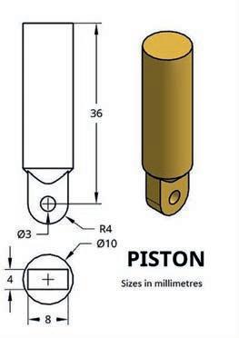
The next part is the piston If you’ve been able to create the previous parts, it will be easy ( 49 .
Step P1 – Create a Part Studio and make the sketch of 5 on the Top plane Use the Trim tool to remove all segments not needed from the rectangle construction
Step P2 – Extrude-New 32mm to create the cylindrical shape of the piston
Step P3 - Extrude-Add 8mm of the sketch rectangle in the opposite direction to the previous step
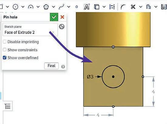
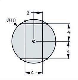
Step P4 – Create a sketch for the crankpin hole – 5
Step P5 – Extrude-Remove to create the crankpin hole The Hole tool could be used instead
Step P6 – Use the Fillet tool to create the shape in 52
Step P7 – Use the Chamfer tool as indicated in 53
Step P8 - Name your part, set the material and colour
Piston chamfer.
Spring.
Steps P6 and P7 are not essential to make our engine work in CAD but they improve the appearance
Spring

Now we go on to create the spring – 54 You will need to use tools not yet explained in this article. I recommend watching the video accessible via QR Code 8 or searching nshape pring’ on the Internet

The sketch process uses an auxiliary cylinder Around it, a helix is created Then you sketch the section of material (wire), usually a circle Finally, use the Sweep tool to generate the spring plaining step by step
Step S1 – Create a Part Studio and create a sketch on the Top plane with a 3 2mm diameter circle.

Step S2 - Extrude-New 10mm to build the au iliary cylinder
Step S3 – Use the Helix tool around the auxiliary cylinder face There are several parameters to defne the heli I chose the confguration of 55 www youtube com/watch?v= jNx9sOcBU8&t=89s

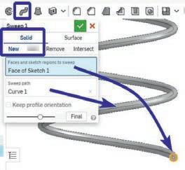
Step S5 – Use the Sweep command to create the spring – 57.
Step S6 - Name your part, set material and colour
In the Parts menu appears the auxiliary cylinder for the construction of the helix and a part named ‘Sections’, which corresponds to the spring
Step S4
– Create a sketch on the Front plane This plane will contain the starting point of the helix Draw a circumference of 0 2mm diameter – 56
Your last part, the spring, is created


