5 minute read
R a i l w a y B r a k i n g f o r M o d e l E n g i n e e r s
forked end lever at the wheel rim, fulcrum, spring balance and a series of weights (photo 6), taking care to eliminate any ‘stick-slip’ at the axleboxes by inching the locomotive backwards and forwards a few times.
* The next thing to do is to select the ‘brake percentage’ A value of 70 to 80% is normal for a locomotive or the loaded tender (where the driver sits upon it) but a suitable lower value, possibly up to 50% may be used for coaching stock where the load is variable
* The brake force is next calculated taking into account the total wheel loads and brake percentage.
* With this information, the brake lever ratio is selected by reference to the layout of the rigging in relation to the design of the locomotive or rolling
6 stock Where compensated rigging is employed, it is usual to set it up for equal brake force on each wheel It may entail some experimentation to achieve equal loads since ang ular displacements of the pull rods introduce errors.
* Before the brake cylinder diameter is calculated, it is necessary to decide on the effective working pressure of the system For a vacuum brake, 21 inches Hg is desirable providing a maximum pressure of 10 lb/in2 whilst for air brakes a working pressure of say 20 lb/in2 is safe and adequate
* Then calculate the brake cylinder diameter. The following worked example is included to assist in doing the maths: et us assume a acifc locomotive with only 6 of the 12 wheels braked
* So, if say the loco weighs 1,000 lb it is likely that the load on the braked wheels may be only 600 lb (establish by weighing
* The overall lever ratio works out at 6:1 he effciency of the brake linkage is assessed at 80%
* The maximum brake cylinder pressure is 10 lb/in2.
* The brake percentage is set at 70% o, we have
Brake Force = 0 7 x Wheel
Load
Brake Force = 0 7 x 600 = lb
Brake Force = Area of Piston x Pressure x Lever Ratio x ystem ffciency, so
Area of Piston = Brake Force / (Pressure x Lever Ratio x ystem ffciency
Area of Piston = 420 / (10 x 6 x 0.8)
Area of Piston = 8 75 in2 iameter of iston ( 3.33 in.
Use the nearest larger available piston seal diameter, in this example 3.375 in.
Stopping ist n
It is somewhat academic to calculate the stopping distance because you ‘have what you have!’ However, on straight and level track, a locomotive and train in 7¼ inc h gauge typically should be capable of stopping from 10 mph in about 60 feet The effects of gradients either up or down is, of course, very pronounced, especially with a fully laden train
It is possible to compute the approximate stopping distance and a reasonable estimate can be assumed using a uniform deceleration rate Once the total vehicle mass and brake force has been determined, the uniform deceleration rate can be calculated. From this, the stopping distance on lev el track can be predicted but it must be accepted that this is an approximation It is better to establish the braking distance by actual experiment

So, we start with: orce ass cceleration where Force f, is in lb (we model engineers like Imperial measurements )
Mass m (caution here - mass is in ‘slugs’, which is weight in lbs/32 2)
Acceleration a is in ft/sec2
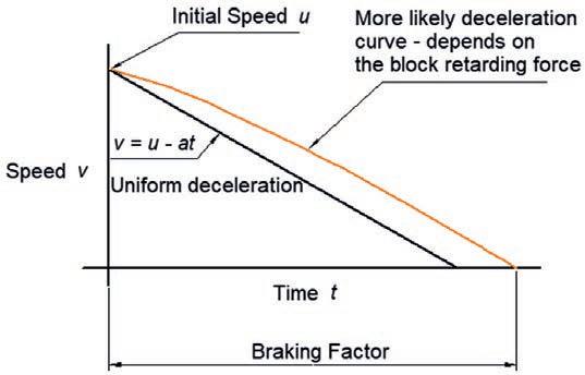
The graph in 7 illustrates two curves The black line is uniform deceleration and the coloured line, an estimate of the more likely rate of stopping.
From experience in 7¼ inch gauge, it seems practicable to design for higher deceleration rates since the initial speeds are low and friction is enhanced
As an example, the following is included to assist in doing the maths: ssuming the acifc locomotive example in the preceding section weighing , lb ass , slugs
Initial Speed (u) = 10 mph = . ft sec rake orce lb
Retarding orce rake orce lb raking actor f = m x a, thus a = - (84/1000) x 32 22 = -2 70 ft/sec2
We use one of the kinematics e uations to calculate the fnal speed (v): v2 – u2 = 2a x s, or s = (v² – u²) / 2a, so s = (0 - 14 72)/(2 x 2 70) = 40 feet pplying the raking actor
1 2 x 40 = 48 feet
In this approximation, the locomotive on its own would stop in approximately 48 feet Assuming its tender was similarly braked, a train might realistically stop on level track between 50 and 60 feet As previously outlined, the actual stopping distance is better determined by trial
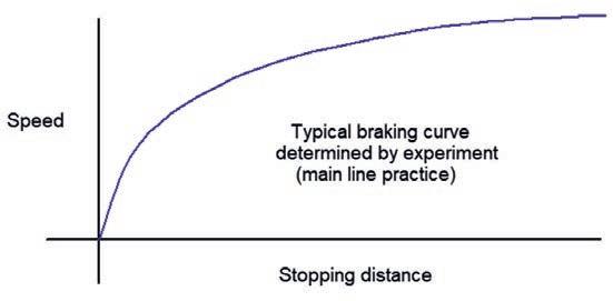
The braking curve shown in is typical of the work carried out by a brakes engineer for rolling stock on a main line railway. The average deceleration rate is usually measured in percentage of the acceleration due to gravity (%g) A typical service brake for a main line train would be approximately 9 %g and an enhanced (emergency) brake
12 %g (g = 32 2ft/sec2
Braking distance is also very dependent on rising and falling gradients The objective is frstly to carry out testing on uncontaminated rails to confrm that the normal braking performance falls within the mandated requirements A further test is carried out on ‘lubricated’ track to simulate winter climatic conditions and also to prove the wheel slide protection (WSP) devices work effectively Each vehicle of similar rolling stock should brake at the same rate Freight vehicles are usually ftted with variable load valves (VLVs) due to the large difference between tare (empty) and laden weights These valves are quite intricate and usually receive their control inputs from loads on the suspensions

Some DOs and DON’Ts!
eep it simple
* Do use rubber or soft seated valves
* Do use stiff brake beams and linkages
* Don’t use cable operated brake linkages
* Do use simple inter vehicle couplings
* Use compressed air and solvent to remove any swarf or debris from all pipe work before ftting leanliness is a virtue!
* Test every sub-system and every pipe joint before you assemble the fnal system. Then test the whole thing
* Ensure that brake hanger assemblies are hung accurately to ensure that blocks do not tend to ‘flange’ and that there is adequate lateral clearance to allow the blocks to follow the wheels on curves
* The blocks must be hung below the centre line of the wheel to ensure they fall away when released
* The action of the brake force should be through the wheel centre line.
* Since the mass of the brake pistons is small, the use of return springs is necessary to help release the brake
* Produce the very best of fts, flatness and surface fnish for brake valves
Deceleration assessment
An example of a brake test as carried out on a main line railway


