


















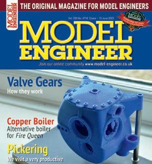
❖❖ VACUUM BRAKING How the vacuum is created and used Why I Write Geoff Theasby looks back The Elliptical Beam How the engine’s beam acquired its shape Boiler Making Construction step by step THE ORIGINAL MAGAZINE FOR MODEL ENGINEERS Vol. 231 No. 4719 16 –29 June 2023 Join our online community www.model-engineer.co.uk












Published by Mor tons Media Group Ltd, Media Centre, Morton Way, Horncastle, Lincs LN9 6JR Tel: 01507 529589 Fax: 01507 371066

© 2023 Mor tons Media ISSN 0026-7325


www model-engineer co uk


EDITORIAL
Editor: Mar tin R Evans
Deputy editor: Diane Carney
Designer: Druck Media Pvt Ltd
Club News: Geoff Theasby
Illustrator: Grahame Chambers
Publisher: Steve O’Hara
CUSTOMER SERVICES
General Queries and Back Issues
01507 529529
Monday-Friday: 8 30am-5pm
Answerphone 24hr
help@classicmagazines co uk
www classicmagazines co uk
ADVERTISING
Group adver tising manager: Sue Keily
Adver tising: Craig Amess

camess@mor tons co uk Tel: 01507 529537

Ad production: Andy Tompkins
By post: Model Engineer adver tising, Mor tons Media
Group, Media Centre, Mor ton Way, Horncastle, Lincs LN9 6JR
PUBLISHING
Sales and distribution manager: Carl Smith
Marketing manager: Charlotte Park
Commercial director: Nigel Hole
Publishing director: Dan Savage
SUBSCRIPTION
Full subscription rates (but see page 6 for offer): (12 months, 26 issues, inc post and packing) –
UK £128 70 Expor t rates are also available, UK subscriptions are zero-rated for the purposes of Value Added Tax


Enquiries: subscriptions@mor tons co uk

PRINT AND DISTRIBUTIONS
Printed by: William Gibbons & Son, 26 Planetary Road, Willenhall, West Midlands, WV13 3XB


Distribution by: Seymour Distribution Limited, 2 East Poultry Avenue, London EC1A 9PT
EDITORIAL CONTRIBUTION

Accepted photographs and articles will be paid for upon publication Items we cannot use will be returned if accompanied by a stamped addressed envelope and recorded delivery must clearly state so and enclose sufficient postage In common with practice on other periodicals, all material is sent or returned at the contributor’s own risk and neither Model Engineer, the editor, the staff nor Mortons Media Ltd can be held responsible for loss or damage, howsoever caused The opinions expressed in Model Engineer are not necessarily those of the editor or staff This periodical must not, without the written consent of the publishers first being given, be lent, sold, hired out or otherwise disposed of in a mutilated condition or in other unauthorised cover by way of trade or annexed to or as part of any publication or advertising, literary or pictorial manner whatsoever
Luis
34
Ron
38
Geoff
40
Doug
41

Bob
46


Jacques
SAVE UP TO 49% See page 6 for details

Luker presents a copper boiler for Fire Queen, as an alternative to stainless steel
John Arrowsmith discovers an extraordinarily diverse club on the Yorkshire moors
52 CLUB NEWS
Geoff Theasby compiles the latest from model engineering clubs around the world

http://www facebook com/modelengineersworkshop


http://twitter com/ modelengineers
Mike
O N T
H E C O V E R . . .
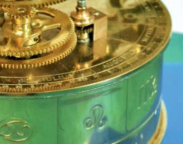
A solar system model simulating the motion of the ear th and moon around the sun by Ron Baier of the Pickering society
(photo: John Arrowsmith)
SMOKE RINGS
views and comment on the world of model engineering
THE EATING OF ELEPHANTS
Goodbody argues that anything is possible if you take it a bite at a time
BASIC OSCILLATOR STEAM ENGINE IN CAD
8
News,
9
Steve
12
Trincão leads us through the creation of a 3D
model of an oscillating steam engine
LNER B1 LOCOMOTIVE
CAD
14
Hewson presents a true to scale 5 inch gauge model of Thompson’s B1
RAILWAY BRAKING FOR MODEL ENGINEERS
18
Bramson explains the science and the practicalities of stopping trains
SLOTTING ON THE LATHE
22
Maurel investigates the forces involved in creating slots on a small lathe 26 RADIAL VALVE GEARS AGAIN Duncan Webster explores the subtleties of valve gear operation 29 INDEX TO VOLUME 230
BEER HEIGHTS LIGHT RAILWAY SIGNALLING
33
the
the
Heights
Vol. 231 No. 4719 16 – 29 June 2023
Hanscomb describes
signalling system at
Beer
Light Railway at Pecorama in Devon
THE STATIONARY STEAM ENGINE
Fitzgerald tells the story of the development of the stationary steam engine
WHY I WRITE (FOR MODEL ENGINEER)
Theasby explains himself
CLUB DIARY Future Events
A COPPER BOILER FOR FIRE QUEEN
WE VISIT PICKERING MODEL ENGINEERS
www.model-engineer.co.uk
This issue was published on June 16 2023 The next will be on sale on June 30, 2023 ❖❖ VA C U U M B R A K I N G How he vacuum s c eated and used Why I Write Geof Theasby ooks back The Ellipt cal Beam How the eng ne beam acqui ed ts shape Boiler Making Cons ruct on step by step THE OR G NAL MAGAZINE FOR MODEL ENG NEERS –Jo n o r on ne ommunity www mo e -e g nee co uk SUBSCRIBE
3 www.model-engineer.co.uk 14 46 22
&











Model Engineer 16 June 2023


www.model-engineer.co.uk









P R I N T O N LY Q u a r t e r l y d i r e c t d e b i t fo r £18.00 1 ye a r d i r e c t d e b i t fo r £65.00 1 ye a r c r e d i t / d e b i t c a r d fo r £70.00 P R I NT + D I G ITA L Q u a r t e r l y d i r e c t d e b i t fo r £21.00* 1 ye a r d i r e c t d e b i t fo r £82.99* 1 ye a r c r e d i t / d e b i t c a r d fo r £84.99* D I G I TA L O N LY 1 ye a r d i r e c t d e b i t fo r £49.00* 1 ye a r c r e d i t / d e b i t c a r d fo r £52.95* *Any digital subscription package includes access to the online archive Enjoy 12 months for just £65 GREAT REASONS TO SUBSCRIBE > Free UK deliver y to your door or instant download to your device > Great Savings on the shop price > Never miss an issue > Receive your issue before it goes on sale in the shop SUBSCRIBE AND SAVE L MAGAZINE FOR MODEL ENGINEERS V 9 N 70 4 - 1 m ou online community www m del-enginee c uk EDERATION AGM d Autumn Rally at Little Hay Midlands Show First impressions ❖❖ THE ORIGINAL MAGAZINE FOR M V 3 4 11 J n our n ne c mmu SCOT IMLEC 2023 We invite entries for this year s efficiency compeition We visit a bobb ❖❖ THE ORIGINAL MAGAZINE FOR MODEL ENGINEERS 4712Jo n ou on ne commun ty mode -eng nee Lincolnshire Line Exploring the history of the Lincolnshire Coast Light Railway h u r c h the 150th the s EC 2023 rd to the small ficiency competit on We V t Rye d a l e We tak p Nor th Yorksh re SAVE 49%
w w w.classicmagazines.co.uk /MEDPS 01507 529529 and quote MEDPS Lines open Monday to Friday 8 30am – 5 00pm GMT Offer ends December 31, 2023 Subscriptions will start with the next available issue Direct Debit payments will continue on the agreed plan unless you tell us otherwise To view the privacy policy for MMG Ltd (publisher of Model Engineer), please visit www mortons co uk/privacy Please visit www classicmagazines co uk/terms for full terms & conditions
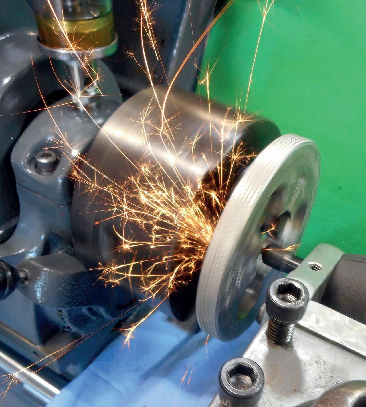
Jaw Regrinding - Pete Barker
Parklands Railway
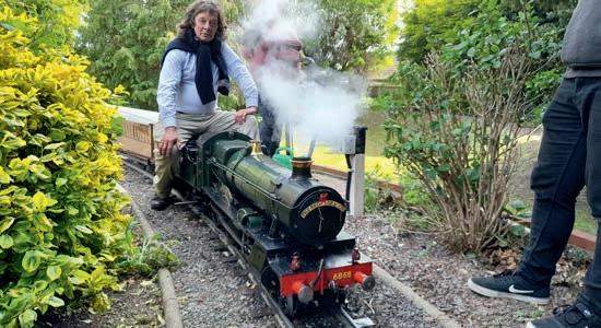
On Sunday May 28th I had the pleasure of attending the frst full running day of this year’s Parklands Railway Week, up at Hemsby on the Norfolk coast near Great Yarmouth. The Parklands railway is a 7¼ inch gauge railway in the grounds of a holiday park created by the late Don Witheridge and the railway week has now been an annual event (except during covid, sadly) for over 40 years There was a total of 23 engines present when I visited and most were staying
for the entire week I include here a couple of pictures of visiting locomotives to be going on with and we hope to include a more comprehensive report in a forthcoming issue
Summer Events
There are two events coming up in July which should be in the diary of anyone within reach of either Guildford or Oxford
In Guildford, on Saturday and Sunday the 1st and 2nd from 10am to 5pm at Stoke Park there is the Railway Gala, organised by the Guildford MES There is a ground level railway
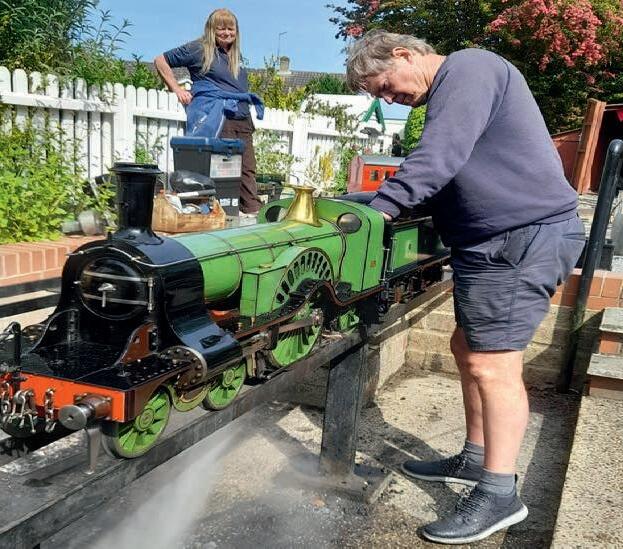
and a raised track, both offering rides, model traction engines, two model boating pools and a display of steam models Hot food is also available What’s more admission is free (except for the train rides – at modest fares) and so is parking. More details are at www gmes org uk/events htm
At Cutteslowe Park, Oxford from the 21st to the 23rd there is the ‘Dreaming Spires’ rally Home to the secondbest university in the country (ahem!), Oxford is also home to the club organising this event Road vehicles are welcome and railway locomotives of 3½, 5 or 7¼ inch gauges are invited to run on the ground level or raised tracks, provided of course they are equipped with a valid boiler cer tifcate (if relevant More information, if you plan to attend, is available from the club chairman, Denis Mulford (denis. mulford@btinternet.com).
Geoff Theasby

Many of you may have wondered why Geoff Theasby writes for this magazine (I know I have) but it is now no longer a mystery On page 38 Geoff spills the beans and reveals his motivations for putting pen to paper (apart from the accumulation of riches, of course s befts a model engineering magazine, it’s riveting stuff
Mar tin Evans can be contacted on the mobile number or email below and would be delighted to receive your contributions, in the form of items of correspondence, comment or ar ticles.


07710-192953
MEeditor@mor tons co uk


respectful distance

Model Engineer 16 June 2023
DIANE CARNEY Assistant Editor
MARTIN EVANS Editor
8
Stuart Duncan waits to leave the station sitting behind GWR 6868 Penrhos Grange The locomotive was built originally from works drawings by Tony Newbury and beautifully rebuilt by Stuart’s son James
Stoke Park Gala
Martin Parham blows down a very elegant Stirling Single, built from works drawings and exact in every detail, while Sue Parham observes from a
T h e E a t i n g o f E l e p h a n t s
Steve Goodbody

Having star ted to build Elidir, a 7¼ inch narrowgauge quarry Hunslet locomotive, and with A-level studies also underway, the author has discovered that the long daily journey to Brighton, coupled with more homework than he has ever seen in his life, are not conducive to steam engine construction Taking this into account, he has revised Elidir’s timing estimate upwards to eight years, cer tain in his belief that it could not possibly take longer
Perceptive readers might disagree with his conclusion
Progress, or lack thereof
‘Never judge a man until you’ve walked a mile in his moccasins’ Sound advice, if ever I heard it, and, in just twelve words (thirteen, if you count ‘you’ve’ as two words, which you shouldn’t) it neatly captures the idea that we all have constraints, and we all have limitations, and we are none of us the same as each other, and therefore we must all be wary of jumping to conclusions and casting aspersions because, chances are, we don’t know all of the relevant facts
And, having deployed that defensive smokescreen, I can
now admit that, having more limitations and constraints and differences than most, and thanks in large part to those annoyingly insistent educational demands which now ruled my life, and while I did manage to get Elidir up onto her wheels over the course of that nine-month period (photo 92 and photo 93), no further advancement was made during the school year In short, by July of 1986, progress had been, not to put too fne a point on it, unimpressive
However, like the proverbial bad penny, the school summer holiday eventually rolled around once again and this time I was ready For now, in the workshop, in an almost-tooheavy-to-lift cardboard box, and having once again consumed nearly all of my saved pocket money, sat the entire set of cylinder castings for a certain narrow-gauge Hunslet locomotive And, come hell or high water, I intended to get those castings machined and installed before the summer holidays were over
Hefty lumps
Now you, dear Reader, may recollect from the last episode that, before fully committing
to this latest project, I had spent time planning how I would go about machining those cylinders, for they were the largest and heaviest components of the engine by far And, if you cast your mind back even further, you may also recall that, while my workshop contained a capable lathe with many useful accessories, at roughly the same size as a Myford ML7 it was certainly not a large lathe and, having been built in 1905 or thereabouts, it was, to put it mildly, old And, furthermore, you will no doubt realize that, having no milling machine, if something couldn’t be machined on the lathe, or drilled on the benchtop drill press, then it had to be sawn, chiselled and fled by hand

In summary, and taken as a whole, these were the moccasins in which I was walking
Dusting off my notes from the planning session of the previous year, and with the castings now in hand for ultimate confrmation, I began to re-check each step of the machining sequence to ensure I had not dropped any clangers, and to confrm that the castings would actually ft on the lathe as intended, and to check that

9 www.model-engineer.co.uk >>
L
P A R T 16 – S T E P S B I G A N D S M A L
Continued from p 736
M E 4718 June 2
fnds some things are best tackled in small helpings
By the beginning of the 1986 summer holidays, Elidir was up on her wheels
One of the leaf springs, fnished and mounted in its buckle
92 93
they could be mounted and securely held as envisaged And, fortunately, with a few minor tweaks to accommodate the heavier-than-expected lumps of iron, the original plans appeared sound
And so, with a rough sketch as a guide, I made an adjustable fly-cutter, wiped as much oil from the lathe as I dared to prevent the cast iron dust from sticking, hefted the frst cylinder casting onto various packing-pieces attached to the lathe saddle, bolted it in place, put the lathe into its slowest back-gear speed and gingerly took the frst cut (photo 94)
Before too long, with the drain-cock bosses and the lower edge of the flanges machined flat and ready to act as the mounting surfaces for
the second operation, each cylinder was ready for the next setup And so, with the packing reconfgured and the frst casting re-mounted and clamped securely through the bore, the long task of machining the rest of each casting could begin in earnest - photo 95 and photo 96 hopefully provide an idea of the scale of the job relative to the size of the lathe. And, while some of the packing and bolting arrangements may look precarious to those readers more familiar with substantial milling machine tables and large vices, I can assure you, nervous Reader, that nothing was left to chance, each setup was solid and secure, and the entire job was fnished without mishap In fact, to my surprise, it all went rather well!
Even better, with the squareness of each setup painstakingly established using a large and rigid faceplate mounted on the lathe spindle (photo 97), a method of which I’m particularly fond, as each machining step for each cylinder was completed and the results carefully checked with engineer’s square, vernier calipers and height gauge as appropriate, to my admitted amazement I could fnd neither out-of-squareness nor signifcant inaccuracy as the work progressed
And so, with the port faces and mounting flanges fnished and square, and the crossheadend of the frst cylinder block faced to length with the fly cutter, I mounted a catch plate to the lathe spindle, inserted


my largest between-centres boring bar through the cylinder itself, attached a drive-dog to the bar, and prepared to machine the bore in the timehonoured way And about halfway through the frst cut, the sound emerging from the hole suddenly changed from the pleasant snick-snick-snick of a nice sharp tool happily cutting is way through grey cast iron to the ominous mrrring-mrrringmrrring of a dull tool which has had enough for the day Winding the cylinder away from the cutter I stopped the lathe and surveyed the situation
Sure enough, even a cursory glance showed that the high-speed-steel tool in the boring bar, while originally keenly ground to a knife-edge, was now rounded and blunt
10 Model Engineer 16 June 2023
Machining begins on the frst of Elidir’s cast iron cylinders
The author’s elderly George Adams lathe sits in his Crowborough workshop, an Elidir cylinder casting bolted on top.
The adjustable fycutter machines the large iron castings
A sturdy faceplate establishes and confrms squareness at each step of the process
94 95 96 97
Slackening the grub screw I removed the tool, returned it to sharpness with the bench grinder, and replaced it for another attempt Restarting the lathe, I wound the cylinder back along the tool and continued the cut, but, after no more than twenty seconds of this, that ominous mrrring sound began to emerge from the hole as before Puzzled, I inspected the recently sharpened tool once again, and saw, to my dismay, that it was already completely blun t Now what on earth was going on? Removing the boring bar from the cylinder I shone a light down the hole and, peering inside as best I could, noticed that there, right at the point where the cut had been twice abandoned, patches of the newly machined cast iron, rather than having the uniformly matt grey appearance that I expected, glittered brightly as if polished Now that’s strange, I thought, and departed the shed to do some research
Chilling out
Now Bob, my good friend and mentor, had recently retired from model engineering and divested his well-equipped workshop and, while I could not afford to buy more than a handful of small items from his collection, he had very kindly presented me with several excellent reference books as a gift And one of those books, or at least a few of them because they were a three-volume set, was the frst edition of Engineering Workshop Practice, an elegantly bound compendium published in 1936 by Caxton, together with a booklet of eleven coupons entitling the owner to receive ‘ free advice from the Engineering Workshop Practice Information Bureau in reply to one enquiry ’ And, while he doubted that the offer of free advice was still available given the ffty years since the book’s publication, Bob felt that I would make good use of the volumes regardless And, having read them from cover to cover by
the time I came to machine Elidir’s cylinders, I knew he was correct
And so, searching the index, I found what I was looking for on page 24 of Volume III under the unambiguous heading: ‘Cutting Chilled Cast Iron’ . And there, to quote directly from the book, it informed me that ‘ chilled cast iron is generally a very difficult material to machine, as the ‘skin’ is frequently harder than tool steel’ , a fact which I’d already discovered on my own Fortunately however, it went on to advise that it was possible to machine this pesky material with tungsten-carbide tools and that is what I wanted to know
Unfortunately, while I now knew how to solve the problem, I did not have any such tools in my arsenal and so, after removing as much of the pervasive iron dust from hands and arms and face as I could, and with a quick phone call to check that Barry had some in stock, I extracted my bike from the garage and began the long pedal to Rotherfeld, the new location of TBSITW, in search of a suitable carbide-tipped lathe tool to complete the job
And the next morning, having purchased two similar tools just in case, and a green grit grinding wheel to sharpen them when needed, and after making the necessary modifcations so that one of the tools would ft into the boring bar, I returned to the lathe and, with bated breath, began where I had left off
And my goodness, what a difference that tool made! In no time at all, or so it seemed, the frst cylinder’s bore was to size and, after replacing it with a back-cutting tool to machine the opposite end of the casting squarely to length, that cylinder was removed, its identical twin mounted in its place, and the job repeated once again. And a week or so later, with the ports and passages cut and the flanges and webs laboriously fled to shape, I pronounced both cylinder castings largely complete
A successful summer
By the end of that summer, the cylinder blocks, together
with their steam chests, valves, covers, glands and whatever else I have forgotten, were all fnished and mounted proudly on the chassis which, in protest at all the front-end weight, had, like Robin’s tram, adopted a decidedly nose-down attitude.
Of course, having spent the best part of six weeks reducing the castings to their fnal dimensions, and with plenty of time for my mind to wander in the meantime, a few more ‘What if?’ moments had occurred along the way
As a result, each steam chest now sported an additional tapped hole at its lowest point in readiness for an extra drain cock which, I reasoned, would be a worthwhile addition to help warm the cylinders at the start of each run and prevent rust by allowing condensate to be drained from the otherwise sealed iron box at the conclusion After all, if I was going to make four drain cocks I might as well make six, and if I was to make one set of linkages back to the cab then I might as well make two
Furthermore, and in a more radical departure from the design, I had decided to rotate each valve chest cover through 180 degree s from the drawings, thereby repositioning each cylinder’s steam-pipe connection behind the blastpipe rather than in front This, I believed would provide more flexibility at these flanged joints and reduce the chance of leaks when everything expanded and contracted with the heat, something I saw as a potential flaw in the as-drawn design
But further implementation of these aspirational plans would have to wait because, sadly, the summer holidays were once again over, my fnal year of A-level studies was about to begin, and I knew beyond doubt that I would have little time for model engineering in the meantime And so, having removed as much of the lingering cast iron dust as I possibly could, and after giving the workshop’s contents, including the now-
much-heavier Elidir chassis, a good coating of oil to help keep rust at bay, I turned off the lights, locked the door and set my alarm clock for ten-to-fve in readiness for a rude awakening the next morning
Postscript to Par t 16
The well-known quotation at the start of this episode, although it’s actually a misquote but let’s not be too picky, comes from the poem Judge Softly by Mary Torrans Lathrap, a Michigan-born ‘ poet, preacher, suffragist and temperance reformer’ (according to Wikipedia) and an absolute riot at parties (according to me, but I made that bit up).
Anyway, on a seemingly unrelated topic, several years ago my daughter graduated from middle school and departed to begin her high school education and, in line with the tradition in these parts, during that fnal middle-school year, her school produced a yearbook, a hardbacked tome flled with pictures and memories and anecdotes from each member of the graduating class, which was presented to each student at the graduation ceremony.
And flicking through that book one day, I came across a page devoted to quotations, each graduating student having contributed their favourite, and my eye was drawn to the choice of Thomas, a boy I knew well and a budding engineer to boot, who had selected the self-same paraphrased words from Judge Softly with which I began this episode
However, Thomas, to my even greater delight, went one better and added his own addendum to the traditional text, and I leave you with his version which still makes me laugh each time I read it:
‘Never judge a man until you’ve walked a mile in his moccasins
Because then you’re a mile away from him
And you have his moccasins ’
Thank you, Thomas
11 E L E P H A N T S www.model-engineer.co.uk
be continued
To
B a s i c O s c i l l a t o r S t e a m E n g i n e i n CA D
Luis Trincão takes us through the CAD process step by step.
Continued from p 747
M E 4718 June 2
Piston

The next part is the piston If you’ve been able to create the previous parts, it will be easy ( 49 .
Step P1 – Create a Part Studio and make the sketch of 5 on the Top plane Use the Trim tool to remove all segments not needed from the rectangle construction
Step P2 – Extrude-New 32mm to create the cylindrical shape of the piston
Step P3 - Extrude-Add 8mm of the sketch rectangle in the opposite direction to the previous step
Step P4 – Create a sketch for the crankpin hole – 5

Step P5 – Extrude-Remove to create the crankpin hole The Hole tool could be used instead


Step P6 – Use the Fillet tool to create the shape in 52
Step P7 – Use the Chamfer tool as indicated in 53
Step P8 - Name your part, set the material and colour

12 Model Engineer 16 June 2023
P A R T 4
Piston drawing
Fig 49
Piston sketch
Fig 50
Piston hole
Fig 51
iston fllet
Fig 52
Piston chamfer.
Spring.
Steps P6 and P7 are not essential to make our engine work in CAD but they improve the appearance
Spring

Now we go on to create the spring – 54 You will need to use tools not yet explained in this article. I recommend watching the video accessible via QR Code 8 or searching nshape pring’ on the Internet


The sketch process uses an auxiliary cylinder Around it, a helix is created Then you sketch the section of material (wire), usually a circle Finally, use the Sweep tool to generate the spring plaining step by step

Step S1 – Create a Part Studio and create a sketch on the Top plane with a 3 2mm diameter circle.

Step S2 - Extrude-New 10mm to build the au iliary cylinder
Step S3 – Use the Helix tool around the auxiliary cylinder face There are several parameters to defne the heli I chose the confguration of 55

www youtube com/watch?v= jNx9sOcBU8&t=89s
Step S5 – Use the Sweep command to create the spring – 57.
Step S6 - Name your part, set material and colour
In the Parts menu appears the auxiliary cylinder for the construction of the helix and a part named ‘Sections’, which corresponds to the spring
Step S4
– Create a sketch on the Front plane This plane will contain the starting point of the helix Draw a circumference of 0 2mm diameter – 56
Your last part, the spring, is created
13 C A D o o
Helix section
Helix tool
Fig 53
Fig 55
Fig 54
Fig 56
To be continued Sweep
Fig 57
L N E R B 1 L o c o m o t i v e
Doug Hewson presents an authentic 5 inch gauge version of Thompson’s B1 locomotive

Continued from p 739,
Ithought that this was a nice photo of a B1 61240 Harry Hinchcliffe photographed at Saltburn in Nor th Yorkshire in 1955 (photo 143) I had put this photograph to one side as it shows the front bogie to advantage It is the third type of bogie ftted to the s, as shown earlier in the series. It has the generator on the righthand foot plate and both Dave Noble and Mike Jack make a lovely casting for these

This time I want to describe how I made the valve liners and other bits and pieces to go with them ( 74 to 77)
irst of all, you need a good 1½ inch stick of Mehanite cast iron bar This needs turning down to inches diameter
and then turn down a inch length to about a thou under 1 1/16 as that should just give you enough room to Loctite
them in owever, before you do, I always like to turn a inch groove inches from the end where you push the liner in
9 holes no 43 on 1 3/16” PCD for 8BA studs
14 Model Engineer 16 June 2023
P A R T 22 – V A LV E L
I N E R S
M E 4718, June 2
Gratuitous photo of yet another B1
Front steam chest cover
143 Use cover as template for drilling liner 1 / 1 6 Ø 5 / 1 6 Ø 7 / 8 1 / 1 6 Drill Ø5/32 5/8 Tap 7BA 3/32 1/4
Fig 74
Die Blocks
15 L N E R B 1 o o >> Rear steam chest cover Valve liner 1 3 / 8 1 / 1 6 Ø 1 3 / 8 Ø 1 1 / 1 6 Ø 7 / 8 b o r e 3/16 1/8 2 1/8 1 1/8
1/4 when assembled Shallow groove to act as filing guide
ts filed diagonally to prevent rings from snagging & to give clean cut off 13/16 3/16 3/16 Slot to suit 1/4 3 / 1 6 5 / 1 6 3 / 8 3 / 8 1 / 4 5 / 1 6 7 / 1 6 5 / 1 6 7 / 1 6 1 / 2 9 / 3 2 1 / 4 1 / 4 1 1 / 3 2 1 / 2 Ream Ø5/32 Ø1 3/16 1 1/4 1/16 Centreline of combination lever Silver steel pin 21/32” long Centreline of steam chest cover 1/2 1/2 Brass spacer either side 3/4 3/4 7/8 7/8 9/16 1/4 1/4 3/16
3
Por
Rear Steam Chest Cover Mat’l: Gunmetal casting 3/4 Tap 5BA 1/8 Slight angle 3/16 3/32 1 21/32 Drain cock operating rod Drill 9 holes no 43 for 8BA bolts Frame plate Tap 10BA 3/8 3/32 1 29/32 1/4 Valve slides For lubricator connections
Fig 76 Fig 75
from his will give you a fling groove to shape the steam inlet vents a lozenge shape This is not only because that is how the full size ones are but also to hopefully to prevent any snagging of the rings on the port edges The flanges also need drilling with nine No holes at pitch circle diameter


Now back to those lozenge shaped slots hoto ph 44 shows me cutting the groove around the valve liner so that I could use it as a guide for fling the drillings into those lozenge shaped holes Note also the slot for the exhaust towards the end of the liner The liner was f ed in with a good pasting

of Loctite and the two halves had to be carefully aligned with the e haust port lso, the inlet ports in the liners need to be matching the cylinder block so that everything lines up hoto ph 45 shows me drilling the holes with my little template I used for aligning the eight holes for drilling hoto ph 46 is my method of fling the ports to that lozenge shape which I keep going on about I don’t know whether this makes any difference to the actual performance but that is how they are on the full-size engine so that is how they had to be on my own engine!
Now if you have a look at my drawing of the front steam chest cover (fg you will see there is a small tapping which is for an oiling point for the valve tail rod This has a pipe from the rear of the oil box just in front of the steam pipe entrance to the cylinder There are two pipe clips for this pipe which slope up gradually to this swab box hoto ph 47 shows this oiling point and photo 4 shows the continuation of the oil pipe hoto ph 49 shows the drain cock rod passing through the rear steam chest cover so this is another thing which needs very careful alignment but as a guide you can use one of the holes to f the cover as the hole at the rear stud is dead in line across the centre, but that is the only one
The rear steam chest cover should ideally be a lost wax casting owever, if anyone feels the need to make their own you can - just add 4% to all the dimensions and it will be done The only thing is that you will need to also make another one opposite hand! This is much easier if you have access to a printer, or if one of your mates has access to one You need to ask advice on this about the shrinkage Whoever makes the pattern also needs to make the patterns for the left and right-hand valve guides It would make life much easier!
Essentially the rear covers are circular in section with various holes cut out of them!
16 Model Engineer 16 June 2023
Machining a groove for the lozenge shaped holes
Ø 7 / 8 7 / 8 Ø 5 / 8 Ø 1 / 4 Ø 5 / 3 2 Ø 1 1 / 3 2 Ø 9 / 3 2 3 / 1 6 1 / 2 7 / 1 6 5 / 3 2 5 / 1 6 Ø3/16
Drilling holes to position the lozenge shapes
Ø1/16 oil pipe soldered through crosshead
Bobbin Carrier Mat’l: Brass or stainless
Valve Crossheads Mat’l: Brass fabrication
20° Ream
1/16
0 328 3/32 1/16 4 1/2 4 1/16 3/4 Silver solder 1 2 595 7 7/16 3 1/4 1/2 9/16 1/4 3/4 1/4 x 40
Valve Spindle Mat l: Stainless steel
Ø1/4
grooves for cast iron rings or alternatively oil grooves Bobbins could be made in 3 pieces to facilitate fitting rings
77 Valve spindle 144 145 Filing out the lozenges 146
Fig
ow, for some time I have been in conversation or by email with Eddie Gibbons on Tyneside who has been commissioning my , so
before I get into making the piston valves, I will present the drawing as I had originally drawn it Eddie is much in favour of ftting proper rings on
his engines, so he has made new piston valves with four rings on each bobbin for my e has now removed thou from the outer ends of both bobbins which has given the engine just a little bit of lead and now says that it has given the engine its ‘chuff’ back hoto ph 5 shows my new valves and that was another transformation to my engine.
The valve spindles are really just a plain turning job but if you do want to make the engine chuff a bit then you will need to reduce the length of each bobbin by thou he spindle is held into the yoke at the rear end and is held in by a vertical key You will also need to ft a taper pin at an angle of 20 degrees to hold the pin in place I made the die blocks as


two sets of four but I am afraid that the only photograph of that which I have (photo 5 ) is rather blurred so I just hope that the powers that be might have a better way of making them a bit better so that at least you can get the message! I have also shown 1 inch of flat on the tail end of the spindle so that you do not get any compression in the tail rod gland otherwise it might blow bubbles in the oil box
To be continued
NEXT TIME
We make the cylinder covers and drain cocks


L N E R B 1 o o
Valve tail rod oiling point
Valve tail rod oiling point
A stick of die blocks.
Path of the oil pipe.
Drain cock linkage
147 148
149
150
151
M E 4718 June 2
How to go about designing a brake inst tion tions
All engineering is a combination of the theoretical and the practical. It is senseless just to pitch-in and make things without frst planning what has to be achieved and how to do it
The steps in designing a brake installation are straight forward and involve the following:
* Firstly – establish each individual wheel load, by estimation, calculation or actual weighing It is worthwhile to actually weigh the wheels using a simple

P
A R
R a i l w a y B r a k i n g f o r M o d e l E n g i n e e r s
forked end lever at the wheel rim, fulcrum, spring balance and a series of weights (photo 6), taking care to eliminate any ‘stick-slip’ at the axleboxes by inching the locomotive backwards and forwards a few times.
* The next thing to do is to select the ‘brake percentage’ A value of 70 to 80% is normal for a locomotive or the loaded tender (where the driver sits upon it) but a suitable lower value, possibly up to 50% may be used for coaching stock where the load is variable
* The brake force is next calculated taking into account the total wheel loads and brake percentage.

* With this information, the brake lever ratio is selected by reference to the layout of the rigging in relation to the design of the locomotive or rolling
6
stock Where compensated rigging is employed, it is usual to set it up for equal brake force on each wheel It may entail some experimentation to achieve equal loads since ang ular displacements of the pull rods introduce errors.
* Before the brake cylinder diameter is calculated, it is necessary to decide on the effective working pressure of the system For a vacuum brake, 21 inches Hg is desirable providing a maximum pressure of 10 lb/in2 whilst for air brakes a working pressure of say 20 lb/in2 is safe and adequate
* Then calculate the brake cylinder diameter. The following worked example is included to assist in doing the maths:
et us assume a acifc locomotive with only 6 of the 12 wheels braked
* So, if say the loco weighs 1,000 lb it is likely that

18 Model Engineer 16 June 2023
Bob Bramson explains the important business of bringing trains to a halt in a controlled manner T 3
Continued from p 771
‘Weighing’ the wheel loads of a large 7¼ inch gauge locomotive
the load on the braked wheels may be only 600 lb (establish by weighing
* The overall lever ratio works out at 6:1
* The maximum brake cylinder pressure is 10 lb/in2.
he effciency of the brake linkage is assessed at 80%
* The brake percentage is set at 70% o, we have
Brake Force = 0 7 x Wheel
Load
Brake Force = 0 7 x 600 = lb
Brake Force = Area of Piston x Pressure x Lever Ratio x ystem ffciency, so
Area of Piston = Brake Force / (Pressure x Lever Ratio x ystem ffciency
Area of Piston = 420 / (10 x 6 x 0.8)
Area of Piston = 8 75 in2 iameter of iston ( 3.33 in.
Use the nearest larger available piston seal diameter, in this example 3.375 in.
Stopping ist n
It is somewhat academic to calculate the stopping distance because you ‘have what you have!’ However, on straight and level track, a locomotive and train in 7¼ inc h gauge typically should be capable of stopping from 10 mph in about 60 feet The effects of gradients either up or down is, of course, very pronounced, especially with a fully laden train
It is possible to compute the approximate stopping distance and a reasonable estimate can be assumed using a uniform deceleration rate Once the total vehicle mass and brake force has been determined, the uniform deceleration rate can be calculated. From this, the stopping distance on lev el track can be predicted but it must be accepted that this is an approximation It is better to establish the braking distance by actual experiment

So, we start with:
orce ass cceleration
where Force f, is in lb (we model engineers like Imperial measurements )
Mass m (caution here - mass
is in ‘slugs’, which is weight in lbs/32 2)
Acceleration a is in ft/sec2
The graph in 7 illustrates two curves The black line is uniform deceleration and the coloured line, an estimate of the more likely rate of stopping.
From experience in 7¼ inch gauge, it seems practicable to design for higher deceleration rates since the initial speeds are low and friction is enhanced
As an example, the following is included to assist in doing the maths:
ssuming the acifc locomotive example in the preceding section weighing , lb
ass , slugs
Initial Speed (u) = 10 mph = . ft sec rake orce lb
Retarding orce rake orce lb
raking actor
f = m x a, thus a = - (84/1000)
x 32 22 = -2 70 ft/sec2
We use one of the kinematics e uations to calculate the fnal speed (v):
v2 – u2 = 2a x s, or
s = (v² – u²) / 2a, so
s = (0 - 14 72)/(2 x 2 70) = 40 feet
pplying the raking actor
1 2 x 40 = 48 feet
In this approximation, the locomotive on its own would stop in approximately 48 feet Assuming its tender was similarly braked, a train might realistically stop on level track between 50 and 60 feet As previously outlined, the actual stopping distance is better determined by trial
The braking curve shown in is typical of the work carried out by a brakes engineer for rolling stock on a main line railway. The average deceleration rate is usually measured in percentage of the acceleration due to gravity (%g) A typical service brake for a main line train would be approximately 9 %g and an enhanced (emergency) brake
12 %g (g = 32 2ft/sec2
Braking distance is also very dependent on rising and falling gradients The objective is frstly to carry out testing

on uncontaminated rails to confrm that the normal braking performance falls within the mandated requirements A further test is carried out on ‘lubricated’ track to simulate winter climatic conditions and also to prove the wheel slide protection (WSP) devices work effectively Each vehicle of similar rolling stock should brake at the same rate Freight vehicles are usually ftted with variable load valves (VLVs) due to the large difference between tare (empty) and laden weights These valves are quite intricate and usually receive their control inputs from loads on the suspensions
Some DOs and DON’Ts!
eep it simple
* Do use rubber or soft seated valves
* Do use stiff brake beams and linkages
* Don’t use cable operated brake linkages
* Do use simple inter vehicle couplings
* Use compressed air and solvent to remove any swarf or debris from all pipe work before ftting leanliness is a virtue!
* Test every sub-system and every pipe joint before you assemble the fnal system. Then test the whole thing
* Ensure that brake hanger assemblies are hung accurately to ensure that blocks do not tend to ‘flange’ and that there is adequate lateral clearance to allow the blocks to follow the wheels on curves
* The blocks must be hung below the centre line of the wheel to ensure they fall away when released
* The action of the brake force should be through the wheel centre line.
* Since the mass of the brake pistons is small, the use of return springs is necessary to help release the brake
* Produce the very best of fts, flatness and surface fnish for brake valves
Deceleration assessment
An example of a brake test as carried out on a main line railway
19 B R A K I N G www.model-engineer.co.uk >>
Fig 17
Fig 18
* Make provision for adjustment for wear and after wheel re-profling
* Always check the system effectively and carry out a brake continuity test before setting off with a train.
* Maintain the system in perfect working order at all times
* Don’t forget to drain condensate out of the system after every run
Using the vacuum brake –pr s r i s
The system must be checked for mechanical and system integrity Ensure that the engine is set on level track and cannot roll away If any of the preservice checks fails to meet requirements, the cause must be established and remedied before the locomotive is passed ft for service
Visually examine the brake linkage for any signs of damage and ensure that all cotters and split pins are in place and suitably secured
Release the hand brake and ensure that the brake blocks fall away from the wheels and that block clearances are not excessive
Secure the tender vacuum hose on its dolly and ensure that the engine to tender flexible vacuum pipe is connected, that the driver’s brake valve (DBV) handle is in the ‘OFF’ position and the ejector steam valve on the DBV is shut
The brake tests may be undertaken with at least 50 lb/ in2 steam pressure available I nsure that any by-standers are clear of the chimney exhaust as hot water condensate will be expelled upon frst opening the ejector steam valve. Open the ejector isolating valve on the turret and then ‘blow up’ the vacuum by opening the ejector steam valve on the DBV When the system is fully exhausted, the train pipe vacuum gauge should register 21 inches Hg Ensure that the brake blocks are not applied to the wheels
With the gauge registering 21 inches Hg shut off the ejector ote the time taken for
the train pipe vacuum to fall to 15 inches Hg This should be greater than 30 seconds
Open the ejector and restore the vacuum (during the initial commissioning tests, the s tand-up time should be in e cess of fve minutes . Make a full brake application and shut off the ejector ote the time taken for the brake blocks to release This should be greater than two minutes (during the initial commissioning tests, the stand-up time should be maintainable for around an hour) Return the brake handle to the ‘OFF’ position and restore the vacuum by opening the ejector steam valve Before coupling to the train, destroy the train pipe vacuum. Then, couple and ‘blow up’ the whole train When the train pipe registers 21 inches Hg the guard must apply the brake at the rearmost position of the train (Standard Brake Test) and the driver should observe that the train pipe vacuum falls to between 0 and 3 inches Hg The train should be checked to ensure that all blocks are frmly applied to the wheels he guard closes the rear cock or replaces the vacuum hose on its dolly and the train pipe vacuum should re-set to 21 inches Hg. with the brakes released.
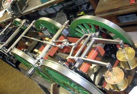
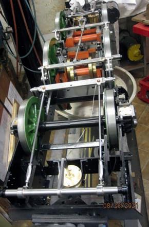
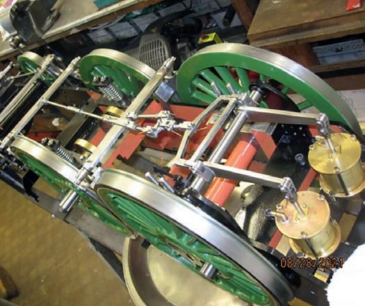
Photographs 7 and 8 show the brake system on one of the author’s locomotives ote that, for ease of maintenance,
the brake system for the driving wheels is non-prototypical
Using the vacuum brakeop
The art of braking a train will probably be learned over a period of time. The ‘feel’ of the brake is a tactile experience and takes a while to master The effectiveness of the brake depends upon many factors - perhaps the main variable is the friction conditions at the wheel to rail and wheel to brake interfaces All this is part of the ‘feel’ experience Allow plenty of distance for service braking and always try the brake soon after setting off to ensure that the system is operating effectively, especially when rail conditions are contaminated or wet.
I hen rail head conditions are degraded (frst train out or in adverse weather) make light brake applications at appropriate intervals to ‘prove’ the brake and to condition the wheel treads/blocks This is known as ‘defensive driving’ and is good practice
When in motion, the steam valve to the ejector must remain open at all times It will be found that there is an optimum position for the valve opening at different levels of boiler pressure For example, at low pressures (40 p s i ) the valve will be fully open At full pressure, the valve may be almost shut The ideal position
for the valve can be established and easily set by reference to the o’clock position of the handle This technique is the same in full size practice
To apply the brake, the drivers brake valve handle is moved towards the driver The power of the brake application directly relates to the degree of train pipe vacuum destroyed Do not ‘fan’ the brake handle (rock it backwards and forwards) - a steady reduction of vacuum is best obtained by a gradual application ote that on falling gradients, the braking distance will be greater than on level or up gradients
To release the brake, the drivers brake valve handle is moved away from the driver The release is not instantaneous as is the case with a motor car but takes a few seconds while the train pipe vacuum is re-created On level track or slight down grades, a light application, say to 16 inches Hg, should check the train speed A service application may be assumed at around 10 inches Hg An emergency brake application is when the drivers brake valve is set to ’ and the t rain pipe vacuum is dropped instantaneously to 0 inches Hg In this position, the ejector is by-passed and does not pull on the train pipe. Emergency braking should be avoided whenever possible to minimise damage (wheel flats) and
20 Model Engineer 16 June 2023
r ting t r
7 8
ra e system on the author s th scale Atlantic locomoti e


