4 minute read
L N E R B 1 L o c o m o t i v e
Doug Hewson presents an authentic 5 inch gauge version of Thompson’s B1 locomotive
Continued from p 739,
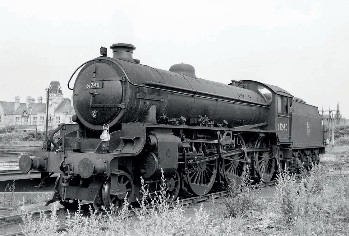
Ithought that this was a nice photo of a B1 61240 Harry Hinchcliffe photographed at Saltburn in Nor th Yorkshire in 1955 (photo 143) I had put this photograph to one side as it shows the front bogie to advantage It is the third type of bogie ftted to the s, as shown earlier in the series. It has the generator on the righthand foot plate and both Dave Noble and Mike Jack make a lovely casting for these
This time I want to describe how I made the valve liners and other bits and pieces to go with them ( 74 to 77) irst of all, you need a good 1½ inch stick of Mehanite cast iron bar This needs turning down to inches diameter and then turn down a inch length to about a thou under 1 1/16 as that should just give you enough room to Loctite them in owever, before you do, I always like to turn a inch groove inches from the end where you push the liner in
9 holes no 43 on 1 3/16” PCD for 8BA studs
Die Blocks
from his will give you a fling groove to shape the steam inlet vents a lozenge shape This is not only because that is how the full size ones are but also to hopefully to prevent any snagging of the rings on the port edges The flanges also need drilling with nine No holes at pitch circle diameter
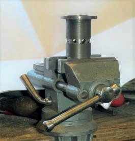
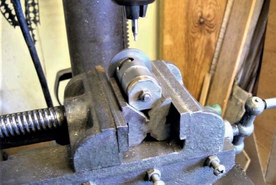
Now back to those lozenge shaped slots hoto ph 44 shows me cutting the groove around the valve liner so that I could use it as a guide for fling the drillings into those lozenge shaped holes Note also the slot for the exhaust towards the end of the liner The liner was f ed in with a good pasting of Loctite and the two halves had to be carefully aligned with the e haust port lso, the inlet ports in the liners need to be matching the cylinder block so that everything lines up hoto ph 45 shows me drilling the holes with my little template I used for aligning the eight holes for drilling hoto ph 46 is my method of fling the ports to that lozenge shape which I keep going on about I don’t know whether this makes any difference to the actual performance but that is how they are on the full-size engine so that is how they had to be on my own engine!
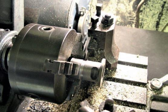
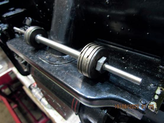
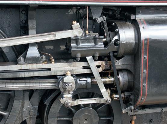
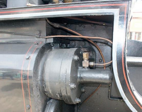
Now if you have a look at my drawing of the front steam chest cover (fg you will see there is a small tapping which is for an oiling point for the valve tail rod This has a pipe from the rear of the oil box just in front of the steam pipe entrance to the cylinder There are two pipe clips for this pipe which slope up gradually to this swab box hoto ph 47 shows this oiling point and photo 4 shows the continuation of the oil pipe hoto ph 49 shows the drain cock rod passing through the rear steam chest cover so this is another thing which needs very careful alignment but as a guide you can use one of the holes to f the cover as the hole at the rear stud is dead in line across the centre, but that is the only one ow, for some time I have been in conversation or by email with Eddie Gibbons on Tyneside who has been commissioning my , so before I get into making the piston valves, I will present the drawing as I had originally drawn it Eddie is much in favour of ftting proper rings on his engines, so he has made new piston valves with four rings on each bobbin for my e has now removed thou from the outer ends of both bobbins which has given the engine just a little bit of lead and now says that it has given the engine its ‘chuff’ back hoto ph 5 shows my new valves and that was another transformation to my engine.
The rear steam chest cover should ideally be a lost wax casting owever, if anyone feels the need to make their own you can - just add 4% to all the dimensions and it will be done The only thing is that you will need to also make another one opposite hand! This is much easier if you have access to a printer, or if one of your mates has access to one You need to ask advice on this about the shrinkage Whoever makes the pattern also needs to make the patterns for the left and right-hand valve guides It would make life much easier!
Essentially the rear covers are circular in section with various holes cut out of them!
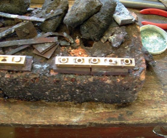
The valve spindles are really just a plain turning job but if you do want to make the engine chuff a bit then you will need to reduce the length of each bobbin by thou he spindle is held into the yoke at the rear end and is held in by a vertical key You will also need to ft a taper pin at an angle of 20 degrees to hold the pin in place I made the die blocks as two sets of four but I am afraid that the only photograph of that which I have (photo 5 ) is rather blurred so I just hope that the powers that be might have a better way of making them a bit better so that at least you can get the message! I have also shown 1 inch of flat on the tail end of the spindle so that you do not get any compression in the tail rod gland otherwise it might blow bubbles in the oil box
To be continued
Next Time
We make the cylinder covers and drain cocks
M E 4718 June 2
How to go about designing a brake inst tion tions
All engineering is a combination of the theoretical and the practical. It is senseless just to pitch-in and make things without frst planning what has to be achieved and how to do it
The steps in designing a brake installation are straight forward and involve the following:
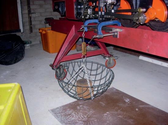
* Firstly – establish each individual wheel load, by estimation, calculation or actual weighing It is worthwhile to actually weigh the wheels using a simple
P
A R


