


This is part of our brand name library available at: www.HoseWarehouse.com/catalogs Warehouse HOSE Authorized Wholesale Distributor Bulk Pricing Trained Techs & Customer Supoort Quick Order Fulfillment Product Warranty Product Traceability Recall notification

3
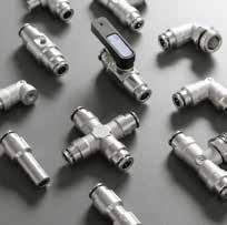
87-88 Series Push-to-ConnectFittings forInchTube
6
2
55-56 Series NylonPush-to-ConnectFittings forMetricTube
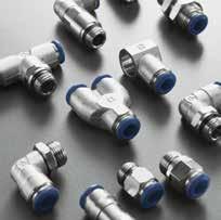
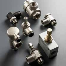
57 Series MetallicPush-to-ConnectFittings forMetricTube
5
85 Series NylonPush-to-ConnectFittings forInchTube
1
FunctionalFittings 9 Stainless
50N Series Push-to-ConnectFittings forMetricTube StainlessSteelPush-to-Connect FittingsandAdapters
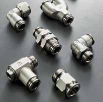
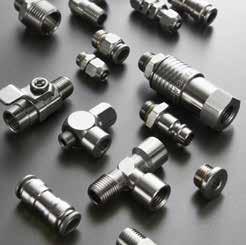
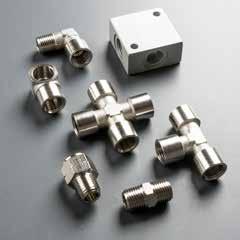
89 Series MetallicPush-to-ConnectFittings forInchTube 8
Functional Series 4
Series Index Mist Fit Series Push-InFittingsforMistingsSystems
7 Page 1
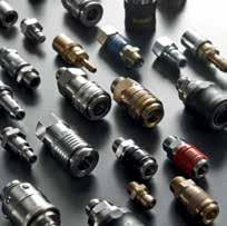
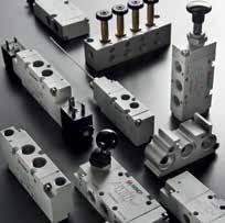
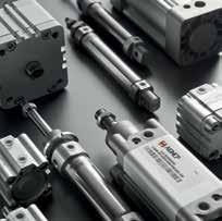
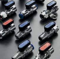
Actuators PneumaticActuators Valves Manual,Mechanical,AirPilot AndSolenoidPilotValves Quick-Disconnect Couplers QuickDisconnectCouplers www.aignep.com www.aignepusa.com Adapters NickelPlatedBrassAdapters Ball Valves ChromePlatedBrassBallValves Index Frl AirTreatmentUnit 12 11 10 15 14 13 Page 2
Aignep SPA
EXCELLENT SOLUTIONS IN FLUIDTECHNOLOGY


For over 40 years, Aignep is leading manufacturer of compressed air and industrial fluid fittings. Our company is driven by a constantly innovative spirit which has brought us to great results in various sectors of industrial automation. Our products are widely known for their high quality and Italian design: pneumatic cylinders and solenoid valves, fluid process control valves “FLUIDITY”, compressed air pipeline “INFINITY”, fittings and quick couplings for every fluid media. All the products are engineered by a dedicated professional team and manufactured in Italy in the production site of Bione, 22.000 m2.
More than 13.000 standard items in the catalogue and numerous special versions on demand. Every year Aignep invests in automation, innovation and services to satisfy the requests of a worldwide customer base.


Precisely to be closer to our customers our company has 5 regional branches: USA, Spain, France, Switzerland and Brasil, becoming a multinational Group.

“Move the Fluid Power!”
“Listening to our customers, understanding their needs is the power that drives us to develop everyday new solutions for fluid and compressed air”.
Page 3
Aignep USA

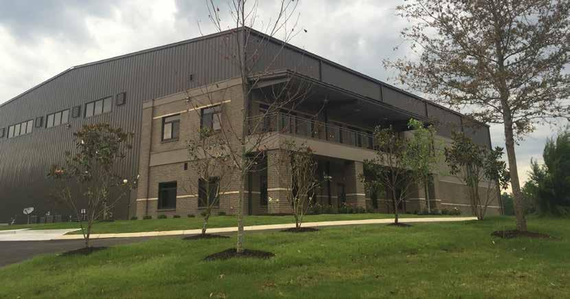
In the mid-1990’s, Aignep partnered with Alpha Technologies to expand into North America. The North American headquarters relocated in 2015 to a new, state-of-the-art facility in Fairview, TN. which also serves as a cylinder production site.


Over the past 20 years both Aignep and Alpha Technologies have experienced extensive growth and has resulted in the establishment of 7 locations throughout the world.


As Aignep’s global footprint continues to expand it was strategically important to change the name from Alpha Technologies to Aignep USA.

Page 4
GRAZIANO BUGATTI
T: +33 27 22 42 650
F: +33 27 22 42 651
AIGNEP (Wuxi) FLUID TECHNOLOGY CO., LT D. NO. 8, Yanggong Road, Nanhu Main Road, Wuxi Jiangsu.


T: +86 0510 8544 1923
F: +86 0510 8540 0223 aignep.cn@aignep.com
SPA Via Don G. Bazzoli - 34 25070 Bione (BS) ITALY
+39 0365 896626 F:
896561 aignep.it@aignep.com
USA LLC 7121 Loblolly Pine Blvd Fairview, TN 37062 U.S.A. T: +1 615 771 6650 F: +1 615 771 0926 aignep.usa@aignep.com
IBERICA SA Pol. Ind. el Tortuguer “Can Prat” Naves 23 y 24 08691 Monistrol de Montserrat - Barcelona SPAIN T: +34 93 828 47 36 F: +34 93 828 44 32 aignep.es@aignep.com
around the world AIGNEP
T:
+39 0365
AIGNEP
AIGNEP
FRANCE
AIGNEP FRANCE SARL 2, Avenue des Amèthystes 44338 Nantes Cedex 3
aignep.fr@aignep.com
CHINA
ALBANIA ALGERIA ARGENTINE AUSTRALIA AUSTRIA AZERBAIGIAN BELARUS BELGIUM BOLIVIA BOSNIA HERZEGO
VINA
BRASIL BULGARIA
CAMEROON
CANADA CHILE CHINA COLOMBIA COSTA RICA CROATIA CYPRUS CZECH
REPUBLIC DEM. REP. CONGO DENMARK ECUADOR EGYP T EIRE ESTONIA ETHIOPIA FINLAND FRANCE GERMA
Page 5
NY GHANA GREAT BRITAIN GREECE GUATEMALA HONG KONG HUNGARY ICELAND INDIA INDONESIA IRAN IRAQ ISR AEL ITALY IVORY COAST JAPAN JORDAN KAZ AKISTAN KUWAIT LATVIA LEBANON LITHUANIA LUXE
AIGNEP AG Industriestrasse 22A CH-2545 Selzach

SWITZERLAND
T: +41 32 342 09 09
F: +41 32 342 09 11
aignep.ch@aignep.com
Find
EDONIA
AIGNEP DO BRASIL COMERCIO DE COMPONENTES PARA AUTOMAÇÃO LTDA
Rua Batista Pereira, 99 - Macuco Vila Mathias - 11015-011 - Santos/SP
BRASIL
T: +55 13 2138 4049
F: +55 13 2138 4052
aignep.br@aignep.com
AIGNEP LATAM SAS
Sede:
Calle 15, N 27-78, Local 7 Sec. Paloquemao - 111411

Bogotá COLOMBIA
T: +57 1 37 52 50 1
T: +1 37 52 52 50 8
Sucursal:
Carrera 50 FF, N 8 Sur - 27 Ofi 404 Edificio 8908 - 050023

Medellin COLOMBIA
T: +57 46 04 25 34
T: +57 46 04 21 87
aignep.latam@aignep.com www.aignep.com.co
THAIL
your local distributor at: service@aignepusa.com
MBOURG MALAYSIA MAROCCO MEXICO MOLDOVA NEW ZELAND NICAR AGUA NIGERIA NORTH MAC
NORWAY OMAN PAKISTAN PERU PHILIPPINES POL AND PORTUGAL QATAR REPUBLIC OF DOMINICANA REPUBLIC OF MACEDONIA ROMANIA RUSSIA SAUDI ARABIA SENEGAL SERBIA SINGAPORE
SLOVAKIA SLOVENIA SOUTH AFRICA SOUTH KOREA SPAIN SWEDEN SWITZERLAND TAIWAN TANZ ANIA
Page 6
AND THE NE THERLANDS TUNISIA TURKE Y UKR AINE UAE URUGUAY USA VIETNAM YEMEN
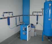
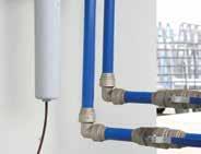
Infinity Series

Distribution system for compressed air, inert gases and vacuum
Request Catalogue
Page 7
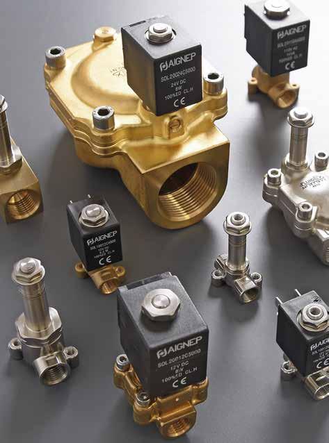
Fluidity Series

Fluid Solenoid valves


Request Catalogue
Page 8


PED Certifications DM174 / 2004 Page 9


Services Your documents online Your orders in one click Our catalogues at your disposal Catalogues Page 10
89 Series
Aignep reserves the right to vary models and dimensions without notice Aignep reserves the right to vary models and dimensions without notice


89000 Pg.1.5 89700 Pg.1.9 89030 Pg.1.7 89010 Pg.1.5 50980 Pg.1.9 89105 Pg.1.7 89110 Pg.1.5 50991 Pg.1.9 89040 Pg.1.7 89210 Pg.1.6 50006 Pg.1.9 89050 Pg.1.7 89222 Pg.1.6 89130 Pg.1.8 89000 Pg.1.5 89230 Pg.1.8 89210 Pg.1.6 89500 Pg.1.8 89110 Pg.1.5 89310 Pg.1.8 89222 Pg.1.6 88610B Pg.1.9 89055 Pg.1.7 Page 11
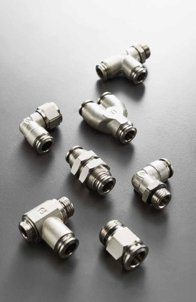
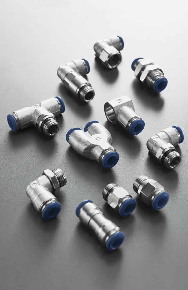
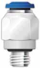
METALLIC PUSH-TO-CONNECT FITTINGS FOR INCH TUBE
89 Series
89000 Page 12
TECHNICAL CHARACTERISTICS
Bar
Pressure Rating
Vacuum ~ 290 PSI
-0.99 bar ~ 20 bar -0.099 MPa ~ 2.0 MPa
•
Media
Compressed Air
• Vacuum Water
• Steam (FKM required)
• Textile, Packaging
Compressed Air Circuit
• Vacuum
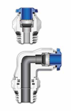
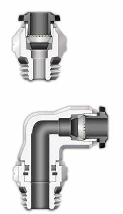
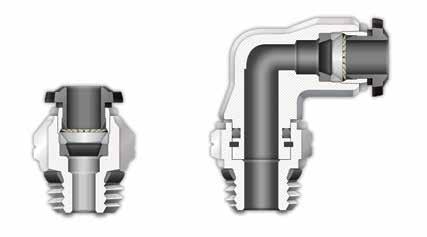
Advantages:

1 The 303 Stainless Steel gripper ensures a tight clamp for tubes of any material without damaging the tube’s surface. The secure connection between the tube and the fitting will hold up to severe conditions such as impact and vibrations.
2 The shape of the safety ring and the molded seal perfectly seal off the tube, creating a vacuum.
3 Series with several types of threads: SWIFTFIT NPTF UNF


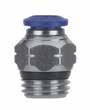
4 All straight fittings can be tightened with an Allen wrench because of our internal hex design. This enables the end user to tighten the fitting in spaces too small for an openend wrench.
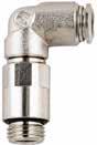
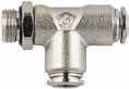
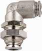
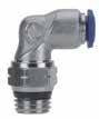
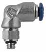
5 Our rotating Swivel Elbow fittings are equipped with a safety ring that enables the fitting to rotate without losing a tight seal.
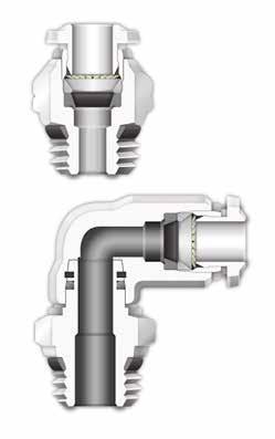
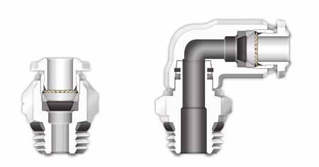
Component Parts and Materials
1 Metallic Release Collet
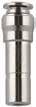
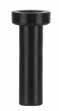
2 Nickel Plated Brass Body
3 NBR Thread Seal
4 Nickel Plated Brass Sleeve
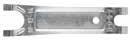
5 303 Stainless Steel Gripper
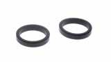
6 Technopolymer Safety Ring
7 NBR Molded Seal
8 Nickel Plated Thread Brass Body
9 NBR Seal

10 Safety Ring
Tubing Compatibility
Nylon 6 - 11 -12
Polyethylene
Polyurethane (“98 Shore A for best result) PTFE FEP
1.3 89 Serie s
1907/2006 2011/65/CE PED 2014/68/UE ISO 14743:2004 SILICON FREE
Reference Standard
1 2 3 4 5 6 7 9 10 NBR -4º F ~ 176º F -20º C ~ 80º C EPDM on request -40º F ~ 266º F -40º C ~ 130º C FKM on request 5º F ~ 266º F -15º C ~ 130º C Temperatures Rating 1 3 4 5 2
Applications
Pneumatic Automation Automotive
8 Page 13
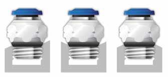
THREADS & ADVANTAGES
One fitting... Endless possibilities
The SWIFTFIT Universal Thread has been designed to offer the following advantages to the end users:
• Reduced overall length
• Smaller hex dimensions compared to parallel threads
• Fits with various parallel and tapered threads
• All SWIFTFIT fittings have been equipped with threads and an NBR thread seal that will universally connect to all thread types.
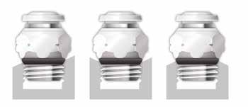
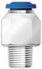
Inclined Concave Convex
Our SWIFTFIT universal fittings also work on non-flat surfaces without compromising an air-tight seal.
UNF Threads
The UNF Thread has been designed to offer the following advantages to the end users:

• Standard USA design
• Designed for use in UNF connections with an integrated NBR o-ring that provides a perfect seal
• Completely reusable
1.4 89 Serie s NPT NPTF Tapered ISO 228 BSP PF Parallell ISO 7 BSPT PT Tapered ISO 7 BSPP Parallell
Torque Specifications Recommended Torque Thread Size Min. Max. 1/8 5 Nm 7 Nm 1/4 5 Nm 7 Nm 3/8 5 Nm 7 Nm 1/2 5 Nm 7 Nm Torque Specifications Recommended Torque Thread Size Min. Breaking torque 10/32 0.8 Nm 3.2 Nm
Page 14
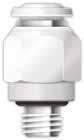
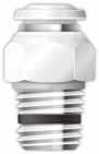
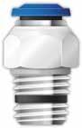
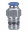
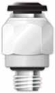
89000
STRAIGHT MALE
* For part numbers with 10-32 threads
89010
STRAIGHT MALE WITH INTERNAL HEX
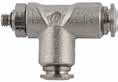
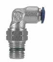
89110
SWIVEL ELBOW


.177(4,5).689(17,5).689(17,5).354(9).315(8).394(10)
.177(4,5).827(21).768(19,5).433(11).433(11).492(12,5)
.217(5,5).827(21).846(21,5).433(11).511(13).493(12,5)
.276(7).827(21).906(23).433(11).591(15).493(12,5)
.295(7,5).827(21).926(23,5).433(11).669(17).493(12,5)
* For part numbers with 10-32 threads
.295(7,5).886(22,5).906(23).472(12).669(17).571(14,5)
.354(9).886(22,5)1.004(25,5).472(12).511(13).571(14,5)
.217(5,5)1.043(26,5).945(24).551(14).551(14).669(17,5)
89110-06-043/81/4 .276(7)1.043(26,5)1.043(26,5).551(14).630(16).669(17,5)
89110-06-063/83/8 .295(7,5)1.043(26,5).965(24,5).551(14).669(17).669(17,5)

89110-06-083/81/2 .354(9)1.043(26,5)1.063(27).551(14).827(21).669(17,5)
89110-08-041/21/4 .276(7)1.240(31,5)1.130(28,7).630(16).630(16).846(21,5)
89110-08-061/23/8 .295(7,5)1.240(31,5)1.043(26,5).630(16).669(17).846(21,5)
89110-08-081/21/2 .354(9)1.240(31,5)1.142(29).630(16).827(21).846(21,5)
1.5 89 Serie s
Part No. TubeA BCLCH1CH2 *89000-02-321/810/32 .197(5).310(8).748(19).315(8).079(2) 89000-02-021/81/8 .217(5,5)-.650(16,5).433(11).079(2) 89000-02-041/81/4 .276(7)-.728(18,5).551(14).079(2) *89000-53-32 5/32 (4) 10/32 .197(5).310(8).827(21).394(10).079(2) 89000-53-02 5/32 (4) 1/8 .217(5,5)-.709(18).433(11).118(3) 89000-53-04 5/32 (4) 1/4 .276(7)-.748(19).551(14).118(3) *89000-04-321/410/32 .197(5).390(10).966(24,5).512(13).079(2) 89000-04-021/41/8 .217(5,5)-.846(21,5).512(13).157(4) 89000-04-041/41/4 .276(7)-.807(20,5).551(14).157(4) 89000-04-061/43/8 .295(7,5)-.905(23).669(17).157(4) 89000-05-02 5/16 (8) 1/8 .217(5,5)-.965(24,5).551(14).197(5) 89000-05-04 5/16 (8) 1/4 .276(7)-.866(22).551(14).236(6) 89000-05-06 5/16 (8) 3/8 .295(7,5)-.906(23).669(17).236(6) 89000-05-08 5/16 (8) 1/2 .354(9)-.925(23,5).827(21).236(6) 89000-06-023/81/8 .217(5,5)-1.082(27,5).669(17).197(5) 89000-06-043/81/4 .276(7)-1.082(27,5).669(17).276(7) 89000-06-063/83/8 .295(7,5)-1.023(25,5).669(17).276(7) 89000-06-083/81/2 .354(9)-1.023(25,5).827(21).276(7) 89000-08-021/21/8 .217(5,5)-1.260(32).787(20).197(5) 89000-08-041/21/4 .276(7)-1.222(31).787(20).276(7) 89000-08-061/23/8 .295(7,5)-1.222(31).787(20).354(9) 89000-08-081/21/2 .354(9)-1.222(31).827(21).394(10) CH1 CH2 B L A UNF CH2 B A C L CH1 Part No. TubeA BCLCH 89010-53-02 5/32 (4) 1/8 .295(7,5).394(10).748(19).118(3) 89010-05-02 5/16 (8) 1/8 .295(7,5).551(14)1.004(25,5).197(5) 89010-05-04 5/16 (8) 1/4 .433(11).551(14).984(25).236(6) A C L B CH Part No. TubeA BL1L2CH1CH2D *89110-02-321/810/32 .177(4,5).630(16).689(17,5).354(9).315(8).394(10) 89110-02-021/81/8
89110-02-041/81/4
*89110-53-32 5/32 (4) 10/32
89110-53-02 5/32 (4) 1/8
89110-53-04 5/32 (4) 1/4
*89110-04-321/410/32
89110-04-021/41/8
89110-04-041/41/4
89110-04-061/43/8
89110-05-02 5/16 (8) 1/8 .217(5,5).886(22,5).886(22,5).472(12).511(13).571(14,5) 89110-05-04 5/16 (8) 1/4 .276(7).886(22,5).886(22,5).472(12).591(15).571(14,5) 89110-05-06 5/16 (8) 3/8
89100-05-08 5/16 (8) 1/2
89110-06-023/81/8
.217(5,5).650(16,5).768(19,5).354(9).511(13).394(10)
.276(7).650(16,5).827(21).354(9).591(15).394(10)
.217(5,5).708(18).768(19,5).354(9).511(13).394(10)
.276(7).708(18).827(21).354(9).591(15).394(10)
B D L1 L2 CH2 CH1 A A D L1 CH1 CH2 B L2 UNF Page 15
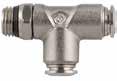
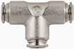
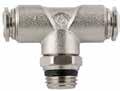
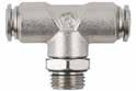
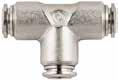
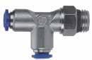
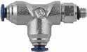
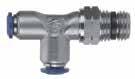
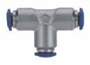
89210
SWIVEL BRANCH TEE
* For part numbers with 10-32 threads
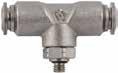
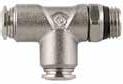
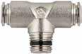
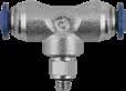
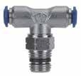
89222
SWIVEL RUN TEE
* For part numbers with 10-32 threads
1.6 89 Serie s
Part No. TubeA BL1L2CH1CH2D *89210-02-321/810/32 .177(4,5)1.300(33).670(17).354(9).315(8).394(10) 89210-02-021/81/8 .216(5,5)1.338(34).669(17).354(9).511(13).394(10) 89210-02-041/81/4 .275(7)1.338(34).787(20).354(9).591(15).394(10) *89210-02-321/810/32 .177(4,5)1.300(33).670(17).354(9).315(8).394(10) 89210-53-02 5/32 (4) 1/8 .216(5,5)1.338(34).787(20).354(9).511(13).394(10) 89210-53-04 5/32 (4) 1/4 .275(7)1.338(34).846(21,5).354(9).591(15).394(10) *89210-04-321/410/32 .177(4,5)1.654(42).807(20,5).433(11).433(11).492(12,5) 89210-04-021/41/8 .216(5,5)1.574(40).787(20).433(11).511(13).493(12,5) 89210-04-041/41/4 .275(7)1.574(40).846(21,5).433(11).629(16).493(12,5) 89210-04-061/43/8 .295(7,5)1.574(40).866(22).433(11).669(17).493(12,5) 89210-05-02 5/16 (8) 1/8 .216(5,5)1.772(45)1.004(25,5).512(13).511(13).571(14,5) 89210-05-04 5/16 (8) 1/4 .275(7)1.772(45)1.004(25,5).512(13).591(15).571(14,5) 89210-05-06 5/16 (8) 3/8 .295(7,5)1.772(45)1.024(26).512(13).669(17).571(14,5) 89210-06-023/81/8 .216(5,5)2.047(52)1.043(26,5).551(14).551(14).669(17,5) 89210-06-043/81/4 .275(7)2.047(52)1.141(29).551(14).630(16).669(17,5) 89210-06-063/83/8 .295(7,5)2.047(52)1.062(27).551(14).669(17).669(17,5) 89210-06-083/81/2 .354(9)2.047(52)1.220(31).551(14).827(21).669(17,5) 89210-08-041/21/4 .275(7)2.402(61)1.240(31,5).630(16).630(16).846(21,5) 89210-08-061/23/8 .295(7,5)2.402(61)1.161(29,5).630(16).669(17).846(21,5) 89210-08-081/21/2 .354(9)2.402(61)1.259(32).630(16).827(21).846(21,5) CH1 D L1 A CH2 B L2 UNF CH2 CH1 L1 D A B L2 Part No. TubeA BL1L2CH1CH2D *89222-02-321/810/32 .177(4,5).650(16,5).670(17).354(9).315(8).394(10) 89222-02-021/81/8 .216(5,5).650(16,5).728(18,5).354(9).511(13).394(10) 89222-02-041/81/4 .334(7).650(16,5).807(20,5).354(9).591(15).394(10) *89222-53-32 5/32 (4) 10/32 .177(4,5).670(17).709(18).354(9).315(8).394(10) 89222-53-02 5/32 (4) 1/8 .216(5,5).649(17).787(20).354(9).511(13).394(10) 89222-53-04 5/32 (4) 1/4 .275(7).649(17).846(21,5).354(9).591(15).394(10) *89222-04-321/410/32 .177(4,5).827(21).807(20,5).433(11).433(11).492(12,5) 89222-04-021/41/8 .216(5,5).846(21,5).787(20).433(11).511(13).493(12,5) 89222-04-041/41/4 .275(7).846(21,5).846(21,5).433(11).591(15).493(12,5) 89222-04-061/43/8 .295(7,5).846(21,5).866(22).433(11).669(17).493(12,5) 89222-05-02 5/16 (8) 1/8 .216(5,5).886(22,5).945(24).512(13).511(13).571(14,5) 89222-05-04 5/16 (8) 1/4 .275(7).886(22,5).945(24).512(13).591(15).571(14,5) 89222-05-06 5/16 (8) 3/8 .295(7,5).886(22,5)1.062(27).512(13).669(17).571(14,5) 89222-06-023/81/8 .216(5,5)1.062(27)1.023(26).551(14).551(14).669(17,5) 89222-06-043/81/4 .275(7)1.062(27)1.043(26,5).551(14).630(16).669(17,5) 89222-06-063/83/8 .295(7,5)1.062(27)1.062(27).551(14).669(17).669(17,5) 89222-06-083/81/2 .354(9)1.062(27)1.141(29).551(14).827(21).669(17,5) 89222-08-041/21/4 .275(7)1.240(31,5)1.240(31,5).630(16).630(16).846(21,5) 89222-08-061/23/8 .295(7,5)1.240(31,5)1.240(31,5).630(16).787(20).846(21,5) 89222-08-081/21/2 .354(9)1.240(31,5)1.279(32,5).630(16).827(21).846(21,5) L1 L1 L2 B A D CH1 CH2 UNF D A B L2 L1 L1 CH1 CH2 Page 16
.531(13,5)M14X1.315(8).630(16).669(17).591(15).826(21)1.417(36)
.531(13,5)M14X1.315(8).787(20).669(17).591(15).826(21)1.417(36)
.374(9,5)M16X1.315(8).709(18).748(19).394(10).866(22)1.260(32)

.531(13,5)M16X1.315(8).709(18).748(19).472(12).866(22)1.339(34)
.531(13,5)M16X1.315(8).787(20).748(19).591(15).866(22)1.457(37)


.531(13,5)M20X1.374(9.5).945(24).945(24).551(14)1.003(25.5)1.557(39,5)
.531(13,5)M22X1.413(10,5).945(24)1.024(26).591(15)1.083(27.5)1.673(42.5) 89055-08-081/21/2 .690(17,5)M22X1.413(10,5).945(24)1.024(26).787(20)1.083(27.5)1.870(47,5)
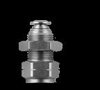
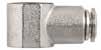
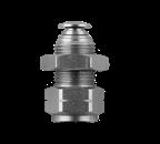
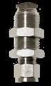
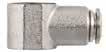
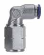
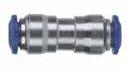
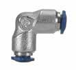
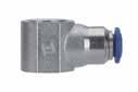
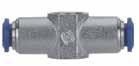
1.7 89 Serie s 89030 STRAIGHT FEMALE 89055 FEMALE BULKHEAD CONNECTOR 89105 FEMALE ELBOW 89040 UNION 89050 BULKHEAD UNION Part No. TubeA BLCH 89030-02-021/81/8 .374(9,5).945(24).512(13) 89030-02-041/81/4 .531(13,5)1.142(29).630(16) 89030-53-02 5/32 (4) 1/8 .374(9,5).965(24.5).512(13) 89030-53-04 5/32 (4) 1/4 .531(13,5)1.161(29,5).630(16) 89030-04-021/41/8 .374(9,5)1.024(26).512(13) 89030-04-041/41/4 .531(13,5)1.220(31).630(16) 89030-06-043/81/4 .531(13,5)1.358(34,5).709(18) 89030-06-063/83/8 .531(13,5)1.358(34,5).787(20) NPTF CH A B L B CH L A Part No. TubeA BMSmaxCH1CH2CDL 89055-53-02 5/32 (4) 1/8 .374(9,5)M12X1.275(7).591(15).669(17).394(10).748(19)1.141(29) 89055-53-04 5/32 (4) 1/4 .531(13,5)M12X1.275(7).630(16).669(17).591(15).748(19)1.339(34) 89055-04-021/41/8 .374(9,5)M14X1.315(8).630(16).669(17).394(10).826(21)1.221(31) 89055-04-041/41/4
89055-04-061/43/8
89055-05-02 5/16 (8) 1/8
89055-05-04 5/16 (8) 1/4
89055-05-06 5/16 (8) 3/8
89055-06-063/83/8
89055-08-061/23/8
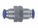
M CH2 L D S max C CH1 A B Part No. TubeA BL1L2CH1CH2D 89105-53-02 5/32 (4) 1/8 .374(9,5).688(17,5).688(17,5).354(9).511(13).394(10) 89105-53-04 5/32 (4) 1/4 .531(13,5).688(17,5).787(20).354(9).629(16).394(10) 89105-04-021/41/8 .374(9,5).846(21,5).748(19).433(11).511(13).492(12,5) 89105-04-041/41/4 .531(13,5).846(21,5).846(21,5).433(11).629(16).492(12,5) 89105-06-023/81/8 .374(9,5)1.062(27).905(23).511(13).511(13).689(17.5) 89105-06-043/81/4 .531(13,5)1.062(27).944(24).629(16).629(16).689(17,5) NPTF L1 D B A CH2 CH1 L2 Part No. TubeTube LB 89040-021/8 .334(8,5)1.023(26) 89040-53 5/32 (4) .413(10,5)1.200(30,5) 89040-04-531/4 5/32 (4) .492(12,5)1.299(33) 89040-041/4 .492(12,5)1.339(34) 89040-05 5/16 (8) .571(14,5)1.417(36) 89040-04-063/81/4 .688(17,5)1.614(41) 89040-06-083/81/2 .807(20,5)1.850(47) 89040-063/8 .688(17,5)1.614(41) 89040-081/2 .807(20,5)1.850(47) B L Part No. TubeM LCHAmax 89050-021/8M10x1 1.023(26).551(14).197(5) 89050-53 5/32 (4) M12x1 1.240(31,5).669(17).276(7) 89050-041/4M14x1 1.378(35).669(17).374(9,5) 89050-05 5/16 (8) M16x1 1.457(37).748(19).413(10,5) 89050-063/8M20x1 1.693(42).945(24).492(12,5) 89050-081/2M22x1 1.890(48)1.024(26).650(16,5) L A max CH M Page 17
NPTF

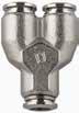
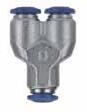
1.8 89 Serie s 89130 ELBOW UNION 89230 UNION TEE 89310 UNION Y 89500 SINGLE BANJO BODY Part No. Tube LCHD 89130-021/8 .649(16,5).354(9).394(10) 89130-53 5/32 (4) .669(17).354(9).394(10) 89130-041/4 .826(21).433(11).492(12,5) 89130-05 5/16 (8) .886(22,5).512(13).551(14) 89130-063/8 1.024(26).630(16).689(17,5) 89130-081/2 1.200(30,5).748(19).846(21,5) CH L L D D L L D Part No. Tube L1L2CHD 89230-021/8 1.229(33).669(17).354(9).394(10) 89230-53 5/32 (4) 1.339(34).669(17).354(9).394(10) 89230-041/4 1.654(42).827(21).433(11).492(12,5) 89230-05 5/16 (8) 1.772(45).866(22,5).512(13).551(14) 89230-063/8 2.087(53)1.043(26,5).630(16).689(17,5) 89230-081/2 2.402(61)1.201(30,5).748(19).846(21,5) CH L1 L2 D D L1 L2 CH Part No. Tube ALCHD 89310-021/8 .394(10)1.142(29).433(11).394(10) 89310-53 5/32 (4) .433(11)1.260(32).433(11).394(10) 89310-041/4 .531(13,5)1.437(36,5).511(13).492(12,5) 89310-05 5/16 (8) .610(15,5)1.514(41).511(13).551(14) 89310-063/8 .728(18,5)1.890(48).708(18).689(17,5) D2 D1 A D2 D L CH Part No. TubeA BLCHD 89500-02-021/81/8 .591(15).748(19).551(14).394(10) 89500-53-32 5/32 (4) 10/32 .492(12,5).748(19)-.394(10) 89500-53-02 5/32 (4) 1/8 .591(15).827(21).551(14).394(10) 89500-04-021/41/8 .591(15).886(22,5).551(14).492(12,5) 89500-04-041/41/4 .669(17).984(25).709(18).492(12,5) 89500-05-02 5/16 (8) 1/8 .591(15).945(24).551(14).551(14) 89500-05-04 5/16 (8) 1/4 .669(17)1.024(26).709(18).551(14) 89500-05-06 5/16 (8) 3/8 .787(20)1.102(28).827(21).551(14) 89500-06-043/81/4 .669(17)1.142(29).709(18).689(17,5) 89500-06-063/83/8 .787(20)1.201(30,5).827(21).689(17,5) 89500-08-061/23/8 .787(20)1.260(32).827(21).846(21,5) 89500-08-081/21/2 .945(24)1.378(35).984(25).846(21,5) ForBANJOSTEMassembliessee10.7/10.8/10.9 A B D L CH Page 18
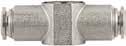
88610B
NYLON PLUG

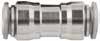
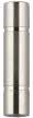
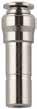
89700 TUBE REDUCER
50980 SECURITY CLIP
50991 TOOL FOR DISASSEMBLING
50006
THREAD PACKING FOR SWIFTFIT TAPER THREADS
1.9 89 Serie s
Part No. Tube L 88610B-021/8 .708(18) 88610B-53 5/32 (4) .925(23,5) 88610B-041/4 .964(24,5) 88610B-05 5/16 (8) 1.023(26) 88610B-063/8 1.122(28,5) 88610B-081/2 1.122(28,5) L Part No. AB LD 89700-04-021/41/8 1.181(30).394(10) 89700-04-531/4 5/32 (4) 1.181(30).394(10) 89700-05-53 5/16 (8)5/32 (4) 1.299(33).394(10) 89700-06-043/81/4 1.397(35,5).492(12,5) 89700-06-053/8 5/16 (8) 1.397(35,5).551(14) 89700-08-041/21/4 1.693(43).492(12,5) 89700-08-061/23/8 1.693(43).689(17,5) B L A D Part No. Tube 50980-53 5/32 (4) 50980-04 1/4 (6) 50980-05 5/16 (8) 50980-06 3/8 (10) 50980-08 1/2 (12) Part No. 50991 468 1012 Part No. Thread 50006-02 1/8 50006-04 1/4 50006-06 3/8 50006-08 1/2 Page 19
1.10 89 Serie s NOTES Page 20
57 Series


Aignep reserves the right to vary models and dimensions without notice


57000 Pg.2.5 57130 Pg.2.10 57115 Pg.2.7 50980 Pg.2.12 57010 Pg.2.5 57230 Pg.2.10 57125 Pg.2.7 50991 Pg.2.12 57110 Pg.2.5 57310 Pg.2.10 57215 Pg.2.8 50006 Pg.2.12 57210 Pg.2.5 57500 Pg.2.10 57225 Pg.2.8 57222 Pg.2.6 57510 Pg.2.11 57100 Pg.2.9 57020 Pg.2.6 50600 Pg.2.11 57200 Pg.2.9 57030 Pg.2.6 50625 Pg.2.11 57050 Pg.2.9 57010 Pg.2.6 57610 Pg.2.11 57040 Pg.2.9 57105 Pg.2.7 57700 Pg.2.11 57060 Pg.2.10 57055 Pg.2.7 57465 Pg.2.9 57326 Pg.2.8 Page 21
57000 Page 22
57 Series METALLIC PUSH-TO-CONNECT FITTINGS FOR METRIC TUBE
Reference Standard
TECHNICAL CHARACTERISTICS
Pressure Rating
Vacuum ~ 290 PSI
-0.99 bar ~ 20 bar
-0.099 MPa ~ 2.0 MPa
Media
• Pneumatic Automation
• Automotive Textile, Packaging
Compressed Air Circuit
• Vacuum
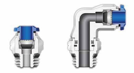
Advantages
1 The 303 Stainless Steel gripper ensures a tight clamp for tubes of any material without damaging the tube’s surface. The secure connection between the tube and the fitting will hold up to severe conditions such as impact and vibrations.
2 The shape of the safety ring and the molded seal perfectly seal off the tube, creating a vacuum.
3 Series with several types of threads: SWIFTFIT BSPP BSPT
4 All straight fittings can be tightened with an Allen wrench because of our internal hex design. This enables the end user to tighten the fitting in spaces too small for an openend wrench.
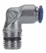
5 Our rotating Swivel Elbow fittings are equipped with a safety ring that enables the fitting to rotate without losing a tight seal.
Component Parts and Materials
1 Metallic Release Collet
2 Nickel Plated Brass Body
3 NBR Thread Seal
4 Nickel Plated Brass Sleeve
5 303 Stainless Steel Gripper
6 Technopolymer Safety Ring
7 NBR Molded Seal
8 Nickel Plated Thread Brass Body
9 NBR Seal
10 Safety Ring
Tubing Compatibility
Nylon 6 - 11 -12
Polyethylene
Polyurethane (“98 Shore A for best result)
PTFE FEP
2.3 57 Serie s
Bar
1907/2006 2011/65/CE PED 2014/68/UE ISO 14743:2004 SILICON FREE
NBR
-20º
C
Applications Pneumatic Automation
Automotive
Textile, Packaging Compressed Air Circuit • Vacuum 1 2 3 4 5 6 7 9 10 8 1 3 4 5 2 Page 23
-4º F ~ 176º F
C ~ 80º
Temperatures Rating
•
•
THREADS & ADVANTAGES
One fitting... Endless possibilities
The SWIFTFIT Universal Thread has been designed to offer the following advantages to the end users:
• Reduced overall length
• Smaller hex dimensions compared to parallel threads
• Fits with various parallel and tapered threads
• All SWIFTFIT fittings have been equipped with threads and an NBR thread seal that will universally connect to all thread types.
Our SWIFTFIT universal fittings also work on non-flat surfaces without compromising an air-tight seal.
BSPP Threads
The BSPP Thread has been designed to offer the following advantages to the end users:
• Standard ISO 228 and ISO R/262
• Designed for use in BSPP connections with an integrated NBR o-ring that provides a perfect seal
• Completely reusable
BSPT Thread with seal
The BSPT Thread has been designed to offer the following advantages to the end users:
• Standard ISO 7.1, BS 21, DN 2999
• Designed for use in BSPT and BSPP connections with an integrated NBR thread seal that provides an additional seal
2.4 57 Serie s NPT NPTF Tapered ISO 228 BSP PF Parallell ISO 7 BSPT PT Tapered ISO 7 BSPP Parallell
Torque Specifications Recommended Torque Thread Size Min. Breaking torque M5 0.8 Nm 0.3 Nm M8 3 Nm 8 Nm 1/8 5 Nm 7 Nm 1/4 5 Nm 7 Nm 3/8 5 Nm 7 Nm 1/2 5 Nm 7 Nm Torque Specifications Recommended Torque Thread Size Min. Breaking torque 1/8 5 Nm 7 Nm 1/4 5 Nm 7 Nm 3/8 5 Nm 7 Nm 1/2 5 Nm 7 Nm Torque Specifications Recommended Torque Thread Size Min. Max. 1/8 5 Nm 7 Nm 1/4 5 Nm 7 Nm 3/8 5 Nm 7 Nm 1/2 5 Nm 7 Nm Inclined Concave Convex Page 24
.275(7)1.043(26,5)1.043(26,5).551(14).629(16).689(17,5)
.295(7,5)1.043(26,5).946(24,5).551(14).669(17).689(17,5)
.354(9)1.043(26,5)1.062(27).551(14).826(21).689(17,5)


57110-12-3/8123/8 .295(7,5)1.240(31,5)1.043(26,5).629(16).787(20).846(21,5)
57110-12-1/2121/2 .354(9)1.240(31,5)1.141(29).629(16).826(21).846(21,5)
57110-14-3/8143/8 .295(7,5)1.240(31,5)1.062(27).629(16).787(20).846(21,5)
57110-14-1/2141/2 .354(9)1.240(31,5)1.161(29,5).629(16).826(21).846(21,5)
2.5 57 Serie s
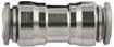
57000
STRAIGHT MALE
57010
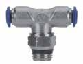
STRAIGHT MALE WITH INTERNAL HEX 57110
SWIVEL ELBOW 57210
Part No. TubeA BLCH1CH2 89000-53-02 4 (5/32) 1/8 .216(5,5).708(18).433(11).118(3) 89000-53-04 4 (5/32) 1/4 .275(7).748(19).551(14).118(3) 57000-6-1/861/8 .216(5,5).846(21,5).511(13).157(4) 57000-6-1/461/4 .275(7).826(21).551(14).157(4) 57000-6-3/863/8 .295(7,5).905(23).669(17).157(4) 57000-6-1/261/2 .354(9).925(23,5).826(21).157(4) 89000-05-02 8 (5/16) 1/8 .216(5,5).964(24,5).551(14).197(5) 89000-05-04 8 (5/16) 1/4 .275(7).866(22).551(14).236(6) 89000-05-06 8 (5/16) 3/8 .295(7,5).905(23).669(17).236(6) 89000-05-08 8 (5/16) 1/2 .354(9).925(23,5).826(21).236(6) 57000-10-1/4101/4 .275(7)1.102(28).669(17).275(7) 57000-10-3/8103/8 .295(7,5)1.003(25,5).669(17).314(8) 57000-10-1/2101/2 .354(9)1.023(25,5).826(21).314(8) 57000-12-1/4121/4 .275(7)1.240(31,5).787(20).275(7) 57000-12-3/8123/8 .295(7,5)1.161(29,5).787(20).354(9) 57000-12-1/2121/2 .354(9)1.240(31,5).826(21).393(10) 57000-14-3/8143/8 .295(7,5)1.279(32,5).826(21).354(9) 57000-14-1/2141/2 .354(9)1.240(31,5).826(21).393(10) CH1 CH2 B L A Part No. TubeA BCLCH 89010-53-02 5/32 (4) 1/8 .217(5,5).433(11).709(18).118(3) 57010-6-1/861/8 .217(5,5).472(12).867(21,5).157(4) 57010-6-1/461/4 .276(7).551(14).827(21).157(4) 89010-05-02 5/16 (8) 1/8 .217(5,5).551(14).984(25).196(5) 89010-05-04 5/16 (8) 1/4 .276(7).551(14).886(22,5).236(6) A C L B CH Part No. TubeA BL1L2CH1CH2D 89110-53-02 5/32 (4) 1/8 .216(5,5).708(18).767(19,5).354(9).512(13).394(10) 89110-53-04 5/32 (4) 1/4 .275(7).748(19).826(21).354(9).590(15).394(10) 57110-6-1/861/8 .216(5,5).826(21).846(21,5).433(11).512(13).492(12,5) 57110-6-1/461/4 .275(7).826(21).905(23).433(11).590(15).492(12,5) 89110-05-02 5/16 (8) 1/8 .216(5,5).885(22,5).885(22,5).472(12).512(13).571(14,5) 89110-05-04 5/16 (8) 1/4 .275(7).885(22,5).885(22,5).472(12).590(15).571(14,5) 89110-05-06 5/16 (8) 3/8 .295(7,5).885(22,5).905(23).472(12).669(17).571(14,5) 89110-05-08 5/16 (8) 1/2 .354(9).885(22,5)1.003(25,5).472(12).826(21).571(14,5) 57110-10-1/4101/4
57110-10-3/8103/8
SWIVEL BRANCH TEE
57110-10-1/2101/2
B D L1 L2 CH2 CH1 A Part No. TubeA BL1L2CH1CH2D 89210-53-02 5/32 (4) 1/8 .216(5,5)1.338(34).787(20).354(9).511(13).394(10) 89210-53-04 5/32 (4) 1/4 .275(7)1.338(34).846(21,5).354(9).590(15).394(10) 57210-6-1/861/8 .216(5,5)1.653(42).866(22).433(11).511(13).492(12,5) 57210-6-1/461/4 .275(7)1.653(42).925(23,5).433(11).590(15).492(12,5) 89210-05-02 5/16 (8) 1/8 .216(5,5)1.771(45)1.003(25,5).511(13).511(13).571(14,5) 89210-05-04 5/16 (8) 1/4 .275(7)1.771(45)1.003(25,5).511(13).590(15).571(14,5) 89210-05-06 5/16 (8) 3/8 .295(7,5)1.771(45)1.023(26).511(13).669(17).571(14,5) 57210-10-1/4101/4 .275(7)2.086(53)1.141(29).551(14).629(16).689(17,5) 57210-10-3/8103/8 .295(7,5)2.086(53)1.062(27).551(14).669(17).689(17,5) 57210-10-1/2101/2 .354(9)2.086(53)1.161(29,5).551(14).826(21).689(17,5) 57210-12-3/8123/8 .295(7,5)2.460(62,5)1.161(29,5).629(16).787(20).846(21,5) 57210-12-1/2121/2 .354(9)2.460(62,5)1.259(32).629(16).826(21).846(21,5) CH1 D L1 A CH2 B L2 Page 25
57020-6-M56M5


57020-6-3/863/8
2.6 57 Serie s
MALE
MALE WITH INTERNAL
FEMALE Part No. TubeA BL1L2CH1CH2D 89222-53-02 5/32 (4) 1/8 .216(5,5).669(17).787(20).354(9).511(13).394(10) 89222-53-04 5/32 (4) 1/4 .275(7).669(17).846(21,5).354(9).590(15).394(10) 57222-6-1/861/8 .216(5,5).826(21).866(22).433(11).511(13).492(12,5) 57222-6-1/461/4 .275(7).826(21).925(23,5).433(11).590(15).492(12,5) 89222-05-02 5/16 (8) 1/8 .216(5,5).885(22,5).944(24).511(13).511(13).571(14,5) 89222-05-04 5/16 (8) 1/4 .275(7).885(22,5).944(24).511(13).590(15).571(14,5) 89222-05-06 5/16 (8) 3/8 .295(7,5).885(22,5)1.062(27).511(13).669(17).571(14,5) 57222-10-1/4101/4 .275(7)1.043(26,5)1.023(26).551(14).629(16).689(17,5) 57222-10-3/8103/8 .295(7,5)1.043(26,5)1.023(26).551(14).669(17).689(17,5) 57222-10-1/2101/2 .354(9)1.043(26,5)1.122(28,5).551(14).826(21).689(17,5) 57222-12-3/8123/8 .295(7,5)1.240(31,5)1.161(29,5).629(16).787(20).847(21,5) 57222-12-1/2121/2 .354(9)1.240(31,5)1.259(32).629(16).826(21).847(21,5) L1 L1 L2 B A D CH1 CH2 Part No. TubeA BCLCH1CH2 57020-4-M5 5/32 (4) M5 .157(4).315(8).827(21).394(10).079(2) 57020-4-1/8 5/32 (4) 1/8 .236(6).512(13).787(20).394(10).118(3) 57020-4-1/4 5/32 (4) 1/4 .315(8).630(16).768(19,5).630(16).118(3) 57020-4-3/8 5/32 (4) 3/8 .315(8).787(20).708(18).787(20).118(3) 57020-5-M55M5 .157(4).315(8).925(23,5).472(12).079(2) 57020-5-1/851/8 .236(6).512(13).866(22).472(12).157(4)
57222 SWIVEL RUN TEE 57020 STRAIGHT
57010 STRAIGHT
HEX 57030 STRAIGHT
.157(4).394(10).965(24,5).512(13).079(2)
57020-6-1/861/8 .236(6).512(13).925(23,5).512(13).157(4)
57020-6-1/461/4 .315(8).630(16).925(23,5).512(13).157(4)
.394(10).984(25)1.063(27).512(13).157(4) 57020-8-1/8 5/16 (8) 1/8 .236(6).512(13).984(25).551(14).197(5) 57020-8-1/4 5/16 (8) 1/4 .315(8).630(16).906(23).551(14).236(6) 57020-8-3/8 5/16 (8) 3/8 .354(9).787(20).945(24).551(14).236(6) 57020-8-1/2 5/16 (8) 1/2 .394(10).984(25)1.043(26,5).551(14).236(6) 57020-10-1/4101/4 .315(8).630(16)1.201(30,5).669(17).236(6) 57020-10-3/8103/8 .354(9).787(20)1.083(27,5).669(17).315(8) 57020-10-1/2101/2 .394(10).984(25)1.063(27).669(17).315(8) 57020-12-1/4121/4 .315(8).630(16)1.358(34,5).787(20).236(6) 57020-12-3/8123/8 .354(9).787(20)1.339(34).787(20).315(8) 57020-12-1/2121/2 .394(10).984(25)1.220(31).866(22).394(10) 57020-14-3/8143/8 .354(9).787(20)1.378(35).827(21).394(10) 57020-14-1/2141/2 .394(10).984(25)1,260(32).866(22).394(10) 57020-6-M8X16M8X1 .216(5,5).472(12).965(24,5).512(13).118(3) 57020-6-M10X16M10X1 .216(5,5).512(13).905(23).512(13).157(4) 57020-6-M12x16M12X1 .315(8).591(15).925(23,5).512(13).157(4) 57020-6-M12x1.256M12X1,25 .315(8).591(15).925(23,5).512(13).157(4) 57020-6-M12x1.56M12X1,5 .315(8).591(15).925(23,5).512(13).157(4) 57020-8-M8x18M8X1 .216(5,5).472(12)1.003(25,5).551(14).157(4) 57020-8-M10x18M10X1 .216(5,5).512(13)1.003(25,5).551(14).157(4) 57020-8-M12x1.58M12X1,5 .315(8).591(15)1.083(27,5).551(14).236(6) BSPP CH2 B CH 1 A C L Part No. TubeA BCLCH 57010-4-M5 5/32 (4) M5 .157(4).394(10).827(21).098(2,5) 57010-4-M7x1 5/32 (4) M7x1 .196(5).394(10).826(21).098(2,5) 57010-6-M56M5 .157(4).472(12).965(24,5).098(2,5) BSPP C A CH L B Part No. TubeA BLCH 57030-4-M5 5/32 (4) M5 .216(5,5).826(21).433(11) 57030-4-1/8 5/32 (4) 1/8 .334(8,5).944(24).511(13) 57030-4-1/4 5/32 (4) 1/4 .433(11)1.082(27,5).629(16) 57030-5-1/851/8 .334(8.5)1.043(26,5).511(13) 57030-6-1/861/8 .334(8,5)1.023(26).511(13) 57030-6-1/461/4 .433(11)1.161(29,5).629(16) 57030-8-1/8 5/16 (8) 1/8 .334(8,5)1.062(27).590(15) 57030-8-1/4 5/16 (8) 1/4 .433(11)1.161(29,5).669(17) 57030-8-3/8 5/16 (8) 3/8 .472(12)1.259(32).748(19) 57030-10-1/4101/4 .433(11)1.259(32).708(18) 57030-10-3/8103/8 .472(12)1.318(33,5).748(19) 57030-10-1/2101/2 .590(15)1.535(39).944(24) 57030-12-3/8123/8 .472(12)1.417(36).826(21) 57030-12-1/2121/2 .590(15)1.614(41).944(24)
CH A B L CH A Page 26
.354(9).787(20).984(25).512(13).157(4) 57020-6-1/261/2
BSPP
57055
FEMALE BULKHEAD CONNECTOR


57105
FEMALE ELBOW
57115
SWIVEL ELBOW
57125
SWIVEL ELBOW
Part No. TubeA BMSmaxCH1CH2CDL
57055-4-1/841/8 .334(8,5)M12X1.275(7).591(15).669(17).394(10).748(19)1.141(29)
57055-6-1/861/8 .334(8,5)M14X1.315(8).630(16).669(17).394(10).826(21)1.221(31)
57055-6-1/461/4 .433(11)M14X1.315(8).630(16).669(17).472(12).826(21)1.300(33)
57055-8-1/881/8 .334(8,5)M16X1.315(8).709(18).748(19).394(10).866(22)1.260(32)
57055-8-1/481/4 .433(11)M16X1.315(8).709(18).748(19).472(12).866(22)1.339(34)
57055-10-3/8103/8 .472(12)M20X1.374(9.5).945(24).945(24).551(14)1.003(25.5)1.556(38,5)
57055-12-3/8123/8 .472(12)M22X1.413(10,5).945(24)1.024(26).591(15)1.083(27.5)1.673(42.5)
57055-12-1/2121/2 .591(15)M22X1.413(10,5).945(24)1.024(26).669(17)1.083(27.5)1.752(44.5)
.334(8,5).826(21).807(20,5).433(11).511(13).492(12,5)
.433(11).826(21).905(23).433(11).629(16).492(12,5)
.334(8,5).885(22,5).807(20,5).472(12).511(13).571(14,5)
.433(11).885(22,5).905(23).472(12).629(16).571(14,5) 57105-10-1/4101/4 .433(11)1.043(26,5).984(25).551(14).748(19).669(17)
57105-10-3/8103/8 .472(12)1.043(26,5)1.201(28).551(14).748(19).669(17)
57105-12-1/2121/2 .591(15)1.240(31,5)1.358(34).630(16).945(24).787(20)
.138(3,5).787(20).787(20).433(11).433(11).492(12,5)
57115-5-1/851/8 .217(5,5).787(20).787(20).433(11).512(13).492(12,5)
57115-6-M56M5 .138(3,5).827(21).787(20).433(11).433(11).492(12,5)
57115-6-1/861/8 .217(5,5).827(21).787(20).433(11).512(13).492(12,5)
.374(9,5)1.043(26,5)1.043(26,5).551(14).984(25).689(17,5)
57115-12-1/4121/4 .315(8)1.240(31,5)1.083(27,5).63(16).787(20).846(21,5)
57115-12-3/8123/8 .315(8)1.240(31,5)1.063(27).63(16).787(20).846(21,5)
57115-12-1/2121/2 .374(9,5)1.240(31,5)1.122(28,5).63(16).984(25).846(21,5)
57115-14-3/8143/8 .315(8)1.240(31,5)1.083(27,5).63(16).787(20).846(21,5)
57115-14-1/2141/2 .374(9,5)1.240(31,5)1.142(29).63(16).984(25).846(21,5)
57115-6-M12x16M12x1 .295(7,5).787(20).866(22).433(11).630(16).492(12,5)
57115-6-M12x1.25 6M12x1,25 .295(7,5).787(20).866(22).433(11).630(16).492(12,5)
57115-6-M12x1.5 6M12x1,5 .295(7,5).787(20).866(22).433(11).630(16).492(12,5)
57115-8-M12x1.5 8M12x1,5 .295(7,5).886(22,5).866(22).472(12).630(16).571(14,5)
.217(5,5).787(20)1.358(34,5).433(11).472(12).492(12,5)
.217(5,5).827(21)1.358(34,5).433(11).472(12).492(12,5)
.276(7).827(21)1.417(36).433(11).591(15).492(12,5)
.197(5).898(22,8)1.476(37,5).472(12).472(12).571(14,5)
2.7 57 Serie s
BSPP M CH2 L D S max C CH1 A B Part No. TubeA BL1L2CH1CH2D 57105-4-1/8 5/32 (4) 1/8 .334(8,5).708(18).787(20).354(9).511(13).394(10) 57105-4-1/4 5/32 (4) 1/4 .433(11).708(18).846(21,5).354(9).629(16).394(10) 57105-6-1/861/8
57105-6-1/461/4
57105-8-1/8 5/16 (8) 1/8
57105-8-1/4 5/16 (8) 1/4
BSPP L1 D B A CH2 CH1 L2
No. TubeA BL1L2CH1CH2D 57115-4-M5 5/32 (4) M5
57115-4-1/8 5/32 (4) 1/8
57115-4-1/4 5/32 (4) 1/4 .276(7).709(18).709(18).354(9).63(16).394(10) 57115-5-M55M5
Part
.138(3,5).709(18).689(17,5).354(9).315(8).394(10)
.217(5,5).709(18).709(18).354(9).512(13).394(10)
57115-6-1/461/4 .276(7).827(21).846(21,5).433(11).630(16).492(12,5) 57115-6-3/863/8 .276(7).827(21).846(21,5).433(11).630(16).492(12,5) 57115-8-1/8 5/16 (8) 1/8 .217(5,5).886(22,5).827(21).472(12).512(13).571(14,5) 57115-8-1/4 5/16 (8) 1/4 .276(7).886(22,5).846(21,5).472(12).63(16).571(14,5) 57115-8-3/8 5/16 (8) 3/8 .315(8).886(22,5).925(23,5).472(12).787(20).571(14,5) 57115-8-1/2 5/16 (8) 1/2 .374(9,5).886(22,5).984(25).472(12).984(25).571(14,5) 57115-10-1/4101/4 .276(7)1.043(26,5)1.004(25,5).551(14).630(16).689(17,5) 57115-10-3/8103/8
57115-10-1/2101/2
.315(8)1.043(26,5).984(25).551(14).787(20).689(17,5)
A D L1 CH1 CH2 B L2 Part No. TubeA BL1L2CH1CH2D
5/32 (4) 1/8
57125-4-1/4 5/32 (4) 1/4 .276(7).709(18)1.260(32).354(9).591(15).394(10) 57125-5-1/851/8
57125-6-1/861/8
57125-6-1/461/4
57125-8-1/8 5/16 (8) 1/8
57125-8-1/4 5/16 (8) 1/4 .276(7).886(22,5)1.496(38).472(12).591(15).571(14,5) 57125-8-3/8 5/16 (8) 3/8 .315(8).886(22,5)1.575(40).472(12).709(18).571(14,5) 57125-10-1/4101/4 .276(7)1.043(26,5)1.772(45).551(14).630(16).689(17,5) 57125-10-3/8103/8 .315(8)1.043(26,5)1.752(44,5).551(14).709(18).689(17,5) BSPP CH1 CH2 A B L2 D L1 Page 27
BSPP
57125-4-1/8
.217(5,5).709(18)1.181(30).354(9).472(12).394(10)
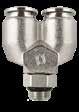
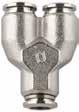
57326
Y-CONNECTOR MALE ADAPTOR (PARALLEL)
2.8 57 Serie s
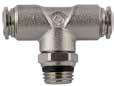
57215 SWIVEL BRANCH TEE
RUN TEE
57225 SWIVEL
Part No. TubeA BL1L2CH1CH2D 57215-4-M5 5/32 (4) M5 .138(3,5)1.339(34).709(18).354(9).315(8).394(10) 57215-4-1/8 5/32 (4) 1/8 .217(5,5)1.339(34).728(18,5).354(9).512(13).394(10) 57215-4-1/4 5/32 (4) 1/4 .276(7)1.339(34).787(20).354(9).630(16).394(10) 57215-5-M55M5 .138(3,5)1.575(40).807(20,5).433(11).433(11).492(12,5) 57215-5-1/851/8 .217(5,5)1.575(40).807(20,5).433(11).512(13).492(12,5) 57215-6-M56M5 .138(3,5)1.654(42).807(20,5).433(11).433(11).492(12,5) 57215-6-1/861/8 .217(5,5)1.654(42).807(20,5).433(11).512(13).492(12,5) 57215-6-1/461/4 .276(7)1.654(42).866(22).433(11).630(16).492(12,5) 57215-8-1/8 5/16 (8) 1/8 .217(5,5)1.772(45).925(23,5).512(13).512(13).571(14,5) 57215-8-1/4 5/16 (8) 1/4 .276(7)1.772(45).945(24).512(13).630(16).571(14,5) 57215-8-3/8 5/16 (8) 3/8 .315(8)1.772(45)1.024(26).512(13).787(20).571(14,5) 57215-8-1/2 5/16 (8) 1/2 .374(9,5)1.772(45)1.083(27,5).512(13).984(25).571(14,5) 57215-10-1/4101/4 .276(7)2.087(53)1.083(27,5).551(14).630(16).689(17,5) 57215-10-3/8103/8 .315(8)2.087(53)1.063(27).551(14).787(20).689(17,5) 57215-10-1/2101/2 .374(9,5)2.087(53)1.122(28,5).551(14).984(25).689(17,5) 57215-12-3/8123/8 .315(8)2.461(62,5)1.161(29,5).630(16).787(20).846(21,5) 57215-12-1/2121/2 .374(9,5)2.461(62,5)1.220(31).630(16).984(25).846(21,5) 57215-14-3/8143/8 .315(8)2.461(62,5)1.161(29,5).630(16).787(20).846(21,5) 57215-14-1/2141/2 .374(9,5)2.461(62,5)1.220(31).630(16).984(25).846(21,5) 57215-6-M12x16M12x1 .295(7,5)1.654(42).866(22).433(11).630(16).492(12,5) 57215-6-M12x1.25 6M12x1,25 .295(7,5)1.654(42).866(22).433(11).630(16).492(12,5) 57215-6-M12x1.5 6M12x1,5 .295(7,5)1.654(42).866(22).433(11).630(16).492(12,5) BSPP CH2 CH1 L1 D A B L2 Part No. TubeA BL1L2CH1CH2D 57225-4-M5 5/32 (4) M5 .138(3,5).669(17).709(18).354(9).315(8).394(10) 57225-4-1/8 5/32 (4) 1/8 .217(5,5).669(17).728(18,5).354(9).512(13).394(10) 57225-4-1/4 5/32 (4) 1/4 .276(7).669(17).787(20).354(9).63(16).394(10) 57225-5-M55M5 .138(3,5).787(20).807(20,5).433(11).433(11).492(12,5) 57225-5-1/851/8 .217(5,5).787(20).807(20,5).433(11).512(13).492(12,5) 57225-6-M56M5 .138(3,5).827(21).807(20,5).433(11).433(11).492(12,5) 57225-6-1/861/8 .217(5,5).827(21).807(20,5).433(11).512(13).492(12,5) 57225-6-1/461/4 .276(7).827(21).866(22).433(11).63(16).492(12,5) 57225-8-1/8 5/16 (8) 1/8 .217(5,5).886(22,5).886(22,5).512(13).512(13).571(14,5) 57225-8-1/4 5/16 (8) 1/4 .276(7).886(22,5).906(23).512(13).63(16).571(14,5) 57225-8-3/8 5/16 (8) 3/8 .315(8).886(22,5).984(25).512(13).787(20).571(14,5) 57225-8-1/2 5/16 (8) 1/2 .374(9,5).886(22,5)1.043(26,5).512(13).984(25).571(14,5) 57225-10-1/4101/4 .276(7)1.043(26,5)1.063(27).551(14).63(16).689(17,5) 57225-10-3/8103/8 .315(8)1.043(26,5)1.043(26,5).551(14).787(20).689(17,5) 57225-10-1/2101/2 .374(9,5)1.043(26,5)1.102(28).551(14).984(25).689(17,5) 57225-12-3/8123/8 .315(8)1.240(31,5)1.161(29,5).63(16).787(20).846(21,5) 57225-12-1/2121/2 .374(9,5)1.240(31,5)1.220(31).63(16).984(25).846(21,5) 57225-6-M12x16M12x1 .295(7,5).827(21).866(22).433(11).63(16).492(12,5) 57225-6-M12x1.25 6M12x1,25 .295(7,5).827(21).866(22).433(11).63(16).492(12,5) 57225-6-M12x1.5 6M12x1,5 .295(7,5).827(21).866(22).433(11).63(16).492(12,5) BSPP D A B L2 L1 L1 CH1 CH2 Part No. TubeA BCCH1CH2D 57326-4-1/8 5/32 (4) 1/8 .217(5,5)1.280(32,5).511(13).433(11).394(10) 57326-6-1/861/8 .217(5,5)1.456(37).511(13).511(13).492(12,5) 57326-6-1/461/4 .275(7)1.516(38,5).629(16).511(13).492(12,5) 57326-8-1/8 5/16 (8) 1/8 .217(5,5)1.594(40,5).511(13).590(15).551(14) 57326-8-1/4 5/16 (8) 1/4 .275(7)1.614(41).629(16).590(15).551(14) 57326-8-3/8 5/16 (8) 3/8 .314(8)1.693(43).787(20).590(15).551(14) BSPP A B L C CH2 CH1 D Page 28
BSPT L1 L 2 B A
D
57100-8-1/4 5/16 (8) 1/4 .433(11).886(22,5).846(21,5).512(13).551(14)
57100-10-1/4101/4 .433(11)1.043(26,5).965(24,5).63(16).669(17)

57100-10-3/8103/8 .453(11,5)1.043(26,5).945(24).63(16).669(17)
57100-12-1/4121/4 .433(11)1.201(30,5)1.201(28).748(19).846(21,5)
Part No. TubeA BL1L2CHD

57200-4-M5
57200-4-1/8
5/32 (4)
5/32 (4) 1/8
57200-5-1/851/8 .295(7,5)1.575(40).689(17,5).433(11).492(12,5)
57200-6-1/861/8 .295(7,5)1.654(42).689(17,5).433(11).492(12,5)
57200-8-1/8 5/16 (8) 1/8 .295(7,5)1.772(45).748(19).512(13).551(14) 57200-8-1/4 5/16 (8) 1/4 .433(11)1.772(45).846(21,5).512(13).551(14) 57200-10-1/4101/4 .433(11)2.087(53).965(24,5).63(16).669(17) 57200-10-3/8103/8 .453(11,5)2.087(53).945(24).63(16).669(17) 57200-12-1/4121/4 .433(11)2.402(61)1.102(28).748(19).846(21,5) 57200-12-3/8123/8 .453(11,5)2.402(61)1.102(28).748(19).846(21,5) BSPT CH L1 D A B L2 Part No. TubeTube LB 89040-53 5/32 (4) 1.200(30,5).413(10,5) 57040-55 1.299(33).453(11,5) 57040-6-46 5/32 (4) 1.259(32).492(12,5) 57040-66 1.338(34).492(12,5) 57040-8-6 5/16 (8) 6 1.377(35).571(14,5) 89040-05 5/16 (8) 1.417(36).571(14,5) 57040-10-810 5/16 (8) 1.594(40,5).689(17,5) 57040-1010 1.653(42).689(17,5) 57040-12-101210 1.791(45,5).807(20,5) 57040-1212 1.850(47).807(20,5) 57040-1414 1.929(49).846(21,5) B L Part No. TubeM LCHAmax 89050-53 5/32 (4) M12x1 1.240(31,5).669(17).275(7) 57050-55M14x1 1.299(33).669(17).275(7) 57050-66M14x1 1.377(35).669(17).374(9,5) 57050-8-6 5/16 (8)-6 M16x1 1.456(37).748(19).413(10,5) 89050-05 5/16 (8) M16x1 1.456(37).748(19).413(10,5) 57050-10-610-6M20x1 1.693(43).945(24).453(11,5) 57050-10-8 10-5/16 (8) M20x1 1.693(43).945(24).492(12,5) 57050-1010M20x1 1.692(42).944(24).492(12,5) 57050-1212M22x1 1.889(48)1.023(26).649(16,5) L A max CH M Part No. Tube LDCH1CH2CH3 57465-66 1.949(49.5).492(12.5).511(13).669(17).669(17) 57465-8 5/16 (8) 2.047(52).551(14).551(14).748(19).748(19) 57465-1010 2.282(59).669(17).748(19).945(24).945(24) L ØD CH3 CH1 CH2 Page 29
2.9 57 Serie s 57100 FIXED ELBOW 57200 FIXED BRANCH TEE 57040 UNION 57050 BULKHEAD UNION
BULKHEAD CONNECTOR Part No. TubeA BL1L2CHD 57100-4-M5 5/32 (4) M5 .197(5).669(17).591(15).354(9).394(10) 57100-4-1/8 5/32 (4) 1/8 .295(7,5).669(17).61(15,5).354(9).394(10) 57100-5-M55M5 .197(5).787(20).669(17).433(11).492(12,5) 57100-5-1/851/8 .295(7,5).787(20).689(17,5).433(11).492(12,5) 57100-6-1/861/8 .295(7,5).827(21).689(17,5).433(11).492(12,5) 57100-6-1/461/4 .433(11).827(21).846(21,5).433(11).492(12,5) 57100-8-1/8 5/16 (8) 1/8 .295(7,5).886(22,5).748(19).512(13).551(14)
57465
57100-12-3/8123/8 .453(11,5)1.201(30,5)1.201(28).748(19).846(21,5) CH
M5 .197(5)1.339(34).591(15).354(9).394(10)
.295(7,5)1.339(34).61(15,5).354(9).394(10)

2.10 57 Serie s 57060 SWIVEL ELBOW BULKHEAD 57130 UNION ELBOW 57230 UNION TEE 57310 UNION Y 57500 SINGLE BANJO BODY Part No. TubeM L1L2CHCH1CH2AmaxD 57060-4 5/32 (4) M12x1 .689(17,5)1.024(26).354(9).551(14).669(17).236(6).394(10) 57060-6 6M14x1 .846(21,5)1.220(31).433(11).669(17).669(17).256(6,5).492(12,5) 57060-8 5/16 (8) M16x1 .866(22)1.339(34).472(12).709(18).748(19).256(6,5).571(14,5) 57060-10 10M20x1 1.043(26,5)1.417(36).551(14).866(22).945(24).295(7,5).689(17,5) 57060-12 12M22x1 1.201(30,5)1.693(43).63(16).945(24)1.024(26).354(9).846(21,5) 57060-14 14M23x1 1.201(30,5)1.693(43).63(16).984(25)1.063(27).374(9,5).846(21,5) L1 L2 A max D M CH1 CH2 CH Part No. Tube LCHD 89130-53 5/32 (4) .669(17).354(9).394(10) 57130-55 .787(20).433(11).492(12,5) 57130-66 .826(21).433(11).492(12,5) 89130-05 5/16 (8) .885(22,5).511(13).571(14,5) 57130-1010 1.043(26,5).629(16).689(17,5) 57130-1212 1.200(30,5).748(19).846(21,5) 57130-1414 1.279(32,5).748(19).846(21,5) CH L L D L L D Part No. Tube L1L2CHD 89230-53 5/32 (4) 1.338(34).669(17).354(9).394(10) 57230-55 1.574(40).787(20).433(11).492(12,5) 57230-66 1.653(42).826(21).433(11).492(12,5) 89230-05 5/16 (8) 1.771(45).885(22,5).511(13).551(14) 57230-1010 2.086(53)1.043(26,5).629(16).669(17) 57230-1212 2.401(61)1.200(30,5).748(19).847(21,5) 57230-1414 2.578(65,5)1.279(32,5).748(19).847(21,5) CH L1 L2 D D L1 L2 CH Part No. Tube ALCHD 89310-53 5/32 (4) .433(11)1.259(32).433(11).394(10) 57310-55 .531(13,5)1.377(35).511(13).492(12,5) 57310-66 .531(13,5)1.437(36,5).511(13).492(12,5) 89310-05 5/16 (8) .610(15,5)1.614(41).590(15).551(14) 57310-1010 .728(18,5)1.889(48).708(18).669(17) D2 D1 A D2 D L CH Part No. TubeA BLCHD 89500-53-32 5/32 (4) M5 .492(12,5).748(19)-.394(10) 57500-4-M6 5/32 (4) M6 .492(12,5).748(19)-.394(10) 89500-53-02 5/32 (4) 1/8 .591(15).827(21).551(14).394(10) 57500-5-M55M5 .492(12,5).787(20)-.492(12,5) 57500-5-M65M6 .492(12,5).787(20)-.492(12,5) 57500-5-1/851/8 .591(15).846(21,5).551(14).492(12,5) 57500-5-1/451/4 .669(17).965(24,5).709(18).492(12,5) 57500-6-M56M5 .492(12,5).807(20,5)-.492(12,5) 57500-6-M66M6 .492(12,5).807(20,5)-.492(12,5) 57500-6-1/861/8 .591(15).866(22).551(14).492(12,5) 57500-6-1/461/4 .669(17).984(25).709(18).492(12,5) 57500-8-1/8 5/16 (8) 1/8 .591(15).945(24).551(14).551(14) 57500-8-1/4 5/16 (8) 1/4 .669(17)1.024(26).709(18).551(14) 57500-8-3/8 5/16 (8) 3/8 .787(20)1.102(28).827(21).551(14) 57500-10-1/4101/4 .669(17)1.142(29).709(18).669(17) 57500-10-3/8103/8 .787(20)1.201(30,5).827(21).669(17) 57500-12-3/8123/8 .787(20)1.280(32,5).827(21).846(21,5) 57500-12-1/2121/2 .945(24)1.378(35).984(25).846(21,5) 57500-14-1/2141/2 .945(24)1.398(35,5).984(25).846(21,5) ForBANJOSTEMassembliessee10.7/10.8/10.9 A B D L CH Page 30


2.11 57 Serie s
DOUBLE BANJO BODY
STANDPIPE
PLUG
DOUBLE JOINT
TUBE REDUCER Part No. TubeA BLCHD 57510-4-M5 5/32 (4) M5 .492(12,5)1.496(38)-.394(10) 57510-4-M6 5/32 (4) M6 .492(12,5)1.496(38)-.394(10) 57510-4-1/8 5/32 (4) 1/8 .591(15)1.654(42).551(14).394(10) 57510-5-1/851/8 .591(15)1.693(43).551(14).492(12,5) 57510-5-1/451/4 .669(17)1.929(49).709(18).492(12,5) 57510-6-1/861/8 .591(15)1.732(44).551(14).492(12,5) 57510-6-1/461/4 .669(17)1.969(50).709(18).492(12,5) 57510-8-1/8 5/16 (8) 1/8 .591(15)1.890(48).551(14).551(14) 57510-8-1/4 5/16 (8) 1/4 .669(17)2.047(52).709(18).551(14) ForBANJOSTEMassembliessee10.7/10.8/10.9 A B D L CH Part No. DA BLL1CH 50600-4-M5 5/32 (4) M5 .157(4).945(24).591(15).315(8) 50600-4-1/8 5/32 (4) 1/8 .236(6)1.043(26,5).591(15).512(13) 50600-5-M55M5 .157(4)1.024(26).669(17).315(8) 50600-5-1/851/8 .236(6)1.122(28,5).669(17).512(13) 50600-5-1/451/4 .315(8)1.220(31).669(17).630(16) 50600-6-M56M5 .157(4)1.024(26).669(17).315(8) 50600-6-1/861/8 .236(6)1.122(28,5).669(17).512(13) 50600-6-1/461/4 .315(8)1.220(31).669(17).630(16) 50600-8-1/8 5/16 (8) 1/8 .236(6)1.161(29,5).709(18).512(13) 50600-8-1/4 5/16 (8) 1/4 .315(8)1.260(32).709(18).630(16) 50600-8-3/8 5/16 (8) 3/8 .354(9)1.319(33,5).709(18).787(20) 50600-10-1/8101/8 .236(6)1.319(33,5).866(22).512(13) 50600-10-1/4101/4 .315(8)1.417(36).866(22).630(16) 50600-10-3/8103/8 .354(9)1.476(37,5).866(22).787(20) 50600-12-1/4121/4 .315(8)1.516(38,5).965(24,5).630(16) 50600-12-3/8123/8 .354(9)1.575(40).965(24,5).787(20) 50600-14-1/2141/2 .394(10)1.732(44)1.043(26,5).945(24) BSPP D A B CH L1 L Part No. D GLL1 57610-4 5/32 (4) .315(8)1.004(25,5).728(18,5) 57610-55 .315(8)1.063(27).787(20) 57610-66 .315(8)1.083(27,5).807(20,5) 57610-8 5/16 (8) .472(12)1.161(29,5).846(21,5) 57610-1010 .472(12)1.280(32,5).964(24,5) 57610-1212 .630(16)1.437(36,5)1.083(27,5) 57610-1414 .630(16)1.437(36,5)1.043(26,5) L D L1 G Part No. Tube L 50625-4 5/32 (4) 1.220(31) 50625-55 1.299(33) 50625-66 1.339(34) 50625-8 5/16 (8) 1.417(36) 50625-1010 1.772(45) 50625-1212 1.969(50) L Part No. AB LD 57700-5-45 5/32 (4) 1.142(29).413(10,5) 57700-6-46 5/32 (4) 1.181(30).413(10,5) 57700-6-565 1.260(32).435(11,05) 89700-05-53 5/16 (8)5/32 (4) 1.300(33).413(10,5) 57700-8-6 5/16 (8) 6 1.339(34).551(14) 57700-10-410 5/32 (4) 1.260(32).394(10) 57700-10-810 5/16 (8) 1.496(38).571(14,5) 57700-12-812 5/16 (8) 1.535(39).571(14,5) 57700-12-101210 1.693(43).690(17,5) B L A D Page 31
57510
50600
57610
50625
57700
50980
SECURITY CLIP
50991
TOOL FOR DISASSEMBLING

50006
THREAD PACKING FOR THE SWIFTFIT TAPER THREADS
2.12 57 Serie s
Part No. Tube 50980-53 5/32 (4) 50980-04 1/4 (6) 50980-05 5/16 (8) 50980-06 3/8 (10) 50980-08 1/2 (12) Part No. 50991 468 1012 Part No. Thread 50006-02 1/8 50006-04 1/4 50006-06 3/8 50006-08 1/2 Page 32
87 - 88 Series


Fitting Kits
Aignep reserves the right to vary models and dimensions without notice


87000 Pg.3.5 88222 Pg.3.9 88225 Pg.3.7 87800 Pg.3.12 87010 Pg.3.5 88040 Pg.3.10 88007 Pg.3.7 55801 Pg.3.12 87110 Pg.3.5 88050 Pg.3.10 88117 Pg.3.7 55802 Pg.3.12 87210 Pg.3.6 88130 Pg.3.10 88000 Pg.3.8 50980 Pg.3.11 87222 Pg.3.6 88310 Pg.3.10 88030 Pg.3.8 88230 Pg.3.10 88020 Pg.3.6 88500 Pg.3.11 88100 Pg.3.8 88115 Pg.3.7 88610 Pg.3.11 88110 Pg.3.9 87010 Pg.3.6 88510 Pg.3.11 88105 Pg.3.9 88215 Pg.3.7 88700 Pg.3.11 88210 Pg.3.9 88055 Pg.3.8
87861-02 Pg.3.13 87861-90 Pg.3.14 87861-06 Pg.3.13 87861-04 Pg.3.13 87861-08 Pg.3.14 Page 33
8788 Series PUSH-TO-CONNECT FITTINGS FOR INCH TUBE 87000 88000 Page 34
Reference Standard
TECHNICAL CHARACTERISTICS
Bar
Pressure Rating
Vacuum ~ 290 PSI
-0.99 bar ~ 20 bar
-0.099 MPa ~ 2.0 MPa
-4º F ~ 176º F -20º C ~ 80º C
Media
• Compressed air Vacuum Water Steam (FKM required)
Applications
Pneumatic Automation
• Automotive
• Textile, Packaging
• Compressed Air Circuit
• Vacuum
Advantages
1 The 303 Stainless Steel gripper ensures a tight clamp for tubes of any material without damaging the tube’s surface. The secure connection between the tube and the fitting will hold up to severe conditions such as impact and vibrations.
2 The shape of the safety ring and the molded seal perfectly seal off the tube, creating a vacuum.
3 Series with several types of threads: SWIFTFIT UNF PTF NPTF

4 All straight fittings can be tightened with an Allen wrench because of our internal hex design. This enables the end user to tighten the fitting in spaces too small for an openend wrench.
5 Our rotating Swivel Elbow fittings are equipped with a safety ring that enables the fitting to rotate without losing a tight seal.
Component Parts and Materials
1 Composite Release Collet
2 Nickel Plated Brass Body
3 NBR Thread Seal
4 Nickel Plated Brass Sleeve
5 303 Stainless Steel Gripper
6 Technopolymer Safety Ring
7 NBR Molded Seal
8 Nickel Plated Thread Brass Body
9 NBR Seal

10 Safety Ring
Tubing Compatibility
Nylon 6 - 11 -12
Polyethylene
Polyurethane (“98 Shore A for best result)
PTFE FEP
3.3 87 - 88 Serie s 1907/2006 2011/65/CE ISO 14743:2004 SILICON FREE PED 2014/68/UE
NBR
1 2 3 4 5 6 7 9 10 8 1 3 4 5 2 Page 35
Temperatures Rating
THREADS & ADVANTAGES
The SWIFTFIT Universal Thread has been designed to offer the following advantages to the end users:
• Reduced overall length
• Smaller hex dimensions compared to parallel threads
• Fits with various parallel and tapered threads
• All SWIFTFIT fittings have been equipped with threads and an NBR thread seal that will universally connect to all thread types.
Inclined Concave Convex
Our SWIFTFIT universal fittings also work on non-flat surfaces without compromising an air-tight seal.
UNF Thread
The UNF Thread has been designed to offer the following advantages to the end users:

• Standard USA design
• Designed for use in UNF connections with an integrated NBR o-ring that provides a perfect seal
• Completely reusable
PTF Thread
The PTF Thread has been designed to offer the following advantages to the end users:
• Standard USA design. PTF/SAE short thread
• Designed for connections with an NPTF thread
• Dryseal pipe threads are designed for applications where clearance is not sufficient for the full thread length of NPTF threads.
3.4 87 - 88 Serie s
Torque Specifications Recommended Torque Thread Size Min. Max. 1/8 5 Nm 7 Nm 1/4 5 Nm 7 Nm 3/8 5 Nm 7 Nm 1/2 5 Nm 7 Nm NPT NPTF Tapered ISO 228 BSP PF Parallell ISO 7 BSPT PT Tapered ISO 7 BSPP Parallell
fitting...
One
Endless possibilities
Torque Specifications Recommended Torque Thread Size Min. Breaking torque 10/32 0.8 Nm 3.2 Nm Torque Specifications Recommended Torque Thread Size Min. Breaking torque 1/8 5 Nm 8 Nm 1/4 9 Nm 30 Nm
Page 36
NPTF Thread with seal
The NPTF Thread has been designed to offer the following advantages to the end users:
• Standard USA design
• Designed for use in NPT connections with an integrated NBR thread seal that provides an additional seal

3.5 87 - 88 Serie s
Torque Specifications Recommended Torque Thread Size Min. Max. 1/8 5 Nm 7 Nm 1/4 5 Nm 7 Nm 3/8 5 Nm 7 Nm 1/2 5 Nm 7 Nm
STRAIGHT MALE
STRAIGHT MALE WITH INTERNAL HEX
SWIVEL ELBOW Part No. TubeA BLCH1CH2 87000-02-021/81/8 .217(5,5).650(16,5).433(11).079(2) 87000-02-041/81/4 .276(7).728(18,5).551(14).079(2) 87000-53-02 5/32 (4) 1/8 .217(5).708(18).433(11).118(3) 87000-53-04 5/32 (4) 1/4 .276(7).767(19,5).551(14).118(3) 87000-04-021/41/8 .217(5).866(22).512(13).157(4) 87000-04-041/41/4 .276(7).826(21).551(14).157(4) 87000-04-061/43/8 .295(7,5).826(21).669(17).157(4) 87000-05-02 5/16 (8) 1/8 .217(5).964(24,5).551(14).197(5) 87000-05-04 5/16 (8) 1/4 .276(7).866(22).551(14).236(6) 87000-05-06 5/16 (8) 3/8 .295(7,5).905(23).669(17).236(6) 87000-06-023/81/8 .217(5)1.122(28,5).669(17).197(5) 87000-06-043/81/4 .276(7)1.122(28,5).669(17).276(6) 87000-06-063/83/8 .295(7,5)1.043(26,5).669(17).276(6) 87000-06-083/81/2 .354(9)1.043(26,5).827(21).276(6) 87000-08-021/21/8 .217(5)1.299(33).787(20).197(5) 87000-08-041/21/4 .276(7)1.299(33).787(20).197(5) 87000-08-061/23/8 .295(7,5)1.259(32).787(20).354(9) 87000-08-081/21/2 .354(9)1.259(32).827(21).394(10) CH2 L A B CH1 Part Number TubeA BCLCH 87010-53-02 5/32 (4) 1/8 .217(5).374(9.5).709(18).118(3) 87010-04-021/41/8 .217(5).473(12).846(21,5).157(4) 87010-04-041/41/4 .2767(7).551(14).846(21,5).157(4) A C L B CH Part No. TubeA BL1L2CH1CH2 87110-02-021/81/8 .217(5,5).650(16,5).846(21,5).354(9).512(13) 87110-02-041/81/4 .276(7).669(17)1.003(25,5).354(9).591(15) 87110-53-02 5/32 (4) 1/8 .217(5,5).709(18).846(21,5).354(9).512(13) 87110-53-04 5/32 (4) 1/4 .276(7).709(18)1.003(25,5).354(9).591(15) 87110-04-021/41/8 .217(5,5).846(21,5).925(23,5).433(11).512(13) 87110-04-041/41/4 .276(7).846(21,5).925(23,5).433(11).591(15) 87110-04-061/43/8 .295(7,5).846(21,5)1.082(27,5).433(11).669(17) 87110-05-02 5/16 (8) 1/8 .217(5,5).905(23).984(25).512(13).512(13) 87110-05-04 5/16 (8) 1/4 .276(7).905(12)1.082(27,5).512(13).591(15) 87110-05-06 5/16 (8) 3/8 .295(7,5).886(22,5)1.102(28).512(13).669(17) 87110-06-023/81/8 .217(5,5)1.062(27)1.082(27,5).630(16).512(13) 87110-06-043/81/4 .276(7)1.062(27)1.161(29,5).630(16).591(15) 87110-06-063/83/8 .295(7,5)1.062(27)1.181(30).630(16).669(17) 87110-06-083/81/2 .354(9)1.062(27)1.299(33).630(16).827(21) 87110-08-041/21/4 .276(7)1.240(31,5)1.299(33).748(19).591(15) 87110-08-061/23/8 .295(7,5)1.240(31,5)1.299(33).748(19).669(17) 87110-08-081/21/2 .354(9)1.240(31,5)1.417(36).748(19).827(21) L2 A L1 CH 2 CH 1 B Page 37
87000
87010
87110
87010
STRAIGHT MALE WITH INTERNAL HEX


3.6 87 - 88 Serie s
87210 SWIVEL BRANCH TEE
87222 SWIVEL RUN TEE
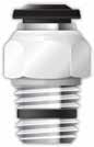
88020 STRAIGHT MALE
Part No. TubeA BL1L2CH1CH2 87210-02-021/81/8 .217(5,5)1.299(33).787(20).354(9).512(13) 87210-02-041/81/4 .276(7)1.299(33)1.003(25,5).354(9).591(15) 87210-53-02 5/32 (4) 1/8 .217(5,5)1.339(34).787(20).354(9).512(13) 87210-53-04 5/32 (4) 1/4 .276(7)1.299(33)1.003(25,5).354(9).591(15) 87210-04-021/41/8 .217(5,5)1.692(43).925(23,5).433(11).512(13) 87210-04-041/41/4 .276(7)1.692(43)1.062(27).433(11).591(15) 87210-04-061/43/8 .295(7,5)2.087(53)1.102(28).630(16).669(17) 87210-06-023/81/8 .217(5,5)2.047(52)1.082(27,5).630(16).590(15) 87210-06-043/81/4 .275(7)2.087(53)1.181(30).630(16).511(13) 87210-06-063/83/8 .295(7,5)2.087(53)1.181(30).630(16).669(17) 87210-06-083/81/2 .354(9)2.087(53)1.299(33).630(16).827(21) 87210-08-041/21/4 .276(7)2.402(61)1.240(31,5).748(19).591(15) 87210-08-061/23/8 .295(7,5)2.402(61)1.299(33).748(19).669(17) 87210-08-081/21/2 .354(9)2.402(61)1.417(36).748(19).827(21) CH2 CH1 L2 B A L1 Part No. TubeA BL1L2CH1CH2 87222-02-021/81/8 .269(6,5).669(17).807(20,5).354(9).512(13) 87222-02-041/81/4 .511(13).669(17).945(24).354(9).591(15) 87222-53-02 5/32 (4) 1/8 .269(6,5).669(17).787(20).354(9).512(13) 87222-53-04 5/32 (4) 1/4 .511(13).669(17).945(24).354(9).591(15) 87222-04-021/41/8 .269(6,5).827(21).866(22).433(11).512(13) 87222-04-041/41/4 .511(13).827(21).984(25).433(11).591(15) 87222-04-061/43/8 .511(13).827(21)1.102(28).433(11).591(15) 87222-06-023/81/8 .269(6,5)1.043(26,5)1.102(28).433(11).512(13) 87222-06-043/81/4 .511(13)1.043(26,5)1.102(28).630(16).591(15) 87222-06-063/83/8 .511(13)1.043(26,5)1.181(30).630(16).669(17) 87222-06-083/81/2 .669(17)1.043(26,5)1.299(33).630(16).827(21) 87222-08-041/21/4 .511(13)1.201(30,5)1.240(31,5).748(19).591(15) 87222-08-061/23/8 .511(13)1.201(30,5)1.299(33).748(19).669(17) 87222-08-081/21/2 .669(17)1.201(30,5)1.417(36).748(19).827(21) CH1 CH2 A L1 L2 L1 B Part No. TubeA BCLCH1CH2 88020-02-321/810/32 .157(4).310(8).787(18).315(8).079(2) 88020-53-32 5/32 (4) 10/32 .157(4).310(8).827(21).394(10).079(2) 88020-04-321/410/32 .157(4).390(10).925(23,5).512(13).079(2) UNF CH2 B CH1 A C L Part Number TubeA BCLCH 87010-02-321/810/32 .157(4).315(8).709(18).098(2,5) 87010-53-32 5/32 (4) 10/32 .157(4).394(10).787(20).098(2,5) 87010-04-321/410/32 .157(4).473(12).925(23,5).098(2,5) UNF C A CH L B Page 38
88115
SWIVEL ELBOW
UNF
88215
SWIVEL BRANCH TEE
88225
SWIVEL RUN TEE
L2
B
UNF CH1 L1 D A
UNF D A B L2 L1 L1 CH1 CH2
88007
STRAIGHT MALE
88117
SWIVEL ELBOW


Part No. TubeA
BL1L2CH1CH2D 88115-02-321/810/32 .157(4).650(16,5).689(17,5).354(9).315(8).393(10)
88115-53-32 5/32 (4) 10/32 .157(4).709(18).689(17,5).354(9).315(8).393(10)
88115-04-321/410/32 .157(4).846(21,5).768(19,5).433(11).433(11).492(12.5)
Part No. TubeA
BL1L2CH1CH2D
88215-02-321/810/32 .157(4)1.299(33).689(17,5).354(9).315(8).393(10)
88215-53-32 5/32 (4) 10/32 .157(4)1.299(33).708(18).354(9).315(8).393(10)
Part No. TubeA
BL1L2CH1CH2D
88225-02-321/810/32 .157(4).649(16,5).689(17,5).354(9).315(8).393(10)
88225-53-32 5/32 (4) 10/32 .157(4).699(17).708(18).354(9).315(8).393(10) 88225-04-321/410/32 .157(4).827(21).787(20).433(11).433(11).492(12.5)
Part No. TubeA
88007-04-021/41/8 .276(7).886(22,5).512(13).157(4)
88007-04-041/41/4 .413(10,5).965(24,5).551(14).157(4)
Part No. TubeA
88117-53-025/32(4)1/8 .276(7).708(18).768(19,5).354(9).512(13)
88117-53-045/32(4)1/4 .413(10,5).708(18).905(23).354(9).591(15)
88117-04-021/41/8 .276(7).827(21).846(21,5).433(11).512(13)
B L1 L2 CH2 CH1 A Page 39
88117-04-041/41/4 .413(10,5).827(21).984(25).433(11).591(15)
3.7 87 - 88 Serie s
A D
CH1 CH2 B L2
L1
88215-04-321/410/32 .157(4)1.692(43).768(19,5).433(11).433(11).492(12.5) CH2
BLCH1CH2 88007-53-025/32(4)1/8
.276(7).768(19,5).433(11).118(3) 88007-53-045/32(4)1/4 .413(10,5).886(22,5).551(14).118(3)
A B L CH1 CH2
PTF
BL1L2CH1CH2
PTF
88000
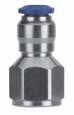
88030
STRAIGHT FEMALE
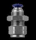
88055
FEMALE BULKHEAD CONNECTOR
88100
FIXED ELBOW
3.8 87 - 88 Serie s
STRAIGHT MALE
Part No. TubeA BLCH1CH2 88000-02-021/81/8 .355(9).768(19,5).433(11).079(2) 88000-02-041/81/4 .512(13).965(24,5).551(14).079(2) 88000-53-02 5/32 (4) 1/8 .355(9).826(21).433(11).118(3) 88000-53-04 5/32 (4) 1/4 .512(13).984(25).551(14).118(3) 88000-04-021/41/8 .355(9)1.023(25,5).512(13).157(4) 88000-04-041/41/4 .512(13)1.062(27).551(14).157(4) 88000-04-061/43/8 .512(13)1.141(29).709(18).157(4) 88000-05-02 5/16 (8) 1/8 .355(9)1.062(27).551(14).197(5) 88000-05-04 5/16 (8) 1/4 .512(13)1.082(27,5).551(14).236(6) 88000-05-06 5/16 (8) 3/8 .512(13)1.082(27,5).709(18).236(6) 88000-06-023/81/8 .355(9)1.259(32).669(17).197(5) 88000-06-043/81/4 .512(13)1.319(33,5).669(17).276(7) 88000-06-063/83/8 .512(13)1.319(33,5).709(18).276(7) 88000-06-083/81/2 .669(17)1.319(33,5).866(22).276(7) 88000-08-041/21/4 .512(13)1.535(39).787(20).197(5) 88000-08-061/23/8 .512(13)1.417(36).787(20).354(9) 88000-08-081/21/2 .669(17)1.575(40).866(22).394(10) NPTF CH2 CH1 A L B Part No. TubeA BLCH 88030-02-021/81/8 .374(9,5).945(21).512(13) 88030-02-041/81/4 .531(13,5).1.142(29).630(16) 88030-53-02 5/32 (4) 1/8 .374(9,5).984(25).512(13) 88030-53-04 5/32 (4) 1/4 .531(13,5)1.181(30).630(16) 88030-04-021/41/8 .374(9,5)1.024(26).512(13) 88030-04-041/41/4 .512(13)1.161(29,5).630(16) 88030-06-043/81/4 .531(13,5)1.279(32,5).709(18) 88030-06-063/83/8 .531(13,5)1.279(32,5).787(20) NPTF CH A B L NPTF Part No. TubeA BMSmaxCH1CH2CDL 88055-53-02 5/32 (4) 1/8 .374(9,5)M12X1.275(7).591(15).669(17).394(10).748(19)1.141(29) 88055-53-04 5/32 (4) 1/4 .531(13,5)M12X1.275(7).630(16).669(17).591(15).748(19)1.339(34) 88055-04-021/41/8 .374(9,5)M14X1.315(8).630(16).669(17).394(10).826(21)1.221(31) 88055-04-041/41/4 .531(13,5)M14X1.315(8).630(16).669(17).591(15).826(21)1.417(36) 88055-04-061/43/8 .531(13,5)M14X1.315(8).787(20).669(17).591(15).826(21)1.417(36) 88055-05-02 5/16 (8) 1/8 .374(9,5)M16X1.315(8).709(18).748(19).394(10).866(22)1.260(32) 88055-05-04 5/16 (8) 1/4 .531(13,5)M16X1.315(8).709(18).748(19).472(12).866(22)1.339(34) 88055-05-06 5/16 (8) 3/8 .531(13,5)M16X1.315(8).787(20).748(19).591(15).866(22)1.457(37) 88055-06-063/83/8 .531(13,5)M20X1.374(9.5).945(24).945(24).551(14)1.003(25.5)1.557(39,5) 88055-08-061/23/8 .531(13,5)M22X1.413(10,5).945(24)1.024(26).591(15)1.083(27.5)1.673(42.5) 88055-08-081/21/2 .690(17,5)M22X1.413(10,5).945(24)1.024(26).787(20)1.083(27.5)1.870(47,5) M CH2 L D S max C CH1 A B Part No. TubeA BL1L2CH1 88100-04-021/41/8 .335(8,5).846(21,5).728(18,5).433(11) 88100-04-041/41/4 .512(13).846(21,5).905(23).433(11) 88100-06-043/81/4 .512(13)1.062(27)1.043(26,5).630(16) 88100-06-063/83/8 .512(13)1.062(27)1.004(25,5).688(17) NPTF CH L1 A B L2 Page 40
88105
FEMALE ELBOW
88110
SWIVEL ELBOW
88210
SWIVEL BRANCH TEE
88222
SWIVEL RUN TEE
NPTF B L2
Part No. TubeA BL1L2CH1CH2 88105-53-02 5/32 (4) 1/8 .374(9,5).669(17).984(25).354(9).511(13)
88105-53-04 5/32 (4) 1/4 .531(13,5).669(17)1.240(31,5).354(9).629(16)
88105-04-021/41/8 .374(9,5).846(21,5)1.062(27).433(11).511(13)
L1
88105-04-041/41/4 .531(13,5).826(21)1.279(32.5).433(11).629(16)
88105-06-023/81/8 .374(9,5)1.062(27)1.220(31).511(13).511(13)
Part No. TubeA
BL1L2CH1CH2
88110-02-021/81/8 .335(8,5).669(17).906(23).354(9).512(13)
88110-02-041/81/4 .512(13).669(17)1.122(28,5).354(9).591(15)
88110-53-02
1/8
88110-04-021/41/8
.335(8,5).669(17).906(23).354(9).512(13)
.512(13).669(17)1.181(30).354(9).591(15)
.512(13).827(21)1.220(31).433(11).591(15)
.512(13).827(21)1.280(32,5).433(11).709(18)
CH2 CH1 L1 A L2 B
NPTF
.512(13)1.102(28)1.337(35).630(16).591(15)
.512(13)1.023(26)1.358(34,5).630(16).709(18)
88110-08-061/23/8 .512(13)1.201(30,5)1.476(37,5).748(19).709(18)
NPTF CH2 CH1 L1 A L2 B Part No. TubeA BL1L2CH1CH2 88210-02-021/81/8
88210-02-041/81/4
.512(13)1.299(33)1.122(27).354(9).591(15)
88210-08-041/21/4 .512(13)2.402(61)1.555(39,5).748(19).591(15)
88210-08-061/23/8 .512(13)2.402(61)1.476(37,5).748(19).709(18)
88210-08-081/21/2 .669(17)2.402(61)1.732(44).748(19).866(22)
NPTF
88222-02-041/81/4 .511(13).669(17)1.181(30).354(9).591(15)
88222-53-02 5/32 (4) 1/8 .295(7,5).669(17).906(23).354(9).512(13)
88222-04-021/41/8 .295(7,5).827(21).984(25).433(11).512(13)
88222-04-041/41/4 .511(13).827(21)1.220(31).433(11).591(15)
88222-06-043/81/4 .511(13)1.043(26,5)1.339(34).630(16).591(15)
88222-06-063/83/8 .511(13)1.043(26,5)1.358(34,5).630(16).709(18)
88222-06-083/81/2 .669(17)1.043(26,5)1.614(41).630(16).866(22)
88222-08-041/21/4 .512(13)1.201(30,5)1.476(37,5).748(19).591(15)
88222-08-061/23/8 .511(13)1.201(30,5)1.476(37,5).748(19).709(18)
88222-08-081/21/2 .669(17)1.201(30,5)1.732(44).748(19).866(22)
CH1 CH2 L1 L1 L2 B A Page 41
3.9 87 - 88 Serie s
88105-06-023/81/4 .531(13,5)1.062(27)1.397(35,5).629(16).629(16) CH1 CH2 A
5/32 (4)
1/4
88110-04-041/41/4
88110-04-061/43/8
88110-05-02 5/16 (8) 1/8 .335(8,5).886(22,5)1.043(26,5).512(13).512(13) 88110-05-04 5/16 (8) 1/4 .512(13).886(22,5)1.260(32).512(13).591(15) 88110-05-06 5/16 (8) 3/8 .512(13).886(22,5)1.280(32,5).512(13).709(18) 88110-06-023/81/8 .335(8,5)1.043(26,5)1.181(30).630(16).512(13) 88110-06-043/81/4
88110-06-063/83/8
88110-53-04
5/32 (4)
.335(8,5).827(21)1.023(26).433(11).512(13)
88110-06-083/81/2 .669(17)1.043(26,5)1.614(41).630(16).866(22)
88110-08-041/21/4 .512(13)1.201(30,5)1.555(39,5).748(19).591(15)
88210-53-02 5/32 (4) 1/8 .295(7.5)1.299(33).906(23).354(9).512(13) 88210-53-04 5/32 (4) 1/4 .512(13)1.299(33)1.181(30).354(9).591(15) 88210-04-021/41/8 .295(7.5)1.654(42)1.023(26).433(11).512(13) 88210-04-041/41/4
88210-06-043/81/4
88210-06-063/83/8
88210-06-083/81/2
88110-08-081/21/2 .669(17)1.201(30,5)1.732(44).748(19).866(22)
.295(7,5)1.299(33).906(23).354(9).512(13)
.512(13)1.654(42)1.220(31).433(11).591(15)
.512(13)2.087(53)1.337(35).630(16).591(15)
.512(13)2.087(53)1.358(34,5).630(16).709(18)
.669(17)2.087(53)1.614(41).630(16).866(22)
Part No. TubeA BL1L2CH1CH2
88222-02-021/81/8 .295(7,5).669(17).906(23).354(9).512(13)
3.10 87 - 88 Serie s 88040 UNION 88050 BULKHEAD UNION 88130 UNION ELBOW 88230 UNION TEE 88310 UNION Y Part No. TubeTube BL 88040-021/8 .335(8.5)1.024(26) 88040-53 5/32 (4) .413(10,5)1.181(30) 88040-04-531/4 5/32 (4) .492(12,5)1.279(32,5) 88040-041/4 .492(12,5)1.378(35) 88040-05 5/16 (8) .571(14,5)1.465(37) 88040-06-043/81/4 .688(17,5)1.555(39,5) 88040-063/8 .688(17,5)1.693(43) 88040-06-083/81/2 .807(20,5)1.850(47) 88040-081/2 .807(20,5)1.909(48,5) L B Part No. TubeM LCHAmax 88050-021/8M10X1 1.024(26).551(14).197(5) 88050-53 5/32 (4) M12X1 1.220(32).669(17).276(7) 88050-041/4M14X1 1.378(35).669(17).374(9,5) 88050-05 5/16 (8) M16X1 1.476(37,5).748(19).413(10,5) 88050-063/8M20X1 1.732(44).945(24).492(12,5) 88050-081/2M22X1 1.929(49)1.024(26).650(16,5) CH A max L M Part No. Tube LCH 88130-021/8 .669(17).354(9) 88130-53 5/32 (4) .669(17).354(9) 88130-041/4 .827(21).433(11) 88130-05 5/16 (8) .905(23).512(13) 88130-063/8 1.043(26,5).630(16) 88130-081/2 1.201(30,5).748(19) CH L L Part No. Tube L1L2CH 88230-021/8 1.299(33).669(17).354(9) 88230-53 5/32 (4) 1.339(34).669(17).354(9) 88230-041/4 1.654(42).827(21).433(11) 88230-05 5/16 (8) 1.772(45).886(22,5).512(13) 88230-063/8 2.087(53)1.043(26,5).630(16) 88230-081/2 2.402(61)1.201(30,5).748(19) CH L1 L2 Part No. Tube ALCH 88310-021/8 .394(10)1.142(29).433(11) 88310-53 5/32 (4) .433(11)1.260(32).433(11) 88310-041/4 .531(13,5)1.437(36,5).511(13) 88310-05 5/16 (8) .610(15,5)1.514(41).511(13) 88310-063/8 .728(18.5)1.890(48).708(18) CH L A Page 42

3.11 87 - 88 Serie s 88500 SINGLE BANJO BODY 88510 DOUBLE BANJO BODY 88610B NYLON PLUG 88700 TUBE REDUCER 50980 SECURITY CLIP Part No. TubeA BLCH 88500-02-021/81/8 .591(15).767(19,5).551(14) 88500-53-32 5/32 (4) 10/32 .492(12,5).748(19)88500-53-02 5/32 (4) 1/8 .591(15).827(21).551(14) 88500-04-021/41/8 .669(17).885(22,5).551(14) 88500-04-041/41/4 .669(17).984(25).709(18) 88500-06-043/81/4 .787(20)1.142(29).709(18) 88500-06-063/83/8 .787(20)1.201(30,5).827(21) 88500-08-061/23/8 .787(20)1.259(32).827(21) 88500-08-081/21/2 .944(24)1.377(35).984(25) ForBANJOSTEMassembliessee10.7/10.8/10.9 L A CH B Part No. TubeA BLCH 88510-53-32 5/32 (4) 10/32 .492(12,5)1.496(38)88510-04-021/41/8 .591(15)1.732(44).551(14) 88510-04-041/41/4 .669(17)1.968(50).709(18) ForBANJOSTEMassembliessee10.7/10.8/10.9 CH L A B Part No. Tube L 88610B-021/8 .708(18) 88610B-53 5/32 (4) .925(23,5) 88610B-041/4 .964(24,5) 88610B-05 5/16 (8) 1.023(26) 88610B-063/8 1.122(28,5) 88610B-081/2 1.122(28,5) L Part No. AB L 88700-04-021/41/8 1.181(30) 88700-04-531/4 5/32 (4) 1.181(30) 88700-06-043/81/4 1.377(35) 88700-08-041/21/4 1.693(43) 88700-08-061/23/8 1.693(43) B A L Part No. Tube 50980-53 5/32 (4) 50980-04 1/4 (6) 50980-05 5/16 (8) 50980-06 3/8 (10) 50980-08 1/2 (12) Page 43
87800
PUSH-FIT CARTRIDGES
SEAT
55801
TOOL FOR PUSH-FIT CARTRIDGES SEAT
55802
TOOL FOR PUSH-FIT CARTRIDGES SEAT
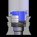
PUSH-FIT CARTRIDGE ASSEMBLING INSTRUCTIONS ART. 87800 1 2
Use tool to drill into material to create the seat for the Push-Fit Cartridge. Insert


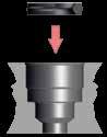
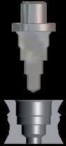
3.12 87 - 88 Serie s
lip seal.
3 4
Insert cartridge into the assembling tool.
Part No. Tube H1H2D 87800-021/8 .386(10).280(7).280(7) 87800-53 5/32 (4) .445(11.5).323(8).338(8.5) 87800-041/4 .520(13).374(9.5).413(10.5) 87800-05 5/16 (8) .508(13).374(9.5).492(12.5) 87800-063/8 .625(16).472(12).642(16) 87800-081/2 .713(18).543(14).740(19) D H1 H2 Tube D1D2D3D4H1H2H3R 1/8 (3) .134(3,4).238(6,05).252(6,4).274(6,95).146(3,7).240(6,1).339(8,6).020(0,5) 5/32 (4) .165(4,2).293(7,45).331(8,4).354(9).148(3,75).256(6,5).374(9,5).020(0,5) 1/4 (6.6) .259(6,6).368(9,35).411(10,45).447(11,35).197(5).335(8,5).453(11,5).020(0,5) 5/16 (8) .323(8,2).449(11,4).488(12,4).508(12,9).205(5,2).335(8,5).492(12,5).030(0,75) 3/8 (9.7) .381(9,7).571(14,5).606(15,4).630(16).264(6,7).413(10,5).591(15).030(0,75) 1/2 (13) .511(13).669(17).709(18).748(19).295(7,5).476(12,1).669(17).039(1) Seatsdimensionspush-fitcartridges. D4 ± 70° R. .0019 D3 + .0019 0 D2 + .0039 0 .0039 0 .0078 0 D1 + .0039 0 H1 ± .0019 H2 + H1 + Part No. Tube øBody 55801-3 1/8 (3) .394(10) 55801-4 5/32 (4) .394(10) 87801-041/4 .472(12) 55801-8 5/16 (8) .472(12) 87801-063/8 .630(16) 87801-081/2 .630(16) Part No. Tube 55802-021/8 55802-4 5/32 (4) 55802-6 1/4 (6) 55802-8 5/16 (8) 55802-10 3/8 (10) 55802-12 1/2 (12) Page 44
Press cartridge into the seat until it stops.

3.13 87 - 88 Serie s
FITTING KIT - 4MM TUBE
FITTING KIT - 4MM TUBE
FITTING KIT -
TUBE Part No. Description Qty 87000-02-02 StraightMale-1/8Tubex1/8Male5 87000-02-04 StraightMale-1/8Tubex1/4Male5 87000-04-02 StraightMale-1/4Tubex1/8Male5 87110-02-02 SwivelElbow-1/8Tubex1/8Male5 87110-02-04 SwivelElbow-1/8Tubex1/4Male5 87110-04-02 SwivelElbow-1/4Tubex1/8Male5 87210-02-02 SwivelBranchTee-1/8Tubex1/8Male5 87210-02-04 SwivelBranchTee-1/8Tubex1/4Male5 87210-04-02 SwivelBranchTee-1/4Tubex1/8Male5 88040-02 Union-1/8Tube5 88130-02 UnionElbow-1/8Tube5 88230-02 UnionTee-1/8Tube5 Part No. Description Qty 87000-04-02 StraightMale-1/4Tubex1/8Male5 87000-04-04 StraightMale-1/4Tubex1/4Male5 87000-04-06 StraightMale-1/4Tubex3/8Male5 87110-04-02 SwivelElbow-1/4Tubex1/8Male5 87110-04-04 SwivelElbow-1/4Tubex1/4Male5 87110-04-06 SwivelElbow-1/4Tubex3/8Male5 87210-04-02 SwivelBranchTee-1/4Tubex1/8Male5 87210-04-04 SwivelBranchTee-1/4Tubex1/4Male5 87210-04-06 SwivelBranchTee-1/4Tubex3/8Male5 88040-04 Union-1/4Tube5 88130-04 UnionElbow-1/4Tube5 88230-04 UnionTee-1/4Tube5 Part No. Description Qty 87000-06-04 StraightMale-3/8Tubex1/4Male5 87000-06-06 StraightMale-3/8Tubex3/8Male5 87000-06-08 StraightMale-3/8Tubex1/2Male5 87110-06-04 SwivelElbow-3/8Tubex1/4Male5 87110-06-06 SwivelElbow-3/8Tubex3/8Male5 87110-06-08 SwivelElbow-3/8Tubex1/2Male5 87210-06-04 SwivelBranchTee-3/8Tubex1/4Male5 87210-06-06 SwivelBranchTee-3/8Tubex3/8Male5 87210-06-08 SwivelBranchTee-3/8Tubex1/2Male5 88040-06 Union-3/8Tube5 88130-06 UnionElbow-3/8Tube5 88230-06 UnionTee-3/8Tube5 Page 45
FITTING KITS 87861-02
87861-04
87861-06
4MM
3.14 87 - 88 Serie s
KIT - 4MM TUBE
KIT - 4MM TUBE Part No. Description Qty 87000-08-04 StraightMale-1/2Tubex1/4Male5 87000-08-06 StraightMale-1/2Tubex3/8Male5 87000-08-08 StraightMale-1/2Tubex1/2Male5 87110-08-04 SwivelElbow-1/2Tubex1/4Male5 87110-08-06 SwivelElbow-1/2Tubex3/8Male5 87110-08-08 SwivelElbow-1/2Tubex1/2Male5 87210-08-04 SwivelBranchTee-1/2Tubex1/4Male5 87210-08-06 SwivelBranchTee-1/2Tubex3/8Male5 87210-08-08 SwivelBranchTee-1/2Tubex1/2Male5 88040-08 Union-1/2Tube5 88130-08 UnionElbow-1/2Tube5 88230-08 UnionTee-1/2Tube5 Part No. Description Qty 87000-04-04 StraightMale-1/4Tubex1/4Male5 87000-06-06 StraightMale-3/8Tubex3/8Male5 87000-08-08 StraightMale-1/2Tubex1/2Male5 87110-04-04 SwivelElbow-1/4Tubex1/4Male5 87110-06-06 SwivelElbow-3/8Tubex3/8Male5 87110-08-08 SwivelElbow-1/2Tubex1/2Male5 87210-04-04 SwivelBranchTee-1/4Tubex1/4Male5 87210-06-06 SwivelBranchTee-3/8Tubex3/8Male5 87210-08-08 SwivelBranchTee-1/2Tubex1/2Male5 88040-04 Union-1/4Tube5 88040-06 Union-3/8Tube5 88040-08 Union-1/2Tube5 88130-04 UnionElbow-1/4Tube5 88130-06 UnionElbow-3/8Tube5 88130-08 UnionElbow-1/2Tube5 88230-04 UnionTee-1/4Tube5 88230-06 UnionTee-3/8Tube5 88230-08 UnionTee-1/2Tube5 Page 46
87861-08 FITTING
87861-90 FITTING
50N Series


Fitting Kits
Aignep reserves the right to vary models and dimensions without notice
50000N Pg.4.5 50130N Pg.4.10 50105N Pg.4.7 50900N Pg.4.13 50861N-4 Pg.4.15 50861N-12 Pg.4.16 50861N-8 Pg.4.15 50861N-6 Pg.4.15 50861N-10 Pg.4.16 50010N Pg.4.5 50230N Pg.4.11 50115N Pg.4.8 55800N Pg.4.13 50110N Pg.4.5 50125N Pg.4.8 55801 Pg.4.13 50310N Pg.4.11 50120N Pg.4.5 50500N Pg.4.11 50215N Pg.4.8 55802 Pg.4.13 50210N Pg.4.6 50510N Pg.4.11 50225N Pg.4.9 50980 Pg.4.14 50222N Pg.4.6 50600 Pg.4.12 50100N Pg.4.9 50991 Pg.4.14 50020N Pg.4.7 50625 Pg.4.12 50040N Pg.4.10 50010N Pg.4.6 50610 Pg.4.12 50200N Pg.4.9 50006 Pg.4.14 50030N Pg.4.7 50700N Pg.4.12 50050N Pg.4.10 50055N Pg.4.10 50465N Pg.4.10 50326N Pg.4.9 Page 47
PUSH-TO-CONNECT FITTINGS FOR METRIC TUBE
50N Series
50000N Page 48
Reference Standard
TECHNICAL CHARACTERISTICS
Bar
Pressure Rating
Vacuum ~ 290 PSI
-0.99 bar ~ 20 bar
-0.099 MPa ~ 2.0 MPa
Media
• Compressed Air
• Vacuum Water Steam (FKM required)
Advantages
1 The 303 Stainless Steel gripper ensures a tight clamp for tubes of any material without damaging the tube’s surface. The secure connection between the tube and the fitting will hold up to severe conditions such as impact and vibrations.
2 The shape of the safety ring and the molded seal perfectly seal off the tube, creating a vacuum.
3 Series with several types of threads: SWIFTFIT BSPP BSPT
4 All straight fittings can be tightened with an Allen wrench because of our internal hex design. This enables the end user to tighten the fitting in spaces too small for an openend wrench.
5 Our rotating Swivel Elbow fittings are equipped with a safety ring that enables the fitting to rotate without losing a tight seal.
Component Parts and Materials
1 Composite Release Collet
2 Nickel Plated Brass Body
3 NBR Thread Seal
4 Nickel Plated Brass Sleeve
5 303 Stainless Steel Gripper
6 Technopolymer Safety Ring
7 NBR Molded Seal
8 Safety Ring
9 NBR Seal
10 Nickel Plated Thread Brass Body
Tubing Compatibility
Nylon 6 - 11 -12
Polyethylene Polyurethane (“98 Shore A for best result)
PTFE FEP

4.3 50 N Serie s
1907/2006 2011/65/CE PED 2014/68/UE ISO 14743:2004 SILICON FREE
NBR -4º F ~ 176º F -20º C ~ 80º C Temperatures Rating Applications Pneumatic Automation
Automotive
Textile, Packaging Compressed Air Circuit • Vacuum 1 2 3 4 5 6 7 9 10 8 1 3 4 5 2 Page 49
•
•
THREADS & ADVANTAGES
One fitting... Endless possibilities
The SWIFTFIT Universal Thread has been designed to offer the following advantages to the end users:
• Reduced overall length
• Smaller hex dimensions compared to parallel threads
• Fits with various parallel and tapered threads
• All SWIFTFIT fittings have been equipped with threads and an NBR thread seal that will universally connect to all thread types.
Our SWIFTFIT universal fittings also work on non-flat surfaces without compromising an air-tight seal.
BSPP Threads
The BSPP Thread has been designed to offer the following advantages to the end users:
• Standard ISO 228 and ISO R/262
• Designed for use in BSPP connections with an integrated NBR o-ring that provides a perfect seal
• Completely reusable
BSPT Thread with seal
The BSPT Thread has been designed to offer the following advantages to the end users:
• Standard ISO 7.1, BS 21, DN 2999
• Designed for use in BSPT and BSPP connections with an integrated NBR thread seal that provides an additional seal
4.4 50 N Serie s NPT NPTF Tapered ISO 228 BSP PF Parallell ISO 7 BSPT PT Tapered ISO 7 BSPP Parallell
Torque Specifications Recommended Torque Thread Size Min. Breaking torque M5 0.8 Nm 3.2 Nm M8 3 Nm 8 Nm 1/2 3 Nm 8 Nm 1/4 9 Nm 30 Nm 3/8 10 Nm 60 Nm 1/2 12 Nm 50 Nm Torque Specifications Recommended Torque Thread Size Min. Max. 1/8 5 Nm 7 Nm 1/4 5 Nm 7 Nm 3/8 5 Nm 7 Nm 1/2 5 Nm 7 Nm Torque Specifications Recommended Torque Thread Size Min. Max. 1/8 5 Nm 7 Nm 1/4 5 Nm 7 Nm 3/8 5 Nm 7 Nm 1/2 5 Nm 7 Nm Inclined Concave Convex Page 50
50000N
STRAIGHT MALE
50010N
STRAIGHT MALE WITH INTERNAL HEX
50110N
SWIVEL ELBOW

.354(9).885(22,5)1.003(25,5).472(12).826(21).571(14,5)
.275(7)1.043(26,5)1.043(26,5).551(14).629(16).689(17,5) 50110N-10-3/8103/8 .295(7.5)1.043(26,5).946(24,5).551(14).669(17).689(17,5)
50110N-10-1/2101/2 .354(9)1.043(26,5)1.062(27).551(14).826(21).689(17,5)
50110N-12-3/8123/8 .295(7.5)1.240(31,5)1.043(26,5).629(16).787(20).846(21,5)
50110N-12-1/2121/2 .354(9)1.240(31,5)1.141(29).629(16).826(21).846(21,5)
50110N-14-3/8143/8 .295(7.5)1.240(31,5)1.062(27).629(16).787(20).846(21,5)
50110N-14-1/2141/2 .354(9)1.240(31,5)1.161(29,5).629(16).826(21).846(21,5)
50120N
SWIVEL MALE EXTENDED ELBOW
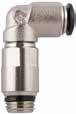


.276(7).709(18)1.299(33).354(9).591(15).394(10)
50120N-5-1/851/8 .217(5,5).787(20)1.417(36).433(11).472(12).492(12,5)
.217(5,5).827(21)1.417(36).433(11).472(12).492(12,5) 50120N-6-1/461/4 .276(7).827(21)1.476(37,5).433(11).591(15).492(12,5)
4.5 50 N Serie s
Part No. TubeA BLCH1CH2 50000N-4-1/8 5/32 (4) 1/8 .217(5,5).709(18).433(11).118(3) 50000N-4-1/4 5/32 (4) 1/4 .276(7).748(19).551(14).118(3) 50000N-5-1/851/8 .217(5,5).787(20).433(11).157(4) 50000N-5-1/451/4 .276(7).787(20).551(14).157(4) 50000N-6-1/861/8 .217(5,5).846(21,5).512(13).157(4) 50000N-6-1/461/4 .276(7).827(21).551(14).157(4) 50000N-6-3/863/8 .295(7,5).906(23).669(17).157(4) 50000N-6-1/261/2 .354(9).925(23,5).827(21).157(4) 50000N-8-1/8 5/16 (8) 1/8 .217(5,5).965(24,5).551(14).197(5) 50000N-8-1/4 5/16 (8) 1/4 .276(7).866(22).551(14).236(6) 50000N-8-3/8 5/16 (8) 3/8 .295(7,5).906(23).669(17).236(6) 50000N-8-1/2 5/16 (8) 1/2 .354(9).925(23,5).827(21).236(6) 50000N-10-1/4101/4 .276(7)1.102(28).669(17).276(7) 50000N-10-3/8103/8 .295(7,5)1.004(25,5).669(17).315(8) 50000N-10-1/2101/2 .354(9)1.024(26).827(21).315(8) 50000N-12-1/4121/4 .276(7)1.240(31,5).787(20).276(7) 50000N-12-3/8123/8 .295(7,5)1.161(29,5).787(20).354(9) 50000N-12-1/2121/2 .354(9)1.240(31,5).827(21).394(10) 50000N-14-3/8143/8 .295(7,5)1.280(32,5).827(21).354(9) 50000N-14-1/2141/2 .354(9)1.240(31,5).827(21).394(10) CH1 CH2 B L A Part No. TubeA BCLCH 50010N-4-1/8 5/32 (4) 1/8 .217(5,5).433(11).709(18).118(3) 50010N-6-1/861/8 .217(5,5).472(12).867(21,5).157(4) 50010N-6-1/461/4 .276(7).551(14).827(21).157(4) 50010N-8-1/8 5/16 (8) 1/8 .217(5,5).551(14).984(25).196(5) 50010N-8-1/4 5/16 (8) 1/4 .276(7).551(14).886(22,5).236(6) A C L B CH Part No. TubeA BL1L2CH1CH2 D 50110N-4-1/8 5/32 (4) 1/8 .216(5.5).708(18).767(19,5).354(9).512(13).394(10) 50110N-4-1/4 5/32 (4) 1/4 .275(7).748(19).826(21).354(9).590(15).394(10) 50110N-5-1/851/8 .216(5.5).788(20).846(21,5).433(11).512(13).492(12,5) 50110N-6-1/861/8 .216(5.5).826(21).846(21,5).433(11).512(13).492(12,5) 50110N-6-1/461/4 .275(7).826(21).905(23).433(11).590(15).492(12,5) 50110N-8-1/8 5/16 (8) 1/8 .216(5.5).885(22,5).885(22,5).472(12).512(13).571(14,5) 50110N-8-1/4 5/16 (8) 1/4 .275(7).885(22,5).885(22,5).472(12).590(15).571(14,5) 50110N-8-3/8 5/16 (8) 3/8 .295(7.5).885(22,5).905(23).472(12).669(17).571(14,5) 50110N-8-1/2 5/16 (8) 1/2
50110N-10-1/4101/4
B D L1 L2 CH2 CH1 A Part No. TubeA BL1L2CH1CH2 D 50120N-4-1/8 5/32 (4) 1/8
5/32 (4) 1/4
.217(5,5).709(18)1.240(31,5).354(9).472(12).394(10) 50120N-4-1/4
50120N-8-1/8 5/16 (8) 1/8 .197(5).898(22,5)1.595(40,5).472(12).472(12).571(14,5) 50120N-8-1/4 5/16 (8) 1/4 .276(7).886(22,5)1.595(40,5).472(12).591(15).571(14,5) 50120N-8-3/8 5/16 (8) 3/8 .296(7,5).886(22,5)1.614(41).472(12).630(16).571(14,5) 50120N-10-1/4101/4 .276(7)1.043(26,5)1.811(46).551(14).591(15).689(17,5) 50120N-10-3/8103/8 .296(7,5)1.043(26,5)1.733(44).551(14).670(17).689(17,5) A D CH2 B L2 CH1 L1 Page 51
50120N-6-1/861/8
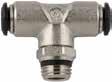
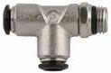

4.6 50 N Serie s
SWIVEL BRANCH TEE
SWIVEL RUN TEE
MALE WITH INTERNAL HEX Part No. TubeA BL1L2CH1CH2 D 50210N-4-1/8 5/32 (4) 1/8 .216(5,5)1.338(34).787(20).354(9).511(13).394(10) 50210N-4-1/4 5/32 (4) 1/4 .275(7)1.338(34).846(21,5).354(9).590(15).394(10) 50210N-5-1/851/8 .216(5,5)1.575(40).866(22).433(11).511(13).492(12,5) 50210N-6-1/861/8 .216(5,5)1.653(42).866(22).433(11).511(13).492(12,5) 50210N-6-1/461/4 .275(7)1.653(42).925(23,5).433(11).590(15).492(12,5) 50210N-8-1/8 5/16 (8) 1/8 .216(5,5)1.771(45)1.003(25,5).511(13).511(13).571(14,5) 50210N-8-1/4 5/16 (8) 1/4 .275(7)1.771(45)1.003(25,5).511(13).590(15).571(14,5) 50210N-8-3/8 5/16 (8) 3/8 .295(7,5)1.771(45)1.023(26).511(13).669(17).571(14,5) 50210N-8-1/2 5/16 (8) 1/2 .354(9)1.771(45)1.122(28,5).511(13).826(21).571(14,5) 50210N-10-1/4101/4 .275(7)2.086(53)1.141(29).551(14).629(16).689(17,5) 50210N-10-3/8103/8 .295(7,5)2.086(53)1.062(27).551(14).669(17).689(17,5) 50210N-10-1/2101/2 .354(9)2.086(53)1.161(29,5).551(14).826(21).689(17,5) 50210N-12-3/8123/8 .295(7,5)2.460(62,5)1.161(29,5).629(16).787(20).846(21,5) 50210N-12-1/2121/2 .354(9)2.460(62,5)1.259(32).629(16).826(21).846(21,5) 50210N-14-3/8143/8 .295(7,5)2.460(62,5)1.161(29,5).629(16).787(20).846(21,5) 50210N-14-1/2141/2 .354(9)2.460(62,5)1.259(32).629(16).826(21).846(21,5) CH1 D L1 A CH2 B L2 Part No. TubeA BL1L2CH1CH2D 50222N-4-1/8 5/32 (4) 1/8 .216(5,5).669(17).787(20).354(9).511(13).394(10) 50222N-4-1/4 5/32 (4) 1/4 .275(7).669(17).846(21,5).354(9).590(15).394(10) 50222N-5-1/851/8 .216(5,5).788(20).866(22).433(11).511(13).492(12,5) 50222N-6-1/861/8 .216(5,5).826(21).866(22).433(11).511(13).492(12,5) 50222N-6-1/461/4 .275(7).826(21).925(23,5).433(11).590(15).492(12,5) 50222N-8-1/8 5/16 (8) 1/8 .216(5,5).885(22,5).944(24).511(13).511(13).571(14,5) 50222N-8-1/4 5/16 (8) 1/4 .275(7).885(22,5).944(24).511(13).590(15).571(14,5) 50222N-8-3/8 5/16 (8) 3/8 .295(7,5).885(22,5)1.062(27).511(13).669(17).571(14,5) 50222N-8-1/2 5/16 (8) 1/2 .354(9).885(22,5)1.062(27).511(13).826(21).571(14,5) 50222N-10-1/4101/4 .275(7)1.043(26,5)1.023(26).551(14).629(16).689(17,5) 50222N-10-3/8103/8 .295(7,5)1.043(26,5)1.023(26).551(14).669(17).689(17,5) 50222N-10-1/2101/2 .354(9)1.043(26,5)1.122(28,5).551(14).826(21).689(17,5) 50222N-12-3/8123/8 .295(7,5)1.240(31,5)1.161(29,5).629(16).787(20).847(21,5) 50222N-12-1/2121/2 .354(9)1.240(31,5)1.259(32).629(16).826(21).847(21,5) L1 L1 L2 B A D CH1 CH2 Part No. TubeA BCLCH 50010N-3-M53M5 .157(4).315(8).748(19).098(2,5) 50010N-4-M5 5/32 (4) M5 .157(4).394(10).768(19,5).098(2,5) 50010N-4-M7x1 5/32 (4) M7x1 .197(5).394(10).827(21).098(2,5) 50010N-6-M56M5 .157(4).472(12).965(24,5).098(2,5) 50010N-6-M6x16M6x1 .197(5).472(12).944(24).098(2,5) BSPP C A CH L B Page 52
50210N
50222N
50010N STRAIGHT
.212(5,4).512(13).866(22).472(12).157(4)
50020N-5-1/451/4 .279(7,1).630(16).866(22).472(12).157(4)
50020N-6-M56M5 .141(3,6).394(10).965(24,5).512(13).079(2)
50020N-6-1/861/8 .212(5,4).512(13).925(23,5).512(13).157(4)
50020N-6-1/461/4 .279(7,1).630(16).925(23,5).512(13).157(4)
50020N-6-3/863/8 .318(8,1).787(20).984(25).512(13).157(4)
50020N-6-1/261/2 .377(9,6).984(25)1.063(27).512(13).157(4)
.318(8,1).787(20)1.083(27,5).669(17).315(8) 50020N-10-1/2101/2 .377(9,6).984(25)1.063(27).669(17).315(8)
50020N-12-1/4121/4 .279(7,1).630(16)1.358(34,5).787(20).236(6)
50020N-12-3/8123/8 .318(8,1).787(20)1.339(34).787(20).315(8)
50020N-12-1/2121/2 .377(9,6).984(25)1.220(31).866(22).394(10)
50020N-14-3/8143/8 .318(8,1).787(20)1.378(35).827(21).394(10)
50020N-14-1/2141/2 .377(9,6).984(25)1,260(32).866(22).394(10)
50020N-6-M8X16M8x1 .212(5,4).472(12).965(24,5).512(13).118(3)


50020N-6-M10X16M10x1 .212(5,4).512(13).905(23).512(13).157(4)
50020N-6-M12X16M12X1 .287(7,3).591(15).925(23,5).512(13).157(4)
50020N-6-M12X1,25 6M12X1,25 .287(7,3).591(15).925(23,5).512(13).157(4)
50020N-6-M12X1,5 6M12X1,5 .287(7,3).591(15).925(23,5).512(13).157(4)
50020N-8-M8x18M8x1 .212(5,4).472(12)1.004(25,5).551(14).157(4)
50020N-8-M10x18M10x1 .212(5,4).512(13)1.004(25,5).551(14).157(4)
.472(12).885(22,5).905(23).472(12).512(13).571(14,5) 50105N-10-1/4101/4 .433(11)1.043(26,5).984(25).551(14).748(19).669(17) 50105N-10-3/8103/8 .472(12)1.043(26,5)1.102(28).551(14).748(19).669(17)
.590(15)1.240(31,5)1.358(34,5).630(16).944(24).787(20)
4.7 50 N Serie s 50020N STRAIGHT MALE 50030N STRAIGHT FEMALE 50105N FEMALE ELBOW Part No. TubeA BCLCH1CH2 50020N-3-M53M5 .141(3,6).315(8).748(19).315(8).079(2) 50020N-4-M3 5/32 (4) M3 .118(3).394(10).827(21)-.315(8) 50020N-4-M5 5/32 (4) M5 .141(3,6).315(8).827(21).394(10).079(2) 50020N-4-1/8 5/32 (4) 1/8 .212(5,4).512(13).787(20).394(10).118(3) 50020N-4-1/4 5/32 (4) 1/4 .279(7,1).630(16).768(19,5).630(16).118(3) 50020N-4-3/8 5/32 (4) 3/8 .318(8,1).787(20).708(18).787(20).118(3) 50020N-5-M55M5 .141(3,6).315(8).925(23,5).472(12).079(2) 50020N-5-1/851/8
5/16 (8) 1/8 .279(7,1).512(13).984(25).551(14).197(5) 50020N-8-1/4 5/16 (8) 1/4 .318(8,1).630(16).906(23).551(14).236(6) 50020N-8-3/8 5/16 (8) 3/8 .318(8,1).787(20).945(24).551(14).236(6) 50020N-8-1/2 5/16 (8) 1/2 .377(9,6).984(25)1.043(26,5).551(14).236(6) 50020N-10-1/4101/4 .279(7,1).630(16)1.201(30,5).669(17).236(6) 50020N-10-3/8103/8
50020N-8-1/8
50020N-8-M12X1,5 8M12X1,5 .287(7,3).591(15)1.083(27,5).551(14).236(6) BSPP CH2 B CH1 A C L Part No. TubeA BLCH 50030N-3-M53M5 .216(5,5).728(18,5).355(9) 50030N-4-M5 5/32 (4) M5 .216(5,5).826(21).433(11) 50030N-4-1/8 5/32 (4) 1/8 .334(8,5).944(24).511(13) 50030N-4-1/4 5/32 (4) 1/4 .433(11)1.082(27,5).629(16) 50030N-5-1/851/8 .334(8,5)1.043(26,5).511(13) 50030N-6-1/861/8 .334(8,5)1.023(26).511(13) 50030N-6-1/461/4 .433(11)1.161(29,5).629(16) 50030N-8-1/8 5/16 (8) 1/8 .334(8,5)1.062(27).590(15) 50030N-8-1/4 5/16 (8) 1/4 .433(11)1.161(29,5).669(17) 50030N-8-3/8 5/16 (8) 3/8 .472(12)1.259(32).748(19) 50030N-10-1/4101/4 .433(11)1.259(32).708(18) 50030N-10-3/8103/8 .472(12)1.318(33,5).748(19) 50030N-10-1/2101/2 .590(15)1.535(39).944(24) 50030N-12-3/8123/8 .472(12)1.417(36).826(21) 50030N-12-1/2121/2 .590(15)1.614(41).944(24) BSPP CH A B L B CH L A Part No. TubeA BL1L2CH1CH2D 50105N-4-1/8 5/32 (4) 1/8 .334(8,5).708(18).787(20).354(9).511(13).394(10) 50105N-4-1/4 5/32 (4) 1/4 .433(11).708(18).846(21,5).354(9).629(16).394(10) 50105N-6-1/861/8
50105N-6-1/461/4
50105N-8-1/8 5/16 (8) 1/8 .334(8,5).885(22,5).807(20,5).472(12).511(13).571(14,5)
5/16 (8) 1/4
50105N-8-3/8 5/16 (8) 3/8
50105N-12-1/2121/2
BSPP L1 D B A CH2 CH1 L2 Page 53
.334(8,5).826(21).807(20,5).433(11).511(13).492(12,5)
.433(11).826(21).905(23).433(11).629(16).492(12,5)
50105N-8-1/4
.433(11).885(22,5).905(23).472(12).629(16).571(14,5)

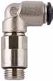
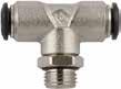
4.8 50 N Serie s 50115N
ELBOW 50125N
EXTENDED ELBOW 50215N SWIVEL BRANCH TEE Part No. TubeA BL1L2CH1CH2D 50115N-3-M53M5 .138(3,5).650(16,5).689(17,5).354(9).315(8).394(10) 50115N-4-M5 5/32 (4) M5 .138(3,5).709(18).689(17,5).354(9).315(8).394(10) 50115N-4-1/8 5/32 (4) 1/8 .217(5,5).709(18).709(18).354(9).512(13).394(10) 50115N-4-1/4 5/32 (4) 1/4 .276(7).709(18).709(18).354(9).63(16).394(10) 50115N-5-M55M5 .138(3,5).787(20).787(20).433(11).433(11).492(12,5) 50115N-5-1/851/8 .217(5,5).787(20).787(20).433(11).512(13).492(12,5) 50115N-6-M56M5 .138(3,5).827(21).787(20).433(11).433(11).492(12,5) 50115N-6-1/861/8 .217(5,5).827(21).787(20).433(11).512(13).492(12,5) 50115N-6-1/461/4 .276(7).827(21).846(21,5).433(11).63(16).492(12,5) 50115N-8-1/8 5/16 (8) 1/8 .217(5,5).886(22,5).827(21).472(12).512(13).571(14,5) 50115N-8-1/4 5/16 (8) 1/4 .276(7).886(22,5).846(21,5).472(12).63(16).571(14,5) 50115N-8-3/8 5/16 (8) 3/8 .315(8).886(22,5).925(23,5).472(12).787(20).571(14,5) 50115N-8-1/2 5/16 (8) 1/2 .374(9,5).886(22,5).984(25).472(12).984(25).571(14,5) 50115N-10-1/4101/4 .276(7)1.043(26,5)1.004(25,5).551(14).63(16).689(17,5) 50115N-10-3/8103/8 .315(8)1.043(26,5).984(25).551(14).787(20).689(17,5) 50115N-10-1/2101/2 .374(9,5)1.043(26,5)1.043(26,5).551(14).984(25).689(17,5) 50115N-12-1/4121/4 .315(8)1.240(31,5)1.083(27,5).630(16).787(20).846(21,5) 50115N-12-3/8123/8 .315(8)1.240(31,5)1.063(27).630(16).787(20).846(21,5) 50115N-12-1/2121/2 .374(9,5)1.240(31,5)1.122(28,5).630(16).984(25).846(21,5) 50115N-14-3/8143/8 .315(8)1.240(31,5)1.083(27,5).630(16).787(20).846(21,5) 50115N-14-1/2141/2 .374(9,5)1.240(31,5)1.142(29).630(16).984(25).846(21,5) 50115N-6-M12X16M12x1 .295(7,5).787(20).866(22).433(11).63(16).492(12,5) 50115N-6-M12x1,25 6M12x1,25 .295(7,5).787(20).866(22).433(11).63(16).492(12,5) 50115N-6-M12x1,56M12x1,5 .295(7,5).787(20).866(22).433(11).63(16).492(12,5) 50115N-8-M12x1,58M12x1,5 .295(7,5).886(22,5).866(22).472(12).63(16).571(14,5) BSPP A D L1 CH1 CH2 B L2 Part No. TubeA BL1L2CH1CH2 D 50125N-4-1/8 5/32 (4) 1/8 .217(5,5).709(18)1.181(30).354(9).472(12).394(10) 50125N-4-1/4 5/32 (4) 1/4 .276(7).709(18)1.260(32).354(9).591(15).394(10) 50125N-5-1/851/8 .217(5,5).787(20)1.358(34,5).433(11).472(12).492(12,5) 50125N-6-1/861/8 .217(5,5).827(21)1.358(34,5).433(11).472(12).492(12,5) 50125N-6-1/461/4 .276(7).827(21)1.417(36).433(11).591(15).492(12,5) 50125N-8-1/8 5/16 (8) 1/8 .197(5).898(22,8)1.476(37,5).472(12).472(12).571(14,5) 50125N-8-1/4 5/16 (8) 1/4 .276(7).886(22,5)1.496(38).472(12).591(15).571(14,5) 50125N-8-3/8 5/16 (8) 3/8 .315(8).886(22,5)1.575(40).472(12).709(18).571(14,5) 50125N-10-1/4101/4 .276(7)1.043(26,5)1.772(45).551(14).630(16).689(17,5) 50125N-10-3/8103/8 .315(8)1.043(26,5)1.752(44,5).551(14).709(18).689(17,5) BSPP CH1 CH2 A B L2 D L1 Part No. TubeA BL1L2CH1CH2D 50215N-3-M53M5 .138(3,5)1.299(33).669(17).354(9).315(8).394(10) 50215N-4-M5 5/32 (4) M5 .138(3,5)1.339(34).709(18).354(9).315(8).394(10) 50215N-4-1/8 5/32 (4) 1/8 .217(5,5)1.339(34).728(18,5).354(9).512(13).394(10) 50215N-4-1/4 5/32 (4) 1/4 .276(7)1.339(34).787(20).354(9).630(16).394(10) 50215N-5-M55M5 .138(3,5)1.575(40).807(20,5).433(11).433(11).492(12,5) 50215N-5-1/851/8 .217(5,5)1.575(40).807(20,5).433(11).512(13).492(12,5) 50215N-6-M56M5 .138(3,5)1.654(42).807(20,5).433(11).433(11).492(12,5) 50215N-6-1/861/8 .217(5,5)1.654(42).807(20,5).433(11).512(13).492(12,5) 50215N-6-1/461/4 .276(7)1.654(42).866(22).433(11).630(16).492(12,5) 50215N-8-1/8 5/16 (8) 1/8 .217(5,5)1.772(45).925(23,5).512(13).512(13).571(14,5) 50215N-8-1/4 5/16 (8) 1/4 .276(7)1.772(45).945(24).512(13).630(16).571(14,5) 50215N-8-3/8 5/16 (8) 3/8 .315(8)1.772(45)1.024(26).512(13).787(20).571(14,5) 50215N-8-1/2 5/16 (8) 1/2 .374(9,5)1.772(45)1.083(27,5).512(13).984(25).571(14,5) 50215N-10-1/4101/4 .276(7)2.087(53)1.083(27,5).551(14).630(16).689(17,5) 50215N-10-3/8103/8 .315(8)2.087(53)1.063(27).551(14).787(20).689(17,5) 50215N-10-1/2101/2 .374(9,5)2.087(53)1.122(28,5).551(14).984(25).689(17,5) 50215N-12-3/8123/8 .315(8)2.461(62,5)1.161(29,5).630(16).787(20).846(21,5) 50215N-12-1/2121/2 .374(9,5)2.461(62,5)1.220(31).630(16).984(25).846(21,5) 50215N-14-3/8143/8 .315(8)2.461(62,5)1.161(29,5).630(16).787(20).846(21,5) 50215N-14-1/2141/2 .374(9,5)2.461(62,5)1.220(31).630(16).984(25).846(21,5) 50215N-6-M12X16M12x1 .295(7,5)1.654(42).866(22).433(11).630(16).492(12,5) 50215N-6-M12X1,25 6M12x1,25 .295(7,5)1.654(42).866(22).433(11).630(16).492(12,5) 50215N-6-M12X1,5 6M12x1,5 .295(7,5)1.654(42).866(22).433(11).630(16).492(12,5) BSPP CH2 CH1 L1 D A B L2 Page 54
SWIVEL
SWIVEL
50225N-5-1/851/8 .217(5,5).787(20).807(20,5).433(11).512(13).492(12,5)
50225N-6-M56M5 .138(3,5).827(21).807(20,5).433(11).433(11).492(12,5)
50225N-6-1/861/8 .217(5,5).827(21).807(20,5).433(11).512(13).492(12,5)
50225N-6-1/461/4 .276(7).827(21).866(22).433(11).63(16).492(12,5)
.315(8)1.043(26,5)1.043(26,5).551(14).787(20).689(17,5)
50225N-10-1/2101/2 .374(9,5)1.043(26,5)1.102(28).551(14).984(25).689(17,5)
50225N-12-3/8123/8 .315(8)1.240(31,5)1.161(29,5).63(16).787(20).846(21,5)
50225N-12-1/2121/2 .374(9,5)1.240(31,5)1.220(31).63(16).984(25).846(21,5)
50225N-6-M12x16M12x1 .295(7,5).827(21).866(22).433(11).63(16).492(12,5)

50225N-6-M12x1,25 6M12x1,25 .295(7,5).827(21).866(22).433(11).63(16).492(12,5)
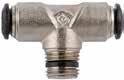
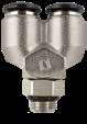
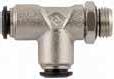
50225N-6-M12x1,56M12x1,5 .295(7,5).827(21).866(22).433(11).63(16).492(12,5)
50100N-6-1/861/8 .295(7,5).827(21).689(17,5).433(11).492(12,5) 50100N-6-1/461/4 .433(11).827(21).846(21,5).433(11).492(12,5)
50100N-8-1/4
.433(11).886(22,5).846(21,5).512(13).551(14)
50100N-10-1/4101/4 .433(11)1.043(26,5).965(24,5).63(16).669(17)
50100N-10-3/8103/8 .453(11,5)1.043(26,5).945(24).63(16).669(17)
50100N-12-1/4121/4 .433(11)1.201(30,5)1.201(28).748(19).846(21,5)
50100N-12-3/8123/8 .453(11,5)1.201(30,5)1.201(28).748(19).846(21,5)
4.9 50 N Serie s 50225N SWIVEL RUN TEE 50326N Y-CONNECTOR MALE ADAPTOR (PARALLEL) 50100N FIXED ELBOW 50200N FIXED BRANCH TEE Part No. TubeA BL1L2CH1CH2D 50225N-3-M53M5 .138(3,5).650(16,5).669(17).354(9).315(8).394(10) 50225N-4-M5 5/32 (4) M5 .138(3,5).669(17).709(18).354(9).315(8).394(10)
5/32 (4) 1/8 .217(5,5).669(17).728(18,5).354(9).512(13).394(10)
5/32 (4) 1/4 .276(7).669(17).787(20).354(9).63(16).394(10)
50225N-4-1/8
50225N-4-1/4
50225N-5-M55M5 .138(3,5).787(20).807(20,5).433(11).433(11).492(12,5)
50225N-8-1/8 5/16 (8) 1/8 .217(5,5).886(22,5).886(22,5).512(13).512(13).571(14,5) 50225N-8-1/4 5/16 (8) 1/4 .276(7).886(22,5).906(23).512(13).63(16).571(14,5) 50225N-8-3/8 5/16 (8) 3/8 .315(8).886(22,5).984(25).512(13).787(20).571(14,5) 50225N-8-1/2 5/16 (8) 1/2 .374(9,5).886(22,5)1.043(26,5).512(13).984(25).571(14,5) 50225N-10-1/4101/4 .276(7)1.043(26,5)1.063(27).551(14).63(16).689(17,5) 50225N-10-3/8103/8
BSPP D A B L2 L1 L1 CH1 CH2 Part No. TubeA BCCH1CH2D
5/32
1/8
50326N-6-1/861/8 .217(5,5)1.456(37).511(13).511(13).492(12,5) 50326N-6-1/461/4 .275(7)1.516(38,5).629(16).511(13).492(12,5) 50326N-8-1/8 5/16 (8) 1/8 .217(5,5)1.594(40,5).511(13).590(15).551(14) 50326N-8-1/4 5/16 (8) 1/4 .275(7)1.614(41).629(16).590(15).551(14) 50326N-8-3/8 5/16 (8) 3/8 .314(8)1.693(43).787(20).590(15).551(14) BSPP A B L C CH2 CH1 D Part No. TubeA BL1L2CHD 50100N-4-M5 5/32 (4) M5 .197(5).669(17).591(15).354(9).394(10) 50100N-4-1/8 5/32 (4) 1/8 .295(7,5).669(17).61(15,5).354(9).394(10) 50100N-5-M55M5 .197(5).787(20).669(17).433(11).492(12,5) 50100N-5-1/851/8 .295(7,5).787(20).689(17,5).433(11).492(12,5)
50326N-4-1/8
(4)
.217(5,5)1.280(32,5).511(13).433(11).394(10)
50100N-8-1/8 5/16 (8) 1/8
.295(7,5).886(22,5).748(19).512(13).551(14)
5/16 (8) 1/4
BSPT CH L1 L 2 B A D Part No. TubeA BL1L2CHD 50200N-4-M5 5/32 (4) M5 .197(5)1.339(34).591(15).354(9).394(10) 50200N-4-1/8 5/32 (4) 1/8 .295(7,5)1.339(34).61(15,5).354(9).394(10) 50200N-5-1/851/8 .295(7,5)1.575(40).689(17,5).433(11).492(12,5)
50200N-8-1/8 5/16 (8) 1/8 .295(7,5)1.772(45).748(19).512(13).551(14) 50200N-8-1/4 5/16 (8) 1/4 .433(11)1.772(45).846(21,5).512(13).551(14)
.453(11,5)2.087(53).945(24).63(16).669(17)
BSPT CH L1 D A B L2 Page 55
50200N-6-1/861/8 .295(7,5)1.654(42).689(17,5).433(11).492(12,5)
50200N-10-1/4101/4 .433(11)2.087(53).965(24,5).630(16).669(17) 50200N-10-3/8103/8
50200N-12-1/4121/4 .433(11)2.402(61)1.102(28).748(19).846(21,5) 50200N-12-3/8123/8 .453(11,5)2.402(61)1.102(28).748(19).846(21,5)
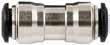
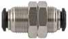
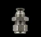
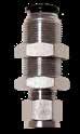

4.10 50 N Serie s 50040N UNION 50050N BULKHEAD UNION 50055N FEMALE BULKHEAD CONNECTOR 50465N BULKHEAD CONNECTOR 50130N UNION ELBOW Part No. TubeTube LB 50040N-33 1.024(26).335(8,5) 50040N-4 5/32 (4) 1.200(30,5).413(10,5) 50040N-55 1.299(33).453(11,5) 50040N-6-46 5/32 (4) 1.259(32).492(12,5) 50040N-66 1.338(34).492(12,5) 50040N-8-6 5/16 (8) 6 1.377(35).571(14,5) 50040N-8 5/16 (8) 1.417(36).571(14,5) 50040N-10-810 5/16 (8) 1.594(40,5).689(17,5) 50040N-1010 1.653(42).689(17,5) 50040N-12-101210 1.791(45,5).807(20,5) 50040N-1212 1.850(47).807(20,5) 50040N-1414 1.929(49).846(21,5) B L Part No. TubeM LCHAmax 50050N-33M10x1 1.024(26).551(14).197(5) 50050N-4 5/32 (4) M12x1 1.240(31,5).669(17).275(7) 50050N-55M14x1 1.299(33).669(17).275(7) 50050N-66M14x1 1.377(35).669(17).374(9,5) 50050N-8-6 5/16 (8)-6 M16x1 1.456(37).748(19).413(10,5) 50050N-8 5/16 (8) M16x1 1.456(37).748(19).413(10,5) 50050N-10-610-6M20x1 1.693(43).944(24).453(11,5) 50050N-10-8 10-5/16 (8) M20x1 1.693(43).944(24).492(12,5) 50050N-1010M20x1 1.692(42).944(24).492(12,5) 50050N-1212M22x1 1.889(48)1.023(26).649(16,5) 50050N-1414M23x1 1.929(49)1.063(26).649(16,5) L A max CH M Part No. TubeA BMSmaxCH1CH2CDL 50055N-4-1/8 5/32 (4) 1/8 .334(8,5)M12X1.275(7).591(15).669(17).394(10).748(19)1.141(29) 50055N-6-1/861/8 .334(8,5)M14X1.315(8).630(16).669(17).394(10).826(21)1.221(31) 50055N-6-1/461/4 .433(11)M14X1.315(8).630(16).669(17).472(12).826(21)1.300(33) 50055N-8-1/8 5/16 (8) 1/8 .334(8,5)M16X1.315(8).709(18).748(19).394(10).866(22)1.260(32) 50055N-8-1/4 5/16 (8) 1/4 .433(11)M16X1.315(8).709(18).748(19).472(12).866(22)1.339(34) 50055N-10-3/8103/8 .472(12)M20X1.374(9.5).945(24).945(24).551(14)1.003(25.5)1.556(38,5) 50055N-12-3/8123/8 .472(12)M22X1.413(10,5).945(24)1.024(26).591(15)1.083(27.5)1.673(42.5) 50055N-12-1/2121/2 .591(15)M22X1.413(10,5).945(24)1.024(26).669(17)1.083(27.5)1.752(44.5) M CH2 L D S max C CH1 A B Part No. Tube LDCH1CH2CH3 50465N-66 1.949(49.5).492(12.5).511(13).669(17).669(17) 50465N-8 5/16 (8) 2.047(52).551(14).551(14).748(19).748(19) 50465N-1010 2.282(59).669(17).748(19).945(24).945(24) L ØD CH3 CH1 CH2 Part No. Tube LCHD 50130N-33 .669(17).354(9).394(10) 50130N-4 5/32 (4) .669(17).354(9).394(10) 50130N-55 .787(20).433(11).492(12,5) 50130N-66 .826(21).433(11).492(12,5) 50130N-8 5/16 (8) .885(22,5).511(13).571(14,5) 50130N-1010 1.043(26,5).629(16).689(17,5) 50130N-1212 1.200(30,5).748(19).846(21,5) 50130N-1414 1.279(32,5).748(19).846(21,5) CH L L D Page 56
Part No. TubeA BLCHD
50500N-5-M55M5 .492(12,5).787(20)-.492(12,5)
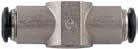

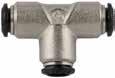
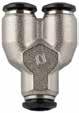
50500N-5-M65M6 .492(12,5).787(20)-.492(12,5)
50500N-5-1/851/8 .591(15).846(21,5).551(14).492(12,5)
50500N-5-1/451/4 .669(17).965(24,5).709(18).492(12,5)
50500N-6-M56M5 .492(12,5).807(20,5)-.492(12,5)
50500N-6-M66M6 .492(12,5).807(20,5)-.492(12,5)
50500N-6-1/861/8
4.11 50 N Serie s 50310N UNION Y 50230N UNION TEE 50500N SINGLE BANJO BODY 50510N DOUBLE BANJO BODY Part No. Tube ALCHD 50310N-33 .394(10)1.142(29).433(11).394(10) 50310N-4 5/32 (4) .433(11)1.259(32).433(11).394(10) 50310N-55 .531(13.5)1.377(35).511(13).492(12,5) 50310N-66 .531(13.5)1.437(36,5).511(13).492(12,5) 50310N-8 5/16 (8) .610(15.5)1.614(41).590(15).551(14) 50310N-1010 .728(18.5)1.889(48).708(18).669(17) D2 D1 A D2 D L CH Part No. Tube L1L2CHD 50230N-33 1.338(34).669(17).354(9).394(10) 50230N-4 5/32 (4) 1.338(34).669(17).354(9).394(10) 50230N-55 1.574(40).787(20).433(11).492(12,5) 50230N-66 1.653(42).826(21).433(11).492(12,5) 50230N-8 5/16 (8) 1.771(45).885(22,5).511(13).551(14) 50230N-1010 2.086(53)1.043(26,5).629(16).669(17) 50230N-1212 2.401(61)1.200(30,5).748(19).847(21,5) 50230N-1414 2.578(65,5)1.279(32,5).748(19).847(21,5) L1 D D L2 CH
50500N-3-M53M5 .492(12,5).748(19)-.394(10) 50500N-3-M63M6 .492(12,5).748(19)-.394(10) 50500N-4-M5 5/32 (4) M5 .492(12,5).748(19)-.394(10) 50500N-4-M6 5/32 (4) M6
5/32 (4) 1/8 .591(15).827(21).551(14).394(10)
.492(12,5).748(19)-.394(10) 50500N-4-1/8
50500N-8-1/8 5/16 (8) 1/8 .591(15).945(24).551(14).551(14) 50500N-8-1/4 5/16 (8) 1/4 .669(17)1.024(26).709(18).551(14) 50500N-8-3/8 5/16 (8) 3/8 .787(20)1.102(28).827(21).551(14) 50500N-10-1/4101/4 .669(17)1.142(29).709(18).669(17) 50500N-10-3/8103/8 .787(20)1.201(30,5).827(21).669(17) 50500N-12-3/8123/8 .787(20)1.280(32,5).827(21).846(21,5) 50500N-12-1/2121/2 .945(24)1.378(35).984(25).846(21,5) 50500N-14-1/2141/2 .945(24)1.398(35,5).984(25).846(21,5) ForBANJOSTEMassembliessee10.7/10.8/10.9 A B D L CH Part No. TubeA BLCHD 50510N-4-M5 5/32 (4) M5 .492(12,5)1.496(38)-.394(10) 50510N-4-M6 5/32 (4) M6 .492(12,5)1.496(38)-.394(10) 50510N-4-1/8 5/32 (4) 1/8 .591(15)1.654(42).551(14).394(10) 50510N-5-1/851/8 .591(15)1.693(43).551(14).492(12,5) 50510N-5-1/451/4 .669(17)1.929(49).709(18).492(12,5) 50510N-6-1/861/8 .591(15)1.732(44).551(14).492(12,5) 50510N-6-1/461/4 .669(17)1.969(50).709(18).492(12,5) 50510N-8-1/8 5/16 (8) 1/8 .591(15)1.890(48).551(14).551(14) 50510N-8-1/4 5/16 (8) 1/4 .669(17)2.047(52).709(18).551(14) ForBANJOSTEMassembliessee10.7/10.8/10.9 A B D L CH Page 57
.591(15).866(22).551(14).492(12,5) 50500N-6-1/461/4 .669(17).984(25).709(18).492(12,5)
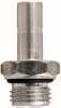
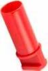
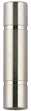
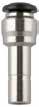
4.12 50 N Serie s 50600 STANDPIPE 50610 POLYAMIDE PLUG 50625 DOUBLE JOINT 50700N TUBE REDUCER Part No. DA BLL1CH 50600-4-M5 5/32 (4) M5 .157(4).945(24).591(15).315(8) 50600-4-1/8 5/32 (4) 1/8 .236(6)1.043(26,5).591(15).512(13) 50600-5-M55M5 .157(4)1.024(26).669(17).315(8) 50600-5-1/851/8 .236(6)1.122(28,5).669(17).512(13) 50600-5-1/451/4 .315(8)1.220(31).669(17).630(16) 50600-6-M56M5 .157(4)1.024(26).669(17).315(8) 50600-6-1/861/8 .236(6)1.122(28,5).669(17).512(13) 50600-6-1/461/4 .315(8)1.220(31).669(17).630(16) 50600-8-1/8 5/16 (8) 1/8 .236(6)1.161(29,5).709(18).512(13) 50600-8-1/4 5/16 (8) 1/4 .315(8)1.260(32).709(18).630(16) 50600-8-3/8 5/16 (8) 3/8 .354(9)1.319(33,5).709(18).787(20) 50600-10-1/8101/8 .236(6)1.319(33,5).866(22).512(13) 50600-10-1/4101/4 .315(8)1.417(36).866(22).630(16) 50600-10-3/8103/8 .354(9)1.476(37,5).866(22).787(20) 50600-12-1/4121/4 .315(8)1.516(38,5).965(24,5).630(16) 50600-12-3/8123/8 .354(9)1.575(40).965(24,5).787(20) 50600-14-1/2141/2 .394(10)1.732(44)1.043(26,5).945(24) BSPP D A B CH L1 L Part No. 0D1 GLL1 50610-3 3 .197(5)1.201(30,5).709(18) 50610-4 5/32 (4) .236(6)1.162(29,5).611(15,5) 50610-5 5 .276(7)1.319(33,5).709(18) 50610-6 6 .315(8)1.260(32).611(15,5) 50610-8 5/16 (8) .394(10)1.398(35,5).768(19.5) 50610-10 10 .472(12)1.575(40).768(19.5) 50610-12 12 .551(14)1.634(41.5).787(20) 50610-14 14 .630(16)1.654(42).768(19.5) Ø D1 L G L1 Part No. Tube L 50625-4 5/32 (4) 1.220(31) 50625-5 5 1.299(33) 50625-6 6 1.339(34) 50625-8 5/16 (8) 1.417(36) 50625-10 10 1.772(45) 50625-12 12 1.969(50) L Part No. A B LD 50700N-4-3 5/32 (4) 3 1.181(30).335(8,5) 50700N-5-4 5 5/32 (4) 1.260(32).453(11,5) 50700N-6-4 6 5/32 (4) 1.181(30).413(10,5) 50700N-6-5 6 5 1.358(34,5).453(11,5) 50700N-8-4 5/16 (8) 5/32 (4) 1.280(32,5).413(10,5) 50700N-8-6 5/16 (8) 6 1.358(34,5).492(12,5) 50700N-10-4 10 5/32 (4) 1.240(31,5).413(10,5) 50700N-10-6 10 6 1.476(37,5).492(12,5) 50700N-10-8 10 5/16 (8) 1.516(38,5).571(14,5) 50700N-12-8 12 5/16 (8) 1.555(39,5).571(14,5) 50700N-12-1012 10 1.693(43).689(17,5) B A L Page 58
Part No. Tube DH1H2
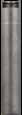
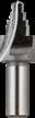
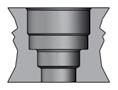

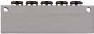
55800N-33 .264(6,7).354(9).197(5)
55800N-4 5/32 (4) .343(8,7).410(10,4).221(5,6)
55800N-55 .384(9,75).465(11,8).248(6,3)
55800N-66 .423(10,75).488(12,4).272(6,9)
55800N-8 5/16 (8) .500(12,7).488(12,4).272(6,9)
55800N-1010 .618(15,7).618(15,7).335(8,5)
55800N-1212 .721(18,3).701(17,8).374(9,5)
Seatsdimensionspush-fitcartridges.
Tube D1D2D3D4H1H2H3R
1/8 (3) .134(3,4).238(6,05).252(6,4).274(6,96).146(3,7).240(6,1).339(8,6).020(0,5)
5/32 (4) .165(4,2).293(7,45).331(8,4).354(9).148(3,76).256(6,5).374(9,5).020(0,5)
1/5 (5) .205(5,2).329(8,36).370(9,4).400(10,16).175(4,45).311(7,9).413(10,5).020(0,5)
1/4 (6) .244(6,2).368(9,35).411(10,44).447(11,35).197(5).335(8,5).453(11,5).020(0,5)
5/16 (8) .323(8,2).449(11,4).488(12,4).508(12,9).205(5,2).335(8,5).492(12,5).030(0,76) 3/8 (10) .402(10,2).571(14,5).606(15,4).630(16).264(6,7).413(10,5).591(15).030(0,76)
4.13 50 N Serie s
5 WAY ALUMINUM MANIFOLD 55800N PUSH-FIT CARTRIDGES SEAT 55801 TOOL FOR PUSH-FIT CARTRIDGES SEAT 55802
TOOL FOR PUSH-FIT CARTRIDGES Part No. TubeA HFSCDLL1L2 50900N-4-1/8 5/32 (4) 1/8 2.224(66).197(5).177(4,5).591(15).984(25)2.953(75).472(12).531(13,5) 50900N-6-1/861/8 3.150(80).197(5).177(4,5).591(15).984(25)3.543(90).571(14,5).630(16) 50900N-6-1/461/4 3.150(80).197(5).177(4,5).787(20)1.181(30)3.543(90).571(14,5).630(16) 50900N-8-1/4 5/16 (8) 1/4 3.543(90).197(5).177(4,5).787(20)1.181(30)3.937(100).630(16).709(18) L L2 L2 L1 L1 L1 A C L H S F
50900N
ASSEMBLING
H1 H2 D
1/2 (12) .480(12,2).669(17).709(18).748(19).295(7,5).476(12,1).669(17).039(1)
D4 ± 70° R. .0019 D3 + .0019 0 D2 + .0039 0 .0039 0 .0078 0 D1 + .0039 0 H1 ± .0019 H2 + H1 + Part No. Tube øBody 55801-33 .394(10) 55801-4 4 (5/32) .394(10) 55801-6 6 (1/4) .472(12) 55801-8 8 (5/16) .472(12) 55801-10 10 (3/8) .630(16) 55801-12 12 (1/2) .630(16) Part No. Tube 55802-3 3 55802-4 4 (5/32) 55802-6 6 (1/4) 55802-8 8 (5/16) 55802-10 10 (3/8) 55802-12 12 (1/2) Page 59
PUSH-FIT CARTRIDGES ASSEMBLING INSTRUCTIONS ART. 55800N 1 2
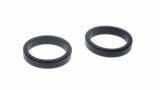
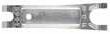
50980
SECURITY CLIPS
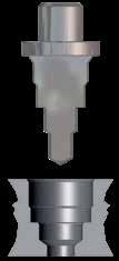
50991
TOOL FOR DISASSEMBLING
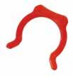
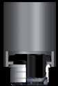
50006
THREAD
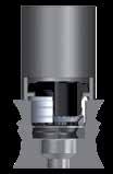
PACKING FOR THE SWIFTFIT TAPER THREADS
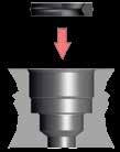
4.14 50 N Serie s
Make the seat for the cartridge utilizing the suitable tool Art. 55801.
Insert the lip seal inside of the seat.
3 4
Insert the cartridge into the assembling tool Art. 55802.
Press the cartridge inside of the seat until it will be reached the abutment surface with the assembling tool.
Part No. Tube 50980-53 5/32 (4) 50980-5 3/16 (5) 50980-04 1/4 (6) 50980-05 5/16 (8) 50980-06 3/8 (10) 50980-08 1/2 (12) 50980-14 (14) Part No. 50991 468 1012 Part No. Thread 50006-02 1/8 50006-04 1/4 50006-06 3/8 50006-08 1/2 Page 60
FITTING KITS
4.15 50 N Serie s
FITTING KIT - 4MM TUBE 50861N-6 FITTING KIT - 6MM TUBE 50861N-8 FITTING KIT - 8MM TUBE Part No. Description Qty 50000N-4-1/8 Straight4mmTubex1/8Male5 50000N-4-1/4 Straight4mmTubex1/4Male5 50110N-4-1/8 SwivelElbow4mmTubex1/8Male5 50110N-4-1/4 SwivelElbow4mmTubex1/4Male5 50210N-4-1/8 BranchTee4mmTubex1/8Male5 50210N-4-1/4 BranchTee4mmTubex1/4Male5 50222N-4-1/8 RunTee4mmTubex1/8Male5 50222N-4-1/4 RunTee4mmTubex1/4Male5 50040N-4 Union4mmTube5 50050N-4 BulkheadUnion4mmTube5 50130N-4 UnionElbow4mmTube5 50230N-4 UnionTee4mmTube5 Part No. Description Qty 50000N-6-1/8 Straight6mmTubex1/8Male5 50000N-6-1/4 Straight6mmTubex1/4Male5 50110N-6-1/8 SwivelElbow6mmTubex1/8Male5 50110N-6-1/4 SwivelElbow6mmTubex1/4Male5 50210N-6-1/8 BranchTee6mmTubex1/8Male5 50210N-6-1/4 BranchTee6mmTubex1/4Male5 50222N-6-1/8 RunTee6mmTubex1/8Male5 50222N-6-1/4 RunTee6mmTubex1/4Male5 50040N-6 Union6mmTube5 50050N-6 BulkheadUnion6mmTube5 50130N-6 UnionElbow6mmTube5 50230N-6 UnionTee6mmTube5 Part No. Description Qty 50000N-8-1/8 Straight8mmTubex1/8Male5 50000N-8-1/4 Straight8mmTubex1/4Male5 50000N-8-3/8 Straight8mmTubex3/8Male5 50110N-8-1/8 SwivelElbow8mmTubex1/8Male5 50110N-8-1/4 SwivelElbow8mmTubex1/4Male5 50110N-8-3/8 SwivelElbow8mmTubex3/8Male5 50210N-8-1/8 BranchTee8mmTubex1/8Male5 50210N-8-1/4 BranchTee8mmTubex1/4Male5 50040N-8 Union8mmTube5 50050N-8 BulkheadUnion8mmTube5 50130N-8 UnionElbow8mmTube5 50230N-8 UnionTee8mmTube5 Page 61
50861N-4
4.16 50 N Serie s
KIT
12MM TUBE Part No. Description Qty 50000N-10-1/4 Straight10mmTubex1/4Male3 50000N-10-3/8 Straight10mmTubex3/8Male3 50110N-10-1/4 SwivelElbow10mmTubex1/4Male3 50110N-10-3/8 SwivelElbow10mmTubex3/8Male3 50210N-10-1/4 BranchTee10mmTubex1/4Male3 50210N-10-3/8 BranchTee10mmTubex3/8Male3 50222N-10-1/4 RunTee10mmTubex1/4Male3 50222N-10-3/8 RunTee10mmTubex3/8Male3 50040N-10 Union10mmTube3 50050N-10 BulkheadUnion10mmTube3 50130N-10 UnionElbow10mmTube3 50230N-10 UnionTee10mmTube3 Part No. Description Qty 50000N-12-3/8 Straight12mmTubex3/8Male3 50000N-12-1/2 Straight12mmTubex1/2Male3 50110N-12-3/8 SwivelElbow12mmTubex3/8Male3 50110N-12-1/2 SwivelElbow12mmTubex1/2Male3 50210N-12-3/8 BranchTee12mmTubex3/8Male3 50210N-12-1/2 BranchTee12mmTubex1/2Male3 50222N-12-3/8 RunTee12mmTubex3/8Male3 50222N-12-1/2 RunTee12mmTubex1/2Male3 50040N-12 Union12mmTube3 50050N-12 BulkheadUnion12mmTube3 50130N-12 UnionElbow12mmTube3 50230N-12 UnionTee12mmTube3 Page 62
50861N-10 FITTING KIT - 10MM TUBE 50861N-12 FITTING
-
85 Series
For STRAIGHT FITTINGS see 87-88 series


Aignep reserves the right to vary models and dimensions without notice
85110 Pg.5.5 85240 Pg.5.9 85222 Pg.5.6 50980 Pg.5.12 85170 Pg.5.5 85310 Pg.5.9 85320 Pg.5.6 85210 Pg.5.5 85330 Pg.5.9 85040 Pg.5.7 85222 Pg.5.6 85350 Pg.5.9 85130 Pg.5.7 85320 Pg.5.6 85500 Pg.5.10 85140 Pg.5.8 85340 Pg.5.7 85510 Pg.5.10 85150 Pg.5.8 85110 Pg.5.5 85705 Pg.5.11 85180 Pg.5.8 85360 Pg.5.7 85700 Pg.5.11 85160 Pg.5.8 85210 Pg.5.5 88610B Pg.5.11 85230 Pg.5.8 87000 Pg.3.5 87010 Pg.3.5 88007 Pg.3.7 55625 Pg.5.12 85520 Pg.5.10 85620 Pg.5.10 Page 63
NYLON PUSH-TO-CONNECT FITTINGS FOR INCH TUBE
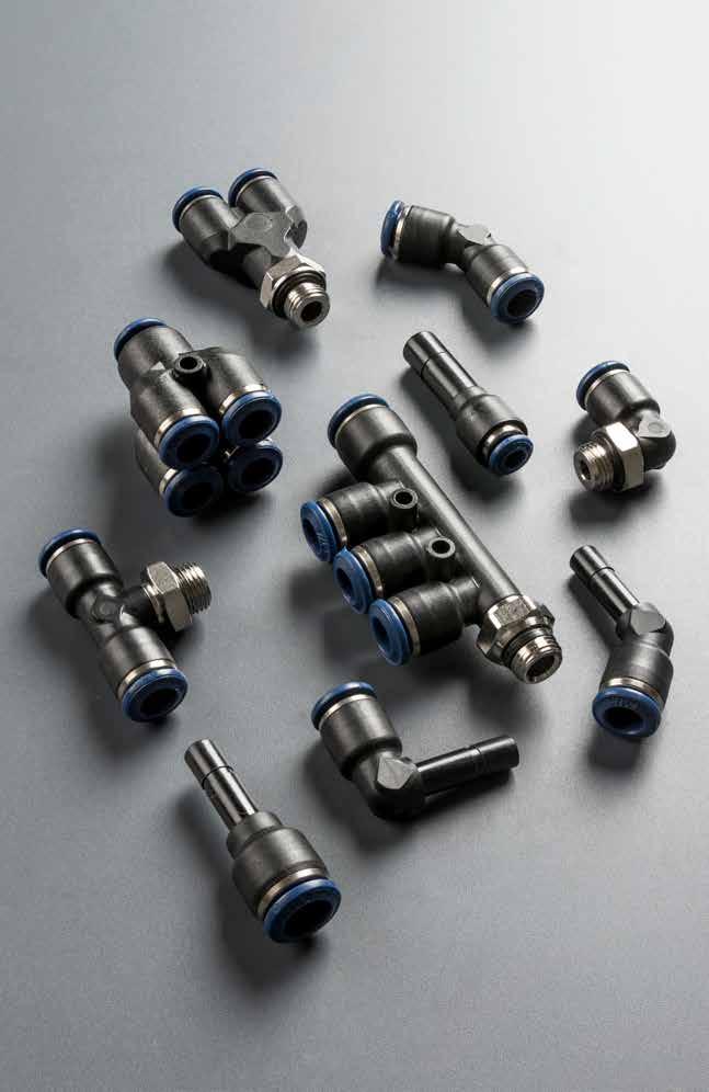
85
85000 Page 64
Series
Reference Standard
TECHNICAL CHARACTERISTICS
Bar
Pressure Rating
Vacuum ~ 290 PSI
-0.99 bar ~ 20 bar
-0.099 MPa ~ 2.0 MPa
Media
Compressed air
• Vacuum
• Water
Applications
• Pneumatic Automation
• Automotive
• Textile, Packaging
• Compressed Air Circuit Vacuum
Advantages
1 The 303 Stainless Steel gripper ensures a tight clamp for tubes of any material without damaging the tube’s surface. The secure connection between the tube and the fitting will hold up to severe conditions such as impact and vibrations.
2 The shape of the safety ring and the molded seal perfectly seal off the tube, creating a vacuum.
3 Series with several types of threads: SWIFTFIT
4 All straight fittings can be tightened with an Allen wrench because of our internal hex design. This enables the end user to tighten the fitting in spaces too small for an openend wrench.
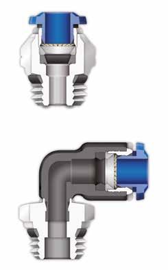
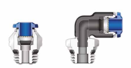
Component Parts and Materials
1 Composite Release Collet
2 Nylon Body
3 NBR Thread Seal
4 Nickel Plated Brass Sleeve
5 303 Stainless Steel Gripper
6 Technopolymer Safety Ring
7 NBR Molded Seal
8 Nickel Plated Thread Brass Body
9 NBR Seal
Tubing Compatibility
Nylon 6 - 11 -12
Polyethylene
Polyurethane (“98 Shore A for best result)
PTFE FEP
5.3 8 5 Serie s 1907/2006 2011/65/CE ISO 14743:2004 SILICON FREE PED 2014/68/UE
UNF
NBR -4º F ~ 176º F -20º C ~ 80º C Temperatures Rating 1 2 3 4 5 6 7 8 9 8 1 3 4 2 Page 65
THREADS & ADVANTAGES
The SWIFTFIT Universal Thread has been designed to offer the following advantages to the end users:
• Reduced overall length
• Smaller hex dimensions compared to parallel threads
• Fits with various parallel and tapered threads
All SWIFTFIT fittings have been equipped with threads and an NBR thread seal that will universally connect to all thread types.
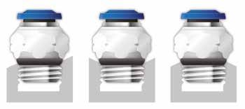
Our SWIFTFIT universal fittings also work on non-flat surfaces without compromising an air-tight seal.
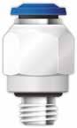
UNF Threads
The UNF Thread has been designed to offer the following advantages to the end users:
• Standard USA design
• Designed for use in UNF connections with an integrated NBR o-ring that provides a perfect seal
5.4 8 5 Serie s
Torque Specifications Recommended Torque Thread Size Min. Max. 1/8 5 Nm 7 Nm 1/4 5 Nm 7 Nm 3/8 5 Nm 7 Nm 1/2 5 Nm 7 Nm Torque Specifications Recommended Torque Thread Size Min. Breaking Torque 10/32 0.8 Nm 3.2 Nm NPT NPTF Tapered ISO 228 BSP PF Parallell ISO 7 BSPT PT Tapered ISO 7 BSPP Parallell
Inclined
Page 66
One fitting... Endless possibilities
Concave Convex
85110
SWIVEL ELBOW
* For part numbers with 10-32 threads
85170
45° SWIVEL ELBOW
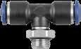
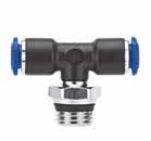
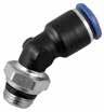

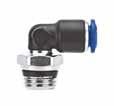
85210
SWIVEL BRANCH TEE
.275(7)1.200(30.5).905(23).629(16).629(16).787(20) 85110-08-061/23/8 .295(7.5)1.200(30.5).905(23).629(16).669(17).787(20) 85110-08-081/21/2 .354(9)1.200(30.5)1.003(25.5).629(16).826(21).787(20)
Part No. TubeA BL1L2CH1CH2D
.216(5,5)1.200(30,5).728(18,5).275(7).511(13).393(10)
.275(7)1.200(30,5).787(20).275(7).590(15).393(10)
.275(7)1.594(40,5).846(21,5).354(9).590(15).492(12,5)
.216(5,5)1.732(44).826(21).394(10).511(13).551(14)
.275(7)1.732(44).885(22,5).394(10).590(15).551(14)
.295(7,5)1.732(44).905(23).394(10).669(17).551(14)
* For part numbers with 10-32 threads
.354(9)2.086(53)1.023(26).551(13).826(21).669(17)
.275(7)2.362(60)1.062(27).629(16).629(16).787(20)
.295(7,5)2.362(60)1.062(27).629(16).669(17).787(20)
5.5 8 5 Serie s
Part No. TubeA BL1L2CH1CH2D 85110-02-021/81/8 .216(5.5).610(15).649(15.5).275(7).511(13).393(10) 85110-02-041/81/4 .275(7).610(15).708(18).275(7).591(15).393(10) *85110-53-32 5/32 (4) 10/32 .157(4).649(16.5).567(14.5).275(7).354(9).393(10) 85110-53-02 5/32 (4) 1/8 .216(5.5).649(16.5).649(15.5).275(7).511(13).393(10) 85110-53-04 5/32 (4) 1/4 .275(7).649(16.5).708(18).275(7).591(15).393(10) *85110-04-321/410/32 .157(4).807(20.5).610(15.5).354(9).354(9).492(12.5) 85110-04-021/41/8 .216(5.5).807(20.5).688(17.5).354(9).511(13).492(12.5) 85110-04-041/41/4 .275(7).807(20.5).748(19).354(9).591(15).492(12.5) 85110-04-061/43/8 .295(7.5).807(20.5).787(20).354(9).669(17).492(12.5) 85110-04-081/41/2 .354(9).807(20.5).866(22).354(9).826(21).492(12.5) 85110-05-02 5/16 (8) 1/8 .216(5.5).866(22).728(18.5).394(10).511(13).551(14) 85110-05-04 5/16 (8) 1/4 .275(7).866(22).787(20).394(10).591(15).551(14) 85110-05-06 5/16 (8) 3/8 .295(7.5).866(22).807(20.5).394(10).669(17).551(14) 85110-05-08 5/16 (8) 1/2 .354(9).866(22).905(23).394(10).826(21).551(14) 85110-06-043/81/4 .275(7)1.043(26.5).866(22).551(13).629(16).669(17) 85110-06-063/83/8
85110-06-083/81/2
85110-08-041/21/4
CH1 CH2 L1 A B D L2 UNF CH2 CH1 A L2 B L1 D Part No. TubeA BL1L2CH1CH2D 85170-53-02 5/32 (4) 1/8 .217(5,5).492(12,5).650(16,5).276(7).512(13).394(10) 85170-04-021/41/8 .217(5,5).807(20,5).689(17,5).354(9).512(13).472(12) 85170-04-041/41/4 .276(7).807(20,5).744(18,9).354(9).591(15).472(12) 85170-05-02 5/16 (8) 1/8 .217(5,5).866(22).728(18,5).394(10).512(13).551(14) 85170-05-04 5/16 (8) 1/4 .276(7).866(22).787(20).394(10).591(15).551(14) 85170-05-06 5/16 (8) 3/8 .295(7,5).866(22).807(20,5).394(10).669(17).551(14) 85170-06-043/81/4 .276(7)1043(26,5).858(21,8).512(13).630(16).669(17) 85170-06-063/83/8 .295(7,5)1043(26,5).858(21,8).512(13).669(17).669(17)
85170-08-061/23/8
85170-08-081/21/2
D L2 L1 A B CH1 CH2
.295(7.5)1.043(26.5).866(22).551(13).669(17).669(17)
.354(9)1.043(26.5).964(24.5).551(13).826(21).669(17)
85170-06-083/81/2 .354(9)1043(26,5).964(24,5).512(13).827(21).669(17) 85170-08-041/21/4 .276(7)1.181(30).909(23,1).630(16).630(16).787(20)
.295(7,5)1.181(30).909(23,1).630(16).669(17).787(20)
.354(9)1.181(30)1.003(25,5).630(16).827(21).787(20)
85210-02-021/81/8
85210-02-041/81/4
*85210-53-32 5/32 (4) 10/32 .157(4)1.200(30,5).629(16).275(7).354(9).393(10) 85210-53-02 5/32 (4) 1/8 .216(5,5)1.299(33).728(18,5).275(7).511(13).393(10) 85210-53-04 5/32 (4) 1/4 .275(7)1.299(33).787(20).275(7).590(15).393(10) *85210-04-321/410/32
85210-04-021/41/8
85210-04-041/41/4
85210-05-02 5/16 (8) 1/8
85210-05-04 5/16 (8) 1/4
85210-05-06 5/16 (8) 3/8
85210-06-043/81/4
85210-06-063/83/8
85210-06-083/81/2
85210-08-061/23/8
CH2 CH1 B A L2 L1 D UNF CH1 CH2 B A L2 D L1 Page 67
.157(4)1.594(40,5).610(15,5).354(9).354(9).492(12,5)
.216(5,5)1.594(40,5).787(20).354(9).511(13).492(12,5)
.275(7)2.086(53)1.023(26).551(13).629(16).669(17)
.295(7,5)2.086(53)1.023(26).551(13).669(17).669(17)
85210-08-041/21/4
85210-08-081/21/2 .354(9)2.362(60)1.161(29.5).629(16).826(21).787(20)
85222
SWIVEL RUN TEE
* For part numbers with 10-32 threads
85320
UNION Y
* For part numbers with 10-32 threads
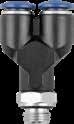
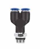
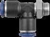
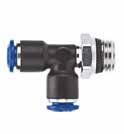
5.6 8 5 Serie s
Part No. TubeA BL1L2CH1CH2D 85222-02-021/81/8 .216(5,5).610(15).708(18).275(7).511(13).393(10) 85222-02-041/81/4 .275(7).610(15).767(19,5).275(7).590(15).393(10) *85222-53-32 5/32 (4) 10/32 .157(4).649(16,5).629(16).275(7).354(9).393(10) 85222-53-02 5/32 (4) 1/8 .216(5,5).649(16,5).708(18).275(7).511(13).393(10) 85222-53-04 5/32 (4) 1/4 .275(7).649(16,5).767(19,5).275(7).590(15).393(10) *85222-04-321/410/32 .157(4).807(20,5).570(14,5).354(9).354(9).492(12,5) 85222-04-021/41/8 .216(5,5).807(20,5).688(17,5).354(9).511(13).492(12,5) 85222-04-041/41/4 .275(7).807(20,5).748(19).354(9).590(15).492(12,5) 85222-05-02 5/16 (8) 1/8 .216(5,5).866(22).748(19).394(10).511(13).551(14) 85222-05-04 5/16 (8) 1/4 .275(7).866(22).807(20,5).394(10).590(15).551(14) 85222-05-06 5/16 (8) 3/8 .295(7,5).866(22).826(21).394(10).669(17).551(14) 85222-06-043/81/4 .275(7)1.043(26,5).866(22).551(13).629(16).669(17) 85222-06-063/83/8 .295(7,5)1.043(26,5).866(22).551(13).669(17).669(17) 85222-06-083/81/2 .354(9)1.043(26,5).964(24,5).551(13).826(21).669(17) 85222-08-041/21/4 .275(7)1.200(30,5).905(23).629(16).629(16).787(20) 85222-08-061/23/8 .295(7,5)1.200(30,5).905(23).629(16).669(17).787(20) 85222-08-081/21/2 .354(9)1.200(30,5)1.003(25,5).629(16).826(21).787(20) CH1 CH2 A D L1 L1 L2 B UNF CH1 CH2 A D L1 L1 L2 B Part No. TubeA BCLCH1CH2 *85320-53-32 5/32 (4) 10/32 .157(4).433(11)1.437(36,5).393(10).393(10) 85320-53-02 5/32 (4) 1/8 .216(5,5).433(11)1.496(38).393(10).433(11) 85320-53-04 5/32 (4) 1/4 .275(7).433(11)1.594(40,5).393(10).551(14) *85320-04-321/410/32 .157(4).531(13,5)1.633(41,5).472(12).393(10) 85320-04-021/41/8 .216(5,5).511(13)1.692(43).472(12).433(11) 85320-04-041/41/4 .275(7).531(13,5)1.791(45,5).472(12).551(14) 85320-05-02 5/16 (8) 1/8 .216(5,5).610(15,5)1.850(47).551(14).433(11) 85320-05-04 5/16 (8) 1/4 .275(7).610(15,5)1.929(49).551(14).551(14) 85320-05-06 5/16 (8) 3/8 .295(7,5).610(15,5)1.948(49,5).551(14).669(17) 85320-06-043/81/4 .275(7).748(19)2.224(56,5).669(17).551(14) 85320-06-063/83/8 .295(7,5).748(19)2.263(57,5).669(17).669(17) 85320-06-083/81/2 .354(9).748(19)2.362(60).669(17).826(21) 85320-08-061/23/8 .295(7,5).866(22)2.618(66,5).787(20).669(17) 85320-08-081/21/2 .354(9).866(22)2.677(68).787(20).826(21) A C CH1 L B CH2 UNF A C CH1 L B CH2 Page 68
85340
85130 UNION ELBOW
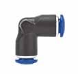
Part No. TubeA BCLHCHF 85340-53-02 5/32 (4) 1/8 .217(5,5).425(10,8)1.555(39,5).846(21,5).433(11).130(3,3)
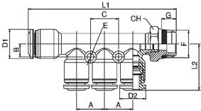
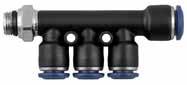
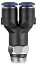
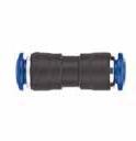
85340-53-04 5/32 (4) 1/4 .276(7).425(10,8)1.654(42).846(21,5).551(14).130(3,3)
85340-04-021/41/8 .217(5,5).531(13,5)1.831(46,5)1.064(27).433(11).130(3,3)
85340-04-041/41/4 .276(7).531(13,5)1.889(48)1.064(27).551(14).130(3,3)
Part No. TubeF ABL1L2CEGHD1D2
85360-04-531/4-5/321/8 .531(13,5).236(6)2.757(70).866(22).531(13,5).551(14).471(12).130(3,3).217(5,5).511(13)
85360-04-531/4-5/321/4 .531(13,5).236(6)2.817(71,5).866(22).531(13,5).551(14).471(12).130(3,3).276(7).591(15)
85360-05-53 5/16-5/32 1/8 .531(13,5).236(6)2.757(70).866(22).531(13,5).551(14).471(12).130(3,3).217(5,5).511(13)
85360-05-53 5/16-5/32 1/4 .531(13,5).236(6)2.817(71,5).866(22).531(13,5).551(14).471(12).130(3,3).276(7).591(15)
85360-05-045/16-1/41/8 .531(13,5).236(6)2.757(70).866(22).531(13,5).551(14).491(12,5).130(3,3).217(5,5).511(13)
85360-05-045/16-1/41/4 .531(13,5).236(6)2.817(71,5).866(22).531(13,5).551(14).491(12,5).130(3,3).276(7).591(15)
85360-04-043/8-1/41/4 .590(15).276(7)3.208(81,5).946(24).590(15).669(17).551(14).130(3,3).276(7).629(16)
85360-04-043/8-1/43/8 .590(15).276(7)3.208(81,5).946(24).590(15).669(17).551(14).130(3,3).296(7,5).669(17)
85360-06-053/8-5/161/4 .590(15).276(7)3.208(81,5).906(23).590(15).669(17).551(14).130(3,3).276(7).629(16)
85360-06-053/8-5/163/8 .590(15).276(7)3.208(81,5).906(23).590(15).669(17).551(14).130(3,3).296(7,5).669(17)
5.7 8 5 Serie s
4
Y
POSITION
UNION B L
85360 REDUCTION MANIFOLD 85040
A L H F C CH B F
Part No. TubeTube BL 85040-02-021/81/8 .394(10)1.102(28) 85040-53-53 5/32 (4)5/32 (4) .394(10)1.220(31) 85040-04-531/4 5/32 (4) .492(12.5)1.358(34.5) 85040-04-041/41/4 .492(12.5)1.377(35) 85040-05-53 5/16 (8)5/32 (4) 1.456(37).551(14) 85040-05-04 5/16 (8) 1/4 .551(14)1.496(38) 85040-05-05 5/16 (8)5/16 (8) .551(14)1.456(37) 85040-06-043/81/4 .669(17)1.751(44.5) 85040-06-053/8 5/16 (8) .669(17)1.751(44.5) 85040-06-063/83/8 .669(17)1.771(45) 85040-08-051/2 5/16 (8) 1.968(50).787(20) 85040-08-061/23/8 .787(20)1.968(50) 85040-08-081/21/2 .787(20)1.929(49) Part No. TubeTube LCHD 85130-02-021/81/8 .610(15.5).354(9).393(10) 85130-53-53 5/32 (4)5/32 (4) .649(16.5).354(9).393(10) 85130-04-041/41/4 .807(20.5).433(11).492(12.5) 85130-05-04 5/16 (8) 1/4 .886(22,5).551(14).511(13) 85130-05-05 5/16 (8)5/16 (8) .866(22).511(13).551(14) 85130-06-043/81/4 1.023(26).669(17).629(16) 85130-04-053/8 5/16 (8) 1.023(26).669(17).629(16) 85130-06-063/83/8 1.043(26.5).629(16).669(17) 85130-04-061/23/8 1.200(30.5).787(20).748(19) 85130-08-081/21/2 1.200(30.5).748(19).787(20) L D D CH L Page 69

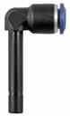
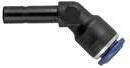
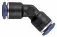
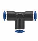
5.8 8 5 Serie s 85140 ELBOW PLUG IN 85150 ELBOW PLUG IN 85160 45° ELBOW PLUG IN 85180 45° UNION 85230 UNION TEE Part No. TubeA BL1L2CH1D 85140-53-53 5/32 (4)5/32 (4) .669(17).650(16,5).819(20,8).276(7).394(10) 85140-53-04 5/32 (4) 1/4 .748(19).650(16,5).913(23).276(7).394(10) 85140-04-531/4 5/32 (4) .669(17).807(20,5).846(21,5).354(9).492(12,5) 85140-04-041/41/4 .748(19).807(20,5).933(23,5).354(9).492(12,5) 85140-04-051/4 5/16 (8) .787(20).886(22,5)1.024(26).394(10).551(14) 85140-05-05 5/16 (8)5/16 (8) .787(20).866(22)1.024(26).394(10).551(14) 85140-05-06 5/16 (8) 3/8 .866(22).866(22)1.083(27,5).394(10).551(14) 85140-06-063/83/8 .886(22,5)1.043(26,5)1.181(30).512(13).669(17) 85140-06-083/81/2 .964(24,5)1.043(26,5)1.260(32).512(13).669(17) 85140-08-081/21/2 1.004(25,5)1.181(30)1.319(33,5).630(16).787(20) L1 A CH1 D B L2 Part No. TubeA BL1L2CH1D 85150-53-53 5/32 (4)5/32 (4) 1.102(28).650(16,5)1.252(31,8).276(7).394(10) 85150-53-04 5/32 (4) 1/4 1.200(30,5).650(16,5)1.359(34,5).276(7).394(10) 85150-04-531/4 5/32 (4) 1.181(30).807(20,5)1.359(34,5).354(9).492(12,5) 85150-04-041/41/4 1.272(32,3).807(20,5)1.457(37).354(9).492(12,5) 85150-05-05 5/16 (8)5/16 (8) 1.417(36).866(22)1.654(42).394(10).551(14) 85150-05-06 5/16 (8) 3/8 1.477(37,5).866(22)1.694(43).394(10).551(14) 85150-06-063/83/8 1.606(40,8)1.043(26,5)1.902(48,3).512(13).669(17) 85150-06-083/81/2 1.692(43)1.043(26,5)1.988(50,5).512(13).669(17) 85150-08-081/21/2 1.850(47)1.220(31)2.165(55).630(16).787(20) L1 A CH1 D B L2 Part No. TubeA BL1L2CHD 85160-53 5/32 (4)5/32 (4) .669(17).492(12,5).827(21).276(7).394(10) 85160-041/41/4 .748(19).807(20,5).925(23,5).354(9).472(12) 85160-05 5/16 (8)5/16 (8) .787(20).866(22).984(25).394(10).551(14) 85160-063/83/8 .886(22,5)1.043(26,5)1.181(30).512(13).669(17) 85160-081/21/2 1.004(25,5)1.181(30)1.319(33,5).630(16).787(20) D L1 L2 B A CH Part No. Tube LCHD 85180-53 5/32 (4) .650(16,5).276(7).394(10) 85180-041/4 .807(20,5).354(9).472(12) 85180-05 5/16 (8) .866(22).394(10).551(14) 85180-063/8 1.043(26,5).512(13).669(17) 85180-081/2 1.181(30).630(16).787(20) L L D CH Part No. Tube L1L2CHD 85230-02 1/8 1.220(31).610(15,5).354(9).394(10) 85230-53 5/32 (4) 1.300(33).650(16,5).354(9).394(10) 85230-53-04-53 5/32 (4)-1/4-5/32 (4) 1.574(40).807(20,5).433(11).492(12,5) 85230-04-53-04 1/4-5/32 (4)-1/4 1.614(41).787(20).433(11).492(12,5) 85230-04 1/4 1.614(41).807(20,5).433(11).492(12,5) 85230-05-04-05 5/16 (8)-1/4-5/16 (8) 1.763(45).886(22,5).512(13).551(14) 85230-05 5/16 (8) 1.723(44).866(22).512(13).551(14) 85230-05-06-05 5/16 (8)-3/8-5/16 (8) 2.047(52)1.043(26,5).630(16).669(17) 85230-06-05-06 3/8-5/16 (8)-3/8 2.087(53)1.024(26).630(16).669(17) 85230-06 3/8 2.087(53)1.044(26,5).630(16).669(17) 85230-06-08-063/8-1/2-3/8 2.343(59.5)1.200(30,5).748(19).787(20) 85230-08-06-081/2-3/8-1/2 2.422(61.5)1.181(30).748(19).787(20) 85230-08 1/2 2.422(61.5)1.181(30).748(19).787(20) D D D L2 L1 CH Page 70
.531(13,5).236(6)2.913(74).866(22).531(13,5).551(14).472(12).130(3,3)
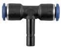
85350-05-535/16(8)-5/32(4) .531(13,5).236(6)2.873(73).866(22).531(13,5).551(14).472(12).130(3,3)
85350-05-535/16(8)-1/4 .531(13,5).236(6)2.873(73).886(22,5).531(13,5).551(14).492(12,5).130(3,3)
85350-05-533/8-1/4 .591(15).276(7)3.267(83).946(24).590(15).669(17).551(14).130(3,3)
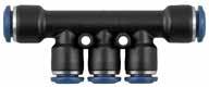

85350-05-533/8-5/16(8) .591(15).276(7)3.267(83).906(23).590(15).669(17).551(14).130(3,3)
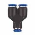
5.9 8 5 Serie s 85240 TEE PLUG IN 85310 UNION Y 85330 4 POSITION Y 85350 REDUCTION MANIFOLD Part No. TubeA BL1L2CHD 85240-53-53 5/32 (4)5/32 (4) .669(17)1.299(33).815(20,7).276(7).394(10) 85240-53-04 5/32 (4) 1/4 .748(19)1.299(33).886(22,5).276(7).394(10) 85240-04-531/4 5/32 (4) .669(17)1.614(41).846(21,5).354(9).492(12,5) 85240-04-041/41/4 .748(19)1.614(41).933(23,7).354(9).492(12,5) 85240-05-05 5/16 (8)5/16 (8) .787(20)1.732(44)1.024(26).394(10).551(14) 85240-05-06 5/16 (8) 3/8 .886(22,5)1.732(44)1.102(28).394(10).551(14) 85240-063/83/8 .886(22,5)2.087(53)1.181(30).512(13).669(17) 85240-53-083/81/2 .983(25)2.087(53)1.259(32).512(13).669(17) 85240-08-081/21/2 1.003(25,5)2.422(61,5)1.319(33,5).629(16).787(20) L1 A D B L2 CH Part No. TubeTube L1ACHD 85310-53-53 5/32 (4)5/32 (4) 1.240(31,5).433(11).393(10).393(10) 85310-04-531/4 5/32 (4) .532(13,5)1.437(36,5).472(12).492(12,5) 85310-04-041/41/4 1.456(37).531(13,5).472(12).492(12,5) 85310-05-04 5/16 (8) 1/4 .610(15,5)1.614(41).551(14).551(14) 85310-05-05 5/16 (8)5/16 (8) 1.574(40).610(15,5).551(14).551(14) 85310-06-063/83/8 1.909(48,5).748(19).669(17).708(18) 85310-08-051/2 5/16 (8) .866(22)2.263(57,5).787(20).787(20) 85310-08-081/21/2 2.322(59).866(22).787(20).787(20) A D D L CH D Part No. D1D2 CLFH 85330-53-53 5/32 (4)5/32 (4) .425(10,8)1.319(33,5).130(3,3).846(21,5) 85330-53-04 5/32 (4) 1/4 .433(11)1.359(34,5).130(3,3).846(21,5) 85330-04-041/41/4 .531(13,5)1.555(39,5).130(3,3)1.064(27) 85330-04-051/4 5/16 (8) .531(13,5)1.575(40).130(3,3)1.064(27) D1 F D2 L H F C Part No. Tube ABL1L2CD1D2E 85350-05-531/4-5/32(4)
A L2 E C B A D2 D1 L1 Page 71
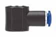
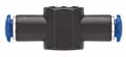


5.10 8 5 Serie s
BANJO BODY
BANJO BODY
BANJO BODY
PLUG Part No. TubeA BLCHD 85500-02-M61/8 M6 .551(14).807(20,5).354(9).394(10) 85500-02-021/81/8 .649(16,5).807(20,5).551(14).394(10) 85500-53-M5 5/32 (4) M5 .551(14).767(19.5).354(9).394(10) 85500-53-M6 5/32 (4) M6 .551(14).767(19.5).354(9).394(10) 85500-53-02 5/32 (4) 1/8 .649(16,5).846(21,5).551(14).394(10) 85500-53-04 5/32 (4) 1/4 .728(18,5).925(23,5).708(18).394(10) 85500-04-M51/4M5 .551(14).826(21).354(9).472(12) 85500-04-M61/4M6 .551(14).826(21).354(9).472(12) 85500-04-021/41/8 .649(16,5).905(23).551(14).472(12) 85500-04-041/41/4 .728(18,5)1.003(25,5).708(18).472(12) 85500-05-02 5/16 (8) 1/8 .649(16,5).925(23,5).551(14).551(14) 85500-05-04 5/16 (8) 1/4 .728(18,5)1.023(26).708(18).551(14) 85500-05-3/8 5/16 (8) 3/8 .866(22)1.082(27,5).826(21).551(14) 85500-06-043/81/4 .728(18,5)1.221(31).708(18).669(17) 85500-06-063/83/8 .866(22)1.200(30,5).826(21).669(17) 85500-08-061/23/8 .866(22)1.279(32,5).826(21).787(20) 85500-08-081/21/2 1.023(26)1.377(35)1.023(26).787(20) ForBANJOSTEMassembliessee10.7/10.8/10.9 A B D L CH Part No. TubeA BLCHD 85510-53-M5 5/32 (4) M5 .551(14)1.535(39).354(9).394(10) 85510-53-02 5/32 (4) 1/8 .649(16,5)1.692(43).551(14).394(10) 85510-04-021/41/8 .649(16,5)1.811(46).551(14).472(12) 85510-04-041/41/4 .728(18,5)2.007(51).708(18).472(12) 85510-05-02 5/16 (8) 1/8 .649(16,5)1.850(47).551(14).551(14) 85510-05-04 5/16 (8) 1/4 .728(18,5)2.047(52).708(18).551(14) ForBANJOSTEMassembliessee10.7/10.8/10.9 A B D L CH Part No. TubeA BCLD 85520-4-1/8 5/32 (4) 1/8 .650(16,5).512(13).827(21).472(12) 85520-4-1/4 5/32 (4) 1/4 .728(18,5).610(15,5).945(24).551(14) 85520-1/4-1/81/41/8 .650(16,5).512(13).846(21,5).492(12,5) 85520-1/4-1/41/41/4 .728(18,5).610(15,5).965(24,5).551(14) 85520-1/4-3/81/43/8 .866(22).531(13,5).984(25).492(12,5) 85520-8-1/4 5/16 (8) 1/4 .728(18,5).610(15,5).965(24,5).551(14) 85520-8-3/8 5/16 (8) 3/8 .866(22).748(19)1.102(28).669(17) 85520-3/8-3/83/83/8 .866(22).748(19)1.102(28).669(17) ForBANJOSTEMassembliessee10.7/10.8/10.9 B L D A C Part No. Tube DL 85620-4 5/32 (4) .393(10).708(18) 85620-1/41/4 .492(12,5).787(20) 85620-8 5/16 (8) .551(14).846(21,5) 85620-3/83/8 .669(17).984(25) 85620-081/2 .787(20)1.082(27,5) D L Page 72
85500 SINGLE
85510 DOUBLE
85520 DOUBLE
85620 TERMINAL
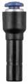
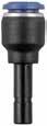
5.11 8 5 Serie s 85700 TUBE REDUCER 85705 TUBE EXPANDER 88610B NYLON PLUG Part No. AB LD 85700-04-531/4 5/32 (4) 1.339(34).394(10) 85700-05-53 5/16 (8)5/32 (4) 1.496(38).472(12) 85700-05-04 5/16 (8) 1/4 1.535(39).492(12,5) 85700-06-043/81/4 1.673(42,5).492(12,5) 85700-06-053/8 5/16 (8) 1.654(42).551(14) 85700-08-041/21/4 1.516(38,5).492(12,5) 85700-08-051/2 5/16 (8) 1.634(41,5).551(14) 85700-08-061/23/8 1.909(48,5).669(17) B L A D Part No. AB LD 85705-53-04 5/32 (4) 1/4 1.417(36).472(12) 85705-04-051/4 5/16 (8) 1.516(38,5).551(14) 85705-04-061/43/8 1.654(42).669(17) 85705-05-06 5/16 (8) 3/8 1.693(43).669(17) 85705-06-083/81/2 1.89(48).787(20) D A L B Part No. Tube L 88610B-021/8 .708(18) 88610B-53 5/32 (4) .925(23,5) 88610B-041/4 .964(24,5) 88610B-05 5/16 (8) 1.023(26) 88610B-063/8 1.122(28,5) 88610B-081/2 1.122(28,5) L Page 73
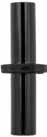
5.12 8 5 Serie s 50980 SECURITY CLIP 55625 DOUBLE JOINT Part No. Tube 50980-4-5/32 5/32 (4) 50980-6-1/4 1/4 (6) 50980-8-5/16 5/16 (8) 50980-10-3/8 3/8 (10) 50980-12-1/2 1/2 (12) Part No. Tube LL1 55625-4 5/32 (4) 1.358(34,5).630(16) 55625-6 1/4 (6) 1.555(39,5).728(18,5) 55625-8 5/16 (8) 1.654(42).768(19,5) 55625-10 3/8 (10) 2.028(51,5).945(24) 55625-12 1/2 (12) 2.362(60)1.102(28) L L1 L1 Page 74
55 Series


56 Series - Mini


Aignep reserves the right to vary models and dimensions without notice


55110 Pg.6.5 55150 Pg.6.10 56010 Pg.6.16 55175 Pg.6.8 55330 Pg.6.13 56230 Pg.6.17 55170 Pg.6.5 55160 Pg.6.11 56020 Pg.6.16 55215 Pg.6.8 55350 Pg.6.13 55210 Pg.6.5 55180 Pg.6.11 56115 Pg.6.16 55225 Pg.6.8 55500 Pg.6.13 55222 Pg.6.6 55230 Pg.6.11 56215 Pg.6.16 55325 Pg.6.9 55510 Pg.6.13 55320 Pg.6.6 55235 Pg.6.11 56225 Pg.6.16 55345 Pg.6.9 55520 Pg.6.14 55340 Pg.6.6 55237 Pg.6.12 56550 Pg.6.17 55365 Pg.6.9 55625 Pg.6.14 55115 Pg.6.7 55310 Pg.6.12 56050 Pg.6.17 55130 Pg.6.10 55705 Pg.6.14 55360 Pg.6.6 55240 Pg.6.12 56040 Pg.6.17 55040 Pg.6.9 55050 Pg.6.10 55700 Pg.6.14 55125 Pg.6.7 55315 Pg.6.12 56130 Pg.6.17 55140 Pg.6.10
STRAIGHT FITTINGS see 50N series 50980 Pg.6.15 50610 Pg.6.15 50615 Pg.6.15 55620 Pg.6.14 55006 Pg.6.15 55991 Pg.6.15 55060 Pg.6.10 50000N Pg.4.5 50010N Pg.4.5 50020N Pg.4.7 50010N Pg.4.6 55106 Pg.6.7 Page 75
For
NYLON PUSH-TO-CONNECT FITTINGS FOR METRIC TUBE
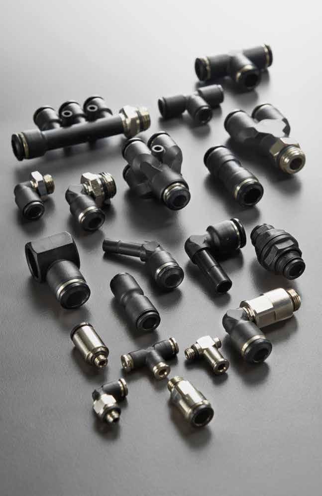
55-56 Series
55000 56000 Page 76
Reference Standard
TECHNICAL CHARACTERISTICS
Bar
Pressure Rating
Vacuum ~ 290 PSI
-0.99 bar ~ 20 bar
-0.099 MPa ~ 2.0 MPa
Media
Compressed air
• Vacuum
• Water
Applications
• Pneumatic Automation
• Automotive
• Textile, Packaging
• Compressed Air Circuit Vacuum
Advantages
1 The 303 Stainless Steel gripper ensures a tight clamp for tubes of any material without damaging the tube’s surface. The secure connection between the tube and the fitting will hold up to severe conditions such as impact and vibrations.
2 The shape of the safety ring and the molded seal perfectly seal off the tube, creating a vacuum.
3 Series with several types of threads: SWIFTFIT BSPP
4 All straight fittings can be tightened with an Allen wrench because of our internal hex design. This enables the end user to tighten the fitting in spaces too small for an openend wrench.
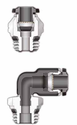
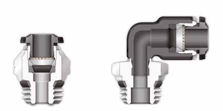
Component Parts and Materials
1 Composite Release Collet
2 Nylon Body
3 NBR Thread Seal
4 Nickel Plated Brass Sleeve
5 303 Stainless Steel Gripper
6 Technopolymer Safety Ring
7 NBR Molded Seal
8 Nickel Plated Thread Brass Body
9 NBR Seal
Tubing Compatibility
Nylon 6 - 11 -12
Polyethylene
Polyurethane (“98 Shore A for best result)
PTFE FEP
6.3 55 Serie s 1907/2006 2011/65/CE ISO 14743:2004 SILICON FREE PED 2014/68/UE
NBR -4º F ~ 176º F -20º C ~ 80º C Temperatures Rating 1 2 3 4 5 6 7 9 8 1 3 4 2 8 Page 77
THREADS & ADVANTAGES
The SWIFTFIT Universal Thread has been designed to offer the following advantages to the end users:
• Reduced overall length
• Smaller hex dimensions compared to parallel threads
• Fits with various parallel and tapered threads
All SWIFTFIT fittings have been equipped with threads and an NBR thread seal that will universally connect to all thread types.
Our SWIFTFIT universal fittings also work on non-flat surfaces without compromising an air-tight seal.

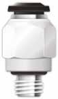
BSPP Threads
The BSPP Thread has been designed to offer the following advantages to the end users:
• Standard ISO 228 and ISO R/262
• Designed for use in BSPP connections with an integrated NBR o-ring that provides a perfect seal
• Completely reusable
6.4 55 Serie s
Torque Specifications Recommended Torque Thread Size Min. Max. 1/8 5 Nm 7 Nm 1/4 5 Nm 7 Nm 3/8 5 Nm 7 Nm 1/2 5 Nm 7 Nm Torque Specifications Recommended Torque Thread Size Min. Breaking Torque M5 0.8 Nm 3.2 Nm M8 3 Nm 8 Nm 1/2 3 Nm 8 Nm 1/4 9 Nm 30 Nm 3/8 10 Nm 60 Nm 1/2 12 Nm 50 Nm NPT NPTF Tapered ISO 228 BSP PF Parallell ISO 7 BSPT PT Tapered ISO 7 BSPP Parallell
Inclined Concave Convex Page 78
One fitting... Endless possibilities
.295(7,5).807(20,5).787(20).354(9).669(17).472(12)
55110-10-3/8103/8 .295(7,5)1043(26,5).858(21,8).512(13).669(17).669(17)
55110-10-1/2101/2 .354(9)1043(26,5).957(24,3).512(13).827(21).669(17)
55110-12-1/4121/4 .276(7)1181(30).909(23,1).630(16).630(16).787(20)
55110-12-3/8123/8 .295(7,5)1181(30).909(23,1).630(16).669(17).787(20)
55110-12-1/2121/2 .354(9)1181(30)1008(25,6).630(16).827(21).787(20)
55110-14-3/8143/8 .295(7,5)1220(31)1043(26,5).709(18).787(20).827(21)
55110-14-1/2141/2 .354(9)1220(31)1063(27).709(18).827(21).827(21)
55170-6-1/861/8 .217(5,5).807(20,5).689(17,5).354(9).512(13).472(12)
55170-6-1/461/4 .276(7).807(20,5).744(18,9).354(9).591(15).472(12) 55170-8-1/8
.217(5,5).866(22).728(18,5).394(10).512(13).551(14) 55170-8-1/4
55170-10-3/8103/8 .295(7,5)1043(26,5).957(24,3).512(13).669(17).669(17)
55170-10-1/2101/2 .354(9)1043(26,5).909(23,1).512(13).827(21).669(17)
55170-12-1/4121/4 .276(7)1181(30).909(23,1).630(16).630(16).787(20)
55170-12-3/8123/8 .295(7,5)1181(30)1008(25,6).630(16).669(17).787(20)
55170-12-1/2121/2 .354(9)1181(30).858(21,8).630(16).827(21).787(20)
55210-8-1/4
55210-8-3/8
.217(5,5)1.614(41).787(20).354(9).512(13).492(12,5)
.276(7)1.732(44).894(22,7).394(10).591(15).551(14)
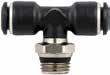
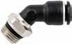

.295(7,5)1.732(44).913(23,2).394(10).669(17).551(14)
55210-10-1/4101/4 .276(7)2.087(53)1.012(25,7).512(13).630(16).669(17)
55210-10-3/8103/8 .295(7,5)2.087(53)1.012(25,7).512(13).669(17).669(17)
55210-10-1/2101/2 .354(9)2.087(53)1.11(28,2).512(13).827(21).669(17)
55210-12-1/4121/4 .276(7)2.362(60)1.067(27,1).630(16).630(16).787(20)
55210-12-3/8123/8 .295(7,5)2.362(60)1.067(27,1).630(16).669(17).787(20)
55210-12-1/2121/2 .354(9)2.362(60)1.165(29,6).630(16).827(21).787(20)
55210-14-3/8143/8 .295(7,5)2.402(61)1.189(30,2).709(18).787(20).827(21)
55210-14-1/2141/2 .354(9)2.402(61)1.209(30,7).709(18).827(21).827(21)
6.5 55 Serie s 55110 SWIVEL ELBOW 55170 45° SWIVEL ELBOW 55210 SWIVEL BRANCH TEE Part No. TubeA BL1L2CH1CH2D 55110-4-1/8 5/32 (4) 1/8 .217(5,5).650(16,5).650(16,5).276(7).512(13).394(10) 55110-4-1/4 5/32 (4) 1/4 .276(7).650(16,5).709(18).276(7).591(15).394(10)
55110-8-1/8 5/16 (8) 1/8 .217(5,5).866(22).728(18,5).394(10).512(13).551(14) 55110-8-1/4 5/16 (8) 1/4 .276(7).866(22).787(20).394(10).591(15).551(14) 55110-8-3/8 5/16 (8) 3/8 .295(7,5).866(22).807(20,5).394(10).669(17).551(14) 55110-8-1/2 5/16 (8) 1/2 .354(9).866(22).906(23).394(10).827(21).551(14) 55110-10-1/4101/4 .276(7)1043(26,5).858(21,8).512(13).630(16).669(17)
55110-5-1/851/8 .217(5,5).787(20).685(17,4).354(9).512(13).472(12) 55110-6-1/861/8 .217(5,5).807(20,5).685(17,4).354(9).512(13).472(12) 55110-6-1/461/4 .276(7).807(20,5).744(18,9).354(9).591(15).472(12) 55110-6-3/863/8
55110-6-1/261/2 .354(9).807(20,5).866(22).354(9).827(21).472(12)
CH1 CH2 L1 A B D L2 Part No. TubeA BL1L2CH1CH2D 55170-4-1/8 5/32 (4) 1/8
.217(5,5).492(12,5).650(16,5).276(7).512(13).394(10)
5/16
1/8
5/16 (8) 1/4 .276(7).866(22).787(20).394(10).591(15).551(14) 55170-8-3/8 5/16 (8) 3/8 .295(7,5).866(22).807(20,5).394(10).669(17).551(14) 55170-10-1/4101/4 .276(7)1043(26,5).858(21,8).512(13).630(16).669(17)
(8)
D L2 L1 A B CH1 CH2 Part No. TubeA BL1L2CH1CH2D 55210-4-1/8 5/32 (4) 1/8 .217(5,5)1.299(33).736(18,7).276(7).512(13).394(10) 55210-4-1/4 5/32 (4) 1/4 .276(7)1.299(33).795(20,2).276(7).591(15).394(10) 55210-5-1/851/8 .217(5,5)1.575(40).787(20).354(9).512(13).472(12) 55210-6-1/861/8
55210-6-1/461/4
55210-8-1/8 5/32 (8) 1/8
.276(7)1.614(41).846(21,5).354(9).591(15).492(12,5)
.217(5,5)1.732(44).835(21,2).394(10).512(13).551(14)
5/32 (8) 1/4
5/32 (8) 3/8
CH2 CH1 B A L2 L1 D Page 79
55360-6-4-1/46-5/32(4) 1/4 .531(13,5).236(6)2.811(71,4).858(21,8).531(13,5).130(3,3).276(7).591(15).551(14).472(12)
55360-8-4-1/85/16(8)-5/32(4) 1/8 .531(13,5).236(6)2.756(70).858(21,8).531(13,5).130(3,3).217(5,5).512(13).551(14).472(12)
55360-8-4-1/45/16(8)-5/32(4) 1/4 .531(13,5).236(6)2.811(71,4).858(21,8).531(13,5).130(3,3).276(7).591(15).551(14).472(12)
55360-8-6-1/85/16(8)-6 1/8 .531(13,5).236(6)2.756(70).878(22,3).531(13,5).130(3,3).217(5,5).512(13).551(14).492(12,5)
55360-8-6-1/45/16(8)-6 1/4 .531(13,5).236(6)2.811(71,4).878(22,3).531(13,5).130(3,3).276(7).591(15).551(14).492(12,5)
55360-10-6-1/410-6 1/4 .591(15).276(7)3.209(81,5).933(23,7).591(15).130(3,3).276(7).630(16).669(17).551(14)
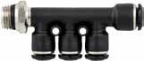
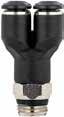
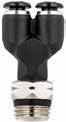

55360-10-6-3/810-6 3/8 .591(15).276(7)3.209(81,5).933(23,7).591(15).130(3,3).295(7,5).669(17).669(17).551(14)
55360-10-8-1/410-5/16(8) 1/4 .591(15).276(7)3.209(81,5).913(23,2).591(15).130(3,3).276(7).630(16).669(17).551(14)
55360-10-8-3/810-5/16(8) 3/8 .591(15).276(7)3.209(81,5).913(23,2).591(15).130(3,3).295(7,5).669(17).669(17).551(14)
6.6 55 Serie s 55222 SWIVEL RUN TEE 55320 UNION Y 55340 4 POSITION Y 55360 REDUCTION MANIFOLD Part No. TubeA BL1L2CH1CH2D 55222-4-1/8 5/32 (4) 1/8 .217(5,5).650(16,5).717(18,2).276(7).512(13).394(10) 55222-4-1/8 5/32 (4) 1/4 .276(7).650(16,5).776(19,7).276(7).591(15).394(10) 55222-5-1/851/8 .217(5,5).787(20).685(17,4).354(9).512(13).472(12) 55222-6-1/861/8 .217(5,5).807(20,5).685(17,4).354(9).512(13).492(12,5) 55222-6-1/461/4 .276(7).807(20,5).744(18,9).354(9).591(15).492(12,5) 55222-8-1/8 5/16 (8) 1/8 .217(5,5).866(22).744(18,9).394(10).512(13).551(14) 55222-8-1/4 5/16 (8) 1/4 .276(7).866(22).803(20,4).394(10).591(15).551(14) 55222-8-3/8 5/16 (8) 3/8 .295(7,5).866(22).823(20,9).394(10).669(17).551(14) 55222-10-1/4101/4 .276(7)1.043(26,5).858(21,8).512(13).630(16).669(17) 55222-10-3/8103/8 .295(7,5)1.043(26,5).858(21,8).512(13).669(17).669(17) 55222-10-1/2101/2 .354(9)1.043(26,5).957(24,3).512(13).827(21).669(17) 55222-12-1/4121/4 .276(7)1.220(31).909(23,1).630(16).630(16).787(20) 55222-12-3/8123/8 .295(7,5)1.220(31).909(23,1).630(16).669(17).787(20) 55222-12-1/2121/2 .354(9)1.220(31)1.008(25,6).630(16).827(21).787(20) 55222-14-3/8143/8 .295(7,5)1.201(30,5)1.043(26,5).709(18).787(20).827(21) 55222-14-1/2141/2 .354(9)1.201(30,5)1.063(27).709(18).827(21).827(21) CH1 CH2 A D L1 L1 L2 B Part No. TubeA BCLCH1CH2 55320-4-1/8 5/32 (4) 1/8 .217(5,5).433(11)1.496(38).394(10).433(11) 55320-4-1/4 5/32 (4) 1/4 .276(7).433(11)1.594(40,5).394(10).551(14) 55320-6-1/861/8 .217(5,5).531(13,5)1.693(43).472(12).433(11) 55320-6-1/461/4 .276(7).531(13,5)1.791(45,5).472(12).551(14) 55320-8-1/8 5/16 (8) 1/8 .217(5,5).610(15,5)1.831(46,5).551(14).433(11) 55320-8-1/4 5/16 (8) 1/4 .276(7).610(15,5)1.929(49).551(14).551(14) 55320-8-3/8 5/16 (8) 3/8 .295(7,5).610(15,5)1.949(49,5).551(14).669(17) 55320-10-1/4101/4 .276(7).748(19)2.224(56,5).669(17).551(14) 55320-10-3/8103/8 .295(7,5).748(19)2.264(57,5).669(17).669(17) 55320-10-1/2101/2 .354(9).748(19)2.362(60).669(17).827(21) 55320-12-3/8123/8 .295(7,5).866(22)2.618(66,5).787(20).669(17) 55320-12-1/2121/2 .354(9).866(22)2.677(68).787(20).827(21) A C CH1 L B CH2 Part No. TubeA BCLHCHF 55340-4-1/8 5/32 (4) 1/8 .217(5,5).425(10,8)1.555(39,5).846(21,5).433(11).130(3,3) 55340-4-1/4 5/32 (4) 1/4 .276(7).425(10,8)1.654(42).846(21,5).551(14).130(3,3) 55340-6-1/861/8 .217(5,5).524(13,3)1.831(46,5)1.055(26,8).433(11).130(3,3) 55340-6-1/461/4 .276(7).524(13,3)1.890(48)1.055(26,8).551(14).130(3,3) A L H F C CH B F Part No. TubeF ABL1L2CEGHD1D2 55360-6-4-1/86-5/32(4) 1/8 .531(13,5).236(6)2.756(70).858(21,8).531(13,5).130(3,3).217(5,5).512(13).551(14).472(12)
A L2 E C B A D2 D1 L1 F CH G Page 80
55115
SWIVEL ELBOW
55106
ORIENTING ELBOW FEMALE ADAPTOR
55125
EXTENDED SWIVEL ELBOW
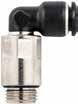
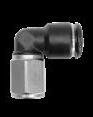

L2
55115-5-1/851/8 .213(5,4).787(20).622(15,8).354(9).512(13).472(12)
55115-6-M56M5 .142(3,6).807(20,5).579(14,7).354(9).354(9).472(12)
55115-6-M76M7 .196(5).807(20,5).610(15,5).354(9).354(9).492(12.5)
55115-6-M10x16M10x1 .216(5.5).807(20,5).610(15,5).512(13).354(9).492(12.5)
55115-6-M12x16M12x1 .276(7).807(20,5).689(18).630(16).354(9).492(12.5)
55115-6-1/861/8 .213(5,4).807(20,5).622(15,8).354(9).512(13).472(12)
55115-6-1/461/4 .280(7,1).807(20,5).689(17,5).354(9).630(16).472(12)
55115-6-3/863/8 .319(8,1).807(20,5).748(19).354(9).787(20).472(12)
55115-6-1/261/2 .378(9,6).807(20,5).827(21).354(9).984(25).472(12)
55115-8-M10x18M10x1 .216(5.5).886(22,5).768(19,5).512(13).394(10).551(14)
55115--M12x18M12x1 .296(7,5).886(22,5).748(19).630(16).394(10).551(14)
55115-8-1/8
.280(7,1).866(22).736(18,7).394(10).630(16).551(14)
.213(5,4).866(22).764(19,4).394(10).512(13).551(14) 55115-8-1/4
.378(9,6).866(22).870(22,1).394(10).984(25).551(14)
55115-10-1/8101/8 .216(5.5)1043(26,5).827(21).630(16).512(13).669(17)
55115-10-1/4101/4 .280(7,1)1043(26,5).898(22,8).512(13).630(16).669(17)
55115-10-3/8103/8 .319(8,1)1043(26,5).878(22,3).512(13).787(20).669(17)
55115-10-1/2101/2 .378(9,6)1043(26,5).937(23,8).512(13).984(25).669(17)
55115-12-1/4121/4 .280(7,1)1181(30).949(24,1).630(16).630(16).787(20)
55115-12-3/8123/8 .319(8,1)1181(30).929(23,6).630(16).787(20).787(20)
55115-12-1/2121/2 .378(9,6)1181(30).988(25,1).630(16).984(25).787(20)
55115-14-3/8143/8 .319(8,1)1220(31)1106(28,1).709(18).787(20).827(21)
55115-14-1/2141/2 .378(9,6)1220(31)1028(26,1).709(18).984(25).827(21)
BSPP B
D
.213(5,4).886(22,5)1.358(34,5).394(10).472(12).551(14)
55125-6-1/861/8 .213(5,4).807(20,5)1.161(29,5).354(9).472(12).492(12,5) 55125-8-1/8
55125-8-3/8
.280(7,1).886(22,5)1.319(33,5).394(10).591(15).551(14)
.312(8,1).886(22,5)1.358(34,5).393(10).472(12).551(14)
55125-10-1/4101/4 .279(7,1)1.043(26,5)1.693(43).512(13).590(15).669(17)
55125-10-3/8103/8 .312(8,1)1.043(26,5)1.693(43).512(13).590(15).669(17)
55125-10-1/2101/2 .378(9,6)1.043(26,5)1.771(45).512(13).590(15).669(17)
55125-12-1/4121/4 .279(7,1)1.220(31)1.771(45).630(16).590(15).787(20)
55125-12-3/8123/8 .312(8,1)1.200(30,5)1.752(44,5).630(16).590(15).787(20)
L1 CH1 CH2 Page 81
6.7 55 Serie s
Part No. TubeA BL1L2CH1CH2D 55115-4-M5 5/32 (4) M5 .142(3,6).650(16,5).543(13,8).276(7).354(9).394(10) 55115-4-M7X1 5/32 (4) M7X1 .189(4,8).650(16,5).567(14,4).276(7).354(9).394(10) 55115-4-1/8 5/32 (4) 1/8 .213(5,4).650(16,5).591(15).276(7).512(13).394(10) 55115-4-1/4 5/32 (4) 1/4 .280(7,1).650(16,5).654(16,6).354(9).630(16).394(10) 55115-4-3/8 5/32 (4) 3/8 .216(5.5).650(16,5).709(18).787(20).280(7).394(10) 55115-5-M55M5
.142(3,6).787(20).579(14,7).354(9).354(9).472(12)
5/16 (8) 1/8
5/16 (8) 1/4
55115-8-3/8 5/16 (8) 3/8
5/16 (8) 1/2
.319(8,1).866(22).791(20,1).394(10).787(20).551(14) 55115-8-1/2
BSPP CH2 CH1 A L2 B L1 D Part No. TubeA BL1L2CH1CH2D 55106-4-1/8 5/32 (4) 1/8 .335(8,5).650(16,5).748(19).276(7).492(12,5).394(10) 55106-4-1/4 5/32 (4) 1/4 .433(11).650(16,5).886(22,5).276(7).630(16).394(10) 55106-6-1/86 1/8 .335(8,5).807(20,5).787(20).354(9).512(13).492(12,5) 55106-6-1/46 1/4 .433(11).807(20,5).925(23,5).354(9).630(16).492(12,5) 55106-8-1/8 5/16 (8) 1/8 .335(8,5).886(22,5).827(21).394(10).512(13).552(14) 55106-8-1/4 5/16 (8) 1/4 .433(11).886(22,5).925(23,5).394(10).630(16).552(14) 55106-8-3/8 5/16 (8) 3/8 .472(12).886(22,5).965(24,5).394(10).748(19).552(14) 55106-10-1/410 1/4 .433(11)1.043(26,5)1.063(27).512(13).630(16).669(17) 55106-10-3/810 3/8 .472(12)1.043(26,5)1.063(27).512(13).748(19).669(17) BSPP D L2 L1 B A CH2 CH1 Part No. TubeA BL1L2CH1CH2D 55125-4-M5 5/32 (4) M5
55125-4-1/8 5/32 (4) 1/8
55125-6-M56M5
.142(3,6).650(16,5)1.083(27,5).276(7).315(8).394(10)
.213(5,4).650(16,5)1.122(28,5).276(7).472(12).394(10)
.142(3,6).807(20,5)1.161(29,5).354(9).315(8).492(12,5)
5/16 (8) 1/8
5/16 (8) 1/4
55125-8-1/4
5/16 (8) 3/8
55125-12-1/2121/2 .378(9,6)1.220(31)1.811(46).630(16).590(15).787(20) A
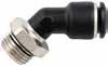
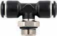
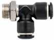
6.8 55 Serie s 55175 45° SWIVEL ELBOW 55215 SWIVEL BRANCH TEE 55225 SWIVEL RUN TEE Part No. TubeA BL1L2CH1CH2D 55175-4-M5 5/32 (4) M5 .142(3,6).492(12,5).543(13,8).276(7).354(9).394(10) 55175-4-1/8 5/32 (4) 1/8 .213(5,4).492(12,5).591(15).276(7).512(13).394(10) 55175-6-M56M5 .142(3,6).807(20,5).579(14,7).354(9).354(9).472(12) 55175-6-1/861/8 .213(5,4).807(20,5).622(15,8).354(9).512(13).472(12) 55175-6-1/461/4 .280(7,1).807(20,5).689(17,5).354(9).630(16).472(12) 55175-8-1/8 5/16 (8) 1/8 .213(5,4).866(22).764(19,4).394(10).512(13).551(14) 55175-8-1/4 5/16 (8) 1/4 .280(7,1).866(22).736(18,7).394(10).630(16).551(14) 55175-8-3/8 5/16 (8) 3/8 .319(8,1).866(22).791(20,1).394(10).787(20).551(14) 55175-10-1/4101/4 .280(7,1)1.043(26,5).898(22,8).512(13).630(16).669(17) 55175-10-3/8103/8 .319(8,1)1.043(26,5).878(22,3).512(13).787(20).669(17) 55175-10-1/2101/2 .378(9,6)1.043(26,5).937(23,8).512(13).984(25).669(17) 55175-12-1/4121/4 .280(7,1)1.181(30).949(24,1).630(16).630(16).787(20) 55175-12-3/8123/8 .319(8,1)1.181(30).929(23,6).630(16).787(20).787(20) 55175-12-1/2121/2 .378(9,6)1.181(30).988(25,1).630(16).984(25).787(20) BSPP D B L2 L1 A CH CH2 Part No. TubeA BL1L2CH1CH2D 55215-4-M5 5/32 (4) M5 .142(3,6)1.299(33).610(15,5).276(7).354(9).394(10) 55215-4-1/8 5/32 (4) 1/8 .213(5,4)1.299(33).673(17,1).276(7).512(13).394(10) 55215-4-1/4 5/32 (4) 1/4 .280(7,1)1.299(33).740(18,8).276(7).630(16).394(10) 55215-5-M55M5 .142(3,6)1.575(40).579(14,7).354(9).354(9).472(12) 55215-5-1/851/8 .213(5,4)1.575(40).724(18,4).354(9).512(13).472(12) 55215-6-M56M5 .142(3,6)1.614(41).579(14,7).354(9).354(9).492(12,5) 55215-6-1/861/8 .213(5,4)1.614(41).724(18,4).354(9).512(13).492(12,5) 55215-6-1/461/4 .280(7,1)1.614(41).787(20).354(9).630(16).492(12,5) 55215-8-1/8 5/16 (8) 1/8 .213(5,4)1.732(44).870(22,1).394(10).512(13).551(14) 55215-8-1/4 5/16 (8) 1/4 .280(7,1)1.732(44).843(21,4).394(10).630(16).551(14) 55215-8-3/8 5/16 (8) 3/8 .319(8,1)1.732(44).898(22,8).394(10).787(20).551(14) 55215-10-1/4101/4 .280(7,1)2.087(53)1.051(26,7).512(13).630(16).669(17) 55215-10-3/8103/8 .319(8,1)2.087(53)1.031(26,2).512(13).787(20).669(17) 55215-10-1/2101/2 .378(9,6)2.087(53)1.091(27,7).512(13).984(25).669(17) 55215-12-1/4121/4 .280(7,1)2.421(61,5)1.106(28,1).630(16).630(16).787(20) 55215-12-3/8123/8 .319(8,1)2.421(61,5)1.087(27,6).630(16).787(20).787(20) 55215-12-1/2121/2 .378(9,6)2.421(61,5)1.146(29,1).630(16).984(25).787(20) 55215-14-3/8143/8 .319(8,1)2.402(61)1.252(31,8).709(18).787(20).827(21) 55215-14-1/2141/2 .378(9,6)2.402(61)1.173(29,8).709(18).984(25).827(21) BSPP CH1 CH2 B A L2 D L1 Part No. TubeA BL1L2CH1CH2D 55225-4-M5 5/32 (4) M5 .142(3,6)16.515.57.354(9)10 55225-4-1/8 5/32 (4) 1/8 .217(5,5).650(16,5).717(18,2).276(7).512(13).394(10) 55225-4-1/4 5/32 (4) 1/4 .276(7).650(16,5).776(19,7).276(7).591(15).394(10) 55225-5-M55M5 .142(3,6).787(20).571(14,5).354(9).354(9).472(12) 55225-5-1/851/8 .217(5,5).787(20).685(17,4).354(9).512(13).472(12) 55225-6-M56M5 .142(3,6).807(20,5).571(14,5).354(9).354(9).492(12,5) 55225-6-1/861/8 .217(5,5).807(20,5).685(17,4).354(9).512(13).492(12,5) 55225-6-1/461/4 .276(7).807(20,5).744(18,9).354(9).591(15).492(12,5) 55225-8-1/8 5/16 (8) 1/8 .217(5,5).866(22).744(18,9).394(10).512(13).551(14) 55225-8-1/4 5/16 (8) 1/4 .276(7).866(22).803(20,4).394(10).591(15).551(14) 55225-8-3/8 5/16 (8) 3/8 .295(7,5).866(22).823(20,9).394(10).669(17).551(14) 55225-10-1/4101/4 .276(7)1.043(26,5).858(21,8).512(13).630(16).669(17) 55225-10-3/8103/8 .295(7,5)1.043(26,5).858(21,8).512(13).669(17).669(17) 55225-10-1/2101/2 .354(9)1.043(26,5).957(24,3).512(13).827(21).669(17) 55225-12-1/4121/4 .276(7)1.220(31).909(23,1).630(16).630(16).787(20) 55225-12-3/8123/8 .296(7,5)1.220(31).909(23,1).630(16).669(17).787(20) 55225-12-1/2121/2 .354(9)1.220(31)1.008(25,6).630(16).827(21).787(20) 55225-14-3/8143/8 .295(7,5)1.201(30,5)1.043(26,5).709(18).787(20).827(21) 55225-14-1/2141/2 .354(9)1.201(30,5)1.063(27).709(18).827(21).827(21) BSPP CH1 CH2 L2 L1 D L1 A B Page 82
BSPP B
55325-10-3/8103/8 .354(9).748(19)2.343(59,5).669(17).787(20) 55325-10-1/2101/2 .394(10).748(19)2.441(62).669(17).945(24)
55325-12-3/8123/8 .354(9).866(22)2.697(68,5).787(20).787(20)
55040-1212
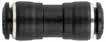
55040-12-812
.236(6).524(13,3)1.850(47)1.055(26,8).512(13).130(3,3)
.315(8).524(13,3)1.929(49)1.055(26,8).630(16).130(3,3)
.315(8).425(10,8)1.654(42).846(21,5).630(16).130(3,3) L Page 83
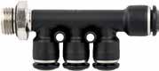
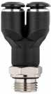
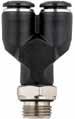
6.9 55 Serie s 55325 UNION Y 55345 4 POSITION Y 55365 REDUCTION MANIFOLD 55040 UNION Part No. TubeA BCLCH1CH2 55325-4-M5 5/32 (4) M5 .157(4).433(11)1.437(36,5).394(10).394(10) 55325-4-1/8 5/32 (4) 1/8 .236(6).433(11)1.516(38,5).394(10).512(13) 55325-4-1/4 5/32 (4) 1/4 .315(8).433(11)1.594(40,5).394(10).630(16) 55325-6-M56M5 .157(4).531(13,5)1.634(41,5).472(12).394(10) 55325-6-1/861/8 .236(6).531(13,5)1.713(43,5).472(12).512(13) 55325-6-1/461/4 .315(8).531(13,5)1.831(46,5).472(12).630(16) 55325-8-1/8 5/16 (8) 1/8 .236(6).610(15,5)1.850(47).551(14).512(13) 55325-8-1/4 5/16 (8) 1/4 .315(8).610(15,5)1.969(50).551(14).630(16) 55325-8-3/8 5/16 (8) 3/8 .354(9).610(15,5)2.047(52).551(14).787(20) 55325-10-1/4101/4 .315(8).748(19)2.343(59,5).669(17).630(16)
A C CH1 L B CH2 Part No. TubeA BCLHCHF 55345-4-1/8 5/32 (4) 1/8 .236(6).425(10,8)1.575(40).846(21,5).512(13).130(3,3) 55345-4-1/4 5/32 (4) 1/4
55345-6-1/861/8
55345-6-1/461/4
BSPP A L H F C CH B F Part No. Tube F ABL1L2CEGHD1D2 55365-6-4-1/8 6-5/32(4) 1/8 .531(13,5).236(6)2.783(70,7).858(21,8).531(13,5).130(3,3).213(5,4).512(13).551(14).472(12) 55365-6-4-1/4 6-5/32(4) 1/4 .531(13,5).236(6)2.756(70).858(21,8).531(13,5).130(3,3).280(7,1).630(16).551(14).472(12) 55365-8-4-1/8 5/16(8)-5/32(4) 1/8 .531(13,5).236(6)2.783(70,7).858(21,8).531(13,5).130(3,3).213(5,4).512(13).551(14).472(12) 55365-8-4-1/4 5/16(8)-5/32(4) 1/4 .531(13,5).236(6)2.756(70).858(21,8).531(13,5).130(3,3).280(7,1).630(16).551(14).472(12) 55365-8-6-1/8 5/16(8)-6 1/8 .531(13,5).236(6)2.783(70,7).878(22,3).531(13,5).130(3,3).213(5,4).512(13).551(14).492(12,5) 55365-8-6-1/4 5/16(8)-6 1/4 .531(13,5).236(6)2.756(70).878(22,3).531(13,5).130(3,3).280(7,1).630(16).551(14).492(12,5) 55365-10-6-1/4 10-6 1/4 .591(15).276(7)3.244(82,4).933(23,7).591(15).130(3,3).280(7,1).630(16).669(17).551(14) 55365-10-6-3/8 10-6 3/8 .591(15).276(7)3.228(82).933(23,7).591(15).130(3,3).319(8,1).787(20).669(17).551(14) 55365-10-8-1/4 10-5/16(8) 1/4 .591(15).276(7)3.244(82,4).913(23,2).591(15).130(3,3).280(7,1).630(16).669(17).551(14) 55365-10-8-3/8 10-5/16(8) 3/8 .591(15).276(7)3.228(82).913(23,2).591(15).130(3,3).319(8,1).787(20).669(17).551(14) BSPP A L2 E C B A D2 D1 L1 F CH G Part No. TubeTube LB 55040-4 5/32 (4) 1.220(31).394(10) 55040-55 1339(34).472(12) 55040-66 1378(35).492(12,5) 55040-6-46 5/32 (4) 1339(34).492(12,5) 55040-8 5/16 (8) 1457(37).551(14) 55040-8-4 5/16 (8)5/32 (4) 1476(37,5).551(14) 55040-8-6 5/16 (8) 6 1476(37,5).551(14) 55040-1010 1772(45).669(17)
1732(44).669(17) 55040-10-810 5/16 (8) 1732(44).669(17)
1929(49).787(20)
5/16 (8) 1929(49).787(20)
1929(49).787(20)
1890(48).827(21)
55325-12-1/2121/2 .394(10).866(22)2.795(71).787(20).945(24) 1909(48,5).827(21)
55040-10-6106
55040-12-101210
55040-1414
55040-14-121412

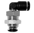


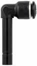
6.10 55 Serie s 55050 BULKHEAD UNION 55060 BULKHEAD ORIENTING ELBOW 55130 UNION ELBOW 55140 ELBOW PLUG IN 55150 ELBOW PLUG IN Part No. Tube MLCHAmax 55050-8 5/16 (8) M16X11.527(38,8).708(18).571(14,5) A max L M CH Part No. Tube M L1L2CHCH1CH2AmaxD 55060-4-M12X1 5/32 (4) M12x1 .650(16,5)1.181(30).276(7).551(14).669(17).256(6,5).394(10) 55060-6-M14x16 M14x1 .807(20,5)1.220(31).354(9).630(16).669(17).256(6,5).472(12) 55060-8-M16x1 5/16 (8) M16x1 .886(22,5)1.339(34).394(10).709(18).748(19).276(7).551(14) 55060-10-M20x110 M20x1 1.043(26,5)1.535(39).512(13).709(18).945(24).296(7,5).669(17) 55060-12-M22x112 M22x1 1.181(30)1.732(44).630(16).985(25)1.024(26).394(9,5).787(20) M L2 L1 D Amax CH CH1 CH2 Part No. D1D2 LCHD 55130-4 5/32 (4) .650(16,5).354(9).394(10) 55130-55 .787(20).433(11).472(12) 55130-66 .807(20,5).433(11).472(12) 55130-8-6 5/16 (8) 6 .886(22,5).512(13).551(14) 55130-8 5/16 (8) .866(22).512(13).551(14) 55130-10-6106 1.024(26).630(16).669(17) 55130-10-810 5/16 (8) 1.024(26).630(16).669(17) 55130-1010 1.043(26,5).630(16).669(17) 55130-12-101210 1.201(30,5).748(19).787(20) 55130-1212 1.181(30).748(19).787(20) 55130-1414 1.201(30,5).787(20).827(21) L D D CH L Part No. TubeA BL1L2CH1D 55140-4 5/32 (4)5/32 (4) .669(17).650(16,5).819(20,8).276(7).394(10) 55140-4-6 5/32 (4) 6 .748(19).650(16,5).898(22,8).276(7).394(10) 55140-666 .748(19).807(20,5).933(23,7).354(9).492(12,5) 55140-6-46 5/32 (4) .669(17).807(20,5).854(21,7).354(9).492(12,5) 55140-6-86 5/16 (8) .787(20).886(22,5)1.024(26).394(10).551(14) 55140-8 5/16 (8)5/16 (8) .787(20).866(22)1.024(26).394(10).551(14) 55140-8-10 5/16 (8) 10 .858(21,8).866(22)1.087(27,6).394(10).551(14) 55140-101010 .886(22,5)1.043(26,5)1.181(30).512(13).669(17) 55140-10-121012 .972(24,7)1.043(26,5)1.268(32,2).512(13).669(17) 55140-121212 1.004(25,5)1.181(30)1.319(33,5).630(16).787(20) L1 A CH1 D B L2 Part No. TubeA BL1L2CH1D 55150-4 5/32 (4)5/32 (4) 1.102(28).650(16,5)1.252(31,8).276(7).394(10) 55150-4-6 5/32 (4) 6 1.201(30,5).650(16,5)1.350(34,3).276(7).394(10) 55150-666 1.272(32,3).807(20,5)1.457(37).354(9).492(12,5) 55150-6-46 5/32 (4) 1.181(30).807(20,5)1.366(34,7).354(9).492(12,5) 55150-8 5/16 (8)5/16 (8) 1.417(36).866(22)1.654(42).394(10).551(14) 55150-8-10 5/16 (8) 10 1.476(37,5).866(22)1.697(43,1).394(10).551(14) 55150-101010 1.606(40,8)1.043(26,5)1.902(48,3).512(13).669(17) 55150-10-121012 1.701(43,2)1.043(26,5)1.996(50,7).512(13).669(17) 55150-121212 1.850(47)1.220(31)2.165(55).630(16).787(20) L1 A CH1 D B L2 Page 84
45° ELBOW PLUG IN
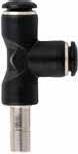
55180
45° UNION ELBOW
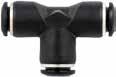
55230
UNION TEE
55235
RUN TEE PLUG IN
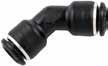
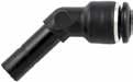
Part No. TubeA BL1L2CH1D
55160-4 5/32 (4)5/32 (4) .669(17).492(12,5).827(21).276(7).394(10)
55160-666 .748(19).807(20,5).925(23,5).354(9).472(12)
55160-8 5/16 (8)5/16 (8) .787(20).866(22).984(25).394(10).551(14)
55160-101010 .886(22,5)1.043(26,5)1.181(30).512(13).669(17)
55160-121212 1.004(25,5)1.181(30)1.319(33,5).630(16).787(20)
Part No. Tube LCHD
55180-4 5/32 (4) .650(16,5).276(7).394(10)
55180-66 .807(20,5).354(9).472(12)
55180-8 5/16 (8) .866(22).394(10).551(14)
55180-1010 1.043(26,5).512(13).669(17)
Part No. D1D2A BLL1L2CHD
5/32(4)5/32(4)5/32(4) .591(15)1.102(28).650(16,5).650(16,5).354(9).394(10)
6.11 55 Serie s
55160
D L1 L2 B A CH
55180-1212 1.181(30).630(16).787(20) L L D CH Part No. D1D2 L1L2CHD 55230-4 5/32(4)5/32(4) 1.299(33).650(16,5).354(9).394(10) 55230-555 1.575(40).787(20).433(11).472(12) 55230-6-465/32(4) 1.575(40).807(20,5).433(11).492(12,5) 55230-666 1.614(41).807(20,5).433(11).472(12) 55230-4-65/32(4)6 1.614(41).787(20).433(11).492(12,5) 55230-8-65/16(8)6 1.772(45).886(22,5).512(13).551(14) 55230-8 5/16(8) 5/16(8) 1.732(44).866(22).512(13).551(14) 55230-6-8 65/16(8) 1.772(45).886(22,5).512(13).551(14) 55230-10-8105/16(8) 2.047(52)1.043(26,5).630(16).669(17) 55230-10 10 10 2.087(53)1.043(26,5).630(16).669(17) 55230-8-105/16(8)10 2.087(53)1.024(26).630(16).669(17) 55230-12-10 12 10 2.343(59,5)1.201(30,5).748(19).787(20) 55230-121212 2.421(61,5)1.181(30).748(19).787(20) 55230-10-121012 2.421(61,5)1.181(30).748(19).787(20) 55230-14 14 14 2.402(61)1.201(30,5).787(20).827(21) 55230-8-145/16(8)14 2.421(61,5)1.161(29,5).787(20).827(21) 55230-10-141014 2.402(61)1.181(30).787(20).827(21) 55230-12-14 12 14 2.402(61)1.201(30,5).787(20).827(21) D1 D2 D2 D L2 L1 CH
55235-6-6-6
5/16(8)5/16(8)5/16(8) .709(18)1.437(36,5).886(22,5).886(22,5).512(13).551(14) 55235-10-10-10 101010 .866(22)1.732(44)1.043(26,5)1.043(26,5).630(16).669(17) 55235-12-12-12 121212 .965(24,5)1.220(31)1.969(50)1.22(31).748(19).787(20) 55235-4-6-6 5/32(4)66 .669(17).787(20)1.319(33,5).807(20,5).433(11).492(12,5) 55235-6-8-8 65/16(8)5/16(8) .886(22,5).886(22,5)1.437(36,5).886(22,5).512(13).551(14) 55235-8-10-10 5/16(8)1010 .866(22)1.024(26)1.732(44)1.043(26,5).630(16).669(17) 55235-10-12-12 101212 .965(24,5)1.181(30)1.969(50)1.22(31).748(19).787(20) A B L1 L2 D1 D L D2 Page 85
55235-4-4-4
666 .669(17)1.319(33,5).807(20,5).807(20,5).433(11).492(12,5) 55235-8-8-8
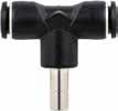
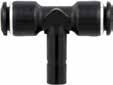
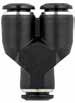
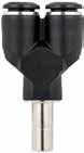
6.12 55 Serie s 55237 BRANCH TEE PLUG IN 55240 TEE PLUG IN 55310 UNION Y 55315 Y PLUG IN Part No. D1A BLL1CHD 55237-6-46 5/32 (4) .591(15)1.240(31,5)1.614(41).433(11).492(12,5) 55237-8-6 5/16 (8) 6 .669(17)1.398(35,5)1.772(45).512(13).551(14) 55237-10-810 5/16 (8) .709(18)1.575(40)2,087(53).630(16).669(17) 55237-12-101210 .866(22)1.870(47,5)2,402(61).748(19).787(20) A D1 D1 L1 B L D CH Part No. TubeA BL1L2CHD 55240-4 5/32 (4)5/32 (4) .669(17)1.299(33).815(20,7).276(7).394(10) 55240-4-6 5/32 (4) 6 .748(19)1.299(33).894(22,7).276(7).394(10) 55240-666 .748(19)1.614(41).933(23,7).354(9).492(12,5) 55240-6-46 5/32 (4) .669(17)1.614(41).854(21,7).354(9).492(12,5) 55240-8 5/16 (8)5/16 (8) .787(20)1.732(44)1.024(26).394(10).551(14) 55240-8-10 5/16 (8) 10 .874(22,2)1.732(44)1.102(28).394(10).551(14) 55240-101010 .886(22,5)2.087(53)1.181(30).512(13).669(17) 55240-10-121012 .984(25)2.087(53)1.268(32,2).512(13).669(17) 55240-121212 1.004(25,5)2.421(61,5)1.319(33,5).630(16).787(20) L1 A D B L2 CH Part No. D1D2 ALCHD 55310-4 5/32 (4)5/32 (4) .433(11)1.24(31,5).394(10).394(10) 55310-6-46 5/32 (4) .531(13,5)1.398(35,5).472(12).492(12,5) 55310-666 .531(13,5)1.457(37).472(12).472(12) 55310-8-6 5/16 (8) 6 .610(15,5)1.614(41).551(14).551(14) 55310-8 5/16 (8)5/16 (8) .610(15,5)1.575(40).551(14).551(14) 55310-10-8105/16(8) .748(19)1.870(47,5).669(17).709(18) 55310-101010 .748(19)1.909(48,5).669(17).709(18) 55310-12-8125/16(8) .866(22)2.264(57,5).787(20).787(20) 55310-121212 .866(22)2.264(57,5).787(20).787(20) D2 D1 A D2 D L CH Part No. D1D2 ALCHBD 55315-4 5/32 (4)5/32 (4) .433(11)1.693(43).394(10).591(15).394(10) 55315-6-46 5/32 (4) .531(13,5)1.949(49,5).472(12).669(17).492(12,5) 55315-666 .531(13,5)1.969(50).472(12).669(17).492(12,5) 55315-8-6 5/16 (8) 6 .610(15,5)2.165(55).551(14).709(18).492(12,5) 55315-8 5/16 (8)5/16 (8) .610(15,5)2.165(55).551(14).709(18).551(14) 55315-10-810 5/16 (8) .748(19)2.559(65).669(17).866(22).669(17) 55315-101010 .748(19)2.579(65,5).669(17).866(22).669(17) 55315-121212 .866(22)3.071(78).787(20).965(24,5).787(20) D1 D2 D2 A B L D CH Page 86
.531(13,5).236(6)2.874(73).858(21,8).531(13,5).130(3,3).551(14).472(12)
55350-8-6 5/16(8) - 6 .531(13,5).236(6)2.874(73).878(22,3).531(13,5).130(3,3).551(14).492(12,5)
55350-10-6 10 - 6 .591(15).276(7)3.268(83).933(23,7).591(15).130(3,3).669(17).551(14)
.591(15).276(7)3.268(83).913(23,2).591(15).130(3,3).669(17).551(14)
55500-5-1/851/8 .650(16,5).886(22,5).551(14).472(12)
55500-5-1/451/4 .728(18,5).984(25).709(18).472(12)
55500-6-M56M5
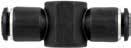
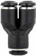
55500-6-M66M6

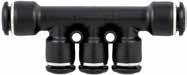
6.13 55 Serie s 55330 4 POSITION Y D1 F D2 L H F C 55350 REDUCTION MANIFOLD
BANJO BODY
BANJO BODY Part No. D1D2 CLFH 55330-4-4 5/32 (4)5/32 (4) .425(10,8)1.319(33,5).130(3,3).846(21,5) 55330-4-6 5/32 (4) 6 .425(10,8)1.358(34,5).130(3,3).846(21,5) 55330-6-666 .524(13,3)1.555(39,5).130(3,3)1.055(26,8) 55330-6-86 5/16 (8) .524(13,3)1.575(40).130(3,3)1.055(26,8)
No. Tube ABL1L2CED1D2 55350-6-4 6 - 5/32(4) .531(13,5).236(6)2.913(74).858(21,8).531(13,5).130(3,3).551(14).472(12) 55350-8-4 5/16(8)
5/32(4)
55500 SINGLE
55510 DOUBLE
Part
-
10
5/16(8)
A L2 E C B A D2 D1 L1 Part No. TubeA BLCHD 55500-4-M5 5/32 (4) M5 .551(14).768(19,5).354(9).394(10) 55500-4-M6 5/32 (4) M6 .551(14).768(19,5).354(9).394(10) 55500-4-1/8 5/32 (4) 1/8 .65(16,5).846(21,5).551(14).394(10) 55500-4-1/4 5/32 (4) 1/4 .728(18,5).925(23,5).708(18).472(12)
55350-10-8
-
55500-5-M55M5 .551(14).807(20,5).354(9).472(12) 55500-5-M65M6 .551(14).807(20,5).354(9).472(12)
.551(14).827(21).354(9).472(12)
.728(18,5)1.004(25,5).709(18).472(12) 55500-8-1/8 5/16 (8) 1/8 .650(16,5).925(23,5).551(14).551(14) 55500-8-1/4 5/16 (8) 1/4 .728(18,5)1.024(26).709(18).551(14) 55500-8-3/8 5/16 (8) 3/8 .866(22)1.083(27,5).827(21).551(14) 55500-10-1/4101/4 .728(18,5)1.220(31).708(18).669(17) 55500-10-3/8103/8 .866(22)1.201(30,5).827(21).669(17) 55500-12-3/8123/8 .866(22)1.280(32,5).827(21).787(20) 55500-12-1/2121/2 1.024(26)1.378(35)1.024(26).787(20) ForBANJOSTEMassembliessee10.7/10.8/10.9 A B D L CH Part No. TubeA BLCHD 55510-4-M5 5/32 (4) M5 .551(14)1.535(39).354(9).394(10) 55510-4-1/8 5/32 (4) 1/8 .650(16,5)1.693(43).551(14).394(10) 55510-5-1/851/8 .650(16,5)1.772(45).551(14).472(12) 55510-5-1/451/4 .728(18,5)1.969(50).709(18).472(12) 55510-6-1/861/8 .650(16,5)1.811(46).551(14).472(12) 55510-6-1/461/4 .728(18,5)2.008(51).709(18).472(12) 55510-8-1/8 5/16 (8) 1/8 .650(16,5)1.850(47).551(14).551(14) 55510-8-1/4 5/16 (8) 1/4 .728(18,5)2.047(52).709(18).551(14) ForBANJOSTEMassembliessee10.7/10.8/10.9 A B D L CH Page 87
.551(14).827(21).354(9).472(12) 55500-6-1/861/8 .650(16,5).906(23).551(14).472(12) 55500-6-1/461/4
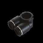

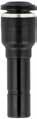
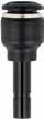
6.14 55 Serie s 55520 DOUBLE BANJO BODY 55620 TERMINAL PLUG 55625 DOUBLE JOINT 55700 TUBE REDUCER 55705 TUBE EXPANDER Part No. TubeA BCLD 55520-4-1/8 5/32 (4) 1/8 .650(16,5).512(13).827(21).472(12) 55520-4-1/4 5/32 (4) 1/4 .728(18,5).610(15,5).945(24).551(14) 55520-6-1/861/8 .650(16,5).512(13).846(21,5).472(12) 55520-6-1/461/4 .728(18,5).610(15,5).965(24,5).551(14) 55520-6-3/863/8 .866(22).531(13,5).984(25).472(12) 55520-8-1/4 5/16 (8) 1/4 .728(18,5).610(15,5).965(24,5).551(14) 55520-8-3/8 5/16 (8) 3/8 .866(22).748(19)1.102(28).669(17) 55520-10-3/8103/8 .866(22).748(19)1.102(28).669(17) ForBANJOSTEMassembliessee10.7/10.8/10.9 B L D A C Part No. Tube DL 55620-4 5/32 (4) .393(10).708(18) 55620-66 .492(12,5).787(20) 55620-8 5/16 (8) .551(14).846(21,5) 55620-1010 .669(17).984(25) 55620-1212 .787(20)1.082(27,5) D L Part No. Tube LL1 55625-4 5/32 (4) 1.358(34,5).630(16) 55625-6 6 1.555(39,5).728(18,5) 55625-8 5/16 (8) 1.654(42).768(19,5) 55625-1010 2.028(51,5).945(24) 55625-1212 2.362(60)1.102(28) 55625-1414 2.736(69,5)1.299(33) L L1 L1 Part No. AB LD 55700-6-46 5/32 (4) 1.339(34).394(10) 55700-8-4 5/16 (8)5/32 (4) 1.496(38).472(12) 55700-8-6 5/16 (8) 6 1.535(39).492(12,5) 55700-10-6106 1.673(42,5).492(12,5) 55700-10-810 5/16 (8) 1.654(42).551(14) 55700-12-6126 1.516(38,5).492(12,5) 55700-12-812 5/16 (8) 1.634(41,5).551(14) 55700-12-101210 1.909(48,5).669(17) 55700-14-814 5/16 (8) 1.476(37,5).551(14) 55700-14-101410 1.969(50).787(20) 55700-14-121412 1.969(50).787(20) D A L B Part No. AB LD 55705-4-6 5/32 (4) 6 1.417(36).472(12) 55705-6-86 5/16 (8) 1.516(38,5).551(14) 55705-8-10810 1.693(43).669(17) 55705-10-121012 1.89(48).787(20) D A L B Page 88
50980 SECURITY CLIPS
50610 POLYAMIDE PLUG

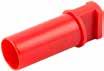
50615
COLORED RELEASE BOTTON COVERS
50991
TOOL FOR DISASSEMBLING
50006
THREAD PACKING FOR THE SWIFTFIT TAPER THREADS
6.15 55 Serie s
Part No. Tube 50980-53 5/32 (4) 50980-5 3/16 (5) 50980-04 1/4 (6) 50980-05 5/16 (8) 50980-06 3/8 (10) 50980-08 1/2 (12) 50980-14 (14) Part No. 0D1 GLL1 50610-33 .197(5)1.201(30,5).709(18) 50610-4 5/32 (4) .236(6)1.162(29,5).611(15,5) 50610-55 .276(7)1.319(33,5).709(18) 50610-66 .315(8)1.260(32).611(15,5) 50610-8 5/16 (8) .394(10)1.398(35,5).768(19.5) 50610-1010 .472(12)1.575(40).768(19.5) 50610-1212 .551(14)1.634(41.5).787(20) 50610-1414 .630(16)1.654(42).768(19.5) Ø D1 L G L1 Part No Color Tube 50615-4BNBLGIROVE 4 50615-6BNBLGIROVE 6 50615-8BNBLGIROVE 8 50615-10BNBLGIROVE 10 50615-12BNBLGIROVE 12 50615-14BNBLGIROVE 14 Part No. 50991 468 1012 Part No. Thread 50006-02 1/8 50006-04 1/4 50006-06 3/8 50006-08 1/2 Page 89
56 SERIES - MINI
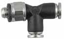
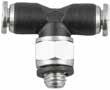


6.16 56 Serie s - Mini
56010 STRAIGHT MALE WITH INTERNAL HEX 56020 STRAIGHT MALE 56115 SWIVEL ELBOW 56215 SWIVEL BRANCH TEE 56225 SWIVEL RUN TEE
Part No. TubeA BHCHD 56010-4-M3 5/32 (4) M3 .118(3).591(15).059(1,5).315(8) 56010-4-M5 5/32 (4) M5 .142(3,6).551(14).098(2,5).335(8,5) 56010-4-M7 5/32 (4) M7 .197(5).551(14).118(3).394(10) 56010-6-M56M5 .142(3,6).630(16).098(2,5).394(10) 56010-6-M76M7 .197(5).630(16).157(4).394(10) BSPP D CH A H B Part No. TubeA BHCH1CH2 56020-2-M32M3 .118(3).433(11).236(6).059(1,5) 56020-2-M52M5 .157(4).354(9).276(7).059(1,5) 56020-3-M33M3 .118(3).433(11).236(6).059(1,5) 56020-3-M53M5 .157(4).394(10).276(7).079(2) 56020-4-M3 5/32 (4) M3 .118(3).571(14,5).315(8)56020-4-M5 5/32 (4) M5 .142(3,6).551(14).354(9).098(2,5) 56020-4-M7 5/32 (4) M7 .197(5).551(14).394(10).118(3) 56020-4-1/8 5/32 (4) 1/8 .197(5).453(11,5).512(13).118(3) 56020-6-M56M5 .142(3,6).630(16).433(11).098(2,5) 56020-6-M76M7 .197(5).630(16).394(10).118(3) 56020-6-1/861/8 .197(5).531(13,5).512(13).157(4) 56020-6-1/461/4 .280(7,1).472(12).630(16).157(4) BSPP H A B CH2 CH1 Part No. TubeA BHLDCH 56115-2-M32M3 .118(3).512(13).433(11).256(6,5).315(8) 56115-2-M52M5 .157(4).492(12,5).433(11).256(6,5).315(8) 56115-3-M33M3 .118(3).512(13).433(11).256(6,5).315(8) 56115-3-M53M5 .157(4).492(12,5).433(11).256(6,5).315(8) 56115-4-M3 5/32 (4) M3 .118(3).394(10).551(14).335(8,5).315(8) 56115-4-M5 5/32 (4) M5 .142(3,6).531(13,5).551(14).335(8,5).315(8) 56115-4-1/8 5/32 (4) 1/8 .197(5).512(13).551(14).335(8,5).512(13) 56115-4-1/4 5/32 (4) 1/4 .280(7,1).512(13).551(14).335(8,5).630(16) 56115-6-M56M5 .142(3,6).610(15,5).630(16).413(10,5).315(8) 56115-6-M76M7 .197(5).623(16).623(16).413(10,5).354(9) 56115-6-1/861/8 .197(5).591(15).630(16).413(10,5).512(13) 56115-6-1/461/4 .280(7,1).591(15).630(16).413(10,5).630(16) BSPP B A H L D CH Part No. TubeA BHLCHD 56215-2-M32M3 .118(3).512(13).866(22).315(8).256(6,5) 56215-2-M52M5 .157(4).492(12,5).866(22).315(8).256(6,5) 56215-3-M33M3 .118(3).512(13).866(22).315(8).256(6,5) 56215-3-M53M5 .157(4).492(12,5).866(22).315(8).256(6,5) BSPP D L B H A CH Part No. TubeA BHLCHD 56225-2-M32M3 .118(3).827(21).433(11).315(8).256(6,5) 56225-2-M52M5 .157(4).827(21).433(11).315(8).256(6,5) 56225-3-M33M3 .118(3).827(21).433(11).315(8).256(6,5) 56225-3-M53M5 .157(4).827(21).433(11).315(8).256(6,5) BSPP H L A D B CH Page 90

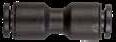

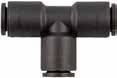
6.17 56 Serie s - Mini 56550 SWIVEL SINGLE BANJO BODY 56040 UNION 56050 BULKHEAD UNION 56130 UNION ELBOW 56230 UNION TEE Part No. TubeA BHLECHD 56550-3-M33M3 .118(3).413(10,5).610(15,5).236(6).079(2).276(7) 56550-3-M53M5 .157(4).413(10,5).610(15,5).236(6).079(2).276(7) BSPP A B H L E D CH Part No. AB CLD 56040-4-4 5/32 (4)5/32 (4) .335(8,5).984(25).335(8,5) 56040-6-666 .413(10,5)1.102(28).413(10,5) 56040-8-6 5/16 (8) 6 .413(10,5)1.358(34,5).551(14) L D C A B Part No. Tube MLCHAmax 56050-4 5/32 (4) M10x1.984(25).512(13).217(5,5) 56050-66 M12x11.102(28).591(15).335(8,5) A max L M CH Part No. Tube LD 56130-22 .571(14,5).256(6,5) 56130-33 .571(14,5).256(6,5) 56130-4 5/32 (4) .748(19).335(8,5) 56130-66 .886(22,5).413(10,5) L D Part No. Tube HLD 56230-22 .571(14,5).866(22).256(6,5) 56230-33 .571(14,5).866(22).256(6,5) 56230-4 5/32 (4) .748(19)1.142(29).335(8,5) 56230-66 .886(22,5)1.358(34,5).413(10,5) D H L Page 91
6.18 55 Serie s NOTES Page 92
MIST FIT Series
reserves the right to vary models and dimensions without notice


Aignep
84000H Pag.7.6 84040H Pag.7.7 84041H 84042H Pag.7.7 84111H Pag.7.6 84130H Pag.7.7 84131H Pag.7.8 84202H Pag.7.8 84211H Pag.7.6 84230H Pag.7.8 84320H Pag.7.9 84610H Pag.7.9 84620H Pag.7.9 84700H Pag.7.10 84707H Pag.7.10 84708H Pag.7.10 Page 93
PUSH - IN FITTINGS FOR MISTINGS SYSTEMS
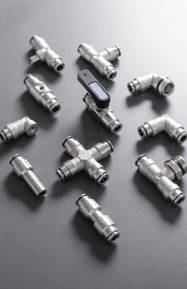
MIST FIT Series
MIST FIT Page 94
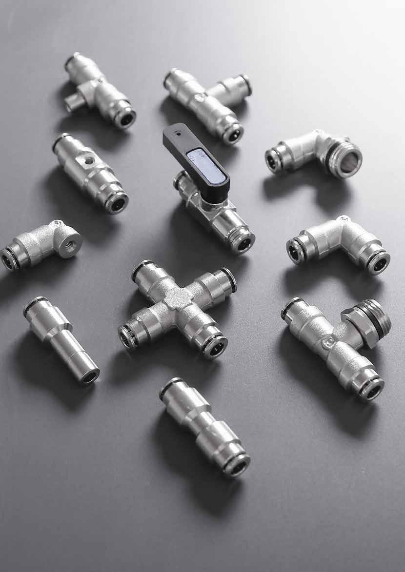


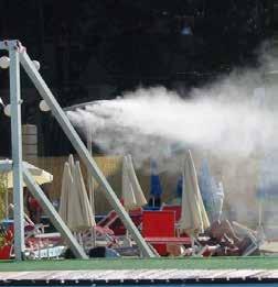


EXAMPLE Page 95
APPLICATION
TECHNICAL CHARACTERISTICS
Reference Standard Pressure Rating
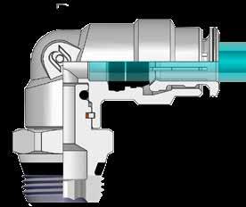
Bar Media
0 bar ~ 85 bar 0 MPa ~ 8.5 MPa
• Water
Tubing Compatibility
PLASTIC TUBES:
PA12, Metalic tubes.
* Copper or Steel tube, most be grooved.
Component Parts and Materials
1 Nickel-plated brass Body
2 Nickel-plated brass Clamping washer
3 NBR O-Ring
4 Nbr Thread packing
5 Seeger
Applications
- Centralized nebulization
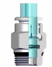
- Dust destruction
- Temperatures destruction
- Humidification
- Greenhouses irrigation
- Aromas diffusion
- insects disinfestation
Advantages
1 Immediate connection and disconnection, absolute endurance
2 Two available threads
3 Protective chemical nickel plating
4 Strength because of the entire realization in metal
5 Large range in order to satisfy the most demanding applications
7.4 MIST FIT Series 1907/2006 2011/65/CE SILICON FREE PED 2014/68/UE
NBR 0º F ~ 176º F 0º C ~ 80º C Temperatures Rating 2 1 4 3 5 Page 96
THREADS & ADVANTAGES
Our SWIFTFIT universal fittings also work on non-flat surfaces without compromising an air-tight seal.
The SWIFTFIT Universal Thread has been designed to offer the following advantages to the end users:
• Reduced overall length
• Smaller hex dimensions compared to parallel threads
• Fits with various parallel and tapered threads All SWIFTFIT fittings have been equipped with threads and an NBR thread seal that will universally connect to all thread types.
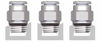
7.5 MIST FIT Series
Torque Specifications Recommended Torque Thread Size Min. Max. 1/8 5 Nm 7 Nm 1/4 5 Nm 7 Nm 3/8 5 Nm 7 Nm 1/2 5 Nm 7 Nm NPT NPTF Tapered ISO 228 BSP PF Parallell ISO 7 BSPT PT Tapered ISO 7 BSPP Parallell One fitting... Endless possibilities Inclined Concave Convex Page 97

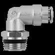
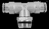
7.6 MIST FIT Series
STRAIGHT MALE 84111H SWIVEL ELBOW
SWIVEL BRANCH TEE Part No. TubeA BLCH1CH2 84000H-1/4-1/41/41/4 .276(7)1003(25.5).551(14)84000H-1/4-3/81/43/8 .295(7,5)1023(26).669(17)84000H-3/8-1/43/81/4 .276(7)1181(30).709(18).276(7) 84000H-3/8-3/83/83/8 .295(7,5)1063(27).709(18).315(8) B L A CH1 CH2 Part No. TubeA BL1L2CH1CH2 84111H-1/4-1/41/41/4 .276(7)1.063(27).926(23,5).433(11).591(15) 84111H-1/4-3/81/43/8 .295(7,5)1.063(27).945(24).433(11).669(17) 84111H-3/8-1/43/81/4 .276(7)1.103(28)1.083(27,5).551(14).630(16) 84111H-3/8-3/83/83/8 .295(7,5)1.103(28)1.083(27,5).551(14).669(17) L1 L2 A B CH1 CH2 Part No. TubeA BL1L2CH1CH2 84211H-1/4-1/41/41/4 .276(7)2049(52)1003(25.5).433(11).591(15) 84211H-1/4-3/81/43/8 .295(7,5)2049(52).946(24).433(11).669(17) 84211H-3/8-1/43/81/4 .276(7)2.244(57)1.163(29,5).630(16).630(16) 84211H-3/8-3/83/83/8 .295(7,5)2.244(57)1.083(27,5).630(16).669(17) L1 L2 B A CH1 CH2 Page 98
84000H
84211H
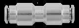
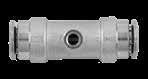
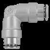
7.7 MIST FIT Series 84040H UNION 84041H
UNION FOR NOZZLE ADAPTER 84130H UNION ELBOW Part No. TubeA L 84040H-1/41/41/8 1.712(43.5) 84040H-1/43/81/8 1.850(47) L Part No. TubeC L 84041H-1/41/4 10-24 UNC 1.929(49) 84041H-3/83/8 10-24 UNC 2049(52) 84042H-3/83/8 12-24 UNC 2049(52) UNC L C Part No. Tube LCH 84130H-1/41/4 1.023(26).433(11) 84130H-3/83/8 1.103(28).551(14) UNC L L CH Page 99
- 84042H
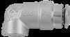
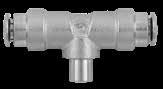
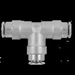
7.8 MIST FIT Series 84131H ELBOW FOR NOZZLE ADAPTER 84202H TEE PLUG IN 84230H UNION TEE Part No. TubeC L1L2CH 84131H-1/41/4 10-24 UNC .984(25).394(10).433(11) 84131H-3/83/8 10-24 UNC 1.103(28).453(11,5).551(14) UNC L2 L1 C CH1 Part No. TubeC L1L2CH 84202H-1/41/4 10-24 UNC 2049(52).689(17,5).433(11) UNC L1 L2 C CH Part No. Tube L1L2CHCH2 84230H-1/41/4 2.049(52)1.023(26).433(11).591(15) 84230H-3/83/8 2.244(57)1.103(28).630(16).669(17) L1 L2 CH Page 100
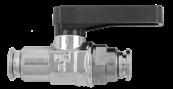
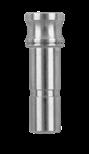
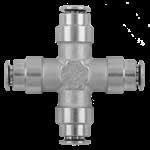
7.9 MIST FIT Series 84320H BALL VALVE - TUBE
TUBE 84610H PLUG 84620H UNION CROSS Part No. Tube LHGES 84320H-1/41/4 2.303(58.5).878(22.5)1.378(35).709(18)-.748(19) 84320H-3/83/8 2.461(62.5).878(22.5)1.378(35).709(18)-.748(19) G H L ES Part No. Tube LH 84610H-1/41/4 1.201(30,5).925(23,5) 84610-3/83/8 1.181(30).867(22) A L H Part No. Tube LCH 84620H-1/41/4 2.049(52).512(13) 84620H-3/83/8 2.244(57).669(17) L L CH Page 101
X
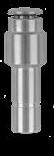

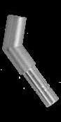
7.10 MIST FIT Series 84700H REDUCER 84707H REDUCER FOR NOZZLE ADAPTER 84708H 45˚ REDUCER FOR NOZZLE ADAPTER Part No. TubeA LH 84700H-1/4-3/81/43/8 1.634(41.5).866(22) 84700H-3/8-1/43/81/4 1.909(48.5).925(23,5) A L H Part No. AB LHCH 84707H-1/41/4 10-24 UNC 1.240(31,5).925(23,5).315(8) UNC H L A B CH Part No. AB LH 84708H-1/41/4 10-24 UNC 1.870(47,5).925(23,5) UNC L H A B Page 102
60 Series - Metric Swiftfit Stainless Fittings Inch Tube
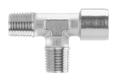
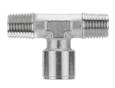


62 Series
Aignep reserves the right to vary models and dimensions without notice
60000 Pg.8.5 60110 Pg.8.5 60210 Pg.8.6 60000 Pg.8.5 60110 Pg.8.5 60210 Pg.8.6 60040 Pg.8.7 60050 Pg.8.7
Metric Tube 60230 Pg.8.8 60230 Pg.8.13 62340 Pg.8.16 62360 Pg.8.16 60005 Pg.8.10 62000 Pg.8.14 60600 Pg.8.13 62400 Pg.8.16 60110 Pg.8.10 62020 Pg.8.14 62440 Pg.8.17 60210 Pg.8.11 62040 Pg.8.14 62450 Pg.8.17 60020 Pg.8.9 62080 Pg.8.14 62520 Pg.8.18 60115 Pg.8.9 62300 Pg.8.15 62510 Pg.8.18 60215 Pg.8.10 62310 Pg.8.15 60050 Pg.8.12 62320 Pg.8.15 62540 Pg.8.18 60040 Pg.8.11 62315 Pg.8.15 60130 Pg.8.7 60130 Pg.8.12 62325 Pg.8.15 60230X Pg.8.8 60310X Pg.8.8 60130X Pg.8.8 60211X Pg.8.7 60111X Pg.8.6 60211X Pg.8.7 60111X Pg.8.6 60230X Pg.8.13 60310X Pg.8.13 60130X Pg.8.12 60211X Pg.8.11 60111X Pg.8.11 60215X Pg.8.10 60115X Pg.8.9 62500 Pg.8.17 62355 Pg.8.16 62610 Pg.8.18 62600 Pg.8.18 62420 Pg.8.17 62430 Pg.8.17 Page 103
STAINLESS STEEL PUSH-TO-CONNECT FITTINGS AND ADAPTERS

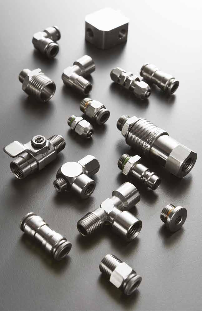
60-62 Series
60000 62000 Page 104
Reference
TECHNICAL CHARACTERISTICS
Bar
Pressure Rating
Vacuum ~ 290 PSI -0.99 bar ~ 20 bar -0.099 MPa ~ 2.0 MPa
Media
• Compressed Air
• Vacuum Water Steam
Advantages
1 The 316L Stainless Steel gripper ensures a tight clamp for tubes of any material without damaging the tube’s surface. The secure connection between the tube and the fitting will hold up to severe conditions such as impact and vibrations.
2 The shape of the safety ring and the molded seal perfectly seal off the tube, creating a vacuum.
3 Series with several types of threads: SWIFTFIT UNF BSPP BSPT
4 All straight fittings can be tightened with an Allen wrench because of our internal hex design. This enables the end user to tighten the fitting in spaces too small for an openend wrench.
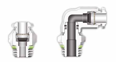
5 Our rotating Swivel Elbow fittings are equipped with a safety ring that enables the fitting to rotate without losing a tight seal.
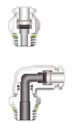
Component Parts and Materials
1 Stainless Steel Release Collet
2 Stainless Steel Body
3 FKM Thread Seal
4 Stainless Steel Sleeve
5 Stainless Steel Gripper
6 Technopolymer Safety Ring
7 FKM Molded Seal
8 Stainless Steel Thread Body
9 FKM Seal
10 Safety Ring
Tubing Compatibility
Nylon 6 - 11 -12
Polyethylene
Polyurethane (“98 Shore A for best result)
PTFE FEP
8.3 60-62 Series
Standard 1907/2006 2011/65/CE PED 2014/68/UE ISO 14743:2004 SILICON FREE
FKM 5º F ~ 392º F -15º C ~ 200º C Temperatures Rating Applications Pneumatic Automation
Automotive
Textile, Packaging Compressed Air Circuit • Vacuum 1 2 3 4 5 6 7 9 10 8 1 3 4 5 2 NSF/ANSI 169 Page 105
•
•
THREADS & ADVANTAGES
One fitting... Endless possibilities
The SWIFTFIT Universal Thread has been designed to offer the following advantages to the end users:
• Reduced overall length
• Smaller hex dimensions compared to parallel threads
• Fits with various parallel and tapered threads
• All SWIFTFIT fittings have been equipped with threads and an NBR thread seal that will universally connect to all thread types.
Our SWIFTFIT universal fittings also work on non-flat surfaces without compromising an air-tight seal.
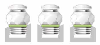
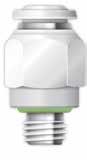
UNF Threads
The UNF Thread has been designed to offer the following advantages to the end users:
• Standard USA design
Designed for use in UNF connections with an integrated NBR o-ring that provides a perfect seal
BSPP Threads
The BSPP Thread has been designed to offer the following advantages to the end users:
• Standard ISO 228 and ISO R/262
• Designed for use in BSPP connections with an integrated NBR o-ring that provides a perfect seal
• Completely reusable Torque
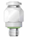
8.4 60-62 Series NPT NPTF Tapered ISO 228 BSP PF Parallell ISO 7 BSPT PT Tapered ISO 7 BSPP Parallell
Specifications Recommended Torque Thread Size Min. Breaking torque M5 0.8 Nm 3.2 Nm 1/2 3 Nm 8 Nm 1/4 9 Nm 30 Nm 3/8 10 Nm 60 Nm 1/2 12 Nm 50 Nm Torque Specifications Recommended Torque Thread Size Min. Max. 1/8 5 Nm 7 Nm 1/4 5 Nm 7 Nm 3/8 5 Nm 7 Nm 1/2 5 Nm 7 Nm
Specifications Recommended Torque Thread Size Min. Breaking Torque 10/32 0.8 Nm 3.2 Nm Inclined Concave Convex Page 106
Torque
60000


STRAIGHT MALE
* For part numbers with 10-32 threads
60110
* For part numbers with 10-32 threads


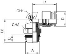


8.5 60-62 Series
SWIVEL ELBOW
Part No. TubeA BLCH1CH2C *60000-53-32 5/32 (4) 10/32 .157(4).826(21).393(10).078(2).314(8) 60000-53-02 5/32 (4) 1/8 .216(5,5).708(17,5).433(11).118(3)60000-53-04 5/32 (4) 1/4 .275(7).767(19,5).551(14).118(3)*60000-04-321/410/32 .157(4).906(23).472(12).078(2).472(12) 60000-04-021/41/8 .334(8,5).925(23,5).511(13).157(4)60000-04-041/41/4 .275(7).807(20,5).551(14).157(4)60000-05-02 5/16 (8) 1/8 .216(5,5).944(24).551(14).196(5)60000-05-04 5/16 (8) 1/4 .275(7).846(21,5).551(14).236(6)60000-06-043/81/4 .275(7)1.279(32,5).669(17).275(7)60000-06-063/83/8 .295(7,5)1.161(29,5).708(18).275(7)60000-06-083/81/2
60000-08-061/23/8
60000-08-081/21/2
CH2 L A B CH1 UNF CH1 L B C A CH2 Part No. TubeA BL1L2CH1CH2D *60110-53-32 5/32 (4) 10/32 .157(4).708(18).629(16).354(9).314(8).394(10) 60110-53-02 5/32 (4) 1/8 .216(5,5).708(18).688(17,5).354(9).511(13).394(10) 60110-53-04 5/32 (4) 1/4 .275(7).708(18).688(17,5).354(9).551(14).394(10) 60110-04-021/41/8 .216(5,5).826(21).748(19).433(11).511(13).492(12,5) 60110-04-041/41/4 .275(7).826(21).748(19).433(11).590(15).492(12,5) 60110-05-02 5/16 (8) 1/8 .216(5,5).885(22,5).826(21).472(12).511(13).571(14,5) 60110-05-04 5/16 (8) 1/4 .275(7).885(22,5).826(21).472(12).590(15).571(14,5) 60110-06-043/81/4 .275(7)1.023(26).984(25).629(16).629(16).689(17,5) 60110-06-063/83/8 .295(7,5)1.023(26).925(23,5).629(16).669(17).689(17,5) 60110-06-083/81/2 .354(9)1.023(26)1.023(26).629(16).826(21).689(17,5) 60110-08-061/23/8 .295(7,5)1.200(30,5)1.003(25,5).748(19).787(20).807(20,5) 60110-08-081/21/2 .354(9)1.200(30,5)1.102(28).748(19).826(21).807(20,5)
UNF L2 B A CH2 CH1 L1 C Page 107
.354(9)1.003(25,5).669(17).314(8)-
.295(7,5)1.220(31).826(21).354(9)-
.354(9)1.220(31).826(21).393(10)-
UNTIL THE END STOCK
60111X
SWIVEL ELBOW
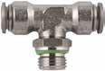
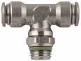
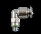
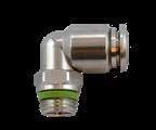
* For part numbers with 10-32 threads
60210
SWIVEL BRANCH TEE
* For part numbers with 10-32 threads
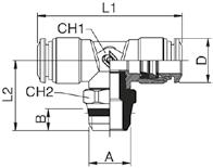
8.6 60-62 Series
Part No. TubeA BCL1L2CH *60111X-53-32 5/32 (4) 10/32 0,157(4)0,394(10)0,61(15,5)0,63(16)0,315(8) 60111X-53-02 5/32 (4) 1/8 0,217(5,5)0,394(10)0,61(15,5)0,61(15,5)0,433(11) 60111X-53-04 5/32 (4) 1/4 0,276(7)0,394(10)0,61(15,5)0,689(17,5)0,591(15) 60111X-04-021/41/8 0,217(5,5)0,492(12,5)0,709(18)0,669(17)0,433(11) 60111X-04-041/41/4 0,276(7)0,492(12,5)0,709(18)0,748(19)0,591(15) 60111X-05-02 5/16 (8) 1/8 0,217(5,5)0,571(14,5)0,787(20)0,846(21,5)0,472(12) 60111X-05-04 5/16 (8) 1/4 0,276(7)0,571(14,5)0,787(20)0,846(21,5)0,591(15) 60111X-06-043/81/4 0,276(7)0,669(17)0,925(23,5)1,004(25,5)0,591(15) 60111X-06-063/83/8 0,295(7,5)0,669(17)0,925(23,5)0,925(23,5)0,669(17) 60111X-06-083/81/2 0,354(9)0,669(17)0,925(23,5)1,063(27)0,827(21) 60111X-08-061/23/8 0,295(7,5)0,807(20,5)1,083(27,5)1,024(26)0,669(17) 60111X-08-081/21/2 0,354(9)0,807(20,5)1,083(27,5)1,063(27)0,827(21) A B L2 L1 C CH UNF A B L2 L1 C CH Part No. TubeA BL1L2CH1CH2D *60210-53-32 5/32 (4) 10/32 .157(4)1.417(36).629(16).354(9).314(8).394(10) 60210-53-02 5/32 (4) 1/8 .216(5,5)1.417(36).688(17,5).354(9).511(13).394(10) 60210-53-04 5/32 (4) 1/4 .275(7)1.417(36).688(17,5).354(9).590(15).394(10) 60210-04-021/41/8 .216(5,5)1.653(42).748(19).433(11).511(13).492(12,5) 60210-04-041/41/4 .275(7)1.653(42).748(19).433(11).590(15).492(12,5) 60210-05-02 5/16 (8) 1/8 .216(5,5)1.771(45).826(21).472(12).511(13).571(14,5) 60210-05-04 5/16 (8) 1/4 .275(7)1.771(45).826(21).472(12).590(15).571(14,5) 60210-06-043/81/4 .275(7)2.047(52).984(25).629(16).629(16).689(17,5) 60210-06-063/83/8 .295(7,5)2.047(52).925(23,5).629(16).669(17).689(17,5) 60210-06-083/81/2 .354(9)2.047(52)1.023(26).629(16).826(21).689(17,5) 60210-08-061/23/8 .295(7,5)2.381(60,5)1.003(25,5).748(19).787(20).807(20,5) 60210-08-081/21/2 .354(9)2.381(60,5)1.102(28).748(19).826(21).807(20,5) UNTIL THE END STOCK UNF CH1 B L2 CH2 A L1 C Page 108
60211X
SWIVEL BRANCH TEE
* For part numbers with 10-32 threads 60040


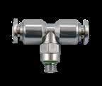
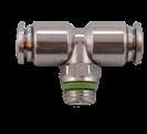
8.7 60-62 Series
UNION
BULKHEAD UNION
UNION ELBOW Part No. TubeA BCL1L2CH *60211X-53-32 5/32 (4) 10/32 0,157(4)0,394(10)1,201(30,5)0,63(16)0,315(8) 60211X-53-02 5/32 (4) 1/8 0,217(5,5)0,394(10)1,201(30,5)0,61(15,5)0,433(11) 60211X-53-04 5/32 (4) 1/4 0,276(7)0,394(10)1,201(30,5)0,689(17,5)0,591(15) 60211X-04-021/41/8 0,217(5,5)0,492(12,5)1,417(36)0,669(17)0,433(11) 60211X-04-041/41/4 0,276(7)0,492(12,5)1,417(36)0,748(19)0,591(15) 60211X-05-02 5/16 (8) 1/8 0,217(5,5)0,571(14,5)1,575(40)0,846(21,5)0,472(12) 60211X-05-04 5/16 (8) 1/4 0,276(7)0,571(14,5)1,575(40)0,846(21,5)0,591(15) 60211X-06-043/81/4 0,276(7)0,669(17)1,85(47)1,004(25,5)0,591(15) 60211X-06-063/83/8 0,295(7,5)0,669(17)1,85(47)0,925(23,5)0,669(17) 60211X-06-083/81/2 0,354(9)0,669(17)1,85(47)1,063(27)0,827(21) 60211X-08-061/23/8 0,295(7,5)0,807(20,5)2,165(55)1,024(26)0,669(17) 60211X-08-081/21/2 0,354(9)0,807(20,5)2,165(55)1,063(27)0,827(21) A L2 L1 C B CH UNF C A B L2 L1 CH Part No. Tube LB 60040-53 5/32 (4) 1.220(31).393(10) 60040-041/4 1.377(35).492(12,5) 60040-05 5/16 (8) 1.437(36,5).570(14,5) 60040-063/8 1.653(42).688(17,5) 60040-081/2 1.889(48).807(20,5) B L Part No. TubeM LCHAmax 60050-53 5/32 (4) M12x1 1.220(31).669(17).275(7) 60050-041/4M14x1 1.377(35).669(17).354(9) 60050-05 5/16 (8) M16x1 1.456(37).748(19).413(10,5) 60050-063/8M20x1 1.653(42)1.023(26).492(12,5) 60050-081/2M22x1 1.889(48)1.023(26).649(16,5) L M A max CH Part No. Tube LCHC 60130-53 5/32 (4) .708(18).354(9).394(10) 60130-041/4 .826(21).433(11).492(12,5) 60130-05 5/16 (8) .885(22.5).472(12).571(14,5) 60130-063/8 1.023(26).629(16).688(17,5) 60130-081/2 1.200(30,5).748(19).807(20,5) UNTIL THE END STOCK CH L L C Page 109
60050
60130
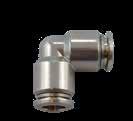
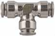
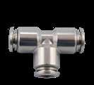
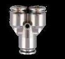
8.8 60-62 Series 60130X UNION ELBOW 60230 UNION TEE 60230X UNION TEE 60310X UNION TEE Part No. Tube CL 60130X-53 5/32 (4) 0,394(10)0,63(16) 60130X-041/4 0,492(12,5)0,768(19,5) 60130X-05 5/16 (8) 0,571(14,5)0,827(21) 60130X-063/8 0,669(17)0,098(2,5) 60130X-081/2 0,807(20,5)1,142(29) C L L Part No. Tube L1L2CHC 60230-53 5/32 (4) 1.417(36).708(18).354(9).394(10) 60230-041/4 1.653(42).826(21).433(11).492(12,5) 60230-05 5/16 (8) 1.771(45).885(22.5).472(12).571(14,5) 60230-063/8 2.047(52)1.023(26).629(16).689(17,5) 60230-081/2 2.381(60.5)1.200(30.5).748(19).807(20,5) UNTIL THE END STOCK CH L1 L2 C Part No. Tube CL1L2 60230X-53 5/32 (4) 0,394(10)1,26(32)0,63(16) 60230X-041/4 0,492(12,5)1,535(39)0,768(19,5) 60230X-05 5/16 (8) 0,571(14,5)1,654(42)0,827(21) 60230X-063/8 0,669(17)1,929(49)0,965(24,5) 60230X-081/2 0,807(20,5)2,264(57,5)1,142(29) C L1 L2 Part No. Tube LAC 60310X-53 5/32 (4) .433(11).394(10)1.22(31) 60310X-05 5/16 (8) .61(15.5).571(14.5)1.575(40) A C L Page 110
60020-8-1/4
.315(8).591(15).925(23,5).591(15).236(6)
60020-10-1/4101/4 .315(8).630(16)1.181(30).669(17).315(8)
60020-10-3/8103/8 .354(9).787(20)1.063(27).669(17).315(8)
60020-10-1/2101/2 .394(10).669(17)1.181(30).866(22).315(8)
60020-12-3/8123/8 .354(9).827(21)1.339(34).827(21).315(8)
60020-12-1/2121/2 .394(10).984(25)1.22(31).866(22).394(10)
60020-14-1/2141/2 .394(10).984(25)1.26(32).866(22).433(11)
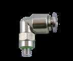
Part No. TubeA BCL1L2CH1CH2
60115-4-M5
60115-4-1/4
.236(6).394(10).709(18).669(17).354(9).512(13)
.157(4).394(10).709(18).591(15).354(9).315(8) 60115-4-1/8
.315(8).394(10).709(18).768(19,5).354(9).591(15)
60115-6-M56M5 .157(4).492(12,5).827(21).709(18).433(11).394(10)
60115-6-1/861/8 .236(6).492(12,5).827(21).748(19).433(11).512(13)
60115-6-1/461/4 .315(8).492(12,5).827(21).846(21,5).433(11).591(15)
60115X-4-1/8
.315(8).394(10).61(15.5).728(18.5).591(15)
.236(6).394(10).61(15.5).63(16).512(13) 60115X-4-1/4
60115X-6-M56M5 .157(4).492(12.5).709(18).689(17.5).315(8)
60115X-6-1/861/8 .236(6).492(12.5).709(18).689(17.5).512(13)
60115X-6-1/461/4 .315(8).492(12.5).709(18).787(20).591(15)
60115X-6-3/863/8 .354(9).492(12.5).709(18).906(23).787(20)
60115X-8-1/8
60115X-12-3/8123/8
60115X-12-1/2121/2
60115X-14-1/2141/2
8.9 60-62 Series 60020 STRAIGHT MALE 60115 SWIVEL ELBOW 60115X SWIVEL ELBOW
Part No. TubeA BCLCH1CH2 60020-4-M5 5/32 (4) M5 .157(4).315(8).787(20).394(10).079(2) 60020-4-1/8 5/32 (4) 1/8 .236(6).512(13).768(19,5).394(10).118(3) 60020-4-1/4 5/32 (4) 1/4 .315(8).591(15).768(19,5).591(15).118(3) 60020-6-M56M5 .157(4).394(10).906(23).472(12).079(2) 60020-6-1/861/8 .236(6).512(13).925(23,5).512(13).157(4) 60020-6-1/461/4 .315(8).591(15).925(23,5).591(15).157(4) 60020-8-1/8 5/16 (8) 1/8 .236(6).512(13)1.004(25,5).551(14).197(5)
316 STAINLESS STEEL PUSH-TO-CONNECT FOR METRIC TUBE
5/16 (8) 1/4
CH1 L B C A CH2
BSPP
5/32 (4) 1/8
5/32 (4) M5
5/32 (4) 1/4
60115-8-1/8 5/16 (8) 1/8
60115-8-1/4 5/16 (8) 1/4 .315(8).571(14,5).886(22,5).846(21,5).472(12).591(15) 60115-10-1/4101/4
60115-12-3/8123/8
60115-12-1/2121/2 .394(10).807(20,5)1.201(30,5)1.240(31,5).748(19).866(22) UNTIL THE END STOCK BSPP L2 B A CH2 CH1 L1 C Part No. TubeA BCL1L2CH 60115X-4-M5 5/32 (4) M5 .157(4).394(10).61(15.5).63(16).315(8)
.236(6).571(14,5).886(22,5).768(19,5).472(12).512(13)
.315(8).689(17,5)1.024(26).906(23).630(16).591(15) 60115-10-3/8103/8 .354(9).689(17,5)1.024(26)1.043(26,5).630(16).827(21) 60115-10-1/2101/2 .394(10).689(17,5)1.024(26)1.142(29).630(16).866(22)
.354(9).807(20,5)1.201(30,5)1.142(29).748(19).827(21)
5/32 (4) 1/8
5/32 (4) 1/4
5/16 (8) 1/8
60115X-8-1/4 5/16 (8) 1/4 .315(8).571(14.5).787(20).827(21).591(15) 60115X-8-3/8 5/16 (8) 3/8 .354(9).571(14.5).787(20).945(24).787(20) 60115X-10-1/4101/4 .315(8).669(17).925(23.5)1.083(27.5).591(15)
.354(9).669(17).925(23.5).984(25).787(20)
.394(10).669(17).925(23.5)1.043(26.5).984(25)
.236(6).571(14.5).787(20).906(23).512(13)
60115X-10-3/8103/8
60115X-10-1/2101/2
.354(9).807(20.5)1.083(27.5)1.201(3.5).787(20)
.394(10).807(20.5)1.083(27.5)1.122(28.5).984(25)
A B L1 C CH Page 111
.394(10).846(21.5)1.083(27.5)1.299(33).984(25) BSPP

8.10 60-62 Series 60215 SWIVEL BRANCH TEE 60215X SWIVEL BRANCH TEE 60005 STRAIGHT MALE 60110 SWIVEL ELBOW Part No. TubeA BCL1L2CH1CH2 60215-4-M5 5/32 (4) M5 .157(4).394(10)1.417(36).591(15).354(9).315(8) 60215-4-1/8 5/32 (4) 1/8 .236(6).394(10)1.417(36).709(18).354(9).512(13) 60215-4-1/4 5/32 (4) 1/4 .315(8).394(10)1.417(36).807(20,5).354(9).591(15) 60215-6-1/861/8 .236(6).492(12,5)1.654(42).748(19).433(11).512(13) 60215-6-1/461/4 .315(8).492(12,5)1.654(42).846(21,5).433(11).591(15) 60215-8-1/8 5/16 (8) 1/8 .236(6).571(14,5)1.772(45).787(20).472(12).512(13) 60215-8-1/4 5/16 (8) 1/4 .315(8).571(14,5)1.772(45).866(22).472(12).591(15) 60215-10-1/4101/4 .315(8).689(17,5)2.047(52).925(23,5).630(16).591(15) 60215-10-3/8103/8 .354(9).689(17,5)2.047(52)1.063(27).630(16).827(21) 60215-10-1/2101/2 .394(10).689(17,5)2.047(52)1.161(29,5).630(16).866(22) 60215-12-3/8123/8 .354(9).807(20,5)2.402(61)1.142(29).748(19).827(21) 60215-12-1/2121/2 .394(10).807(20,5)2.402(61)1.240(31,5).748(19).866(22) UNTIL THE END STOCK BSPP CH1 B L2 CH2 A L1 C BSPP Part No. TubeA BCL1L2CH 60215X-4-M5 5/32 (4) M5 .157(4).394(10)1.201(30.5).63(16).315(8) 60215X-4-1/8 5/32 (4) 1/8 .236(6).394(10)1.201(30.5).63(16).512(13) 60215X-4-1/4 5/32 (4) 1/4 .315(8).394(10)1.201(30.5).728(18.5).591(15) 60215X-6-M56M5 .157(4).492(12.5)1.417(36).689(17.5).315(8) 60215X-6-1/861/8 .236(6).492(12.5)1.417(36).689(17.5).512(13) 60215X-6-1/461/4 .315(8).492(12.5)1.417(36).787(20).591(15) 60215X-8-1/8 5/16 (8) 1/8 .236(6).571(14.5)1.575(40).906(23).512(13) 60215X-8-1/4 5/16 (8) 1/4 .315(8).571(14.5)1.575(40).827(21).591(15) 60215X-10-1/4101/4 .315(8).669(17)1.85(47)1.083(27.5).591(15) 60215X-10-3/8103/8 .354(9).669(17)1.85(47).984(25).787(20) 60215X-10-1/2101/2 .394(10).669(17)1.85(47)1.043(26.5).984(25) 60215X-12-3/8123/8 .354(9).807(20.5)2.165(55)1.201(30.5).787(20) 60215X-12-1/2121/2 .394(10).807(20.5)2.165(55)1.122(28.5).984(25) 60215X-14-1/2141/2 .394(10).846(21.5)2.185(55.5)1.299(33).984(25) C A B L2 L1 CH Part No. TubeA BLCH1CH2 60000-53-02 5/32 (4) 1/8 .216(5,5).708(17,5).433(11).118(3) 60000-53-04 5/32 (4) 1/4 .275(7).767(19,5).551(14).118(3) 60005-6-1/861/8 .334(8,5).925(23,5).511(13).157(4) 60005-6-1/461/4 .275(7).807(20,5).551(14).157(4) 60000-05-02 5/16 (8) 1/8 .216(5,5).944(24).551(14).196(5) 60000-05-04 5/16 (8) 1/4 .275(7).846(21,5).551(14).236(6) 60005-10-1/4101/4 .275(7)1.279(32,5).669(17).275(7) 60005-10-3/8103/8 .295(7,5)1.161(29,5).708(18).275(7) 60005-10-1/2101/2 .354(9)1.024(26).826(21).815(8) 60005-12-3/8123/8 .295(7,5)1.220(31).826(21).354(9) 60005-12-1/2121/2 .354(9)1.220(31).826(21).393(10) CH2 L A B CH1 Part No. TubeA BCL1L2CH1CH2 60110-4-1/8 5/32 (4) 1/8 .394(10).295(7,5).709(18).689(17,5).354(9).433(11) 60110-4-1/4 5/32 (4) 1/4 .394(10).433(11).709(18).846(21,5).354(9).551(14) 60110-6-1/861/8 .492(12,5).295(7,5).827(21).768(19,5).433(11).433(11) 60110-6-1/461/4 .492(12,5).433(11).827(21).925(23,5).433(11).551(14) 60110-8-1/8 5/16 (8) 1/8 .571(14,5).295(7,5).886(22,5).787(20).472(12).433(11) 60110-8-1/4 5/16 (8) 1/4 .571(14,5).433(11).886(22,5).945(24).472(12).551(14) 60110-10-1/4101/4 .689(17,5).433(11)1.024(26)1.004(25,5).630(16).669(17) 60110-10-3/8103/8 .689(17,5).453(11,5)1.024(26)1.063(27).630(16).669(17) 60110-10-1/2101/2 .689(17,5).551(14)1.024(26)1.201(30,5).630(16).866(22) 60110-12-3/8123/8 .807(20,5).453(11,5)1.201(30,5)1.201(30,5).748(19).709(18) 60110-12-1/2121/2 .807(20,5).551(14)1.201(30,5)1.299(33).748(19).866(22) UNTIL THE END STOCK BSPT B L2 A CH1 L1 CH2 C Page 112
60210-8-1/4 5/16 (8) 1/4 .433(11).571(14,5)1.772(45).965(24,5).472(12).551(14)
60210-10-1/4101/4 .433(11).689(17,5)2.047(52)1.024(26).630(16).551(14)
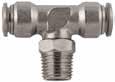
60210-10-3/8103/8 .453(11,5).689(17,5)2.047(52)1.083(27,5).630(16).669(17)
60210-10-1/2101/2 .551(14).689(17,5)2.047(52)1.220(31).630(16).866(22)
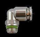
60210-12-3/8123/8 .453(11,5).807(20,5)2.402(61)1.201(30,5).748(19).709(18)
60210-12-1/2121/2
8.11 60-62 Series
ELBOW
BRANCH TEE
BRANCH TEE
UNION Part No. TubeA BCL1L2CH 60111X-53-02 5/32 (4) 1/8 0,217(5,5)0,394(10)0,61(15,5)0,61(15,5)0,433(11) 60111X-53-04 5/32 (4) 1/4 0,276(7)0,394(10)0,61(15,5)0,689(17,5)0,591(15) 60111X-6-1/861/8 0,217(5,5)0,492(12,5)0,709(18)0,669(17)0,433(11) 60111X-6-1/461/4 0,276(7)0,492(12,5)0,709(18)0,748(19)0,591(15) 60111X-05-02 5/16 (8) 1/8 0,217(5,5)0,571(14,5)0,787(20)0,846(21,5)0,472(12) 60111X-05-04 5/16 (8) 1/4 0,276(7)0,571(14,5)0,787(20)0,846(21,5)0,591(15) 60111X-10-1/4101/4 0,276(7)0,669(17)0,925(23,5)1,004(25,5)0,591(15) 60111X-10-3/8103/8 0,295(7,5)0,669(17)0,925(23,5)0,925(23,5)0,669(17) 60111X-10-1/2101/2 0,354(9)0,669(17)0,925(23,5)1,063(27)0,827(21) 60111X-12-3/8123/8 0,295(7,5)0,807(20,5)1,083(27,5)1,024(26)0,669(17) 60111X-12-1/2121/2 0,354(9)0,807(20,5)1,083(27,5)1,063(27)0,827(21) A B L2 L1 C CH Part No. TubeA BCL1L2CH1CH2 60210-4-1/8 5/32 (4) 1/8 .295(7,5).394(10)1.417(36).728(18,5).354(9).433(11) 60210-4-1/4 5/32 (4) 1/4 .433(11).394(10)1.417(36).886(22,5).354(9).551(14) 60210-6-1/861/8 .295(7,5).492(12,5)1.654(42).768(19,5).433(11).433(11) 60210-6-1/461/4 .433(11).492(12,5)1.654(42).925(23,5).433(11).551(14) 60210-8-1/8 5/16 (8) 1/8 .295(7,5).571(14,5)1.772(45).807(20,5).472(12).433(11)
60111X SWIVEL
60210 SWIVEL
60211X SWIVEL
60040
.551(14).807(20,5)2.402(61)1.299(33).748(19).866(22) UNTIL THE
STOCK BSPT L2 B A CH2 CH1 L1 C Part No. TubeA BCL1L2CH 60211X-53-02 5/32 (4) 1/8 0,217(5,5)0,394(10)1,201(30,5)0,61(15,5)0,433(11) 60211X-53-04 5/32 (4) 1/4 0,276(7)0,394(10)1,201(30,5)0,689(17,5)0,591(15) 60211X-6-1/861/8 0,217(5,5)0,492(12,5)1,417(36)0,669(17)0,433(11) 60211X-6-1/461/4 0,276(7)0,492(12,5)1,417(36)0,748(19)0,591(15) 60211X-05-02 5/16 (8) 1/8 0,217(5,5)0,571(14,5)1,575(40)0,846(21,5)0,472(12) 60211X-05-04 5/16 (8) 1/4 0,276(7)0,571(14,5)1,575(40)0,846(21,5)0,591(15) 60211X-10-1/4101/4 0,276(7)0,669(17)1,85(47)1,004(25,5)0,591(15) 60211X-10-3/8103/8 0,295(7,5)0,669(17)1,85(47)0,925(23,5)0,669(17) 60211X-10-1/2101/2 0,354(9)0,669(17)1,85(47)1,063(27)0,827(21) 60211X-12-3/8123/8 0,295(7,5)0,807(20,5)2,165(55)1,024(26)0,669(17) 60211X-12-1/2121/2 0,354(9)0,807(20,5)2,165(55)1,063(27)0,827(21) A L2 L1 C B CH Part No. Tube LB 60040-535/32(4) 1.22(31).413(10.5) 60040-6-536-5/32(4) 1.22(31).492(12.5) 60040-66 1.378(35).492(12.5) 60040-05-65/16(8)-6 1.358(34.5).571(14.5) 60040-055/16(8) 1.437(36.5).571(14.5) 60040-10-0510-5/16(8) 1.496(38).689(17.5) 60040-1010 1.654(42).689(17.5) 60040-12-1012-10 1.732(44).807(20.5) 60040-1212 1.89(48).807(20.5) 60040-1414 1.752(44.5).846(21.5) B L Page 113
END

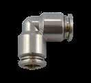
8.12 60-62 Series 60050 BULKHEAD UNION 60130 UNION ELBOW 60130X UNION ELBOW Part No. TubeM LCHAmax 60050-53 5/32 (4) M12x1 1.220(31).669(17).275(7) 60050-66M14x1 1.377(35).669(17).374(9,5) 60050-05 5/16 (8) M16x1 1.456(37).748(19).413(10,5) 60050-1010M20x1 1.653(42)1.023(26).492(12,5) 60050-1212M22x1 1.889(48)1.023(26).649(16,5) L M A max CH Part No. Tube LCHC 60130-53 5/32 (4) .708(18).354(9).394(10) 60130-66 .826(21).433(11).492(12,5) 60130-05 5/16 (8) .885(22.5).472(12).571(14,5) 60130-1010 1.023(26).629(16).688(17,5) 60130-1212 1.200(30,5).748(19).807(20,5) UNTIL THE END STOCK CH L L C Part No. Tube CHC 60130X-53 5/32 (4) .394(10).63(16) 60130X-66 .492(12.5).768(19.5) 60130X-05 5/16 (8) .571(14.5).827(21) 60130X-1010 .669(17).965(24.5) 60130X-1212 .807(20.5)1.142(29) 60130X-1414 .846(21.5)1.122(28.5) C L L Page 114
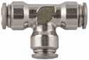
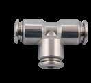
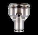

8.13 60-62 Series 60230 UNION TEE 60230X UNION TEE 60310X UNION TEE 60600 STANDPIPE Part No. Tube L1L2CHC 60230-53 5/32 (4) 1.417(36).708(18).354(9).394(10) 60230-66 1.653(42).826(21).433(11).492(12,5) 60230-05 5/16 (8) 1.771(45).885(22.5).472(12).571(14,5) 60230-1010 2.047(52)1.023(26).630(16).689(17,5) 60230-1212 2.381(60.5)1.200(30.5).748(19).807(20,5) UNTIL THE END STOCK CH L1 L2 C Part No. Tube L1L2C 60230X-53 5/32 (4) .394(10)1.26(32).630(16) 60230X-66 .492(12.5)1.535(39).768(19.5) 60230X-05 5/16 (8) .571(14.5)1.654(42).827(21) 60230X-1010 .669(17)1.929(49).965(24.5) 60230X-1212 .807(20,5)2.264(57.5)1.142(29) 60230X-1414 .846(21,5)2.264(57.5)1.122(28.5) C L1 L2 Part No. Tube LAC 60310X-535/32(4) .433(11).394(10)1.22(31) 60310X-66 .531(13.5).492(12.5)1.417(36) 60310X-055/16(8) .61(15.5).571(14.5)1.575(40) 60310X-1010 1.870(47,5).729(18,5).669(17) 60310X-1212 2.224(56.5).846(21,5).807(20,5) A C L Part No. DA BLL1CH 60600-6-1/861/8 .236(6)1.122(28,5).669(17).512(13) 60600-8-1/4 5/16 (8) 1/4 .315(8)1.240(31,5).709(18).630(16) 60600-10-1/4101/4 .315(8)1.398(35,5).866(22).630(16) 60600-10-3/8103/8 .354(9)1.476(37,5).866(22).787(20) 60600-12-3/8123/8 .354(9)1.575(40).965(24,5).787(20) 60600-12-1/2121/2 .394(10)1.673(42,5).965(24,5).945(24) BSPP D A B CH L1 L Page 115
TECHNICAL
Part No.A BSPTA1 BSPP BLCH
62040-1/2-3/41/23/4 .551(14)1.378(35)1.260(32)

Part No.A BSPPA1 BSPP BLCH


62080-1/4-1/81/41/8 .433(11).630(16).551(14)
62080-3/8-1/83/81/8 .453(11,5).650(16,5).669(17)
62080-3/8-1/43/81/4
8.14 60-62 Series
BSPT BSPP
screw thread conforming with ISO R/262 62000 HEX NIPPLE 62020 REDUCER NIPPLE 62040 REDUCER (TAPER) 62080 REDUCER (TAPER) Part No.A BSPT BBSPTLCH 62000-1/81/8 .295(7,5).768(19,5).433(11) 62000-1/41/4 .433(11)1.063(27).551(14) 62000-3/83/8 .453(11,5)1.102(28).669(17) 62000-1/21/2 .551(14)1.319(33,5).866(22) 62000-3/43/4 .650(16,5)1.575(40)1.063(27) A A B B L CH
No.A BSPTA1 BSPT BCLCH 62020-1/8-1/41/81/4 .295(7,5).433(11).925(23,5).551(14) 62020-1/8-3/81/83/8 .295(7,5).453(11,5).945(24).669(17) 62020-1/4-3/81/43/8 .433(11).453(11,5)1.083(27,5).669(17) 62020-1/4-1/21/41/2 .433(11).551(14)1.201(30,5).866(22) 62020-3/8-1/23/81/2 .453(11,5).551(14)1.220(31).866(22) 62020-1/2-3/41/23/4 .551(14).650(16,5)1.476(37,5)1.063(27) A A1 B C L CH
Threads
Metric
Part
62040-1/8-1/41/81/4 .295(7,5).866(22).669(17) 62040-1/4-3/81/43/8 .433(11)1.063(27).866(22) 62040-1/4-1/21/41/2 .433(11)1.181(30).945(24) 62040-3/8-1/23/81/2 .453(11,5)1.201(30,5).945(24)
A B L A1 CH
.453(11,5).650(16,5).669(17) 62080-1/2-1/41/21/4 .551(14).768(19,5).866(22) 62080-1/2-3/81/23/8 .551(14).768(19,5).866(22) 62080-3/4-1/23/41/2 .650(16,5).925(23,5)1.063(27) A B L A1 CH Pressure Rating -14 ~ 290 PSI -0.99 bar ~ 20 bar -0.099 MPa ~ 2.0 MPa Bar Media • Compressed Air • Fluids for food anf chemical industry compatible with component specifications
Reference Standard 1907/2006 2011/65/CE PED 2014/68/UE SILICON FREE FKM -166º F ~ 572º F -110º C ~ 300º C Temperatures Rating ADAPTERS NSF/ANSI 169 Page 116
CHARACTERISTICS
.157(4).236(6).315(8).079(2)


8.15 60-62 Series 62300 FEMALE COUPLER 62310 REDUCER COUPLER 62315 MALE PLUG WITH INTERNAL HEX 62320 MALE PLUG 62325 MALE PLUG DIN 906 Part No.A BSPP LCH 62300-1/81/8 .591(15).551(14) 62300-1/41/4 .866(22).669(17) 62300-3/83/8 .945(24).866(22) 62300-1/21/2 1.181(30)1.063(27) 62300-3/43/4 1.260(32)1.260(32) L A CH Part No.A BSPP A1 LCH 62310-1/8-1/41/81/4 .748(19).669(17) 62310-1/4-3/81/43/8 .906(23).866(22) 62310-3/8-1/23/81/2 1.083(27,5).945(24) 62310-1/2-3/41/23/4 1.181(30)1.181(30) L A A1 CH
No.A BSPP BLDCH 62315-M5M5
62315-M7M7
62315-1/81/8
62315-1/41/4
62315-3/83/8
62315-1/21/2
min max Temperature - 15 °C 5 °F + 190 °C 374 °F A B L D CH
No.A BSPP BLCH 62320-1/81/8 .256(6,5).394(10).551(14) 62320-1/41/4 .354(9).512(13).669(17)
B L A CH
BSPT BHCH 62325-1/81/8
62325-1/41/4
A B H CH Page 117
Part
.197(5).295(7,5).374(9,5).118(3)
.236(6).335(8,5).551(14).197(5)
.315(8).433(11).709(18).236(6)
.354(9).492(12,5).787(20).315(8)
.394(10).531(13,5).984(25).394(10)
Part
62320-3/83/8 .374(9,5).531(13,5).748(19) 62320-1/21/2 .394(10).571(14,5).945(24) 62320-3/43/4 .433(11).630(16)1.181(30)
Part No.A
.295(7,5).197(5).197(5)
.394(10).276(7).236(6) 62325-3/83/8 .433(11).276(7).315(8) 62325-1/21/2 .512(13).315(8).394(10)
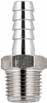
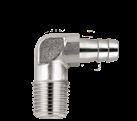

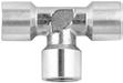
8.16 60-62 Series
62340
HOSE ADAPTER
MALE
62355
HOSE ADAPTER ELBOW 62360
CONNECTOR
TEE Part No. A A1 BSPT BCLCH 62340-6-1/861/8 .768(19,5).295(7,5)1.260(32).433(11) 62340-7-1/871/8 .768(19,5).295(7,5)1.260(32).433(11) 62340-7-1/471/4 .768(19,5).433(11)1.398(35,5).551(14) 62340-8-1/481/4 .768(19,5).433(11)1.398(35,5).551(14) 62340-9-1/491/4 .768(19,5).433(11)1.398(35,5).551(14) 62340-9-3/893/8 .768(19,5).453(11,5)1.417(36).669(17) 62340-10-1/4101/4 .768(19,5).433(11)1.398(35,5).551(14) 62340-10-3/8103/8 .768(19,5).453(11,5)1.417(36).669(17) 62340-10-1/2101/2 .768(19,5).551(14)1.535(39).866(22) 62340-12-1/4121/4 .768(19,5).433(11)1.398(35,5).551(14) 62340-12-3/8123/8 .768(19,5).453(11,5)1.417(36).669(17) 62340-12-1/2121/2 .768(19,5).551(14)1.535(39).866(22) 62340-14-3/8143/8 .768(19,5).453(11,5)1.417(36).669(17) 62340-14-1/2141/2 .768(19,5).551(14)1.535(39).866(22) 62340-16-1/2161/2 .768(19,5).551(14)1.535(39).866(22) 62340-18-1/2181/2 .768(19,5).551(14)1.535(39).866(22) 62340-18-3/4183/4 .768(19,5).650(16,5)1.713(43,5)1.063(27) 62340-20-1/2201/2 .768(19,5).551(14)1.535(39).866(22) 62340-20-3/4203/4 .768(19,5).531(13,5)1.575(40)1.063(27) A A1 B C L CH
No. A A1 BSPT BCDCH 623550044BS0061/8 .295(7,5).709(18).519(13,2).394(10) 623550044BT0061/4 .433(11).945(24).519(13,2).472(12) 623550044BZ0071/8 .295(7,5).709(18).519(13,2).394(10) 623550044BX0071/4 .433(11).945(24).519(13,2).472(12) 623550044CB0091/4 .433(11).945(24).519(13,2).472(12) A D A1 B C CH Part No.A BSPP BCDECH1CH2 62360-1/81/8 .649(16,5).354(9).551(14).157(4)0.866(22).748(19) 62360-1/41/4 .807(20,5).590(15).826(21).157(4)1.063(27).945(24) 62360-3/83/8 1.043(26,5).551(14).826(21).197(5)1.260(32)1.181(30) 62360-1/21/2 1.122(28,5).787(20)1.063(27).236(6)1.417(36)1.260(32) 62360-3/43/4 1.358(34,5).886(22,5)1.181(30).236(6)1.614(41)1.614(41) 62360-11” 1.673(42,5).964(24,5)1.338(34).315(8)1.968(50)1.811(46) B A E C D CH2 CH1 Part No.A BSPP BCL1L2CH 62400-1/81/8 .335(8,5).512(13)1.457(37).728(18,5).472(12) 62400-1/41/4 .433(11).650(16,5)1.929(49).965(24,5).472(12) 62400-3/83/8 .472(12).807(20,5)2.126(54)1.063(27).591(15) 62400-1/21/2 .591(15)1.004(25,5)2.520(64)1.260(32).787(20) B C L2 L1 A CH Page 118
MALE
BULKHEAD
62400 FEMALE
Part
62420
CENTRE LEG FEMALE TEE
62430
OFF SET MALE TEE
62440
MALE TEE
62450
MALE RUN TEE
Part No.A BSPP BB1CL1L2L3CH
62420-1/81/8 .295(7,5).335(8,5).512(13)1.417(36).728(18,5).708(18).472(12)
62420-1/41/4 .433(11).433(11).650(16,5)1.811(46).965(24,5).906(23).472(12)
62420-3/83/8 .453(11,5).472(12).807(20,5)2.007(51)1.141(29)1.004(25,5).591(15)
62420-1/21/2 .551(14).591(15)1.004(25,5)2.322(59)1.340(34)1.161(29,5).787(20)
62500
ELBOW M X M
Part No.A BSPP BB1CL1L2L3CH
62430-1/81/8 .295(7,5).335(8,5).512(13)1.437(36.5).708(18).708(18).472(12)
62430-1/41/4 .433(11).433(11).650(16,5)1.869(47.5).906(23).906(23).472(12)
62430-3/83/8 .453(11,5).472(12).807(20,5)2.067(52.5)1.083(27.5)1.004(25,5).591(15)
62430-1/21/2 .551(14).591(15)1.004(25,5)2.422(61.5)1.220(31.5)1.161(29,5).787(20)
Part No.A BSPPA1 BSPT BB1CL1L2CH
62440-1/81/81/8 .295(7,5).335(8,5).689(17,5)1.457(37).689(17,5).472(12)
62440-1/41/41/4 .433(11).433(11).906(23)1.929(49).906(23).472(12)
62440-3/83/83/8 .453(11,5).472(12)1.004(25,5)2.126(54)1.004(25,5).591(15)
62440-1/21/21/2 .551(14).591(15)1.161(29,5)2.52(64)1.161(29,5).787(20)
Part No.A BSPPA1 BSPT BB1CL1L2CH
62450-1/81/81/8 .295(7,5).335(8,5).728(18,5)1.417(36).728(18,5).472(12)
62450-1/41/41/4 .433(11).433(11).965(24,5)1.87(47,5).965(24,5).472(12)
62450-3/83/83/8 .453(11,5).472(12)1.063(27)2.067(52,5)1.063(27).591(15)
62450-1/21/21/2 .551(14).591(15)1.26(32)2.421(61,5)1.260(32).787(20)
62500-1/81/8 .295(7,5).709(18).394(10)
62500-1/41/4 .433(11).945(24).472(12)

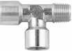
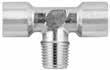
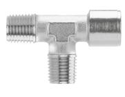
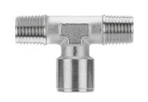
62500-3/83/8 .453(11,5)1.063(27).591(15)
62500-1/21/2 .551(14)1.161(29.5).787(20)
8.17 60-62 Series
L1 B C L2 L3 A B1 CH
L1 B B1 C L2 L3 A CH
L2 A1 L1 B1 B A C CH
CH A B1 B L1 C A1 L2
Part No. A BSPP BLCH
CH L B L A Page 119


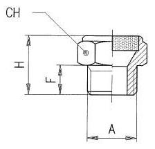

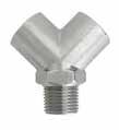
8.18 60-62 Series 62510 ELBOW FM X FM 62520 ELBOW ML X FM 62540 BREATHER VENT 62600 CENTRAL MALE Y 90° 62610 FEMALE Y 90° Part No. A BSPP CBLCH 62510-1/81/8 .512(13).335(8,5).827(21).394(10) 62510-1/41/4 .65(16,5).433(11)1.004(25,5).472(12) 62510-3/83/8 .807(20,5).472(12)1.102(28).591(15) 62510-1/21/2 1.004(25,5).591(15)1.260(32).787(20) CH A B L L C Part No. A BSPP A1 BSPT BB1CL1L2CH 62520-1/81/81/8 .295(7,5).335(8,5).827(21).709(18).827(21).394(10) 62520-1/41/41/4 .433(11).433(11)1.004(25,5).945(24)1.004(25,5).472(12) 62520-3/83/83/8 .453(11,5).472(12)1.102(28)1.063(27)1.102(28).591(15) 62520-1/21/21/2 .551(14).591(15)1.260(32)1.161(29,5)1.260(32).787(20) CH L2 A B1 B L1 A1 C Part No. A BSPP FHCH dB* 62540-1/81/8 .315(8).591(15).551(14) 73 62540-1/41/4 .315(8).591(15).669(17) 74 62540-3/83/8 .394(10).709(18).866(22) 86 62540-1/21/2 .472(12).866(22)1.063(27) 80 min max Temperature - 20 °C -4 °F + 300 °C 572 °F Bar Pressure 10 bar Filtration threshold 70 µm dB* Acustic fading at 6 bar Part No. A BSPP BB1LCH 62600-1/41/4 .433(11).433(11)1.457(37).669(17) 62600-3/83/8 .453(11,5).492(12.5)1.811(46).866(22) 62600-1/21/2 .551(14).65(16,5)2.285(58)1.023(26) 90° L B1 A B CH Part No. A BSPP BLCH 62610-1/41/4 .433(11)1.457(37).669(17) 62610-3/83/8 .433(11)1.811(46).866(22) 62610-1/21/2 .551(14)2.285(58)1.023(26) 90° B A CH L Page 120
Flow Regulators - Quick Exhaust Valves - Slide Valves - Unidirectional Valves Or Non Return Valves Block Valves


reserves the right to vary models and dimensions without notice

Aignep
Functional Series 82662 Pg.9.39 82850 82860 Pg.9.35 82830 Pg.9.30 82663 Pg.9.39 82835 Pg.9.30 82664 Pg.9.39 82880 82890 Pg.9.42-9.43 82670VM Pg.9.39 82660 Pg.9.37 82650 Pg.9.36 89000 Pag.9.6 88000 Pag.9.8 50000N Pag.9.10 85000 Pag.9.12 55000 Pag.9.14 88000 Pag.9.16 Functional Series PTF-SAE- EXTRA SHORT 89000 Pag.9.18 87000 Pag.9.20 50000N Pag.9.22 85000 Pag.9.24 55000 Pag.9.26 82000 Pag.9.28
85940 Pg.9.31 85960 Pg.9.33 85945 Pg.9.31 85950 Pg.9.32 85955 Pg.9.32 Page 121
FUNCTIONAL FITTINGS
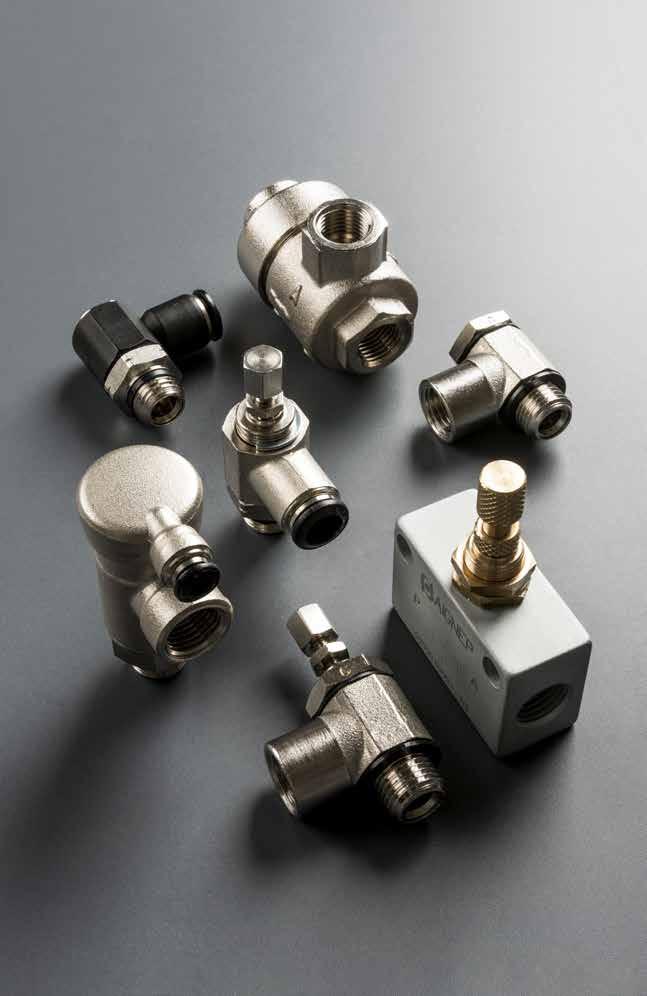
Functional Series
Page 122
F
TECHNICAL CHARACTERISTICS
Threads & Advantages
Component Parts and Materials
1 Nickel Plated Brass Adjustment Screw
2 NBR 70 O-Ring
3 303 Stainless Steel Shaft Clip
4 NBR 70 O-Ring
5 Nickel Plated Brass Body
Tubing Compatibility
Nylon 11
Nylon 12 Polyethylene Polyurethane
Advantages
The SWIFTFIT Universal Thread has been designed to offer the following advantages to the end users:
• Reduced overall length
• Smaller hex dimensions compared to parallel threads
• Fits with various parallel and tapered threads
Our SWIFTFIT universal fittings also work on non-flat surfaces without compromising an air-tight seal.
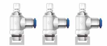
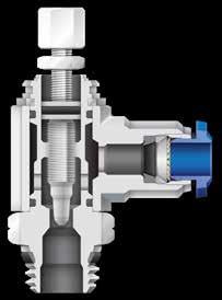
9.3 Flow Control Valves 1907/2006 2011/65/CE PED 2014/68/UE ISO 14743:2004
Reference Standard FLOW CONTROL VALVES 1 2 3 4 5
~ 250 PSI -0.99 bar ~ 20 bar -0.099 MPa ~ 2.0 MPa Bar
Air
Pressure Rating Vacuum
Media Compressed
Temperatures Rating NBR -4º F ~ 176º F -20º C ~ 80º C NPT NPTF Tapered ISO 228 BSP PF Parallell ISO 7 BSPT PT Tapered ISO 7 BSPP Parallell
Page 123
PTF Thread
Flow Control Valves
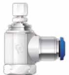
The PTF Thread has been designed to offer the following advantages to the end users:
Standard USA design. PTF/SAE extra short thread
• Designed for connections with an NPTF thread
• Dryseal pipe threads are designed for applications where clearance is not sufficient for the full thread length of NPTF threads.

9.4
Torque Specifications Recommended Torque Thread Size Min. Breaking torque 1/8 5 Nm 8 Nm 1/4 9 Nm 30 Nm Page 124
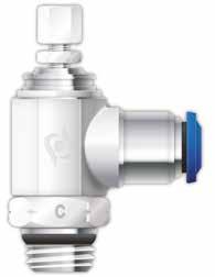
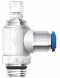
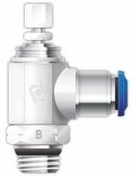
9.5
KEY ScrewAdjustKnobAdjust
FLOW OUT C PartNumber: 89953 - 89958 - 89903 - 89907 88953 - 88958 - 87903 - 87907 50901N - 50905N - 50903N - 50907N 85953 - 85958 - 85903 - 85907 55900 - 55905 - 55903 - 55907 88952 - 88957 - 82903 - 82907
FLOW IN V PartNumber: 89963 - 89968 - 89913 - 89917 88963 - 88968 - 87913 - 87917 50910N - 50915N - 50913N - 50917N 85963 - 85968 - 85913 - 85917 55910 - 55915 - 55913 - 55917 88962 - 88967 - 82913 - 82917
FLOW B PartNumber: 89973 - 89978 - 89923 - 89927 88973 - 88978 - 87923 - 87927 50920N - 50925N - 50923N - 50927N 85973 - 85978 - 85923 - 85927 55920 - 55925 - 55923 - 55927 88972 - 88977 - 82923 - 82927 Page 125
Flow Control Valves
CONTROLLED
CONTROLLED
BI-DIRECTIONAL
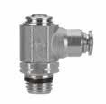
9.6
89953 INCH TUBE FLOW CONTROL (OUT) 89963 INCH TUBE FLOW CONTROL (IN) 89973 INCH TUBE NEEDLE VALVE Part No. TubeA BL1L2CHD 89953-02-321/810/32 .157(4).748(19).945(21).315(8).394(10) 89953-02-021/81/8 .217(5,5).827(21)1.181(30,5).551(14).394(10) 89953-53-325/3210/32 .157(4).748(19).945(21).315(8).394(10) 89953-53-025/321/8 .217(5,5).827(21)1.181(30,5).551(14).394(10) 89953-04-021/41/8 .217(5,5).866(22)1.181(30,5).551(14).492(12,5) 89953-04-041/41/4 .276(7).984(25)1.417(36).669(17).492(12,5) 89953-06-043/81/4 .295(7,5)1.181(30,5)1.614(41).787(20).689(17,5) 89953-06-063/83/8 .295(7,5)1.181(30,5)1.614(41).787(20).689(17,5) 89953-08-061/23/8 .295(7,5)1.280(32,5)1.614(41).787(20).846(21,5) 89953-08-081/21/2 .354(9)1.378(35)1.850(47).945(24).846(21,5) C L1 L2 CH B A D
No. TubeA BL1L2CHD 89963-02-321/810/32 .157(4).748(19).945(21).315(8).394(10) 89963-02-021/81/8 .217(5,5).827(21)1.181(30,5).551(14).394(10) 89963-53-325/3210/32 .157(4).748(19).945(21).315(8).394(10) 89963-53-025/321/8 .217(5,5).827(21)1.181(30,5).551(14).394(10) 89963-04-021/41/8 .217(5,5).866(22)1.181(30,5).551(14).492(12,5) 89963-04-041/41/4 .276(7).984(25)1.417(36).669(17).492(12,5) 89963-06-043/81/4 .295(7,5)1.181(30,5)1.614(41).787(20).689(17,5) 89963-06-063/83/8 .295(7,5)1.181(30,5)1.614(41).787(20).689(17,5) 89963-08-061/23/8 .295(7,5)1.280(32,5)1.614(41).787(20).846(21,5) 89963-08-081/21/2 .354(9)1.378(35)1.850(47).945(24).846(21,5) V L1 L2 CH B A D Part No. TubeA BL1L2CHD 89973-02-321/810/32 .157(4).748(19).945(21).315(8).394(10) 89973-02-021/81/8 .217(5,5).827(21)1.181(30,5).551(14).394(10) 89973-53-325/3210/32 .157(4).748(19).945(21).315(8).394(10) 89973-53-025/321/8 .217(5,5).827(21)1.181(30,5).551(14).394(10) 89973-04-021/41/8 .217(5,5).866(22)1.181(30,5).551(14).492(12,5) 89973-04-041/41/4 .276(7).984(25)1.417(36).669(17).492(12,5) 89973-06-043/81/4 .217(5,5)1.181(30,5)1.614(41).787(20).689(17,5) 89973-06-063/83/8 .217(5,5)1.181(30,5)1.614(41).787(20).689(17,5) 89973-08-061/23/8 .217(5,5)1.280(32,5)1.614(41).787(20).846(21,5) 89973-08-081/21/2 .354(9)1.378(35)1.850(47).945(24).846(21,5)
Flow Control Valves
Part
BL1 L2 CH B A D Page 126
89958
INCH TUBE FLOW CONTROL (OUT)
89968
INCH TUBE FLOW CONTROL (IN)
89978
INCH TUBE NEEDLE VALVE
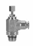
Part No. TubeA BL1L2minL2maxCHD
89958-02-321/810/32 .157(4).748(19)1.299(33)1.476(37,5).315(8).394(10)
89958-02-021/81/8 .217(5,5).827(21)1.614(41)1.830(46,5).551(14).394(10)
89958-53-325/3210/32 .157(4).748(19)1.299(33)1.472(37,5).315(8).394(10)
89958-53-025/321/8 .217(5,5).827(21)1.614(41)1.830(46,5).551(14).394(10)
89958-04-021/41/8 .217(5,5).866(22)1.614(41)1.830(46,5).551(14).492(12,5)
89958-04-041/41/4 .276(7).984(25)1.850(47)2.086(53).669(17).492(12,5)
89958-06-043/81/4 .295(7,5)1.181(30,5)2.205(56)2.480(63).787(20).689(17,5)
89958-06-063/83/8 .295(7,5)1.181(30,5)2.205(56)2.480(63).787(20).689(17,5)
89958-08-061/23/8 .295(7,5)1.280(32,5)2.205(56)2.480(63).787(20).846(21,5)
89958-08-081/21/2 .354(9)1.378(35)2.402(61)2.717(69).945(24).846(21,5)
Part No. TubeA
BL1L2minL2maxCHD
89968-02-321/810/32 .157(4).748(19)1.299(33)1.476(37,5).315(8).394(10)
89968-02-021/81/8 .217(5,5).827(21)1.614(41)1.830(46,5).551(14).394(10)
89968-53-325/3210/32 .157(4).748(19)1.299(33)1.472(37,5).315(8).394(10)
89968-53-025/321/8 .217(5,5).827(21)1.614(41)1.830(46,5).551(14).394(10)
89968-04-021/41/8 .217(5,5).866(22)1.614(41)1.830(46,5).551(14).492(12,5)
89968-04-041/41/4 .276(7).984(25)1.850(47)2.086(53).669(17).492(12,5)
89968-06-043/81/4 .295(7,5)1.181(30,5)2.205(56)2.480(63).787(20).689(17,5)
89968-06-063/83/8 .295(7,5)1.181(30,5)2.205(56)2.480(63).787(20).689(17,5)
89968-08-061/23/8 .295(7,5)1.280(32,5)2.205(56)2.480(63).787(20).846(21,5)
89968-08-081/21/2 .354(9)1.378(35)2.402(61)2.717(69).945(24).846(21,5)
Part No. TubeA
BL1L2minL2maxCHD
89978-02-321/810/32 .157(4).748(19)1.299(33)1.476(37,5).315(8).394(10)
89978-02-021/81/8 .217(5,5).827(21)1.614(41)1.830(46,5).551(14).394(10)
89978-53-325/3210/32 .157(4).748(19)1.299(33)1.472(37,5).315(8).394(10)
89978-53-025/321/8 .217(5,5).827(21)1.614(41)1.830(46,5).551(14).394(10)
89978-04-021/41/8 .217(5,5).866(22)1.614(41)1.830(46,5).551(14).492(12,5)
89978-04-041/41/4 .276(7).984(25)1.850(47)2.086(53).669(17).492(12,5)
89978-06-043/81/4 .295(7,5)1.181(30,5)2.205(56)2.480(63).787(20).689(17,5)
89978-06-063/83/8 .295(7,5)1.181(30,5)2.205(56)2.480(63).787(20).689(17,5)
89978-08-061/23/8 .295(7,5)1.280(32,5)2.205(56)2.480(63).787(20).846(21,5)
89978-08-081/21/2 .354(9)1.378(35)2.402(61)2.717(69).945(24).846(21,5)
9.7
Flow Control Valves
C L1 L2 CH B A D
V L1 L2 CH B A D
B L1 L2 CH B A D Page 127
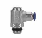
9.8
88953 INCH TUBE FLOW CONTROL (OUT) 88963 INCH TUBE FLOW CONTROL (IN) 88973 INCH TUBE NEEDLE VALVE Part No. TubeA BL1L2CHD 88953-02-321/810/32 .157(4).748(19).945(21).315(8).394(10) 88953-02-021/81/8 .217(5,5).827(21)1.181(30,5).551(14).394(10) 88953-53-325/3210/32 .157(4).748(19).945(21).315(8).394(10) 88953-53-025/321/8 .217(5,5).827(21)1.181(30,5).551(14).394(10) 88953-04-021/41/8 .217(5,5).866(22)1.181(30,5).551(14).492(12,5) 88953-04-041/41/4 .276(7).984(25)1.417(36).669(17).492(12,5) 88953-06-043/81/4 .295(7,5)1.181(30,5)1.614(41).787(20).689(17,5) 88953-06-063/83/8 .295(7,5)1.181(30,5)1.614(41).787(20).689(17,5) 88953-08-061/23/8 .295(7,5)1.280(32,5)1.614(41).787(20).846(21,5) 88953-08-081/21/2 .354(9)1.378(35)1.850(47).945(24).846(21,5) C L1 L2 CH B A D Part No. TubeA BL1L2CHD 88963-02-321/810/32 .157(4).748(19).945(21).315(8).394(10) 88963-02-021/81/8 .217(5,5).827(21)1.181(30,5).551(14).394(10) 88963-53-325/3210/32 .157(4).748(19).945(21).315(8).394(10) 88963-53-025/321/8 .217(5,5).827(21)1.181(30,5).551(14).394(10) 88963-04-021/41/8 .217(5,5).866(22)1.181(30,5).551(14).492(12,5) 88963-04-041/41/4 .276(7).984(25)1.417(36).669(17).492(12,5) 88963-06-043/81/4 .295(7,5)1.181(30,5)1.614(41).787(20).689(17,5) 88963-06-063/83/8 .295(7,5)1.181(30,5)1.614(41).787(20).689(17,5) 88963-08-061/23/8 .295(7,5)1.280(32,5)1.614(41).787(20).846(21,5) 88963-08-081/21/2 .354(9)1.378(35)1.850(47).945(24).846(21,5)
Flow Control Valves
VL1 L2 CH B A D Part No. TubeA BL1L2CHD 88973-02-321/810/32 .157(4).748(19).945(21).315(8).394(10) 88973-02-021/81/8 .217(5,5).827(21)1.181(30,5).551(14).394(10) 88973-53-325/3210/32 .157(4).748(19).945(21).315(8).394(10) 88973-53-025/321/8 .217(5,5).827(21)1.181(30,5).551(14).394(10) 88973-04-021/41/8 .217(5,5).866(22)1.181(30,5).551(14).492(12,5) 88973-04-041/41/4 .276(7).984(25)1.417(36).669(17).492(12,5) 88973-06-043/81/4 .295(7,5)1.181(30,5)1.614(41).787(20).689(17,5) 88973-06-063/83/8 .295(7,5)1.181(30,5)1.614(41).787(20).689(17,5) 88973-08-061/23/8 .295(7,5)1.280(32,5)1.614(41).787(20).846(21,5) 88973-08-081/21/2 .354(9)1.378(35)1.850(47).945(24).846(21,5)
BL1 L2 CH B A D Page 128
88958
INCH TUBE FLOW CONTROL (OUT)
88968
INCH TUBE FLOW CONTROL (IN)
88978
INCH TUBE NEEDLE VALVE
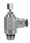
Part No. TubeA BL1L2minL2maxCHD
88958-02-321/810/32 .157(4).748(19)1.299(33)1.476(37,5).315(8).394(10)
88958-02-021/81/8 .217(5,5).827(21)1.614(41)1.830(46,5).551(14).394(10)
88958-53-325/3210/32 .157(4).748(19)1.299(33)1.472(37,5).315(8).394(10)
88958-53-025/321/8 .217(5,5).827(21)1.614(41)1.830(46,5).551(14).394(10)
88958-04-021/41/8 .217(5,5).866(22)1.614(41)1.830(46,5).551(14).492(12,5)
88958-04-041/41/4 .276(7).984(25)1.850(47)2.086(53).669(17).492(12,5)
88958-06-043/81/4 .295(7,5)1.181(30,5)2.205(56)2.480(63).787(20).689(17,5)
88958-06-063/83/8 .295(7,5)1.181(30,5)2.205(56)2.480(63).787(20).689(17,5)
88958-08-061/23/8 .295(7,5)1.280(32,5)2.205(56)2.480(63).787(20).846(21,5)
88958-08-081/21/2 .354(9)1.378(35)2.402(61)2.717(69).945(24).846(21,5)
Part No. TubeA BL1L2minL2maxCHD
88968-02-321/810/32 .157(4).748(19)1.299(33)1.476(37,5).315(8).394(10)
88968-02-021/81/8 .217(5,5).827(21)1.614(41)1.830(46,5).551(14).394(10)
V88968-53-325/3210/32 .157(4).748(19)1.299(33)1.476(37,5).315(8).394(10)
88968-53-025/321/8 .217(5,5).827(21)1.614(41)1.830(46,5).551(14).394(10)
88968-04-021/41/8 .217(5,5).866(22)1.614(41)1.830(46,5).551(14).492(12,5)
88968-04-041/41/4 .276(7).984(25)1.850(47)2.086(53).669(17).492(12,5)
88968-06-043/81/4 .295(7,5)1.181(30,5)2.205(56)2.480(63).787(20).689(17,5)
88968-06-063/83/8 .295(7,5)1.181(30,5)2.205(56)2.480(63).787(20).689(17,5)
88968-08-061/23/8 .295(7,5)1.280(32,5)2.205(56)2.480(63).787(20).846(21,5)
88968-08-081/21/2 .354(9)1.378(35)2.205(56)2.717(69).945(24).846(21,5)
Part No. TubeA
BL1L2minL2maxCHD
88978-02-321/810/32 .157(4).748(19)1.299(33)1.476(37,5).315(8).394(10)
88978-02-021/81/8 .217(5,5).827(21)1.614(41)1.830(46,5).551(14).394(10)
88978-53-325/3210/32 .157(4).748(19)1.299(33)1.472(37,5).315(8).394(10)
88978-53-025/321/8 .217(5,5).827(21)1.614(41)1.830(46,5).551(14).394(10)
88978-04-021/41/8 .217(5,5).866(22)1.614(41)1.830(46,5).551(14).492(12,5)
88978-04-041/41/4 .276(7).984(25)1.850(47)2.086(53).669(17).492(12,5)
88978-06-043/81/4 .295(7,5)1.181(30,5)2.205(56)2.480(63).787(20).689(17,5)
88978-06-063/83/8 .295(7,5)1.181(30,5)2.205(56)2.480(63).787(20).689(17,5)
88978-08-061/23/8 .295(7,5)1.280(32,5)2.205(56)2.480(63).787(20).846(21,5)
88978-08-081/21/2 .354(9)1.378(35)2.402(61)2.717(69).945(24).846(21,5)
9.9
Flow Control Valves
C L1 L2 CH B A D
L1 L2 CH B A D
B L1 L2 CH B A D Page 129
Flow Control Valves
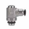
50901N
METRIC TUBE FLOW CONTROL (OUT)
50910N
METRIC TUBE FLOW CONTROL (IN)
50920N
METRIC TUBE NEEDLE VALVE
Part No.
9.10
Part No. TubeA BL1L2CHD 50901N-3-M53M5 .157(4).748(19)1.161(29,5).315(8).394(10) 50901N-4-M5 5/32 (4) M5 .157(4).748(19)1.161(29,5).315(8).394(10) 50901N-4-1/8 5/32 (4) 1/8 .217(5,5).827(21)1.220(31).551(14).394(10) 50901N-5-M55M5 .157(4).787(20)1.161(29,5).315(8).492(12,5) 50901N-5-1/851/8 .217(5,5).846(21,5)1.220(31).551(14).492(12,5) 50901N-5-1/451/4 .276(7).965(24,5)1.437(36,5).669(17).492(12,5) 50901N-6-M56M5 .157(4).807(20,5)1.161(29,5).315(8).492(12,5) 50901N-6-1/861/8 .217(5,5).886(22,5)1.220(31).551(14).492(12,5) 50901N-6-1/461/4 .276(7).984(25)1.437(36,5).669(17).492(12,5) 50901N-8-1/8 5/16 (8) 1/8 .217(5,5).945(24)1.220(31).551(14).551(14) 50901N-8-1/4 5/16 (8) 1/4 .276(7)1.024(26)1.437(36,5).669(17).551(14) 50901N-8-3/8 5/16 (8) 3/8 .295(7,5)1.122(28,5)1.673(42,5).787(20).551(14) 50901N-10-1/4101/4 .276(7)1.122(28,5)1.437(36,5).669(17).669(17) 50901N-10-3/8103/8 .295(7,5)1.201(30,5)1.673(42,5).787(20).669(17) 50901N-12-3/8123/8 .295(7,5)1.280(32,5)1.673(42,5).787(20).846(21,5) 50901N-12-1/2121/2 .354(9)1.378(35)1.850(47).945(24).846(21,5) 50901N-14-1/2141/2 .354(9)1.398(35,5)1.850(47).945(24).846(21,5) C L1 L2 CH B A D
TubeA BL1L2CHD 50910N-3-M53M5 .157(4).748(19)1.161(29,5).315(8).394(10) 50910N-4-M5 5/32 (4) M5 .157(4).748(19)1.161(29,5).315(8).394(10) 50910N-4-1/8 5/32 (4) 1/8 .217(5,5).827(21)1.220(31).551(14).394(10) 50910N-5-M55M5 .157(4).787(20)1.161(29,5).315(8).492(12,5) 50910N-5-1/851/8 .217(5,5).846(21,5)1.220(31).551(14).492(12,5) 50910N-5-1/451/4 .276(7).965(24,5)1.437(36,5).669(17).492(12,5) 50910N-6-M56M5 .157(4).807(20,5)1.161(29,5).315(8).492(12,5) 50910N-6-1/861/8 .217(5,5).886(22,5)1.220(31).551(14).492(12,5) 50910N-6-1/461/4 .276(7).984(25)1.437(36,5).669(17).492(12,5) 50910N-8-1/8 5/16 (8) 1/8 .217(5,5).945(24)1.220(31).551(14).551(14) 50910N-8-1/4 5/16 (8) 1/4 .276(7)1.024(26)1.437(36,5).669(17).551(14) 50910N-8-3/8 5/16 (8) 3/8 .295(7,5)1.122(28,5)1.673(42,5).787(20).551(14) 50910N-10-1/4101/4 .276(7)1.122(28,5)1.437(36,5).669(17).669(17) 50910N-10-3/8103/8 .295(7,5)1.201(30,5)1.673(42,5).787(20).669(17) 50910N-12-3/8123/8 .295(7,5)1.280(32,5)1.673(42,5).787(20).846(21,5) 50910N-12-1/2121/2 .354(9)1.378(35)1.850(47).945(24).846(21,5) 50910N-14-1/2141/2 .354(9)1.398(35,5)1.850(47).945(24).846(21,5) V L1 L2 CH B A D Part No. TubeA BL1L2CHD 50920N-3-M53M5 .157(4).748(19)1.161(29,5).315(8).394(10) 50920N-4-M5 5/32 (4) M5 .157(4).748(19)1.161(29,5).315(8).394(10) 50920N-4-1/8 5/32 (4) 1/8 .217(5,5).827(21)1.220(31).551(14).394(10) 50920N-5-M55M5 .157(4).787(20)1.161(29,5).315(8).492(12,5) 50920N-5-1/851/8 .217(5,5).846(21,5)1.220(31).551(14).492(12,5) 50920N-5-1/451/4 .276(7).965(24,5)1.437(36,5).669(17).492(12,5) 50920N-6-M56M5 .157(4).807(20,5)1.161(29,5).315(8).492(12,5) 50920N-6-1/861/8 .217(5,5).886(22,5)1.220(31).551(14).492(12,5) 50920N-6-1/461/4 .276(7).984(25)1.437(36,5).669(17).492(12,5) 50920N-8-1/8 5/16 (8) 1/8 .217(5,5).945(24)1.220(31).551(14).551(14) 50920N-8-1/4 5/16 (8) 1/4 .276(7)1.024(26)1.437(36,5).669(17).551(14) 50920N-8-3/8 5/16 (8) 3/8 .295(7,5)1.122(28,5)1.673(42,5).787(20).551(14) 50920N-10-1/4101/4 .276(7)1.122(28,5)1.437(36,5).669(17).669(17) 50920N-10-3/8103/8 .295(7,5)1.201(30,5)1.673(42,5).787(20).669(17) 50920N-12-3/8123/8 .295(7,5)1.280(32,5)1.673(42,5).787(20).846(21,5) 50920N-12-1/2121/2 .354(9)1.378(35)1.850(47).945(24).846(21,5) 50920N-14-1/2141/2 .354(9)1.398(35,5)1.850(47).945(24).846(21,5) B L1 L2 CH B A D Page 130
50905N
METRIC TUBE FLOW CONTROL (OUT)
50915N
METRIC TUBE FLOW CONTROL (IN)
50925N
METRIC TUBE NEEDLE VALVE
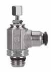
Part No. TubeA BL1L2minL2maxCHD
50905N-3-M53M5 .157(4).748(19)1.516(38,5)1.673(42,5).315(8).394(10)
50905N-4-M5 5/32 (4) M5 .157(4).748(19)1.516(38,5)1.673(42,5).315(8).394(10)
50905N-4-1/8 5/32 (4) 1/8 .217(5,5).827(21)1.732(44)1.929(49).551(14).394(10)
50905N-5-M55M5 .157(4).787(20)1.516(38,5)1.673(42,5).315(8).492(12,5)
50905N-5-1/851/8 .217(5,5).846(21,5)1.732(44)1.929(49).551(14).492(12,5)
50905N-5-1/451/4 .276(7).965(24,5)1.909(48,5)2.165(55).669(17).492(12,5)
50905N-6-M56M5 .157(4).807(20,5)1.516(38,5)1.673(42,5).315(8).492(12,5)
50905N-6-1/861/8 .217(5,5).886(22,5)1.732(44)1.929(49).551(14).492(12,5)
50905N-6-1/461/4 .276(7).984(25)1.909(48,5)2.165(55).669(17).492(12,5)
50905N-10-1/4101/4 .276(7)1.122(28,5)1.909(48,5)2.165(55).669(17).669(17)
50905N-10-3/8103/8 .295(7,5)1.201(30,5)2.205(56)2.559(65).787(20).669(17)
50905N-12-3/8123/8 .295(7,5)1.280(32,5)2.205(56)2.559(65).787(20).846(21,5)
50905N-12-1/2121/2 .354(9)1.378(35)2.441(62)2.717(69).945(24).846(21,5)
50905N-14-1/2141/2 .354(9)1.398(35,5)2.441(62)2.717(69).945(24).846(21,5)
Part No. TubeA
BL1L2minL2maxCHD
50915N-3-M53M5 .157(4).748(19)1.516(38,5)1.673(42,5).315(8).394(10)
50915N-4-M5 5/32 (4) M5 .157(4).748(19)1.516(38,5)1.673(42,5).315(8).394(10)
50915N-4-1/8 5/32 (4) 1/8 .217(5,5).827(21)1.732(44)1.929(49).551(14).394(10)
50915N-5-M55M5 .157(4).787(20)1.516(38,5)1.673(42,5).315(8).492(12,5)
50915N-5-1/851/8 .217(5,5).846(21,5)1.732(44)1.929(49).551(14).492(12,5)
50915N-5-1/451/4 .276(7).965(24,5)1.909(48,5)2.165(55).669(17).492(12,5)
50915N-6-M56M5 .157(4).807(20,5)1.516(38,5)1.673(42,5).315(8).492(12,5)
50915N-6-1/861/8 .217(5,5).886(22,5)1.732(44)1.929(49).551(14).492(12,5)
50915N-6-1/461/4 .276(7).984(25)1.909(48,5)2.165(55).669(17).492(12,5)
.217(5,5).945(24)1.732(44)1.929(49).551(14).551(14)
50915N-10-3/8103/8 .295(7,5)1.201(30,5)2.205(56)2.559(65).787(20).669(17)
50915N-12-3/8123/8 .295(7,5)1.280(32,5)2.205(56)2.559(65).787(20).846(21,5)
50915N-12-1/2121/2 .354(9)1.378(35)2.441(62)2.717(69).945(24).846(21,5)
50915N-14-1/2141/2 .354(9)1.398(35,5)2.441(62)2.717(69).945(24).846(21,5)
Part No. TubeA
BL1L2minL2maxCHD
50925N-3-M53M5 .157(4).748(19)1.516(38,5)1.673(42,5).315(8).394(10)
50925N-4-M5 5/32 (4) M5 .157(4).748(19)1.516(38,5)1.673(42,5).315(8).394(10)
50925N-4-1/8 5/32 (4) 1/8 .217(5,5).827(21)1.732(44)1.929(49).551(14).394(10)
50925N-5-M55M5 .157(4).787(20)1.516(38,5)1.673(42,5).315(8).492(12,5)
50925N-5-1/851/8 .217(5,5).846(21,5)1.732(44)1.929(49).551(14).492(12,5)
50925N-5-1/451/4 .276(7).965(24,5)1.909(48,5)2.165(55).669(17).492(12,5)
50925N-6-M56M5 .157(4).807(20,5)1.516(38,5)1.673(42,5).315(8).492(12,5)
50925N-6-1/861/8 .217(5,5).886(22,5)1.732(44)1.929(49).551(14).492(12,5)
50925N-6-1/461/4 .276(7).984(25)1.909(48,5)2.165(55).669(17).492(12,5)
50925N-8-1/8
.217(5,5).945(24)1.732(44)1.929(49).551(14).551(14)
50925N-10-3/8103/8 .295(7,5)1.201(30,5)2.205(56)2.559(65).787(20).669(17)
50925N-12-3/8123/8 .295(7,5)1.280(32,5)2.205(56)2.559(65).787(20).846(21,5)
50925N-12-1/2121/2 .354(9)1.378(35)2.441(62)2.717(69).945(24).846(21,5)
50925N-14-1/2141/2 .354(9)1.398(35,5)2.441(62)2.717(69).945(24).846(21,5)
9.11
Flow Control Valves
50905N-8-1/8 5/16 (8) 1/8 .217(5,5).945(24)1.732(44)1.929(49).551(14).551(14) 50905N-8-1/4 5/16 (8) 1/4 .276(7)1.024(26)1.909(48,5)2.165(55).669(17).551(14) 50905N-8-3/8 5/16 (8) 3/8 .295(7,5)1.122(28,5)2.205(56)2.559(65).787(20).551(14)
C L1 L2 CH B A D
50915N-8-1/8 5/16 (8) 1/8
50915N-8-1/4 5/16 (8) 1/4
5/16 (8) 3/8
.276(7)1.024(26)1.909(48,5)2.165(55).669(17).551(14) 50915N-8-3/8
.295(7,5)1.122(28,5)2.205(56)2.559(65).787(20).551(14) 50915N-10-1/4101/4 .276(7)1.122(28,5)1.909(48,5)2.165(55).669(17).669(17)
V L1 L2 CH B A D
5/16
5/16 (8) 1/4
5/16 (8) 3/8
(8) 1/8
50925N-8-1/4
.276(7)1.024(26)1.909(48,5)2.165(55).669(17).551(14) 50925N-8-3/8
.295(7,5)1.122(28,5)2.205(56)2.559(65).787(20).551(14) 50925N-10-1/4101/4 .276(7)1.122(28,5)1.909(48,5)2.165(55).669(17).669(17)
B L1 L2 CH B A D Page 131
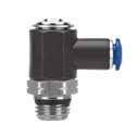
9.12
INCH TUBE FLOW CONTROL (OUT) 85963 INCH TUBE FLOW CONTROL (IN)
INCH TUBE NEEDLE VALVE C Part No. TubeA BL1L2CHD 85953-02-321/810/32 .157(4).748(19).945(21).315(8).394(10) 85953-02-021/81/8 .217(5,5).827(21)1.181(30,5).551(14).394(10) 85953-53-325/3210/32 .157(4).748(19).945(21).315(8).394(10) 85953-53-025/321/8 .217(5,5).827(21)1.181(30,5).551(14).394(10) 85953-04-021/41/8 .217(5,5).866(22)1.181(30,5).551(14).472(12) 85953-04-041/41/4 .276(7).984(25)1.417(36).669(17).472(12) 85953-06-043/81/4 .295(7,5)1.181(30,5)1.614(41).787(20).669(17) 85953-06-063/83/8 .295(7,5)1.181(30,5)1.614(41).787(20).669(17) 85953-08-061/23/8 .295(7,5)1.280(32,5)1.614(41).787(20).787(20) 85953-08-081/21/2 .354(9)1.378(35)1.850(47).945(24).787(20) CH L2 B A L1 D V Part No. TubeA BL1L2CHD 85963-02-321/810/32 .157(4).748(19).945(21).315(8).394(10) 85963-02-021/81/8 .217(5,5).827(21)1.181(30,5).551(14).394(10) 85963-53-325/3210/32 .157(4).748(19).945(21).315(8).394(10) 85963-53-025/321/8 .217(5,5).827(21)1.181(30,5).551(14).394(10) 85963-04-021/41/8 .217(5,5).866(22)1.181(30,5).551(14).472(12) 85963-04-041/41/4 .276(7).984(25)1.417(36).669(17).472(12) 85963-06-043/81/4 .295(7,5)1.181(30,5)1.614(41).787(20).669(17) 85963-06-063/83/8 .295(7,5)1.181(30,5)1.614(41).787(20).669(17) 85963-08-061/23/8 .295(7,5)1.280(32,5)1.614(41).787(20).787(20) 85963-08-081/21/2 .354(9)1.378(35)1.850(47).945(24).787(20) A L2 B CH L1 D B Part No. TubeA BL1L2CHD 85973-02-321/810/32 .157(4).748(19).945(21).315(8).394(10) 85973-02-021/81/8 .217(5,5).827(21)1.181(30,5).551(14).394(10) 85973-53-325/3210/32 .157(4).748(19).945(21).315(8).394(10) 85973-53-025/321/8 .217(5,5).827(21)1.181(30,5).551(14).394(10) 85973-04-021/41/8 .217(5,5).866(22)1.181(30,5).551(14).472(12) 85973-04-041/41/4 .276(7).984(25)1.417(36).669(17).472(12) 85973-06-043/81/4 .295(7,5)1.181(30,5)1.614(41).787(20).669(17) 85973-06-063/83/8 .295(7,5)1.181(30,5)1.614(41).787(20).669(17) 85973-08-061/23/8 .295(7,5)1.280(32,5)1.614(41).787(20).787(20) 85973-08-081/21/2 .354(9)1.378(35)1.850(47).945(24).787(20) A L2 B CH L1 D Page 132
Flow Control Valves 85953
85973
85958
INCH TUBE FLOW CONTROL (OUT)
85968
INCH TUBE FLOW CONTROL (IN)
85978
INCH TUBE NEEDLE VALVE
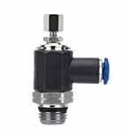
B
Part No. TubeA BL1L2minL2maxCHD
85958-02-321/810/32 .157(4).748(19)1.299(33)1.476(37,5).315(8).394(10)
85958-02-021/81/8 .217(5,5).827(21)1.614(41)1.830(46,5).551(14).394(10)
85958-53-325/3210/32 .157(4).748(19)1.299(33)1.472(37,5).315(8).394(10)
85958-53-025/321/8 .217(5,5).827(21)1.614(41)1.830(46,5).551(14).394(10)
85958-04-021/41/8 .217(5,5).866(22)1.614(41)1.830(46,5).551(14).472(12)
85958-04-041/41/4 .276(7).984(25)1.850(47)2.086(53).669(17).472(12)
85958-06-043/81/4 .295(7,5)1.181(30,5)2.205(56)2.480(63).787(20).669(17)
85958-06-063/83/8 .295(7,5)1.181(30,5)2.205(56)2.480(63).787(20).669(17)
85958-08-061/23/8 .295(7,5)1.280(32,5)2.205(56)2.480(63).787(20).787(20)
85958-08-081/21/2 .354(9)1.378(35)2.402(61)2.717(69).945(24).787(20)
Part No. TubeA
BL1L2minL2maxCHD
85968-02-321/810/32 .157(4).748(19)1.299(33)1.476(37,5).315(8).394(10)
85968-02-021/81/8 .217(5,5).827(21)1.614(41)1.830(46,5).551(14).394(10)
85968-53-325/3210/32 .157(4).748(19)1.299(33)1.476(37,5).315(8).394(10)
85968-53-025/321/8 .217(5,5).827(21)1.614(41)1.830(46,5).551(14).394(10)
85968-04-021/41/8 .217(5,5).866(22)1.614(41)1.830(46,5).551(14).472(12)
85968-04-041/41/4 .276(7).984(25)1.850(47)2.086(53).669(17).472(12)
85968-06-043/81/4 .295(7,5)1.181(30,5)2.205(56)2.480(63).787(20).669(17)
85968-06-063/83/8 .295(7,5)1.181(30,5)2.205(56)2.480(63).787(20).669(17)
85968-08-061/23/8 .295(7,5)1.280(32,5)2.205(56)2.480(63).787(20).787(20)
85968-08-081/21/2 .354(9)1.378(35)2.205(56)2.717(69).945(24).787(20)
Part No. TubeA BL1L2minL2maxCHD
85978-02-321/810/32 .157(4).748(19)1.299(33)1.476(37,5).315(8).394(10)
85978-02-021/81/8 .217(5,5).827(21)1.614(41)1.830(46,5).551(14).394(10)
85978-53-325/3210/32 .157(4).748(19)1.299(33)1.472(37,5).315(8).394(10)
85978-53-025/321/8 .217(5,5).827(21)1.614(41)1.830(46,5).551(14).394(10)
85978-04-021/41/8 .217(5,5).866(22)1.614(41)1.830(46,5).551(14).472(12)
85978-04-041/41/4 .276(7).984(25)1.850(47)2.086(53).669(17).472(12)
85978-06-043/81/4 .295(7,5)1.181(30,5)2.205(56)2.480(63).787(20).669(17)
85978-06-063/83/8 .295(7,5)1.181(30,5)2.205(56)2.480(63).787(20).669(17)
85978-08-061/23/8 .295(7,5)1.280(32,5)2.205(56)2.480(63).787(20).787(20)
85978-08-081/21/2 .354(9)1.378(35)2.402(61)2.717(69).945(24).787(20)
9.13
Flow Control Valves
C
A L2 B CH L1 D V
A L2 B CH L1 D
A L2 B CH L1 D Page 133
Flow Control Valves
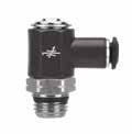
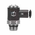
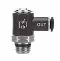
55901
METRIC TUBE FLOW CONTROL (OUT)
55910
METRIC TUBE FLOW CONTROL (IN)
55920
METRIC TUBE NEEDLE VALVE
9.14
Part No. TubeA BL1L2CHD 55901-4-M5 5/32 (4) M5 .217(5,5).768(19,5)1.161(29,5).315(8).394(10) 55901-4-1/8 5/32 (4) 1/8 .217(5,5).846(21,5)1.220(31).551(14).394(10) 55901-5-M55M5 .217(5,5).807(20,5)1.161(29,5).315(8).492(12,5) 55901-5-1/851/8 .217(5,5).886(22,5)1.220(31).551(14).492(12,5) 55901-5-1/451/4 .276(7).984(25)1.437(36,5).669(17).492(12,5) 55901-6-M56M5 .217(5,5).827(21)1.161(29,5).315(8).492(12,5) 55901-6-1/861/8 .217(5,5).906(23)1.220(31).551(14).492(12,5) 55901-6-1/461/4 .276(7)1.004(25,5)1.437(36,5).669(17).492(12,5) 55901-8-1/8 5/16 (8) 1/8 .217(5,5).925(23,5)1.220(31).551(14).551(14) 55901-8-1/4 5/16 (8) 1/4 .276(7)1.024(26)1.437(36,5).669(17).551(14) 55901-8-3/8 5/16 (8) 3/8 .335(8,5)1.083(27,5)1.673(42,5).787(20).551(14) 55901-10-3/8103/8 .335(8,5)1.201(30,5)1.673(42,5).787(20).669(17) 55901-12-3/8123/8 .335(8,5)1.280(32,5)1.673(42,5).787(20).846(21,5) 55901-12-1/2121/2 .394(10)1.378(35)1.850(47).945(24).846(21,5) C CH L2 B A L1 D Part No. TubeA BL1L2CHD 55910-4-M5 5/32 (4) M5 .217(5,5).768(19,5)1.161(29,5).315(8).394(10) 55910-4-1/8 5/32 (4) 1/8 .217(5,5).846(21,5)1.220(31).551(14).394(10) 55910-5-M55M5 .217(5,5).807(20,5)1.161(29,5).315(8).492(12,5) 55910-5-1/851/8 .217(5,5).886(22,5)1.220(31).551(14).492(12,5) 55910-5-1/451/4 .276(7).984(25)1.437(36,5).669(17).492(12,5) 55910-6-M56M5 .217(5,5).827(21)1.161(29,5).315(8).492(12,5) 55910-6-1/861/8 .217(5,5).906(23)1.220(31).551(14).492(12,5) 55910-6-1/461/4 .276(7)1.004(25,5)1.437(36,5).669(17).492(12,5) 55910-8-1/8 5/16 (8) 1/8 .217(5,5).925(23,5)1.220(31).551(14).551(14) 55910-8-1/4 5/16 (8) 1/4 .276(7)1.024(26)1.437(36,5).669(17).551(14) 55910-8-3/8 5/16 (8) 3/8 .335(8,5)1.083(27,5)1.673(42,5).787(20).551(14) 55910-10-3/8103/8 .335(8,5)1.201(30,5)1.673(42,5).787(20).669(17) 55910-12-3/8123/8 .335(8,5)1.280(32,5)1.673(42,5).787(20).846(21,5) 55910-12-1/2121/2 .394(10)1.378(35)1.850(47).945(24).846(21,5)
A L2 B CH L1 D Part No. TubeA BL1L2CHD 55920-4-M5 5/32 (4) M5 .217(5,5).768(19,5)1.161(29,5).315(8).394(10) 55920-4-1/8 5/32 (4) 1/8 .217(5,5).846(21,5)1.220(31).551(14).394(10) 55920-5-M55M5 .217(5,5).807(20,5)1.161(29,5).315(8).492(12,5) 55920-5-1/851/8 .217(5,5).886(22,5)1.220(31).551(14).492(12,5) 55920-5-1/451/4 .276(7).984(25)1.437(36,5).669(17).492(12,5) 55920-6-M56M5 .217(5,5).827(21)1.161(29,5).315(8).492(12,5) 55920-6-1/861/8 .217(5,5).906(23)1.220(31).551(14).492(12,5) 55920-6-1/461/4 .276(7)1.004(25,5)1.437(36,5).669(17).492(12,5) 55920-8-1/8 5/16 (8) 1/8 .217(5,5).925(23,5)1.220(31).551(14).551(14) 55920-8-1/4 5/16 (8) 1/4 .276(7)1.024(26)1.437(36,5).669(17).551(14) 55920-8-3/8 5/16 (8) 3/8 .335(8,5)1.083(27,5)1.673(42,5).787(20).551(14) 55920-10-3/8103/8 .335(8,5)1.201(30,5)1.673(42,5).787(20).669(17) 55920-12-3/8123/8 .335(8,5)1.280(32,5)1.673(42,5).787(20).846(21,5) 55920-12-1/2121/2 .394(10)1.378(35)1.850(47).945(24).846(21,5) B A L2 B CH L1 D Page 134
V
55905
METRIC TUBE FLOW CONTROL (OUT)
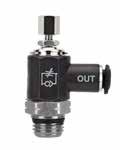
55915
METRIC TUBE FLOW CONTROL (IN)
55925
METRIC TUBE NEEDLE VALVE
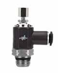
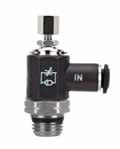
55905-4-M5 5/32 (4) M5 .217(5,5).768(19,5)1.516(38,5)1.673(42,5).315(8).394(10)
55905-4-1/8 5/32 (4) 1/8 .217(5,5).846(21,5)1.732(44)1.929(49).551(14).394(10)
55905-5-M55M5 .217(5,5).807(20,5)1.516(38,5)1.673(42,5).315(8).492(12,5)
55905-5-1/851/8 .217(5,5).886(22,5)1.732(44)1.929(49).551(14).492(12,5)
55905-5-1/451/4 .276(7).984(25)1.909(48,5)2.165(55).669(17).492(12,5)
55905-6-M56M5 .217(5,5).827(21)1.516(38,5)1.673(42,5).315(8).492(12,5)
55905-6-1/861/8 .217(5,5).906(23)1.732(44)1.929(49).551(14).492(12,5)
55905-6-1/461/4 .276(7)1.004(25,5)1.909(48,5)2.165(55).669(17).492(12,5)
.217(5,5).925(23,5)1.732(44)1.929(49).551(14).551(14)
55905-12-1/2121/2 .394(10)1.378(35)2.441(62)2.717(69).945(24).846(21,5)
Part
55915-4-1/8 5/32 (4) 1/8 .217(5,5).846(21,5)1.732(44)1.929(49).551(14).394(10)
55915-5-M55M5 .217(5,5).807(20,5)1.516(38,5)1.673(42,5).315(8).492(12,5)
55915-5-1/851/8 .217(5,5).886(22,5)1.732(44)1.929(49).551(14).492(12,5)
55915-5-1/451/4 .276(7).984(25)1.909(48,5)2.165(55).669(17).492(12,5)
55915-6-M56M5 .217(5,5).827(21)1.516(38,5)1.673(42,5).315(8).492(12,5)
55915-6-1/861/8 .217(5,5).906(23)1.732(44)1.929(49).551(14).492(12,5) 55915-6-1/461/4 .276(7)1.004(25,5)1.909(48,5)2.165(55).669(17).492(12,5)
.217(5,5).925(23,5)1.732(44)1.929(49).551(14).551(14)
Part No. TubeA BL1L2minL2maxCHD
55925-4-M5 5/32 (4) M5 .217(5,5).768(19,5)1.516(38,5)1.673(42,5).315(8).394(10)
55925-4-1/8 5/32 (4) 1/8 .217(5,5).846(21,5)1.732(44)1.929(49).551(14).394(10)
55925-5-M55M5 .217(5,5).807(20,5)1.516(38,5)1.673(42,5).315(8).492(12,5)
55925-5-1/851/8 .217(5,5).886(22,5)1.732(44)1.929(49).551(14).492(12,5)
55925-5-1/451/4 .276(7).984(25)1.909(48,5)2.165(55).669(17).492(12,5)
55925-6-M56M5 .217(5,5).827(21)1.516(38,5)1.673(42,5).315(8).492(12,5)
55925-6-1/861/8 .217(5,5).906(23)1.732(44)1.929(49).551(14).492(12,5)
55925-6-1/461/4 .276(7)1.004(25,5)1.909(48,5)2.165(55).669(17).492(12,5)
.217(5,5).925(23,5)1.732(44)1.929(49).551(14).551(14)
9.15
Flow Control Valves
No. TubeA
Part
BL1L2minL2maxCHD
5/16 (8) 1/8
55905-8-1/4 5/16 (8) 1/4
55905-8-3/8 5/16 (8) 3/8 .335(8,5)1.083(27,5)2.205(56)2.559(65).787(20).551(14) 55905-10-3/8103/8
55905-8-1/8
.276(7)1.024(26)1.909(48,5)2.165(55).669(17).551(14)
.335(8,5)1.201(30,5)2.205(56)2.559(65).787(20).669(17) 55905-12-3/8123/8 .335(8,5)1.280(32,5)2.205(56)2.559(65).787(20).846(21,5)
C A L2 B CH L1 D
No. TubeA
55915-4-M5 5/32 (4) M5 .217(5,5).768(19,5)1.516(38,5)1.673(42,5).315(8).394(10)
BL1L2minL2maxCHD
55915-8-1/8 5/16 (8) 1/8
55915-8-1/4 5/16 (8) 1/4 .276(7)1.024(26)1.909(48,5)2.165(55).669(17).551(14) 55915-8-3/8 5/16 (8) 3/8 .335(8,5)1.083(27,5)2.205(56)2.559(65).787(20).551(14) 55915-10-3/8103/8 .335(8,5)1.201(30,5)2.205(56)2.559(65).787(20).669(17) 55915-12-3/8123/8 .335(8,5)1.280(32,5)2.205(56)2.559(65).787(20).846(21,5) 55915-12-1/2121/2 .394(10)1.378(35)2.441(62)2.717(69).945(24).846(21,5) V A L2 B CH L1 D
5/16 (8) 1/8
5/16 (8) 1/4
55925-8-3/8 5/16 (8) 3/8 .335(8,5)1.083(27,5)2.205(56)2.559(65).787(20).551(14) 55925-10-3/8103/8 .335(8,5)1.201(30,5)2.205(56)2.559(65).787(20).669(17) 55925-12-3/8123/8
B A L2 B CH L1 D Page 135
55925-8-1/8
55925-8-1/4
.276(7)1.024(26)1.909(48,5)2.165(55).669(17).551(14)
.335(8,5)1.280(32,5)2.205(56)2.559(65).787(20).846(21,5) 55925-12-1/2121/2 .394(10)1.378(35)2.441(62)2.717(69).945(24).846(21,5)
FEMALE
FEMALE
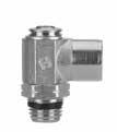
9.16
Flow Control Valves 88952
NPTF
(OUT)
FLOW CONTROL
88962
CONTROL (IN)
FEMALE NPTF FLOW
88972
NPTF NEEDLE VALVE Part No.F NPTF A BL1L2CH 88952-32-32 10/32 UNF 10/32 .157(4).394(10).945(24).315(8) 88952-02-021/8 1/8 .217(5,5).650(16,5)1.181(30,5).551(14) 88952-04-041/4 1/4 .276(7).866(22)1.417(36).669(17) 88952-06-063/8 3/8 .295(7,5)1.043(26,5)1.614(26,5).787(20) C F A L1 B L2 CH V Part No.F NPTF A BL1L2CH 88962-32-32 10/32 UNF 10/32 .157(4).394(10).945(24).315(8) 88962-02-021/8 1/8 .217(5,5).650(16,5)1.181(30,5).551(14) 88962-04-041/4 1/4 .276(7).866(22)1.417(36).669(17) 88962-06-063/8 3/8 .295(7,5)1.043(26,5)1.614(26,5).787(20) F A L1 B L2 CH B Part No.F NPTF A BL1L2CH 88972-32-32 10/32 UNF 10/32 .157(4).394(10).945(24).315(8) 88972-02-021/8 1/8 .217(5,5).650(16,5)1.181(30,5).551(14) 88972-04-041/4 1/4 .276(7).866(22)1.417(36).669(17) 88972-06-063/8 3/8 .295(7,5)1.043(26,5)1.614(26,5).787(20) F A L1 B L2 CH Page 136
88957
88967
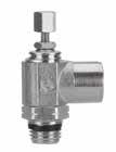
88977
FEMALE
9.17
Flow Control Valves
(OUT)
FEMALE NPTF FLOW CONTROL
CONTROL (IN)
FEMALE NPTF FLOW
NPTF
VALVE C
No.F NPTF A BL1L2minL2maxCH 88957-32-32 10/32 UNF 10/32 .157(4).394(10)1.299(33)1.477(37,5).315(8) 88957-02-021/8 1/8 .217(5,5).650(16,5)1.614(41)1.830(46,5).551(14) 88957-04-041/4 1/4 .276(7).866(22)1.850(47)2.086(53).669(17) 88957-06-063/8 3/8 .295(7,5)1.043(26,5)2.480(63)2.480(63).787(20) F A L1 B L2 CH V
No.F NPTF A BL1L2minL2maxCH 88967-32-32 10/32 UNF 10/32 .157(4).394(10)1.299(33)1.477(37,5).315(8) 88967-02-021/8 1/8 .217(5,5).650(16,5)1.614(41)1.830(46,5).551(14) 88967-04-041/4 1/4 .276(7).866(22)1.850(47)2.086(53).669(17) 88967-06-063/8 3/8 .295(7,5)1.043(26,5)2.205(56)2.480(63).787(20) F A L1 B L2 CH B
No.F NPTF A BL1L2minL2maxCH 88977-32-32 10/32 UNF 10/32 .157(4).394(10)1.299(33)1.477(37,5).315(8) 88977-02-021/8 1/8 .217(5,5).650(16,5)1.614(41)1.830(46,5).551(14) 88977-04-041/4 1/4 .276(7).866(22)1.850(47)2.086(53).669(17) 88977-06-063/8 3/8 .295(7,5)1.043(26,5)2.480(63)2.480(63).787(20) F A L1 B L2 CH Page 137
NEEDLE
Part
Part
Part
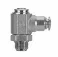
9.18
89903 INCH TUBE FLOW CONTROL (OUT) 89913 INCH TUBE FLOW CONTROL (IN) 89923 INCH TUBE NEEDLE VALVE Part No. Tube A (PTF) BL1L2CHD 89903-02-021/81/8 .240(6,1).827(21)1.181(30,5).551(14).394(10) 89903-53-025/321/8 .240(6,1).827(21)1.181(30,5).551(14).394(10) 89903-04-021/41/8 .240(6,1).866(22)1.181(30,5).551(14).492(12,5) 89903-04-041/41/4 .358(9,1).984(25)1.417(36).669(17).492(12,5) 89903-06-043/81/4 .358(9,1)1.181(30,5)1.614(41).787(20).689(17,5) C PTF L1 L2 CH B A D Part No. Tube A (PTF) BL1L2CHD 89913-02-021/81/8 .240(6,1).827(21)1.181(30,5).551(14).394(10) 89913-53-025/321/8 .240(6,1).827(21)1.181(30,5).551(14).394(10) 89913-04-021/41/8 .240(6,1).866(22)1.181(30,5).551(14).492(12,5) 89913-04-041/41/4 .358(9,1).984(25)1.417(36).669(17).492(12,5) 89913-06-043/81/4 .358(9,1)1.181(30,5)1.614(41).787(20).689(17,5) V PTF L1 L2 CH B A D Part No. Tube A (PTF) BL1L2CHD 89923-02-021/81/8 .240(6,1).827(21)1.181(30,5).551(14).394(10) 89923-53-025/321/8 .240(6,1).827(21)1.181(30,5).551(14).394(10) 89923-04-021/41/8 .240(6,1).866(22)1.181(30,5).551(14).492(12,5) 89923-04-041/41/4 .358(9,1).984(25)1.417(36).669(17).492(12,5) 89923-06-043/81/4 .358(9,1)1.181(30,5)1.614(41).787(20).689(17,5) B PTF L1 L2 CH B A D Page 138
Flow Control Valves
89907
INCH TUBE FLOW CONTROL (OUT)
89917
INCH TUBE FLOW CONTROL (IN)
89927
INCH TUBE NEEDLE VALVE
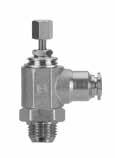
PTF
Part No. Tube A (PTF) BL1L2minL2maxCHD
89907-02-021/81/8 .240(6,1).827(21)1.614(41)1.830(46,5).551(14).394(10)
89907-53-025/321/8 .240(6,1).827(21)1.614(41)1.830(46,5).551(14).394(10)
89907-04-021/41/8 .240(6,1).866(22)1.614(41)1.830(46,5).551(14).492(12,5)
89907-04-041/41/4 .358(9,1).984(25)1.850(47)2.086(53).669(17).492(12,5)
89907-06-043/81/4 .358(9,1)1.181(30,5)2.205(56)2.480(63).787(20).689(17,5)
Part No. Tube A (PTF) BL1L2minL2maxCHD
89917-02-021/81/8 .240(6,1).827(21)1.614(41)1.830(46,5).551(14).394(10)
89917-53-025/321/8 .240(6,1).827(21)1.614(41)1.830(46,5).551(14).394(10)
89917-04-021/41/8 .240(6,1).866(22)1.614(41)1.830(46,5).551(14).492(12,5)
89917-04-041/41/4 .358(9,1).984(25)1.850(47)2.086(53).669(17).492(12,5)
89917-06-043/81/4 .358(9,1)1.181(30,5)2.205(56)2.480(63).787(20).689(17,5)
Part No. Tube A (PTF) BL1L2minL2maxCHD
89927-02-021/81/8 .240(6,1).827(21)1.614(41)1.830(46,5).551(14).394(10)
89927-53-025/321/8 .240(6,1).827(21)1.614(41)1.830(46,5).551(14).394(10)
89927-04-021/41/8 .240(6,1).866(22)1.614(41)1.830(46,5).551(14).492(12,5)
89927-04-041/41/4 .358(9,1).984(25)1.850(47)2.086(53).669(17).492(12,5)
89927-06-043/81/4 .358(9,1)1.181(30,5)2.205(56)2.480(63).787(20).689(17,5)
9.19
Flow Control Valves
C PTF L1 L2 CH B A D
PTF L1 L2 CH B A D
V
B
L1 L2 CH B A D Page 139
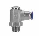
9.20
87903 INCH TUBE FLOW CONTROL (OUT) 87913 INCH TUBE FLOW CONTROL (IN) 87923 INCH TUBE NEEDLE VALVE Part No. Tube A (PTF) BL1L2CHD 87903-02-021/81/8 .240(6,1).827(21)1.181(30,5).551(14).394(10) 87903-53-025/321/8 .240(6,1).827(21)1.181(30,5).551(14).394(10) 87903-04-021/41/8 .240(6,1).866(22)1.181(30,5).551(14).492(12,5) 87903-04-041/41/4 .358(9,1).984(25)1.417(36).669(17).492(12,5) 87903-06-043/81/4 .358(9,1)1.181(30,5)1.614(41).787(20).689(17,5) C PTF L1 L2 CH B A D Part No. Tube A (PTF) BL1L2CHD 87913-02-021/81/8 .240(6,1).827(21)1.181(30,5).551(14).394(10) 87913-53-025/321/8 .240(6,1).827(21)1.181(30,5).551(14).394(10) 87913-04-021/41/8 .240(6,1).866(22)1.181(30,5).551(14).492(12,5) 87913-04-041/41/4 .358(9,1).984(25)1.417(36).669(17).492(12,5) 87913-06-043/81/4 .358(9,1)1.181(30,5)1.614(41).787(20).689(17,5) V PTF L1 L2 CH B A D PTF Part No. Tube A (PTF) BL1L2CHD 87923-02-021/81/8 .240(6,1).827(21)1.181(30,5).551(14).394(10) 87923-53-025/321/8 .240(6,1).827(21)1.181(30,5).551(14).394(10) 87923-04-021/41/8 .240(6,1).866(22)1.181(30,5).551(14).492(12,5) 87923-04-041/41/4 .358(9,1).984(25)1.417(36).669(17).492(12,5) 87923-06-043/81/4 .358(9,1)1.181(30,5)1.614(41).787(20).689(17,5) B L1 L2 CH B A D Page 140
Flow Control Valves
87907
INCH TUBE FLOW CONTROL (OUT)
87917
INCH TUBE FLOW CONTROL (IN)
87927
INCH TUBE NEEDLE VALVE
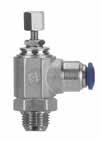
PTF
Part No. Tube A (PTF) BL1L2minL2maxCHD
87907-02-021/81/8 .240(6,1).827(21)1.614(41)1.830(46,5).551(14).394(10)
87907-53-025/321/8 .240(6,1).827(21)1.614(41)1.830(46,5).551(14).394(10)
87907-04-021/41/8 .240(6,1).866(22)1.614(41)1.830(46,5).551(14).492(12,5)
87907-04-041/41/4 .358(9,1).984(25)1.850(47)2.086(53).669(17).492(12,5)
87907-06-043/81/4 .358(9,1)1.181(30,5)2.205(56)2.480(63).787(20).689(17,5)
Part No. Tube A (PTF) BL1L2minL2maxCHD
87917-02-021/81/8 .240(6,1).827(21)1.614(41)1.830(46,5).551(14).394(10)
87917-53-025/321/8 .240(6,1).827(21)1.614(41)1.830(46,5).551(14).394(10)
V87917-04-021/41/8 .240(6,1).866(22)1.614(41)1.830(46,5).551(14).492(12,5)
87917-04-041/41/4 .358(9,1).984(25)1.850(47)2.086(53).669(17).492(12,5)
87917-06-043/81/4 .358(9,1)1.181(30,5)2.205(56)2.480(63).787(20).689(17,5)
Part No. Tube A (PTF) BL1L2minL2maxCHD 87927-02-021/81/8 .240(6,1).827(21)1.614(41)1.830(46,5).551(14).394(10)
87927-53-025/321/8 .240(6,1).827(21)1.614(41)1.830(46,5).551(14).394(10)
87927-04-021/41/8 .240(6,1).866(22)1.614(41)1.830(46,5).551(14).492(12,5)
87927-04-041/41/4 .358(9,1).984(25)1.850(47)2.086(53).669(17).492(12,5)
87927-06-043/81/4 .358(9,1)1.181(30,5)2.205(56)2.480(63).787(20).689(17,5)
9.21
Flow Control Valves
C PTF L1 L2 CH B A D
PTF L1 L2 CH B A D
B
L1 L2 CH B A D Page 141
Flow Control Valves
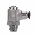
50903N
METRIC TUBE FLOW CONTROL (OUT)
50913N
METRIC TUBE FLOW CONTROL (IN)
50923N
METRIC TUBE NEEDLE VALVE
9.22
Part No. Tube A (PTF) BL1L2CHD 50903N-4-1/8 5/32 (4) 1/8 .240(6,1).827(21)1.220(31).551(14).394(10) 50903N-5-1/851/8 .240(6,1).846(21,5)1.220(31).551(14).492(12,5) 50903N-5-1/451/4 .358(9,1).965(24,5)1.437(36,5).669(17).492(12,5) 50903N-6-1/861/8 .240(6,1).886(22,5)1.220(31).551(14).492(12,5) 50903N-6-1/461/4 .358(9,1).984(25)1.437(36,5).669(17).492(12,5) 50903N-8-1/8 5/16 (8) 1/8 .240(6,1).945(24)1.220(31).551(14).551(14) 50903N-8-1/4 5/16 (8) 1/4 .358(9,1)1.024(26)1.437(36,5).669(17).551(14) C PTF L1 L2 CH B A D Part No. Tube A (PTF) BL1L2CHD 50913N-4-1/8 5/32 (4) 1/8 .240(6,1).827(21)1.220(31).551(14).394(10) 50913N-5-1/851/8 .240(6,1).846(21,5)1.220(31).551(14).492(12,5) 50913N-5-1/451/4 .358(9,1).965(24,5)1.437(36,5).669(17).492(12,5) 50913N-6-1/861/8 .240(6,1).886(22,5)1.220(31).551(14).492(12,5) 50913N-6-1/461/4 .358(9,1).984(25)1.437(36,5).669(17).492(12,5) 50913N-8-1/8 5/16 (8) 1/8 .240(6,1).945(24)1.220(31).551(14).551(14) 50913N-8-1/4 5/16 (8) 1/4 .358(9,1)1.024(26)1.437(36,5).669(17).551(14) V PTF L1 L2 CH B A D Part No. Tube A (PTF) BL1L2CHD 50923N-4-1/8 5/32 (4) 1/8 .240(6,1).827(21)1.220(31).551(14).394(10) 50923N-5-1/851/8 .240(6,1).846(21,5)1.220(31).551(14).492(12,5) 50923N-5-1/451/4 .358(9,1).965(24,5)1.437(36,5).669(17).492(12,5) 50923N-6-1/861/8 .240(6,1).886(22,5)1.220(31).551(14).492(12,5) 50923N-6-1/461/4 .358(9,1).984(25)1.437(36,5).669(17).492(12,5) 50923N-8-1/8 5/16 (8) 1/8 .240(6,1).945(24)1.220(31).551(14).551(14) 50923N-8-1/4 5/16 (8) 1/4 .358(9,1)1.024(26)1.437(36,5).669(17).551(14) B PTF L1 L2 CH B A D Page 142
50907N
METRIC TUBE FLOW CONTROL (OUT)
50907N-5-1/851/8 .240(6,1).846(21,5)1.732(44)1.929(49).551(14).492(12,5)
50907N-5-1/451/4 .358(9,1).965(24,5)1.909(48,5)2.165(55).669(17).492(12,5)
50907N-6-1/861/8 .240(6,1).886(22,5)1.732(44)1.929(49).551(14).492(12,5)
50907N-6-1/461/4 .358(9,1).984(25)1.909(48,5)2.165(55).669(17).492(12,5)
50917N
METRIC TUBE FLOW CONTROL (IN)
50927N
METRIC TUBE NEEDLE VALVE
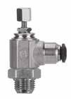
BL1L2minL2maxCHD
50917N-4-1/8 5/32 (4) 1/8 .240(6,1).827(21)1.732(44)1.929(49).551(14).394(10)
50917N-5-1/851/8 .240(6,1).846(21,5)1.732(44)1.929(49).551(14).492(12,5)
50917N-5-1/451/4 .358(9,1).965(24,5)1.909(48,5)2.165(55).669(17).492(12,5)
50917N-6-1/861/8 .240(6,1).886(22,5)1.732(44)1.929(49).551(14).492(12,5)
50917N-6-1/461/4 .358(9,1).984(25)1.909(48,5)2.165(55).669(17).492(12,5)
50917N-8-1/8
50917N-8-1/4
50927N-5-1/851/8 .240(6,1).846(21,5)1.732(44)1.929(49).551(14).492(12,5)
50927N-5-1/451/4 .358(9,1).965(24,5)1.909(48,5)2.165(55).669(17).492(12,5)
50927N-6-1/861/8 .240(6,1).886(22,5)1.732(44)1.929(49).551(14).492(12,5)
50927N-6-1/461/4 .358(9,1).984(25)1.909(48,5)2.165(55).669(17).492(12,5)
50927N-8-1/8 5/16 (8) 1/8 .240(6,1).945(24)1.732(44)1.929(49).551(14).551(14)
50927N-8-1/4 5/16 (8) 1/4 .358(9,1)1.024(26)1.909(48,5)2.165(55).669(17).551(14)
9.23
Flow Control Valves
No. Tube A (PTF) BL1L2minL2maxCHD 50907N-4-1/8 5/32 (4) 1/8 .240(6,1).827(21)1.732(44)1.929(49).551(14).394(10)
Part
5/16 (8) 1/8 .240(6,1).945(24)1.732(44)1.929(49).551(14).551(14) 50907N-8-1/4 5/16 (8) 1/4 .358(9,1)1.024(26)1.909(48,5)2.165(55).669(17).551(14) C PTF L1 L2 CH B A D
50907N-8-1/8
Part No. Tube A (PTF)
5/16 (8) 1/8
.240(6,1).945(24)1.732(44)1.929(49).551(14).551(14)
5/16 (8) 1/4
V PTF L1 L2 CH B A D Part No. Tube A (PTF) BL1L2minL2maxCHD
5/32 (4) 1/8
.358(9,1)1.024(26)1.909(48,5)2.165(55).669(17).551(14)
50927N-4-1/8
.240(6,1).827(21)1.732(44)1.929(49).551(14).394(10)
B PTF L1 L2 CH B A D Page 143
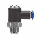
9.24
85903 INCH TUBE FLOW CONTROL (OUT) 85913 INCH TUBE FLOW CONTROL (IN) 85923 INCH TUBE NEEDLE VALVE PTF C Part No. Tube A (PTF) BL1L2CHD 85903-02-021/81/8 .240(6,1).827(21)1.181(30,5).551(14).394(10) 85903-53-025/321/8 .240(6,1).827(21)1.181(30,5).551(14).394(10) 85903-04-021/41/8 .240(6,1).866(22)1.181(30,5).551(14).472(12) 85903-04-041/41/4 .358(9,1).984(25)1.417(36).669(17).472(12) 85903-06-043/81/4 .358(9,1)1.181(30,5)1.614(41).787(20).669(17) L1 L2 CH B A D V Part No. Tube A (PTF) BL1L2CHD 85913-02-021/81/8 .240(6,1).827(21)1.181(30,5).551(14).394(10) 85913-53-025/321/8 .240(6,1).827(21)1.181(30,5).551(14).394(10) 85913-04-021/41/8 .240(6,1).866(22)1.181(30,5).551(14).472(12) 85913-04-041/41/4 .358(9,1).984(25)1.417(36).669(17).472(12) 85913-06-043/81/4 .358(9,1)1.181(30,5)1.614(41).787(20).669(17) PTF L1 L2 CH B A D
Flow Control Valves
BPart No. Tube A (PTF) BL1L2CHD 85923-02-021/81/8 .240(6,1).827(21)1.181(30,5).551(14).394(10) 85923-53-025/321/8 .240(6,1).827(21)1.181(30,5).551(14).394(10) 85923-04-021/41/8 .240(6,1).866(22)1.181(30,5).551(14).472(12) 85923-04-041/41/4 .358(9,1).984(25)1.417(36).669(17).472(12) 85923-06-043/81/4 .358(9,1)1.181(30,5)1.614(41).787(20).669(17) PTF L1 L2 CH B A D Page 144
85907
INCH TUBE FLOW CONTROL (OUT)
85917
INCH TUBE FLOW CONTROL (IN)
PTF
85927
INCH TUBE NEEDLE VALVE
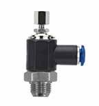
PTF
Part No. Tube A (PTF) BL1L2minL2maxCHD
85907-02-021/81/8 .240(6,1).827(21)1.614(41)1.830(46,5).551(14).394(10)
85907-53-025/321/8 .240(6,1).827(21)1.614(41)1.830(46,5).551(14).394(10)
85907-04-021/41/8 .240(6,1).866(22)1.614(41)1.830(46,5).551(14).472(12)
85907-04-041/41/4 .358(9,1).984(25)1.850(47)2.086(53).669(17).472(12)
85907-06-043/81/4 .358(9,1)1.181(30,5)2.205(56)2.480(63).787(20).669(17)
Part No. Tube A (PTF) BL1L2minL2maxCHD
85917-02-021/81/8 .240(6,1).827(21)1.614(41)1.830(46,5).551(14).394(10)
85917-53-025/321/8 .240(6,1).827(21)1.614(41)1.830(46,5).551(14).394(10)
85917-04-021/41/8 .240(6,1).866(22)1.614(41)1.830(46,5).551(14).472(12)
85917-04-041/41/4 .358(9,1).984(25)1.850(47)2.086(53).669(17).472(12)
85917-06-043/81/4 .358(9,1)1.181(30,5)2.205(56)2.480(63).787(20).669(17)
Part No. Tube A (PTF) BL1L2minL2maxCHD
85927-02-021/81/8 .240(6,1).827(21)1.614(41)1.830(46,5).551(14).394(10)
85927-53-025/321/8 .240(6,1).827(21)1.614(41)1.830(46,5).551(14).394(10)
85927-04-021/41/8 .240(6,1).866(22)1.614(41)1.830(46,5).551(14).472(12)
85927-04-041/41/4 .358(9,1).984(25)1.850(47)2.086(53).669(17).472(12)
85927-06-043/81/4 .358(9,1)1.181(30,5)2.205(56)2.480(63).787(20).669(17)
9.25
Flow Control Valves
C
PTF L1 L2 CH B A D V
L1 L2 CH B A D B
L1 L2 CH B A D Page 145
55903
METRIC TUBE FLOW CONTROL (OUT)
55913
METRIC TUBE FLOW CONTROL (IN)

55923
9.26
Flow Control Valves
Part No. Tube A (PTF) BL1L2CHD 55903-4-1/8 5/32 (4) 1/8 .240(6,1).846(21,5)1.220(31).551(14).394(10) 55903-5-1/851/8 .240(6,1).886(22,5)1.220(31).551(14).492(12,5) 55903-5-1/451/4 .358(9,1).984(25)1.437(36,5).669(17).492(12,5) 55903-6-1/861/8 .240(6,1).906(23)1.220(31).551(14).492(12,5) 55903-6-1/461/4 .358(9,1)1.004(25,5)1.437(36,5).669(17).492(12,5) 55903-8-1/8 5/16 (8) 1/8 .240(6,1).925(23,5)1.220(31).551(14).551(14) 55903-8-1/4 5/16 (8) 1/4 .358(9,1)1.024(26)1.437(36,5).669(17).551(14) C PTF L1 L2 CH B A D Part No. Tube A (PTF) BL1L2CHD 55913-4-1/8 5/32 (4) 1/8 .240(6,1).846(21,5)1.220(31).551(14).394(10) 55913-5-1/851/8 .240(6,1).886(22,5)1.220(31).551(14).492(12,5) 55913-5-1/451/4 .358(9,1).984(25)1.437(36,5).669(17).492(12,5) 55913-6-1/861/8 .240(6,1).906(23)1.220(31).551(14).492(12,5) 55913-6-1/461/4 .358(9,1)1.004(25,5)1.437(36,5).669(17).492(12,5) 55913-8-1/8 5/16 (8) 1/8 .240(6,1).925(23,5)1.220(31).551(14).551(14) 55913-8-1/4 5/16 (8) 1/4 .358(9,1)1.024(26)1.437(36,5).669(17).551(14) V PTF L1 L2 CH B A D Part No. Tube A (PTF) BL1L2CHD 55923-4-1/8 5/32 (4) 1/8 .240(6,1).846(21,5)1.220(31).551(14).394(10) 55923-5-1/851/8 .240(6,1).886(22,5)1.220(31).551(14).492(12,5) 55923-5-1/451/4 .358(9,1).984(25)1.437(36,5).669(17).492(12,5) 55923-6-1/861/8 .240(6,1).906(23)1.220(31).551(14).492(12,5) 55923-6-1/461/4 .358(9,1)1.004(25,5)1.437(36,5).669(17).492(12,5) 55923-8-1/8 5/16 (8) 1/8 .240(6,1).925(23,5)1.220(31).551(14).551(14) 55923-8-1/4 5/16 (8) 1/4 .358(9,1)1.024(26)1.437(36,5).669(17).551(14)
PTF L1 L2 CH B A D Page 146
METRIC TUBE NEEDLE VALVE
B
55907
METRIC TUBE FLOW CONTROL (OUT)
55907-5-1/851/8 .240(6,1).886(22,5)1.732(44)1.929(49).551(14).492(12,5)
55907-5-1/451/4 .358(9,1).984(25)1.909(48,5)2.165(55).669(17).492(12,5)
55907-6-1/861/8 .240(6,1).906(23)1.732(44)1.929(49).551(14).492(12,5)
55907-6-1/461/4 .358(9,1)1.004(25,5)1.909(48,5)2.165(55).669(17).492(12,5)
55917
METRIC TUBE FLOW CONTROL (IN)
55927
METRIC TUBE NEEDLE VALVE
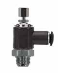
.240(6,1).846(21,5)1.732(44)1.929(49).551(14).394(10) 55917-5-1/851/8 .240(6,1).886(22,5)1.732(44)1.929(49).551(14).492(12,5)
55917-5-1/451/4 .358(9,1).984(25)1.909(48,5)2.165(55).669(17).492(12,5)
55917-6-1/861/8 .240(6,1).906(23)1.732(44)1.929(49).551(14).492(12,5)
55917-6-1/461/4 .358(9,1)1.004(25,5)1.909(48,5)2.165(55).669(17).492(12,5)
BL1L2minL2maxCHD
55927-4-1/8 5/32 (4) 1/8 .240(6,1).846(21,5)1.732(44)1.929(49).551(14).394(10)
55927-5-1/851/8 .240(6,1).886(22,5)1.732(44)1.929(49).551(14).492(12,5)
55927-5-1/451/4 .358(9,1).984(25)1.909(48,5)2.165(55).669(17).492(12,5)
55927-6-1/861/8 .240(6,1).906(23)1.732(44)1.929(49).551(14).492(12,5)
55927-6-1/461/4 .358(9,1)1.004(25,5)1.909(48,5)2.165(55).669(17).492(12,5) 55927-8-1/8
.358(9,1)1.024(26)1.909(48,5)2.165(55).669(17).551(14)
.240(6,1).925(23,5)1.732(44)1.929(49).551(14).551(14) 55927-8-1/4
9.27
Flow Control Valves
Part No. Tube A (PTF) BL1L2minL2maxCHD 55907-4-1/8 5/32 (4) 1/8 .240(6,1).846(21,5)1.732(44)1.929(49).551(14).394(10)
55907-8-1/8 5/16 (8) 1/8 .240(6,1).925(23,5)1.732(44)1.929(49).551(14).551(14) 55907-8-1/4 5/16 (8) 1/4 .358(9,1)1.024(26)1.909(48,5)2.165(55).669(17).551(14) C PTF L1 L2 CH B A D PTF Part No. Tube A (PTF) BL1L2minL2maxCHD 55917-4-1/8
5/32 (4) 1/8
55917-8-1/8 5/16 (8) 1/8
55917-8-1/4 5/16 (8) 1/4 .358(9,1)1.024(26)1.909(48,5)2.165(55).669(17).551(14) V L1 L2 CH B A D PTF Part No. Tube A (PTF)
.240(6,1).925(23,5)1.732(44)1.929(49).551(14).551(14)
5/16 (8) 1/8
5/16 (8) 1/4
B L1 L2 CH B A D Page 147
82903
FEMALE NPTF FLOW CONTROL (OUT)
82913
FEMALE NPTF FLOW CONTROL (IN)
82923
FEMALE
NEEDLE VALVE
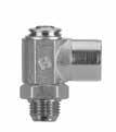
9.28
Flow Control Valves
Part No.F NPTFA (PTF) BL1L2CH 82903-02-021/8 1/8 .240(6,1).650(16,5)1.181(30,5).551(14) 82903-04-041/4 1/4 .358(9,1).866(22)1.417(36).669(17) C PTF F A L1 B L2 CH V Part No.F NPTFA (PTF) BL1L2CH 82913-02-021/8 1/8 .240(6,1).650(16,5)1.181(30,5).551(14) 82913-04-041/4 1/4 .358(9,1).866(22)1.417(36).669(17) PTF F A L1 B L2 CH B Part No.F NPTFA (PTF) BL1L2CH 82923-02-021/8 1/8 .240(6,1).650(16,5)1.181(30,5).551(14) 82923-04-041/4 1/4 .358(9,1).866(22)1.417(36).669(17) PTF F A L1 B L2 CH Page 148
NPTF
82907
FEMALE NPTF FLOW CONTROL (OUT)
82917
FEMALE NPTF FLOW CONTROL (IN)
82927
FEMALE NPTF NEEDLE VALVE
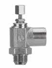
9.29
Flow Control Valves
PTF C Part No.F NPTFA (PTF) BL1L2minL2maxCH 82907-02-021/8 1/8 .240(6,1).650(16,5)1.614(41)1.830(46,5).551(14) 82907-04-041/4 1/4 .358(9,1).866(22)1.850(47)2.086(53).669(17) F A L1 B L2 CH V Part No.F NPTFA (PTF) BL1L2minL2maxCH 82917-02-021/8 1/8 .240(6,1).650(16,5)1.614(41)1.830(46,5).551(14) 82917-04-041/4 1/4 .358(9,1).866(22)1.850(47)2.086(53).669(17) PTF F A L1 B L2 CH B Part No.F NPTFA (PTF) BL1L2minL2maxCH 82927-02-021/8 1/8 .240(6,1).650(16,5)1.614(41)1.830(46,5).551(14) 82927-04-041/4 1/4 .358(9,1).866(22)1.850(47)2.086(53).669(17) PTF F A L1 B L2 CH Page 149
82815
INLINE FLOW CONTROL
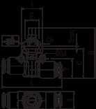

82820
INLINE FLOW CONTROL MALE X TUBE
82830
INLINE TUBE NEEDLE VALVE
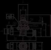
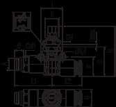
82835
INLINE NEEDLE VALVE MALE X TUBE
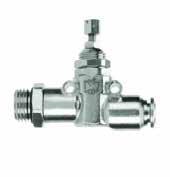
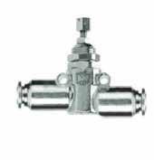
9.30
Flow Control Valves
Part No. Tube CDEFGHminHmaxILCH 82815-04 1/4 .928(23,5).157(4)M11X1.618(15,5).551(14)1.578(40,5)1.827(46,5).677(17)1.890(48).512(13) 82815-063/8 .996(25,5).177(4,5)M16X1.807(20,5).807(20,5)1.929(49)2.161(55).787(20)2.272(57,5).709(18) Part No. ATube BCDEFGHminHmaxIL1L2CHCH1 82820-04-04 1/41/4 .276(7).928(23,5).157(4)M11X1.618(15,5).551(14)1.578(40,5)1.827(46,5).677(17)1.169(29,5).945(24).512(13).512(13) 82820-06-041/43/8 .276(7).996(25,5).177(4,5)M16X1.807(20,5).807(20,5)1.929(49)2.161(55).787(20)1.378(35)1.134(29).709(18).630(13) 82820-06-063/83/8 .295(7,5).996(25,5).177(4,5)M16X1.807(20,5).807(20,5)1.929(49)2.161(55).787(20)1.299(33)1.134(29).709(18).669(17) Part No. Tube CDEFGHminHmaxILCH 82830-04 1/4 .928(23,5).157(4)M11X1.618(15,5).551(14)1.578(40,5)1.827(46,5).677(17)1.890(48).512(13) 82830-063/8 .996(25,5).177(4,5)M16X1.807(20,5).807(20,5)1.929(49)2.161(55).787(20)2.272(57,5).709(18) Part No. ATube BCDEFGHminHmaxIL1L2CHCH1 82835-04-04 1/41/4 .276(7).928(23,5).157(4)M11X1.618(15,5).551(14)1.578(40,5)1.827(46,5).677(17)1.169(29,5).945(24).512(13).512(13) 82835-06-063/83/8 .295(7,5).996(25,5).177(4,5)M16X1.807(20,5).807(20,5)1.929(49)2.161(55).787(20)1.299(33)1.134(29).709(18).669(17) Page 150
85940
TUBE IN-LINE NEEDLE VALVE (UNIDIRECTIONAL FLOW)

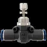
Part No. Tube CDEFGHILCH
85940-53 5/32 (4) .709(18).157(4)M12x1.571(14,5).598(15)1.476(37.5)÷1.712(43.5).709(18)2.046(52).551(14)
85940-041/4 .709(18).236(6)M12x1.571(14,5).598(15)1.476(37.5)÷1.712(43.5).709(18)2.046(52).551(14)
85940-05 5/16 (8) .787(20).256(6,5)M14x1.658(16,5).677(17)1.555(39.5)÷1,791(45.5).787(20)2.292(58).630(16)
85940-063/8 .928(23,5).315(8)M16x1.767(19,5).749(19)1.870(47.5)÷2.106(53.5).887(22,5)2.637(67).709(18)
85945
MALE “UNIVERSAL SHORT”-TUBE IN-LINE FLOW CONTROL (CONTROLLED FLOW OUT)
Part No. TubeA BCDEFGHIL1L2CHCH1
85945-53-02 5/32 (4) 1/8 .217(5,5).787(20).236(6)M12x1.658(16,5).598(15)1.555(39.5)÷1,791(45.5).709(18)1.129(28,5)1.016(26).551(14).630(16)
85945-04-021/41/8 .217(5,5).787(20).236(6)M12x1.658(16,5).598(15)1.555(39.5)÷1,791(45.5).709(18)1.129(28,5)1.016(26).551(14).630(16)
85945-04-041/41/4 .276(7).787(20).236(6)M12x1.658(16,5).598(15)1.555(39.5)÷1,791(45.5).709(18)1.129(28,5)1.016(26).551(14).630(16)
85945-05-04 5/16 (8) 1/4 .276(7).908(23).256(6,5)M14x1.658(16,5).677(17)1,673(42.5)÷1,909(48.5).787(20)1.319(33,5)1.134(29).630(16).787(20) 85945-05-06 5/16 (8) 3/8 .295(7,5).908(23).256(6,5)M14x1.658(16,5).677(17)1,673(42.5)÷1,909(48.5).787(20)1.319(33,5)1.134(29).630(16).787(20)
9.31 Flow
Control Valves
I E Ø 3,4 L F C H Dmax CH G
I E Ø 3,4 L F C H Dmax CH G I L1 L2 F C H E Ø 3,4 A Dmax B CH CH1 G
85945-06-063/83/8 .295(7,5).968(24,5).315(8)M16x1.807(20,5).749(19)1,673(42.5)÷2,125(54).887(22,5)1.359(34,5)1.319(33,5).709(18).787(20) 85945-06-083/81/2 .355(9).976(25).315(8)M16x1.827(21).749(19)1,673(42.5)÷2,145(54.5).887(22,5)1.359(34,5)1.319(33,5).709(18).827(21) I E Ø 3,4 L F C H Dmax CH G Page 151
85950
MALE “UNIVERSAL SHORT”- TUBE IN-LINE FLOW CONTROL (CONTROLLED FLOW IN)
.295(7,5).908(23).256(6,5)M14x1.658(16,5).677(17)1,673(42.5)÷1,909(48.5).787(20)1.319(33,5)1.134(29).630(16).787(20)
85950-06-063/83/8 .295(7,5).968(24,5).315(8)M16x1.807(20,5).749(19)1,673(42.5)÷2,125(54).887(22,5)1.359(34,5)1.319(33,5).709(18).787(20)
85955
TUBE IN-LINE NEEDLE VALVE (BIDIRECTIONAL FLOW)
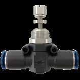
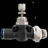
85955-041/4 .709(18).236(6)M12x1.571(14,5).598(15)1.476(37.5)÷1.712(43.5).709(18)2.046(52).551(14)
85955-05 5/16 (8) .787(20).256(6,5)M14x1.658(16,5).677(17)1.555(39.5)÷1,791(45.5).787(20)2.292(58).630(16)
85955-063/8 .928(23,5).315(8)M16x1.767(19,5).749(19)1.870(47.5)÷2.106(53.5).887(22,5)2.637(67).709(18)
9.32
Flow Control Valves
I E Ø 3,4 L F C H Dmax CH G E F C H A Ø 3,4 L1 L2 Dmax B CH CH G Part No. TubeA BCDEFGHIL1L2CHCH1 85950-53-02 5/32 (4) 1/8 .217(5,5).787(20).236(6)M12x1.658(16,5).598(15)1.555(39.5)÷1,791(45.5).709(18)1.134(29)1.016(26).551(14).630(16) 85950-04-021/41/8 .217(5,5).787(20).236(6)M12x1.658(16,5).598(15)1.555(39.5)÷1,791(45.5).709(18)1.134(29)1.016(26).551(14).630(16) 85950-04-041/41/4 .276(7).787(20).236(6)M12x1.658(16,5).598(15)1.555(39.5)÷1,791(45.5).709(18)1.134(29)1.016(26).551(14).630(16)
5/16 (8) 1/4
85950-05-04
.276(7).908(23).256(6,5)M14x1.658(16,5).677(17)1,673(42.5)÷1,909(48.5).787(20)1.319(33,5)1.134(29).630(16).787(20) 85950-05-06 5/16 (8) 3/8
85950-06-083/81/2 .355(9).976(25).315(8)M16x1.827(21).749(19)1,673(42.5)÷2,145(54.5).887(22,5)1.359(34,5)1.319(33,5).709(18).827(21) I E Ø 3,4 L F C H Dmax CH G I E Ø 3,4 L F C H Dmax CH G Part No. Tube CDEFGHILCH 85955-53 5/32 (4) .709(18).236(6)M12x1.571(14,5).598(15)1.476(37.5)÷1.712(43.5).709(18)2.046(52).551(14)
Page 152
85960
MALE “UNIVERSAL SHORT” - TUBE IN-LINE FLOW CONTROL (BIDIRECTIONAL FLOW)
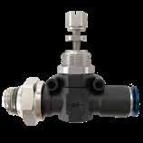
.217(5,5).787(20).236(6)M12x1.658(16,5).598(15)1.555(39.5)÷1,791(45.5).709(18)1.129(28,5)1.016(26).551(14).630(16)
85960-04-021/41/8 .217(5,5).787(20).236(6)M12x1.658(16,5).598(15)1.555(39.5)÷1,791(45.5).709(18)1.129(28,5)1.016(26).551(14).630(16)
85960-04-041/41/4 .276(7).787(20).236(6)M12x1.658(16,5).598(15)1.555(39.5)÷1,791(45.5).709(18)1.129(28,5)1.016(26).551(14).630(16)
85960-05-04 5/16 (8) 1/4 .276(7).908(23).256(6,5)M14x1.658(16,5).677(17)1,673(42.5)÷1,909(48.5).787(20)1.319(33,5)1.134(29).630(16).787(20)
85960-05-06 5/16 (8) 3/8 .295(7,5).908(23).256(6,5)M14x1.658(16,5).677(17)1,673(42.5)÷1,909(48.5).787(20)1.319(33,5)1.134(29).630(16).787(20)
85960-06-063/83/8 .295(7,5).968(24,5).315(8)M16x1.807(20,5).749(19)1,673(42.5)÷2,125(54).887(22,5)1.359(34,5)1.319(33,5).709(18).787(20)
85960-06-083/81/2 .355(9).976(25).315(8)M16x1.827(21).749(19)1,673(42.5)÷2,145(54.5).887(22,5)1.359(34,5)1.319(33,5).709(18).827(21)
9.33
Flow Control Valves
I E Ø 3,4 L F C H Dmax CH G CodeTubeA BCDEFGHIL1L2CHCH1
5/32 (4) 1/8
85960-53-02
L1 L2 F C H E Ø 3,4 A Dmax B CH CH1 G Page 153
TECHNICAL
Component Parts and Materials
1 Brass Adjusting Knob
2 Brass Nut
3 Brass Locking Nut
4 Brass Nipple
5 Anodized Aluminium Body
6 NBR O-Ring
7 Steel Spring
8 Seal floating washer
9 Brass Adjusting Needle
Component Parts and Materials
1 Brass Adjusting Knob
2 Brass Nut
3 Brass Locking Nut
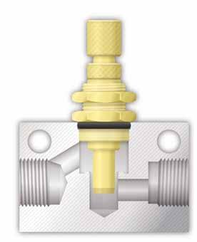
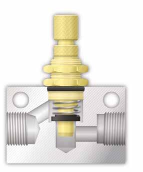
4 Brass Nipple
5 Anodized Aluminium Body
6 NBR O-Ring
7 Brass Adjusting Needle
9.34 Flow Control Valves 1907/2006 2011/65/CE PED 2014/68/UE SILICON FREE
CHARACTERISTICS Reference Standard FLOW REGULATORS Pressure Rating Vacuum ~ 250 PSI -0.99
20 bar -0.099 MPa ~ 2.0 MPa Bar Temperature Rating: NBR -4º F ~ 176º F -20º C ~ 80º C
bar ~
UNI-DIRECTIONAL BI-DIRECTIONAL 1 1 6 6 7 7 8 9 2 2 3 3 4 4 5 5 Page 154
82850
UNI-DIRECTIONAL INLINE VALVE
82860
BI-DIRECTIONAL INLINE NEEDLE VALVE
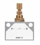
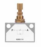
9.35 Flow Control Valves
D F A C L CH H M B 82850-1/4 Part No.A NPTF BCHDFLminLmaxMCH 82850-02 1/8 1.378(35).866(22).709(18).984(25).177(4,5)1.023(26)1.417(36)M12x0.75.590(15) 82850-041/4 1.811(46)1.181(30).787(20)1.378(35).256(6,5)1.023(26)1.417(36)M12x0.75.590(15) 82850-063/8 1.968(50)1.181(30).984(25)1.378(35).256(6,5)1.259(32)1.653(42)M18x1.5.866(22) 82850-081/2 2.362(60)1.575(40).984(25)1.732(44).256(6,5)1.259(32)1.734(44)M18x1.5.866(22) D F B H CH L A C M 82860-1/4 Part No.A NPTF BCHDFLminLmaxMCH 82860-02 1/8 1.378(35).866(22).709(18).984(25).177(4,5)1.023(26)1.417(36)M12x0.75.590(15) 82860-041/4 1.811(46)1.181(30).787(20)1.378(35).256(6,5)1.023(26)1.417(36)M12x0.75.590(15) 82860-063/8 1.968(50)1.181(30).984(25)1.378(35).256(6,5)1.259(32)1.653(42)M18x1.5.866(22) 82860-081/2 2.362(60)1.575(40).984(25)1.732(44).256(6,5)1.259(32)1.734(44)M18x1.5.866(22) Flow Characteristics of Inline Flow Control Valves Inlet Pressure 101 PSI UNI-DIRECTIONAL BI-DIRECTIONAL 20 ‘ 024681012141618 100 200 300 400 500 600 700 Number of Adjusting Knob Turns 1/2 3/8 1/4 1/8 M5 Air rate Q at 32º F and 14.7 PSI 02468101214161820 100 200 300 400 500 600 700 800 900 1000 1100 1200 Number of Adjusting Knob Turns 1/2 3/8 1/4 1/8 M5 Air rate Q at 32º F and 14.7 PSI Outlet Pressure: Atmospheric Pressure 14.7 PSI Page 155
According to the UNI standards ref. UNI- ISO 5598, this valve is considered: “Valve which immediately opens its outlet to exhaust, whenever the pressure of the air decreases at the inlet.”
When system pressure (P) is dropped, exhaust air in the cylinder (A) is discharged directly from the exhaust port (R).
This valve exhausts to atmosphere. DO NOT use toxic, corrosive or flammable media.
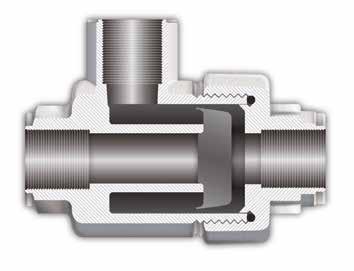
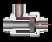
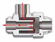
9.36 Flow Control Valves 1907/2006 2011/65/CE PED 2014/68/UE SILICON FREE TECHNICAL CHARACTERISTICS Reference Standard QUICK EXHAUST VALVES Pressure Rating 4.35 PSI ~ 145 PSI 0.3 bar ~ 10 bar 0.003 MPa ~ 1.0 MPa Bar Component Parts and Materials 1 Nickel Plated Brass Body 2 Nylon Cap Seal 3 Nickel Plated Brass Cap 4 NBR Piston Temperature Rating -4º F ~ 176º F -20º C ~ 80º C
Media • Compressed air WARNING!
Threads NPTF 82650 QUICK EXHAUST VALVE Part No.A NPTF M1M2CH 82650-021/8 1.653(42).768(19.5).591(15) 82650-041/4 2.125(54).984(25).748(19) 82650-063/8 2.381(60,5)1.043(26,5).866(22) 82650-081/2 2.834(72)1.260(32)1.024(26) 82650-123/4 3.664(88)1.457(37)1.260(32) 82650-161 4.291(109)1.890(48)1.811(46) CH M1 A M2 A A RP A A R R P P
System pressure is applied to the inlet port (P), flow is directed to cylinder port (A).
1 2 3 4 Page 156
TECHNICAL
This Slide Valve can be considered a reversing ON-OFF valve. When in the closed position, it allows the used air to exit to the atmosphere.
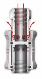
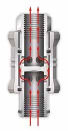
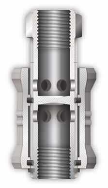
ON OFF
In the On position, the air coming from the air source passes through the holes on the stem of the valve.
In the OFF position, the air in the circuit passes through the holes on the stem and automatically exits to the atmosphere.
1
2
3
4
9.37
1907/2006 2011/65/CE PED 2014/68/UE SILICON FREE
Flow Control Valves
CHARACTERISTICS Reference Standard
Pressure Rating 4.35 PSI ~ 145 PSI 0.3 bar ~ 10 bar 0.003 MPa ~ 1.0 MPa Bar Component Parts and Materials
SLIDE VALVES
Aluminium Sleeve
Nickel Plated Brass Stem
NBR O-Ring
Steel
Temperature Rating -4º F ~ 176º F -20º C ~ 80º C
Compressed air
Shaft Clip
Media
NPTF 82660 SLIDE VALVE Part No.A NPTF BLCH 82660-021/8 .984(25)1.890(48).551(14) 82660-041/4 1.181(30)2.283(58).669(17) 82660-063/8 1.378(35)2.756(70).866(22) 82660-081/2 1.575(40)3.150(80)1.024(26) CH L B A A
Threads
1 2 3 4 Page 157
Check Valves allow air to flow in only one direction. They do not allow air flow the opposite direction.
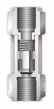
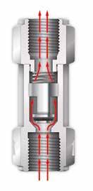
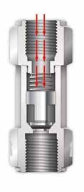
They operate directly with the air that passes through. Check Valves are normally used as safety device, permitting air pressure in a part of the circuit. The internal spring keeps the valve closed.
Component Parts and Materials
1 Nickel Plated Brass Body
2 NBR O-Ring
3 Steel Spring
4 Nickel Plated Brass Shutter
5 NBR O-Ring
6 Nickel Plated Brass Body
Media
Compressed air
Threads
9.38
1907/2006 2011/65/CE PED 2014/68/UE SILICON FREE
Flow Control Valves
29
0.2 MPa
0.8 MPa Approximate
Pressure 29 PSI 2 bar 0.02 MPa Bar
TECHNICAL CHARACTERISTICS Reference Standard UNIDIRECTIONAL VALVES OR NON RETURN VALVES Pressure Rating
PSI ~ 116 PSI 2 bar ~ 8 bar
~
Opening
NPTF
1 2 3 4 5 6 NBR -4º F ~ 176º F -20º C ~ 80º C
Rating FKM on request (only for 82662 -82663) 5º F ~ 392º F -15º C ~ 200° C Page 158
Temperatures
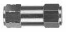
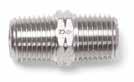
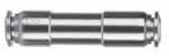
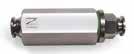
9.39
82662 FEMALE X FEMALE 82663 MALE X MALE 82664 INCH TUBE X TUBE 82670VM INLINE FILTER Part No.A NPTF LCH 82662-021/8 1.437(36,5).512(13) 82662-041/4 1.850(47).669(17) L CH A A Part No.A NPTF LESH 82663-041/4 1.220(31).551(14).512(13) 82663-063/8 1.220(31).748(19).512(13) A A H L ES Part No. Tube LB 82664VM-04-041/4 2.047(52).512(13) 82664VM-06-063/8 2.244(57).669(17) Part No. Tube LCH1CH2 82670VM-041/4 2.579(65,5).748(19).512(13) 82670VM-063/8 2.834(72).748(19).669(17) CH1 CH2 L IN Page 159
Flow Control Valves
9.40 Flow Control Valves Flow Rates of Exhaust Flow Rates of Exhaust with a drop of 14.5 PSI CHECK VALVES SPECIFICATIONS 3/8 - 1/2 1/4 1/8 M5 3/8 - 1/2 1/4 1/8 M5 0 18 5 35 10 53 21 70 31 88 42 106 53 123 63 141 74 159 84 176 95 194 105 211 116 230 127 153045607590105 0153045607590105 Inlet Pressure P1 (PSI) Inlet Pressure P1 (PSI) Air rate (CFM) Air rate (CFM) Page 160
BLOCK VALVES
TECHNICAL CHARACTERISTICS
Aignep Block Valves are pneumatic devices used to control the movement of the cylinder. They install directly on the inlet and outlet ports of the cylinder and lock the piston in case of a drop in air pressure. Block Valves are used as safety devices in case of emergency stops, the bursting of an air tube, or anything that would stop the flow of air to the cylinder. Block Valves also enable the cylinder to be stopped in intermediate positions whenever the application would require such a solution.
UNI-DIRECTIONAL 82880
Advantages
1 Aignep Block Valves are available in Uni-Directional and Bi-Directional versions.
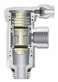
2 The bore of these valves do not reduce in size so airflow is never restricted.
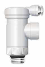
3 These valves are compact, and the threaded connection and tube connection can rotate for maximum versatility.
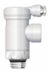
4 The threaded port can also recieve a flow control valve to adjust the speed of the cylinder.
BI-DIRECTIONAL 82890
Reference Standard
Component Parts and Materials
1 Nickel Plated Brass Cover Cap
2 Nylon Lip Seal
3 Brass Retaining Ring
4 Steel Spring
5 Brass Shutter Support
6 Brass Shutter
7 Nickel Plated Brass Base
8 NBR Lip Seal
9 Nickel Plated Collet
10 303 Stainless Steel Gripper

11 Nickel Plated Brass Sleeve
12 Technopolymer Safety Ring
13
Nickel Plated Brass Body
14 NBR Thread Seal
Media Compressed Air (lubricated and non lubircated)
9.41
Flow Control Valves
Pressure Rating 4.35 PSI ~ 145 PSI 0.3 bar ~ 10 bar 0.03 MPa ~ 1.0 MPa Temperature Rating -4º F ~ 176º F -20º C ~ 80º C Bar Size 1/8" 1/4" Orifice Ø Flow rate (87 PSI) 1/8" 1/4" 0 5.5 mm 0 8 mm 1/8" 1/4" 26.5 CFM 50.1 CFM 1907/2006 2011/65/CE PED 2014/68/UE SILICON FREE
1 9 10 11 12 13 14 8 2 3 4 5 6 7 Page 161
Pneumatic circuit - Cylinder in Action
The PO check circuit is connected to the cylinder circuit. When P1 pressure is applied to the directional control valve, pressure is applied simultaneously to PO check valve A and a pilot signal to PO check valve B. The cylinder will extend. When the directional control valve shifts, pressure is applied to PO check valve B with a pilot signal sent to PO check valve A. The cylinder will retract.
Pneumatic circuit - Cylinder at Rest
Remove P1 pressure from the directional control valve to lock the cylinder in place even under load conditions.
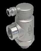
9.42
Control
82880 UNI-DIRECTIONAL CHECK VALVE A B L1 L2 Ø5/32 (Ø4) D L3 A1 Part No. A A1 NPTF BL1L2L3CHD 82880-02 1/8 1/8 .217(5,5)1.969(50).984(25).728(18,5).709(18).433(11) 82880-04 1/4 1/4 .276(7)1.988(50,5).984(25).807(20,5).709(18).433(11) Solenoid Valve Installation
Flow
Valves
OUT IN IN OUT OUTIN A B A B CLOSED CLOSED OUT OUT OUT Pilot Feeding OUT IN IN OUT OUTIN A B A B CLOSED CLOSED OUT OUT OUT
Page 162
Pneumatic circuit - Cylinder in Action
Note, the cylinder circuit and the pilot valve circuit are independent. With a pilot signal applied to the PO block valves and P1 pressure to the directional control valve the cylinder will extend and retract normally.
Pneumatic circuit - Cylinder at Rest
Remove the pilot signal pressure from the PO block valves to lock the cylinder in place even under load conditions.
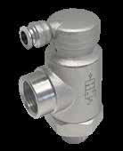
9.43
82890 BI-DIRECTIONAL BLOCK VALVE A B L1 L2 Ø5/32 (Ø4) D A1 L3 Part No. A A1 NPTF BL1L2L3CHD 82890-02 1/8 1/8 .217(5,5)1.969(50).984(25).728(18,5).709(18).433(11) 82890-04 1/4 1/4 .276(7)1.988(50,5).984(25).807(20,5).709(18).433(11)
Flow Control Valves
Installation
Pilot Feeding
SolenoidValvesPilot CLOSED CLOSED OUT OUT OUT OUT IN IN IN OUTIN IN IN OUT CLOSED CLOSED OUT OUT OUT OUT IN IN IN OUTIN IN IN OUT Page 163
Minimum pilot pressure is required to ensure proper valve function and is based on inlet pressure.
9.44
Pilot Pressure
Flow Control Valves
Z A Pilot Bar UNI-DIRECTIONAL 82880 1/8" - 1/4" 82880 - 82890 1/8" BI-DIRECTIONAL 82890 1/8" - 1/4" 82880 - 82890 1/4" Flow Rates Pilot Pressure (PSI) Inlet Pressure (PSI) A - Z Z - A 7.25 14.5 21.75 29 36.25 43.5 50.75 58 65.25 72.5 29 0 58 87 116145 Pilot Pressure (PSI) Inlet Pressure (PSI) A - Z Z - A 7.25 14.5 21.75 29 36.25 43.5 50.75 58 65.25 72.5 29 0 58 87 116145 Outlet Pressure (PSI) Outlet Pressure (PSI) 014.52943.55872.587101.5 014.52943.55872.587101.5 Flow Rate (CFM) Flow Rate (CFM) 7 14 21 28 35 42 7 14 21 28 35 42 49 56.5 63.5 70.5 77.5 85 92 29 PSI 43.5 PSI 58 PSI 72.5 PSI 87 PSI 29 PSI 43.5 PSI 58 PSI 72.5 PSI 87 PSI Inlet Pressure (PSI) Inlet Pressure (PSI) Pilot Pressure Inlet Pressure BLOCK
Page 164
VALVE SPECIFICATIONS
Ball Valves


reserves the right to vary models and dimensions without notice


Aignep
6310 Pg.10.7 86700 Pg.10.6 86710 Pg.10.7 86300 Pg.10.6 66300 Pg.10.10 86310 Pg.10.6 66310 Pg.10.10 86320 Pg.10.6 86330 Pg.10.6 6300 Pg.10.7 86720 Pg.10.7 86900 Pg.10.9 86910 Pg.10.9 6400 Pg.10.8 6410 Pg.10.8 6560 Pg.10.8 6570 Pg.10.8 86920 Pg.10.9 86915 Pg.10.9 66560 Pg.10.11 66570 Pg.10.11 Page 165
Stainless Steel Ball Valves
CHROME PLATED BRASS BALL VALVES Ball Valves
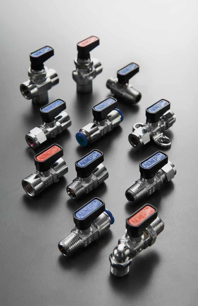
BALL VALVES Page 166
Media
Compressed air Water
• Oils
• Rated for gases, consult factory for details
PRESSURE - TEMPERATURE RATINGS DIAGRAM
Reference Standard

Component Parts and Materials
1 PA66 Glass Reinforced Handle

2 Chrome Nickel Plated Brass Spindle
3 NBR O-Ring Seal

4 PTFE Seats
5 Chrome Nickel Plated Brass Body
6 Acetalic Resin Plate
7 Steel Screw
8 NBR O-Ring Seal

9 Brass Fitting
10 Chrome Nickel Plated Brass Ball
Threads
Gas in conformity with ISO7.1, BS 21, DIN 2999.
Parallel gas in conformity with ISO 228 Class A.
10.3 Ball
+ FKM
NBR 1907/2006 2011/65/CE PED 2014/68/UE BS EN 331:2015 SILICON FREE Pressure Rating Vacuum ~ 250 PSI -0.99 bar ~ 20 bar -0.099 MPa ~ 2.0 MPa Bar NBR -4º F ~ 176º F -20º C ~ 80º C EPDM on request -40º F ~ 266º F -40º C ~ 130º C FKM on request 5º F ~ 266º C -15º C ~ 130º C
Valves PTFE
PTFE +
Temperatures
TECHNICAL CHARACTERISTICS
1 2 3 4 5 6 7 8 9 10 Page 167
10.4
BALL VALVES SPECIFICATIONS 30 50 40 60 80 70 2 10 20 0153045607590105 100 90 1/8" Inlet Pressure P1 (PSI) 30 PSI 45 PSI 60 PSI 75 PSI 90 PSI QN=64.42 CFM 30 50 40 60 80 70 2 10 20 0153045607590105 100 90 1/4" Inlet Pressure P1 (PSI) 30 PSI 45 PSI 60 PSI 75 PSI 90 PSI QN=58.32 CFM 60 100 80 120 160 140 2 20 40 0153045607590105 200 180 3/8" Inlet Pressure P1 (PSI) 30 PSI 45 PSI 60 PSI 75 PSI 90 PSI QN=126.62 CFM 210 320 265 370 475 425 50 105 160 0153045607590105 580 530 3/4" Inlet Pressure P1 (PSI) 30 PSI 45 PSI 60 PSI 75 PSI 90 PSI QN=410.29 CFM 120 180 150 210 270 240 30 60 90 0153045607590105 330 300 1/2" Inlet Pressure P1 (PSI) 30 PSI 45 PSI 60 PSI 75 PSI 90 PSI QN=201.63 CFM Outlet Pressure P2 (PSI) Outlet Pressure P2 (PSI) Outlet Pressure P2 (PSI) Outlet Pressure P2 (PSI) Outlet Pressure P2 (PSI) Flow Rate (CFM) Flow Rate (CFM) Flow Rate (CFM) Flow Rate (CFM) Flow Rate (CFM) Page 168
Ball Valves
Flow Rate & Pressure Drop
In the table below, we specify the flow rate factors of our ball valves. These factors represent the amount of air and water that flows through the valve. They are measured by Cubic Feet per Minute at 60° F.
Ball Valves 10.5
Factors of flow rate Thread Size CFM m3/h 1/8" 0.95 1.6 1/4" 0.86 1.4 3/8" 1.86 3.1 1/2" 2.97 5 3/4" 6.05 10.2 PARTSIZE NUMBER NBR FKM HNBR EPDM TYPEOFTHESEAL StandardShortHandlefor Valve1/8-1/4-3/8-1/2 StandardLongHandlefor Valve3/4 COLORTYPEOFHANDLE BluePlate LONGHandle LongHandlewith SpindleExtension 3/8-3/8 86300 NBR BLUE PLATE If required Option RedPlate GreenPlate WhitePlate YellowPlate GAS: EN331 MOP5 10 YellowPlateEN331 RO BL VE BN GI GI 0.1 0.20.30.40.50.60.80.9 1 10 0.7 0.03 0.045 0.06 0.075 0.09 0.105 0.12 0.135 0.3 0.45 0.6 0.75 0.9 1.05 1.2 1.35 3 4.5 6 7.5 9 10.5 12 13.5 15 1/4" 1/8" 1.5 0.15 0.015 3/8" 1/2" 3/4" == 2.03.04.05.06.07.08.09.0
Flow Rate (CFM) Pressure Drop (PSI) Page 169
BALL VALVES SPECIFICATIONS
86700 THREE POSITION (CLOSED CENTER)
Part No. A NPTF B NPTF DNESLCH
86300-02-021/81/8 .217(5,5).551(14)-.591(15)1.476(37,5).748(19).827(21)
86300-04-041/41/4 .217(5,5).551(14)-.591(15)1.811(46).748(19).827(21)
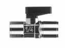
86300-06-063/83/8 .315(8).709(18)-.748(19)1.909(48,5).748(19).866(22)
86300-08-081/21/2 .394(10).866(22)-.906(23)2.441(62)1.024(26)1.201(30,5)
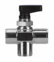
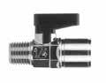
Part No. A NPTF B NPTF DNESFLCH
86310-02-021/81/8 .217(5,5).551(14)-.591(15).335(8,5)1.476(37,5).748(19).827(21) 86310-04-041/41/4 .217(5,5).551(14)-.591(15).512(13)1.811(46).748(19).827(21) 86310-06-063/83/8 .315(8).709(18)-.748(19).512(13)1.909(48,5).748(19).866(22)
10.6 Ball
X FEMALE
MALE
INCH
X
TUBE
INCH
Valves 86300 FEMALE
86310
X FEMALE 86320
TUBE
INCH
86330
TUBE X MALE
NPTF C L Es A B H
86310-12-123/43/4
NPTF C L Es F A B H Part No. TubeTube ESLCH 86320-02-021/81/8 .551(14)-.591(15)1.673(42,5).748(19).828(21) 86320-04-041/41/4 .551(14)-.591(15)1.831(46,5).748(19).828(21) 86320-06-063/83/8 .709(18)-.748(19)2.382(60,5).748(19).866(22) Inch tube C L Es H Part No. TubeA NPTF FNPTFESLCH 86330-53-02 5/32 (4) 1/8 .332(8.5).551(14)-.591(15)1.365(35).741(19).819(21) 86330-04-021/41/8 .332(8.5).551(14)-.591(15)1.574(40).741(19).819(21) 86330-04-041/41/4 .488(12.5).551(14)-.591(15)1.502(38.5).741(19).819(21) 86330-06-063/83/8 .507(13).709(18)-.748(19)1.755(45).741(19).858(22) Inch tube C L Es F A H Part No. A/B/C DNES1ES2LGH1H2Smax 86700-021/8 .217 (5,5) .669(17).669(17)1.476(37,5).748(19)1.319(33,5).650(16,5).177(4,5) 86700-041/4 .217 (5,5) .669(17).669(17)1.476(37,5).748(19)1.319(33,5).650(16,5).177(4,5) 86700-063/8 .276 (7) .669(17).827(21)1.909(48,5).748(19)1.378(35).866(22).177(4,5) NPTF NO GAS ES2 B G ES1 S A H1 H2 L C P Page 170
86310-08-081/21/2 .394(10).866(22)-.906(23).669(17)2.441(62)1.024(26)1.201(30,5)
.551(14)1.102(28)-1.181(30).689(17,5)2.500(63,5)1.953(49,5)1.319(33,5)
86710
THREE POSITION (OPEN CENTER)
NPTF
Part No. A/B/C DNES1ES2LGH1H2Smax
86710-021/8 .217(5,5).669(17).669(17)1.476(37,5).748(19)1.319(33,5).650(16,5).177(4,5)
86710-041/4 .217(5,5).669(17).669(17)1.476(37,5).748(19)1.319(33,5).650(16,5).177(4,5)
86710-063/8 .276(7).827(21).827(21)1.909(48,5).748(19)1.378(35).866(22).177(4,5)
NO GAS
86720 RIGHT ANGLE
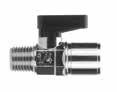
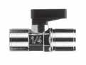
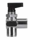
NPTF
Part No. A/B DNES1ES2LGH1H2Smax
86720-021/8 .217(5,5).669(17).669(17)1.476(37,5).748(19)1.319(33,5).650(16,5).177(4,5)
86720-041/4 .217(5,5).669(17).669(17)1.476(37,5).748(19)1.319(33,5).650(16,5).177(4,5) 86720-063/8 .276(7).669(17).827(21)1.535(39).748(19)1.378(35).866(22).177(4,5)
NO GAS
6300 FEMALE X FEMALE
6310
MALE X FEMALE
Part No. AB
DNESFMLGH 6300-1/81/81/8
Part No. AB DNESFMLGH 6310-1/8-1/81/81/8 .217(5,5).551(14)-.591(15).291(7,4).291(7,4)1.417(36).748(19).827(21) 6310-1/4-1/81/41/8 .217(5,5).551(14)-.591(15).433(11).291(7,4)1.594(40,5).748(19).827(21)
Ball Valves 10.7
ES2 B G ES1 S A H1 H2 L C P
ES2 B G ES1 S A H1 H2 L P
.217(5,5).551(14)-.591(15).291(7,4).291(7,4)1.417(36).748(19).827(21) 6300-1/41/41/4 .217(5,5).551(14)-.591(15).433(11).433(11)1.693(43).748(19).827(21) 6300-3/83/83/8 .315(8).709(18)-.748(19).449(11,4).449(11,4)1.850(47).748(19).866(22) 6300-1/21/21/2 .394(10).866(22)-.906(23).591(15).591(15)2.323(59)1.024(26)1.201(30,5) 6300-3/43/43/4 .551(14)1.102(28)-1.181(30).642(16,3).642(16,3)2.638(67)1.969(50)1.299(33)
BSPT
6310-1/4-1/41/41/4
6310-3/8-3/83/83/8
6310-1/2-1/21/21/2
6310-3/4-3/43/43/4
Page 171
.217(5,5).551(14)-.591(15).433(11).433(11)1.693(43).748(19).827(21)
.315(8).709(18)-.748(19).449(11,4).449(11,4)1.811(46).748(19).866(22)
.394(10).866(22)-.906(23).591(15).591(15)2.244(57)1.024(26)1.201(30,5)
.551(14)1.102(28)-1.181(30).642(16,3).642(16,3)2.480(63)1.969(50)1.299(33) BSPT
Part No. AB DNESFMLGH 6400-1/8-1/81/81/8 .217(5,5).551(14)-.591(15).276(7).276(7)1.378(35).748(19).827(21)
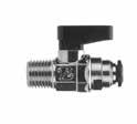
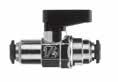
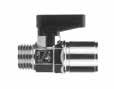
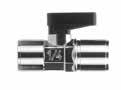
6400-1/4-1/41/41/4 .217(5,5).551(14)-.591(15).315(8).315(8)1.457(37).748(19).827(21)
6400-3/8-3/83/83/8 .315(8).709(18)-.748(19).354(9).354(9)1.654(42).748(19).866(22)
6400-1/2-1/21/21/2 .394(10).866(22)-.906(23).394(10).394(10)1.929(49)1.024(26)1.201(30,5) 6400-3/4-3/43/43/4 .551(14)1.102(28)-1.181(30).472(12).472(12)2.283(58)1.969(50)1.299(33)
10.8
Ball Valves 6400 FEMALE X FEMALE 6410 MALE X FEMALE 6560 TUBE X TUBE 6570 TUBE X MALE
BSPP Part No. AB DNESFMLGH 6410-1/8-1/81/81/8 .217(5,5).551(14)-.591(15).276(7).276(7)1.339(34).748(19).827(21) 6410-1/4-1/81/41/8 .217(5,5).551(14)-.591(15).315(8).276(7)1.378(35).748(19).827(21) 6410-1/4-1/41/41/4 .217(5,5).551(14)-.591(15).315(8).315(8)1.378(35).748(19).827(21) 6410-3/8-3/83/83/8 .315(8).709(18)-.748(19).354(9).354(9)1.535(39).748(19).866(22) 6410-1/2-1/21/21/2 .394(10).866(22)-.906(23).394(10).394(10)1.772(45)1.024(26)1.201(30,5) 6410-3/4-3/43/43/4 .551(14)1.102(28)-1.181(30).472(12).472(12)2.047(52)1.969(50)1.299(33) BSPP Part No. TubeTube DNESLGH 6560-4-4 5/32 (4)5/32 (4) .118(3).551(14)-.591(15)1.732(44).748(19).827(21) 6560-6-666 .197(5).551(14)-.591(15)1.890(48).748(19).827(21) 6560-8-8 5/16 (8)5/16 (8) .217(5,5).551(14)-.591(15)1.890(48).748(19).827(21) 6560-10-101010 .315(8).709(18)-.748(19)2.303(58,5).748(19).866(22) 6560-12-121212 .394(10).866(22)-.906(23)2.598(66)1.024(26)1.201(30,5) NO GAS Metric tube L Es H G Part No. ATube DNFESLCH 6570-4-1/81/8 5/32 (4) .118(3).335(8,5).551(14)-.591(15)1.378(35).748(19).827(21) 6570-6-1/81/86 .197(5).335(8,5).551(14)-.591(15)1.575(40).748(19).827(21) 6570-8-1/81/8 5/16 (8) .217(5,5).335(8,5).551(14)-.591(15)1.634(41,5).748(19).827(21) 6570-6-1/41/46 .315(8).492(12,5).551(14)-.591(15)1.516(38,5).748(19).827(21) 6570-8-1/41/48 .394(10).492(12,5).551(14)-.591(15)1.791(45,5).748(19).866(22) NO GAS Metric tube - BSPT C L ES F A H Page 172
BALL VALVE ACCESSORIES

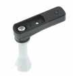


Ball Valves 10.9
86900 SHORT HANDLE 86910 LONG HANDLE 86915 STEM EXTENSION KIT 86920 COLOR PLATE Part No. CHSizeValve * 86900-02 .748(19).433(11)1/8-1/4-3/8 86900-08 1.024(26).590(15)1/2-3/4 * Standard Part No. CHSizeValve 86910-02 1.378(35).433(11)1/8-1/4-3/8 * 86910-08 1.968(50).590(15)1/2-3/4 * Standard Part No. SizeL 86915-02 1/82.283(58) 1/42.283(58) 3/82.323(59) 86915-08 1/22.677(68) 3/42.756(70) Part No. ColorSize 86920-01 Blue(StandardColor)1/8-1/4-3/8 86920-02 Red1/8-1/4-3/8 86920-03 Green1/8-1/4-3/8 86920-04 Yellow1/8-1/4-3/8 86920-05 White1/8-1/4-3/8 86921-01 Blue(StandardColor)1/2-3/4 86921-02 Red1/2-3/4 86921-03 Green1/2-3/4 86921-04 Yellow1/2-3/4 86921-05 White1/2-3/4 Page 173
GHINOX SERIES: BALLVALVE IN STAINLESS STEEL AISI 316 L
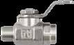
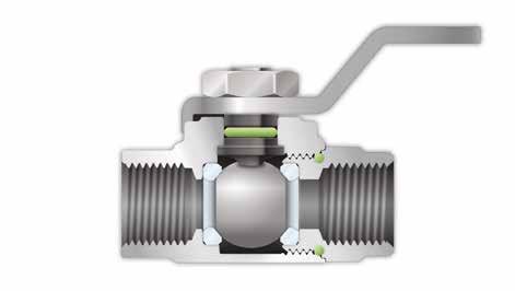
TECHNICAL CHARACTERISTICS
Component Parts and Materials
1 Stainless steel AISI 316L Body
2 PTFE Seats
3 Stainless steel AISI316L Spindle
4 FKM Seal O-RING
5 Stainless steel AISI316L Hex Nut
6 Stainless steel AISI316L Spindle
7 Stainless steel AISI316L Ball
8 FKM Seal O-RING
9 Stainless steel AISI316L Fitting
Threads
Gas in conformity with ISO7.1, BS 21, DIN 2999.
10.10 Ball Valves
Vacuum
580 PSI -0.99 bar ~ 40 bar -0.099 MPa ~ 4 MPa Bar
Pressure Rating
~
Media
Vacuum Water
• Compressed air
• Oils
Temperatures Minimum temperature 5 °F - 15 °C Maximum temperature in continuos 302 °F + 150 °C Maximum temperature for short term 356 °F + 180 °C 66300 FEMALE x FEMALE 66310 MALE x FEMALE Part No. AB DNCHFMLGH 66300-02-021/81/8 0.217(5,5)0.551-0.591(14-15)0.335(8,5)0.335(8,5)1.300(33)1.102(28)0.846(21,5) 66300-04-041/41/4 0.217(5,5)0.630-0.669(16-17)0.492(12,5)0.492(12,5)1.693(43)1.102(28)0.846(21,5) BSPP G H A L F M B CH Part No. A B BSPP DNCHFMLGH 66310-02-021/81/8 0.217(5,5)0.551-0.591(14-15)0.335(8,5)0.335(8,5)1.378(35)1.102(28)0.846(21,5) 66310-04-041/41/4 0.217(5,5)0.630-0.669(16-17)0.492(12,5)0.492(12,5)1.752(44,5)1.102(28)0.846(21,5) BSPT A F G H B M L CH 1 2 3 4 5 9 8 7 6 1907/2006 2011/65/CE PED 2014/68/UE SILICON FREE Reference Standard NSF/ANSI 169 Page 174
Ball Valves 10.11 66560 TUBE X TUBE 66570 TUBE X MALE CodeTubeTube DNCHLGH 66560-6-866 0.197(5)0.551-0.591(14-15)1.772(45)1.102(28)0.846(21,5) 66560-8-888 0.217(5,5)0.630-0.669(16-17)2.0048(52)1.102(28)0.846(21,5) Metric tube G H L CH BSPT CodeTubeA DNFCHLGH 66570-6-1/861/8 0.197(5)0.335(8,5)0.551-0.591(14-15)1.613(41)1.102(28)0.846(21,5) 66570-6-1/461/4 0.197(5)0.492(12,5)0.630-0.669(16-17)1.772(45)1.102(28)0.846(21,5) 66570-8-1/881/8 0.217(5,5)0.335(8,5)0.551-0.591(14-15)1.693(43)1.102(28)0.846(21,5) 66570-8-1/481/4 0.217(5,5)0.492(12,5)0.630-0.669(16-17)1.890(48)1.102(28)0.846(21,5) A F G H CH L Page 175
10.12 Ball Valves NOTES Page 176
Adapters

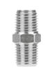
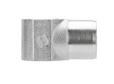

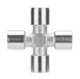

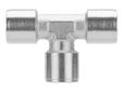

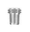


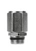
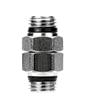


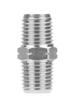


reserves the right to vary models and dimensions without notice


Aignep
Tubing NPTF Banjo Stem Assemblies N11 Pg.11.11 R811 Pg.11.14 81026 Pg.11.14 1750 Pg.11.14 82200N Pg.11.4 81410 Pg.11.7 82520N Pg.11.6 82201 Pg.11.4 81420 Pg.11.8 82203 Pg.11.4 81430 Pg.11.8 82241N Pg.11.5 51410 Pg.11.9 82242N Pg.11.5 51420 Pg.11.9 82280N Pg.11.5 51430 Pg.11.9 82400N Pg.11.6 82640N Pg.11.6 82300N Pg.11.5 82620N Pg.11.6 82510N Pg.11.6 82690 Pg.11.7 82205 Pg.11.4 PU - INCH Pg.11.12 PU - METRIC Pg.11.13 82320 Pg.11.5 Page 177
NICKEL-PLATED BRASS ADAPTERS
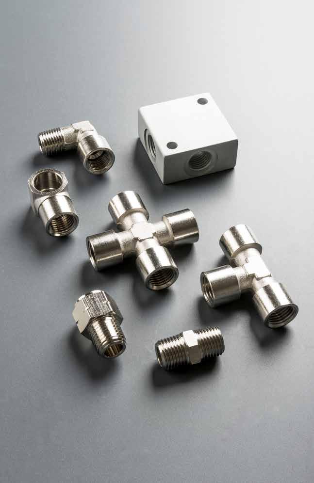
Adapters
ADAPTERS
TUBING Page 178
Reference Standard
TECHNICAL CHARACTERISTICS
Maximum temperature
Component Parts and Materials
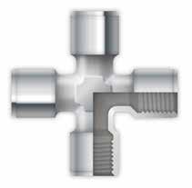
These fittings are made in OT UNI EN 12164/5 CW 614/7N and undergo a nickel-plating process. All other materials will be specified in catalog.
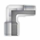
Vacuum ~ see data chart -0.99 bar ~ see data chart -0.099 MPa ~ see data chart
Connection Tubes
Tubes and general fittings.
Threads
Tapered gas in conformity with ISO7.1, BS 21, DIN 2999. Parallel gas in conformity with ISO 228 Class A.
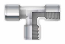
Metric in conformity with ISO R/262.
NPTF in conformity with ANSI B1.20.5
• Oils
Bar Page 179
11.3 Adapters 1907/2006 2011/65/CE PED 2014/68/UE SILICON FREE
1/8” 2175 PSI / 150 bar / 15 MPa 1/4” 1450 PSI / 100 bar / 10 MPa 3/8” 1080 PSI / 74 bar / 7.4 MPa 1/2” 725 PSI / 50 bar / 5 MPa Bar
SizeMaximumpressureadvised
Media
Compressed air Water
• General fluids for pneumatic, hydraulic and oildynamic facilities. 572 °F 300 °C
Pressure
Rating
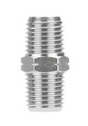
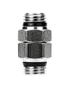
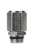
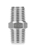
Adapters 11.4 82200N HEX NIPPLE 82201N NIPPLE - MALE X MALE 82203N NIPPLE - MALE X FEMALE 82205 NIPPLE TAPER Part No.A NPTF HLCH 82200N-021/8 .335(8,5).846(21,5).472(12) 82200N-041/4 .512(13)1.220(31).551(14) 82200N-063/8 .512(13)1.220(31).748(19) 82200N-081/2 .669(17)1.575(40).866(22) A A CH L H Part No.A NPTF BLCH1 82201N-04-041/4 .275(7)1.279(32,5).630(16) 82201N-06-063/8 .295(7,5)1.240(31,5).787(20) A L B B CH1 Part No.A NPTF B HLCH1CH2 82203N-04-041/41/4 .275(7)1.476(37,5).630(16).630(16) 82203N-06-063/83/8 .295(7,5)1.417(36).787(20).787(20) 82203N-06-043/81/4 .275(7)1.496(38).787(20).630(16) L B B A CH1 CH2 Part No.A BSPTB NPTF LCH 82205-1/8-1/81/81/8 .807(20,5).472(12) 82205-1/4-1/41/41/4 1.142(29).551(14) 82205-3/8-3/83/83/8 1.161(29,5).708(18) 82205-1/2-1/21/21/2 1.437(36,5).866(22) 82205-3/4-3/43/43/4 1.594(40,5)1.063(27) A B L CH Page 180
82241N
ADAPTER FEMALE G THREAD - MALE NPTF


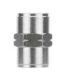


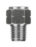
82242N
ADAPTER - FEMALE NPTF - MALE G THREAD
82280N
REDUCER FEMALE - MALE NPTF
82300N
COUPLING FEMALE NPTF
82320
COUPLING FEMALE NPTF
11.5
Adapters
Part No.A NPTFB BSPP HLCH 82241N-32-M5 10/32 UNF M5 .177(4,5).472(12).315(8) 82241N-02-021/81/8 .335(8,5).768(19,5).551(14) 82241N-04-041/41/4 .512(13)1.063(27).669(17) 82241N-06-063/83/8 .512(13)1.102(28).866(22) H L A B CH Part No.A BSPPB NPTF HLCH 82242N-021/81/8 .236(6).669(17).551(14) 82242N-041/41/4 .315(8).906(23).669(17) 82242N-063/83/8 .354(9).945(24).866(22) 82242N-081/21/2 .472(12)1.240(31,5)1.063(27) A H L B CH Part No. A NPTF B NPTF HLCH 82280N-02-321/8 10/32 UNF .335(8,5).571(14,5).472(12) 82280N-04-021/41/8 .512(13).748(19).551(14) 82280N-06-023/81/8 .512(13).768(19,5).748(19) 82280N-06-043/81/4 .512(13).906(23).748(19) 82280N-08-041/21/4 .669(17).965(24,5).866(22) 82280N-08-061/23/8 .669(17).571(14,5).472(12) CH B A L H Part No. A NPTF LCH 82300N-021/8 .748(19).551(14) 82300N-041/4 1.063(27).669(17) 82300N-063/8 1.063(27).866(22) 82300N-081/2 1.378(35)1.063(27) A CH L Part No. A BDLCH 82320-021/8 .217(5,5).394(10).315(8).197(5) 82320-041/4 .275(7).551(14).394(10).236(6) 82320-063/8 .295(7,5).669(17).433(11).315(8) 82320-081/2 .354(9).787(20).512(13).433(11) Page 181
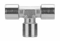
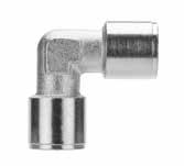
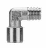
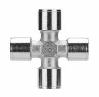

Adapters 11.6 82400N TEE FEMALE NPTF 82510N ELBOW - FEMALE NPTF 82520N ELBOW - FEMALE - MALE NPTF 82620N CROSS - FEMALE NPTF 82640N ALUMINUM DISTRIBUTION BLOCK - FEMALE Part No. A NPTF MCH 82400N-021/8 .669(19,5).472(12) 82400N-041/4 .906(26).512(13) 82400N-063/8 .945(28,5).630(16) 82400N-081/2 1.240(33,5).787(20) M CH A M A Part No. A NPTF MCH 82510N-021/8 .846(21,5).433(11) 82510N-041/4 1.083(27,5).512(13) 82510N-063/8 1.161(29,5).669(17) 82510N-081/2 1.339(34).787(20) M A CH M A Part No. A NPTF HM1M2CH 82520N-021/8 .335(8.5).827(21).748(19).433(11) 82520N-041/4 .512(13)1.083(27,5)1.004(25,5).512(13) 82520N-063/8 .512(13)1.161(29,5)1.083(27,5).669(17) 82520N-081/2 .669(17)1.339(34)1.260(32).787(20) M1 H A M2 A CH Part No. A NPTF MCH 82620N-021/8 .787(20).433(11) 82620N-041/4 1.063(27).512(13) 82620N-063/8 1.142(29).669(17) M A CH M A Part No. A NPTF LSFC 82640N-021/8 .984(25).630(16).177(4,5).169(4,5) 82640N-041/4 1.575(40).787(20).217(5,5).256(6,5) 82640N-063/8 1.969(50).984(25).217(5,5).295(7,5) 82640N-081/2 1.969(50)1.181(30).217(5,5).295(7,5) C F L A L C S Page 182
82690
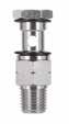
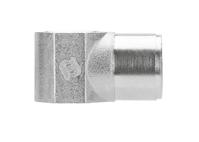
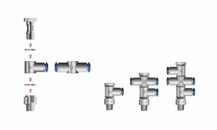
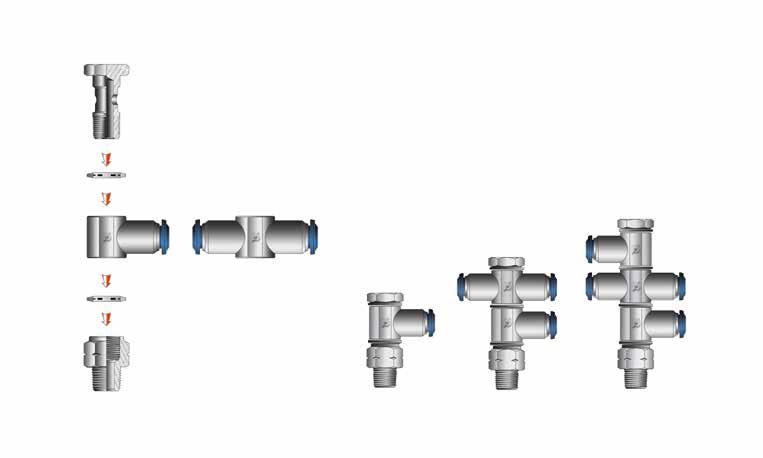
SINGLE
With nylon banjo body remove the washer.
Adapters 11.7
WASHER
WASHER
BANJO BODY FEMALE NYLON
NYLON
STEM ASSEMBLIES
NPTF BANJO
STEM Part No. A NPTF BLSCH 82690-3210/32 .240(6.1).570(14.5).484(12.3)N/A 82690-021/8 .394(10).649(16,5).590(15).551(14) 82690-041/4 .531(13,5).866(22).669(17).708(18) 82690-063/8 .688(17,5)1.043(26,5).787(20).827(21) B L A S Part No. A NPTF BCLCH 81410-3210/32 .177(4,5).492(15,5)1.200(30,5).315(8) 81410-021/8 .334(8,5).591(15)1.653(42).551(14) 81410-041/4 .511(13).669(17)2.047(52).669(17) 81410-063/8 .511(13).787(20)2.106(53,5).748(19) B L C CH A Page 183
81410 SINGLE BANJO
DOUBLE BANJO STEM 81430
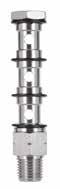
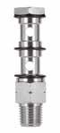
TRIPLE BANJO STEM
Examples of various banjo stems with single and double banjo bodies NYLON WASHER
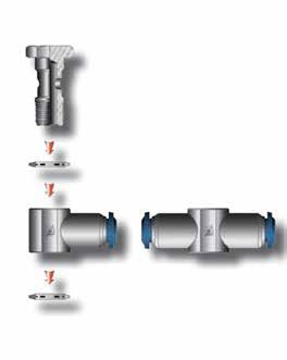
With nylon banjo body remove the washer.
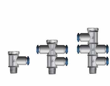
Adapters 11.8
81420
BANJO
NYLON WASHER BANJO STEM PartNo. 51410 51420 51430
BODY INCH OR METRIC
Single banjo stem Double banjo stem
Triple
banjo stem
ASSEMBLIES
BSPP BANJO STEM
Part No. A NPTF BCLCH 81420-021/8 .334(8,5).591(15)2.283(58).551(14) 81420-041/4 .511(13).669(17)2.755(70).669(17) 81420-063/8 .511(13).787(20)3.031(77).748(19) L B A C CH Part No. A NPTF BCLCH 81430-021/8 .334(8,5).591(15)2.913(74).551(14) 81430-041/4 .511(13).669(17)3.464(88).669(17) 81430-063/8 .511(13).787(20)3.897(99).748(19) A L B C CH Page 184
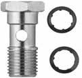
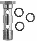
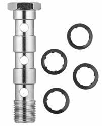
Adapters 11.9 51410 SINGLE BANJO STEM 51420 DOUBLE BANJO STEM 51430 TRIPLE BANJO STEM Part No.A BSPP BCLCH 51410-M5M5 .157(4).02(12.5).866(22).315(8) 51410-M6M6 .197(5).02(12.5).906(23).315(8) 51410-1/81/8 .236(6).591(15)1.102(28).551(14) 51410-1/41/4 .315(8).669(17)1.26(32).669(17) 51410-3/83/8 .354(9).787(20)1.417(36).748(19) 51410-1/21/2 .394(10).945(24)1.654(42).945(24) 51410-M12x1.5*M12X1.5 .315(8).669(17)1.26(32).669(17) ThisitemwillbesuppliedwiththePA66washers(ART.1610). *Withthisbanjostemusing1/4orientingbanjobody. A CB L CH Part No.A BSPP BCLCH 51420-1/81/8 .236(6).591(15).072(44,5).551(14) 51420-1/41/4 .315(8).669(17).082(50,5).669(17) 51420-3/83/8 .354(9).787(20)2.283(58).748(19) 51420-1/21/2 .394(10).945(24)2.677(68).945(24) 51420-M12x1.5*M12X1.5 .315(8).669(17).082(50,5).669(17) ThisitemwillbesuppliedwiththePA66washers(ART.1610). *Withthisbanjostemusing1/4orientingbanjobody. B A C L C CH Part No.A BSPP BCLCH 51430-1/81/8 .236(6).591(15)2.402(61).551(14) 51430-1/41/4 .315(8).669(17)2.717(69).669(17) 51430-3/83/8 .354(9).787(20)3.15(80).748(19) 51430-1/21/2 .394(10).945(24)3.701(94).945(24)
L BCC C A CH Page 185
ThisitemwillbesuppliedwiththePA66washers(ART.1610).
11.10 Adapters NOTES Page 186
PA TUBING
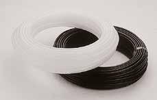
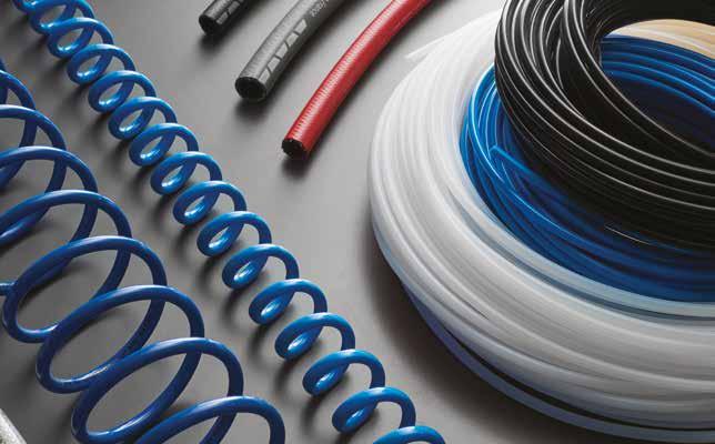
11.11
Tubing N11 PA 11 TUBING Part No. OD ID Wall Color Working Pressure 75°F Working Pressure 150°F Bend RadiusStandard Pack N11-021-100 1/8 .93.016Black225PSI123PSI.375100'Bag N11-022-1001/8 .93.016Natural225PSI123PSI.375100'Bag N11-531-100 5/32 (4) .108.016Black225PSI123PSI.375100'Bag N11-532-100 5/32 (4) .108.016Natural225PSI123PSI.375100'Bag N11-041-1001/4 .205.035Black225PSI123PSI.375100'Bag N11-042-1001/4 .205.016Natural225PSI123PSI.375100'Bag N11-051-100 5/16 (8) .232.016Black225PSI123PSI.375100'Bag N11-052-100 5/16 (8) .232.016Natural225PSI123PSI.375100'Bag N11-061-1003/8 .275.016Black225PSI123PSI.375100'Bag N11-062-1003/8 .275.016Natural225PSI123PSI.375100'Bag N11-081-1001/2 .375.016Black225PSI123PSI.375100'Bag N11-082-1001/2 .375.016Natural225PSI123PSI.375100'Bag Advantages 1 COUMPOUND: PA12 2 TEMPERATURE RANGE -60° / +200° 3 DIAMETER TOLERANCE -.004 / +.002 4 VACUUM RATING 5 HARDNESS 78 Rockwell R 6 COLOR: Black, Natural Page 187
Advantages
1 COUMPOUND: PU
2 TEMPERATURE RANGE -40° / -165°
3 DIAMETER TOLERANCE +/- .003 - .004

4 VACUUM RATING 125 psi - 200 psi
5 HARDNESS 98 Shore A
6 COLOR: Black, Natural, Red, Blue
Adapters 11.12
Part Number OD ID Wall Color Working Pressure at 68°F Best Pressure at 68°F Bend RadiusStandard Pack PU157-0-100 5/32” 3/32”0.32”Natural130psi400psi0.47”100'Bag PU157-1-1005/32” 3/32”0.32”Red130psi400psi0.47”100'Bag PU157-2-1005/32” 3/32”0.32”Black130psi400psi0.47”100'Bag PU157-3-1005/32” 3/32”0.32”Blue130psi400psi0.47”100'Bag PU340-0-1003/16” 1/8”0.32”Natural130psi330psi0.55”100'Bag PU340-1-1003/16” 1/8”0.32”Red130psi330psi0.55”100'Bag PU340-2-1003/16” 1/8”0.32”Black130psi330psi0.55”100'Bag PU340-3-1003/16”
PU445-0-1001/4” 5/32”0.45”Natural130psi370psi0.75”100'Bag PU445-1-1001/4” 5/32”0.45”Red130psi370psi0.75”100'Bag PU445-2-1001/4” 5/32”0.45”Black130psi370psi0.75”100'Bag PU445-3-1001/4” 5/32”0.45”Blue130psi370psi0.75”100'Bag PU562-0-1005/16” 3/16”0.62”Natural130psi330psi0.95”100'Bag PU562-1-1005/16” 3/16”0.62”Red130psi330psi0.95”100'Bag PU562-2-1005/16” 3/16”0.62”Black130psi330psi0.95”100'Bag PU562-3-1005/16” 3/16”0.62”Blue130psi330psi0.95”100'Bag PU662-0-1003/8” 1/4”0.62”Natural130psi330psi1.5”100'Bag PU662-1-1003/8” 1/4”0.62”Red130psi330psi1.5”100'Bag PU662-2-1003/8” 1/4”0.62”Black130psi330psi1.5”100'Bag PU662-3-1003/8” 1/4”0.62”Blue130psi330psi1.5”100'Bag PU890-0-1001/2” 3/8”0.62”Natural130psi330psi1.97”100'Bag PU890-1-1001/2” 3/8”0.62”Red130psi330psi1.97”100'Bag PU890-2-1001/2” 3/8”0.62”Black130psi330psi1.97”100'Bag PU890-3-1001/2” 3/8”0.62”Blue130psi330psi1.97”100'Bag
PU POLYURETHANE TUBING - INCH SIZES
1/8”0.32”Blue130psi330psi0.55”100'Bag
Page 188
Advantages
6
Adapters 11.13
Part Number OD ID Wall Color Working Pressure at 68°F Best Pressure at 68°F Bend RadiusStandard Pack PU4MM-0-100 4 mm 2.5mm0.75mmNatural174psi536psi20mm100'Bag PU4MM-1-100 4 mm 2.5mm0.75mmRed174psi536psi20mm100'Bag PU4MM-2-100 4 mm 2.5mm0.75mmBlack174psi536psi20mm100'Bag PU4MM-3-100 4 mm 2.5mm0.75mmBlue174psi536psi20mm100'Bag PU6MM-0-100 6 mm 4mm1mmNatural159psi464psi30mm100'Bag PU6MM-1-100 6 mm 4mm1mmRed159psi464psi30mm100'Bag PU6MM-2-100 6 mm 4mm1mmBlack159psi464psi30mm100'Bag PU6MM-3-100 6 mm 4mm1mmBlue159psi464psi30mm100'Bag PU8MM-0-100 8 mm 5.5mm1.25mmNatural145psi435psi45mm100'Bag PU8MM-1-100 8 mm 5.5mm1.25mmRed145psi435psi45mm100'Bag PU8MM-2-100 8 mm 5.5mm1.25mmBlack145psi435psi45mm100'Bag PU8MM-3-100 8 mm 5.5mm1.25mmBlue145psi435psi45mm100'Bag PU10MM-0-100 10 mm 7mm1.5mmNatural130psi406psi35mm100'Bag PU10MM-1-100 10 mm 7mm1.5mmRed130psi406psi35mm100'Bag PU10MM-2-100 10 mm 7mm1.5mmBlack130psi406psi35mm100'Bag PU10MM-3-100 10 mm 7mm1.5mmBlue130psi406psi35mm100'Bag PU12MM-0-100 12 mm 8mm2mmNatural159psi464psi30mm100'Bag PU12MM-1-100 12 mm 8mm2mmRed159psi464psi30mm100'Bag PU12MM-2-100 12 mm 8mm2mmBlack159psi464psi30mm100'Bag PU12MM-3-100 12 mm 8mm2mmBlue159psi464psi30mm100'Bag PU14MM-0-100 14 mm 10mm2mmNatural130psi391psi120mm100'Bag PU14MM-1-100 14 mm 10mm2mmRed130psi391psi120mm100'Bag
PU POLYURETHANE TUBING - METRIC SIZES
COUMPOUND: PU
TEMPERATURE RANGE -40° / -165°
DIAMETER TOLERANCE +/- .003 - .004
VACUUM RATING 125 psi - 200 psi
HARDNESS 98 Shore A
1
2
3
4
5
COLOR: Black, Natural, Red, Blue Page 189
R811
11.14
RECOIL ASSEMBLIES Part No. Fitting Male NPTF ID OD Lenght Straight Lenght Working Lenght Retracted Coil Diameter Working Pressure 75°F Working Pressure 150°F R811-043-012 1/4 1/4 .30912101/251/431/2185PSI100PSI R811-043-0251/4 1/4 .3092522101/231/2185PSI100PSI R811-043-0501/4 1/4 .30950442131/2185PSI100PSI R811-043-1001/4 1/4 .309100884231/2185PSI100PSI R811-053-0123/8 3/8 .4701210555/8185PSI100PSI R811-053-0253/8 3/8 .4702510101/455/8185PSI100PSI R811-053-0503/8 3/8 .4705010201/455/8185PSI100PSI R811-053-1003/8 3/8 .470100104155/8185PSI100PSI R811-083-0121/2 1/2 .625128.541/49185PSI100PSI R811-083-0251/2 1/2 .625251899185PSI100PSI R811-083-0501/2 1/2 .6255036189185PSI100PSI R811-083-1001/2 1/2 .62510072369185PSI100PSI T ubing 81026 RECOIL FITTING 1750 TUBE CUTTER Part No. A NPTF BCLCH 81026-041/4 .236(6).591(15)2.402(61).551(14) 81026-063/8 .315(8).669(17)2.717(69).669(17) 81026-081/2 .354(9).787(20)3.150(80).748(19) B A CH1 CH2 Part No. 1750 ACCESSORIES Page 190
reserves the right to vary models and dimensions without notice


Aignep
AC Mini p. 12.14 80111 Pg.12.14 80112 Pg.12.14 80211 Pg.12.14 80212 Pg.12.14 1/4 Multisocket - Stainless Steel p. 12.11 63190 Pg.12.12 63192 Pg.12.12 60191 Pg.12.11 60192 Pg.12.11 60221 Pg.12.11 60222 Pg.12.11 63262 Pg.12.12 63260 Pg.12.12 1/4 Multisocket p. 12.4 80223AC Pg.12.5 80221AC Pg.12.4 80222 Pg.12.5 80191 Pg.12.4 80192 Pg.12.4 80193 Pg.12.4 80221 Pg.12.4 80223 Pg.12.5 80222AC Pg.12.5 80271AC Pg.12.6 80272 Pg.12.6 80291 Pg.12.5 80292 Pg.12.5 80293 Pg.12.6 80271 Pg.12.6 80272AC Pg.12.6 3/8 Multisocket p. 12.8 80194 Pg.12.8 80273 Pg.12.6 80232AC Pg.12.9 80195 Pg.12.8 80231 Pg.12.8 80231AC Pg.12.8 80232 Pg.12.8 80298 Pg.12.9 Safety Couplers - Blow Guns p. 12.21 80221AC Pg.12.22 80222AC Pg.12.22 80621 Pg.12.21 80622 Pg.12.21 621 Pg.12.21 622 Pg.12.21 80225AC Pg.12.22 Industrial p. 12.16 80121 Pg.12.16 80122 Pg.12.16 80221 Pg.12.16 80222 Pg.12.16 80131 Pg.12.17 80132 Pg.12.17 80232 Pg.12.17 80231 Pg.12.17 8B121 8B122 Pg.12.22 361-362 Pg.12.24 Page 191
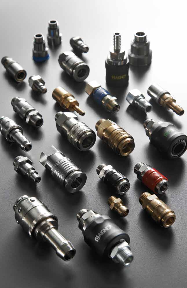
QUICK DISCONNECT COUPLERS Q Page 192
Quick Couplers
One socket for 3 different plugs
It’s a fact that there are various Quick-Disconnect plugs available on the market today. In most cases, each plug needs a specific of coupler that is not interchangeable.
To get around this issue, Aignep is proud to offer to its customers a practical and cost-effective solution.
MULTISOCKET is a universal coupler that works with the 3 main types of QD plugs.
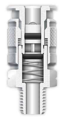
Component Parts and Materials
1 Nickel Plated Brass Body
2 420 Stainless Steel Ball
3 Nickel Plated Brass Guide Ring
4 NBR O-Ring Seal
5 302 Stainless Steel Ring Nut Spring
6 NBR O-Ring Seal
7 Nickel Plated Brass Sleeve
8 NBR O-Ring Seal
9 Nickel Plated Brass Shutter
10 302 Stainless Steel Shutter Spring
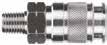


11 Nickel Plated Brass Coupler Media Compressed

12.3 1/4 Multisocket TRU-FLATE 5 mm 1/4 INDUSTRIAL 5.5 mm ARO 5.5 mm 1:1
1907/2006 2011/65/CE SILICON FREE PED 2014/68/UE
Standard
Reference
air
Aignep. Pressure Rating 0 ~ 232 PSI 0 bar ~ 16 bar 0 MPa ~ 1.6 MPa Maximum static pressure 507 PSI 35 bar 3.5 MPa Bar Threads NPTF Flow Rate CFM (NI/min) Plug87psi Δ14.5 87psi Δ7.2 87psi Δ0(ExhaustFree) 80220 38.8 (1100)28.25 (800)52.97 (1500) 80270 45.9 (1300)35.31 (1000)58.27 (1650) 80290 22.95 (650)16.95 (480)38.8 (1100) 1:1 1:1 Temperatures NBR -4º F ~ 176º F -20º C ~ 80º C FKM on request 14º F ~ 392º F -10º C ~ 200º C TECHNICAL CHARACTERISTICS 1 2 3 4 5 6 7 8 9 10 11 Page 193
For other fluids, consult the technical department
1/4”
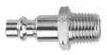
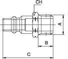

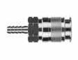
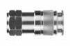

12.4 1/4 Multisocket 80191 1/4” MALE NPTF 80192 1/4” FEMALE NPTF 80193 1/4” BARB 80221 1/4” INDUSTRIAL MALE 80221AC 1/4” INDUSTRIAL MALE (STEEL)
Part No.A NPTF BCDCH 80191-041/4 .512(13)2.126(54).945(24).827(21) 80191-063/8 .512(13)2.126(54).945(24).827(21) 80191-081/2 .669(17)2.303(58,5).945(24).945(24) D A C CH B Part No.A NPTF BCDCH 80192-041/4 .533(13.5)2.126(54).945(24).827(21) 80192-063/8 .533(13.5)2.126(54).945(24).827(21) 80192-081/2 .689(17,5)2.323(59).945(24).945(24) D A B C CH Part No. A CDCH 80193-041/4 2.382(60,5).945(24).827(21) 80193-063/8 2.402(61).945(24).827(21) 80193-081/2 2.402(61).945(24).866(22) C CH D A+1mm
INDUSTRIAL Part No.A NPTF BCCH 80221-041/4 .512(13)1.634(41,5).669(17) 80221-063/8 .512(13)1.634(41,5).748(19) 80221-081/2 .669(17)1.811(46).866(22) Part No.A NPTF BCCH 80221AC-041/4 .512(13)1.634(41,5).669(17) 80221AC-063/8 .512(13)1.634(41,5).748(19) 80221AC-081/2 .669(17)1.811(46).866(22) HARDENED STEEL Page 194
MULTISOCKET
1/4"
80223

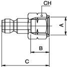

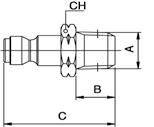
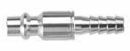

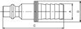
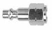


12.5 1/4 Multisocket
80222 1/4” INDUSTRIAL FEMALE
80222AC 1/4” INDUSTRIAL FEMALE (STEEL)
1/4” INDUSTRIAL
BARB
80223AC 1/4” INDUSTRIAL BARB (STEEL)
80291 1/4” TRU-FLATE MALE
No.A NPTF BCCH 80222-041/4 .531(13,5)1.535(39).669(17) 80222-063/8 .531(13,5)1.535(39).787(20) 80222-081/2 .689(17,5)1.693(43).944(24)
No.A NPTF BCCH 80222AC-041/4 .531(13,5)1.535(39).669(17) 80222AC-063/8 .531(13,5)1.535(39).866(22) 80222AC-081/2 .689(17,5)1.693(43).944(24) HARDENED STEEL Part No. A CD 80223-041/4 1.713(43,5).472(12) 80223-081/2 1.811(46).629(16) Part No. A CD 80223AC-041/4 1.713(43,5).472(12) HARDENED STEEL
FLATE Part No.A NPTF BCCH 80291-041/4 .512(13)1.457(37).669(17) 80291-063/8 .512(13)1.457(37).748(19) 80291-081/2 .669(17)1.634(41,5).866(22) Part No.A NPTF BCCH 80292-041/4 .531(13,5)1.358(34,5).669(17) 80292-063/8 .531(13,5)1.358(34,5).787(17) 80292-081/2 .689(17,5)1.516(38,5).945(24) Page 195
80292 1/4” TRU-FLATE FEMALE Part
Part
TRU
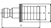
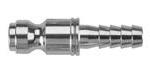

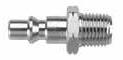

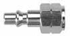
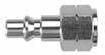
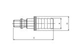
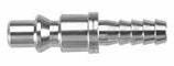
12.6 1/4 Multisocket 80293 1/4” TRU-FLATE BARB 80271 1/4” ARO MALE
1/4” ARO MALE (STEEL) 80272 1/4” ARO FEMALE
1/4” ARO FEMALE (STEEL)
1/4” ARO BARB Part No. A BD 80293-041/4 1.634(41,5).472(12) 80293-063/8 1.634(41,5).551(14) 80293-081/2 1.634(41,5).787(20) ARO Part No.A NPTF BCCH 80271-041/4 .511(13)1.574(40).669(17) 80271-063/8 .511(13)1.574(40).748(19) 80271-081/2 .669(17)1.771(45).866(22) Part No.A NPTF BCCH 80271AC-041/4 .511(13)1.574(40).669(17) HARDENED STEEL Part No.A NPTF BCCH 80272-041/4 .531(13,5)1.496(38).669(17) 80272-063/8 .531(13,5)1.496(38).787(20) 80272-081/2 .689(17,5)1.653(42).945(24) Part No.A NPTF CDCH 80272AC-041/4 .531(13,5)1.496(38).669(17) HARDENED STEEL Part No. A BD 80273-041/4 1.673(42,5).472(12) 80273-081/2 1.791(45,5).787(20) Page 196
80271AC
80272AC
80273
Reference Standard
TECHNICAL CHARACTERISTICS
One socket for 2 different plugs
It’s a fact that there are various Quick-Disconnect plugs available on the market today. In most cases, each plug needs a specific of coupler that is not interchangeable.

To get around this issue, Aignep is proud to offer to its customers a practical and cost-effective solution.
MULTISOCKET is a universal coupler that works with the 2 main types of QD plugs.
Component Parts and Materials
1 Nickel Plated Brass Body
2 420 Stainless Steel Ball
3 Nickel Plated Brass Guide Ring
4 NBR O-Ring Seal
5 302 Stainless Steel Ring Nut Spring
6 NBR O-Ring Seal
7 Nickel Plated Brass Sleeve
8 NBR O-Ring Seal
9 Nickel Plated Brass Shutter
10 302 Stainless Steel Shutter Spring
11 Nickel Plated Brass Coupler
Media
Compressed air
For other fluids, consult the technical department Aignep.
12.7 1/4 Multisocket
1:1
3/8 TRU-FLATE 9 mm 3/8 INDUSTRIAL 9 mm
1907/2006 2011/65/CE SILICON FREE PED 2014/68/UE
Pressure Rating 0 ~ 232 PSI 0 bar ~ 16 bar 0 MPa ~ 1.6 MPa Maximum static pressure 507 PSI 35 bar 3.5 MPa Bar Threads NPTF 1:1 Temperatures NBR -4º F ~ 176º F -20º C ~ 80º C FKM on request 14º F ~ 392º F -10º C ~ 200º C 1 2 3 4 5 6 7 8 9
Flow Rate CFM (NI/min) Plug87psi Δ14.5 87psi Δ7.2 87psi Δ0(ExhaustFree) 80230 88.2 (2500)72.3 (2050)116.5 (3300) 80297 88.2 (2500)72.3 (2050)116.5 (3300) 10 11 Page 197
3/8” MULTISOCKET
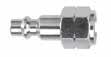

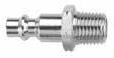
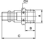


12.8 3/8 Multisocket 80194 3/8” MALE NPTF 80195 3/8” FEMALE NPTF 80231 3/8” INDUSTRIAL MALE 80231AC 3/8” INDUSTRIAL MALE (STEEL) 80232 3/8” INDUSTRIAL FEMALE
Part No.A NPTF BCDCH 80194-063/8 .512(13)2.342(59,5)1.102(28).945(24) 80194-081/2 .669(17)2.500(63,5)1.102(28).945(24) D A C CH B Part No.A NPTF BCDCH 80195-063/8 .531(13,5)2.362(60)1.102(28).945(24) 80195-081/2 .689(17,5)2.520(64)1.102(28).945(24) D A B C CH 3/8" INDUSTRIAL Part No.A NPTF BCCH 80231-063/8 .512(13)1.732(44).748(19) 80231-081/2 .669(17)1.909(48,5).866(22) Part No.A NPTF BCCH 80231AC-063/8 .512(13)1.732(44).748(19) 80231AC-081/2 .669(17)1.909(48,5).866(22) HARDENED STEEL Part No.A NPTF BCCH 80232-063/8 .531(13,5)1.634(41,5).787(20) 80232-081/2 .669(17)1.791(45,5).866(22) Page 198
80232AC
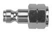

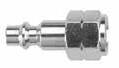

12.9
3/8” INDUSTRIAL FEMALE (STEEL) 80298 3/8” TRU-FLATE FEMALE Part No.A NPTF BCCH 80232AC-063/8 .531(13,5)1.634(41,5).787(20) 80232AC-081/2 .689(17,5)1.791(45,5).945(24) HARDENED STEEL 3/8" TRU FLATE Part No.A NPTF BCCH 80298-063/8 .531(13,5)1.654(42).787(20) 80298-081/2 .689(17,5)1.811(46).866(24) 3/8 Multisocket Page 199
Reference Standard
TECHNICAL CHARACTERISTICS
Bar
Pressure Rating
0 PSI ~ 232 PSI
0 bar ~ 16 bar
0 MPa ~ 1.6 MPa
Maximum static pressure
507 PSI 35 bar
3.5 MPa
Temperature Rating FKM
5º F ~ 392º F
C ~ 200º C
Media Compressed air Fluid for food and chemical industry compatible with all components.
Component Parts and Materials
1 316 Stainless Steel Body
2 420 Stainless Steel Ball
3 316 Stainless Steel Guide Ring
4 FKM O-Ring Seal
5 302 Stainless Steel Ring Nut Spring
6 FKM O-Ring Seal
7 316 Stainless Steel Sleeve
8 FKM O-Ring Seal
9 316 Stainless Steel Shutter
10 302 Stainless Steel Shutter Spring
11 316 Stainless Steel Coupler Threads
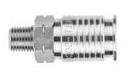


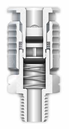
1/4
12.10
Multisocket -Stainless Steel
1907/2006 2011/65/CE PED 2014/68/UE SILICON FREE
-15º
NPTF BSPP 1 2 3 4 5 6 7 8 9 EUROPEAN 7.8 mm 1/4 INDUSTRIAL 5.5 mm ARO 5.5 mm 1:1 1:1 1:1 Flow Rate CFM (NI/min) Plug87psi Δ14.5 87psi Δ7.2 87psi Δ0(ExhaustFree) 1/4 INDUSTRIAL 88.2 (2500)72.3 (2050)116.5 (3300) EUROPEAN 53.32 (1510)42.38 (1200)79.45 (2250) 10 11 Page 200
1/4" MULTISOCKET STAINLESS STEEL
60191
1/4” MALE NPTF 316L (STAINLESS)
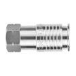
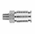
60192
1/4” FEMALE NPTF 316L (STAINLESS)
60221
1/4 INDUSTRIAL MALE 316L (STAINLESS)
60222
1/4 INDUSTRIAL FEMALE 316L (STAINLESS)
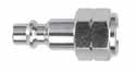

1/4 Multisocket -Stainless Steel 12.11
Part No.A NPTF BCDCH 60191-041/4 .511(13)2.086(53).945(24).827(21) D B C A CH Part No.A NPTF BCDCH 60192-041/4 .533(13,5)2.066(52,5).945(24).827(21) D C B A CH Part No.A NPTF BCCH 60221-041/4 .512(13)1.633(41).669(17) Part No.A NPTF BCCH 60222-041/4 .533(13,5)1.535(39).669(17) Page 201


1/4 Multisocket -Stainless Steel 12.12 63190 1/4” MALE 316L (STAINLESS) 63192 1/4” FEMALE 316L (STAINLESS) 63260 DN 7.8 MALE PLUG EUROPEAN PROFILE C A B CH 63262 DN 7.8 FEMALE PLUG EUROPEAN PROFILE C A B CH
Part No. A BCDCH 63190-041/4 .276(7)1.969(50).945(24).827(21) 63190-063/8 .295(7,5)1.988(50,5).945(24).827(21) 63190-081/2 .354(9)2.047(52).945(24).827(21) A C D B CH Part No.A BSPP BCDCH 63192-041/4 .433(11)2.028(51,5).945(24).827(21) 63192-063/8 .453(11,5)2.047(52).945(24).827(21) 63192-081/2 .591(15)2.224(56,5).945(24).945(24) D C B A CH Part No. A BCCH 63260-041/4 .276(7)1.319(33,5).669(17) 63260-063/8 .295(7,5)1.339(34).748(19) 63260-081/2 .354(9)1.417(36).945(24) Part No.A BSPP BCCH 63262-041/4 .433(11)1.299(33).669(17) 63262-063/8 .453(11,5)1.319(33,5).748(19) 63262-081/2 .591(15)1.457(37).945(24) Page 202
63 Series
Compressed air For other fluids, consult the technical department Aignep.
Component Parts and Materials
1 Nickel Plated Brass Body
2 420 Stainless Steel Ball
3 Nickel Plated Brass Sleeve
4 NBR O-Ring Seal
5 302 Stainless Steel Ring Nut Spring
6 Nickel Plated Brass Shutter
7 NBR O-Ring Seal
8 NBR O-Ring Seal
9 302 Stainless Steel Shutter Spring
10 Nickel Plated Brass Coupler
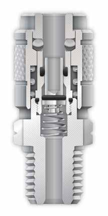
AC Mini 12.13 5 mm
CHARACTERISTICS 1907/2006 2011/65/CE PED 2014/68/UE SILICON FREE Reference Standard Flow Rate CFM (NI/min) 87psi Δ14.5 87psi Δ7.2 87psi Δ0(ExhaustFree) 8.48 (240) 6.71 (190) 11.3 (320) 1:1 Pressures 0 PSI ~ 232 PSI 0 bar ~ 16 bar 0 MPa ~ 1.6 MPa Maximum
507 PSI 35 bar 3.5 MPa Bar Media
Temperature Rating NBR -4º F ~ 176º F -20º C ~ 80º C FKM on request 14º F ~ 392º F -10º C ~ 200º C
TECHNICAL
static pressure
Threads NPTF 10 1 2 3 4 5 6 7 8 9 Page 203
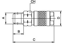
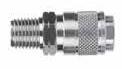
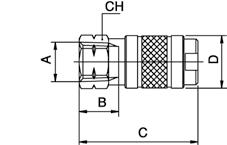
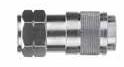
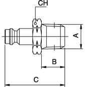
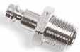
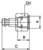
AC Mini 12.14 80111 AC MINI MALE 80112 AC MINI FEMALE 80211 AC MINI MALE PLUG 80212 AC MINI FEMALE PLUG Part No. A NPTF BCDCH 80111-021/8 .335(8,5)1.496(38).709(18).630(16) 80111-041/4 .512(13)1.673(42,5).709(18).630(16) 80111-063/8 .512(13)1.673(42,5).709(18).751(19) Part No. A NPTF BCDCH 80112-021/8 .335(8.5)1.457(37).709(18).630(16) 80112-041/4 .531(13,5)1.614(41).709(18).669(17) 80112-063/8 .531(13,5)1.614(41).709(18).787(20) Part No. A NPTF BCCH 80211-021/8 .335(8,5)1.122(28,5).551(14) 80211-041/4 .512(13)1.319(33,5).669(17) 80211-063/8 .512(13)1.319(33,5).748(19) Part No. A NPTF BCCH 80212-021/8 .374(9,5)1.063(27).551(14) 80212-041/4 .531(13,5)1.220(31).669(17) 80212-063/8 .531(13,5)1.220(31).787(20) Page 204
For other fluids, consult the technical department Aignep.
Component Parts and Materials
1 Nickel Plated Brass Body
2 Nickel Plated Brass Sleeve
3 420 Stainless Steel Ball
4 Nickel Plated Brass Guide Ring
5 NBR O-Ring Seal
6 302 Stainless Steel Ring Nut Spring
7 Nickel Plated Brass Shutter
8 NBR O-Ring Seal
9 NBR O-Ring Seal
10 302 Stainless Steel Shutter Spring
11 Nickel Plated Brass Coupler Threads
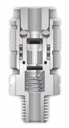
Industrial 12.15 5.5 mm 9 mm TECHNICAL CHARACTERISTICS 1907/2006 2011/65/CE PED 2014/68/UE SILICON FREE Reference Standard Pressure Rating 0 PSI ~ 232 PSI 0 bar ~ 16 bar 0 MPa ~ 1.6 MPa
pressure 507 PSI 35 bar
MPa Bar Media
air
Temperature Rating NBR -4º F ~ 176º F -20º C ~ 80º C FKM on request 14º F ~ 392º F -10º C ~ 200º C
Maximum static
3.5
Compressed
NPTF 1:1 1/4 INDUSTRIAL 3/8 INDUSTRIAL 1:1 Flow Rate CFM (NI/min) Plug87psi Δ14.5 87psi Δ7.2 87psi Δ0(ExhaustFree) 1/4 IND. 38.8 (1100)28.25 (800)52.97 (1500) 3/8 IND. 88.28 (2500)72.39 (2050)116.53 (3300) 1 2 3 4 5 6 7 8 9 10 11 Page 205
1/4” INDUSTRIAL


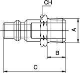
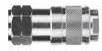
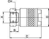

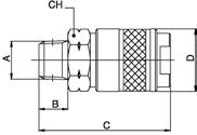
Industrial 12.16 80121 1/4” INDUSTRIAL MALE 80122 1/4” INDUSTRIAL FEMALE 80221 1/4” INDUSTRIAL MALE PLUG 80222 1/4” INDUSTRIAL FEMALE PLUG
INTERCHANGE Part No.A NPTF BCDCH 80121-041/4 .512(13)2.224(56,5).945(24).827(21) 80121-063/8 .512(13)2.224(56,5).945(24).827(21) 80121-081/2 .669(17)2.402(61).945(24).945(24) Part No.A NPTF BCDCH 80122-041/4 .531(13,5)2.205(56).945(24).827(21) 80122-063/8 .531(13,5)2.205(56).945(24).827(21) 80122-081/2 .689(17,5)2.421(61,5).945(24).945(24) Part No.A NPTF BCCH 80221-041/4 .512(13)1.634(41,5).669(17) 80221-063/8 .512(13)1.634(41,5).748(19) 80221-081/2 .669(17)1.811(46).866(22) Part No.A NPTF BCCH 80222-041/4 .531(13,5)1.535(39).669(17) 80222-063/8 .531(13,5)1.535(39).787(20) 80222-081/2 .689(17,5)1.693(43).944(24) Page 206
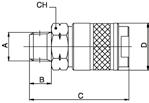
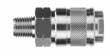
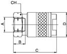
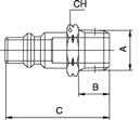
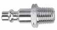
Industrial 12.17 80131 3/8” INDUSTRIAL MALE 80132 3/8” INDUSTRIAL FEMALE 80231 3/8” INDUSTRIAL MALE PLUG 80232 3/8” INDUSTRIAL FEMALE PLUG
Part No.A NPTF BCDCH 80131-063/8 .512(13)2.362(60)1.102(28).945(24) 80131-081/2 .669(17)2.4802(63)1.102(28).945(24) Part No.A NPTF BCDCH 80132-063/8 .531(13,5)2.343(59,5)1.102(28).945(24) 80132-081/2 .689(17,5)2.500(63,5)1.102(28).945(24) Part No.A NPTF BCCH 80231-063/8 .512(13)1.732(44).748(19) 80231-081/2 .669(17)1.909(48,5).866(22) Part No.A NPTF BCCH 80232-063/8 .531(13,5)1.634(41,5).787(20) 80232-081/2 .689(17,5)1.791(45,5).945(24) Page 207
3/8” INDUSTRIAL INTERCHANGE
12.18 1/4 Multisocket 1/4” Basic size: Industrial AIGNEP MILTONAMFLOAROCOILHOSEDIXONNAPAPARKERFOSTERTOMCO 80192-04 715C20-AUMSCF22-000150 DC2090-670 B23 2803 M184 80191-04 716 C21MSCM22-000152 DC2190-672 B22 2903 M181 80193-04 717C20-42MSCH22-000153DC204290-671B20-3B3603 M186 80193-06 717-6C20-44MSCH23-000 DC2044 3703 M187 80192-06 718C20-23MSCF23-000151DC202390-667B23E 3203 M185 80191-06 719C21-03MSCM23-000155DC210390-657B22E 3303 M182 80221-04 727 CP2123902-2101501DCP2190-674H2C 10-3 1804 80222-04 728 CP2023902-2001502DCP202190-676H3C 11-3 1805 80222-06 732CP20-2323902-3001505DCP202390-659H3C-E 15-3 1807 80221-06 733CP21-0323902-3101503DCP210390-677H2C-E 14-3 1806 80223-04 736CP21-4223902-2201506DCP214290-673H8C 16-3 1824 80223-06 736-6CP21-4423902-4201508DCP2144 H9C 17-3 1826 80192-04 745 UC2-16 80191-04 746 UC2-15 80192-04 755 C40BMSCF22-X00 DCB2090-615 B33 80191-04 756 C41BMSCM22-X00 DCB2190-617 B32 80193-04 1717-4C20-42LMSCP22-000 B20-3BP 80193-06 1717-6C20-44LMSCP23-000 B20-5BP 1/4” Basic size: ARO AIGNEP MILTONAMFLOAROCOILHOSEDIXONNAPAPARKERFOSTERTOMCO 80192-04 775C38,C46210 140 DC3890-613 B53210-3303A100 80191-04 776C37,C45210-212 DC37 B50210-3103A101 80193-04 776-4C38-42210-022 DC384290-679B50-3BP210-3603A104 80193-06 776-6C38-44210-215 DC3844 B50-5BP210-3703A105 80271-04 777 CP37 2608 1401DCP3790-618A2C210-10 200 80273-04 777-4CP37-423946 1406DCP3742 A8C210-16 400 80273-06 777-6CP37-4422238 DCP3744 210-17 500 80272-04 778 CP38 2609 1402DCP3890-620A3C210-11 300 1/4” Basic size: TRU-FLATE AIGNEP MILTONAMFLOAROCOILHOSEDIXONNAPAPARKERFOSTERTOMCO 80291-04 783 CP1TFPM22-0001601 DCP190-628 2C TF10 2154 80293-04 783-4CP1-42TFPH22-0001606DCP14290-630 8C TF16 2164 80293-06 783-6CP1-44TFPH23-0001608DCP14390-626 9C TF17 2166 80292-04 784 CP2TFPH22-0001602 DCP290-600 3C TF11 2155 80192-04 785 C2TFCF22-000160 DC290-610 B13TF3003A2184 80191-04 786 C1TFCM22-000162 DC190-607 B12TF3103A2181 80193-04 786-4C2-42TFCH22-000163 DC24290-611B10-3BTF3603A2186 80193-06 786-6C2-44TFCH23-000166 DC24490-609B10-5BTF3703A2188 80192-06 788 C2-23TFCF23-000 TF3203A2185 80191-06 789 C1-03TFCM23-000 DC103 TF3303A2182 3/8” Basic size: Industrial AIGNEP MILTONAMFLOAROCOILHOSEDIXONNAPAPARKERFOSTERTOMCO 80195-06 1835 C26MSCF33-000580 DC2690-680 25 4204 T420 80194-06 1836 C25MSCM33-000581 DC2590-682 24 4304 T430 80195-08 T440 80194-08 T450 80231-06 1837 CP2523903-3105801DCP2590-683H2E 42-4 T42 80232-06 1838 CP2623903-3005802DCP2690-681H3E 43-4 T43 80231-08 T44 80232-08 T45 3/8” Basic size: TRU-FLATE AIGNEP MILTONAMFLOAROCOILHOSEDIXONNAPAPARKERFOSTERTOMCO 80195-06 1805 C6TFCF33-000590 DC690-654 15 5005PT420 80194-06 1806 C5TFCM33-000591 DC590-656 14 5105PT430 80281-06 1807 CP5TFPM33-0005901 DCP590-658 2E TF42 PT42 80282-06 1808 CP6TFPF33-0005902 DCP690-660 3E TF43 PT43 Page 208
Safety Couplers

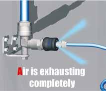

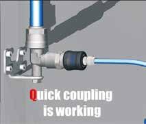

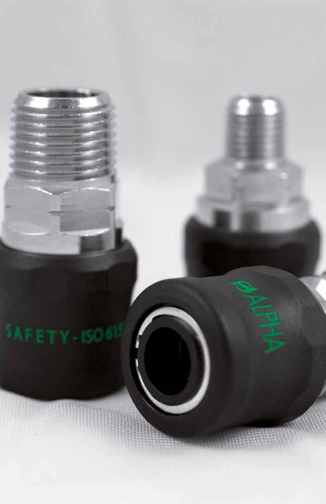
QUICK DISCONNECT SAFETY COUPLERS Page 209
Component Parts and Materials
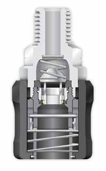
1 Nickel Plated Brass Coupler
2 Nickel Plated Brass Shutter
3 Nickel Plated Brass Ring
4 Nylon Trailing Pin Ring
5 Stainless Steel Restraining Ball Ring
6 Stainless Steel Spring
7 Stainless Steel Shaft
8 Stainless Steel Shutter
Safety Coupler 12.20 TECHNICAL CHARACTERISTICS 1907/2006 2011/65/CE PED 2014/68/UE SILICON FREE ISO 4414 Reference Standard 1 2 3 4 5 6 7 8 9 10 11 12 13 14
Rate CFM (NI/min) Part No. 87psi Δ14.5 87psi Δ7.2 87psi Δ0(ExhaustFree) 80220AC 33.55(950)24.72(700)49.44(1400) Pressure Rating Vacuum ~ 217 PSI -0.99 bar ~ 15 bar -0.099 MPa ~ 1.5 MPa Bar Media • Compressed air Temperature Rating -4º F ~ 176º F -20º C ~ 80º C
Flow
Clip
Spring
O-Ring
NBR O-Ring Seal
Stainless Steel Pin
Stainless Steel Ball
Nylon Body 14 Nylon Sleeve
gas in conformity with ISO 228 Class A Page 210
9 NBR
Seal 10
11
12
13
Threads Parallel
SAFETY COUPLERS


Safety Coupler 12.21 80621 MALE SAFETY COUPLER 80622 FEMALE SAFETY COUPLER 621 MALE SAFETY COUPLER 622 FEMALE SAFETY COUPLER Part No.A NPTF BCDCH 80621-041/4 .512(13)2.173(55)1.200(30,5).748(19) 80621-063/8 .512(13)2.173(55)1.200(30,5).748(19) 80621-081/2 .669(17)2.322(59)1.200(30,5).866(22) D CH A C B Part No.A NPTF BCDCH 80622-041/4 .531(13,5)2.165(55)1.200(30,5).669(17) 80622-063/8 .531(13,5)2.146(54,5)1.200(30,5).787(20) 80622-081/2 .689(17,5)2.323(59)1.200(30,5).945(24) D CH A C B Part No.A BSPP BCLCH 621-041/4 .512(13)2.173(55)1.200(30,5).748(19) 621-063/8 .512(13)2.173(55)1.200(30,5).787(20) 621-081/2 .512(13)2.173(55)1.200(30,5).984(25) CH A C B D
No.A BSPP BCLCH 622-041/4 .531(13,5)2.165(55)1.200(30,5).669(17) 622-063/8 .531(13,5)2.146(54,5)1.200(30,5).787(20) 622-081/2 .689(17,5)2.323(59)1.200(30,5).945(24) CH A B D C
Part
1:1 1/4 INDUSTRIAL 5.5 mm Page 211
80221AC
1/4
80222AC 1/4
80223AC 1/4”
8B121 SAFETY
8B122 SAFETY
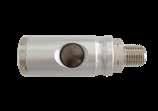
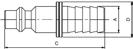
Safety Coupler 12.22
INDUSTRIAL
MALE (STEEL)
INDUSTRIAL
FEMALE (STEEL)
INDUSTRIAL
BARB (STEEL)
INDUSTRIAL
MALE SWIFTFIT
INDUSTRIAL
Part No.A NPTF BCCH 80221AC-041/4 .512(13)1.634(41,5).669(17) 80221AC-063/8 .512(13)1.634(41,5).748(19) 80221AC-081/2 .669(17)1.811(46).866(22) HARDENED STEEL Part No.A NPTF BCCH 80222AC-041/4 .531(13,5)1.535(39).669(17) 80222AC-063/8 .531(13,5)1.535(39).866(22) 80222AC-081/2 .689(17,5)1.693(43).944(24) HARDENED STEEL Part No. A CD 80223AC-041/4 1.713(43,5).472(12) HARDENED STEEL Part No.A NPTF BCDCH 8B121-04 1/4 - 18 .512(13)3.011(76,5).984(25).827(21) 8B121-06 3/8 - 18 .512(13)3.011(76,5).984(25).827(21) 8B121-08 1/2 - 14 .669(17)3.250(82,5).984(25).984(25) D A B C CH Part No.A NPTF BCDCH 8B122-04 1/4 - 18 .531(13,5)2.930(74.5).984(25).827(21) 8B122-06 3/8 - 18 .531(13,5)2.910(74).984(25).827(21) 8B122-08 1/2 - 14 .689(17,5)3.110(79).984(25).944(24) C D B A CH Page 212
FEMALE SWIFTFIT
BLOW GUNS
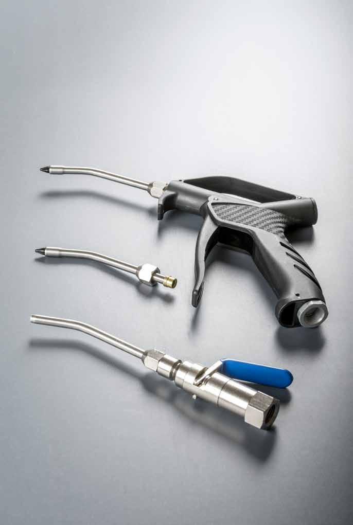
Safety Coupler 12.23 360
Series
Page 213
TECHNICAL CHARACTERISTICS
•
•
2
3 Nickel-plated Brass Locking Nut
4
BLOW GUN WITH STAINLESS STEEL PIPE
LAeq 89 dBA @ 6 bar (87 Psi)
LAeq 90 dBA @ 8 bar (116
BLOW GUN WITH STAINLESS STEEL PIPE
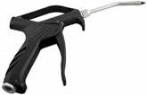
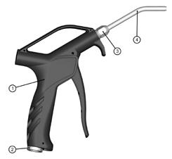
383 Nl/min @ 6 bar (87 Psi) - 500
LAeq 78 dBA @ 6 bar (87 Psi)
LAeq 84 dBA @ 8 bar (116 Psi)
12.24
Blow Guns 361
Code L L1B WB361 00 001 90 8.287(210,5)7.047(179) min max Temperature - 10 °C (14 F)+ 80 °C (176 F) Bar Pressure 12 bar (174 Psi) (1.2MPa) 433 Nl/min
Nl/min @ 8 bar (116 Psi)
@ 6 bar (87 Psi) - 533
Force on handle 19,8 N @ 6 bar (87 Psi) Blowing force 3,7 N @ 6 bar (87 Psi) 2003/10/CE Max 85 dBA 3 hr @ 6 bar (87 Psi) 3 hr @ 8 bar (116 Psi) OSHA 1910.95 (b) Max 90 dB 8 hr (116 Psi) L1 L B NPTF 1/4 0.866 (22)
Psi)
Media
Compressed Air
Water
Parts
Materials
Component
and
1 Technopolymer Body
Nickel-plated Brass Back Connection
Stainless Steel AISI 304 Nozzle 362
Code L L1B WB362 00 001 90 8.287(210,5)7.303(185,5) min max Temperature - 10 °C (14 F)+ 80 °C (176 F) Bar Pressure 12 bar (174 Psi) (1.2MPa)
bar
Nl/min @ 8
(116 Psi)
handle 19,8 N @ 6 bar
Blowing force 3,4 N @ 6 bar (87 Psi) 2003/10/CE Max 85 dBA 8 hr @ 6 bar (87 Psi) 6 hr @ 8 bar (116 Psi)
1910.95
Max 90 dB 8 hr OSHA 1910.242 (b) Max 2,1 bar (30 Psi) when blocked L1 L B NPTF 1/4 0.866 (22) Page 214
Force on
(87 Psi)
OSHA
(b)
Valves


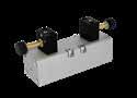
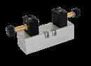
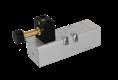


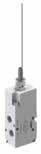


reserves the right to vary models and dimensions without notice
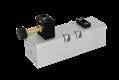

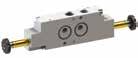


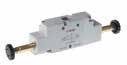


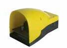


Aignep
07V Pg. 13.69 07V Pg. 13.71 Solenoid Valves Miniature Solenoid Valves 10 mm 07V Pg. 13.73 Miniature Solenoid Valves 15 mm 04V Pg. 13.56 05V Pg. 13.59 Micro Valves, Panel Mounted Individual and Manifold Base Mounted Valves 06V Pg. 13.67 Pedal Valves 01V Pg. 13.4 01V - X1V Pg. 13.10 01V Pg. 13.24 01V - X1V Pg. 13.30 Solenoid Pilot Valves Externally Piloted Solenoid Valves Air Pilot Valves Manual Valves 01V Pg. 13.40 01V Pg. 13.43 Mechanically Actuated Valves Din Rail Mounted, Fixed Length and Modular Manifold Bases 02V Pg. 13.49 03V Pg. 13.52 Micro Valves 16 mm Valves 08V Pg. 13.77 NAMUR Standard Valves Pg. 13.20 - Pg. 13.23 Solenoids and Connectors 10V Pg. 13.84 Valves ISO 5599 - Size 1 11V Pg. 13.88 Valves ISO 5599 - Size 2 Page 215
MANUAL, MECHANICAL, AIR PILOT AND SOLENOID PILOT VALVES
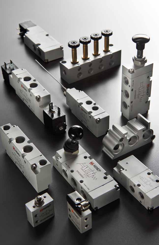
Valves
Page 216
VALVES
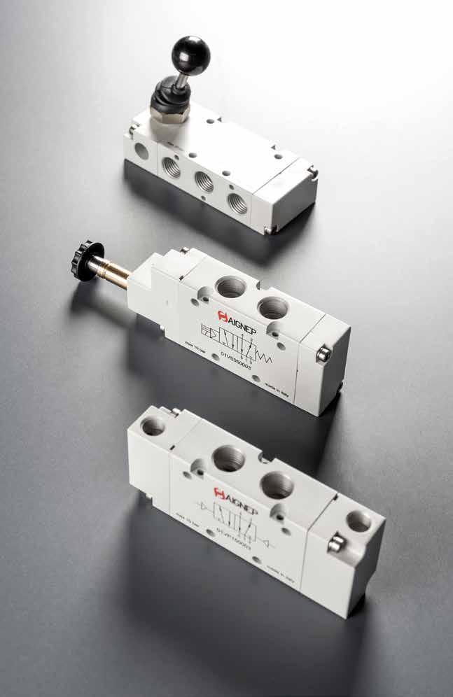
01V INLINE VALVES Page 217
SOLENOID PILOT VALVES
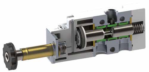
TECHNICAL CHARACTERISTICS
Parts and Materials
Anodised and painted aluminium body Chemical nickel-plated spool NBR seals
13.4 01V
Component
•
Reference Standard 1907/2006 2011/65/CE PED 2014/68/UE ATEX 2014/34/UE 1/81/43/81/2 THREADED G 1/8 NPTF 1/8 G 1/4 NPTF 1/4 G 3/8 NPTF 3/8 G 1/2 NPTF 1/2 6 bar FLOW RATE with ∆p 1 bar 740 NI/min 1200 NI/min 2000 NI/min 5000 NI/min Bar OPERATING PRESSURE Monostable 2 ÷ 10 bar 29 ÷ 145 psi Bistable 1 ÷ 10 bar 14.5 ÷ 145 psi TEMPERATURE min -10 °C 14 °F max +60 °C 140 °F V SOLENOID VOLTAGE 24V DC - 12V DC - 24V AC - 110V AC - 220V AC W MINIMUM POWER 2W - 3VA MANUAL CONTROL BISTABLE TORQUE OF TIGHTENING THE NUT SOLENOID 0.6 Nm Series 01V Reactuation 0 = Monostable spring return 1 = Bistable 0 Actuation S = Solenoid S Function 3 = 3/2 5 = 5/2 7 = 5/3 3 Thread = G N = NPTF NO = Normally open NC = Normally closed CC = All Ports Blocked OC = Cylinder Ports Open to Exhaust PC = Cylinder Ports Pressurized 00 = Function not privided NC 02 = 1/8 03 = 1/4 04 = 3/8 05 = 1/2 Size 02 Page 218
SINGLE SOLENOID PILOT - SPRING RETURN
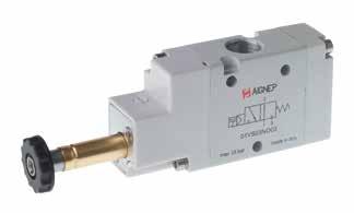
13.5 01V
3/2
G 1/8 - NPTF 1/8 Ø 34.2 72.8 4.2 Ø 3.1 1/8 15.5 90° 13 16.8 6.3 6.317.2 23 16.9 22 32 14.9 NPTF 3/8 30 19,9 39 3/8 Ø 3,1 90° 24,9 34,2 96 Ø 4,2 26 30 45 14 14 27 12,4 G 1/4 - NPTF 1/4 80.8 90° 19.4 34.2 Ø 4.2 Ø 3.1 1/4 8.422 1820.8 8.4 28 40 22 16.9 G 1/2 - NPTF 1/2 Ø 5.3 Ø 3.1 90° 15.6 15.6 44 40 60 30 24.9 44 41.6 1/2 34.2 144.8 37.6 Part No. Function Size Pack. 01V S0 3 NC 02 3/2 NC G 1/8 1 01V S0 3 NC 03 3/2 NC G 1/4 1 01V S0 3 NC 05 3/2 NC G 1/2 1 01V S0 3 NO 02 3/2 NO G 1/8 1 01V S0 3 NO 03 3/2 NO G 1/4 1 01V S0 3 NO 05 3/2 NO G 1/2 1 Part No. Function Size Pack. 01V S0 3 NC 02 N 3/2 NC NPTF 1/8 1 01V S0 3 NC 03 N 3/2 NC NPTF 1/4 1 01V S0 3 NC 04 N 3/2 NC NPTF 3/8 1 01V S0 3 NC 05 N 3/2 NC NPTF 1/2 1 01V S0 3 NO 02 N 3/2 NO NPTF 1/8 1 01V S0 3 NO 03 N 3/2 NO NPTF 1/4 1 01V S0 3 NO 04 N 3/2 NO NPTF 3/8 1 01V S0 3 NO 05 N 3/2 NO NPTF 1/2 1 22 31 31 NC NO Page 219
13.6 01V
DOUBLE SOLENOID PILOT G 1/8 - NPTF 1/8 94.8 90° 15.5 14.9 34.2 34.2 Ø 4.2 Ø 3.1 1/8 6.3 17.2 13 43 6.3 23 32 NPTF 3/8 39 37,1 24,9 30 Ø 3,1 90° 3/8 34,2 113,2 34,2 Ø 4,2 14 26 14 30 45 27 29,6 G 1/4 - NPTF 1/4 98 90° 19.4 42 34.2 34.2 Ø 4.2 Ø 3.1 1/4 8.4 22 18 8.4 28 40 16.9 22 G 1/2 - NPTF 1/2 162.4 90° 37.6 59.2 34.2 34.2 Ø 5.3 Ø 3.1 1/2 15.6 44 44 15.6 40 60 24.9 30 Part No. Function Size Pack. 01V S1 3 00 02 3/2 G 1/8 1 01V S1 3 00 03 3/2 G 1/4 1 01V S1 3 00 05 3/2 G 1/2 1 Part No. Function Size Pack. 01V S1 3 00 02 N 3/2 NPTF 1/8 1 01V S1 3 00 03 N 3/2 NPTF 1/4 1 01V S1 3 00 04 N 3/2 NPTF 3/8 1 01V S1 3 00 05 N 3/2 NPTF 1/2 1 Page 220
3/2
SINGLE SOLENOID PILOT - SPRING RETURN
13.7 01V
5/2
G 1/8 - NPTF 1/8 98 90° 31.8 13 34.2 1715 Ø 4.2 Ø 3.1 1/8 17.217.2 26 6.3 6.3 21 23 32 16.9 22 NPTF 3/8 30 32,5 32,5 19,9 24,9 3/8 3/8 Ø 3,1 90° 14 13 26 13 14 30 45 34,2 122 12,4 52 Ø 4,2 G 1/4 - NPTF 1/4 104 90° 45 36 34.2 22 20 Ø 4.2 Ø 3.1 1/4 22 22 9 18 9 25.4 28 40 16.9 22 G 1/2 - NPTF 1/2 189.2 90° 88 44 34.2 44 37.8 Ø 5.3 Ø 3.1 1/2 44 44 88 15.8 15.8 41.8 40 60 24.9 30 Part No. Function Size Pack. 01V S0 5 00 02 5/2 G 1/8 1 01V S0 5 00 03 5/2 G 1/4 1 01V S0 5 00 05 5/2 G 1/2 1 Part No. Function Size Pack. 01V S0 5 00 02 N 5/2 NPTF 1/8 1 01V S0 5 00 03 N 5/2 NPTF 1/4 1 01V S0 5 00 04 N 5/2 NPTF 3/8 1 01V S0 5 00 05 N 5/2 NPTF 1/2 1 Page 221
13.8 01V
DOUBLE SOLENOID PILOT G 1/8 - NPTF 1/8 112 90° 31.8 26 34.2 34.2 17 15 Ø 4.2 Ø 3.1 1/8 17.217.2 6.3 6.3 13 43 23 32 16.9 22 NPTF 3/8 30 32,5 32,5 71,3 24,9 3/8 3/8 Ø 3,1 90° 14 13 26 13 14 30 45 63,8 52 Ø 4,2 139,2 34,2 34,2 G 1/4 - NPTF 1/4 121.2 90° 36 42.6 34.2 34.2 45 22 Ø 5.3 Ø 3.11/4 22 22 9 9 20 18 28 40 16.9 22 G 1/2 - NPTF 1/2 88 206.8 90° 88 34.2 34.2 44 37.8 Ø 5.3 Ø 3.1 1/2 44 44 15.8 15.8 44 40 60 24.9 30 Part No. Function Size Pack. 01V S1 5 00 02 5/2 G 1/8 1 01V S1 5 00 03 5/2 G 1/4 1 01V S1 5 00 05 5/2 G 1/2 1 Part No. Function Size Pack. 01V S1 5 00 02 N 5/2 NPTF 1/8 1 01V S1 5 00 03 N 5/2 NPTF 1/4 1 01V S1 5 00 04 N 5/2 NPTF 1/2 1 01V S1 5 00 05 N 5/2 NPTF 1/2 1 Page 222
5/2
5/3
DOUBLE SOLENOID PILOT - SPRING CENTERED
13.9 01V
Part No. Function Size Pack. 01V S0 7 CC 02 5/3 CC G 1/8 1 01V S0 7 CC 03 5/3 CC G 1/4 1 01V S0 7 CC 05 5/3 CC G 1/2 1 01V S0 7 OC 02 5/3 OC G 1/8 1 01V S0 7 OC 03 5/3 OC G 1/4 1 01V S0 7 OC 05 5/3 OC G 1/2 1 01V S0 7 PC 02 5/3 PC G 1/8 1 01V S0 7 PC 03 5/3 PC G 1/4 1 01V S0 7 PC 05 5/3 PC G 1/2 1 G 1/8 - NPTF 1/8 112 90° 31.8 26 34.2 34.2 17 15 Ø 4.2 Ø 3.1 1/8 17.217.2 6.3 6.3 13 43 23 32 16.9 22 NPTF 3/8 30 32,5 32,5 71,3 24,9 3/8 3/8 Ø 3,1 90° 14 13 26 13 14 30 45 63,8 52 Ø 4,2 34,2 139,2 34,2 G 1/4 - NPTF 1/4 121.2 90° 36 42.6 34.2 34.2 45 22 Ø 5.3 Ø 3.11/4 22 22 9 9 20 18 28 40 16.9 22 G 1/2 - NPTF 1/2 88 206.8 90° 88 34.2 34.2 44 37.8 Ø 5.3 Ø 3.1 1/2 44 44 15.8 15.8 44 40 60 24.9 30 CC OC PC Part No. Function Size Pack. 01V S0 7 CC 02 N 5/3 CC NPTF 1/8 1 01V S0 7 CC 03 N 5/3 CC NPTF 1/4 1 01V S0 7 CC 04 N 5/3 CC NPTF 3/8 1 01V S0 7 CC 05 N 5/3 CC NPTF 1/2 1 01V S0 7 OC 02 N 5/3 OC NPTF 1/8 1 01V S0 7 OC 03 N 5/3 OC NPTF 1/4 1 01V S0 7 OC 04 N 5/3 OC NPTF 3/8 1 01V S0 7 OC 05 N 5/3 OC NPTF 1/2 1 01V S0 7 PC 02 N 5/3 PC NPTF 1/8 1 01V S0 7 PC 03 N 5/3 PC NPTF 1/4 1 01V S0 7 PC 04 N 5/3 PC NPTF 3/8 1 01V S0 7 PC 05 N 5/3 PC NPTF 1/2 1 Page 223
TECHNICAL CHARACTERISTICS
EXTERNALLY PILOTED SOLENOID VALVES
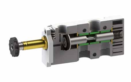
13.10 01V
1/81/4 THREADED G 1/8 NPTF 1/8 G 1/4 NPTF 1/4 6 bar FLOW RATE with ∆p 1 bar 740 NI/min1200 NI/min Bar OPERATING PRESSURE Vacuum ÷ 10 bar Vacuum ÷ 145 psi Bar PRESSURE DRIVE Monostable 2 ÷ 10 bar 29 ÷ 145 psi Bistable 1 ÷ 10 bar 14.5 ÷ 145 psi TEMPERATURE min -10 °C 14 °F max +60 °C 140 °F V SOLENOID VOLTAGE 24V DC - 12V DC - 24V AC 110V AC - 220V AC W MINIMUM POWER 2W - 3VA MANUAL CONTROL BISTABLE TORQUE OF TIGHTENING THE NUT SOLENOID 0.6 Nm
NBR seals Reference Standard 1907/2006 2011/65/CE PED 2014/68/UE ATEX 2014/34/UE Series 01V Reactuation 0 = Monostable spring return 1 = Bistable 0 Actuation A = Solenoid Assisted A 3 = 3/2 5 = 5/2 7 = 5/3 3 NO = Normally open NC = Normally closed CC = All Ports Blocked OC = Cylinder Ports Open to Exhaust PC = Cylinder Ports Pressurized 00 = Function not privided Function NC 02 = 1/8 03 = 1/4 Size 02 Thread = G N = NPTF Page 224
Component Parts and Materials • Anodised and painted aluminium body Chemical nickel-plated spool
3/2
SINGLE SOLENOID EXTERNAL PILOT - SPRING RETURN
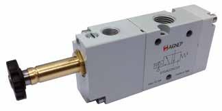
13.11 01V
G 1/8 - NPTF 1/8 90° 6,36,3 17,2 23 32 Ø4,2 15,5 74,3 36,2 14,9 1/8 13 16,8 16,9 22 Ø3,1 M5 (metric) 10/32 UNF (NPTF) 74,7 G 1/4 - NPTF 1/4 1/81/4 Ø3,1 16,9 22 18 20,8 67,1 90° 28 40 36,285,2 Ø4,2 19,4 22 228, 48,4 Part No. Function Size Pack. 01V A0 3 NC 02 3/2 NC G 1/8 1 01V A0 3 NC 03 3/2 NC G 1/4 1 01V A0 3 NO 02 3/2 NO G 1/8 1 01V A0 3 NO 03 3/2 NO G 1/4 1 Part No. Function Size Pack. 01V A0 3 NC 02 N 3/2 NC NPTF 1/8 1 01V A0 3 NC 03 N 3/2 NC NPTF 1/4 1 01V A0 3 NO 02 N 3/2 NO NPTF 1/8 1 01V A0 3 NO 03 N 3/2 NO NPTF 1/4 1 NC NO Page 225
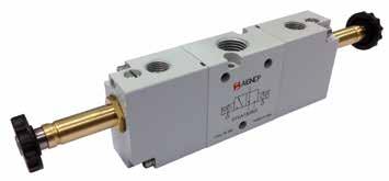
13.12 01V 3/2 DOUBLE SOLENOID EXTERNAL PILOT G 1/8 - NPTF 1/8 6,3 6,3 17,2 23 32 Ø4,2 36,2 14,9 1/8 M5 (metric) 10/32 UNF (NPTF) 13 16,9 22 Ø3,1 15,5 90° 97,80 36,20 40,30 81,00 G 1/4 - NPTF 1/4 106,80 42,40 88,70 1/8 1/4 Ø3,1 16,9 22 18 28 40 36,2 Ø4,2 19,4 22 228,4 8,4 36.2 90° Part No. Function Size Pack. 01V A1 3 00 02 3/2 G 1/8 1 01V A1 3 00 03 3/2 G 1/4 1 Part No. Function Size Pack. 01V A1 3 00 02 N 3/2 NPTF 1/8 1 01V A1 3 00 03 N 3/2 NPTF 1/4 1 Page 226
SINGLE SOLENOID EXTERNAL PILOT - SPRING RETURN
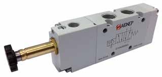
13.13 01V
5/2
G 1/8 - NPTF 1/8 90° 6,3 17,2 23 91,5 36,2 17,2 6,3 1715 31,8 32 Ø4,2 1/8 16,9 21 Ø3,1 13 21 26 74,7 M5 (metric) 10/32 UNF (NPTF) G 1/4 - NPTF 1/4 90° 922229 28 40 2220 45 Ø 4,2 108,4 36,2 1/4 1/8 Ø 3,1 16,9 22 32,4 18 36 Part No. Function Size Pack. 01V A0 5 00 02 5/2 G 1/8 1 01V A0 5 00 03 5/2 G 1/4 1 Part No. Function Size Pack. 01V A0 5 00 02 N 5/2 NPTF 1/8 1 01V A0 5 00 03 N 5/2 NPTF 1/4 1 Page 227
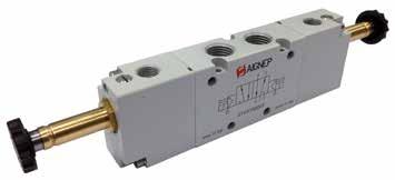
13.14 01V 5/2 DOUBLE SOLENOID EXTERNAL PILOT G 1/8 - NPTF 1/8 98,20 115 M5 (metric) 10/32 UNF (NPTF) 44,50 6,3 17,2 23 31 Ø4,2 36,2 17,2 6,3 17 15 31,8 1/8 16.9 21 Ø3,1 13 26 36.2 90° G 1/4 - NPTF 1/4 130 111,90 47 922229 28 40 2220 45 Ø 4,2 36,2 1/4 1/8 Ø3,1 16,9 22 18 36 36.2 90° Part No. Function Size Pack. 01V A1 5 00 02 5/2 G 1/8 1 01V A1 5 00 03 5/2 G 1/4 1 Part No. Function Size Pack. 01V A1 5 00 02 N 5/2 NPTF 1/8 1 01V A1 5 00 03 N 5/2 NPTF 1/4 1 Page 228
5/3
DOUBLE SOLENOID EXTERNAL PILOT - SPRING CENTERED
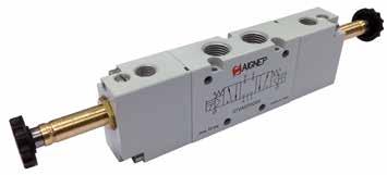
13.15 01V
G 1/8 - NPTF 1/8 98,20 115 M5 (metric) 10/32 UNF (NPTF) 44,50 6,3 17,2 23 31 Ø4,2 36,2 17,2 6,3 17 15 31,8 1/8 16.9 21 Ø3,1 13 26 36.2 90° G 1/4 - NPTF 1/4 130 111,90 47 922229 28 40 2220 45 Ø 4,2 36,2 1/4 1/8 Ø3,1 16,9 22 18 36 36.2 90° Part No. Function Size Pack. 01V A0 7 CC 02 5/3 CC G 1/8 1 01V A0 7 CC 03 5/3 CC G 1/4 1 01V A0 7 OC 02 5/3 OC G 1/8 1 01V A0 7 OC 03 5/3 OC G 1/4 1 01V A0 7 PC 02 5/3 PC G 1/8 1 01V A0 7 PC 03 5/3 PC G 1/4 1 Part No. Function Size Pack. 01V A0 7 CC 02 N 5/3 CC NPTF 1/8 1 01V A0 7 CC 03 N 5/3 CC NPTF 1/4 1 01V A0 7 OC 02 N 5/3 OC NPTF 1/8 1 01V A0 7 OC 03 N 5/3 OC NPTF 1/4 1 01V A0 7 PC 02 N 5/3 PC NPTF 1/8 1 01V A0 7 PC 03 N 5/3 PC NPTF 1/4 1 CC OC PC Page 229
EXTERNALLY PILOTED SOLENOID VALVES

13.16 X1V
1/41/2 THREADED G 1/4 NPTF 1/4 G 1/2 NPTF 1/2 6 bar FLOW RATE with ∆p 1 bar 1250 NI/ min 3000 NI/min TEMPERATURE min -50 °C -58 °F max +50 °C 122 °F V SOLENOID VOLTAGE 24V DC - 12V DC - 24V AC 110V AC - 220V AC W MINIMUM POWER 3W - 5VA MANUAL CONTROL BISTABLE TORQUE OF TIGHTENING THE NUT SOLENOID 0.6 Nm TECHNICAL CHARACTERISTICS Component Parts and Materials • Stainless Steel 316 L (1.4404) body Stainless Steel 316 L (1.4404) spool PUR seals and FKM O-Ring Reference Standard 1907/2006 2011/65/CE PED 2014/68/UE Series X1V Reactuation 0 = Monostable spring return 1 = Bistable 4 = Monostable pneumatic return 0 Actuation S = Solenoid S 3 = 3/2 5 = 5/2 3 NC = Normally closed 00 = Function not privided Function NC 02 = 1/8 03 = 1/4 Size 03 Thread = G N = NPTF Ways AISI 316L Page 230
3/2 Vie - Ways - Wege - Voies - Vías - Vias
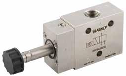
13.17 X1V
MONOSTABLE PNEUMATIC RETURN 2 31 NC X1V S4 3 NC 03 X1V S4 3 NC 05 Part No. Function Working pressure Size Pack. X1V S4 3 NC 03 3/2 NC 2÷10 bar 1/4 1 X1V S4 3 NC 05 3/2 NC 1÷10 bar 1/2 1 Page 231
5/2 Vie - Ways - Wege - Voies - Vías - Vias
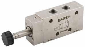
13.18 X1V
X1V S4 5 00 03 X1V S4 5 00 05 Part No. Function Working pressure Size Pack. X1V S4 5 00 03 5/2 2÷10 bar 1/4 1 X1V S4 5 00 05 5/2 2÷10 bar 1/2 1 Page 232
MONOSTABLE PNEUMATIC RETURN
5/2 Vie - Ways - Wege - Voies - Vías - Vias
TWO STABLE POSITIONS
13.19 X1V
X1V S1 5 00 03 X1V S1 5 00 05 Part No. Function Working pressure Size Pack. X1V S1 5 00 03 5/2 2÷10 bar 1/4 1 X1V S1 5 00 05 5/2 1÷10 bar 1/2 1 Page 233
SOLENOIDS AND CONNECTORS
Solenoid 22 mm
Connectors 22 mm
13.20 01V
CLASS OF ISOLATION F CEI EN 60085 TERMINALS INDUSTRIAL AMP VOLTAGE TOLERANCE ±10 % DEGREE OF PROTECTION IP65 IEC 60529 with connector DUTY RATE (ED) 100 %
CABLE DIAMETER 6 ÷ 8 mm TERMINALS INDUSTRIAL AMP DEGREE OF PROTECTION IP65 IEC 60529 Part No. Solenoid Voltage Power Pack. SOL01 012 C 1 000 12V DC 3W1 SOL01 024 C 1 000 24V DC 3W1 * SOL01 024 C 3 000 24V DC 2W1 SOL01 024 A 2 000 24V AC 5VA 1 SOL01 110 A 2 000 110V AC 5VA 1 SOL01 220 A 2 000 220V AC 5VA 1 * Solenoid Recommended (ECO-FRIENDLY), only for 01V - 07V - 08V. 12 17 2 11 6 3 11 22 Ø 16 Ø 9 15 Ø 8 15 10 2 9 5 1 5 1 4 8 5 0 8 6 M 3 Part No. Color Characteristics Pack. CON01 000 01 STANDARD 2 PIN 1 CON02 024 00 LED + VDR 0 - 24V 1 CON02 110 00 LED + VDR 110V 1 CON02 250 00 LED + VDR 220V 1 Black Transparent VDR: Fitted with varistors as surge protection device. 11±0.1 28 ± 0.5 21 ø18,2 PG09 41,6 30 5,5 M3 CON02 024 00 CON02 110 00 CON02 250 00 2 1 CON01 000 01 2 1 Wiring Page 234
Solenoid 22 mm UL1446 CAN/CSA C22.2
Connectors 22 mm EN 175301-803 A/ISO 4400 - UL/CSA APPROVED
13.21 01V
CLASS OF ISOLATION H CEI EN 60085 TERMINALS INDUSTRIAL AMP VOLTAGE TOLERANCE ±10 % DEGREE OF PROTECTION IP65 IEC 60529 with connector DUTY RATE (ED) 100 % Part No. Voltage Power Size Pack. SOLU1 012 C 1 000 12V DC 3W221 * SOLU1 024 C 3 000 24V DC 2W221 SOLU1 024 A 2 000 24V AC 5VA 221 SOLU1 110 A 2 000 110V AC 5VA 221 SOLU1 220 A 2 000 220V AC 5VA 221 * Solenoid Recommended (ECO-FRIENDLY), only for 01V - 07V - 08V. 12 17 2 11 6 3 11 22 Ø 16 Ø 9 15 Ø 8 15 10 2 9 5 1 5 1 4 8 5 0 8 6 M 3
CABLE DIAMETER 6 ÷ 8 mm TERMINALS INDUSTRIAL AMP DEGREE OF PROTECTION IP65 IEC 60529 Part No. Characteristics Pack. CONU1 000 01 STANDARD 2 PIN 1 11±0.1 28 ± 0.5 21 ø18,2 PG09 41,6 30 5,5 M3 CONU1 000 01 2 1 Wiring Page 235
Connetors
13.22 01V
II 2G Ex e IIC T6 Gb | II 2D Ex tb IIIC
Db CABLE DIAMETER 6 ÷ 8 mm TERMINALS INDUSTRIAL AMP DEGREE OF PROTECTION IP65 IEC 60529 Part No. Color Characteristics Pack. CONX1 000 01 2 POLI - Pins - Pins - Broches - Pins - Pinos 1 11±0.1 28 ± 0.5 21 ø18,2 PG09 41,6 30 5,5 M3
22 mm ATEX - II 3G Ex nA IIC T5 Gc | II 3D Ex tc IIIC 95°C Dc Part No. Voltage Power Size Pack. SOLX1 012 C 1 000 12V DC 3W221 SOLX1 024 C 1 000 24V DC 3W221 SOLX1 024 A 2 000 24V AC 5VA 221 12 17 2 11 6 3 11 22 Ø 16 Ø 9 15 Ø 8 15 10 2 9 5 1 5 1 4 8 5 0 8 6 M 3 VOLTAGE TOLERANCE ±10 % DEGREE OF PROTECTION IP65 IEC 60529 with connector DUTY RATE (ED) 100 % TERMINALS INDUSTRIAL AMP CONX1 000 01 2 1 Wiring Page 236
22 mm ATEX -
T85°C
Solenoid
Solenoid 30 mm ATEX II2G EX DMD IIC T5 GB
13.23 01V
VOLTAGE TOLERANCE ±10 % DEGREE OF PROTECTION IP66 IEC 60529 with connector DUTY RATE (ED) 100 % Part No. Voltage Power Size Pack. SOLX2 012 C 1 000 12V DC 3W 305 SOLX2 024 C 1 000 24V DC 3W 305 SOLX2 024 A 2 000 24V AC 4.8VA305 SOLX2 110 A 2 000 110V AC 4.8VA305 SOLX2 220 A 2 000 220V AC 4.8VA305 8.15 16 9.15 9.1 min 36 DO NOT OPEN WHILE ENERGIZED TORQUE FOR SCREW 1 TO 1.5 Nm 58 36 12 35 47 82 Page 237
AIR PILOT VALVES
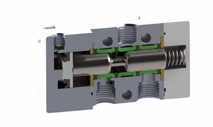
TECHNICAL CHARACTERISTICS
Component Parts and Materials
• Anodised and painted aluminium body Chemical nickel-plated spool NBR seals
13.24 01V
1/81/43/81/2 THREADED G 1/8 NPTF 1/8 G 1/4 NPTF 1/4 G 3/8 NPTF 3/8 G 1/2 NPTF 1/2 6 bar FLOW RATE with ∆p 1 bar 740 NI/min 1200 NI/min 2000 NI/min 5000 NI/min Bar OPERATING PRESSURE 0 ÷ 10 bar 0 ÷ 145 psi Bar PRESSURE DRIVE Monostable 2 ÷ 10 bar 29 ÷ 145 psi Bistable 1 ÷ 10 bar 14.5 ÷ 145 psi TEMPERATURE min -10 °C 14 °F max +60 °C 140 °F
Reference Standard 1907/2006 2011/65/CE PED 2014/68/UE ATEX 2014/34/UE Series 01V Actuation P = Pneumatic P Reactuation 0 = Monostable spring return 1 = Bistable 0 3 = 3/2 5 = 5/2 7 = 5/3 3 NO = Normally open NC = Normally closed CC = All Ports Blocked OC = Cylinder Ports Open to Exhaust PC = Cylinder Ports Pressurized 00 = Function not privided Function NC 02 = 1/8 03 = 1/4 04 = 3/8 05 = 1/2 Size 02 Thread = G N = NPTF Page 238
3/2
SINGLE AIR PILOT - SPRING RETURN
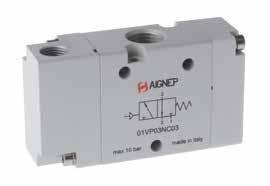
13.25 01V
Part No. Function Size Pack. 01V P0 3 NC 02 3/2 NC G 1/8 1 01V P0 3 NC 03 3/2 NC G 1/4 1 01V P0 3 NC 05 3/2 NC G 1/2 1 01V P0 3 NO 02 3/2 NO G 1/8 1 01V P0 3 NO 03 3/2 NO G 1/4 1 01V P0 3 NO 05 3/2 NO G 1/2 1 Part No. Function Size Pack. 01V P0 3 NC 02 N 3/2 NC NPTF 1/8 1 01V P0 3 NC 03 N 3/2 NC NPTF 1/4 1 01V P0 3 NC 04 N 3/2 NC NPTF 3/8 1 01V P0 3 NC 05 N 3/2 NC NPTF 1/2 1 01V P0 3 NO 02 N 3/2 NO NPTF 1/8 1 01V P0 3 NO 03 N 3/2 NO NPTF 1/4 1 01V P0 3 NO 04 N 3/2 NO NPTF 3/8 1 01V P0 3 NO 05 N 3/2 NO NPTF 1/2 1 NC NO G 1/8 - NPTF 1/8 15.5 13 13.5 59.1 M5 (metric) 10/32 UNF (NPTF) 14.9 6.3 6.3 Ø 4.2 Ø 3.1 1/8 7 17.2 16.8 23 32 16.9 22 NPTF 3/8 30 7,3 13,2 1/8 22 24,9 Ø 3,1 3/8 19,9 39 45 86,9 Ø 4,2 27 30 14 26 14 12,4 G 1/4 - NPTF 1/4 8.4 8.4 22 19.4 20.8 13.2 71.7 18 Ø 5.3 Ø 3.1 1/8 1/4 7.3 28 40 16.9 22 G 1/2 - NPTF 1/2 37.6 44 26.8 136.2 15.6 15.6 44 Ø 5.3 Ø 3.1 1/8 1/2 9 41.6 40 60 24.9 30 Page 239
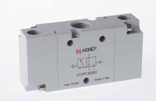
13.26 01V
DOUBLE AIR PILOT G 1/8 - NPTF 1/8 15.5 25.1 13.5 67.4 13 M5 (metric) 10/32 UNF (NPTF) Ø 4.2 Ø 3.1 1/8 7 23 32 16.9 22 14.9 6.3 17.2 6.3 NPTF 3/8 30 24,9 Ø 3,1 3/8 39 1/8 7,3 13,2 28 22 45 Ø 4,2 27 30 14 26 14 95 20,5 G 1/4 - NPTF 1/4 19.4 13.2 79.8 Ø 4.2 Ø 3.1 1/4 1/8 7.3 28 40 16.9 22 28.9 18 22 8.4 8.4 G 1/2 - NPTF 1/2 37.6 26.8 145.2 Ø 5.3 Ø 3.1 1/8 1/2 9 40 60 24.9 30 50.6 44 44 15.6 15.6 Part No. Function Size Pack. 01V P1 3 00 02 3/2 G 1/8 1 01V P1 3 00 03 3/2 G 1/4 1 01V P1 3 00 05 3/2 G 1/2 1 Part No. Function Size Pack. 01V P1 3 00 02 N 3/2 NPTF 1/8 1 01V P1 3 00 03 N 3/2 NPTF 1/4 1 01V P1 3 00 04 N 3/2 NPTF 3/8 1 01V P1 3 00 05 N 3/2 NPTF 1/2 1 Page 240
3/2
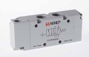
13.27 01V
G 1/8 - NPTF 1/8 31.8 13.5 76.3 Ø 4.2 Ø 3.1 M5 (metric) 10/32 UNF (NPTF) 1/8 7 23 32 16.9 22 10.5 26 13 17.2 17.2 6.3 6.3 1517 NPTF 3/8 30 32,5 32,5 19,9 24,9 3/8 3/8 Ø 3,1 13,2 7,3 1/8 14 13 26 13 14 30 45 112,9 12,4 52 Ø 4,2 20,5 G 1/4 - NPTF 1/4 45 13.2 94.9 Ø 4.2 Ø 3.1 1/8 1/4 7.3 40 60 16.9 22 18 36 2222 99 13 20 22 G 1/2 - NPTF 1/2 88 26.8 180.6 Ø 5.3 Ø 3.1 1/8 1/2 9 40 60 24.9 30 44 88 44 44 15.8 15.8 15.8 37.8 44 Part No. Function Size Pack. 01V P0 5 00 02 5/2 G 1/8 1 01V P0 5 00 03 5/2 G 1/4 1 01V P0 5 00 05 5/2 G 1/2 1 Part No. Function Size Pack. 01V P0 5 00 02 N 5/2 NPTF 1/8 1 01V P0 5 00 03 N 5/2 NPTF 1/4 1 01V P0 5 00 04 N 5/2 NPTF 3/8 1 01V P0 5 00 05 N 5/2 NPTF 1/2 1 Page 241
5/2 SINGLE AIR PILOT - SPRING RETURN
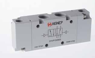
13.28 01V
DOUBLE AIR PILOT G 1/8 - NPTF 1/8 31.8 13.2 84.6 Ø 4.2 Ø 3.1 M5 (metric) 10/32 UNF (NPTF) 1/8 7 23 32 16.9 22 10.5 26 17.217.2 6.3 6.3 13 15 17 NPTF 3/8 30 32,5 32,5 28 24,9 3/8 3/8 Ø 3,1 13,2 7,3 1/8 14 13 26 13 14 30 45 121 20,5 52 Ø 4,2 20,5 G 1/4 - NPTF 1/4 36 45 13.2 103 Ø 4.2 Ø 3.1 1/8 1/4 7.5 28 40 16.9 22 13 99 2222 18 20 22 G 1/2 - NPTF 1/2 88 26.8 189.6 Ø 5.3 Ø 3.1 1/8 1/2 9 23 60 16.9 30 15.8 88 44 44 15.8 15.8 44 37.8 44 Part No. Function Size Pack. 01V P1 5 00 02 5/2 G 1/8 1 01V P1 5 00 03 5/2 G 1/4 1 01V P1 5 00 05 5/2 G 1/2 1 Part No. Function Size Pack. 01V P1 5 00 02 N 5/2 NPTF 1/8 1 01V P1 5 00 03 N 5/2 NPTF 1/4 1 01V P1 5 00 04 N 5/2 NPTF 3/8 1 01V P1 5 00 05 N 5/2 NPTF 1/2 1 Page 242
5/2
5/3
DOUBLE AIR PILOT - SPRING RETURN
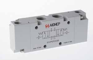
13.29 01V
Part No. Function Size Pack. 01V P0 7 CC 02 5/3 CC G 1/8 1 01V P0 7 CC 03 5/3 CC G 1/4 1 01V P0 7 CC 05 5/3 CC G 1/2 1 01V P0 7 OC 02 5/3 OC G 1/8 1 01V P0 7 OC 03 5/3 OC G 1/4 1 01V P0 7 OC 05 5/3 OC G 1/2 1 01V P0 7 PC 02 5/3 PC G 1/8 1 01V P0 7 PC 03 5/3 PC G 1/4 1 01V P0 7 PC 05 5/3 PC G 1/2 1 CC OC PC G 1/8 - NPTF 1/8 31.8 13.2 84.6 Ø 4.2 Ø 3.1 M5 (metric) 10/32 UNF (NPTF) 1/8 7 23 32 16.9 22 10.5 26 17.217.2 6.3 6.3 13 15 17 NPTF 3/8 30 32,5 32,5 28 24,9 3/8 3/8 Ø 3,1 13,2 7,3 1/8 14 13 26 13 14 30 45 121 20,5 52 Ø 4,2 20,5 G 1/4 - NPTF 1/4 36 45 13.2 103 Ø 4.2 Ø 3.1 1/8 1/4 7.5 28 40 16.9 22 13 99 2222 18 20 22 G 1/2 - NPTF 1/2 88 26.8 189.6 Ø 5.3 Ø 3.1 1/8 1/2 9 23 60 16.9 30 15.8 88 44 44 15.8 15.8 44 37.8 44 Part No. Function Size Pack. 01V P0 7 CC 02 N 5/3 CC NPTF 1/8 1 01V P0 7 CC 03 N 5/3 CC NPTF 1/4 1 01V P0 7 CC 04 N 5/3 CC NPTF 3/8 1 01V P0 7 CC 05 N 5/3 CC NPTF 1/2 1 01V P0 7 OC 02 N 5/3 OC NPTF 1/8 1 01V P0 7 OC 03 N 5/3 OC NPTF 1/4 1 01V P0 7 OC 04 N 5/3 OC NPTF 3/8 1 01V P0 7 OC 05 N 5/3 OC NPTF 1/2 1 01V P0 7 PC 02 N 5/3 PC NPTF 1/8 1 01V P0 7 PC 03 N 5/3 PC NPTF 1/4 1 01V P0 7 PC 04 N 5/3 PC NPTF 3/8 1 01V P0 7 PC 05 N 5/3 PC NPTF 1/2 1 Page 243
MANUAL VALVES
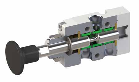
TECHNICAL
13.30 01V
1/81/4 THREADED G 1/8 NPTF 1/8 G 1/4 NPTF 1/4 6 bar FLOW RATE with ∆p 1 bar 740 NI/min1200 NI/min Bar OPERATING PRESSURE Vacuum ÷ 10 bar Vacuum ÷ 145 psi TEMPERATURE min -10 °C 14 °F max +60 °C 140 °F PANEL MOUNT M 16x1
CHARACTERISTICS Component Parts and Materials Anodised and painted aluminium body Chemical nickel-plated spool • NBR seals Reference Standard 1907/2006 2011/65/CE PED 2014/68/UE ATEX 2014/34/UE Series 01V 3 = 3/2 5 = 5/2 7 = 5/3 3 Reactuation 0 = Monostable spring return 1 = Bistable 2 = Stable in 3 positions 0 Actuation T = Button L = 90° Lever T NO = Normally open NC = Normally closed CC = All Ports Blocked OC = Cylinder Ports Open to Exhaust PC = Cylinder Ports Pressurized 00 = Function not privided Function NC 02 = 1/8 03 = 1/4 Size 02 Thread = G N = NPTF Page 244
3/2
BUTTON OPERATED - SPRING RETURN
3/2
BUTTON OPERATED - PUSH / PULL
BUTTON OPERATED VALVES
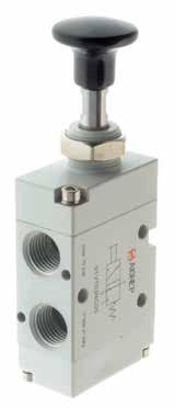
13.31 01V
Part No. Function Size Pack. 01V T0 3 NC 02 3/2 NC G 1/8 1 01V T0 3 NC 03 3/2 NC G 1/4 1 Part No. Function Size Pack. 01V T0 3 NC 02 N 3/2 NC NPTF 1/8 1 01V T0 3 NC 03 N 3/2 NC NPTF 1/4 1 Part No. Function Size Pack. 01V T1 3 00 02 3/2 G 1/8 1 01V T1 3 00 03 3/2 G 1/4 1 Part No. Function Size Pack. 01V T1 3 00 02 N 3/2 NPTF 1/8 1 01V T1 3 00 03 N 3/2 NPTF 1/4 1 G 1/8 - NPTF 1/8 Ø 4.2 23 32 14.9 15.5 62.8 8 17.2 6.3 6.3 29.5 max 8.5 13 16.8 16.9 22 Ø 3.1 1/8 CH19 G 1/4 - NPTF 1/4 22 Ø 4,2 28 40 8,4 8,4 19,4 75,6 8 30,8 max 8,5 18 20,8 16,9 22 Ø 3,1 1/4 CH19 Page 245
5/2
BUTTON OPERATED - SPRING RETURN
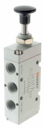
5/2
OPERATED - PUSH / PULL
13.32 01V
Part No. Function Size Pack. 01V T0 5 00 02 5/2 G 1/8 1 01V T0 5 00 03 5/2 G 1/4 1 Part No. Function Size Pack. 01V T0 5 00 02 N 5/2 NPTF 1/8 1 01V T0 5 00 03 N 5/2 NPTF 1/4 1 Part No. Function Size Pack. 01V T1 5 00 02 5/2 G 1/8 1 01V T1 5 00 03 5/2 G 1/4 1 Part No. Function Size Pack. 01V T1 5 00 02 N 5/2 NPTF 1/8 1 01V T1 5 00 03 N 5/2 NPTF 1/4 1 G 1/8 - NPTF 1/8 23 32 Ø 4,2 17 15 31,8 80 8 6,3 17,2 17,2 6,3 29,5 max 8,5 26 13 21 Ø 3,1 16,9 22 1/8 CH19 G 1/4 - NPTF 1/4 45 28 40 Ø 4,2 22 98,8 20 9 9 22 22 30,8 16,9 22 36 18 max 8,5 Ø 3,1 25,4 8 1/4 CH19 Page 246
BUTTON
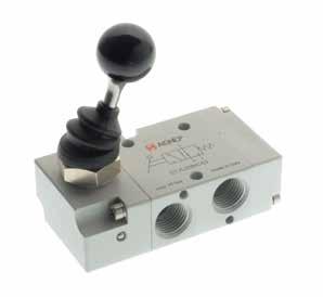
01V 13.33 3/2 LEVER OPERATED - SPRING RETURN 3/2 LEVER OPERATED - PUSH / PULL Part No. Function Size Pack. 01V L0 3 NC 02 3/2 NC G 1/8 1 01V L0 3 NC 03 3/2 NC G 1/4 1 Part No. Function Size Pack. 01V L0 3 NC 02 N 3/2 NC NPTF 1/8 1 01V L0 3 NC 03 N 3/2 NC NPTF 1/4 1 Part No. Function Size Pack. 01V L1 3 00 02 3/2 G 1/8 1 01V L1 3 00 03 3/2 G 1/4 1 Part No. Function Size Pack. 01V L1 3 00 02 N 3/2 NPTF 1/8 1 01V L1 3 00 03 N 3/2 NPTF 1/4 1 G 1/8 - NPTF 1/8 Ø 4,2 23 32 17,2 15,5 14,9 63,1 17,2 6,3 6,3 max 6 16,9 22 13 16,8 Ø 3,1 30° 75,4 1/8 CH19 G 1/4 - NPTF 1/4 22,9 8,4 22 8,4 28 Ø 4,2 19,4 75,2 1/4 40 max 6 Ø 3,1 18 20,8 16,9 22 74,9 CH19 36° 90º LEVER OPERATED VALVES Page 247
LEVER OPERATED - SPRING RETURN 5/2
01V 13.34
5/2
LEVER OPERATED - PUSH / PULL Part No. Function Size Pack. 01V L0 5 00 02 5/2 G 1/8 1 01V L0 5 00 03 5/2 G 1/4 1 Part No. Function Size Pack. 01V L0 5 00 02 N 5/2 NPTF 1/8 1 01V L0 5 00 03 N 5/2 NPTF 1/4 1 Part No. Function Size Pack. 01V L1 5 00 02 5/2 G 1/8 1 01V L1 5 00 03 5/2 G 1/4 1 Part No. Function Size Pack. 01V L1 5 00 02 N 5/2 NPTF 1/8 1 01V L1 5 00 03 N 5/2 NPTF 1/4 1 G 1/8 - NPTF 1/8 23 32 Ø 4,2 17 15 31,8 80,3 17,2 6,3 17,2 17,2 6,3 max 6 13 26 Ø 3,1 16,9 22 21 75,4 1/8 CH19 30° G 1/4 - NPTF 1/4 22 20 Ø 4,2 45 98,4 22,9 28 40 9 22 9 max 6 36 18 25,4 Ø 3,1 16,9 22 ° 6 3 74,9 1/4 22 CH19 Page 248
5/3
LEVER OPERATED - SPRING CENTERED 5/3
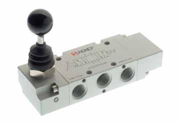
01V 13.35
LEVER OPERATED - PUSH / PULL CC OC PC CC OC PC Part No. Function Size Pack. 01V L0 7 CC 02 5/3 CC G 1/8 1 01V L0 7 CC 03 5/3 CC G 1/4 1 01V L0 7 OC 02 5/3 OC G 1/8 1 01V L0 7 OC 03 5/3 OC G 1/4 1 01V L0 7 PC 02 5/3 PC G 1/8 1 01V L0 7 PC 03 5/3 PC G 1/4 1 Part No. Function Size Pack. 01V L0 7 CC 02 N 5/3 CC NPTF 1/8 1 01V L0 7 CC 03 N 5/3 CC NPTF 1/4 1 01V L0 7 OC 02 N 5/3 OC NPTF 1/8 1 01V L0 7 OC 03 N 5/3 OC NPTF 1/4 1 01V L0 7 PC 02 N 5/3 PC NPTF 1/8 1 01V L0 7 PC 03 N 5/3 PC NPTF 1/4 1 CC OC PC CC OC PC Part No. Function Size Pack. 01V L2 7 CC 02 5/3 CC G 1/8 1 01V L2 7 CC 03 5/3 CC G 1/4 1 01V L2 7 OC 02 5/3 OC G 1/8 1 01V L2 7 OC 03 5/3 OC G 1/4 1 01V L2 7 PC 02 5/3 PC G 1/8 1 01V L2 7 PC 03 5/3 PC G 1/4 1 Part No. Function Size Pack. 01V L2 7 CC 02 N 5/3 CC NPTF 1/8 1 01V L2 7 CC 03 N 5/3 CC NPTF 1/4 1 01V L2 7 OC 02 N 5/3 OC NPTF 1/8 1 01V L2 7 OC 03 N 5/3 OC NPTF 1/4 1 01V L2 7 PC 02 N 5/3 PC NPTF 1/8 1 01V L2 7 PC 03 N 5/3 PC NPTF 1/4 1 Page 249
01V 13.36 01V L0 7 CC 02 01V L0 7 OC 02 01V L0 7 PC 02 01V L0 7 CC 02 N 01V L0 7 OC 02 N 01V L0 7 PC 02 N 23 32 Ø 4,2 17 15 31,8 17,2 93,8 6,3 17,2 17,2 6,3 max 6 13 26 Ø 3,1 16,9 22 34,5 75,4 1/8 CH19 30° 01V L0 7 CC 03 01V L0 7 OC 03 01V L0 7 PC 03 01V L0 7 CC 03 N 01V L0 7 OC 03 N 01V L0 7 PC 03 N 22 20 Ø 4,2 45 22,9 28 40 111,2 9 22 9 max 6 36 18 Ø 3,1 16,9 22 38,2 °63 74,9 1/4 22 CH19 01V L2 7 CC 02 01V L2 7 OC 02 01V L2 7 PC 02 01V L2 7 CC 02 N 01V L2 7 OC 02 N 01V L2 7 PC 02 N 23 32 Ø 4,2 17 15 31,8 80,3 17,2 6,3 17,2 17,2 6,3 max 6 13 26 Ø 3,1 16,9 22 21 75,4 1/8 CH19 30° 01V L2 7 CC 03 01V L2 7 OC 03 01V L2 7 PC 03 01V L2 7 CC 03 N 01V L2 7 OC 03 N 01V L2 7 PC 03 N 22 20 Ø 4,2 45 98,4 22,9 28 40 9 22 9 max 6 36 18 25,4 Ø 3,1 16,9 22 °63 74,9 1/4 22 CH19 Page 250
STAINLESS STEEL AISI 316 L 90° LEVER VALVE AISI 316L
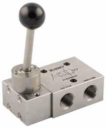
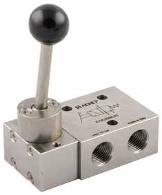
TECHNICAL CHARACTERISTICS
Reference Standard
1907/2006 2011/65/CE PED 2014/68/UE
Component Parts and Materials Stainless Steel 316 L (1.4404) body
• Stainless Steel 316 L (1.4404) spool PUR seals and FKM O-Ring
3/2 Ways MONOSTABLE SPRING RETURN
3/2 Ways TWO STABLE POSITIONS
01V 13.37
1/4 THREADED G 1/4 NPTF 1/4 Bar OPERATING PRESSURE 1 ÷ 10 bar ACTIVATION FORCE 20 N
Part No. Function Size Pack. X1V L0 3 NC 03 3/2 NC G 1/4 1 Part No. Function Size Pack. X1V L1 3 NC 03 3/2 NC G 1/4 1
Page 251
5/2 Ways
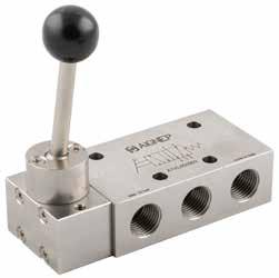
01V 13.38
MONOSTABLE SPRING RETURN
TWO STABLE POSITIONS X1V L0 3 NC 03 X1V L1 3 00 03 12 22 Ø5,5 48 22 2 1 3 10 13 M4 2213 1 14 89 G 1/4” 10 22 40 25 30 X1V L0 5 00 03 X1V L1 5 00 03 22 70 44 2224 222213 13 M4 Ø5,5 30 25 40 1 22 14 14 89 12 G 1/4” 13 5 2 12 4 Part No. Function Size Pack. X1V L0 5 00 03 5/2 G 1/4 1 Part No. Function Size Pack. X1V L1 5 00 03 5/2 G 1/4 1 Page 252
5/2 Ways
5/3 Ways
5/3 Ways
01V 13.39
MONOSTABLE SPRING RETURN
3 STABLE POSITIONS CC OC PC CC OC PC Part No. Function Size Pack. X1V L0 7 CC 03 5/3 CC G 1/4 1 X1V L0 7 OC 03 5/3 OC G 1/4 1 X1V L0 7 PC 03 5/3 PC G 1/4 1 CC OC PC Part No. Function Size Pack. X1V L2 7 CC 03 5/3 CC G 1/4 1 X1V L2 7 OC 03 5/3 OC G 1/4 1 X1V L2 7 PC 03 5/3 PC G 1/4 1 X1V L0 7 CC 03 X1V L0 7 OC 03 X1V L0 7 PC 03 X1V L2 7 CC 03 X1V L2 7 OC 03 X1V L2 7 PC 03 14 22 Ø5,5 70 22 44 24 24 10 13 M4 22 22 13 1 53 1 14 89 G 1/4” 12 22 40 25 30 Page 253
MECHANICALLY ACTUATED / SPRING RETURN VALVES
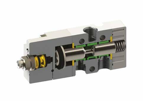
01V 13.40
1/8 THREADED G 1/8 NPTF 1/8 6 bar FLOW RATE with ∆p 1 bar 740 NI/min Bar OPERATING PRESSURE 2 ÷ 10 bar 29 ÷ 145 psi DRIVING FORCE 5.8 N TEMPERATURE min -10 °C 14 °F max +60 °C 14 °F
CHARACTERISTICS Component Parts and Materials • Anodised and painted aluminium body Chemical nickel-plated spool NBR seals Reference Standard 1907/2006 2011/65/CE PED 2014/68/UE ATEX 2014/34/UE Series 01V Reactuation 0 = Monostable spring return 0 Actuation V = Servo-piloted tappet N = Servo-piloted Whisker V 3 = 3/2 5 = 5/2 3 NC = Normally closed 00 = Function not privided Function NC Size 02 = 1/8 02 Thread = G N = NPTF Page 254
TECHNICAL
3/2
SERVO-PILOTED TAPPET - SPRING RETURN
SERVO-PILOTED TAPPET VALVES - SPRING RETURN
5/2
SERVO-PILOTED TAPPET - SPRING RETURN
The servo-piloted valve actuators are designed for panel mounting. For interfaces, refer to the buttons and switches in Series 04V Pg. 45.
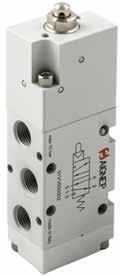
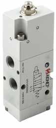
01V 13.41
04V 06 0 00 01 04V 01 0 00 01 Part No. Function Size Pack. 01V V0 3 NC 02 3/2 NC G 1/8 1 Part No. Function Size Pack. 01V V0 3 NC 02 N 3/2 NC NPTF 1/8 1 Part No. Function Size Pack. 01V V0 5 00 02 5/2 G 1/8 1 Part No. Function Size Pack. 01V V0 5 00 02 N 5/2 NPTF 1/8 1 01V V0 3 NC 02 01V V0 3 NC 02 N 23 32 Ø 4,2 14 ,9 15 ,5 4,8 4 Ø 5,7 ~ 81 6,3 17 ,2 6,3 Ø 3,1 13 16 ,8 16,9 22 1/ 8 01V V0 5 00 02 01V V0 5 00 02 N Ø 3,1 26 13 21 16,9 22 1/ 8 23 32 15 17 Ø 4,2 31 ,8 4,8 Ø 5,7 4 ~ 98 6,3 17 ,2 17 ,2 6,3
Page 255
3/2
SERVO-PILOTED WHISKER - SPRING RETURN
SERVO-PILOTED WHISKER - SPRING RETURN VALVES
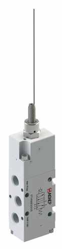
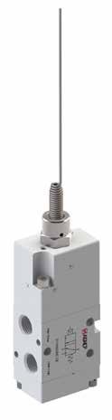
5/2
SERVO-PILOTED WHISKER - SPRING RETURN
01V 13.42
Part No. Function Size Pack. 01V N0 3 NC 02 3/2 NC G 1/8 1 Part No. Function Size Pack. 01V N0 3 NC 02 N 3/2 NC NPTF 1/8 1 Part No. Function Size Pack. 01V N0 5 00 02 5/2 G 1/8 1 Part No. Function Size Pack. 01V N0 5 00 02 N 5/2 NPTF 1/8 1 01V N0 3 NC 02 01V N0 3 NC 02 N 16,9 22 Ø 3,1 16 ,8 13 1/ 8 23 32 Ø 4,2 14 ,9 15 ,5 ~2 05 ~1 33 17 ,2 6,3 6,3 20° 20° 01V N0 5 00 02 01V N0 5 00 02 N 26 13 21 Ø 3,1 16,9 22 1/ 8 23 32 Ø 4,2 17 15 31 ,8 ~1 33 ~ 223 17 ,2 6,3 17 ,2 6,3 20° 20° Page 256
DIN RAIL MOUNTED FIXED LENGTH MANIFOLD BASES - NPTF
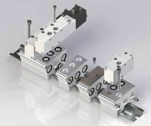
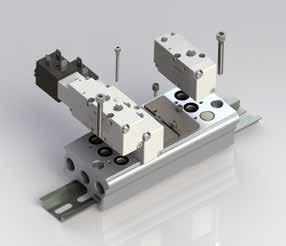
The bases are supplied with screws and O-Ring for attachment of the valves.
DIN RAIL MOUNTED MODULAR BASES
All the bases are supplied with screws and seals to sescure the correct assembly.
01V 13.43
7 25 L 26,8252523,8 10 62 40,4 1/4 NPTF 38,5 17,5 16 M5 25 26,8 2525 23,8 12,5 7 75,2 50 3/8 NPTF 38,5 17,5 16 M5 L MANIFOLD BASE FOR VALVES 01V - 1/8 NPTF Part Number Stations L Pack. 01V B0 0 00 02 N 2 76 1 01V B0 0 00 03 N 3 101 1 01V B0 0 00 04 N 4 126 1 01V B0 0 00 05 N 5 151 1 01V B0 0 00 06 N 6 176 1 01V B0 0 00 07 N 7 201 1 01V B0 0 00 08 N 8 226 1 01V B0 0 00 09 N 9 251 1 01V B0 0 00 10 N 10 276 1 MANIFOLD BASE FOR VALVES 01V - 1/4 NPTF Part Number Stations L Pack. 01V B0 1 00 02 N 2 76 1 01V B0 1 00 03 N 3 101 1 01V B0 1 00 04 N 4 126 1 01V B0 1 00 05 N 5 151 1 01V B0 1 00 06 N 6 176 1 01V B0 1 00 07 N 7 201 1 01V B0 1 00 08 N 8 226 1 01V B0 1 00 09 N 9 251 1 01V B0 1 00 10 N 10 276 1
Page 257
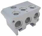
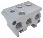
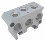
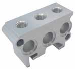
01V 13.44 01V B1 0 00 00 N 01V B3 0 00 00 N 16 1,5 38,5 20 20 4 11 37,8 17,2 17,2 62 1/4 NPTF 10 1,5 38,5 16 20 20 25 62 4 10 17 17 01V B1 0 00 01 N 01V B3 0 00 01 N 16 1,5 38,5 25 25 2,5 12 37,8 22 22 75 3/8 NPTF 12 1,5 38,5 16 25 25 25 75 2,5 10,5 22 22 01V B2 0 00 00 N 01V B4 0 00 00 N 16 1,5 38,5 20 20 37,8 62 10 4 17,2 17,2 10 1/4 NPTF 20 20 1,5 38,5 16 25 62 19 19 12,5 1/8 NPTF 01V B2 0 00 01 N 01V B4 0 00 01 N 16 1,5 38,5 25 25 37,8 75 10,5 2,5 22 22 12 3/8 NPTF 25 25 1,5 38,5 16 25 75 23,5 23,5 12,5 1/4 NPTF FRONT MANIFOLD END PLATE REAR MANIFOLD END PLATE Part Number Size Pack. 01V B1 0 00 00 N 1/8 NPTF 1 01V B1 0 00 01 N 1/4 NPTF 1 Part Number Size Pack. 01V B2 0 00 00 N 1/8 NPTF 1 01V B2 0 00 01 N 1/4 NPTF 1 MODULAR BASE INTERMEDIATE PRESSURE BASE Part Number Size Pack. 01V B3 0 00 00 N 1/8 NPTF 1 01V B3 0 00 01 N 1/4 NPTF 1 Part Number Size Pack. 01V B4 0 00 00 N 1/8 NPTF 1 01V B4 0 00 01 N 1/4 NPTF 1 Page 258
DIN RAIL MOUNTED FIXED LENGTH MANIFOLD BASES
The bases are supplied with screws and O-Ring for attachment of the valves.
DIN RAIL MOUNTED MODULAR BASES
All the bases are supplied with screws and seals to sescure the correct assembly.
01V 13.45
7 24 L 26,8242423,8 10 62 40,4 G1/4 38,5 17,5 16 M5 24 26,8 2424 23,8 12,5 7 75,2 50 G3/8 38,5 17,5 16 M5 L MANIFOLD BASE FOR VALVES 01V - G1/8 Part Number Stations L Pack. 01V B0 0 00 02 2 75 1 01V B0 0 00 03 3 99 1 01V B0 0 00 04 4 123 1 01V B0 0 00 05 5 147 1 01V B0 0 00 06 6 171 1 01V B0 0 00 07 7 195 1 01V B0 0 00 08 8 219 1 01V B0 0 00 09 9 243 1 01V B0 0 00 10 10 267 1 MANIFOLD BASE FOR VALVES 01V - G1/4 Part Number Stations L Pack. 01V B0 1 00 02 2 75 1 01V B0 1 00 03 3 99 1 01V B0 1 00 04 4 123 1 01V B0 1 00 05 5 147 1 01V B0 1 00 06 6 171 1 01V B0 1 00 07 7 195 1 01V B0 1 00 08 8 219 1 01V B0 1 00 09 9 243 1 01V B0 1 00 10 10 267 1
Page 259
01V 13.46 01V B1 0 00 00 01V B3 0 00 00 16 1,5 38,5 20 20 4 10,5 37,3 17,2 17,2 62 G1/4 11 1,5 38,5 16 20 20 24 62 4 9,5 17 17 01V B1 0 00 01 01V B3 0 00 01 16 1,5 38,5 25 25 2,5 11 37,3 22 22 75 G3/8 12 1,5 38,5 16 25 25 24 75 2,5 10 22 22 01V B2 0 00 00 01V B4 0 00 00 16 1,5 38,5 20 20 37,3 62 9,5 4 17,2 17,2 11 G1/4 20 20 1,5 38,5 16 24 62 19 19 12 G1/8 01V B2 0 00 01 01V B4 0 00 01 16 1,5 38,5 25 25 37,3 75 10 2,5 22 22 12 G3/8 25 25 1,5 38,5 16 24 75 23,5 23,5 12 G1/4 FRONT MANIFOLD END PLATE REAR MANIFOLD END PLATE Part Number Size Pack. 01V B1 0 00 00 G 1/8 1 01V B1 0 00 01 G 1/4 1 Part Number Size Pack. 01V B2 0 00 00 G 1/8 1 01V B2 0 00 01 G 1/4 1 MODULAR BASE INTERMEDIATE PRESSURE BASE Part Number Size Pack. 01V B3 0 00 00 G 1/8 1 01V B3 0 00 01 G 1/4 1 Part Number Size Pack. 01V B4 0 00 00 G 1/8 1 01V B4 0 00 01 G 1/4 1 Page 260


01V 13.47 PLUG FOR 3 WAY VALVE CONNECTION A B BLANKING PLATE A B M3 Part No. Size A B Pack. 01V B6 0 00 00 1/87.5121 01V B6 0 00 01 1/47.5141 Part No. Size A B Pack. 01V B9 0 00 00 1/850221 01V B9 0 00 01 1/462221 INTERMEDIATE PLUG FOR MODULAR BASE A B OMEGA BAR BRACKET 5,5 22 Part No. Size A B Pack. 01V B8 0 00 00 1/87.5121 01V B8 0 00 01 1/47.5141 Part No. Size Pack. 01V B7 0 00 00 1/8 - 1/4 2 TECHNICAL CHARACTERISTICS TYPE OF MOUNTING SCREW WITH EN 50222 OMEGA BAR THICKNESS - 15 mm M5 x 40 WITH EN 50222 OMEGA BAR THICKNESS - 7.5 mm M5 x 35 DIRECT ON BASE M4 x 40 Page 261
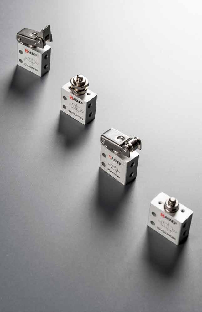
02V
Page 262
MICRO VALVES
MECHANICALLY ACTUATED MICRO VALVES
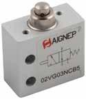
02V 13.49
M5 THREADED M5 6 bar FLOW RATE with ∆p 1 bar 100 NI/min Bar OPERATING PRESSURE 2 ÷ 10 bar 29 ÷ 145 psi DRIVING FORCE 6 N TEMPERATURE min -10 °C 14 °F max +60 °C 140 °F 3/2 TAPPET - SPRING RETURN 3/2 SHORT ROLLER - SPRING RETURN NO NC Part No. Function Size Pack. 02V G0 3 NC B5 3/2 NC M5 (metric) 1 02V G0 3 NO B5 3/2 NO M5 (metric) 1 Part No. Function Size Pack. 02V R0 3 NC B5 3/2 NC M5 (metric) 1
Component Parts and Materials • Anodised aluminium body Stainless Steel Spring NBR seals Reference Standard 1907/2006 2011/65/CE PED 2014/68/UE Series 02V Reactuation 0 = Monostable spring return 0 3 = 3/2 3 NO = Normally open NC = Normally closed Function NC B5 = M5 (metric) Size B5 Actuation G G = Tappet R = Short Roller U = Uni-directional Roller E = Panel Mounting Taper Microvalve Page 263
TECHNICAL CHARACTERISTICS
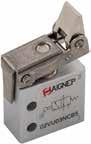
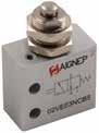
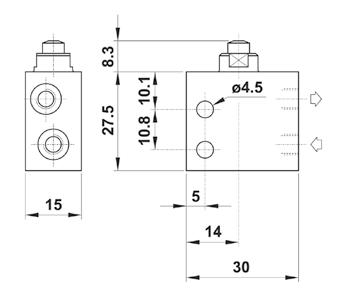
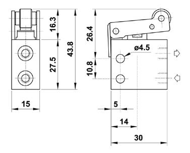
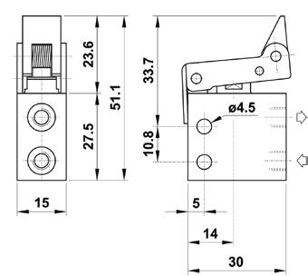
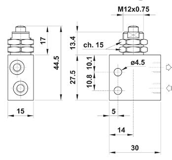
02V 13.50 3/2 UNI-DIRECTIONAL ROLLER - SPRING RETURN 3/2 PANEL MOUNTED TAPPET - SPRING RETURN Part No. Function Size Pack. 02V U0 3 NC B5 3/2 NC M5 (metric) 1 Part No. Function Size Pack. 02V E0 3 NC B5 3/2 NC M5 (metric) 1 02V G0 3 NC B5 15 02V R0 3 NC B5 02V U0 3 NC B5 02V E0 3 NC B5 15 Page 264
16 MM VALVES - MECHANICAL AND MANUAL OPERATORS
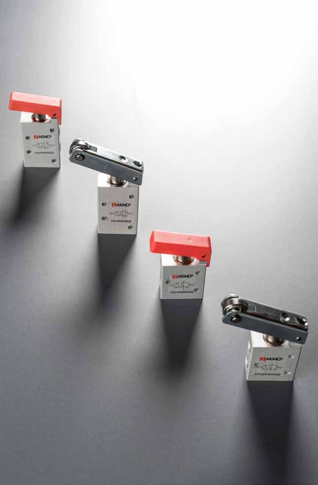
03V
Page 265
16 MM VALVES

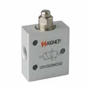
TECHNICAL CHARACTERISTICS
03V 13.52
1/8 THREADED G 1/8 6 bar FLOW RATE with ∆p 1 bar 350 NI/min Bar OPERATING PRESSURE 2 ÷ 10 bar 29 ÷ 145 psi TEMPERATURE min -10 °C 14 °F max +60 °C 140 °F 3/2 TAPPET - SPRING RETURN 5/2 TAPPET - SPRING RETURN Part No. Function Size Driving Force Pack. 03V G0 3 NC 02 3/2 NC G 1/819.6 N 1 Part No. Function Size Driving Force Pack. 03V G0 5 00 02 5/2 G 1/839.2 N 1
Component Parts and Materials • Anodised aluminium body Stainless Steel Spring NBR seals Reference Standard 1907/2006 2011/65/CE PED 2014/68/UE Series 03V Reactuation 0 = Monostable spring return 0 3 = 3/2 5 = 5/2 3 NC Normally closed 00 Function not privided Function NC 02 = 1/8 Size 02 Actuation G G = Tappet R = Short Roller H = Lever Z = Long Roller Page 266
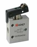
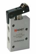

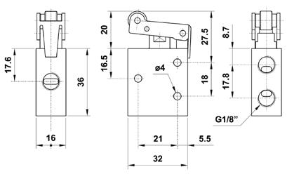
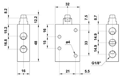
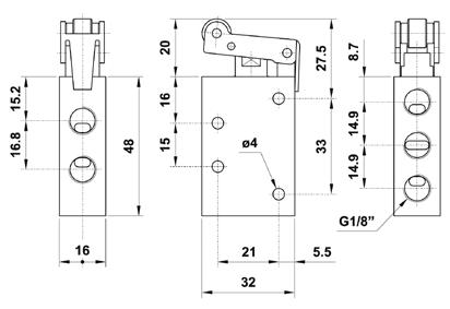
03V 13.53 3/2 SHORT ROLLER - SPRING RETURN 5/2 SHORT ROLLER - SPRING RETURN Part No. Function Size Driving Force Pack. 03V R0 3 NC 02 3/2 NC G 1/8 9.8 N 1 Part No. Function Size Driving Force Pack. 03V R0 5 00 02 5/2 G 1/821.5 N 1 03V G0 3 NC 02 03V R0 3 NC 02 03V G0 5 00 02 03V R0 5 00 02 Page 267
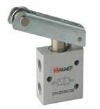
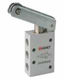
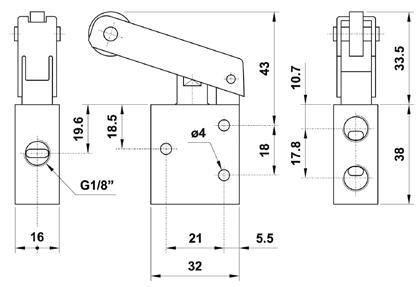
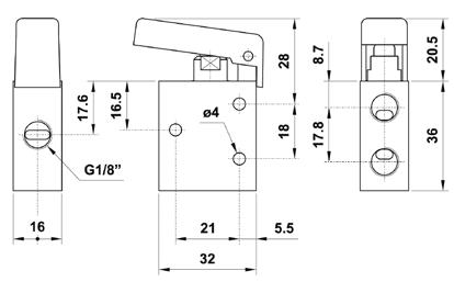
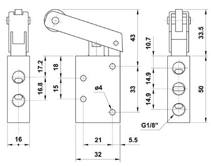
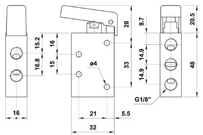
03V 13.54 3/2 LONG ROLLER - SPRING RETURN 5/2 LONG ROLLER - SPRING RETURN Part No. Function Size Driving Force Pack. 03V Z0 3 NC 02 3/2 NC G 1/8 8.3 N 1 Part No. Function Size Driving Force Pack. 03V Z0 5 00 02 5/2 G 1/814.2 N 1 3/2 LEVER OPERATED - SPRING RETURN 5/2 LEVER OPERATED - SPRING RETURN Part No. Function Size Driving Force Pack. 03V H0 3 NC 02 3/2 NC G 1/8 7.8 N 1 Part No. Function Size Driving Force Pack. 03V H0 5 00 02 5/2 G 1/813.7 N 1 03V Z0 3 NC 02 03V H0 3 NC 02 03V Z0 5 00 02 03V H0 5 00 02 Page 268
PANEL, PUSH BUTTON AND SELECTOR VALVES
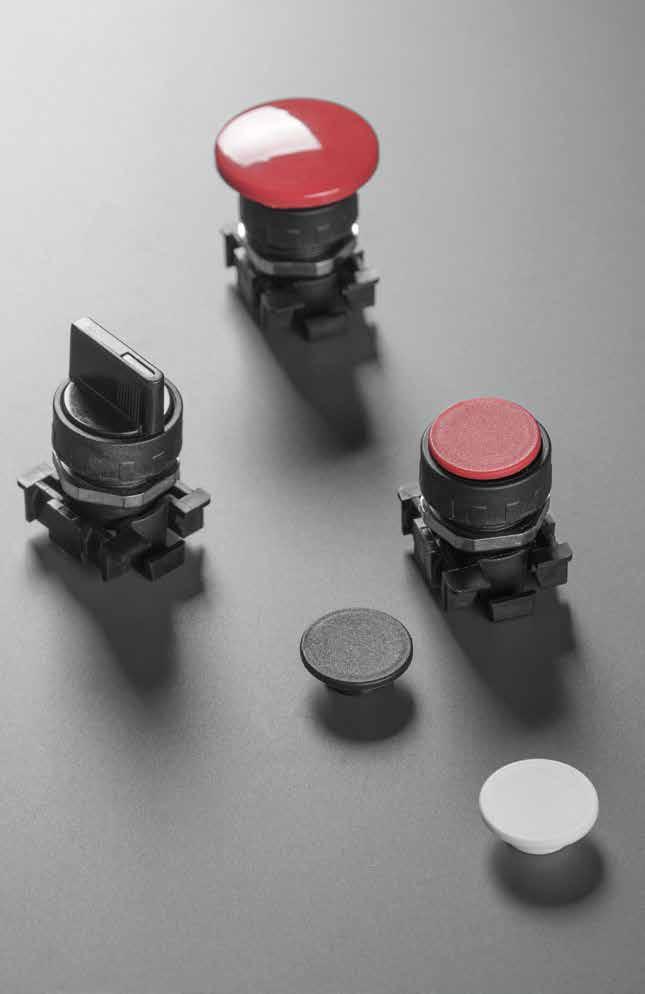
04V
Page 269
PUSH BUTTON AND SELECTOR

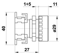
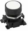
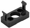
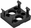
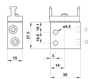
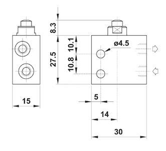

04V 13.56 3/2 TAPPET - SPRING RETURN 3/2 PANEL MOUNTED ACTUATOR - SPRING RETURN INTERFACE FOR CONNECTION BUTTON 15 NO NC Part No. Function Size Pack. 02V G0 3 NC B5 3/2 NC M5 (metric) 1 02V G0 3 NO B5 3/2 NO M5 (metric) 1 15 NO NC Part No. Function Size Pack. 02V D0 3 NC B5 3/2 NC M5 (metric) 1 02V D0 3 NO B5 3/2 NO M5 (metric) 1 04V 06 0 00 02 04V 06 0 00 01 Part No. Pack. 04V 06 0 00 01 SINGLE 1 04V 06 0 00 02 DOUBLE 1 MICRO
VALVES
PROTECTED PUSH BUTTON Part No. Standard Color Pack. 04V 01 0 00 01 1 Part No. Color Pack. 04V 01 P 00 VE 1 04V 01 P 00 GI 1 04V 01 P 00 AZ 1 The following colors can be ordered separately. Page 270
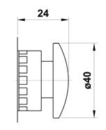
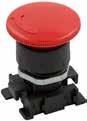
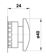
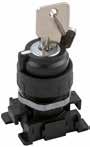
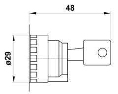
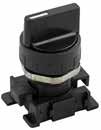
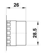
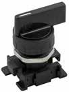
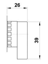
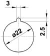
04V 13.57
TURN TO UNLOCK MUSHROOM KEY SELECTOR SHORT LEVER SELECTOR LONG LEVER SELECTOR Part No. Color Pack. 04V 02 0 0N 01 1 04V 02 0 0R 01 1 Part No. Color Pack. 04V 02 0 0R 02 1 Part No. Color Function Position to pull the key out Pack. 04V 03 0 00 01 0 - 1 Only in central position 1 04V 03 0 00 02 0 - 1 Both position 1 04V 03 0 00 03 2 - 0 - 1 Only in central position 1 Part No. Color Function Pack. 04V 04 0 0N 01 011 04V 04 0 0N 02 011 04V 04 0 0N 03 2011 04V 04 0 0N 04 2011 Part No. Color Function Pack. 04V 05 0 0N 01 01 1 04V 05 0 0N 02 01 1 04V 05 0 0N 03 201 1 04V 05 0 0N 04 201 1
AXIAL MONO-STABLE MUSHROOM
Page 271
Panel mounting hole with antirotation feature.
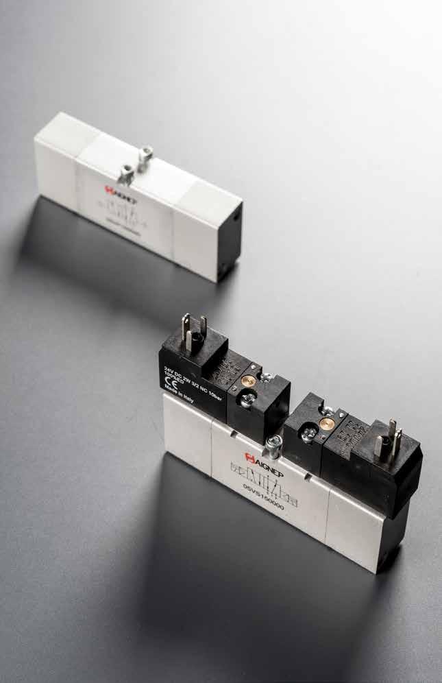
05V 18 MM VDMA VALVES Page 272
TECHNICAL CHARACTERISTICS
18 MM SOLENOID PILOT VALVES - VDMA

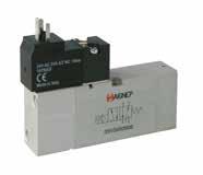
05V 13.59
6 bar FLOW RATE with ∆p 1 bar 550 NI/min Bar OPERATING PRESSURE Monostable 2.5 ÷10 bar 36.5 ÷ 145 psi Bistable 1 ÷ 10 bar 14.5 ÷ 145 psi TEMPERATURE min -10 °C 14 °F max +60 °C 140 °F V SOLENOID VOLTAGE 24V DC ÷ 24V AC W MINIMUM POWER 2W - 3VA MANUAL CONTROL MONOSTABLE Response time Monostable TRA = 13 ms TRR = 26 ms Bistable TRA=TRR = 24 ms ISO 15407-1 VDMA 24563 SIZE 02 (18 mm) TRA = Response time with energised coil TRR = Response time with deenergised coil
Component Parts and Materials Anodised aluminium body Nickel-plated spool • NBR seals Reference Standard 1907/2006 2011/65/CE PED 2014/68/UE Series 05V Reactuation 0 = Monostable spring return 1 = Bistable 0 Actuation S = Solenoid S 3 = 3/2 5 = 5/2 7 = 5/3 7 CC = All Ports Blocked OC = Normally exhausted 00 = Function not privided Function CC 00 = 24V DC 01 = 24V AC Size 00 5/2 SINGLE SOLENOID PILOT - SPRING RETURN Part No. Function Solenoid Pack. 05V S0 5 00 00 5/2 24V DC 1 05V S0 5 00 01 5/2 24V 50/60Hz 1 Page 273
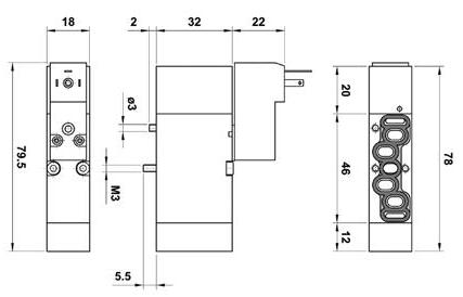
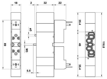
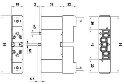
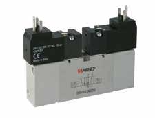
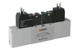
05V 13.60 05V S0 5 00 00 05V S0 5 00 01 05V S0 7 CC 00 05V S0 7 OC 00 05V S0 7 CC 01 05V S0 7 OC 01 05V S1 5 00 00 05V S1 5 00 01 5/2 DOUBLE SOLENOID PILOT 5/3 DOUBLE SOLENOID PILOT - SPRING CENTERED Part No. Function Solenoid Pack. 05V S1 5 00 00 5/2 24V DC 1 05V S1 5 00 01 5/2 24V 50/60Hz 1 CC OC PC Part No. Function Solenoid Pack. 05V S0 7 CC 00 5/3 CC 24V DC 1 05V S0 7 OC 00 5/3 OC 24V DC 1 05V S0 7 CC 01 5/3 CC 24V 50/60Hz 1 05V S0 7 OC 01 5/3 OC 24V 50/60Hz 1 Page 274
Connectors 15 mm
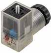
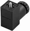
05V 13.61
CABLE DIAMETER 4 ÷ 6 mm TERMINALS DIN 4365 C DEGREE OF PROTECTION IP65 IEC 60529 Part No. Color Characteristics Pack. CON11 000 01 STANDARD 2 PIN 1 CON12 024 00 LED + VDR 0 - 24V 1 Black Transparent VDR: Fitted with varistors as surge protection device. 3.3 Ø 15.3 M2.5 15.5 15.5 8 26 28.3 CON12 024 00 VDR R LED 2 1 RED CON11 000 01 2 1 Wiring Page 275
18 MM AIR PILOT VALVES
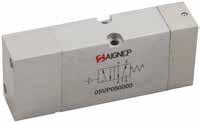

05V 13.62
6 bar FLOW RATE with ∆p 1 bar 550 NI/min Bar PRESSURE DRIVE 0 ÷ 10 bar 0 ÷ 145 psi Bar OPERATING PRESSURE Monostable 2 ÷ 10 bar 29 ÷ 145 psi Bistable 1 ÷ 10 bar 14.5 ÷ 145 psi TEMPERATURE min -10 °C 14 °F max +60 °C 140 °F RESPONSE TIME Monostable TRA = 12 ms TRR = 24 ms Bistable TRA=TRR = 21 ms ISO 15407-1 VDMA 24563 SIZE 02 (18 mm) TRA = Response time with energised coil TRR = Response time with deenergised coil
Component Parts and Materials Anodised aluminium body Nickel-plated spool • NBR seals Reference Standard 1907/2006 2011/65/CE PED 2014/68/UE 5/2 SINGLE AIR PILOT - SPRING RETURN Part No. Function Pack. 05V P0 5 00 00 5/2 1 Series 05V Reactuation 0 = Monostable spring return 1 = Bistable 0 Actuation P = Pneumatic P 5 = 5/2 7 = 5/3 5 CC = All Ports Blocked OC = Normally exhausted 00 = Function not privided Function 00 Size 00 Page 276
TECHNICAL CHARACTERISTICS
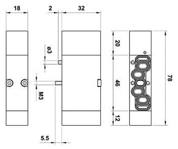

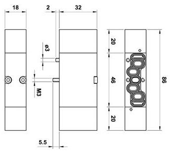
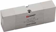
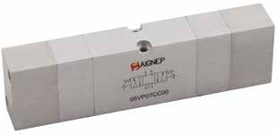
05V 13.63 05V P0 5 00 00 05V P0 7 CC 00 05V P0 7 OC 00 05V P1 5 00 00 5/2 DOUBLE AIR PILOT 5/3 DOUBLE AIR PILOT - SPRING CENTERED Part No. Function Pack. 05V P1 5 00 00 5/2 1 CC OC Part No. Function Pack. 05V P0 7 CC 00 5/3 CC 1 05V P0 7 OC 00 5/3 OC 1 Page 277
MODULAR BASES AND ACCESSORIES
All the bases are supplied with screws and seals to secure the correct assembly.
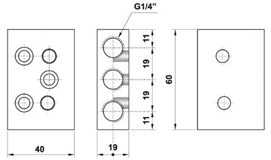
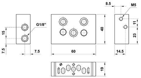
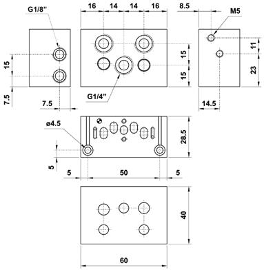
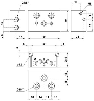
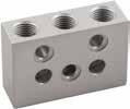
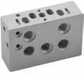
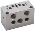
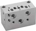
05V 13.64
FRONT MANIFOLD END PLATE REAR MANIFOLD END PLATE Part No. Pack. 05V B1 0 00 00 1 Part No. Pack. 05V B2 0 00 00 1 MODULAR BASE INTERMEDIATE PRESSURE BASE Part No. Pack. 05V B3 0 00 00 1 Part No. Pack. 05V B4 0 00 00 1 05V B1 0 00 00 05V B2 0 00 00 05V B3 0 00 00 05V B4 0 00 00 Page 278
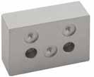
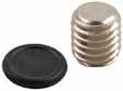
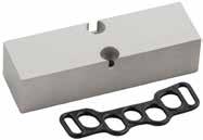
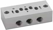
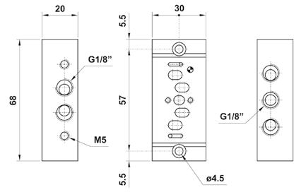
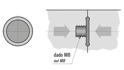
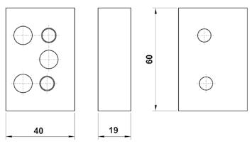
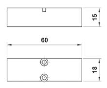
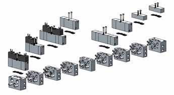
05V 13.65 INTERMEDIATE PLUG GASKET FOR INTERMEDIATE PLUG Part No. Pack. 05V B8 0 00 00 1 The gasket is supplied with M8 dowel. Part No. Pack. 05V B7 0 00 00 1 BLANKING PLATE INDIVIDUAL BASE Part No. Pack. 05V B9 0 00 00 1 Part No. Pack. 05V B5 0 00 00 1 05V B5 0 00 00 05V B7 0 00 00 Dowel 05V B8 0 00 00 05V B9 0 00 00
Page 279
Example of assembling
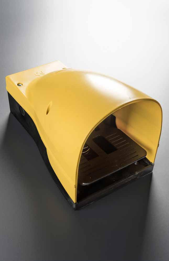
06V
Page 280
PEDAL VALVES
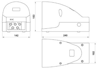
06V 13.67 1/4 THREADED G 1/4 Bar OPERATING PRESSURE 2 ÷ 10 bar 29 ÷ 145 psi TEMPERATURE max +60 °C 140 °F PROTECTION TECHNOPOLYMER Flow Rates 200 300 400 500 700 800 900 1000 1100 1200 600 100 0 00.5 22.533.5 11.5 44.5 55.5 66.57 Functions SUPPLY = 1 OUTPUT = 2 4 EXHAUST = 3 5 5/2 3/2 SUPPLY = 1 OUTPUT = 2 4 EXHAUST = 3 5 Nl/min Flow bar Pressures Nl/min bar Reference Standard 1907/2006 2011/65/CE PED 2014/68/UE 5/2 PEDAL WITH PROTECTION COVER - SPRING RETURN 5/2 PEDAL WITH PROTECTION COVER AND SAFETY FEATURE - SPRING RETURN Part No. Function Size Pack. 06V 00 0 00 01 5/2 G 1/4 1 Part No. Function Size Pack. 06V 00 0 00 02 5/2 G 1/4 1 5/2 PEDAL WITH PROTECTION COVER DETENT - SPRING RETURN 5/2 PEDAL WITH DETENT AND SAFETY LOCK - SPRING RETURN Part No. Function Size Pack. 06V 00 0 00 03 5/2 G 1/4 1 Part No. Function Size Pack. 06V 00 0 00 04 5/2 G 1/4 1 RESET Page 281
SOLENOID VALVES
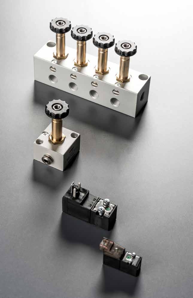
07V
Page 282
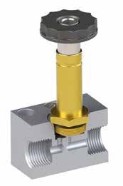
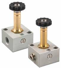
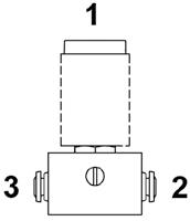
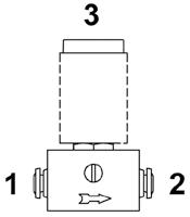
07V 13.69 THREADED G 1/8 - automatic Ø 5/32 - (4) 6 bar FLOW RATE with ∆p 1 bar 30 NI/min Bar OPERATING PRESSURE 0 ÷ 10 bar 0 ÷ 145 psi TEMPERATURE min -10 °C 14 °F max +60 °C 140 °F V SOLENOID VOLTAGE 24V DC - 12V DC - 24V AC 110V AC - 220V AC W MINIMUM POWER 3W - 5VA MANUAL CONTROL BISTABLE TORQUE OF TIGHTENING THE NUT SOLENOID 0.6 Nm 3/2 SOLENOID WITH MANUAL OVERRIDE SOLENOID WITH MANUAL OVERRIDE Part No. Function Size Pack. 07V S0 3 NC 02 3/2 NC G 1/8 1 07V S0 3 NC X1 3/2 NC Ø 5/32 (4) 1 07V S0 3 NO 02 3/2 NO G 1/8 1 07V S0 3 NO X1 3/2 NO Ø 5/32 (4) 1 * 07V Y0 3 NC 02 3/2 NC G 1/8 1 * Vacuum 22 31 31 NC NO TECHNICAL CHARACTERISTICS Component Parts and Materials • Anodised aluminium body NBR seals ATEX 2014/34/UE Reference Standard 1907/2006 2011/65/CE PED 2014/68/UE Series 07V ActuationReactuation S = Solenoid with manual override 0 = Monostable spring return S0 3 = 3/2 3 NO = Normally open NC = Normally closed Function NC 02 = 1/8 X1 = Ø 5/32 (4) Size 02 Page 283
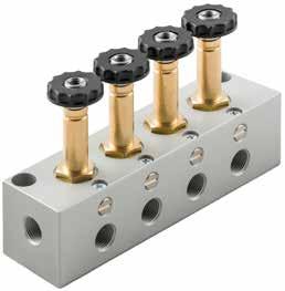
07V 13.70 5/32 - (4) 39 Ø 3.2 Ø 5/32 (4) 30 22 22 30 56.2 M5 (metric) 20 9 G1/8 Ø 3.2 30 22 22 30 G 1/8 56.2 20 9 M5 (metric) FIXED LENGTH MANIFOLD WITH MANUAL OVERRIDE SOLENOID VALVES ON FIXED LENGTH MANIFOLD Part No. Function B L Size Pack. 07V B0 0 00 02 25566 G 1/8 1 07V B0 0 00 03 377.588.5 G 1/8 1 07V B0 0 00 04 4100111 G 1/8 1 07V B0 0 00 05 5122.5133.5 G 1/8 1 07V B0 0 00 06 6145156 G 1/8 1 07V B0 0 00 07 7167.5178.5 G 1/8 1 07V B0 0 00 08 8190201 G 1/8 1 07V B0 0 00 09 9212.5223.5 G 1/8 1 07V B0 0 00 10 10235246 G 1/8 1 22 31 31 NC NO 10,4 21,75 22,5 22,5 22,5 21,75 L 5,5 24,5 30 5,5 5,5 B Ø 5,1 G1/8 M5 16 16 66 30 G1/8 See Pg. 13.20 - 13.23 SOLENOIDS AND CONNECTORS Page 284
TECHNICAL CHARACTERISTICS
10 MM MINIATURE SOLENOID VALVES
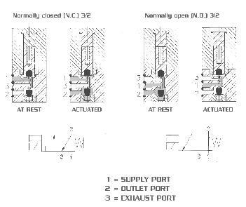
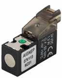
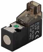
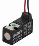
07V 13.71
Bar MAX PRESSURE Vacuum ÷ 7 bar Vacuum ÷ 101.5 psi TEMPERATURE - 5 ÷ 50 °C 23 ÷ 122 °F 6 bar FLOW RATE with ∆p 1 bar 14 NI/min EXHAUST FLOW 22 NI/min ORIFICE SIZE 0.7 mm Min MAX NUMBER OF CYCLES PER MINUTE 2700 LIFE EXPECTANCY 50 MILION CYCLES V VOLTAGE 12 V DC ÷ 24V DC W POWER 1.3 W V VOLTAGE TOLLERANCE -5% +10% RESPONSE TIME WHEN ENERGIZED 8 ms RESPONSE TIME WHEN DE-ENERGIZED 10 ms CLASS OF PROTECTION F (155 °C) F (311°F) Vacuum: NORMALLY CLOSED (NC) 3/2 NORMALLY OPEN (NO) 3/2 1 EXH 1 3 2 1 3 2 3 1 2 3 1 2 2 OUT 3 IN 2 31 2 31 AT REST ACTUATED AT REST ACTUATED
Reference Standard 1907/2006 2011/65/CE PED 2014/68/UE Series 07V Actuation 1 = 10 mm 1 3 = 3/2 3 NO = Normally open NC = Normally closed Function NC 0 = 0.7 mm Orifice size 0 0 = 12 V DC 1 = 24 V DC Voltage 0 Reactuation 1 1 = line connector + led 2 = 90° connector + led 3 = Cable (300 mm) Page 285
3/2 10 MM SOLENOID VALVE WITH LINE CONNECTOR + LED
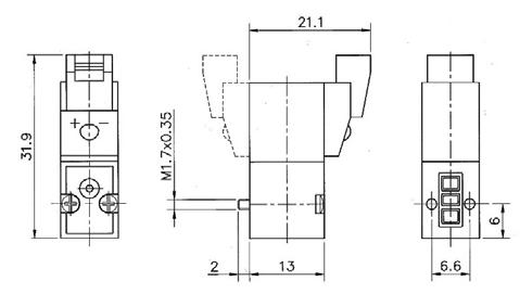
3/2 10 MM SOLENOID VALVE WITH 90º CONNECTOR + LED
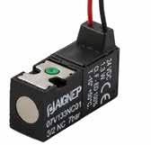
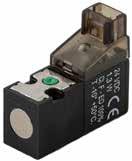
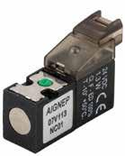
3/2 10 MM SOLENOID VALVE WITH CABLE (300 MM)
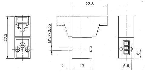
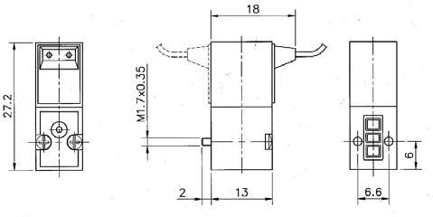
07V 13.72
IP50 Part No. Function Vacuum Solenoid Pack. 07V 11 3 NC 01 3/2 NCNO 24V DC 1 07V 11 3 NC 00 3/2 NCNO 12V DC 1 07V 11 3 NO 01 3/2 NONC 24V DC 1 07V 11 3 NO 00 3/2 NONC 12V DC 1 Item integrated with surge protector. IP50 Part No. Function Vacuum Solenoid Pack. 07V 12 3 NC 01 3/2 NCNO 24V DC 1 07V 12 3 NC 00 3/2 NCNO 12V DC 1 07V 12 3 NO 01 3/2 NONC 24V DC 1 07V 12 3 NO 00 3/2 NONC 12V DC 1 Item integrated with surge protector.
IP65 Part No. Function Vacuum Solenoid Pack. 07V 13 3 NC 01 3/2 NCNO 24V DC 1 07V 13 3 NC 00 3/2 NCNO 12V DC 1 07V 13 3 NO 01 3/2 NONC 24V DC 1 07V 13 3 NO 00 3/2 NONC 12V DC 1 Item integrated with surge protector. 07V 11 3 NC 01 07V 11 3 NC 00 07V 11 3 NO 01 07V 11 3 NO 00 07V 13 3 NC 01 07V 13 3 NC 00 07V 13 3 NO 01 07V 13 3 NO 00 07V 12 3 NC 01 07V 12 3 NC 00 07V 12 3 NO 01 07V 12 3 NO 00 Page 286
INDIVIDUAL AND FIXED LENGTH MANIFOLD BASES
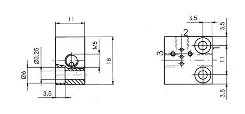
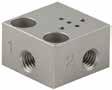
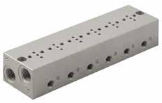
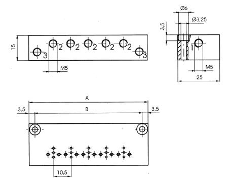
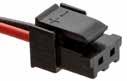
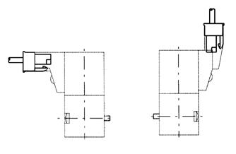
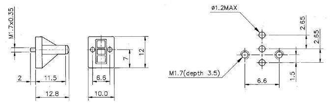
07V 13.73
BLANKING PLATE CONNECTOR WITH PVC CABLE Part No. Stations A B Pack. 07V 1B 0 00 01 1 - -1 07V 1B 0 00 02 2 39.5 32.51 07V 1B 0 00 06 6 81.5 74.51 07V 1B 0 00 08 8 102.5 95.51 Part No. Pack. 07V B1 9 00 00 1 Part No. Cable Length Characteristics Pack. CON 21 0 24 00 500 mm 0÷24v 1 CON 21 0 24 01 1000 mm 0÷24v 1 Page 287
15 MM MINIATURE SOLENOID VALVES
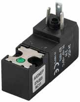
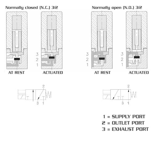
07V 13.74
Bar OPERATING PRESSURE NO 0 ÷ 7 bar 0 ÷ 101.5 psi NC 0 ÷ 10 bar 0 ÷ 145 psi TEMPERATURE - 5 ÷ 50 °C 23 °F ÷ 122 °F 6 bar FLOW RATE with ∆p 1 bar 30 NI/min ORIFICE SIZE 1.1 mm LIFE EXPECTANCY 50 MILION CYCLES V VOLTAGE 12 V DC ÷ 24V DC W POWER 2.3 W V VOLTAGE TOLLERANCE -5% +10% RESPONSE TIME WHEN ENERGIZED 10 ÷ 12 ms PROTECTION DEGREE IP50 WITH CONNECTOR CLASS OF PROTECTION F (155 °C) F (311°F) Vacuum: NORMALLY CLOSED (NC) 3/2 NORMALLY OPEN (NO) 3/2 1 EXH 3 2 1 3 2 1 3 2 1 3 2 1 2 OUT 3 IN 2 31 2 31 AT RESTACTUATED AT RESTACTUATED TECHNICAL CHARACTERISTICS ISO 15218 Reference Standard 1907/2006 2011/65/CE PED 2014/68/UE Series 07V Actuation 2 = 15 mm 2 3 = 3/2 3 NO = Normally open NC = Normally closed Function NC 1 = 1.1 mm Orifice size 1 0 = 12 V DC 1 = 24 V DC Voltage 0 Reactuation 0 0 = For terminals DIN 43650C Page 288
3/2
15 MM SOLENOID VALVE WITH TERMINALS (DIN 43650C)
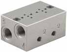
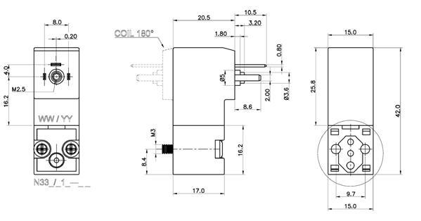
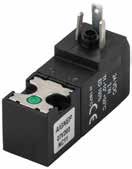
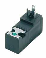
INDIVIDUAL AND FIXED LENGTH MANIFOLD BASES
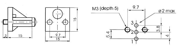
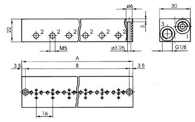
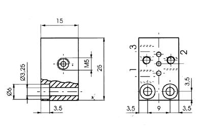
07V 13.75
Part No. Function Vacuum Solenoid Pack. 07V 20 3 NC 11 3/2 NCNO 24V DC 1 07V 20 3 NC 10 3/2 NCNO 12V DC 1 07V 20 3 NO 11 3/2 NONC 24V DC 1 07V 20 3 NO 10 3/2 NONC 12V DC 1
BLANKING PLATE Part No. Stations A B Pack. 07V 2B 0 00 01 1 - -1 07V 2B 0 00 02 2 44 371 07V 2B 0 00 06 6 108 1011 07V 2B 0 00 08 8 140 1331 Part No. Pack. 07V 2B 9 00 00 1 See Pg. 13.20 CONNECTORS Page 289
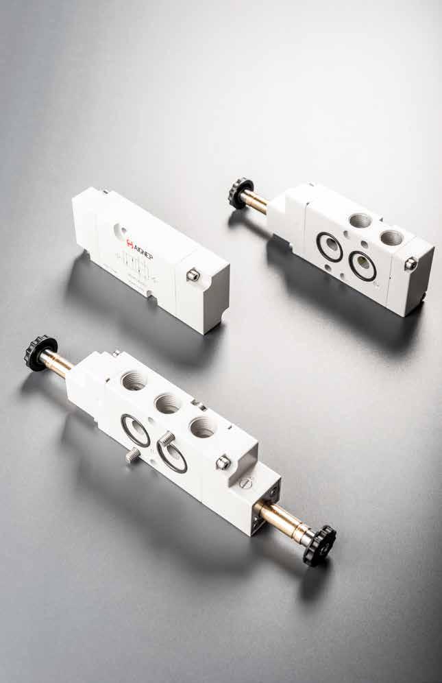
08V NAMUR VALVES Page 290
SOLENOID PILOT VALVES
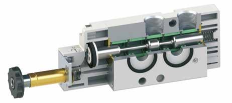
TECHNICAL CHARACTERISTICS
3845
Component Parts and Materials
• Anodised and painted aluminium body Chemical nickel-plated spool
Schematic diagram of the valve NAMUR 4/2
To prevent the return phase of the external dirty air enters the chamber in the cylinder, the air escaping from the chamber B is routed to the same room.
08V 13.77
1/4 THREADED G 1/4 - NPTF 1/4 6 bar FLOW RATE with ∆p 1 bar 1200 NI/min Bar OPERATING PRESSURE Monostable 2 ÷ 10 bar 29 ÷ 145 psi Bistable 1 ÷ 10 bar 14.5 ÷ 145 psi TEMPERATURE min -10 °C 14 °F max +60 °C 140 °F V SOLENOID VOLTAGE 24V DC - 12V DC - 24V AC 110V AC - 220V AC W MINIMUM POWER 2W - 3VA MANUAL CONTROL BISTABLE TORQUE OF TIGHTENING THE NUT SOLENOID 0.6 Nm VDI/VDE
12 12 12 3 3 3 1 1 1 4 4 4 2 2 2 A B A B
NBR seals Reference Standard 1907/2006 2011/65/CE PED 2014/68/UE ATEX 2014/34/UE Series 08V Reactuation 0 = Monostable spring return 1 = Bistable 0 Actuation S = Solenoid S 4 = 4/2 5 = 5/2 4 NC = Normally closed 00 = Function not privided Function NC 03 = 1/4 Size 03 Thread = G N = NPTF Page 291
4/2
SINGLE SOLENOID PILOT - SPRING RETURN 4/2
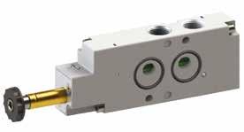
08V 13.78
DOUBLE SOLENOID PILOT 08V S0 4 NC 03 08V S0 4 NC 03 N 11 22 22 9 3 4 1/4 90° 34,2 Ø 5,2 24 104 40 19 Ø 5,5 32 20 24 19 Ø 5,2 32 24 31,4 08V S1 4 00 03 08V S1 4 00 03 N 11 22 22 9 4 3 1/4 90° 34,2 Ø 5,2 24 32 40 19 121,2 34,2 Ø 5,5 20 24 19 Ø 5,2 32 24 48,6 Part No. Function Size Pack. 08V S0 4 NC 03 4/2 NC G 1/4 1 Part No. Function Size Pack. 08V S0 4 NC 03 N 4/2 NC NPTF 1/4 1 Part No. Function Size Pack. 08V S1 4 00 03 4/2 G 1/4 1 Part No. Function Size Pack. 08V S1 4 00 03 N 4/2 NPTF 1/4 1 Page 292
5/2
SINGLE SOLENOID PILOT - SPRING RETURN
5/2
DOUBLE SOLENOID PILOT
SOLENOIDS AND CONNECTORS
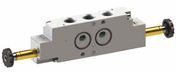
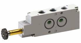
08V 13.79
08V S0 5 00 03 08V S0 5 00 03 N 22 22 9 4 3 11 22 9 1/ 4 90° 34,2 Ø 5,2 24 104 40 19 32 20 24 19 Ø 5,5 32 31,4 08V S1 5 00 03 08V S1 5 00 03 N 22 22 9 4 3 22 9 11 1/ 4 90° 34,2 Ø 5,2 24 32 40 19 121,2 34,2 24 19 20 Ø 5,5 32 48,6 Part No. Function Size Pack. 08V S0 5 00 03 5/2 G 1/4 1 Part No. Function Size Pack. 08V S0 5 00 03 N 5/2 NPTF 1/4 1 Part No. Function Size Pack. 08V S1 5 00 03 5/2 G 1/4 1 Part No. Function Size Pack. 08V S1 5 00 03 N 5/2 NPTF 1/4 1
See Pg. 13.20 - 13.23
Page 293
TECHNICAL CHARACTERISTICS
Component Parts and Materials
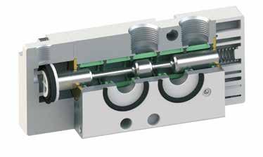
Anodised and painted aluminium body Chemical nickel-plated spool
• NBR seals
To
08V 13.80 AIR PILOT VALVES VDI/VDE
3845
Schematic diagram of the valve NAMUR 4 / 2
12 12 12 3 3 3 1 1 1 4 4 4 2 2 2 A B A B
prevent the return phase of the external dirty air enters the chamber in the cylinder, the air escaping from the chamber B is routed to the same room.
Reference Standard 1907/2006 2011/65/CE PED 2014/68/UE ATEX 2014/34/UE 1/4 THREADED G 1/4 - NPTF 1/4 6 bar FLOW RATE with ∆p 1 bar 1200 NI/min Bar OPERATING PRESSURE 0 ÷ 10 bar 0 ÷ 145 psi Bar PRESSURE DRIVE Monostable 2 ÷ 10 bar 29 ÷ 145 psi Bistable 1 ÷ 10 bar 14.5 ÷ 145 psi TEMPERATURE min -10 °C 14 °F max +60 °C 140 °F Series 08V Reactuation 0 = Monostable spring return 1 = Bistable 0 Actuation P = Pneumatic P 4 = 4/2 5 = 5/2 4 NC = Normally closed 00 = Function not privided Function NC 03 = 1/4 Size 03 Thread = G N = NPTF Page 294

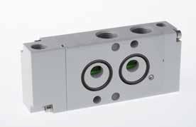
08V 13.81 4/2 SINGLE AIR PILOT - SPRING RETURN 4/2 DOUBLE AIR PILOT 08V P0 4 NC 03 08V P0 4 NC 03 N 94.9 24 2419 922 1/8 1/4 31.4 13.2 19 20 7.3 11 22 32 4 32 40 3 Ø 5.2 Ø 5.5 08V P1 4 00 03 08V P1 4 00 03 N 103 2419 Ø 5.2 Ø 5.5 2419 20 32 40 9 1/8 22 1/8 1/4 13.2 7.3 11 22 4 39.5 32 Part No. Function Size Pack. 08V P0 4 NC 03 4/2 NC G 1/4 1 Part No. Function Size Pack. 08V P0 4 NC 03 N 4/2 NC NPTF 1/4 1 Part No. Function Size Pack. 08V P1 4 00 03 4/2 G 1/4 1 Part No. Function Size Pack. 08V P1 4 00 03 N 4/2 NPTF 1/4 1 Page 295
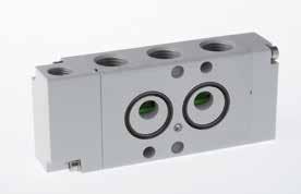
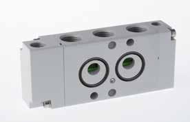
08V 13.82
AIR PILOT
5/2 DOUBLE AIR PILOT 08V P0 5 00 03 08V P0 5 00 03 N 94.9 19 24 Ø 5.2 Ø 5.5 20 32 40 2419 9 9 22 22 1/8 1/4 13.2 31.4 7.3 11 22 32 4 3 08V P1 5 00 03 08V P1 5 00 03 N 103 2419 Ø 5.2 Ø 5.5 2419 20 32 40 9 9 22 22 1/8 1/4 13.2 7.3 11 22 4 3 31.4 32 1/8 Part No. Function Size Pack. 08V P0 5 00 03 5/2 G 1/4 1 Part No. Function Size Pack. 08V P0 5 00 03 N 5/2 NPTF 1/4 1 Part No. Function Size Pack. 08V P1 5 00 03 5/2 G 1/4 1 Part No. Function Size Pack. 08V P1 5 00 03 N 5/2 NPTF 1/4 1
Page 296
5/2 SINGLE
- SPRING RETURN
See Pg. 13.20 - 13.23 SOLENOIDS AND CONNECTORS
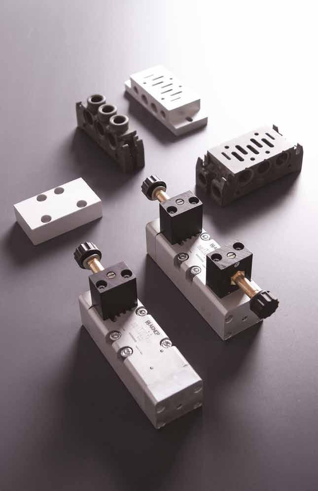
10V
ISO 5599
1 Page 297
VALVES
- SIZE
TECHNICAL CHARACTERISTICS
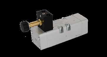
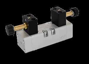

10V 13.84 6 bar FLOW RATE with ∆p 1 bar 1100 NI/min Bar OPERATING PRESSURE Monostable 2.5 ÷ 10 bar 36.2 ÷ 145 psi Bistable 1 ÷ 10 bar 14.5 ÷ 145 psi TEMPERATURE min -10 °C 14 °F max +60 °C 140 °F W MINIMUM POWER 3W - 5VA MANUAL CONTROL Two stable positions RESPONSE TIME Monostable TRA = 24 ms TRR = 50 ms Bistable TRA=TRR = 80 ms ISO 5599 SIZE 1 TRA = Response time with energised coil TRR = Response time with deenergised coil
Reference Standard 1907/2006 2011/65/CE PED 2014/68/UE Series 10V Reactuation 0 = Monostable spring return 1 = Bistable 0 Actuation S = Solenoid S 5 = 5/2 7 = 5/3 7 CC = Normally closed OC = Normally exhausted PC = Normally pressurized 00 = Function not privided Ways CC Function Component Parts and Materials • Anodised aluminium body Nickel-plated spool • NBR seals 5/2 MONOSTABLE SPRING RETURN Part No. Ways Pack. 10V S0 5 00 00 5/2 1 00 Page 298
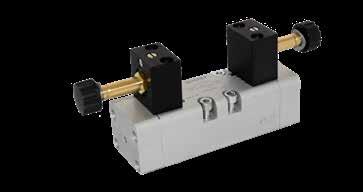
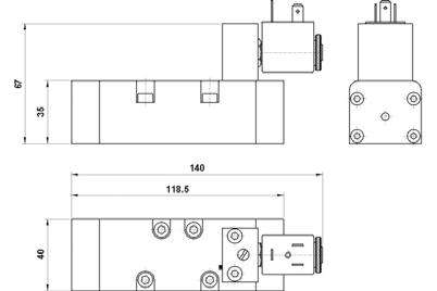
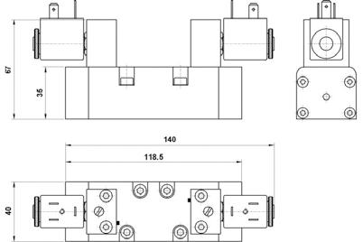
10V 13.85 5/2 TWO STABLE POSITIONS 5/3 MONOSTABLE SPRING RETURN CC OC PC CC OC PC CC OC PC Part No. Ways Pack. 10V S1 5 00 00 5/2 1 Part No. Ways Function Pack. 10V S0 7 CC 00 5/3 CC 1 10V S0 7 OC 00 5/3 OC 1 10V S0 7 PC 00 5/3 PC 1 10V S0 5 00 00 10V S1 5 00 00 10V S0 7 OC 00 10V S0 7 CC 00 10V S0 7 PC 00 Page 299
All the bases are supplied with screws and seals to secure the correct assembly.
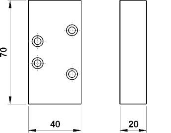
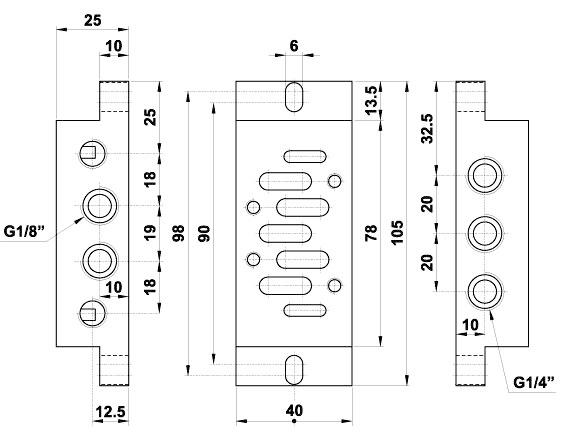
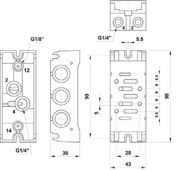
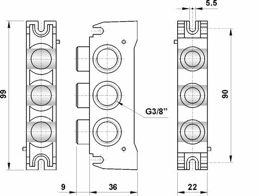
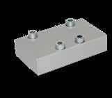
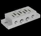
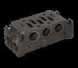
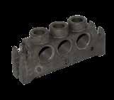
10V 13.86
FRONT TERMINAL MODULAR BASE Part No. Pack. 10V B1 0 00 00 2 Part No. Pack. 10V B3 0 00 00 1 INDIVIDUAL BASE CLOSING PLATE Part No. Pack. 10V B5 0 00 00 1 Part No. Pack. 10V B9 0 00 00 1 10V B1 0 00 00 10V B3 0 00 00 10V B5 0 00 00 10V B9 0 00 00 Page 300
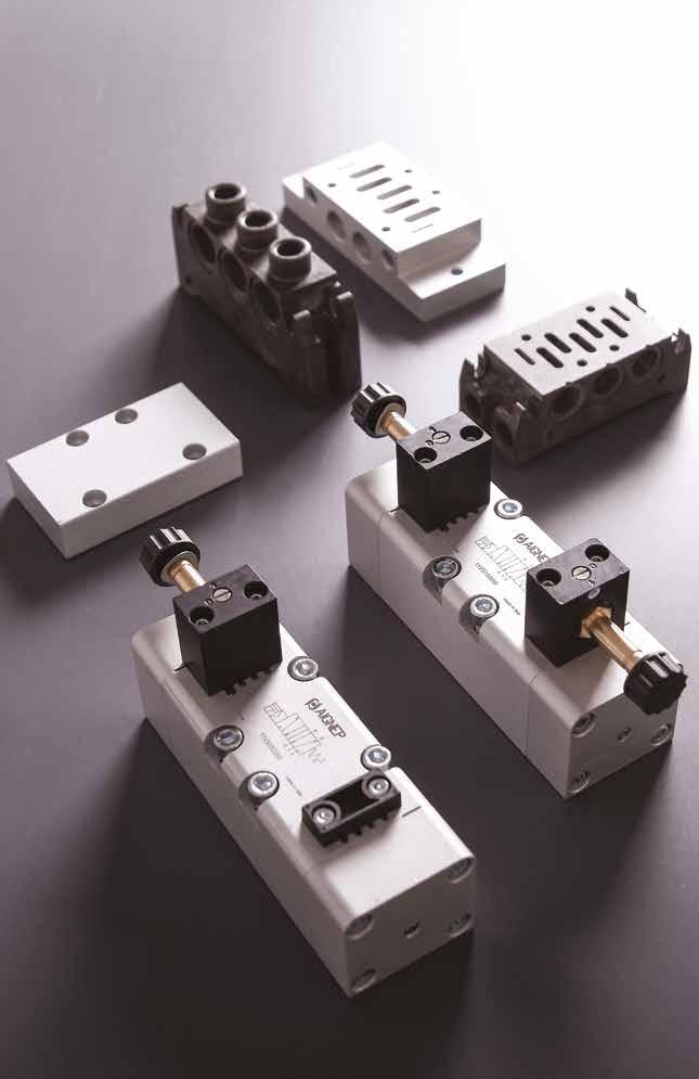
11V
Page 301
VALVES ISO 5599 - SIZE 2
TECHNICAL CHARACTERISTICS
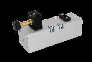
11V 13.88 6 bar FLOW RATE with ∆p 1 bar 2500 NI/min Bar OPERATING PRESSURE Monostable 2.5 ÷ 10 bar 36.2 ÷ 145 psi Bistable 1 ÷ 10 bar 14.5 ÷ 145 psi TEMPERATURE min -10 °C 14 °F max +60 °C 140 °F W MINIMUM POWER 3W - 5VA MANUAL CONTROL Two stable positions RESPONSE TIME Monostable TRA = 35 ms TRR = 60 ms Bistable TRA=TRR = 90 ms ISO 5599 SIZE 2 TRA = Response time with energised coil TRR = Response time with deenergised coil
Reference Standard 1907/2006 2011/65/CE PED 2014/68/UE Series 11V Reactuation 0 = Monostable spring return 1 = Bistable 0 Actuation S = Solenoid S 5 = 5/2 7 = 5/3 7 CC = Normally closed OC = Normally exhausted PC = Normally pressurized 00 = Function not privided Ways CC Function Component Parts and Materials • Anodised aluminium body Nickel-plated spool • NBR seals 5/2 MONOSTABLE SPRING RETURN Part No. Ways Pack. 11V S0 5 00 00 5/2 1 00 Page 302
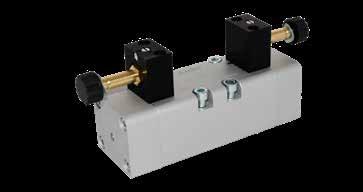
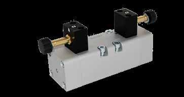
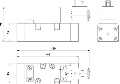
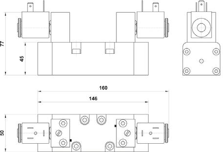
11V 13.89
POSITIONS 5/3 MONOSTABLE SPRING RETURN CC OC PC CC OC PC CC OC PC Part No. Ways Pack. 11V S1 5 00 00 5/2 1 Part No. Ways Function Pack. 11V S0 7 CC 00 5/3 CC 1 11V S0 7 OC 00 5/3 OC 1 11V S0 7 PC 00 5/3 PC 1 11V S0 5 00 00 11V S1 5 OO 00 11V S0 7 OC 00 11V S0 7 CC 00 11V S0 7 PC 00 Page 303
5/2 TWO STABLE
All the bases are supplied with screws and seals to secure the correct assembly.
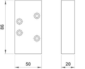
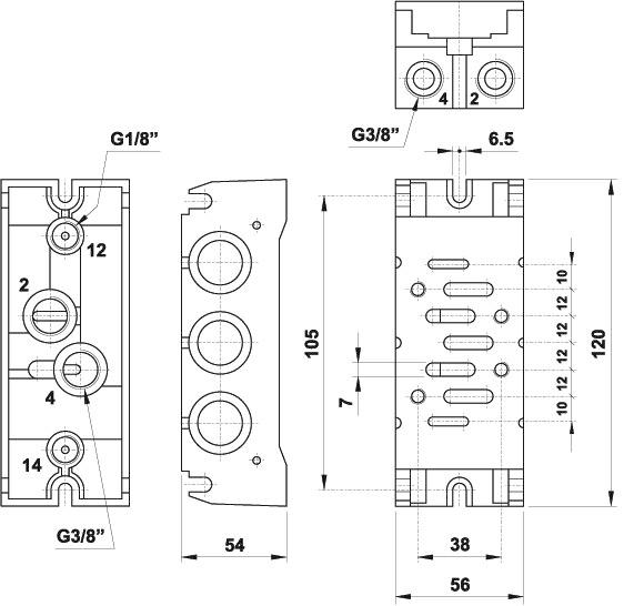
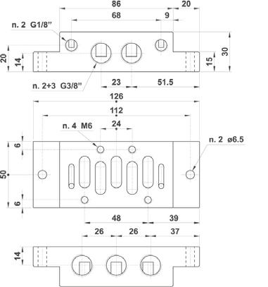
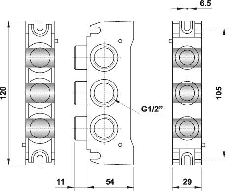
11V 13.90
FRONT TERMINAL MODULAR BASE Part No. Pack. 11V B1 0 00 00 2 Part No. Pack. 11V B3 0 00 00 1 INDIVIDUAL BASE CLOSING PLATE Part No. Pack. 11V B5 0 00 00 1 Part No. Pack. 11V B9 0 00 00 1 11V B1 0 00 00 11V B5 0 00 00 11V B3 0 00 00 11V B9 0 00 00 Page 304
Directive 2014/34/UE (ATEX)

The valves and accessories of the Series 01VP - 01VT - 01VL - 01VV - 01VN - 01VBxx - 08VP - 01VA - 01VS - 07VS - 07VB - 08VS show the following features:
II 2 GD c T6 -10°C<Tamb<60°C
II 2 GD: Device for surface installations (II = do not use device in mining) with presence of gas, vapors of powders of category 2 (equipment with high safety factor since it excludes danger of explosion, even in case of damage; it can be used in areas with possible explosive environments).
c: Devices are constructively safe
T6 – 10ºC<Tamb<60ºC: Surface temperature class and additional marking for T usage environment.
11V 13.91
See Instructions and Certificate at: WWW.AIGNEP.COM Page 305
11V 13.92 NOTES Page 306
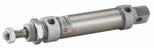
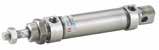
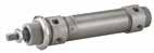

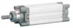

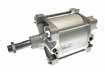

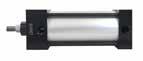
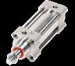
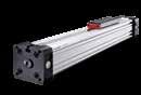
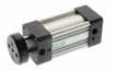


Mini Series Pg.14.13 Mini Cylinders ISO 6432 Ø 8-25 mm Mini Stainless Steel Series Pg.14.21 Mini Stainless Steel ISO 6432 Ø 16-25 mm A95 Series Pg.14.24 Limited Space Ø 32-63 mm CA - CAF Series Pg.14.11 Cartridge Cylinders Ø 6-16 mm X Series Pg.14.44 ISO 15552 Cylinders Ø 32-125 mm Q Series Pg.14.31 NFPA Series Pg.14.3 E Series Pg.14.49 ISO 6431 Cylinders Ø 32-320 mm Compact Cylinders Ø 12-100 mm NFPA Cylinders Ø 1 1/2"- 5" V Series Pg.14.51 Stainless Steel ISO 15552 Ø 32-100 mm XR Series Pg.14.95 Switches Pg.14.98 Rotary Actuators Ø 32-100 mm Magnetic Position Sensing Switches R Series Pg.14.84 Rodless Cylinders Ø 32-100 mm NHA Series Pg.14.54 Twin Rod Cylinders Ø 32-100 mm W Series Pg.14.58 Compact Cylinders Ø 20-100 mm Pg.14.66 Cylinder Accessories ISO 6431 - ISO 15552 - ISO 21287 Pg.14.75 Guided Units ISO 15552 - Ø 12-25 mm ISO 6431 VDMA - Ø 32-100 mm NFPA Series Pg.14.5 NFPA Cylinder Accessory section Ø 1 1/2"- 5" Page 307
Actuators
PNEUMATIC ACTUATORS
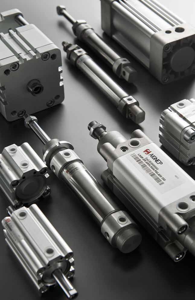
Actuators
A Page 308
NFPA CYLINDERS
TECHNICAL CHARACTERISTICS
Component Parts and Materials
1 Chrome Steel Piston Rod
2 Polyurethane Rod Seal
3 Aluminium Cap
4 O-Ring Seal
5 Polyurethane cushion seals
6 Anodized Aluminium Extrusion
7 Aluminum Cap
8 Cast Iron Bearing
9 Aluminium Piston
Piston Seal
Bar
Pressures
1 bar (0.1 MPa) / 14.5 psi
10 bar (0.7 MPa) / 145 psi
Temperatures
0 °C / 32 °F (-20 °C / -4 °F with dry air) + 80 °C / 176 °F
Media Filtered and lubricated or non-lubricated compressed air.
Functions
Double acting single or double end rod, magnetic or non-magnetic, cushioned or non-cushioned
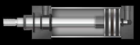
Bores
Standard Strokes from 0.5” to 10”
14.3 NFPA Series
1.5"
6"
-
Ø Stroke 1” 2” 3” 4” 5” 6” 8” 10” 1.5” 2” 2.5” 3.25” 4” 5” 6” 8” 12345 6 7 8 111213 910 Page 309
10 Nitrile
11 Magnet 12 Nitrile Piston Seal 13 Aluminum Piston
1C SN 015 A 0100 1
NFPA
DOUBLE ACTING - MAGNETIC - CUSHIONED & NON-CUSHIONED
2.5” .75”1.125”0.375”15/16”-243”.25”1.5”1”7/16”-203.75”0.625”2.5”2.188”1.25”0.625”1.875”4.75” 3.25” 1.125”1.5”0.5”3/8”-243.75”.375”1.75”1.25”3/4”-164.25”1”2.75”2.760”1.5”0.875”2.375”5.625” 4” 1.125”1.5”0.5”3/8”-244.5”.375”1.75”1.25”3/4”-164.25”1”2.75”3.32”2.063”0.875”2.375”5.625”
14.4 NFPA Series Description
Bore Size (in) A NFPA B Stainless C DoubleRod End D AirOilTank Mount Stroke Length (in) Rod End
Port PositionPort Size Cushion Position 1 3 2 4 015 1” 002 2” 025 2.5” 325 3.25” 004 4” 005 5” 006 6” 008 8” 0 NonStandard E3 HeadSquare E4 CapSquare F1 FrontFlange F2 RearFlange P1 FixedClevis P2 DetachableClevis P3 FixedEye P4 DetachableEye S1 Angle S2 SideLug S4 BottomTapped T1 HeadTrunion T2 CapTrunion T4 MidTrunionFixed SN SleeveNutwithMS4 XO NoMount X1 Head&CapExtTieRod X2 CapExtTieRod X3 HeadExtTieRod XX Special A 1/8” B 1/4” C 3/8” D 1/2” E 3/4” A None B Position1-Head&Cap C Position2-Head&Cap D Position3-Head&Cap E Position4-Head&Cap F Position1-Head G Position2-Head H Position3-Head J Position4-Head K Position1-Cap L Position2-Cap M Position3-Cap N Position4-Cap X Other 1 Standard-KK 2 Standard-CC 3 Standard-XX 6 Oversized-KK 7 Oversized-CC 8 Oversized-XX 0050 0.5” 0100 1” 0150 1.5” 0200 2” 0250 2.5” 0300 3” 0350 3.5” 0400 4” 0450 4.5” 0500 5” 1000 10” 1050 10.5” XX Other A 1/16” B 1/8” C 3/16” D 1/4” E 5/16” F 3/8” G 7/16” H 9/16” I 5/8” J 11/16” K 3/4” L 13/16” M 7/8” N 15/16”
A
+ = Add Stroke Bore ABC DD E EE GJ KK LB MM PR TN VY ZB 1.5” .75”1.125”0.375”1/4”-282”.25”1.5”1”7/16”-203.625”0.625”2.375”1.438”0.625”0.625”1.875”4.625” 2” .75”1.125”0.375”1/4”-282.5”.25”1.5”1”7/16”-203.625”0.625”2.375”1.843”0.875”0.625”1.875”4.625”
5” 1.125”1.5”0.5”1/2”-205.5”.375”1.75”1.25”3/4”-164.5”1”3”4.1”2.688”0.875”2.375”5.875” 6” 1.625”2”0.625”1/2”-206.5”.5”2”1.5”1”-145”1.375”3.25”4.875”3.25”1”2.75”6.625” 8” 1.625”2”0.625”5/8”-188.5”.75”2”1.5”1”-145.125”1.375”3.375”6.438”4.51”2.75”7.313” Page 310
SERIES NFPA ACCESSORIES
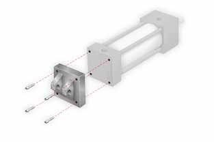

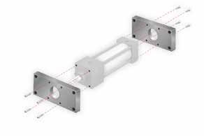
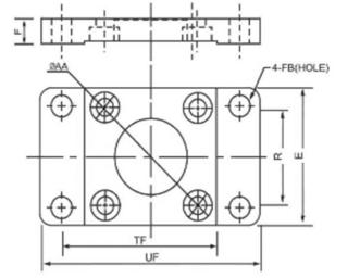
MF1 - MF2
MP1
14.5 NFPA Series
Part No. Bore Ø UF TF FB E R F AA Tapped MF12150 1.5" 33/8"23/4"5/16"2"1.43"3/8"2.02"1/4"-28 MF122202" 41/8"33/8"3/8"21/2"1.84"3/8"2.60"5/16"-24 MF122502.5" 45/8"37/8"3/8"3"2.19"3/8"3.10"5/16"-24 MF123253.25" 51/2"411/16"7/16"33/4"2.76"5/8"3.90"3/8"-24 MF124004" 61/4"57/16"7/16"41/2"3.32"5/8"4.70"3/8"-24 MF126006" 85/8"75/8"9/16"61/2"4.88"3/4"6.90"1/2"-20 Part No. Bore Ø CD FL F B C D ER G LR Tapped D-D0 MP1150 1.5" .502".75".38".76".50"2.00".62"1.43".62"1/4"-28.28" MP12002" .502".75".38".76".50"2.50".62"1.84".62"5/16"-24.34" MP12502.5" .502".75".38".76".50"3.00".62"2.19".62"5/16"-24.34" MP13253.25" .752"1.25".63"1.26".62"3.75".87"2.77".87"3/8"-24.41" MP14004" .752"1.25".63"1.26".62"4.50".87"3.32".87"3/8"-24.41" MP16006" 1.002"1.50".75"1.51".75"6.50"1.25"4.88"1.13"1/2"-20.53"
Page 311
MP2

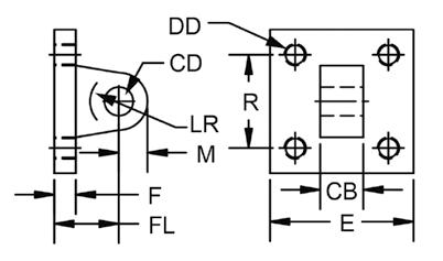
MP4
14.6 NFPA Series
Part No. Bore Ø CD FL F B C D ER G Tapped D-D0 MP2150 1.5" .502"1.13".38".76".50"2.00".62"1.43"1/4"-28.28" MP22002" .502"1.13".38".76".50"2.50".62"1.84"5/16"-24.34" MP22502.5" .502"1.13".38".76".50"3.00".62"2.19"5/16"-24.34" MP23253.25" .752"1.88".63"1.26".62"3.75".87"2.77"3/8"-24.41" MP24004" .752"1.88".63"1.26".62"4.50".87"3.32"3/8"-24.41" MP26006" 1.002"2.25".75"1.51".75"6.50"1.25"4.88"1/2"-20.53" Part No. Bore Ø CD FL F CB D ER G KK D-D0 MP4150 1.5" .502"1.13".38".75"2.00".62"1.43"1/4"-28.28" MP42002" .502"1.13".38".75"2.50".62"1.84"5/16"-24.34" MP42502.5" .502"1.13".38".75"3.00".62"2.19"5/16"-24.34" MP43253.25" .752"1.88".63"1.25"3.75".87"2.77"3/8"-24.41" MP44004" .752"1.88".63"1.25"4.50".87"3.32"3/8"-24.41" MP46006" 1.00"2.25"-1.50"6.50"-4.88"1"-14Page 312
MS1 BB
DOUBLE ACTING - MAGNETIC
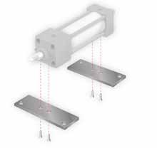
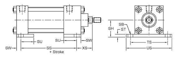
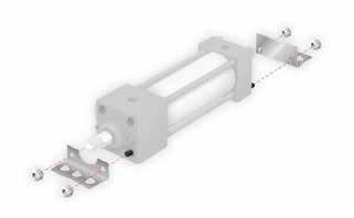
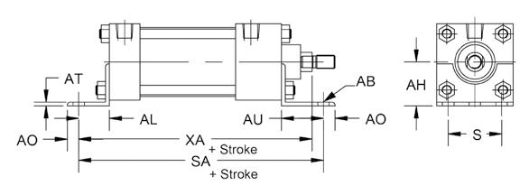
14.7 NFPA Series
Part No. Bore Ø AB AH AL AO AT AU S SA XA MS1150 1.5" .44"1.19"1.00".50".13"1.38"1.25"6.00"5.63" MS12002" .44"1.44"1.00".50".13"1.38"1.75"6.00"5.63" MS12502.5" .44"1.63"1.00".50".13"1.38"2.25"6.13"5.75" MS13253.25" .56"1.94"1.25".50".13"1.88"2.75"7.38"6.88" MS14004" .56"2.25"1.25".50".13"1.88"3.50"7.38"6.88" MS16006" .81"3.25"1.38".63".19"2.13"5.25"8.50"8.00" Part No. Bore Ø SB SH SS ST SU SW TS US XS BB150 1.5" .44"1.25"2.88".25"1.13".38"2.75"3.50"1.38" BB2002" .44"1.50"2.88".25"1.13".38"3.25"4.00"1.38" BB2502.5" .44"1.88"3.00".38"1.13".38"3.75"4.50"1.38" BB3253.25" .56"2.38"3.25".50"1.25".50"4.75"5.75"1.88" BB4004" .56"2.75"3.25".50"1.25".50"5.50"6.50"1.88" BB6006" .81"4.00"3.63".75"1.31".69"7.88"9.25"2.31" Page 313
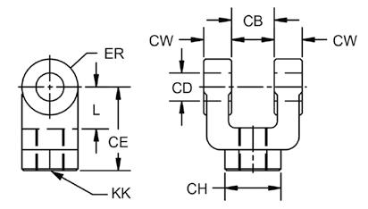
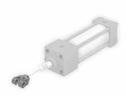
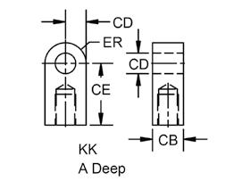
14.8 NFPA Series RC ROD CLEVIS RE ROD EYE Part No. Rod Thread L CB CD CE CH CW ER KK RC71620 7/16 - 20 .75".75".50"1.50"1.00".50".50"7/16"-20 RC3416 3/4 - 16 1.25"1.25".75"2.38"1.25".63".75"3/4"-16 RC114 1 - 14 1.50"1.50"1.00"3.13"1.50".75"1.00"1"-14 Part No. Rod Thread A L CB CD CE ER KK RE71620 7/16 - 20 .75".75".75".50"1.50".56"7/16"-20 RE3416 3/4 - 16 1.13"1.25"1.25".75"2.06".94"3/4"-16 RE114 1 - 14 1.63"1.50"1.50"1.00"2.81"1.13"1"-14 Page 314
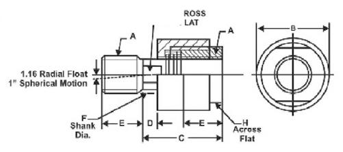
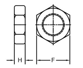
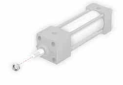
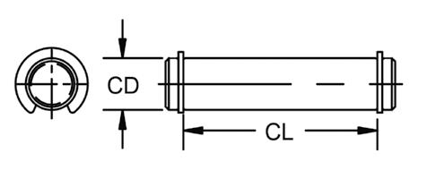
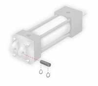
14.9 NFPA Series AC
NUT ROD JAM NUT PP PIVOT PIN Part No. Rod Thread A B C D E F G H Max Pull @ Yield AC71620 7/16 - 20 7/16"-2011/4"2"1/2"3/4"5/8"9/16"11/8"10,000 AC3416 3/4 - 16 3/4"-1613/4"25/16"5/16"11/8"31/32"7/8"11/2"34,000 AC114 1 - 14 1"-1421/2"215/16"1/2"15/8"13/8"11/4"21/4"64,000 Part No. Rod Thread H F NUT71620 7/16 - 20 .25".69" NUT3416 3/4 - 16 .42"1.13" NUT114 1 - 14 .55"1.50" Part No. Rod Thread CD CL PP50 .50" .50"1.88" PP75.75" .75"2.75" PP1001.00" 1.00"3.25" Page 315
ROD ALIGNMENT COUPLER
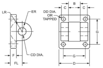
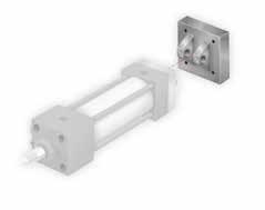
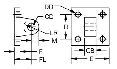
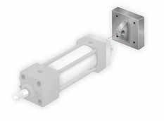
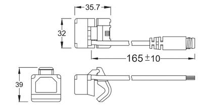
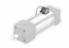
14.10 NFPA Series
EYE BRACKET
POSITION SENSING SWITCH Part No.Pin 0Fits Bore Sizes CBCD CW DD E F FL LR M R CB71620 1/2" 1-1/2" · 2" · 2-1/2" .75".50".50"3/8"-242.50".38"1.13".50".50"1.63" CB34163/4" 3-1/4" · 4" 1.25".75".63"1/2"-203.50".63"1.88"1.06".75"2.56" CB1141" 6" 1.50"1.00".75"5/8"-184.50".75"2.25"1.25"1.00"3.25" Part No.Pin 0Fits Bore Sizes CB CD DD E F FL LR M R EB50 1/2" 1-1/2" · 2" · 2-1/2" .75".50".41"2.50".38"1.13".75".50"1.63" EB753/4" 3-1/4" · 4" 1.25".75".53"3.50".63"1.88"1.25".75"2.56" EB1001" 6" 1.50"1.00".66"4.50".75"2.25"1.50"1.00"3.25" Part No. Type Switching Logic Output Operating Voltage Switching Current Power Rating Voltage Drop Shock PSRS Reed NormallyOpen-5-240VDC/AC-50/60Hz1AmpMax.30Watts3.5VMax.30G/9G PSSOURCE PNP Source NormallyOpenPNPSourcing5-30VDC1AmpMax.30Watts1.5V @ 0.5AMax50G/9G PSSINK NPN Sink NormallyOpenPNPSinking5-30VDC1AmpMax.30Watts1.5V @ 0.5AMax50G/9G Page 316
CB CLEVIS BRACKET EB
PS
CARTRIDGE CYLINDERS
TECHNICAL CHARACTERISTICS
Bar
Component Parts and Materials
1 Steel plated rod jam nut
2 Brass rod bushing
3 Steel spring
4 303 Stainless steel piston rod
5 Polyurethane rod seal
6 Nickel plated brass body
7 Zinc plated steel locking screw
Pressures
2 bar (0.2 MPa) / 29 psi
7 bar (0.7 MPa) / 101.5 psi
Temperatures
Reference
Media
Functions
Single acting threaded and non-threaded piston rod.
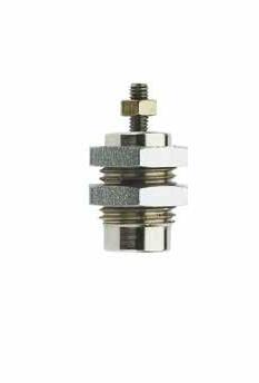
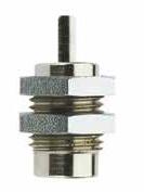
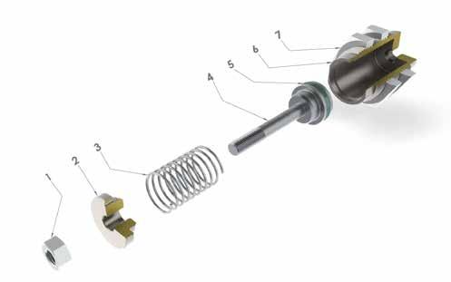
Weight Ø mm Stroke(mm) 51015
6 10g12.5g15g 10 27g32g36g 16 71g78g87g
Bores 6 - 10 - 16 mm
Standard Strokes
5 - 10 - 15 mm
14.11
Standard 1907/2006 2011/65/CE PED 2014/68/UE SILICON FREE ATEX 2014/34/UE
0 °C / 32 °F (-20 °C / -4 °F with dry air) + 80 °C / 176 °F
compressed air
Filtered and lubricated or non-lubricated
CA - CAF Series Page 317
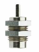
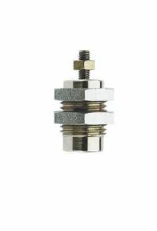
14.12 0010 0005 0010 0015 Stroke (mm) CAF Series CA Singleactingno-threadedpistonrod CAF Singleactingthreadedpistonrod 06 10 16 06 Ø (mm)
51015 6 10 16 CA SINGLE ACTING - NON-THREADED PISTON ROD
SINGLE-ACTING - THREADED PISTON ROD M D E H G B A F C CH Ø A B C D ØE F G Stroke H M CH 5 10 15 6 M10x18.5M539519.526.533.58314 10 M15x1.513M5514521.5283510.5419 16 M22x1.519M5520624.530.53713527 M D E H G B A F C CH Ø A B C D ØE F G Stroke H M CH L 5 10 15 6 M10x18.5M5M39519.526.533.583147 10 M15x1.513M5M414521.5283510.541910 16 M22x1.519M5M520624.530.5371352712 CA - CAF Series Page 318
Ø(mm)Stroke(mm)
CAF
TECHNICAL CHARACTERISTICS
Component Parts and Materials
1 Zinc plated steel rod jam nut
2 303 Stainless steel piston rod
3 Polyurethane rod seal
4 Anodized aluminum end cap
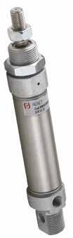
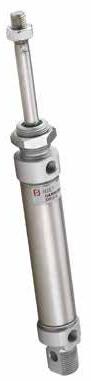
5 Zinc plated mounting nut
6 Sintered bronze rod bearing
7 NBR o-ring seals
8 Neoprene bumper 9 Brass piston 10 Polyurethane piston seal
11 Bonded ferrite magnet
12 304 Stainless steel body
Pressures
Functions
Single acting magnetic or non-magnetic. Double acting single or double end rod, magnetic or non-magnetic, cushioned or non-cushioned.
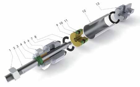
MINI CYLINDERS - ISO 6432
Standard Strokes from 10 to 320 mm
Reference Standard Mini Series Page 319
14.13
0 °C / 32 °F (-20 °C / -4 °F with dry air) + 80 °C / 176 °F
Temperatures
Media Filtered and lubricated or non-lubricated compressed air
Bores 8 - 10 - 12 - 16 - 20 - 25 mm
1 bar (0.1 MPa) / 14.5 psi 10 bar (1 MPa) / 145 psi Bar
13 Anodized aluminum end cap 1907/2006 2011/65/CE PED 2014/68/UE SILICON FREE ATEX 2014/34/UE
FORCES, SPRING LOADS AND AIR CONSUMPTION
14.14 Extend and Retract Forces Cylinder Piston rod Piston Area Operating pressure Ø Ø mm2 bar 12345678910 Output force N 8 4 Extend=50.25101520253035404550 Retract=37.736912151821242730 10 4 Extend=78.57142128354249566370 Retract=666121824303642485460 12 6 Extend=113102030405060708090100 Retract=857.5152230374552606875 16 6 Extend=2001836547290108126144162180 Retract=173163248648096112128144160 20 8 Extend=314285684112140168196224252280 Retract=26424487296120144168192216240 25 10 Extend=4904488132176220264308352396440 Retract=4123672108144180216252288324360
Spring Loads Cylinder Load spring Stroke (mm) Ø 10 25 50 Output force N 8 Loadofspringatrest4.13.52.6 Loadofcompressedspring4.54.54.5 10 Loadofspringatrest4.13.52.6 Loadofcompressedspring4.54.54.5 12 Loadofspringatrest5.54.83.5 Loadofcompressedspring666 16 Loadofspringatrest16.513.79 Loadofcompressedspring18.318.318.3 20 Loadofspringatrest1915.59.5 Loadofcompressedspring21.521.521.5 25 Loadofspringatrest272413.5 Loadofcompressedspring292929 Air Consumption Cylinder Piston Rod Piston Area Operating pressure Ø Ø mm2 bar 12345678910 Air consuption for each 10 mm of stroke Nl 8 4 Extend=50.20.0010.0020.0020.0030.0030.0040.0040.0050.0050.006 Retract=37.70.0010.0010.0020.0020.0020.0030.0030.0030.0040.004 10 4 Extend=78.50.0020.0020.0030.0040.0050.0050.0060.0070.0080.009 Retract=660.0010.0020.0030.0030.0040.0050.0050.0060.0070.007 12 6 Extend=1130.0020.0030.0050.0060.0070.0080.0090.0100.0110.012 Retract=850.0020.0030.0030.0040.0050.0060.0070.0080.0090.009 16 6 Extend=2000.0040.0060.0080.0100.0120.0140.0160.0180.0200.022 Retract=1730.0030.0050.0070.0090.0100.0120.0140.0160.0170.019 20 8 Extend=3140.0060.0090.0130.0160.0190.0220.0250.0280.0310.035 Retract=2640.0050.0080.0110.0130.0160.0180.0210.0240.0260.029 25 10 Extend=4900.0100.0150.0200.0250.0290.0340.0390.0440.0490.054 Retract=4120.0080.0120.0160.0210.0250.0290.0330.0370.0410.045 Mini Series Page 320
MB
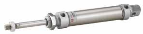
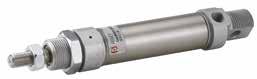
MF
0025
VS
14.15
Stroke (mm) 0010 0025 0050 0080 0100 0125 0150 0160 0200 0250 0320
Series MB Singleacting-magnetic MD Singleacting-magnetic Springextend MF Doubleacting-magnetic MFN Doubleacting-magnetic-headcut portat90º MFX Doubleacting-magnetic-headcut portonaxis MH Doubleacting-cushioned-magnetic MJ Doubleacting-magnetic withdoublerodend ML Doubleacting-cushioned-magnetic withdoublerodend Ø (mm) 008 010 012 016 020 025 0 08 Special version VS RodSealsinFKM V SealsinFKM
Ø(mm) Stroke(mm) 10 25 50 80 100 125 160 200 250 320 8 10 12 16 20 25 Intermediateorlongerstrokes areavailableuponrequest.
SINGLE ACTING - MAGNETIC
SINGLE ACTING - MAGNETIC - SPRING EXTEND L CH K F D C B A A1 P+STROKE N F R+STROKE M+STROKE G E B ØA A1 BCDEFGKLMNPR CH 8 M44M12x1.25816412M51612866466410 M44M12x1.25816412M51612866466412 M66M16x1.51219618M52216104948755 16 M66M16x1.51219618M52216109953825 20 M88M22x1.516278201/8G24201311267957 25 M10x1.2510M22x1.516308221/8G282214012681049 K+STROKE A1 L CH F D C B A P+STROKE N F R+2xSTROKE M+2xSTROKE G E B ØA A1 BCDEFGKLMNPR CH 16 M66M16x1.51219618M52216134.5978.5107.55 20 M88M22x1.516278201/8G242015412901187 25 M10x1.2510M22x1.516308221/8G282216612941309 Mini Series Page 321
MD
MF
DOUBLE ACTING - MAGNETIC
MFN
DOUBLE ACTING - MAGNETIC - HEAD CUT, PORT AT 90º
MFX
DOUBLE ACTING - MAGNETIC - HEAD CUT, PORT ON AXIS
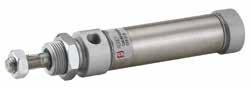
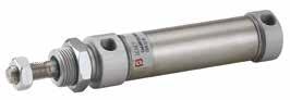
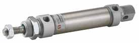
14.16
L CH K F D C B A A1 P+STROKE N F R+STROKE M+STROKE G G E B ØA A1 BCDEFGKLMNPR CH 8 M44M12x1.25816412M51612866466410 M44M12x1.25816412M51612866466412 M66M16x1.51219618M52216104948755 16 M66M16x1.51219618M52216109953825 20 M88M22x1.516278201/8G24201311267957 25 M10x1.2510M22x1.516308221/8G282214012681049 L CH K F D B A A1 P+STROKE M+STROKE G G Ø A A1 B D G K L M P CH F 16 M66M16x1.521M5221691.553518 20 M88M22x1.5271/8G2420111.56772 25 M10x1.2510M22x1.5301/8G2822118.568922 L CH K F D B A A1 P+STROKE M+STROKE G G Ø A A1 B D G K L M P CH F 16 M66M16x1.521M5221691.553518 20 M88M22x1.5271/8G2420111.56772 25 M10x1.2510M22x1.5301/8G2822118.568922 Mini Series Page 322
MH
DOUBLE ACTING - CUSHIONED - MAGNETIC
MJ
DOUBLE ACTING - MAGNETIC WITH DOUBLE ROD END
ML
DOUBLE ACTING - CUSHIONED - MAGNETIC WITH DOUBLE ROD END
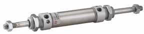
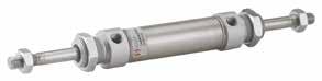
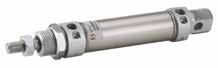
14.17
L CH K F D C B A A1 P+STROKE N F R+STROKE M+STROKE G G E B ØA A1 BCDEFGKLMNPR CH 16 M66M16x1.51221618M522161099538225 20 M88M22x1.516278201/8G24201311267957 25 M10x1.2510M22x1.516308221/8G282214012681049 K+STROKE A1 CH F B C L P+STROKE F GG K B A L Ø A A1 B C F G K L P CH 16 M66M16x1.51918M52216535 20 M88M22x1.527201/8G2420677 25 M10x1.2510M22x1.530221/8G2822689 K+STROKE A1 CH F B C L P+STROKE F GG K B A L Ø A A1 B C F G K L P CH 16 M66M16x1.52118M52216535 20 M88M22x1.527201/8G2420677 25 M10x1.2510M22x1.530221/8G2822689 Mini
Page 323
Series
PISTON ROD LOCK FOR MINI CYLINDERS - ISO 6432
How to Order
The piston rod lock can be assembled only with cylinders ISO 6432 Ø 20 or 25 mm produced with an extended piston rod.
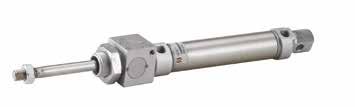
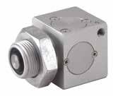
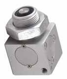
To identify the cylinder with extended piston rod and piston rod lock assembled, it is necessary to mention after the article code of the cylinder the letter “B”.
Without Pressures: LOCKED
14.18
Temperatures 0 °C / 32 °F (-20 °C / -4 °F with dry air) + 80 °C / 176 °F Media Filtered and lubricated or non-lubricated compressed air Pressures Bar
Reference Standard 1907/2006 2011/65/CE PED 2014/68/UE SILICON FREE Cylinder supply pressure Minimum release pressure 0 ÷ 7 bar (0÷0.7Mpa) 2.5 bar (0.25Mpa) 7 ÷ 10 bar (0.7÷1Mpa) 3 bar (0.3Mpa)
TECHNICAL CHARACTERISTICS
L H F E C B G D M N Part No. Ø A B C D E F G H L M N R MRL 020 20 M22x1.568.55413275M52223.5343523 MRL 025 25 M22x1.569.55413275M52224.5343526 020 Ø (mm) 020 025 MF Series B =PistonRodLockAssembled B 0025 Stroke (mm) 0010 0025 0050 0080 0100 0125 0150 0160 0200 0250 0320 Intermediateorlongerstrokes areavailableuponrequest. Mini Series Page 324
Mini

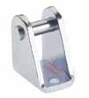
MFL
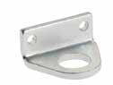
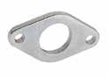
14.19
FLANGE MATERIAL: Steel
FOOT MATERIAL: Steel
CLEVIS BRACKET WITH PIN MATERIAL: Steel
MOUNTING NUT Part No. Ø A B C R S MFL 008 8-10 1233094.5 MFL 012 12-16 16440135.5 MFL 020 20-25 22550196.6 Part No. Ø A B C D G H J R S MPD 008 8-10 124.53525111616103 MPD 012 12-16 165.5423214202013.54 MPD 020 20-25 226.65440172525185 Q I S Ø D Ø G B R Z A L Ø E Ø D IS ES Code Ø ABRLZ IS ES S I Q ØEØD ØG MCC 008 8-10 12.52.5522248.1130.814184.542.3 MCC 012 12-16 1537252712180.819245.564 MCC 020 20-25 20410323016240.925306.587 Part No. A B C 0DA00 00 5I D5 ZI M12x1.25 197 0DA00 00 51 E3 ZI M16x1.5 226 0DA00 00 51 F6 ZI M22x1.5 278 MATERIAL: Steel ROD JAM NUT Part No. A B C 0DA00 00 51 B1 ZI M4 73.2 0DA00 00 51 B8 ZI M6 105 0DA00 00 51 C3 ZI M8x1.25 136.5 0DA00 00 51 C9 ZI M10x1.25 178
MPD
MCC
DA
ISO 6432 Mounting Accessories Series Page 325
ROD CLEVIS WITH LOCKABLE PIN
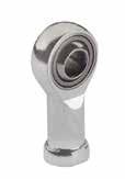
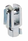
14.20 FC
MATERIAL: Steel
SPHERICAL ROD EYE MATERIAL: Steel Part No. KK A B C E F G FC 008 M4 21816844 FC 012 M6 3112241266 FC 020 M8 4216321688 FC 025 M10x1.25 522040201010 Part No. F ABC Ø Sphere DEGH LMPSW Radial load Weight Dynamic Static H700-0.13 ± 0.13 ± 0.5 ± 0.5 ± 0.7 ± 0.7 ± 0.5+0.2 -0.7 ± 0.25kgkgg TF 008 M4x0.7 57.7811.1161827361091149--TF 012 M6x1 68.9912.76.75203040910135114701.10019 TF 020 M8x1.25 810.41215.8892436481212.5165147801.90036 TF 025 M10x1.25 1012.91419.0510.52843571515196.5171.2003.10088 Mini Series Page 326
TF SELF-LUBRICATING
Bar
Mini Stainless Steel Series
STAINLESS STEEL MINI CYLINDERS - ISO 6432
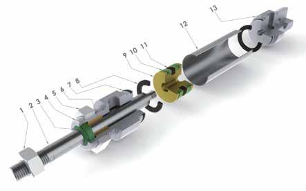
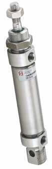
TECHNICAL CHARACTERISTICS
Reference Standard
Component Parts and Materials
1 304 Stainless steel rod jam nut
2 316 Stainless steel piston rod
3 Polyurethane rod seal
4 304 Stainless steel end cap
5 304 Stainless steel mounting nut
6 Sintered bronze rod bearing
7 NBR o-ring seals
8 Neoprene bumper
9 Brass piston
10 Polyurethane piston seal
11 Plastoferrite magnet
12 304 Stainless steel body
Pressures
2 bar (0.2 MPa) / 29 psi
10 bar (0.7 MPa) / 145 psi
Temperatures
0 °C / 32 °F (-20 °C / -4 °F with dry air) + 80 °C / 176 °F
Media Filtered and lubricated or non-lubricated compressed air.
Functions
Double-acting magnetic.
Double-acting without magnet.
Bores
16 - 20 - 25 mm
Standard Strokes from 10 to 320 mm
14.21
1907/2006 2011/65/CE PED 2014/68/UE SILICON FREE ATEX 2014/34/UE
13 304 Stainless steel end cap Page 327
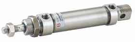
14.22 Extend and Retract Forces Cylinder Piston Rod Piston Area Operating pressure Ø Ø mm2 bar 12345678910 Output force N 16 6 Extend=2001836547290108126144162180 Retract=173163248648096112128144160 20 8 Extend=314285684112140168196224252280 Retract=26424487296120144168192216240 25 10 Extend=4904488132176220264308352396440 Retract=4123672108144180216252288324360 Cylinder Piston Rod Piston Area Operating pressure Ø Ø mm2 bar 12345678910 Air consuption for each 10 mm of stroke Nl 16 6 Extend=2000.0040.0060.0080.0100.0120.0140.0160.0180.0200.022 Retract=1730.0030.0050.0070.0090.0100.0120.0140.0160.0170.019 20 8 Extend=3140.0060.0090.0130.0160.0190.0220.0250.0280.0310.035 Retract=2640.0050.0080.0110.0130.0160.0180.0210.0240.0260.029 25 10 Extend=4900.0100.0150.0200.0250.0290.0340.0390.0440.0490.054 Retract=4120.0080.0120.0160.0210.0250.0290.0330.0370.0410.045 Air Consumption MFI DOUBLE ACTING - MAGNETIC L CH K F D C B A A1 P+STROKE N F R+STROKE M+STROKE G G E B ØA A1 BCDEFGKLMNPR CH 16 M66M16x1.51219618M52216109953825 20 M88M22x1.516278201/8G24201311267957 25 M10x1.2510M22x1.516308221/8G282214012681049
Stroke (mm) 0010 0025 0050 0080 0100 0125 0150 0160 0200 0250 0320 Series MFI Doubleacting-magnetic Ø (mm) 016 020 025 0 16 Special version VS RodSealsinFKM V SealsinFKM
Ø(mm) Stroke(mm) 10 25 50 80 100 125 160 200 250 320 16 20 25 Intermediateorlongerstrokesareavailableuponrequest.
Page 328
0025
VS MFI
Mini Stainless Steel Series
MFLI
14.23
FLANGE
Steel
FOOT MATERIAL:
Steel
CLEVIS BRACKET WITH PIN MATERIAL:
Steel DA MOUNTING NUTS MATERIAL: Stainless Steel Part No. Ø A B C R S MFLI 016 16 16440135.5 MFLI 020 20-25 22550196.6 Part No. Ø A B C D G H J R S MPDI 016 16 165.5423214202013.54 MPDI 020 20-25 226.65443172525185 Q I S Ø D Ø G B R Z A L Ø E Ø D IS ES Code Ø ABRLZ IS ES S I Q ØEØD ØG MCCI 012 16 1537252712180.819245.564 MCCI 020 20-25 20410323016240.925306.587 Part No. A B C 0DA00 00 43 E3 00 M16x1.5 226 0DA00 00 43 F6 00 M22x1.5 278 ISO 6432 Stainless Steel Mounting Accessories ROD JAM NUT Part No. A B C 0DA00 00 43 B8 00 M6 105 0DA00 00 43 C3 00 M8x1.25 136.5 0DA00 00 43 C9 00 M10x1.25 178 Mini Stainless Steel Series Page 329
MATERIAL: Stainless
MPDI
Stainless
MCCI
Stainless
Bar
TECHNICAL CHARACTERISTICS
SERIES A95 - LIMITED SPACE CYLINDERS
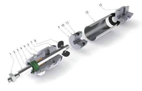
Reference Standard
Component Parts and Materials
1 Zinc plated steel rod jam nut
2 Chrome plated steel piston rod
3 Polyurethane rod seal
4 Anodized aluminum end cap
5 Zinc plated mounting nut
6 Sintered bronze rod bearing
7 NBR o-ring seals
8 Neoprene bumper
9 Anodized aluminum piston
10 Polyurethane piston seal
11 Bonded ferrite magnet
12 304 Stainless steel body
13 Anodized aluminum end cap
Pressures
1 bar (0.1 MPa) / 14.5 psi
10 bar (1 MPa) / 145 psi
Temperatures
0 °C / 32 °F (-20 °C / -4 °F with dry air) + 80 °C / 176 °F
Media
Filtered and lubricated or non-lubricated compressed air.
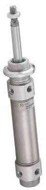
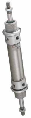
Functions
Single acting magnetic or non-magnetic.
Double acting single or double rod end, magnetic or non-magnetic, cushioned or non-cushioned.
Bores
32 - 40 - 50 - 63 mm
Standard Strokes from 10 to 500 mm
14.24
1907/2006 2011/65/CE PED 2014/68/UE SILICON FREE ATEX 2014/34/UE A95 Series Page 330
FORCES, SPRING LOADS AND AIR CONSUMPTION
14.25 Spring Loads Cylinder Load spring Stroke (mm) Ø 10 25 50 Output force N 32 Loadofspringatrest565142 Loadofcompressedspring606060 40 Loadofspringatrest605544 Loadofcompressedspring656565 50 Loadofspringatrest645746 Loadofcompressedspring686868 63 Loadofspringatrest655847 Loadofcompressedspring707070 Extend and Retract Forces Cylinder Piston Rod Piston Area Operating pressure Ø Ø mm2 bar 12345678910 Output force N 32 12 Extend=80472144216288360432504576648720 Retract=69162124186248310372434496558620 40 16 Extend=12571102203304405506607708809901100 Retract=105695190285380475570665760855950 50 20 Extend=196317535052570087510501225140015751750 Retract=16491482964445927408881036118413321480 63 20 Extend=31172805608401120140016801960224025202800 Retract=28032505007501000125015001750200022502500 Cylinder Piston Rod Piston Area Operating pressure Ø Ø mm2 bar 12345678910 Air consuption for each 10 mm of stroke Nl 32 12 Extend=8040.0160.0240.0320.0400.0480.0560.0640.0720.0800.088 Retract=6910.0140.0210.0280.0350.0410.0480.0550.0620.0690.076 40 16 Extend=12570.0250.0380.0500.0630.0750.0880.1010.1130.1260.138 Retract=10560.0210.0320.0420.0530.0630.0740.0840.0950.1060.116 50 20 Extend=19630.0390.0590.0790.0980.1180.1370.1570.1770.1960.216 Retract=16490.0330.0490.0660.0820.0990.1150.1320.1480.1650.181 63 20 Extend=31170.0620.0940.1250.1560.1870.2180.2490.2810.3120.343 Retract=28030.0560.0840.1120.1400.1680.1960.2240.2520.2800.308 Air Consumption
A95 Series Page 331
AB Singleacting-magnetic
AD Singleacting-magnetic-springextend
AF Doubleacting-magnetic
AH Doubleacting-cushioned-magnetic
AJ Doubleacting-magneticwithdoublerodend
AL Doubleacting-cushioned-magnetic withdoublerodendIntermediateorlongerstrokes areavailableuponrequest.
14.26 Ø(mm) Stroke(mm) 10 25 50 80 100 125 160 200 250 320 400 500 32 40 50 63 0025 Stroke (mm) 0010 0025 0050 0080 0100 0125 0150 0160 0200 0250 0320 0400 0500 Series Ø (mm) 032 040 050 063 0 32 AB
A95 Series Page 332
AB
SINGLE ACTING - MAGNETIC
AD
SINGLE ACTING - MAGNETIC - SPRING EXTEND
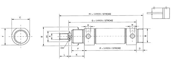
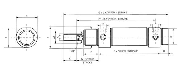
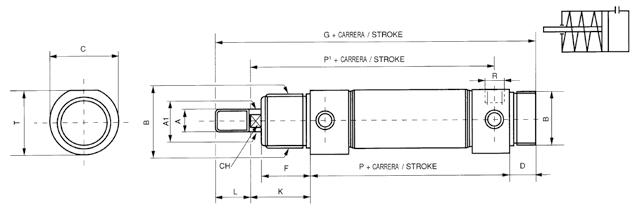
AF
DOUBLE ACTING - MAGNETIC
14.27
G+ P1+ P+ Ø A A1 B T C D F G K L PP1 CH R 32 M10x1.2512M30x1.536.5381430168382096125101/8”GAS 40 M12x1.2516M38x1.5444616351964524111144121/4”GAS 50 M16x1.520M45x1.5555718382205032120158161/4”GAS 63 M16x1.520M45x1.567.57018382245032124161163/8”GAS STROKE STROKE STROKE HUB COURSE Ø A A1 B T C D F G K L PP1 CH R 32 M10x1.2512M30x1.536.5381430168382096125101/8”GAS 40 M12x1.2516M38x1.5444616351964524111144121/4”GAS 50 M16x1.520M45x1.5555718382205032120158161/4”GAS 63 M16x1.520M45x1.567.57018382245032124161163/8”GAS STROKE STROKE STROKE Ø A A1 B T C D F G K L PP1 CH R 32 M10x1.2512M30x1.536.5381430134382096168101/8”GAS 40 M12x1.2516M38x1.5444616351564524111196121/4”GAS 50 M16x1.520M45x1.5555718381705032120220161/4”GAS 63 M16x1.520M45x1.567.57018381745032124224163/8”GAS A95 Series Page 333
AH
DOUBLE ACTING - CUSHIONED - MAGNETIC
AJ AL
DOUBLE ACTING - CUSHIONED - MAGNETIC WITH DOUBLE ROD END
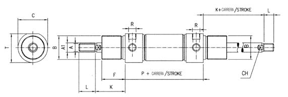
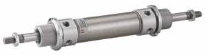
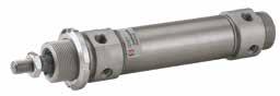
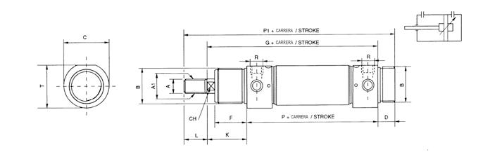
14.28
STROKE STROKE STROKE Ø A A1 B T CDFGK L PP1 CH R 32 M10x1.2512M30x1.536.5381430134382096168101/8”GAS 40 M12x1.2516M38x1.5444616351564524111196121/4”GAS 50 M16x1.520M45x1.5555718381705032120220161/4”GAS 63 M16x1.520M45x1.567.57018381745032124224163/8”GAS STROKE STROKE Ø A A1 B T C F K L P CH R 32 M10x1.2512M30x1.536.53830382096101/8"GAS 40 M12x1.2516M38x1.54446354524111121/4"GAS 50 M16x1.520M45x1.55557385032120161/4"GAS 63 M16x1.520M45x1.567.570385032124163/8"GAS STROKE STROKE Ø A A1 B T C F K L P CH R 32 M10x1.2512M30x1.536.53830382096101/8"GAS 40 M12x1.2516M38x1.54446354524111121/4"GAS 50 M16x1.520M45x1.55557385032120161/4"GAS 63 M16x1.520M45x1.567.570385032124163/8"GAS A95 Series Page 334
A95 Cylinder Mounting Accessories
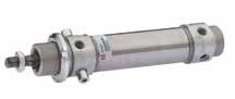

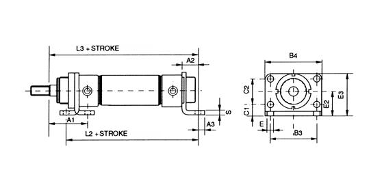
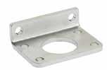
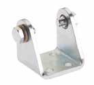
ACC
CLEVIS BRACKET WITH PINS
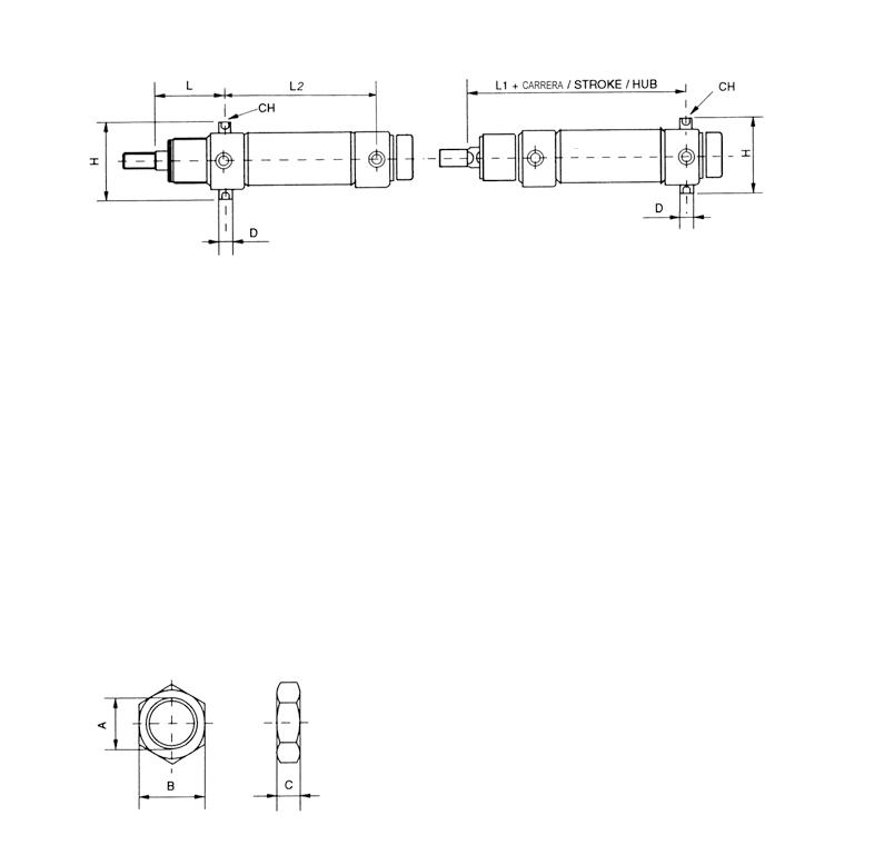
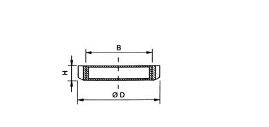
APE
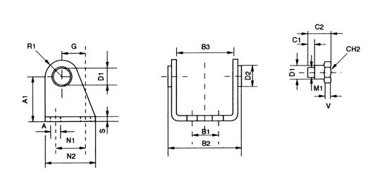
14.29
MATERIAL: Steel
FOOT FLANGE MATERIAL: Steel
MOUNTING NUT MATERIAL: Steel
APD
AGT
HEAD TRUNNION MATERIAL: Steel Part No. Ø D1 D2 A A1 G M1 N1 N2 R1 S CH2 B1 B2B3 V C1 C2 ACC 032 32 101673520M8x12440124132050.138.14618 ACC 040 40 121894027M10x13050135172860.146.15721.6 ACC 050 50 142394530M12x1.53454146193674.157.16926.4 ACC 063 63 162495034M14x1.53565166194288.170.161534 Part No. ØE E2 E3 C1 C2 L2 L3 B3 B4 S A1 A2 A3 APD 032 32 7284914281241485266448147 APD 040 40 93358183015117660805602010 APD 050 50 94070204016019070906642010 APD 063 63 94580205016419476966652010 Part No. B D H AGT 032 M30x1.5 457 AGT 040 M38x1.5 508 AGT 050 M45x1.5 589 STROKE Part No. Ø D H L1 L2 L CH APE 032 32 105112578475 APE 040 40 126114487576 APE 050 50 147515896626 APE 063 63 169016198638
A95 Series Page 335
DA
ROD JAM NUT
MATERIAL: Steel
ROD CLEVIS WITH LOCKABLE PIN
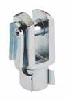
MATERIAL: Steel
SELF-LUBRICATING SPHERICAL ROD EYE
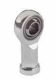
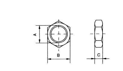
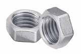
14.30
FC
TF
Part No. A B C 0DA00 00 51 C9 ZI M10x1.25 178 0DA00 00 51 D5 ZI M12x1.25 197 0DA00 00 51 E3 ZI M16x1.5 226 Part No. KK A B C E F G FC 025 M10x1.25 522040201010 FC 040 M12x1.25 622448241212 FC 050 M16x1.5 833264321616 Part No. F ABC Ø Sphere DEGH LMPSW Radial load Weight Dynamic Static H700-0.13 ± 0.13 ± 0.5 ± 0.5 ± 0.7 ± 0.7 ± 0.5+0.2 -0.7 ± 0.25kgkgg TF 025 M10x1.25 1012.91419.0511.53043581515196.5161.2003.10088 TF 040 M12x1.25 1215.41622.2312.53450671817.5226.5181.4003.700120 TF 050 M16x1.5 1619.32128.5815.54264852422278242.5006.300240 A95 Series Page 336
MATERIAL: Steel
Bar
SERIES Q - COMPACT CYLINDERS
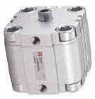
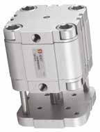
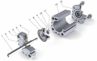
TECHNICAL CHARACTERISTICS
Reference Standard
Component Parts and Materials
1 303 Stainless steel piston rod (ø12-25) Chrome plated steel piston rod (ø32-100)
2 Anodized aluminum end cap
3 Zinc plated steel screw
4 Polyurethane rod seal
5 Sintered bronze rod bearing
6 NBR o-ring seals
7 Polyurethane piston seal
8 Bonded ferrite magnet
9 Aluminum piston
10 NBR o-ring seals
11 Zinc plated steel piston nut
12 Anodized aluminum body
13 Anodized aluminum end cap
Pressures
1 bar (0.1 MPa) / 14.5 psi
10 bar (0.7 MPa) / 145 psi
Temperatures
0 °C / 32 °F (-20 °C / -4 °F with dry air) + 80 °C / 176 °F
Media
Filtered and lubricated or non-lubricated compressed air.
Functions
Single acting magnetic.
Double-acting magnetic.
Single or through piston rod magnetic. Antirotation magnetic.
Bores from 12 to 100 mm
Standard Strokes from 5 to 200 mm
14.31
1907/2006 2011/65/CE PED 2014/68/UE SILICON FREE ATEX 2014/34/UE Q Series Page 337
14.32 Cylinder Piston Rod Piston Area Operating pressure Ø Ø mm2 bar 12345678910 Output force N 126 Extend=113102030405060708090100 Retract=857.5152230374552606875 168 Extend=2001835537090105125145160180 Retract=15013264053658095105120130 2010 Extend=314285585110140170195220250280 Retract=23521426085105125150170190210 2510 Extend=4904488132176220264308352396440 Retract=4123672108144180216252288324360 3212 Extend=80472144216288360432504576648720 Retract=69162124186248310372434496558620 4012 Extend=12571102203304405506607708809901100 Retract=11441002003004005006007008009001000 5016 Extend=196317535052570087510501225140015751750 Retract=17621553104656207759301085124013951550 6316 Extend=31172805608401120140016801960224025202800 Retract=29162605207801040130015601820208023402600 8020 Extend=502745090013501800225027003150360040504500 Retract=471242084012601680210025202940336037804200 10025 Extend=7854700140021002800350042004900565063607000 Retract=7363660132019802640330039604620528059406600 Extend and Retract Forces Ø (mm) 012 016 020 025 032 040 050 063 080 100 Series QB Singleacting-magnetic QD Singleacting-magnetic-springextend QF Doubleacting-magnetic QJ Doubleacting-magnetic withdoublerodend QFA Doubleacting-magnetic-antirotation Version =Standardfemalerod M =Malerod(NOQFA) Stroke (mm)
0005 0010 0015 0020 0025 0030 0040 0050 0060 0080 0100 0125 0150 0200 Intermediateorlongerstrokes areavailableuponrequest. Ø(mm) Stroke(mm) 5 10 15 20 2530 40 50 60 80 100 125 150 200 12 16 20 25 32 40 50 63 80 100
Q Series Page 338
QF 0 12 0025
FORCES, SPRING LOADS AND AIR CONSUMPTION
14.33 Air Consumption Cylinder Piston Rod Piston Area Operating pressure Ø Ø mm2 bar 12345678910 Air consuption for each 10 mm of stroke Nl 12 6 Extend=1130.0020.0030.0050.0060.0070.0080.0090.0100.0110.012 Retract=850.0020.0030.0030.0040.0050.0060.0070.0080.0090.009 16 8 Extend=2000.0040.0060.0080.0100.0120.0140.0160.0180.0200.022 Retract=1500.0030.0050.0060.0080.0090.0110.0120.0140.0150.017 20 10 Extend=3140.0060.0090.0130.0160.0190.0220.0250.0280.0310.035 Retract=2350.0050.0070.0090.0120.0140.0160.0190.0210.0240.026 25 10 Extend=4900.0100.0150.0200.0250.0290.0340.0390.0440.0490.054 Retract=4120.0080.0120.0160.0210.0250.0290.0330.0370.0410.045 32 12 Extend=8040.0160.0240.0320.0400.0480.0560.0640.0720.0800.088 Retract=6910.0140.0210.0280.0350.0410.0480.0550.0620.0690.076 40 12 Extend=12570.0250.0380.0500.0630.0750.0880.1010.1130.1260.138 Retract=11440.0230.0340.0460.0570.0690.0800.0920.1030.1140.126 50 16 Extend=19630.0390.0590.0790.0980.1180.1370.1570.1770.1960.216 Retract=17620.0350.0530.0700.0880.1060.1230.1410.1590.1760.194 63 16 Extend=31170.0620.0940.1250.1560.1870.2180.2490.2810.3120.343 Retract=29160.0580.0870.1170.1460.1750.2040.2330.2620.2920.321 80 20 Extend=50270.1010.1510.2010.2510.3020.3520.4020.4520.5030.553 Retract=47120.0940.1410.1880.2360.2830.3300.3770.4240.4710.518 100 25 Extend=78540.1570.2360.3140.3930.4710.5500.6280.7070.7850.864 Retract=73630.1470.2210.2950.3680.4420.5150.5890.6630.7360.810 Spring Loads Cylinder Load spring Stroke (mm) Ø 5 10 15 20 25 Output force N 12 Loadofspringatrest7.56.8 Loadofcompressedspring88 16 Loadofspringatrest12.310.89.57.86.5 Loadofcompressedspring13.313.313.313.313.3 20 Loadofspringatrest15.71412.210.48.7 Loadofcompressedspring17.417.417.417.417.4 25 Loadofspringatrest19.518.517.31615 Loadofcompressedspring2222222222 32 Loadofspringatrest27.825.322.820.217.7 Loadofcompressedspring3030303030 40 Loadofspringatrest36.43431.729.527 Loadofcompressedspring3636363636 50 Loadofspringatrest3230.52927.826.5 Loadofcompressedspring3535353535 63 Loadofspringatrest6158.556.353.551.5 Loadofcompressedspring64.864.864.864.864.8 80 Loadofspringatrest91.388858278.7 Loadofcompressedspring9494949494 100 Loadofspringatrest150145140134129 Loadofcompressedspring156156156156156 Q Series Page 339

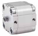
14.34 QB SINGLE ACTING - MAGNETIC Ø 12-16-20-25 Ø 32-40-50-63-80-100 L2 L E CH L1 E1 E L L L1 E E1 L2 L H2 H+ N1+ T2 T D2 M2 N CH T1 D1 H1+ T3 E KK A + = Add Stroke Ø KK AT T1 T2 D1 L E1 M3 T3 M2 H H2 D2 N N1 L2 E L1 H1 CH 12 M616641.5629M5M416M3357.566.528.53018142.55 16 M820842629M5M416M4358.586.528.53018143.57 20 M10X1,2522842636M5M518.5M53971083137.5221.5469 25 M10X1,2522842640M5M518.5M53971083141.5261.5469 32 M10X1,25221042.8650G1/8M621.5M6427126.535.5523224910 40 M10X1,25221042.8660G1/8M621.5M645.58.5127.53862.5422.55410 50 M12X1,25241243.5668G1/8M823.5M845.510167.5387150355.513 63 M12X1,25241243.5887G1/8M1028.5M85110.5167.543.59162461.513 80 M16X1,5321644.58107G1/8M1028.5M106212209.552.51118247517 100 M20X1,54020468128G1/4M1028.5M126815.52510.557.5133103583.522 Q Series Page 340
SINGLE ACTING - MAGNETIC - SPRING EXTEND
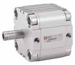
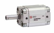
14.35
QD
D2 L L1 E E1 L2 L H2+ H+ N1+ T2 T M2 N E CH T1 D1 H1++ T3 M3 CH L L1 E E1 L2 L E KK A + =
Stroke
= Double stroke dimension and add it Ø KK AT T1 T2 D1 L E1 M3 T3 M2 H H2 D2 N N1 L2 E L1 H1 CH 12 M616641.5629M5M416M3357.566.528.53018142.55 16 M820842629M5M416M4358.586.528.53018143.57 20 M10X1,2522842636M5M518.5M53971083137.5221.5469 25 M10X1,2522842640M5M518.5M53971083141.5261.5469 32 M10X1,25221042.8650G1/8M621.5M6427126.535.5523224910 40 M10X1,25221042.8660G1/8M621.5M645.58.5127.53862.5422.55410 50 M12X1,25241243.5668G1/8M823.5M845.510167.5387150355.513 63 M12X1,25241243.5887G1/8M1028.5M85110.5167.543.59162461.513 80 M16X1,5321644.58107G1/8M1028.5M106212209.552.51118247517 100 M20X1,54020468128G1/4M1028.5M126815.52510.557.5133103583.522 Q Series Page 341
Ø 12-16-20-25 Ø 32-40-50-63-80-100
Add
++
14.36
Ø 12-16-20-25 Ø 32-40-50-63-80-100 L2 L E CH L1 E1 E L L L1 E E1 L2 L H2 H+ N1+ T2 T D2 M2 N CH T1 D1 H1+ T3 E KK A + = Add Stroke Ø KK AT T1 T2 D1 L E1 M3 T3 M2 H H2 D2 N N1 L2 E L1 H1 CH 12 M616641.5629M5M416M3357.566.528.53018142.55 16 M820842629M5M416M4358.586.528.53018143.57 20 M10X1,2522842636M5M518.5M53971083137.5221.5469 25 M10X1,2522842640M5M518.5M53971083141.5261.5469 32 M10X1,25221042.8650G1/8M621.5M6427126.535.5523224910 40 M10X1,25221042.8660G1/8M621.5M645.58.5127.53862.5422.55410 50 M12X1,25241243.5668G1/8M823.5M845.510167.5387150355.513 63 M12X1,25241243.5887G1/8M1028.5M85110.5167.543.59162461.513 80 M16X1,5321644.58107G1/8M1028.5M106212209.552.51118247517 100 M20X1,54020468128G1/4M1028.5M126815.52510.557.5133103583.522 Q Series Page 342
QF DOUBLE ACTING - MAGNETIC
SINGLE ACTING - MAGNETIC WITH DOUBLE ROD END

14.37
QJ
Ø 12-16-20-25 Ø 32-40-50-63-80-100 CH D2 L L1 E E1 H2+ L2 L H2 H+ N1+ T2 N T M2 E M3 H1+ T3 H3++ L L1 E E1 L2 L E CH KK A KK A + = Add Stroke ++ = Double stroke dimension and add it Ø KK AT M2 T2 D2 L E1 M3 T3 CH H H2 H3 N N1 L2 E L1 H1 12 M6166M31.5629M5M4165357.5506.528.53018142.5 16 M8208M42829M5M4167358.5526.528.53018143.5 20 M10X1,25228M521036M5M518.593975383137.5221.546 25 M10X1,25228M521040M5M518.593975383141.5261.546 32 M10X1,252210M62.81250G1/8M621.510427566.535.55232249 40 M10X1,252210M62.81260G1/8M621.51045.58.562.57.53862.5422.554 50 M12X1,252412M83.51668G1/8M823.51345.51065.57.5387150355.5 63 M12X1,252412M83.51687G1/8M1028.5135110.5727.543.59162461.5 80 M16X1,53216M104.520107G1/8M1028.5176212869.552.511182475 100 M20X1,54020M12625128G1/4M1028.5226815.59910.557.5133103583.5 Q Series Page 343
QFA
DOUBLE ACTING - MAGNETIC - ANTI ROTATION
14.38
TL L1 H4+ N1+ H+ D1 F1 H2 N F T1 H1+ D T3 M3 D2 A B C L2 L E L E TL L2 L E TL E L TL + = Add Stroke ØABCD D1 D2 EF F1 H H1 H2 H4 L L1 L2 M3 N N1 T1 T3 TL 12 M363.546618M333542.57.547.529530M46.528.54169.9 16 M363.546818M333543.58.548.529530M46.528.54169.9 20 M363.5661022M44394675436837.5M5831418.512 25 M484.5661026M55394675440841.5M5831418.515.6 32 M485.5661232M554249759501052M66.535.5421.519.8 40 M485.5661242M5545.5548.764601062.5M67.538421.523.3 50 M6117861650M6645.555.510.267.5681271M87.538423.529.7 63 M6117881662M665161.510.573.5871291M107.543.5428.535.4 80 M81491282082M886275128910714111M109.552.5428.546 100 M814912825103M10106883.515.597.512814133M1010.557.5428.556.6 Q Series Page 344
Ø 12-16-20-25 Ø 32-40-50-63-80-100
QFL
QCP
14.39
FLANGE Ø 12-25 MATERIAL: Steel QFL FLANGE Ø 32-100 MATERIAL: Steel
LOW-RISE PEDESTAL Ø 12-32 MATERIAL: Steel Part No. Ø A B C D E F G H I L M QFL 012 12 - 16 18435518294.595.5105.410 QFL 020 20 22557022365.5106.6105.412 QFL 025 25 26607626405.5106.6105.412 Part No. Ø A B C D E F G H I L M N QFL 032 32 32658032506.6117106.41432 QFL 040 40 428210242606.6119106.41436 QFL 050 50 509011050689159128.61845 QFL 063 63 621101306287111591510.61850 QFL 080 80 82135160821071118121510.62363 QFL 100 100 1031631901031281118141510.62875 Part No. Ø CBDEFGH I STRUZ QCP 012 12 - 16 18183017.517.54.41313315925.5 QCP 020 20 22223622225.416164171026.6 QCP 025 25 26264022235.417164191126.6 QCP 032 32 32325026246.616185201226.6
Q Series Page 345
SERIES Q Mounting Accessories
QPC
LOW-RISE PEDESTAL
Ø 40-100
MATERIAL: Steel
QCM
EYE BRACKET WITH SELF-LUBRICATING BUSHINGS MATERIAL: Aluminium
QCF
CLEVIS BRACKET WITH SELF-LUBRICATING BUSHINGS
MATERIAL: Aluminium
14.40
Part No. Ø C B D E F G H I S U Z QCP 040 40 4242602829.56.621.520559 QCP 050 50 505068323092224659 QCP 063 63 6262843939928.5276511 QCP 080 80 828210236.536.51124.5308511 QCP 100 100 10310312338.538.51126.5338513.5 Part No. Ø ABCDEFGHILMNOPQ QCM 012 12 - 16 1827104.52.6616264.51081236 QCM 020 20 22341152.6620285.512101638 QCM 025 25 26381152.6620285.512101638 Part No. Ø ABCDEFGHILMNOPQ QCF 032 32 324813.55.55.59222.5106.61412264510 QCF 040 40 425813.55.55.59252.512.56.61414285212 QCF 050 50 506615.57.56.511272.512.591814326012 QCF 063 63 6283187.56.51132415111818407016 QCF 080 80 82102199101336415112318509016 QCF 100 100 1031231991015414201128236011020 Q Series Page 346
VAS
MATERIAL: Aluminium
MATERIAL: Stainless Steel
VPE
PIN WITH RETAINER CLIPS
MATERIAL: Steel MATERIAL: Stainless Steel
SPHERICAL ROD EYE WITH MALE THREAD
MATERIAL: Steel
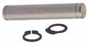
14.41
EYE BRACKET
TM
Ø D BI BG BH BM BN BO BQ ØBR ØQ Part No. Part No. Ø Q BG BH BI BM BN BO BQ BR VAS 032 VASI 032 32 6.61831213238512620 VAS 040VASI 040 40 6.62235243641542822 VAS 050VASI 050 50 93045334550653226 VAS 063VASI 063 63 93550375052674030 VAS 080VASI 080 80 114060476366865030 VAS 100VASI 100 100 115070557176966038 Part No. Part No. Ø G BT BU CG CH VPE 032 VPEI 032 32 1046539.61.1 VPE 040VPEI 040 40 12536011.51.1 VPE 050VPEI 050 50 12616811.51.1 VPE 063VPEI 063 63 16717815.21.1 VPE 080VPEI 080 80 16919815.21.1 VPE 100VPEI 100 100 20111118191.3 Part No. F A B C Ø Sphere D E GH L Radial load Weight Dynamic Static TM 020 M5x0.8 57.5811.117.518334219430100013 TM 032 M6x1 68.9912.77.520364621470110015 TM 050 M8x1.25 810.41215.889.524425425780190034 TM 080 M10x1.5 1012.91419.0511.5304863281200310070 TM 100 M12x1.75 1215.41622.2312.53454713214003700110 Q Series Page 347
FORCES, SPRING LOADS AND AIR CONSUMPTION
14.42 Extend and Retract Forces Compatible for Series X - E - V - N Cylinder Piston Rod Piston Area Operating pressure Ø Ø mm2 bar 12345678910 Output force N 32 12 Extend=80472144216288360432504576648720 Retract=69162124186248310372434496558620 40 16 Extend=12571102203304405506607708809901100 Retract=105695190285380475570665760855950 50 20 Extend=196317535052570087510501225140015751750 Retract=16491482964445927408881036118413321480 63 20 Extend=31172805608401120140016801960224025202800 Retract=28032505007501000125015001750200022502500 80 25 Extend=502745090013501800225027003150360040504500 Retract=453640581012151620202524302835324036454050 100 25 Extend=7854700140021002800350042004900565063607000 Retract=7363660132019802640330039604620528059406600 125 32 Extend=1227011042208331244165520662477288832993611040 Retract=1146810322064309641285160619272248256928810320 160 40 Extend=20096177435485322709788711064512419141941596817742 Retract=1884016633326499066538316998011643133071497016633 200 40 Extend=3144027725544831611089138611663319406221782495027723 Retract=3014426615322798410645133071596818629212912395226614 250 50 Extend=48750433186631299517326216582599030322346533898543317 Retract=46800415883161247516663207922495029109332673742641584 320 63 Extend=788727097141942129128388354854258249679567766387370971 Retract=767766822136442046627288341104093247754545766139868220 Cylinder Load spring Stroke (mm) Ø 25 50 75 80 100 Output force N 32 Loadofspringatrest50413331.524.5 Loadofcompressedspring5858585858 40 Loadofspringatrest5243343225 Loadofcompressedspring6161616161 50 Loadofspringatrest9277646049 Loadofcompressedspring110110110110110 63 Loadofspringatrest9277646049 Loadofcompressedspring110110110110110 80 Loadofspringatrest11798797559 Loadofcompressedspring138138138138138 100 Loadofspringatrest11798797559 Loadofcompressedspring138138138138138 Spring Loads
Page 348
14.43 Air Consumption Cylinder Piston Rod Piston Area Operating pressure Ø Ø mm2 bar 12345678910 Air consuption for each 10 mm of stroke Nl 32 12 Extend=8040.0160.0240.0320.0400.0480.0560.0640.0720.0800.088 Retract=6910.0140.0210.0280.0350.0410.0480.0550.0620.0690.076 40 16 Extend=12570.0250.0380.0500.0630.0750.0880.1010.1130.1260.138 Retract=10560.0210.0320.0420.0530.0630.0740.0840.0950.1060.116 50 20 Extend=19630.0390.0590.0790.0980.1180.1370.1570.1770.1960.216 Retract=16490.0330.0490.0660.0820.0990.1150.1320.1480.1650.181 63 20 Extend=31170.0620.0940.1250.1560.1870.2180.2490.2810.3120.343 Retract=28030.0560.0840.1120.1400.1680.1960.2240.2520.2800.308 80 25 Extend=50270.1010.1510.2010.2510.3020.3520.4020.4520.5030.553 Retract=45360.0910.1360.1810.2270.2720.3180.3630.4080.4540.499 100 25 Extend=78540.1570.2360.3140.3930.4710.5500.6280.7070.7850.864 Retract=73630.1470.2210.2950.3680.4420.5150.5890.6630.7360.810 125 32 Extend=122700.2450.3680.4910.6140.7360.8590.9821.1041.2271.350 Retract=114680.2290.3440.4590.5730.6880.8030.9171.0321.1471.261 160 40 Extend=200960.4020.6030.8041.0051.2061.4071.6081.8092.0102.211 Retract=188400.3770.5650.7540.9421.1301.3191.5071.16961.8842.072 200 40 Extend=314400.6280.9421.2561.5701.8842.1982.5122.8263.1403.454 Retract=301440.6030.9041.2061.5071.8092.1102.4122.7133.0143.316 250 50 Extend=487500.9811.4721.9632.4532.9483.4343.9254.4154.9065.400 Retract=468000.9421.4131.8842.3552.8263.2973.7684.2394.7105.181 320 63 Extend=788721.6102.4113.2154.0204.8205.6266.4307.2348.0388.843 Retract=767761.5452.3203.1003.8634.6305.4086.1816.9547.7268.450 Page 349
TECHNICAL CHARACTERISTICS
Component Parts and Materials
1 Chrome plated C40 steel piston rod
2 Zinc plated steel jam nut
3 Polyurethane rod seal or FKM
4 Aluminum end cap
5 Polyurethane cushion seals or FKM
6 Zinc plated steel cushion adjustment screw
7 Aluminum end cap
8 Anodized aluminum body
Zinc plated steel screws
bronze rod
Bar
Pressures
1 bar (0.1 MPa) / 14.5 psi
10 bar (0.7 MPa) / 145 psi
Temperatures
0 °C / 32 °F (-20 °C / -4 °F with dry air) + 80 °C / 176 °F
Media
Filtered and lubricated or non-lubricated compressed air.
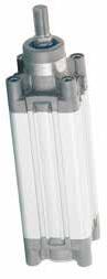
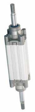
Functions
Single acting magnetic or non-magnetic. Double acting single or double end rod, magnetic or non-magnetic, cushioned or non-cushioned and tandem.
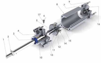
Bores from 32 to 125 mm
Standard Strokes from 25 to 1000 mm
Strokes on demand: up to 2700 mm
14.44
SERIES X - ISO 15552
NBR o-ring seals
FKM
NBR o-ring seals or FKM
Standard 1907/2006 2011/65/CE PED 2014/68/UE SILICON FREE ATEX 2014/34/UE X Series Page 350
9
10 Sintered
bearing 11 Polyurethane piston seals or FKM 12 Plastoferrite magnet 13 Aluminum piston 14 Support magnet 15 Aluminum piston 16
or
17
Reference
FORCES, SPRING LOADS AND AIR CONSUMPTION
See Pg. 14.42-14.43
0 32
0025
VS XH
14.45
Stroke (mm) 0025 0050 0075 0080 0100 0125 0150 0160 0200 0250 0300 0320 0350 0400 0450 0500 0600 0700 0800 0900 1000 Series XB Singleacting-magnetic XH Doubleacting-cushioned-magnetic XL Doubleacting-cushioned-magnetic withdoublerodend Ø (mm) 032 040 050 063 080 100 125
Special version VS OnlyRodSealsinFKM IS Stainlesssteelrod V AllFKMseals R MetalScraper
Intermediateorlongerstrokes areavailableuponrequest. Maximumstroke2700mm. Ø(mm) Stroke(mm) 25 50 75 80 100 125 150 160 200 250300 320 350 400 450 500 600 700 800 900 1000 32 40 50 63 80 100 125
X Series Page 351
DOUBLE ACTING - CUSHIONED - MAGNETIC
XL
DOUBLE ACTING - CUSHIONED - MAGNETIC WITH DOUBLE ROD END
14.46
XH
TG SW2 TG RT BG EE EE AM VD L2 WH L8 + PL J3 ØBA VA Z+ MM KK ØB d11 PL L7 J2 SW3 SW 1 SW E E + = Add Stroke ØØB d11 VD VA L2 WH ØmmSW KK AM SW1 ZJ L8 BG RT SW2 E TG EE PL J3 J2 L7 SW3 32 3010420261210M10X1.2522171209418M664632.5G1/81846.522.5 40 3510.5422301613M12X1.25241913510518M665438G1/417.53.585.82.5 50 4011.5428372017M16X1.5322214310620M886446.5G1/420.571024 63 4515429372017M16X1.5322215812120M887456.5G3/822118.544 80 4515.7435462522M20X1.5403017412819M1069472G3/822118.544 100 5519.243851.52522M20X1.54030189.513819M10611189G1/226912.554 125 6020650653227M27X2544122516021M128135110G1/230912.52.54 AMWH WH + stroke L8 + stroke AM KK VD L2 BG RT PL SW 1 SW 2 EE EE SW3 PL øB VD SW2 TG J2 J3 TG E E + = Add Stroke ØØB d11 VD VA L2 WH ØmmSW KK AM SW1 ZJ L8 BG RT SW2 E TG EE PL J3 J2 L7 SW3 32 3010420261210M10X1.2522171209418M664632.5G1/81846.522.5 40 3510.5422301613M12X1.25241913510518M665438G1/417.53.585.82.5 50 4011.5428372017M16X1.5322214310620M886446.5G1/420.571024 63 4515429372017M16X1.5322215812120M887456.5G3/822118.544 80 4515.7435462522M20X1.5403017412819M1069472G3/822118.544 100 5519.243851.52522M20X1.54030189.513819M10611189G1/226912.554 125 6020650653227M27X2544122516021M128135110G1/230912.52.54
KEY = Socket head screw with female thread for mounting attachments.
= Adjustment screw for adjustable end-position cushioning.
X Series Page 352
= Slot for proximity sensor.
= Socket head screw with female thread for mounting attachments. = Adjustment screw for adjustable end-position cushioning.
SERIES X - WITH PISTON LOCK ISO 15552
XHB
DOUBLE ACTING - CUSHIONED - MAGNETIC WITH PISTON ROD LOCK
14.47
SINGLE
- MAGNETIC TG SW2 TG RT BG EE EE AM VD L2 WH L8 + PL J3 ØBA VA Z+ MM KK ØB d11 PL L7 J2 SW3 SW 1 SW E E + = Add Stroke ØØB d11 VD VA L2 WH ØmmSW KK AM SW1 ZJ L8 BG RT SW2 E TG EE PL J3 32 3010420261210M10X1.25221714511918M664632.5G1/8184 40 3510.5422301613M12X1.25241916013018M665438G1/417.53.5 50 4011.5428372017M16X1.5322216813120M886446.5G1/420.57 63 4515429372017M16X1.5322218314620M887456.5G3/8228 80 4515.7435462522M20X1.5403019915319M1069472G3/82211 100 5519.243851.52522M20X1.54030214.516319M10611189G1/2269 KEY
XB
ACTING
= Slot for proximity sensor.
XLB:AVAILABLEDOUBLERODEND L8+STROKE B CD H L O N M F P Q G Q P ØABCDEFGHLMNOPQ L8 32 30862633.2591/8”GM686067.56204732.594 40 34.51003042.591/8”GM6870806205438105 50 40127375812.51/8”GM812901008246546.5106 63 45127375917.51/8”GM812901008247556.5121 80 45156466917.51/4”GM101611012012329572128 100 551615169201/4”GM1016110120123211489138 125 602056584.5191/4”GM12201401562045138110160 Pressures Without Pressures: LOCKED Cylinder Supply Pressure Minimum release pressure 0 ÷ 7 bar (0÷0.7Mpa) 2.5 bar (0.25Mpa) 7 ÷ 10 bar (0.7÷1Mpa) 3 bar (0.3Mpa) Bar X Series Page 353
For further information please contact our tecnichal departement.
SERIES X - TANDEM ISO 15552
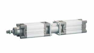
14.48
L8+ STROKE H L8+STROKE WH AM T+STROKE Ø VA WH AM LB H T 32 426229455295 40 4302410555323 50 4373210668353 63 4373212168383 80 4464012892438 100 451.54013892463.5 125 66554160120565
X Series Page 354
Bar
TECHNICAL CHARACTERISTICS
SERIES E - C YLINDER ISO 6431
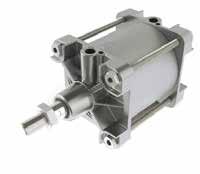
Functions
Double acting single or double end rod, magnetic or non-magnetic.
Pressures
1 bar (0.1 MPa) / 14.5 psi 10 bar (0.7 MPa) / 145 psi
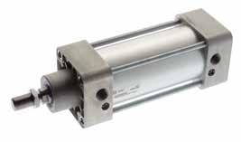
Media Filtered
See Pg. 14.42-14.43
14.49
Ø 32 - 125 Ø 160 - 320
0 °C / 32 °F (-20 °C / -4 °F with dry air) + 80 °C / 176 °F
Temperatures
and lubricated or non-lubricated compressed air.
Standard 1907/2006 2011/65/CE PED 2014/68/UE SILICON FREE ATEX 2014/34/UE Ø (mm) 032 040 050 063 080 100 125 160 200 250 320 0
Mounting type T Anodizedaluminium tuberoundprofile withtierods
Special version VS OnlyRodSealsinFKM IS Stainlesssteelrod V AllFKMseals R MetalScraper (160-200-250) VS Serie EH Doubleacting-cushioned-magnetic EL DoubleActing-cushioned-magnetic withdoublerodend
Stroke (mm) 0025 0050 0075 0080 0100 0125 0150 0160 0200 0250 0300 0320 0350 0400 0450 0500 0600 0700 0800 0900 1000
Maximumstroke2700mm. Ø(mm) Stroke(mm) 25 50 75 80 100 125 150 160 200 250300 320 350 400 450 500 600 700 800 900 1000 32 40 50 63 80 100 125 160 200 250 320
Reference
32
T E H
0025
Intermediateorlongerstrokesareavailableuponrequest.
FORCES, SPRING LOADS AND AIR CONSUMPTION E Series Page 355
EH T
DOUBLE ACTING - CUSHIONED - MAGNETIC
EL T
DOUBLE ACTING - CUSHIONED - MAGNETIC WITH DOUBLE ROD END
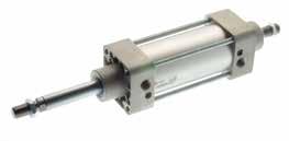
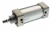
14.50
L2 WH EE EE L8+ stroke PL VA PL KK Ø MM ØB ØB BG AM L3 RT SW SW1 TG E E TG Ø Ø B VA L2 WH Ø mm SW KK A L8 BG RT E TG EE PL L3 ZM SW1 32 30420261210M10X1.25229416M64732.5G1/814514617 40 35422301613M12X1.252410516M65338G1/416516519 50 40428372017M16X1.53210616M86546.5G1/421518022 63 45428372017M16X1.53212116M87556.5G3/822519522 80 45434462522M20X1.54012818M109572G3/823622030 100 5543851.52522M20X1.54013818M1011589G1/226624030 125 60550653227M27X25416019M12140110G1/230629041 160 65655804036M36X27218024M16180140G3/429034055 200 75660954036M36X27218024M16220175G3/429037055 250 9010751055046M42X28420025M20275220G1”31041065 320 11010901206355M48X29622030M24350270G1”30046075 L2 WH EE PL KK L8 + stroke ZM+2 stroke PL EE L3 BG AM RT SW SW1 TG E E TG Ø Ø B VA L2 WH Ø mm SW KK A L8 BG RT E TG EE PL L3 ZM SW1 32 302020261210M10X1.25229416M64732.5G1/814514617 40 352222301613M12X1.252410516M65338G1/416516519 50 402828372017M16X1.53210616M86546.5G1/421518022 63 452828372017M16X1.53212116M87556.5G3/822519522 80 453434462522M20X1.54012818M109572G3/823622030 100 55383851.52522M20X1.54013818M1011589G1/226624030 125 605050653227M27X25416019M12140110G1/230629041 160 655555804036M36X27218024M16180140G3/429034055 200 756060954036M36X27218024M16220175G3/429037055 250 9075751055046M42X28420025M20275220G1”31041065 320 11090901206355M48X29622030M24350270G1”30046075 E Series Page 356
Bar
SERIES V - STAINLESS STEEL - ISO 15552
TECHNICAL CHARACTERISTICS
Component Parts and Materials
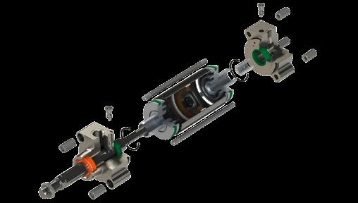
1 316 stainless steel piston rod
2 Rod seal
3 Sinterized bronze bushing
4 304 Stainless steel end cap
5 PU seal
6 304 stainless steel tube
7 Piston seal
8 Bonded ferrite magnet
9 Piston wear band
10 Aluminium piston
11 316 stainless steel cushion adjustment screw
12 304 stainless steel end cap
Pressures
1 bar (0.1 MPa) / 14.5 psi
10 bar (0.7 MPa) / 145 psi
Temperatures
Reference Standard
0 °C / 32 °F (-20 °C / -4 °F with dry air) + 80 °C / 176 °F
Media Filtered and lubricated or non-lubricated compressed air.
Functions
Double-acting cushioned magnetic Single or through piston rod.
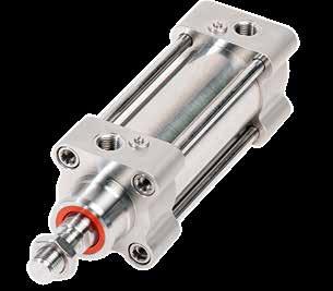
Bores from 32 to 125 mm
Standard Strokes from 25 to 1000 mm
14.51
2011/65/CE PED 2014/68/UE SILICON FREE V Series Page 357
1907/2006
FORCES, SPRING LOADS AND AIR CONSUMPTION
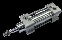
32 V HI
0025
See Pg. 14.42-14.43
VS
VHI
14.52
Stroke (mm) 0025 0050 0075 0080 0100 0125 0150 0160 0200 0250 0300 0320 0350 0400 0450 0500 0600 0700 0800 0900 1000 Series VHI Doubleacting-cushioned-magnetic VLI Doubleacting-cushioned-magnetic withdoublerodend Ø (mm) 032 040 050 063 080 100 125 0
Special version VS OnlyRodSealsinFKM V AllFKMseals
Intermediateorlongerstrokes areavailableuponrequest. Maximumstroke2700mm. Ø(mm) Stroke(mm) 25 50 75 80 100 125 150 160 200 250300 320 350 400 450 500 600 700 800 900 1000 32 40 50 63 80 100 125
DOUBLE ACTING - CUSHIONED - MAGNETIC RT BG J3 L7 PL D2 L8 + STROKE BA J2 VA VD EE WH AM KK MM B SW1 SW2 C E E SW3 TG TG KF AF WH MM SW1 Ø AM AF ØB(d11) ØBA (d11) BG ØD2 E EE J2 J3 KFKK L2 L7 L8+ Ømm PL RT SW1 SW2SW3 TG VA VD WH 32 2212303016648G1/8"6.65.3M6M10x1.25187.2941213M61017632.54526 40 2412353516652G1/4"8.55M8M12x1.25229.21051614M613196384530 50 3216404016865G1/4"86M8M16x1.525.591062014M81724846.54637 63 3216454516875G3/8"106.5M10M16x1.5269.51212016M81724856.54637 80 40204545181095G3/8"88M10M20x1.532111282516M10223010724746 100 402055551810115G1/2"157M12M20x1.538121382518M10223010894751 125 543260602012140G1/2"137M16M27x246121603218M122741-11061065
V Series Page 358
DOUBLE
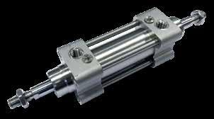
14.53
VLI
ROD END RT BG J3 L7PL D2 L8+ STROKE J2 VD EE WH AM KK MM B WH SW1 SW2 C E E SW3 TG TG KF AF WH MM WH+ SW1 Ø AM AF ØB (d11) BG ØD2 E EE J2 J3 KFKK L2 L7 L8+ Ømm PL RT SW1 SW2SW3 TG VA VD WHWH 32 22123016648G1/8"6.65.3M6M10x1.25187.2941213M61017632.5452626 40 24123516652G1/4"8.55M8M12x1.25229.21051614M61319638453030 50 32164016865G1/4"86M8M16x1.525.591062014M81724846.5463737 63 32164516875G3/8"106.5M10M16x1.5269.51212016M81724856.5463737 80 402045181095G3/8"88M10M20x1.532111282516M1022301072474646 100 4020551810115G1/2"157M12M20x1.538121382518M1022301089475151 125 5432602012140G1/2"137M16M27x246121603218M122741-1106106565
Series Page 359
ACTING - CUSHIONED - MAGNETIC WITH DOUBLE
V
SERIES NHA - TWIN ROD CYLINDER - ISO 15552
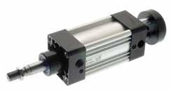
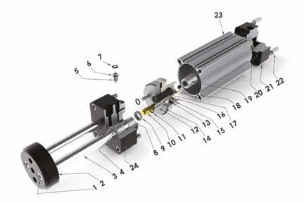
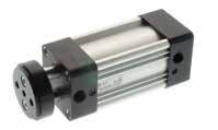
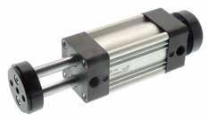
TECHNICAL CHARACTERISTICS
Component Parts and Materials
1 Galvanized steel fixing screw
2 Anodized aluminium tooling plate
3 Chromium plated steel or stainless steel piston rods
4 Polyurethane rod seal
5 Galvanized steel cushion adjustment screw
6 NBR o-ring 7 Steel elastic ring
14.54
0 °C / 32 °F (-20 °C / -4 °F with dry air) + 80 °C / 176 °F
Filtered and lubricated or non-lubricated compressed air.
Temperatures
Media
bar (0.1 MPa) / 14.5 psi 10 bar (0.7 MPa) / 145 psi
from 32 to 100 mm
Strokes from 25 to 500 mm Strokes on demand.
Single or through piston rod magnetic.
Pressures 1
Bar Bores
Standard
Functions Double-acting cushioned magnetic.
8
9 Polyurethane cushion seal 10 Brass cushion spear 11 NBR o-ring 12 Galvanized steel fixing screw 13 Bonded ferrite magnet 14 Aluminium front piston 15 Polyurethane piston seal 16 Acetal resin piston 17 NBR o-ring 18 Steel grub screw 19 Galvanized steel nut 20 Polyurethane cushion seal 21 Die-cast aluminum end cap 22 Galvanized steel fixing screw 23 Anodized aluminium tube 24 Die-cast aluminum end cap Reference Standard 1907/2006 2011/65/CE PED 2014/68/UE SILICON FREE ATEX 2014/34/UE NHA Series Page 360
Steel bearing
14.55 Cylinder Piston Rod Piston Area Operating pressure Ø Ø mm2 mm2 bar 1234 Output force N 32 8 100.48 Extend=80472144215287 Retract=703.5254108161215 40 10 157 Extend=1257110220330440 Retract=110084168252336 50 12 226.08 Extend=1963175350526701 Retract=1736.92135270404539 63 16 401.92 Extend=31172805608401120 Retract=2715.08206413619826 80 20 628 Extend=502745090013501800 Retract=439933667310091345 100 20 628 Extend=7854700140021002800 Retract=7226589117717662355 Cylinder Piston Rod Piston Area Operating pressure Ø Ø mm2 mm2 bar 1234 Air consuption for each 10 mm of stroke Nl 32 8 100.48 Extend=8040.0160.0320.0480.064 Retract=703.520.0120.0240.0360.048 40 10 157 Extend=12570.0250.0500.0750.100 Retract=11000.0190.0380.0570.075 50 12 226.08 Extend=19630.0390.0790.1180.157 Retract=1736.920.0300.0600.0910.121 63 16 401.92 Extend=31170.0620.1250.1870.249 Retract=2715.080.0460.0920.1390.185 80 20 628 Extend=50270.1000.2010.3010.402 Retract=43990.0750.1510.2260.301 100 20 628 Extend=78540.1570.3140.4710.628 Retract=72260.1320.2640.3960.528 Extend and Retract Forces Air Consumption Ø (mm) 032 040 050 063 080 100 0 32 Series NHA Doubleacting-cushioned-magnetic NLA Doubleacting-doublerodcushioned magnetic NQA Doubleacting-cushioned-magnetic withdoublerodend
HA Special version IS Stainlesssteelrod IS
Stroke (mm) 0025 0050 0080 0100 0125 0160 0200 0250 0320 0350 0400 Intermediateorlongerstrokes areavailableuponrequest. Ø(mm)Stroke(mm) 25 50 80 100 125 160 200 250 320 350 400 500 32 40 50 63 80 100 Mounting type G Anodizedaluminiumtube lobedprofilewithslots G
N
0025
NHA Series Page 361
FORCES AND AIR CONSUMPTION
NHA
DOUBLE ACTING - CUSHIONED - MAGNETIC
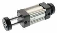
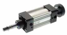
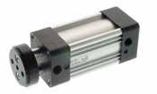
NLA
DOUBLE
NQA
14.56
MAGNETIC
ACTING - DOUBLE ROD - CUSHIONED -
ACTING - CUSHIONED - MAGNETIC WITH DOUBLE ROD ENDS TG E TG E M M K ØB PL VA EE Ø T ØV ØS C H F EE L3 L8 + stroke Z BG RT Ø Ø B d11 CEFHKMSTVZ F1 VA L2 WH ØmmSW KKL8 BG RT E TG EE PL L3 ZM 32 302647415M69.5358321848420261210M10X1.259416M64732.5G1/8145146 40 353053415M811.254510402254422301613M12X1.2510516M65338G1/4165165 50 403765518M8155512502669428372017M16X1.510616M86546.5G1/4215180 63 453775522M10197016633569428372017M16X1.512116M87556.5G3/8225195 80 454695522M12258520804086434462522M20X1.512818M109572G3/8236220 100 5551115522M123510520100509143851.52522M20X1.513818M1011589G1/2266240 TG E TG E M M K Ø T ØV ØS C H F EE L3 Z L8+ stroke L2 F1 + stroke A KK ØB Ø MM BG RT SW SW1 ØA Ø B d11 CEFHKMSTVZ F1 VA L2 WH ØmmSW KKL8 BG RT E TG EE PL L3 ZM 32 22302647415M69.5358321848420261210M10X1.259416M64732.5G1/8145146 40 24353053415M811.254510402254422301613M12X1.2510516M65338G1/4165165 50 32403765518M8155512502669428372017M16X1.510616M86546.5G1/4215180 63 32453775522M10197016633569428372017M16X1.512116M87556.5G3/8225195 80 40454695522M12258520804086434462522M20X1.512818M109572G3/8236220 100 405551115522M123510520100509143851.52522M20X1.513818M1011589G1/2266240 TG E TG E M M K Ø T ØV ØS C H F EE L3 L8 + stroke Z C + stroke BG RT Ø Ø B d11 CEFHKMSTVZ F1 VA L2 WH ØmmSW KKL8 BG RT E TG EE PL L3 ZM 32 302647415M69.5358321848420261210M10X1.259416M64732.5G1/8145146 40 353053415M811.254510402254422301613M12X1.2510516M65338G1/4165165 50 403765518M8155512502669428372017M16X1.510616M86546.5G1/4215180 63 453775522M10197016633569428372017M16X1.512116M87556.5G3/8225195 80 454695522M12258520804086434462522M20X1.512818M109572G3/8236220 100 5551115522M123510520100509143851.52522M20X1.513818M1011589G1/2266240
DOUBLE
KEY
= Socket head screw with female thread for mounting attachments.
= Adjustment screw for adjustable end-position cushioning.
NHA Series Page 362
= Slot for proximity sensor.
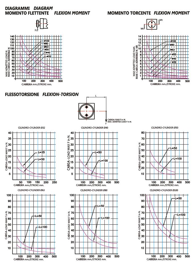
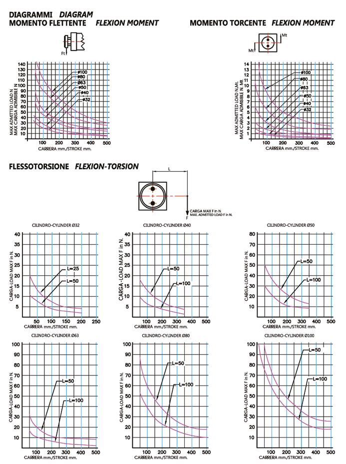
14.57 CORSA mm / STROKE mm CORSA mm / STROKE mm CORSA mm / STROKE mm NHA CYLINDER LOAD CHARTS N mm mm mm mm mm mm mm N N N N N N Maximum Transverse and Torsional Loads by bore MaxloadFinN Ø 32 Ø 63 Ø 40 Ø 80 Ø 50 Ø 100 NHA Series Page 363
TECHNICAL CHARACTERISTICS
SERIES W - COMPACT CYLINDERS - ISO 21287
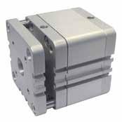
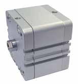
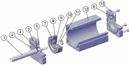
Component Parts and Materials
1 (ø12-25) 303 Stainless steel piston rod (ø32-100) chrome plated steel piston rod
2 Anodized aluminum end cap
3 Zinc plated steel screw
4 Polyurethane rod seal
5 Sintered bronze rod bearing
6 NBR o-ring seals
7 Polyurethane piston seal
8 Bonded ferrite magnet
9 Aluminum piston
10 NBR o-ring seals
11 Zinc plated steel piston nut
12 Anodized aluminum body
Reference Standard W Series Page 364
Standard Strokes from 5 to 200 mm
14.58
0 °C / 32 °F (-20 °C / -4 °F with dry air) + 80 °C/ 176 °F
and lubricated or non-lubricated compressed air.
Temperatures
Media Filtered
MPa) / 14.5 psi
Pressures 1 bar (0.1
10 bar (0.7 MPa) / 145 psi Bar Bores from 20 to 100 mm
Functions Single and double-acting magnetic. Single, through piston rod and anti rotation.
13 Anodized aluminum end cap 1907/2006 2011/65/CE PED 2014/68/UE SILICON FREE ATEX 2014/34/UE
FORCES, SPRING LOADS AND AIR CONSUMPTION
Extend and Retract Forces
14.59 Cylinder Piston Rod Piston Area Operating pressure Ø Ø mm2 bar 12345678910 Output force (N) 20 10 Extend=31428558511014017019522025028 Retract=23521426085105125150170190210 25 10 Extend=4904488132176220264308352396440 Retract=4123672108144180216252288324360 32 12 Extend=80472144216288360432504576648720 Retract=69162124186248310372434496558620 40 12 Extend=12571102203304405506607708809901100 Retract=11441002003004005006007008009001000 50 16 Extend=196317535052570087510501225140015751750 Retract=17621553104656207759301085124013951550 63 16 Extend=31172805608401120140016801960224025202800 Retract=29162605207801040130015601820208023402600 80 20 Extend=502745090013501800225027003150360040504500 Retract=471242084012601680210025202940336037804200 100 25 Extend=7854700140021002800350042004900565063607000 Retract=7363660132019802640330039604620528059406600
Spring Loads Cylinder Load spring Stroke (mm) Ø 5 10 15 20 25 Output force (N) 20 Loadofspringatrest15.71412.210.48.7 Loadofcompressedspring17.417.417.417.417.4 25 Loadofspringatrest19.518.517.31615 Loadofcompressedspring2222222222 32 Loadofspringatrest27.825.322.820.217.7 Loadofcompressedspring3030303030 40 Loadofspringatrest36.43431.729.527 Loadofcompressedspring3636363636 50 Loadofspringatrest3230.52927.826.5 Loadofcompressedspring3535353535 63 Loadofspringatrest6158.556.353.551.5 Loadofcompressedspring64.864.864.864.864.8 80 Loadofspringatrest91.388858278.7 Loadofcompressedspring9494949494 100 Loadofspringatrest150145140134129 Loadofcompressedspring156156156156156 Air consumption Cylinder Piston Rod Piston Area Operating pressure Ø Ø mm2 bar 12345678910 Air consuption for each 10 mm of stroke (Nl) 20 10 Extend=3140.0060.0090.0130.0160.0190.0220.0250.0280.0310.035 Retract=2350.0050.0070.0090.0120.0140.0160.0190.0210.0240.026 25 10 Extend=4900.0100.0150.0200.0250.0290.0340.0390.0440.0490.054 Retract=4120.0080.0120.0160.0210.0250.0290.0330.0370.0410.045 32 12 Extend=8040.0160.0240.0320.0400.0480.0560.0640.0720.0800.088 Retract=6910.0140.0210.0280.0350.0410.0480.0550.0620.0690.076 40 12 Extend=12570.0250.0380.0500.0630.0750.0880.1010.1130.1260.138 Retract=11440.0230.0340.0460.0570.0690.0800.0920.1030.1140.126 50 16 Extend=19630.0390.0590.0790.0980.1180.1370.1570.1770.1960.216 Retract=17620.0350.0530.0700.0880.1060.1230.1410.1590.1760.194 63 16 Extend=31170.0620.0940.1250.1560.1870.2180.2490.2810.3120.343 Retract=29160.0580.0870.1170.1460.1750.2040.2330.2620.2920.321 80 20 Extend=50270.1010.1510.2010.2510.3020.3520.4020.4520.5030.553 Retract=47120.0940.1410.1880.2360.2830.3300.3770.4240.4710.518 100 25 Extend=78540.1570.2360.3140.3930.4710.5500.6280.7070.7850.864 Retract=73630.1470.2210.2950.3680.4420.5150.5890.6630.7360.810
W Series Page 365
Doubleacting-cushioned-magnetic withdoublerodend
Doubleacting-magnetic-antirotation
14.60 Ø (mm) 020 025 032 040 050 063 080 100 Series WB - WBM
WD - WDM
WF
WJ
WFA
Version =Standardfemalerod M =Malerod(NOWFA) Stroke (mm)
0005 0010 0015 0020 0025 0030 0040 0050 0060 0080 0100 0125 0150 0160 0200 Ø(mm) Stroke(mm) 5 10 15 20 2530 40 50 60 80 100 125 150 200 20 25 32 40 50 63 80 100 Intermediateorlongerstrokes areavailableuponrequest. W Series Page 366
Singleacting-magnetic
Singleacting-magnetic-springextend
- WFM Doubleacting-magnetic
- WJM
WB 0 20 0025
WB - WBM
SINGLE ACTING - MAGNETIC
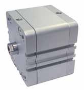
14.61
EE CH TG E L1 TG E RT AF KF LA BG Ø D1 T1 ZA+ ZB+ Ø D ZA+ ZB+ A KK PL PL EE E CH TG TG E RT AF KF ZA+ ZB+ Ø D G G T1 D1 PL PL ZA+ ZB+ G G A KK Ø 20-25 Ø 32-40-50-63-80-100 * Like UNITOP + = Add Stroke Ø Ø D E L1 A KK CH AF KF BG LA RT G TG EE PL Ø D1 T1 ZA+ ZB+ *20 10361.516M8x1.25910M618.55M5-22M58*6*4*39*45 *25 10401.516M8x1.25910M618.55M5-26M58*6*43945.5 32 1249-19M10x1.251012M8--M614.532.5G1/87.592.14451 40 1255-19M10x1.251012M8--M61538G1/87.592.14552 50 1668-22M12x1.251316M10--M814.546.5G1/87.5122.64553 63 1678.5-22M12x1.251316M10--M81456.5G1/87.5122.64957.5 80 2098-28M16x1.51720M12--M1015.572G1/87.5122.65464 100 25120-28M16x1.52220M12--M102089G1/87.5122.66777 W Series Page 367
WD - WDM
SINGLE ACTING - MAGNETIC - SPRING EXTEND
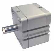
14.62
EE CH TG EL1 TG E RT AF KF LA BG Ø D1 T1 ZA+ ZB++ Ø D ZA+ ZB++ A KK PL PL EE E CH TG TG E RT AF KF ZA+ ZB++ Ø D GG T1 D1 PL PL ZA+ ZB++ GG A KK Ø 20-25 Ø 32-40-50-63-80-100 * Like UNITOP + = Add Stroke ++ = Double stroke dimension and add it Ø Ø D E L1 A KK CH AF KF BG LA RT G TG EE PL Ø D1 T1 ZA+ ZB++ *20 10361.516M8x1.25910M618.55M5-22M58*6*4*39*45 *25 10401.516M8x1.25910M618.55M5-26M58*6*43945.5 32 1249-19M10x1.251012M8--M614.532.5G1/87.592.14451 40 1255-19M10x1.251012M8--M61538G1/87.592.14552 50 1668-22M12x1.251316M10--M814.546.5G1/87.5122.64553 63 1678.5-22M12x1.251316M10--M81456.5G1/87.5122.64957.5 80 2098-28M16x1.51720M12--M1015.572G1/87.5122.65464 100 25120-28M16x1.52220M12--M102089G1/87.5122.66777 W Series Page 368
WF - WFM
14.63
DOUBLE ACTING
MAGNETIC EE CH TG E L1 TG E RT AF KF LA BG Ø D1 T1 ZA+ ZB+ Ø D ZA+ ZB+ A KK PL PL EE E CH TG TG E RT AF KF ZA+ ZB+ Ø D G G T1 D1 PL PL ZA+ ZB+ G G A KK Ø 20-25 Ø 32-40-50-63-80-100 * Like UNITOP + = Add Stroke Ø Ø D E L1 A KK CH AF KF BG LA RT G TG EE PL Ø D1 T1 ZA+ ZB+ *20 10361.516M8x1.25910M618.55M5-22M58*6*4*39*45 *25 10401.516M8x1.25910M618.55M5-26M58*6*43945.5 32 1249-19M10x1.251012M8--M614.532.5G1/87.592.14451 40 1255-19M10x1.251012M8--M61538G1/87.592.14552 50 1668-22M12x1.251316M10--M814.546.5G1/87.5122.64553 63 1678.5-22M12x1.251316M10--M81456.5G1/87.5122.64957.5 80 2098-28M16x1.51720M12--M1015.572G1/87.5122.65464 100 25120-28M16x1.52220M12--M102089G1/87.5122.66777 W Series Page 369
-
WJ - WJM
DOUBLE ACTING - MAGNETIC WITH DOUBLE ROD END
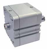
14.64
EE CH TG EL1 TG E RT AF KF ZA + ZB + LA BG Ø D ZC ++ ZA + ZB + ZC ++ AA KK KK EE E CH TG TG E RT AF KF PL PL ZA+ ZB+ D G G ZC+ + AF PL PL ZA+ ZB+ G G ZC+ + KK AA KK Ø 20-25 Ø 32-40-50-63-80-100 * Like UNITOP + = Add Stroke ++ = Double stroke dimension and add it Ø Ø D E L1 A KK CH AF KF BG LA RT G TG EE PL ZA+ ZB+ ZC++ *20 10361.516M8x1.25910M618.55M5-22M58*39*45*51 25 10401.516M8x1.25910M618.55M5-26M583945.551.5 32 1249-19M10x1.251012M8--M614.532.5G1/87.5445158 40 1255-19M10x1.251012M8--M61538G1/87.5455259 50 1668-22M12x1.251316M10--M814.546.5G1/87.5455361 63 1678.5-22M12x1.251316M10--M81456.5G1/87.54957.566 80 2098-28M16x1.51720M12--M1015.572G1/87.5546474 100 25120-28M16x1.52220M12--M102089G1/87.5677787 W Series Page 370
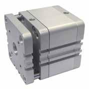
14.65
ACTING
MAGNETIC
ANTI ROTATION EE F1 F1 Ø TL EL1 E TG TG ØF ØF RT LA BG Ø D1 T1 PL PL ZA + ZB + DD 2 D3 H T2 CH F1 F1 Ø TL ØF ØF TG TG E E RT D3 D EE T1 D1 PL G PL G ZA+ HZB+ T2 D2 CH Ø 20-25 Ø 32-40-50-63-80-100 * Like UNITOP + = Add Stroke Ø Ø D E L1 CH AF KF BG LA RT G TG EE PL Ø D1 T1 Ø TL H Ø F F1 D2 D3 T2 ZA+ ZB+ *20 10361.5910M618.55M5-22M58*6*41784M4610.55*39*45 *25 10401.5910M618.55M5-26M58*6*42285M561453945.5 32 1249-1012M8--M614.532.5G1/87.592.128105M561764451 40 1255-1012M8--M61538G1/87.592.133105M561764552 50 1668-1316M10--M814.546.5G1/87.5122.642126M68227.54553 63 1678.5-1316M10--M81456.5G1/87.5122.650126M68227.54957.5 80 2098-1720M12--M1015.572G1/87.5122.665148M8122410.55464 100 25120-2220M12--M102089G1/87.5122.6801410M10122410.56777 W Series Page 371
WFA DOUBLE
-
-
CYLINDER ACCESSORIES FOR ISO 6431 - ISO 15552 - ISO 21287
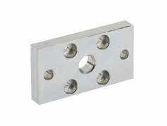
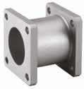
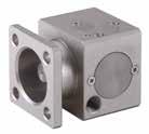
VRL
VFT
QFL
14.66
PISTON ROD LOCK MATERIAL: Aluminium
JOINING FLANGE MATERIAL: Aluminium
FLANGE MATERIAL: Steel A M H E C D L O N Q P F G G Q P B Part No. ØABCDEFGHLMNOPQ VRL 032 32 30862633.2591/8”GM686067.56204732.5 VRL 040 40 34.51003042.591/8”GM6870806205438 VRL 050 50 40127375812.51/8”GM812901008246546.5 VRL 063 63 45127375917.51/8”GM812901008247556.5 VRL 080 80 45156466917.51/4”GM101611012012329572 VRL 100 100 551615169201/4”GM1016110120123211489 VRL 125 125 602056584.5191/4”GM12201401562045138110 H D Part No. Ø H D VFT 032 32 5545 VFT 040 40 5552 VFT 050 50 6865 VFT 063 63 6875 VFT 080 80 9295 VFT 100 100 92115 VFT 125 125 120140 Part No. Ø A B C D E F G H I L M QFL 012 12-16 18435518294.595.5105.410 QFL 020 20 22557022365.5106.6105.412 QFL 025 25 26607626405.5106.6105.412
Screw included.
Page 372
Cylinder Accessories
VFL
QCP
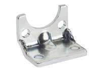
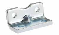
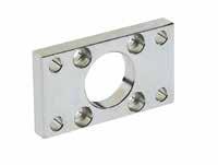
14.67
FLANGE MATERIAL: Steel MATERIAL: Stainless Steel
LOW-RISE PEDESTAL Ø 12-25 MATERIAL: Steel VCP LOW RISE PEDISTAL MATERIAL: Steel MATERIAL: Stainless Steel A ±0,2 A ±0,2 Q T R V P C D S N M H11 Part No. Part No. Ø Ø M P S D C N A Q R T V VFL 032 VFLI 032 32 307106.510.56.532.532456480 VFL 040VFLI 040 40 359106.510.56.53836527290 VFL 050VFLI 050 50 409128.513.58.546.5456590110 VFL 063VFLI 063 63 459128.513.58.556.55075100120 VFL 080VFLI 080 80 45121610.516.510.5726395126150 VFL 100VFLI 100 100 55141610.516.510.58975115150170 VFL 125 -125 60162012.52013.511090140180205 VFL 160 -160 65182016.52517140115180230260 VFL 200 -200 75222516.52517175135220270300 VFL 250 -250 90262514.53322220165285330400 VFL 320 -320 1103330153926270200350400470 Part No. Ø CBDEFGH I STRUZ QCP 012 12 - 16 18183017.517.54.41313315925.5 QCP 020 20 22223622225.416164171026.6 QCP 025 25 26264022235.417164191126.6 Part No. Part No. ØBCEFOUVRZXYH VCP 032 VCPI 032 32 43245307243515732.515.7532 VCP 040VCPI 040 40 436523010283617.57381736 VCP 050VCPI 050 50 545653610324720946.521.7545 VCP 063VCPI 063 63 550753510324522.5956.521.7550 VCP 080VCPI 080 80 663954712415522.511722763 VCP 100VCPI 100 100 6751155314.5415727.5118926.571 VCP 125VCPI 125 125 8901407016.5457030141103590 VCP 160 -160 911518011518607532.51814045115 VCP 200 -200 12135220135217010037.51817547.5135 VCP 250 -250 141652701652675100452222055165 Cylinder Accessories Page 373
VCB
LARGE LOW RISE PEDISTAL Ø 32-100
MATERIAL: Steel
VCF
CLEVIS BRACKET WITH SELF-LUBRICATING BUSHINGS
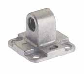
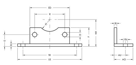
MATERIAL: Aluminium
MATERIAL: Stainless Steel
QCM
EYE BRACKET WITH SELF-LUBRICATING BUSHINGS
MATERIAL: Aluminium
14.68
Part No. Ø US ED F AO B TR ED FT NH R AU FB VCB 032 NE 32 7945303056515.756.5153232.5186.5 VCB 040 NE 40 90553030575176.517.53638186.5 VCB 050 NE 50 11065353559021.758.522.55056.5218.5 VCB 063 NE 63 120753535510021.758.522.55056.5218.5 VCB 080 NE 80 153954545612826.510.522.563722710.5 VCB 100 NE 100 178115454561482710.527.571892710.5 Part No. Part No. Ø B E G T Z CM MR VCF 032 VCFI 032 32 9451045222610 VCF 040VCFI 040 40 9521252252812 VCF 050VCFI 050 50 11651260273212 VCF 063VCFI 063 63 11751670324016 VCF 080VCFI 080 80 14951690365016 VCF 100VCFI 100 100 1411520110416020 VCF 125VCFI 125 125 2014025130507025 VCF 160VCFI 160 160 2018030170559025 VCF 200VCFI 200 200 2522030170609025 Part No. Ø ABCDEFGHILMNOPQ QCM 012 12 - 16 1827104.52.6616264.51081236 QCM 020 20 22341152.6620285.512101638 QCM 025 25 26381152.6620285.512101638
Page 374
Cylinder Accessories
VCM
EYE BRACKET
MATERIAL: Aluminium
MATERIAL: Iron
VCH
CLEVIS BRACKET
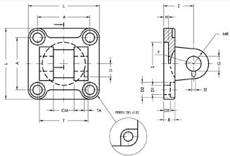
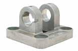
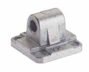
MATERIAL: Iron
VCD
NARROW CLEVIS BRACKET
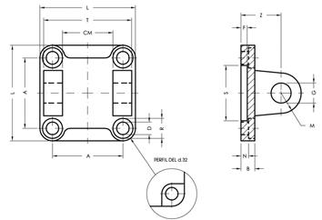
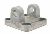
MATERIAL: Aluminium
MATERIAL: Iron
14.69
MATERIAL: Stainless Steel
MATERIAL: Aluminium
Part No. Part No. Part No. Ø B E G Z CM MR VCM 032 VCMI 032VCMZ 032 NE 32 94510222610 VCM 040VCMI 040VCMZ 040 NE 40 95212252812 VCM 050VCMI 050VCMZ 050 NE 50 116512273212 VCM 063VCMI 063VCMZ 063 NE 63 117516324016 VCM 080VCMI 080VCMZ 080 NE 80 149516365016 VCM 100VCMI 100VCMZ 100 NE 100 1411520416020 VCM 125VCMI 125VCMZ 125 NE 125 2014025507025 VCM 160VCMI 160VCMZ 160 NE 160 2018030559025 VCM 200VCMI 200VCMZ 200 NE 200 2522030609025 VCM 250 - VCMZ 250 NE 250 25270407011040 Part No. Part No. ØALDRNBSFZGM CM T VCH 032 VCHZ 032 NE 32 32.5456.6115.593052210102645 VCH 040VCHZ 040 NE 40 38526.6115.593552512122852 VCH 050VCHZ 050 NE 50 46.5659156.5114052712123260 VCH 063VCHZ 063 NE 63 56.5759156.5114553216164070 VCH 080VCHZ 080 NE 80 7295111810144553616165090 VCH 100VCHZ 100 NE 100 891151118101455541202060110 VCH 125VCHZ 125 NE 125 1101401420102060750252570130 VCH 160VCHZ 160 NE 160 1401801826102065755302590170 VCH 200VCHZ 200 NE 200 1752201826112575760302590170 VCH 250VCHZ 250 NE 250 2202702233112590-704040110200 Part No. Part No. ØLT CM AZHBD3SG MR D1 D2 TA TZ LI F VCD 032 VCDZ 032 NE 32 45341432.522595.53010106.61133.311.517 VCD 040VCDZ 040 NE 40 5240163825595.53512126.61144.31220 VCD 050VCDZ 050 NE 50 65452146.5275116.540161491544.31422 VCD 063VCDZ 063 NE 63 75512156.5325116.545161891544.31425 VCD 080VCDZ 080 NE 80 956525723651410452020111844.31630 VCD 100 VCDZ 100 NE 100 1157525894151410552022111846.31632 VCD 125VCDZ 125 NE 125 14097371105072010603025142066.32442 VCD 160 -160 180122431405572010653530182666.326.546 VCD 200 -200 220122431756072511753530182666.326.549 Cylinder Accessories Page 375
VPS
PIN WITH ANTI-ROTATION AND RETAINER CLIP FOR VCD CLEVIS BRACKET
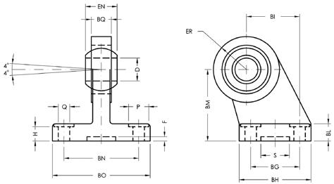
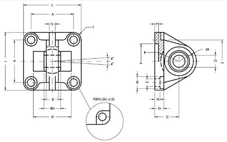
MATERIAL: Steel
MATERIAL: Stainless Steel
VCS
EYE BRACKET WITH SPHERICLE ROD EYE
MATERIAL: Aluminium
MATERIAL: Stainless Steel
MATERIAL: Iron
VADZ
EYE BRACKET WITH SPHERICLE ROD EYE MATERIAL: Steel
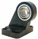
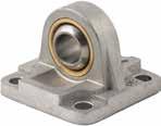
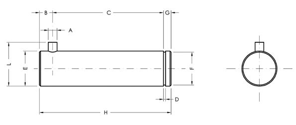
TREATMENT: Black Cataphoresis
14.70
Part No. Part No. Ø A C D E F G H L B VPS 032 VPSI 032 32 332.51.1109.6441144.5 VPS 040VPSI 040 40 4381.11211.5448166 VPS 050VPSI 050 50 4431.11615.2560206 VPS 063VPSI 063 63 4491.11615.2560206 VPS 080VPSI 080 80 4631.32019675246 VPS 100VPSI 100 100 4731.32019685246 VPS 125VPSI 125 125 6941.63028.67110369 VPS 160 - 160 - 200 61191.635337135419 Part No. Part No. Part No. ØABCD ENER FGELMNPHRSZT VCS 032 VCSI 032VCSZ 032 NE 32 32.510.5221014163096.645115.55--432.56.25 VCS 040VCSI 040VCSZ 040 NE 40 3812251216193596.652115.55--6397 VCS 050VCSI 050VCSZ 050 NE 50 46.515271621214011965156.5551188479.25 VCS 063VCSI 063VCSZ 063 NE 63 56.515321621244511975156.55--8529.25 VCS 080VCSI 080VCSZ 080 NE 80 721836202528.545141195181057224106711.5 VCS 100VCSI 100VCSZ 100 NE 100 89184120253055141111518108--107713 VCS 125VCSI 125VCSZ 125 NE 125 1102550303740602013.514020107--139815 VCS 160 - -160 140285535434565201818026107--1413020 VCS 200 - -200 175286035434875251822026117--1415522.5 Part No. ØQP BG BH BI BL BM BN BO ENER BQ DHSF VADZ 032 NE 32 6.61118312110323851141510.5108.5203 VADZ 040 NE 40 6.61122352410364154161812128.5203 VADZ 050 NE 50 915304533124550652120151610.5203 VADZ 063 NE 63 915355037125052672123151610.5203 VADZ 080 NE 80 1118406047146366862527182011.5203 VADZ 100 NE 100 1118507055157176962530182012.5203 VADZ 125 NE 125 13.5206090702090941243740253017203
Page 376
Cylinder Accessories
XCN
VCNT
VCNL
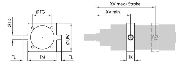
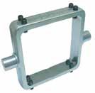
14.71
INTERMEDIATE ADJUSTABLE TRUNNION MOUNT MATERIAL: Steel
INTERMEDIATE FIXED TRUNNION MOUNT MATERIAL: Steel
INTERMEDIATE TRUNNION FOR SMOOTH TIE-RODS MATERIAL: Steel M B UW TM C TD F G E TL L N TK Part No. Ø UW BC TD EFG TK I TL MN TM XCN 032 32 65455012-54202812M5750 XCN 040 40 755362162055203216M5863 XCN 050 50 906474162066204016M6875 XCN 063 63 1007488202566255020M61290 XCN 080 80 13093109202577256420M812110 XCN 100 100 140110130253088308025M815132 XCN 125 125 1501341552530883010025M1015160 Part No. Ø TD TG TK TL TM UW XV min XV max RT VCNT 032 32 1232.51512504661.584.5M6 VCNT 040 40 16382016635971.593.5M6 VCNT 050 50 1646.52016756978.5101.5M8 VCNT 063 63 2056.52520908484.5110.5M8 VCNT 080 80 2072252011010294.5125.5M10 VCNT 100 100 25893025132125107133M10 VCNT 125 125 251103225160155126163M12 VCNT 160 160 321404032200190149191M16 VCNT 200 200 321754032250240164206M16 VCNT 250 250 402205040320296187223M20 A AE AF AH AG A M R AN Q AL Z XV min XV max + (Stroke) Part No. Ø TD TG TK TL TM UW XV min XV max VCNL 032 32 1232.51512504661.584.5 VCNL 040 40 16382016635971.593.5 VCNL 050 50 1646.52016756978.5101.5 VCNL 063 63 2056.52520908484.5110.5 VCNL 080 80 2072252011010294.5125.5 VCNL 100 100 25893025132125107133 VCNL 125 125 251103225160155126163 VCNL 160 160 321404032200190149191 VCNL 200 200 321754032250240164206
Page 377
Cylinder Accessories
VCNF

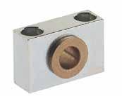
14.72
REAR HINGE
Steel
FRONT -
MATERIAL:
BLOCK
INTERMEDIATE TRUNNION MATERIAL: Steel
VSI SUPPORT
FOR
BRACKET MATERIAL: Aluminium MATERIAL: Stainless Steel 0S L A DP LP LP 0 D R 1x45° A I 0E N 0 RB L B Part No. Ø A L DP LP D S B R I E RB N VCNF 032 32 32,546501212301416.56.510.56 VCNF 040 40 385963161635191,596.510.56 VCNF 050 50 46,56975161640191,698.513.58 VCNF 063 63 56,58490202045241,611.58.513.58 VCNF 080 80 72102110202045241,611.510.516.510 VCNF 100 100 891251322525552921410.516.510 VCNF 125 125 1101501602525603021513.52012 Part No. Ø A M R P C S L U T E VSI 032 32 46183015321210.5116.67 VSI 04040 - 50 552136183616121599 VSI 06363 - 80 65234020422013181111 VSI 100100 - 125 7528.55025502516201413 VSI 160160 - 200 92406030603222.5261817 VSI 250 250 140567035904031332220 Ø D BI BG BH BM BN BO BQ ØBR ØQ Part No. Part No. Ø Q BG BH BI BM BN BO BQ BR Ø VAS 032 VASI 032 32 6.6183121323851262010 VAS 040VASI 040 40 6.6223524364154282212 VAS 050VASI 050 50 9304533455065322612 VAS 063VASI 063 63 9355037505267403016 VAS 080VASI 080 80 11406047636686503016 VAS 100VASI 100 100 11507055717696603820 VAS 125VASI 125 125 146090709094124704525 VAS 160 -160 148812697115118156906330 VAS 200 -200 1890130105135122162906330
Page 378
VAS EYE
Cylinder Accessories
VPE
PIN WITH RETAINER CLIPS

MATERIAL: Steel
MATERIAL: Stainless Steel
FC
ROD CLEVIS WITH LOCKABLE PIN
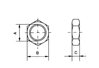
MATERIAL: Steel
MATERIAL: Stainless Steel
DA
ROD JAM NUT MATERIAL: Steel
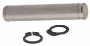
14.73
Part No. Part No. Ø G BT BU CG CH VPE 032 VPEI 032 32 1046539.61.1 VPE 040VPEI 040 40 12536011.51.1 VPE 050VPEI 050 50 12616811.51.1 VPE 063VPEI 063 63 16717815.21.1 VPE 080VPEI 080 80 16919815.21.1 VPE 100VPEI 100 100 20111118191.3 VPE 125VPEI 125 125 2513213923.91.3 VPE 160VPEI 160160 - 200 30171.517828.61.6 VPE 250 -250 4020221137.51.85 VPE 320 -320 4522223642.51.85 Part No. Part No. KK A B C E F G FC 020 *FCI 020 M8x1.25 4216321688 FC 025*FCI 025 M10x1.25 522040201010 FC 040*FCI 040 M12x1.25 622448241212 FC 050*FCI 050 M16x1.5 833264321616 FC 080*FCI 080 M20x1.5 1054080402020 *FC 125*FCI 125 M27x2 14856110553030 *FC 160*FCI 160 M36x2 18872144703535 *FC 250 - M42x2 23284168854242 *FC 320 - M48x2 26596192965050 * With pin and seeger. Part No. A B C 0DA00 00 51 C3 ZI M8x1.25 136.5 0DA00 00 51 C9 ZI M10x1.25 178 0DA00 00 51 D5 ZI M12x1.25 197 0DA00 00 51 E3 ZI M16x1.5 226 0DA00 00 51 F2 ZI M20x1.5 309 0DA00 00 51 G8 ZI M27x2 4112 EDA00 00 51 I6 ZI M36x2 5514 EDA00 00 51 L0 ZI M42x2 6520 EDA00 00 51 DG ZI M48x2 7524 Cylinder Accessories Page 379
TF
SELF-LUBRICATING SPHERICAL ROD EYE
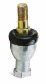
MATERIAL: Steel
TS
SELF-ALIGNING ROD END COUPLER MATERIAL: Steel
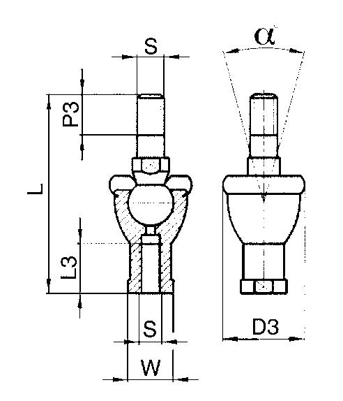
SPHERICAL ROD EYE WITH MALE THREAD MATERIAL: Steel
14.74
TM
Part No. F ABC Ø Sphere DEGH LMPSW Radial load Weight Dynamic Static 0 H7 00 -0.13 ± 0.13 ± 0.5 ± 0.5 ± 0.7 ± 0.7 ± 0.5 ± 0.7 ± 0.25kgkgg TF 020 M8x1.25 810.41215.8892436481212.5165147801.90036 TF 025 M10x1.25 1012.91419.0511.53043581515196.5161.2003.10088 TF 040 M12x1.25 1215.41622.2312.53450671817.5226.5181.4003.700120 TF 050 M16x1.5 1619.32128.5815.54264852422278242.5006.300240 TF 080 M20x1.5 2024.42534.9318.550771023027.53410303.7008.300430 TF 125 M27x2 2832.33547.59266610313641374614417.10014.2001.120 TF 160 M36x2 35-43---125-56-58----1.600 TF 250 M42x2 40-49---142-60-65----2.800 TF 320 M48x2 50-60---162-65-75----5.000 Part No. S L L3 W P3 D3 α° (kN) TS 020 M8x1.25 651614122030°3.5 TS 025 M10x1.25 74.51817152830°5 TS 040 M12x1.25 842019173230°6.7 TS 050 M16x1.5 1122722234022°7.8 TS 080 M20x1.5 1333830254515°10 Part No. F ABCØDEGH L Radial load Weight Dynamic Static TM 020 M5x0.8 57.5811.117.518334219430100013 TM 032 M6x1 68.9912.77.520364621470110015 TM 050 M8x1.25 810.41215.889.524425425780190034 TM 080 M10x1.5 1012.91419.0511.5304863281200310070 TM 100 M12x1.75 1215.41622.2312.53454713214003700110
Page 380
Cylinder Accessories
TECHNICAL CHARACTERISTICS
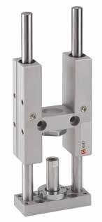
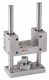
14.75
ISO 6431 VDMA (from 32 to 100) ISO 6432 (from 20 to 25) ISO 15552 (from 32 to100) Bores from 12 to 100 mm Standard Strokes from 50 to 500 mm
GUIDE UNITS
Reference Standard 1907/2006 2011/65/CE PED 2014/68/UE SILICON FREE Series
Guideunit“U”withselflubricatingsinteredbronzebushings
Guideunit“H”withselflubricatingsinteredbronzebushings MLCHC Guideunit“H”withrecirculatingballsleeves VLCUB Guideunit“U”withselflubricatingsinteredbronzebushings VLCHB Guideunit“H”withselflubricatingsinteredbronzebushings VLCHC Guideunit“H”withrecirculatingballsleeves MLCUB Ø (mm) 012 020 025 032 040 050 063 080 100 0 12 Stroke (mm) 0050 0050 0100 0160 0200 0250 0320 0400 0500 Intermediateorlongerstrokesare availableuponrequest. Ø(mm) Stroke(mm) 50 100 160 200 250 320 400 500 12 - 16 20 25 32 40 50 63 80 100 Guided Units Page 381
MLCUB
MLCHB
14.76 MAXIMUM LOADS N Max load mm Stroke Art. MLCHB Guide units with self lubricating sintered bronze bushings Ø20 - Ø25 250 200 150 100 50 0 250 200 150 100 50 Ø12 - Ø16 Ø20 - Ø25 250 200 150 100 50 0 250 200 150 100 50 Ø12 - Ø16 mm N Art. VLCHB Guide units with self lubricating sintered bronze bushings 500 400 300 200 100 0 50 250 150 350450 600 700 800 900 1000 Ø80 - Ø100 Ø63 Ø50 Ø40 Ø32 500 400 300 200 100 0 50 250 150 350450 600 700 800 900 1000 Ø80 - Ø100 Ø63 Ø50 Ø40 Ø32 N mm N Art. MLCHC Guide units with recirculating ball bearing 50 100 150 200 250 0 20 40 60 80 100 120 140 160 Ø20 - Ø25 Ø12 - Ø16 50 100 150 200 250 0 20 40 60 80 100 120 140 160 Ø20 - Ø25 Ø12 - Ø16 mm Art. VLCHC Guide units with recirculating ball bearing 50 100 150 200 250 0 100 200 300 400 500 600 300350400450500 Ø80 - Ø100 Ø63 Ø50 Ø40 Ø32 50 100 150 200 250 0 100 200 300 400 500 600 300350400450500 Ø80 - Ø100 Ø63 Ø50 Ø40 Ø32 N mm Guided Units Page 382
Guide units with self lubricating sintered bronze bushings
14.77
Art. VLCUB
Ø63 Ø50 Ø40 Ø20-25-32 Ø16 Ø80 Ø100 0 100200 300400 500 600 50 100 150 200 250 300 350 400 450 500 550 600 650 700 750 800 850 900 Ø63 Ø50 Ø40 Ø20-25-32 Ø16 Ø80 Ø100 0 100200 300400 500 600 50 100 150 200 250 300 350 400 450 N mm Guided Units Page 383
MLCUB
WITH SELF-LUBRICATING SINTERED BRONZE
14.78
GUIDE UNIT “U”
BUSHINGS ISO 6432 CH2 CH1 CH3 U X P N Q Ø1 W L4 + STROKE J Y K H L2 L1 C Z L6 + STROKE R T S L3 D D1 M O L5 + STROKE E W B A T1 V F X G ØABC CH1 CH2 CH3 D D1 EFGH Ø1 JK L1 L2 L3 L4 L5 L6 12 - 16 69303081024125.519.566291010M4M43153866.57315.5 20 793437121327178.7524.2578321212M5M651848838718 25 793437121727178.7524.2578321212M5M651848839118 ØMNOPQRST T1 UVWXYZ 12 - 16 64.567.54.55.595.532245825182249.5 20 85.59107.56.5116.538386832.5202358 25 85.59107.56.5116.538386832.5202358 Ø(mm)Stroke(mm) 50 100 160 200 12 - 16 20 25 Guided Units Page 384
MLCHB
14.79
GUIDE UNIT “H” WITH SELF-LUBRICATING SINTERED BRONZE BUSHINGS ISO 6432 N P X J Q Z U H L2 L1 T1 W L5 + STROKE T S R K D1 L4 D M O L3 Ø1 Y L7 + STROKE C A B V F W E L6 + STROKE X G Ch.3 Ch.2 Ch.1 Fattener ØABC CH1 CH2 CH3 D D1 EFGH Ø1 JK L1 L2 L3 L4 L5 L6 12 - 16 69303081024126866291010M4M425184668123.573 20 793437121327178.51578321212M5M625405810816687 25 793437121727178.51578321212M5M625405810816691 Ø L7 MNOPQRST T1 UVWXYZ 12 - 16 1264.5684.55.595.532245818182249.5 20 1085.59107.56.5116.538386832.5202358 25 1085.59107.56.5116.538386832.5202358 Ø(mm)Stroke(mm) 50 100 160 200 250 12 - 16 20 25 Guided Units Page 385
14.80
GUIDE UNIT “H” WITH RECIRCULATING BALL SLEEVES ISO 6432 N P X J Q Z U H L2 L1 T1 W L5 + STROKE T S R K D1 L4 D M O L3 Ø1 Y L7 + STROKE C A B V F W E L6 + STROKE X G Ch.3 Ch.2 Ch.1 Fattener ØABC CH1 CH2 CH3 D D1 EFGH Ø1 JK L1 L2 L3 L4 L5 L6 12 - 16 69303081024126866291010M4M425184668123.573 20 793437121327178.51578321212M5M625405810816687 25 793437121727178.51578321212M5M625405810816691 Ø L7 MNOPQRST T1 UVWXYZ 12 - 16 1264.5684.55.595.532245818182249.5 20 1085.59107.56.5116.538386832.5202358 25 1085.59107.56.5116.538386832.5202358 Ø(mm)Stroke(mm) 50 100 160 200 250 12 - 16 20 25 Guided Units Page 386
MLCHC
14.81
BUSHINGS ISO 15552 D Ch2 Ch1 N V Q P V L4 + STROKE R S H L1 L2 Z L5 + STROKE V M L3 O B A C S E V L6 + STROKE ø1 V G V U F T O ØABC CH1 CH2 DEFGH Ø1 L1 L2 L3 L4 L5 L6 MNO 32 9749511517179.2593451212422548102189786.612 40 1155858.5151921111125512164324581131710976.612 50 1377070.220242518.8134651520493059123201106916 63 1528585.220242515.3147801520493076140211256916 ØPQRSTUVZ 32 116.5M6M6786132.574 40 116.5M6M684693887 50 158.5M8M81008546.5104 63 159M8M810510056.5119 Ø(mm)Stroke(mm) 50 100 160 200 250 320 400 500 32 40 50 63 Guided Units Page 387
VLCUB GUIDE UNIT “U” WITH SELF-LUBRICATING SINTERED BRONZE
VLCHB
WITH SELF-LUBRICATING SINTERED BRONZE
14.82
GUIDE UNIT “H”
BUSHINGS ISO 15552 Fattener L7 + STROKE P V N Q R HL1 L2 L5 + STROKE S D L4 V L3 Z M E V O Ø1 V L6 + STROKE B A V U T F V G ØABC CH1 CH2 DEFGH Ø1 L1 L2 L3 L4 L5 L6 L7 MNO 32 9749511517244.393451212254275125187259786.612 40 1155858.2151928111125512162542801402073010976.612 50 1377070.220243418.8134651520255078148223351106916 63 1528585.220243415.31478015202550106178243251256916 80 189105105.526305025180100202525501111952672713391120 100 213130130.526305530206120202525501282182902714491120 ØPQRSTUVZ 32 116.5M6M6786132.574 40 116.5M6M684693887 50 158.5M8M81008546.5104 63 159M8M810510056.5116 80 1811M10M1013013072148 100 16.511M10M1015015089173 Ø(mm)Stroke(mm) 50 100 160 200 250 320 400 500 32 40 50 63 80 100
Units Page 388
Guided
14.83 VLCHC GUIDE UNIT “H” WITH RECIRCULATING BALL SLEEVES ISO 15552 Fattener L7 + STROKE P V N Q R HL1 L2 L5 + STROKE S D L4 V L3 Z M E V O Ø1 V L6 + STROKE B A V U T F V G ØABC CH1 CH2 DEFGH Ø1 L1 L2 L3 L4 L5 L6 L7 MNO 32 9749511517244.393451212254275125187259786.612 40 1155858.2151928111125512162542801402073010976.612 50 1377070.220243418.8134651520255078148223351106916 63 1528585.220243415.31478015202550106178243251256916 80 189105105.526305025180100202525501111952672713391120 100 213130130.526305530206120202525501282182902714491120 ØPQRSTUVZ 32 116.5M6M6786132.574 40 116.5M6M684693887 50 158.5M8M81008546.5104 63 159M8M810510056.5116 80 1811M10M1013013072148 100 16.511M10M1015015089173 Ø(mm)Strokes(mm) 50 100 160 200 250 320 400 500 32 40 50 63 80 100 Guided Units Page 389
SERIES R - RODLESS CYLINDERS WITH INTERNAL GUIDING
TECHNICAL CHARACTERISTICS
Component Parts and Materials
1 Inner sealing band
2 Magnet strip
3 Outer sealing band
4 Internally guided carriage (anodized aluminum)
5 End cap anodized aluminum
6 Profile tube with slots for position sensing switches (anodized aluminum)
7 Piston (anodized aluminum)
8 Plastoferrite magnets
9 NBR piston seals
10 Cushion adjustment screw 1907/2006 2011/65/CE PED 2014/68/UE SILICON FREE 5
Pressures
0.5 bar (0.05 MPa) / 7.3 psi
Temperatures - 10 °C / 14 °F + 80 °C / 176 °F
4 2 6
3
8
10 9
7
Bar Bores from 16 to 63 mm Strokes
Rodless cylinder - double acting cushioned magnetic.
Advantages
Requires 50% less space than a traditional cylinder Forces are generated equally on both pistons
• Strokes up to > 5700 mm
• Cushions are standard with 3 ports in each end cap
Fast acceleration and high piston velocity
• Offers design flexibility
• Lubricated or non-lubricated air supply
* Note: Before changing operation from lubricated to non lubricated air the cylinder has to be disassembled, cleaned, newly greased and reassembled.
Media
Filtered and lubricated or non-lubricated compressed air.
Ø 16 From 100 to 4400 mm.
Sensors recommended
DSTR025
016 016 025 032 040 050 063 Ø (mm) 0100 Stroke (mm) Ø (mm)Stroke (mm) 16100to4400 25-63100to5700 RH Series
Rodlesscylinder cushioned-magnetic
14.84
8 bar (0.8 MPa) / 116 psi Ø
25-63 From 100 to 5700 mm.
Functions
Reference Standard 1
RH
DT
R Series Page 390
Sensor adapter - 016 / 25
Forces and Moments
The figures below are maximum values based on light, shock-free duty and a speed of v ≤ 0.45 m/sec. Maximum pressure 6 bar. Avoid exeeding the values in dynamic operations, even for short moments.
Note: Resulting forces could lead to exceeding the values. In case of undefinable situations the above maximum values should be reduced by 10–20 %.
Note:
• If the limits above are exceeded shock absorbers are necessary. For piston speeds of more than ≤ 1m/s viton seals are recommended. For piston speeds ≤ 0.1m/s (NBR), ≤ 0.2m/s (FKM) slow speed lubrication is required.
• Maximum life will be achieved when piston speeds do not exceed 1m/s.a
Formulas
14.85 Forces and Torque Cylinder Force Cushioning Allowable load Maximum allowable bending moments Maximum allowable torque N - 6 bar mm N Nm Nm RH RH RH Ø Y F S L Ma axial Mr radial Mv central 1691101512040.30.5 2514250213001513.0 3218420264503024.5 4022640327506048.0 50281000321200115715.0 63361550401650200824.0 L Mv Ma Mr F ha y hr hv
Ma = F x ha Mr = F x hr Mv = F x hv
10 5 4 3 2 1 0,5 0,4 0,3 0,2 0,1 0,10,20,30,40,5 12 34 510 1001000 Ø16 Ø25Ø32 Ø40 Ø50 Ø63 Pistón - Piston (m / s) Masa - Mass (Kg) m/s Kg m/s Piston Kg Mass Deflection Graph Calculated deflections without support of 0.5 – 1 mm allow exceeding of supporting distance. Calculated deflections without support of 1mm – maximum 1.5 mm require reduction of the supporting distance. L SL SL L SL 500 1000 1500 2000 1000 2000 3000 RHF16 RHF25 RHF32 RH F40 RH F50 RHF63 50 100 150 200 10 RHF123 RHF2 RH F4 RH F5 50RHF6 10 15 20123 RHF1 RHF3 RH F4 RH F5 N 1 mm N Load 1 mm Deflection Distances SL of
1
R Series Page 391
mounting with deflection
mm.
14.86
RODLESS CYLINDER - CUSHIONED - MAGNETIC A C Q L N1 C H 2xA + STROKE 0,5 Only RH 32/40 M1 S D M,N Q1 E F B VS Z VH M1,N1 WH WS P VS Z VH G ØABCDEFGHLM M1 N N1 P QxQ1 S VS VH WS WH Z 16 6515.515693616.5M51.05.5M4M377.036.524.5x2522.0181827274.5 25 10021.0231116525.0G1/82.08.5M5M5101252.536x3633.0272740406.5 32 12522.0271529027.0G1/42.010.5M6M671466.552x5136.0403656528.0 40 15044.0301529027.0G1/46.7515.0M6M6101780.058.5x5936.4545469729.0 50 17542.033.020011027.0G1/40.511.7M6M661888.077x7856.0707080804.0 63 21547.55023515536.0G3/81.525.0M8M81518123.0102x10250.0787810610614.5 R Series Page 392
RH
SERIES RHV - RODLESS CYLINDERS WITH “V” EDGE SLIDE SYSTEM
TECHNICAL
RHV
14.87
10 °C / 14 °F + 80 °C / 176 °F
and lubricated or non-lubricated compressed air.
bar (0.05 MPa) / 7.3 psi
bar
MPa)
116 psi
25 to 50 mm Standard Strokes
100 to 5700 mm
cylinder - double acting cushioned magnetic.
Temperatures -
Media Filtered
Pressures 0.5
8
(0.8
/
Bar Bores from
From
Functions Rodless
Reference Standard 1907/2006 2011/65/CE PED 2014/68/UE SILICON FREE Advantages High load carrying characteristics Heavy duty bearing housing • Ground and hardened guide rail Low friction bearings Quiet and smooth running 025 025 032 040 050 Ø (mm) Series RHV Rodlesscylinder cushioned-magnetic
CHARACTERISTICS
0100 Stroke (mm)
Forces and Torque Cylinder AB C/D/E/F GHI Load forces max Axial moments max Ma Radial moments max Mr Moment forces max La. Lr. Lv Torsion moments max Mv mmmmmmmmmmmm N Nm Nm 2553.020.5 * 38.040.040.014005014 3264.026.0 * 55.558.058.0310016565 4072.528.0 * 54.567.567.5310025090 5088.528.0 * 58.567.567.5310025090 * Dimensions according design. Sensors recommended DT Sensor adapter - 016 / 25 DSTR025 R Series Page 393
From100to5700mm
Forces and Moments
1 The moments in the chart on the previous page (Ma max, Mr max, Mv max) relate to the guide rail center. The load force L is the total of all single forces related to the common center of the mass. The center of the mass can be placed inside or outside the surface area of the carriage.
2 Normally the carriage would experience a dynamic load which has to be considered with the needed piston force (F) and capacity of the ballguided system. Use the following formula when calculating:
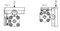
Formulas
Ma = F x ha
Mr = F x hr
Mv = F x hv
Deflection Graph
• Calculated deflections without support of 0.5 – 1 mm allow exceeding of supporting distance.
• Calculated deflections without support of 1mm – maximum 1.5 mm require reduction of the supporting distance.
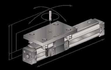
14.88
C A Ma Ma La L L C B A Lr L L Lr B Lr L L Lr D Mv Mv E G F H J Mr Mr RHV25/25 Fall 1 RHV25/25 Fall 2 RHV32/44 Fall 1 RHV32/44 Fall 2 RHV40/60 Fall 1 RHV40/60 Fall 2 m 3500 3000 2500 2000 1500 1000 500 0 0.3 0.5 0.7 0.9 1.1 1.3 1.5 1.7 1.9 2.1 2.3 2.5 F=N
L SL SL L SL F=N Load m Distance SL Distances SL of mounting with deflection 1 mm. R Series Page 394
RHV
14.89
RODLESS CYLINDER - CUSHIONED - MAGNETIC A D E F S H B C C M,N N1 M1 VS Z P WH VH G Q Q1 P1 W1 K U 2xA +STROKE ± 0,5 ØABCDEFGHKMN M1 N1 P P1 QxQ1 SU VH VS WS W1 Z 25 1009.523135120651/82.029.5M611M51074.056.836x368011272740226.5 32 1258.027180160961/42.037M814.5M61490.064.552x4811614.5403656328.0 40 1500302402161151/46.7539M816.5M617108.584.058.5x5913516.554546934.59.0 50 17522332402161151/41.039M816.5M618122.097.577x7813516.5707080315.0 R Series Page 395
SERIES RHL - RODLESS CYLINDERS - EXTERNALLY GUIDED
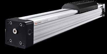
TECHNICAL CHARACTERISTICS Reference
Pressures
0.5 bar (0.05 MPa) / 7.3 psi
8 bar (0.8 MPa) / 116 psi
Functions
Rodless cylinder - double acting cushioned magnetic.
Advantages
Ability to accept high loads and moments in all directions.
• High tolerance to shock loads and vibrations.
Highly resistant to wear and corrosion.
Quiet running.
• Guiding elements are interchangable.
Temperatures - 10 °C / 14 °F + 80 °C / 176 °F
Media
Bar Bores from Ø 32 to Ø 63 mm
Filtered and lubricated or non-lubricated compressed air.
Standard Strokes
From 100 to 5700 mm
14.90
Standard 1907/2006 2011/65/CE PED 2014/68/UE SILICON FREE
032 032 040 050 063 Ø (mm) Series RHL Rodlesscylinder cushioned-magnetic RHL 0100 Stroke (mm)
Forces and Torque Cylinder Max. zul. Last L Max. L a, L r, L v Max. Ma Max. Mr Max. Mv N N Nm Nm Nm 32 760760391539 40 13301330993599 50 1600160017058170 63 27702770315105317
recommended DT Sensor adapter - 016 / 25 DSTR025 R Series Page 396
From100to5700mm
Sensors
Forces and Moments
1. The moments in the chart on the previous page (Ma max, Mr max, Mv max) relate to the guide rail center.
The load force L is the total of all single forces related to the common center of the mass.
The center of the mass can be placed inside or outside the surface area of the carriage.
2. Normally the carriage would experience a dynamic load which has to be considered with the needed piston force (F) and capacity of the ballguided system.
Use the following formula for calculations:
Deflection Graph
Calculated deflections without support of 0.5 – 1 mm allow exceeding of supporting distance.
Calculated deflections without support of 1mm – maximum 1.5 mm require reduction of the supporting distance.
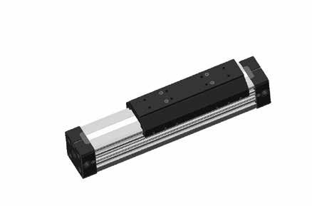
Formulas
Ma = F x ha
Mr = F x hr
Mv = F x hv
14.91 L Mv Ma Mr F ha y hr hv
C A Ma Ma La L L C B A Lr L L Lr B Lr L L Lr D Mv Mv E G F H J Mr Mr
F=N Load m Distance SL RHL32 RHL40 RHL50 RHL63 3000 2500 2000 1500 1000 500 0 0.3 0.5 0.7 0.9 1.1 1.3 1.5 1.7 1.9 2.1 2.3 2.5 F=N m L SL SL L SL
R Series Page 397
Distances SL of mounting with deflection 1 mm.
14.92
RODLESS CYLINDER - CUSHIONED - MAGNETIC S1 WH A B E E1 F S M, N WS W P1 H P Q1 Q K D M N L VH G ZV S M1,N1 M, N M, N M, N 2xA + STROKE ± 0,5 ØABCDE E1 FGHKLMN M1 N1 P P1 QxQ1 S S1 VH VS W WH WS Z 32 125222715260120251/42.042.510.5M510M61481.56.552x51664036403052568 40 15012.53021568160251/47.04415M810M61797.56.558.5x59794554543672699 50 17517.53325084190251/40.548.511.7M810M6181106.577x789250707043.580804 63 2156.555320120240253/81.55625M814M8181375.0102x10211650787862.510610614.5 R Series Page 398
RHL
14.93
RCP FOOT MOUNT Ø 16-25 mm RCP FOOT MOUNT Ø 32-63 mm RCN INTERMEDIATE SUPPORT BRACKET Ø 16-25 mm
INTERMEDIATE SUPPORT BRACKET Ø 32-63 mm B C A E F G H Part No. Ø A B C D E F G H RCP 016 16 1.518263.64.0141.512.5 RCP 025 25 2.527405.56.022218 B C P G E F H Code Ø B C D E F G H P RCP 032 32 36516,582442020 RCP 040 40 5471911,52422030 RCP 050 50 7080912,52512545 RCP 063 63 7810511153024048 J K L N O Part No. Ø J K L M N O RCN 016 16 41.553.55ø5.5203 RCN 025 25 48.5606ø5.5204 O A J K C Q N L M Part No. ØA C J K L M N O Q RCN 032 32 5208291304.545630 RCN 040 40 5209099254.5458.530 RCN 050 50 535123148356.545130 RCN 063 63 535147172356.5453.530 R Series Page 399
SERIES R ACCESSORIES
RCN
RCNN
RCOL
14.94
INTERMEDIATE SUPPORT BRACKET
RCNG
INTERMEDIATE SUPPORT BRACKET
ARTICULATED CARRIAGE AG EG MG PG LG FG KG DG JG GG CG BG Part No. Ø AG BG CG DG EG FG GG JG KG LG MGPG RCNG 016 16 18.030.027.518.421.015.0M411.513.929.019.710.8 RCNG 025 25 36.050.034.527.031.322.0M514.020.036.529.016.0 RCNG 032 32 36.050.041.834.239.030.0M614.027.647.039.521.5 AW BW EW MW PW LW FW HW KW JW GW DW CW Part No. Ø AW BW CW DW EW FW GW HW JW KW LW MW PW RCNN 016 16 18.030.037.032.521.015.0ø4.56.022.413.938.032.910.8 RCNN 025 25 36.050.047.540.031.322.0ø5.510.026.020.049.542.016.0 RCNN 032 32 36.050.056.047.539.030.0ø6.510.028.527.661.052.521.5 KA KE KY KC KH KJ KB KG KD KF Part No. Ø KA KB KD KE KF KG KH KJ KY RCOL 016 16 26M4101046.5-47.53.0282033 RCOL 025 25 38M5191671.5-73.53.5403051.5 RCOL 032 32 62M6282594.5-96.56.0604666.5 RCOL 040 40 62M62825108-1106.0604673.5 RCOL 050 50 90943.770135-1506.412010095-110 RCOL 063 63 90943.770155-1706.4120100102-117 R Series Page 400
TECHNICAL CHARACTERISTICS
SERIES XR - ROTARY ACTUATORS - ISO 15552

Male output shaft
Bar
Pressures
1 bar (0.1 MPa) / 14.5 psi
10 bar (0.7 MPa) / 145 psi
Temperatures 0 °C / 32 °F (-20 °C / -4 °F with dry air) + 80 °C / 176 °F
Media Filtered and lubricated or non-lubricated compressed air.
Functions
Double acting - cushioned - magnetic with male output shaft.
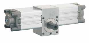
Double acting - cushioned - magnetic with female output shaft.
Bores from 32 to 100 mm
Torque at 1 bar
14.95
Ø mm Nm 32 1.2 40 2.25 50 3.9 63 7.3 80 15.7 100 26.35
angle Ø mm Standard Rotation 32 - 40 - 50 - 63 - 80 - 100 90°180°270°360°
Adjustable
Standard 1907/2006 2011/65/CE PED 2014/68/UE SILICON FREE ATEX 2014/34/UE Ø (mm) 032 040 050 063 080 100 0 32 Series XRM RotaryActuatorwithMale OutputShaftandAngle Adjustment+/-5º XRF RotaryActuatorwithFemale OutputShaftandAngle Adjustment+/-5º X RM Rotation 0 90 90° 180° 270° 360°
Reference
Series XR Page 401
Female output shaft
XRM
ROTARY ACTUATOR WITH MALE OUTPUT SHAFT AND ANGLE ADJUSTMENT +/- 5º
14.96
Y C H E G Q øP D N J T S A F R C X B K W Z 1 U V L1 Key UNI 6604-A DIN 6885/A L 2,5 C Rotation Ø mm 90° 180° 270° 360° L L1 L L1 L L1 L L1 32 232213279260326307373354 40 274254330310387367464424 50 301276364339427402489464 63 343320418395493470567544 80 416386515485614584713683 100 449418556525662631769738 Dimensions L and L1 for rotations. ØABCDEFGHJKNPQRSTUVWXYZ 32 71.55033461/8G46.52218M5254142525M59508125M6105 40 826040541/4G54.521.522M5304142530M510609125M6105 50 947050641/4G60.524.525M632.54193032.5M686510635M8136 63 1107560743/8G70.82635M837.54243037M8107511635M8138 80 1429980943/8G93.52650M849.54284550M9129915045M10168 100 156.5115801111/2G993060M1057.54385054M91711516645M101610 Series XR Page 402
XRF
ROTARY ACTUATOR WITH FEMALE OUTPUT SHAFT AND ANGLE ADJUSTMENT +/- 5º
14.97
C H E D N Q øP 1 T S A F R C J X Y B K U L1 L C V G Rotation Ø mm 90° 180° 270° 360° L L1 L L1 L L1 L L1 32 232213279260326307373354 40 274254330310387367464424 50 301276364339427402489464 63 343320418395493470567544 80 416386515485614584713683 100 449418556525662631769738 Dimensions L and L1 for rotations. ØABCDEFGHJKN ØP QRSTUVXY 32 71.55033461/8G46.522185254142525M595016.3M610 40 826040541/4G54.521.5225304142530M5106016.3M610 50 947050641/4G60.524.525632.54193032.5M686521.8M813 63 1107560743/8G70.82635637.54193037M8107521.8M813 80 1429980943/8G93.52650849.54244550M9129927.3M1016 100 156.5115801111/2G993060857.54285054M91711531.3M1016 Series XR Page 403
SwitchinglogicSPST.Normallyopen
SensortypeReedSwitch VoltageRange5÷240VDC/AC
Switchingcurrent100mAmax Contactrating10Wmax Maxvoltagedrop0.3V
OutputstatusindicatorREDLED
Operatingfrequency200Hz
Workingtemperature-10/+70°C 14/158°F
Shock30G
Vibration9G ProtectiondegreeIEC60529IP67 ProtectionCircuitNO
Switches
SERIES DT - MAGNETIC SWITCHES
Connectionø2.8-3WIRE
SwitchinglogicSolidStateOutput.Normallyopen SensortypePNPCurrentSourcing
VoltageRange10÷28VDC
Switchingcurrent80mAmax
Contactrating2Wmax
Maxvoltagedrop10mA@24VDCmax
Maxvoltagedrop1.5Vmax
Leakagecurrent0.05mAmax
OutputstatusindicatorRED/GREENLED
Operatingfrequency1000Hz
Magneticrequirement50Gauss
Workingtemperature-10/+60°C 14/140°F
Shock50G
Vibration9G
ProtectiondegreeIEC60529IP67
14.98
DT01 R M8 DT01 R 2M LED SENSING POINT BROWN (+) 1 4 3 BLUE (-) NOT USED 33 5 510 300±20 Part No. DT01 R 2M Part No. DT01 R M8
Connectionø2.8-2WIRE PU-2MT ø2.8-2WIRE PU-M8CONNECTOR
Quick Installation Common cylinder slot dimensions Common cylinder slot dimensions DT02 P M8 DT02 P 2M LED SENSING POINT BROWN (+) 1 4 3 BLACK (OUT) BLUE (-) 5 5 3 300±20 28 Unstable sensing range ON OFF SW OUT Unstable sensing range Stable sensing range R RG G Dual color LED allows more precise positioning. Part No. DT02 P 2M Part No. DT02 P M8
PU-2MT ø2.8-3WIRE PU-M8CONNECTOR
Page 404
Connectionø2.8-3WIRE
PU-2MT
SwitchinglogicSolidStateOutput.Normallyopen
SensortypePNPCurrentSourcing
VoltageRange10÷28VDC
Switchingcurrent200mAmax
Contactrating5.5Wmax
Maxvoltagedrop10mA@24VDCmax
Maxvoltagedrop1.5V@50mAmax
Leakagecurrent0.05mAmax
OutputstatusindicatorREDYELLOW
Operatingfrequency1000Hz
Magneticrequirement50Gauss
Workingtemperature-10/+70°C 14/158°F
Shock50G
Vibration9G
ProtectiondegreeIEC60529IP67
SERIES DTEX - ATEX SWITCHES
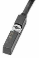
14.99
Part No.
DTEX03 P 2M
II 3GDEx ic IIB T4 Gc (-10°C ≤ Ta ≤ +70°C ) Ex ic IIB T135 °C Dc (-10°C ≤ Ta ≤ +70°C) DTEX03
SENSING POINT 5 5 2,3 Quick Installation Common cylinder slot dimensions Common cylinder slot dimensions Switches Page 405
CE ATEX APPROVAL (Baseefa14ATEX0118)
P 2M
SERIES DSL - MAGNETIC SWITCHES
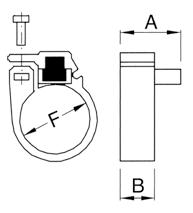

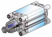
SwitchinglogicN.O.
SensortypeREEDREEDPNP-HALLPNP-HALL
VoltageRange3-130VAC/DC3-130VAC/DC10-30VDC10-30VDC
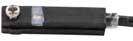
Maxcurrentat25°C(77°F)50mA50mA200mA200mA
Maxpower/Resistiveload10W10W6W6W
Maxvoltagedrop3.2V3.2V0.8V0.8V
OutputstatusindicatorYELLOWLED
Responsetime0.5msmax0.5msmax0.2msmax0.2msmax
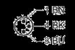
Decaytime0.1msmax
Electriclife(resistiveload)4x10
Workingtemperature-20/+70°C
ProtectiondegreeIP68
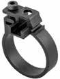
ShortcircuitNO

TypeofmountingtothecylinderLongitudinalonly

14.100
Common cylinder slot dimensions 5.4±0.3 3.4±0.3 Part No. DSL1 C 225 Part No. DSL1 M8 Part No. DSL4 N 225 Part No. DSL4 M8
Circuitdiagram
Connection
2WIRE PVC-2.5MT
2WIRE PVC-0.3MT-M8CONNECTOR
3WIRE PVC-2.5MT
3WIRE PVC-0.3MT-M8CONNECTOR
7
-4/158°F
DSL sensor lengthwise assembly.
Part No. Ø F = Ø AB MFX 008 8 9.4mm148 MFX 010 10 11.3mm148 MFX 012 12 13.3mm148 MFX 016 16 17.3mm148 MFX 020 20 21.3mm148 MFX 025 25 26.3mm148 Part No. Ø F = Ø AB AFX 032 32 33.5mm148 AFX 040 40 41.5mm148 AFX 050 50 52mm148 AFX 063 63 65mm148 Switches Page 406
BRACKET FOR DSL TO USE WITH MINI CYLINDERS ISO 6432 AND A95 SERIES CYLINDERS
SwitchinglogicN.O.
SensortypeREEDREEDPNP-HALLPNP-HALL
VoltageRange5-120VAC/DC5-120VAC/DC10-30VDC10-30VDC
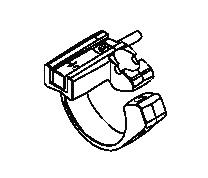
Maxcurrentat25°C(77°F)100mA
Maxpower/Resistiveload10W10W--
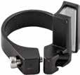
Maxvoltagedrop<5V<5V<2.5V<2.5V
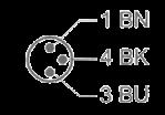
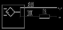
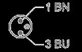
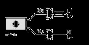
OutputstatusindicatorYELLOWLED
Responsetime0.5msmax0.5msmax-Decaytime0.1msmax0.1msmax<30ms<30ms
14.101
Part No. DSH2 R 2F 20 Part No. DSH2 R 2F M8 Part No. DSH4 H 3F 20 Part No. DSH4 H 3F M8
SERIES DSH - MAGNETIC SWITCHES
Circuitdiagram
Connection
2WIRE PVC-2MT
2WIRE PVC-0.3MT-M8CONNECTOR
3WIRE PUR-2MT
3WIRE PUR-0.3MT-M8CONNECTOR
Electriclife(resistiveload)107107INFINITEINFINITE Workingtemperature-20/+70°C -4/158°F -25/+85°C -13/185°F ProtectiondegreeIP67 ShortcircuitNO TypeofmountingtothecylinderAxialandlongitudinal Common cylinder slot dimensions 5.4±0.3 3.4±0.3
DSH sensors with axial or longitudinal inserting slot.
Part No. Ø F = Ø MFH 012 12 13.3mm MFH 016 16 17.3mm MFH 020 20 21.3mm MFH 025 25 26.3mm
Page 407
BRACKET FOR DSH TO USE WITH MINI CYLINDERS ISO 6432
Switches
BRACKET FOR CYLINDERS WITH TIE RODS
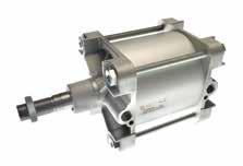
EXF
BRACKET FOR DSL - DSH - DT SENSORS Part No. Ø A
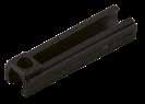
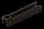
EXF032 32-407,5252
EXF050 50-6311,3252,5
EXF080 80-100-12515,3252,5
EXF160 160-200-25020252,5
EXTENSION MAGNETIC FOR SWITCHES
EXF
BRACKET FOR DSL - DSH - DT SENSORS

Circuitdiagram
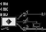
14.102
DC
00 001 DC 10 001
SENSOR DC ADAPTER DC
B C
Part No. Lunghezza - Length - Länge - Longueur - Longitud - Comprimento PX 2000 PUR 2MT PX 5000 PUR 5MT
Switches Page 408
SENSOR DC ADAPTER
Directive 2014/34/UE (ATEX)

The Pneumatic Cylinders: Cartridge, Mini Cylinders ISO 6432, Stainless steel Mini Cylinders, A95, Compact (Q - W), Short Stroke (B), Series X ISO 15552, Series E ISO 6431, Twin-piston rod Series NHA ISO 15552 and Series P ISO 15552 show the following features:
II 2 GD c T6 -20°C<Tamb<80°C
II 2 GD: Device for surface installations (II = do not use device in mining) with presence of gas, vapors of powders of category 2 (equipment with high safety factor since it excludes danger of explosion, even in case of damage; it can be used in areas with possible explosive environments).
c: Devices are constructively safe
T6 – 10ºC<Tamb<60ºC: Surface temperature class and additional marking for T usage environment.
14.103
See Instructions and Certificate at: WWW.AIGNEP.COM
Page 409
Switches
14.104 NOTES Switches Page 410
Mini FRL Series


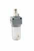


Evo Series


Aignep si riserva il diritto di variare modelli e ingombri senza preavvisoAignep reserves the right to vary models and dimensions without noticeAignep behält sich das Recht vor, Daten ohne Ankündi gung zu ändern


Aignep se réserve le droit de modifier les données sans préavisAignep se reserva el derecho de modificar modelos y dimensio nes sin previo avisoAignep reserva-se o direito de alterar os modelos e dimensões sem prévio aviso

N010 Mini Pag. 15.4 N015 Mini Pag. 15.6 N020 Mini Pag. 15.8 N070 Mini Pag. 15.10 N080 Mini Pag. 15.12 N030 Mini Pag. 15.14 N040 Mini Pag. 15.16 N100 Mini Pag. 15.18 N400 Mini Pag. 15.20 Accessories Pag. 15.22
N010 Pag. 15.29 N015 Pag. 15.31 N020 Pag. 15.33 N030 Pag. 20.37 N040 Pag. 15.39 N100 Pag. 15.51 N050 Pag. 15.41 N060 Pag. 15.47 N400 Pag. 15.53 N025 Pag. 15.35 N051 Pag. 15.43 N052 Pag. 15.45 Accessories Pag. 15.55 N090 Pag. 15.49 Page 411
FRL
AIR TREATMENT UNIT
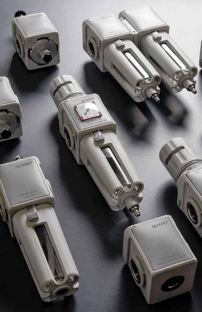
FRL Series
FRL Page 412
Mini technical instruction
The FRL components must be assembled in the following order: Filter, Regulator, Lubricator.
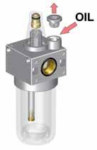
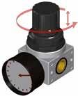
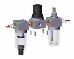
While connecting the components, be sure that the air flows towards the direction of the arrows located on the upper surface of the components
Assembling and Setting pressure
1 To set up each component, follow these steps:
- Line the plates up with the bodies.
- Assemble parts together, making sure that the o-ring seals are in their proper seats.
- Tighten the screws on the plates.
2 To regulate the pressure, follow these instructions:
- Turn the knob to the desired pressure.
- Rotate the knob to increase or decrease the pressure.
- Press the knob to the block position.
The pressure gauge has to be assembled manually with the addition of liquid sealant.
The mini quick exhaust regulator allows the circuit downstream to exhaust rapidly when upstream pressure is interrupted.
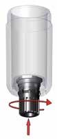
Mini technical instruction
1 The manual/semiautomatic condensation exhaust is normaly in the open position; i.e. it automatically exhausts the condensation when there is no pressure inside the bowl. Pressing the knob will exhaust the condensation even if there is pressure. Turning the knob counterclockwise will close off the exhaust.
2 To add oil to the lubricator, unscrew the plug located on the upper surface or disassemble the bowl. Make sure that there is no pressure in the system before adding oil or disassembling the bowl.
3 To remove the bowl, use CH3 caliper face spanners. The transparent bowl shows the condensation level in the filter and the oil level in the lubricator.
15.3 Mini FRL Series 2 CH3
2 2 Page 413
N010 MINI FILT ER
Component Parts and Materials
2 0 1 003 000 N100

15.4 Mini FRL Series
02 = 1/8 NPTF 03 = 1/4 NPTF 1 = 5 µm 2 = 20 µm 3 = 50 µm 1 = Semiautomatic Manual Series Thread
Filtration Grade Condensate exhaust System
System
Part Numbering
FLUID Compressed Air THREAD 1/8" NPTF 1/4" NPTF FILTRATION GRADE 5 µm 20 µm STANDARD 50 µm 6 bar FLOW RATE with ∆p 1 bar 800 NI/min Bar MAX PRESSURE 15 bar (217 psi) TEMPERATURE -10 °C (14 F) + 50 °C (122 F) ASSEMBLY POSITION Vertical BOWL CAPACITY 17.5 cm3 CONDENSATION EXHAUST Manual Semi Automatic Reference standard 1907/2006 2011/65/CE PED 2014/68/UE
TECHNICAL CHARACTERISTICS
Technopolymeric Body
Brass Threaded insert 3 Technopolymeric Bowl 4 Technopolymeric Filter ring 5 Technopolymeric Condensate exhaust 6 PE Filtering cartridge 7 Technopolymeric Slinger 8 NBR O-Ring 1 2 8 7 5 6 4 3 Page 414
1
2
15.5 Mini FRL Series N010 Dimensions B H K L J D E F W C Q B C D E F H I J K L W Q 109 404013.52011273010 Ø X M31/8 - 1/4 1/8 Part Number Size Thread (NPTF) Filtration Flow Rate (NPTF) N010 002 201 000 FIL 0 1/8 20 µm 800 Nl/min N010 003 201 000 FIL 0 1/4 20 µm 800 Nl/min Page 415
N015 MINI COAL ESCER FILTER
15.6 Mini FRL Series
CHARACTERISTICS Reference standard 1907/2006 2011/65/CE PED 2014/68/UE FLUID 5 µm Filtred Compressed Air THREAD 1/8" NPTF 1/4" NPTF FILTRATION GRADE 0.01 µm 6 bar FLOW RATE with ∆p 1 bar 450 NI/min Bar MAX PRESSURE 15 bar (217 psi) TEMPERATURE -10 °C (14 F) + 50 °C (122 F) ASSEMBLY POSITION Vertical BOWL CAPACITY 17.5 cm3 CONDENSATION EXHAUST Manual Semi Automatic
TECHNICAL
1 Technopolymeric Body 2 Brass Threaded insert 3 Technopolymeric Bowl 4 Technopolymeric Condensate exhaust 5 Coalescer cartridge 6 NBR O-Ring Part Numbering System 02 = 1/8 NPTF 03 = 1/4 NPTF 4 = 0.01 µm 1 = Semiautomatic Manual Series Thread 4 0 1 003 000 N105 Filtration Grade Condensate exhaust System Page 416
Component Parts and Materials
N015 Mini
15.7 Mini FRL Series
Dimensions B H K L J D I E F W C Q B C D E F H I J K L W Q 109 404013.52011273010 Ø X M31/8 - 1/4 1/8 NB: With Coalescer filter T015 we recommend to install a 5 µm Filter upstream.. Part Number Size Thread (NPTF) Filtration Flow Rate (NPTF) N015 002 401 000 FC 0 1/8 0.01 µm 450 Nl/min N015 003 401 000 FC 0 1/4 0.01 µm 450 Nl/min Page 417
N020 MINI REGU LATOR
TECHNICAL
Component Parts and Materials
1 Technopolymeric Boby
2 Technopolymeric Bell
3 Technopolymeric Fixing nut
4 Technopolymeric Knob
5 Brass Register screw
6 Brass Female screw
7 Steel Register spring
8 Membrane Rolling
9 NBR Relieving diaphragm
10 Shutter with NBR vulcanized seal
11 Technopolymeric Plug
12 Stainless steel Push-shutter spring
13 NBR O-Ring
14 Brass Threaded insert
15.8 Mini FRL Series
CHARACTERISTICS Reference standard 1907/2006 2011/65/CE PED 2014/68/UE FLUID Compressed Air THREAD 1/8" NPTF 1/4" NPTF FILTRATION GRADE 0-29 psi 0-58 psi 0-116 psi (standard) 0-174 psi 6 bar FLOW RATE with ∆p 1 bar 600 NI/min Bar MAX PRESSURE 15 bar (217 psi) TEMPERATURE -10 °C (14 F) + 50 °C (122 F ASSEMBLY POSITION Vertical GAUGE THREAD G 1/8
Numbering System 02 = 1/8 NPTF 03 = 1/4 NPTF 1 =0-29 psi 2 =0-58 psi 3 =0-116 psi (standard) 4 =0-174 psi Series Thread 0
N200 Regulation range 7 5 8 1 6 3 4 2 9 10 11 12 13 14 Page 418
Part
3 0 003 000
15.9 Mini FRL Series
Dimensions F B C M G E D W B C D E F G I M W 74 40 40 13.5 20 27.5 27M30X1.5 1/8 - 1/4 Part Number Size Thread (NPTF) Regulation Flow Rate (NPTF) N020 002 030 000 REG 0 1/8 0-116 psi 600 Nl/min N020 003 030 000 REG 0 1/4 0-116 psi 600 Nl/min Page 419
N020 Mini
N070 MINI QUIC K EXHAUST REGULATOR
15.10 Mini FRL Series
TECHNICAL CHARACTERISTICS Reference standard 1907/2006 2011/65/CE PED 2014/68/UE FLUID Compressed Air THREAD 1/8" NPTF 1/4" NPTF FILTRATION GRADE 0-29 psi 0-58 psi 0-116 psi (standard) 0-174 psi 6 bar FLOW RATE with ∆p 1 bar 600 NI/min Bar MAX PRESSURE 15 bar (217 psi) TEMPERATURE -10 °C (14 F) + 50 °C (122 F ASSEMBLY POSITION Vertical GAUGE THREAD G 1/8
1 Technopolymeric Boby 2 Technopolymeric Bell 3 Technopolymeric Fixing nut 4 Technopolymeric Knob 5 Brass Register screw 6 Brass Female screw 7 Steel Register spring 8 Membrane Rolling 9 NBR Relieving diaphragm 10 Shutter with NBR vulcanized seal 11 Technopolymeric Plug 12 Stainless steel Push-shutter spring 13 NBR O-Ring 14 Brass Threaded insert 7 5 8 1 6 3 4 2 9 10 11 12 13 14 Part Numbering System 02 = 1/8 NPTF 03 = 1/4 NPTF 1 =0-29 psi 2 =0-58 psi 3 =0-116 psi (standard) 4 =0-174 psi Series Thread 0 3 0 003 000 N700 Regulation range Page 420
Component Parts and Materials
15.11 Mini FRL Series
Dimensions F B C M G E D W B C D E F G I M W 74 40 40 13.5 20 27.5 27M30X1.5 1/8 - 1/4 Part Number Size Thread (NPTF) Regulation Flow Rate (NPTF) N070 002 030 000 REG. 0 1/8 0-116 psi 600 Nl/min N070 003 030 000 REG. 0 1/4 0-116 psi 600 Nl/min Page 421
N070 Mini
N080 MINI
TECHNICAL CHARACTERISTICS
Food grade approved version also available.
Component Parts and Materials
1
2
3
4
7
10
WATE R REGULATOR
Part Numbering System
15.12 Mini FRL Series
Reference standard 1907/2006 2011/65/CE PED 2014/68/UE FLUID Water THREAD 1/8" NPTF 1/4" NPTF FILTRATION GRADE 0-29 psi 0-58 psi 0-116 psi (standard) 0-174 psi Bar MAX PRESSURE 15 bar (217 psi) TEMPERATURE + 5 °C (41 F) + 50 °C (122 F ASSEMBLY POSITION Vertical GAUGE THREAD G 1/8 7 2 9 10 11 12 13
Technopolymeric Boby
Technopolymeric
Bell
Technopolymeric Fixing nut
Technopolymeric
Knob
5 Brass Register screw
6 Brass Female screw
Steel Register spring
Membrane
Shutter with NBR vulcanized seal
8
Rolling 9
Technopolymeric
Plug
11 Stainless steel Push-shutter spring
12 NBR O-Ring
13 Brass Threaded insert
02 = 1/8 NPTF 03 = 1/4 NPTF 1 =0-29 psi 2 =0-58 psi 3 =0-116 psi (standard) 4 =0-174 psi Series Thread 0 3
N800 Regulation range Page 422
0 003 000
15.13 Mini FRL Series
Dimensions F B C M G E D W B C D E F G I M W 74 40 40 13.5 20 27.5 27M30X1.5 1/8 - 1/4 Part Number Size Thread (NPTF) Regulation N080 002 030 000 WATER REG. 0 1/8 0-116 psi N080 003 030 000 WATER REG. 0 1/4 0-116 psi Page 423
N080 Mini
N030 MINI FILT ER REGULATOR
15.14 Mini FRL Series
02 = 1/8 NPTF 03 = 1/4 NPTF 1 = 5 µm 2 = 20 µm 3 = 50 µm 1 = Semiautomatic Manual 1 =0-29 psi 2 =0-58 psi 3 =0-116 psi (standard) 4 =0-174 psi Series Thread
Filtration Grade Condensate exhaust System Regulation Range TECHNICAL CHARACTERISTICS Reference standard 1907/2006 2011/65/CE PED 2014/68/UE FLUID Compressed Air THREAD 1/8" NPTF 1/4" NPTF REGULATION RANGE 0-29 psi 0-58 psi 0-116 psi (standard) 0-174 psi FILTRATION GRADE 5 µm 20 µm STANDARD 50 µm 6 bar FLOW RATE with ∆p 1 bar 600 NI/min Bar MAX PRESSURE 15 bar (217 psi) TEMPERATURE + 5 °C (41 F) + 50 °C (122 F ASSEMBLY POSITION Vertical BOWL CAPACITY 17.5 cm3 CONDENSATION EXHAUST Manual Semi Automatic GAUGE THREAD G 1/8 Component Parts and Materials 1 Technopolymeric Body 2 Technopolymeric Bell 3 Technopolymeric Fixing nut 4 Technopolymeric Knob 5 Brass Register screw 6 Brass Female screw 7 Register spring made in steel 8 Rolling membrane 9 NBR Relieving diaphragm 10 Shutter with NBR vulcanized seal 11 Technopolymeric Filter ring 12 Technopolymeric Bowl 13 Technopolymeric Condensate exhaust 14 PE Filtering cartridge 15 Technopolymeric Slinger 16 NBR O-Ring 17 Brass Threaded insert Part Numbering System 54 6 2 3 7 8 1 9 10 11 12 13 14 15 16 17 Page 424
231 003 000 N300
15.15 Mini FRL Series
Dimensions B E D G M C W N F H Q B C D E F G H I M N W 156 M30X1.54013.52027.511274040 1/8 - 1/4 Part Number Size Thread (NPTF) Filtration Regulation Flow Rate (NPTF) N030 002 231 000 FR 0 1/8 20µm 0-116 psi 600 Nl/min N030 003 231 000 FR 0 1/4 20µm 0-116 psi 600 Nl/min Page 425
N030 Mini
N040 MINI LUBR ICATOR
Component Parts and Materials
1 Technopolymeric Body
2 Technopolymeric Bowl
3 Brass Threaded insert
4 Membrane Venturi device
5 Oil aspiration tube made in PA11
6 Small filter
7 Trasparent technopolymeric Visual dome
8 Brass Oil regulating capacity pin
9 Brass Oil loading plug
10 Brass Air diffuser
11 NBR O-Ring
002 100 000 N400
15.16 Mini FRL Series
02 = 1/8 NPTF 03 = 1/4 NPTF 1 = Manual Series Thread
Oil loading System TECHNICAL CHARACTERISTICS Reference standard 1907/2006 2011/65/CE PED 2014/68/UE FLUID Compressed Air THREAD 1/8" NPTF 1/4" NPTF 6 bar FLOW RATE with ∆p 1 bar 700 NI/min Bar MAX PRESSURE 15 bar (217 psi) TEMPERATURE -10 °C (14 F) + 50 °C (122 F WALL CLAMPING SCREWS M3 ASSEMBLY POSITION Vertical BOWL CAPACITY 28 cm3 RECOMMENDED OILS ISO VG 22A CLASS ISO 3448 NORMA
Numbering System 1 7 4 10 2 5 6 8 9 3 11
Part
Page 426
15.17 Mini FRL Series N040 Mini Dimensions D J C W L F B H E K IM B C D E F H I J K L M W 130 404013.52011273010 Ø X M3 33.5 1/8 - 1/4 Part Number Size Thread (NPTF) Flow Rate (NPTF) N040 002 000 100 LUB 0 1/8 700 Nl/min N040 003 000 100 LUB 0 1/4 700 Nl/min Page 427
N100 MINI FILT ER REGULATOR + LUBRICATOR
15.18 Mini FRL Series
02 = 1/8 NPTF 03 = 1/4 NPTF 1 = 5 µm 2 = 20 µm 3 = 50 µm 1 = Semiautomatic Manual 1 = Manual 1 =0-29 psi 2 =0-58 psi 3 =0-116 psi (standard) 4 =0-174 psi Series Thread 231 003
Filtration Grade Condensate exhaust System Oil loading System Regulation Range TECHNICAL CHARACTERISTICS Reference standard 1907/2006 2011/65/CE PED 2014/68/UE Part Numbering System FLUID Compressed Air THREAD 1/8" NPTF 1/4" NPTF FILTRATION GRADE 5 µm 20 µm STANDARD 50 µm REGULATION RANGE 0-29 psi 0-58 psi 0-116 psi (standard) 0-174 psi 6 bar FLOW RATE with ∆p 1 bar 260 NI/min Bar MAX PRESSURE 15 bar (217 psi) TEMPERATURE -10 °C (14 F) + 50 °C (122 F WALL CLAMPING SCREWS M3 ASSEMBLY POSITION Vertical BOWL CAPACITY 28 cm3 RECOMMENDED OILS ISO VG 22A CLASS ISO 3448 NORMA Page 428
100 N010
N100 Mini
15.19 Mini FRL Series
Dimensions J L N B D C W K B C D I J K L N W 156 40 80 27 30 10 Ø X M3 40 1/8 - 1/4 Part Number Size Thread (NPTF) Filtration Regulation Flow Rate (NPTF) N100 002 231 100 FR+L 0 1/8 20µm 0-116 psi 260 Nl/min N100 003 231 100 FR+L 0 1/4 20µm 0-116 psi 260 Nl/min Page 429
N400 MINI FILT ER + FILTER COALESSER
Part Numbering System
4 0 1 003 000 N040
15.20 Mini FRL Series
02 = 1/8 NPTF 03 = 1/4 NPTF 4 = 0.01 µm 1 = Semiautomatic Manual Series Thread
Filtration Grade Condensate exhaust System TECHNICAL CHARACTERISTICS Reference standard 1907/2006 2011/65/CE PED 2014/68/UE FLUID Compressed Air THREAD 1/8" NPTF 1/4" NPTF FILTRATION GRADE 5 µm + 0.01 µm 6 bar FLOW RATE with ∆p 1 bar 370 NI/min Bar MAX PRESSURE 15 bar (217 psi) TEMPERATURE -10 °C (14 F) + 50 °C (122 F WALL CLAMPING SCREWS M3 ASSEMBLY POSITION Vertical
Page 430
Information
Coalescer cartridge is made of a microfiber inner layer with an external stainless steel structure.
The coalescing cartridge uses inertial impact, interception and coalescense to collect excess liquid. This liquid will then drain into the bottom of the bowl.
The coalescing filter is used as oil separator which removes oil-vapours from the air output.
We recommend installing a 5 μm filter upstream to protect coalescing filter from choking the cartridge.
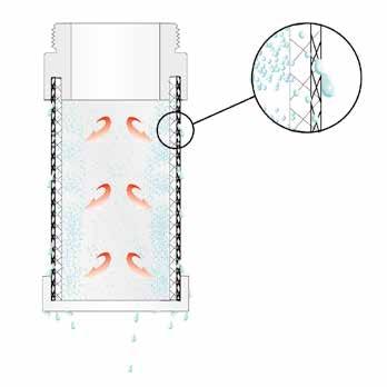
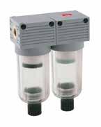
N400 Mini
COALESCER CARTRIDGE
15.21 Mini FRL Series
Dimensions J L B I D C W K B C D I J K L W 109 40 80 27 30 10 Ø X M31/8 - 1/4 Part Number Size Thread (NPTF) Filtration Flow Rate (NPTF) N400 002 401 000 FIL+FC 0 1/8 5µm + 0.01µm 370 Nl/min N400 003 401 000 FIL+FC 0 1/4 5µm + 0.01µm 370 Nl/min
INTERLACED MICROFIBERS
Page 431
BOWL FOR FILTER UNIT
T530
BOWL FOR LUBRICATOR UNIT T545
COALESCER FILTER
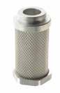

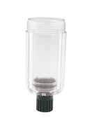
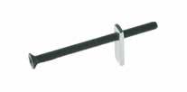
15.22 Mini FRL Series
T500 T520
Part Number T500 000 000 000 FRL 0 Part Number T520 000 001 000 FRL 0 Part Number T530 000 000 100 FRL 0 Part Number T545 000 000 000 FRL 0 FRL ACCESSORIES Page 432

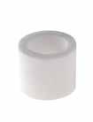
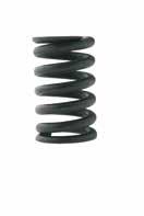
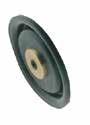
15.23 Mini FRL Series DIS00 AIR DISTRIBUTOR FIL04 SINTERED FILTER REG06 REGISTER SPRING REG09 MEMBRANE Part Number ABCD DIS00 001 100 NE FRL 0 27401/830 A G1/4 B Part Number FIL04 003 805 SC FRL 0 5 μm FIL04 003 820 SC FRL 0 20 μm FIL04 003 850 SC FRL 0 50 μm Part Number REG06 005 401 SC FRL 0 0-29 psi REG06 005 402 SC FRL 0 0-58 psi REG06 005 403 SC FRL 0 0-116 psi (standard) REG06 005 404 SC FRL 0 0-174 psi Part Number REG09 001 700 SC FRL 0 Page 433

15.24 Mini FRL Series REG16 CLAMP BRACKET SOL01 SOLENOID COIL Part Number ABCDF REG16 005 000 NE FRL 0 21.55.5121531 E A C D B See Cap. Valves 13 - page 13.20 Page 434
TECHNICAL CHARACTERISTICS FRL 1-2
Basic Assembly
The “FRL Evo” line is modular and the connection between each unit is simplified thanks to the connection brackets. The assembly of the modules may change according to individual use. To operate, make sure the shut off valve is in the first position and the soft start valve is in the last. There is an arrow on every unit to indicate the correct direction of air flow.
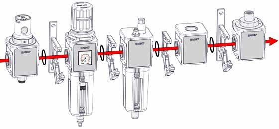
Mounting Instructions
Two mounting brackets are available for the FRL Evo Series to give the end user 2 different mounting options.
Removing the Bowl
To release to bowl, press down the button with the arrow and rotate the bowl clock-wise as shown in the drawing, then pull downward. The windows in the bowl allow you to view the level of condensation in the filter, or the amount of oil in the lubricator.
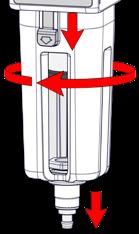
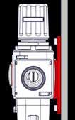
15.25 Evo FRL Series Y501 REG16 1 2 3
Page 435
Shut Off Valves
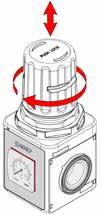
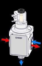
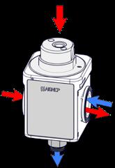
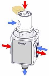
3 versios of the Shut Off Valves are available: Manual with lock and anti-tampering system, pneumatic and electro-pneumatic.
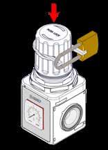
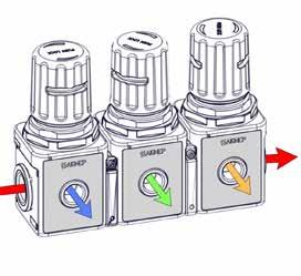
Regulators
Regulators are available with a built-in manometer or without. The adjustor knobs can lock into place and come with an anti-tampering system. Assembly kits for 1/8” manometer are available upon request.
Regulators
Regulators can be assebled together. Whether they have the built-in manometer or not, they all can be connected.
15.26 Evo FRL Series
Page 436
Regulators
Several options of manometers and pressure switches are available. Manometers and pressure switches can be inverted if desired.
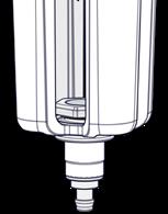
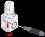
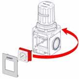
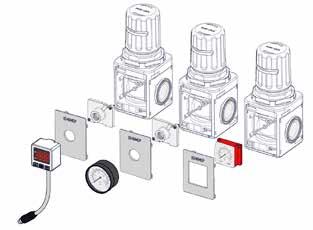
Condensation Drains
The condensation drain is available in 2 options, with vacuum or automatic with float.
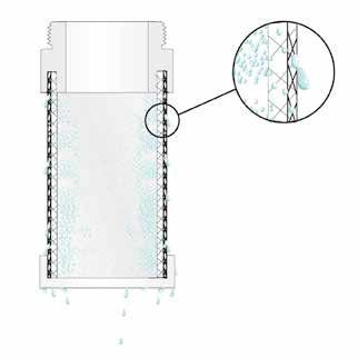
Coalescer Filter
20 μm, 5 μm filters and 0.01 μm coalescer filter.
COALESCER CARTRIDGE
INTERLACED MICROFIBERS
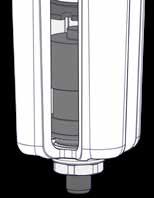
15.27 Evo FRL Series
Page 437
Lubricators
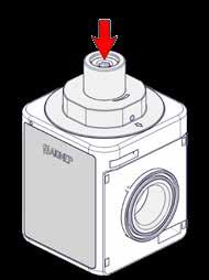
The lubricator unit is available in 2 options, with manual loading or with automatic vacuum-operated loading.
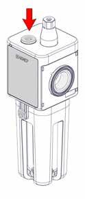
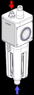
15.28 Evo FRL Series
Page 438
Soft Start Valve Soft start valve with adjustment screw.
N010 FILTER
TECHNICAL CHARACTERISTICS
013 000 N100
15.29 Evo FRL Series
FRL 1 FRL 2 METALLIC THREAD 1/4" NPTF 3/8" NPTF 3/8" NPTF 1/2" NPTF TORQUE SPECIFICATIONS Max 15 Nm Max 20 Nm 6 bar FLOW RATE with ∆p 1 bar 2500 NI/min 4100 NI/min MOUNTING SCREWS M5 x 15 BOWL CAPACITY 28 cm3 37 cm3 FILTRATION GRADE 5 µm 20 µm STANDARD FLUID Compressed Air Bar MAX PRESSURE 18 bar (260 PSI) TEMPERATURE -10 °C (14 F) + 50 °C (122 F) MOUNTING POSITION Vertical Series Thread Filtration Grade Condensate exhaust System Part Numbering System 1 = 5 µm 2 = 20 µm 1 = Vacuum-operated 2 = Automatic with float (max 8 bar)(116 PSI) 1 0 1
03 = 1/4 NPTF 04 = 3/8 NPTF 04 = 3/8 NPTF 05 = 1/2 NPTF FRL 1 FRL 2 Size Reference standard 1907/2006 2011/65/CE PED 2014/68/UE | | 2GD Ex h TX Page 439
Condensation Drain
DEP: The vacuum-operated condensation drain is normally in the open position. It automatically drains the condensation when there is no pressure in the bowl. By pressing the hose connector, the condensation will be pressurize and will drain.
A: The automatic condensation drain with float drains the condensation when the maximum level is reached independently from the air pressure.
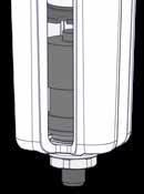
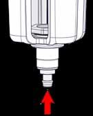
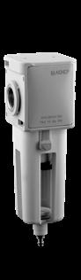
15.30 Evo FRL Series
Dimensions - FRL 1 Dimensions - FRL 2 A I C F W E R Y Q H B D A B C D W E F H I Q R T 51 1765157 1/4 - 3/8 32.525.511947.5 E.D .256 (6.5) 1447 A B C D W E F H I Q R T 62 197.56368 3/8 - 1/2 3931.5129.559 E.D .256 (6.5) 158.59.5 Part Number Size Thread (NPTF) Filtration Flow Rate Exhaust N010 103 201 000 FIL 1 1/4 20 µm 2500 Nl/min DEP N010 104 201 000 FIL 1 3/8 20 µm 2500 Nl/min DEP N010 104 202 000 FIL 1 3/8 20 µm 2500 Nl/min A N010 204 201 000 FIL 2 3/8 20 µm 4100 Nl/min DEP N010 205 201 000 FIL 2 1/2 20 µm 4100 Nl/min DEP N010 205 202 000 FIL 2 1/2 20 µm 4100 Nl/min A
N010
DEP A
Page 440
DEP = Vacuum-operated A = Automatic
N015
TECHNICAL CHARACTERISTICS
COALES CER FILTER
013 000 N105
15.31 Evo FRL Series
FRL 1 FRL 2 METALLIC THREAD 1/4" NPTF 3/8" NPTF 3/8" NPTF 1/2" NPTF TORQUE SPECIFICATIONS Max 15 Nm Max 20 Nm 6 bar FLOW RATE with ∆p 1 bar 800 NI/min 850 NI/min MOUNTING SCREWS M5 x 15 BOWL CAPACITY 28 cm3 37 cm3 FILTRATION GRADE 0.01 µm FLUID 5 µm filtred Compressed Air Bar MAX PRESSURE 18 bar (260 PSI) TEMPERATURE -10 °C (14 F) + 50 °C (122 F) MOUNTING POSITION Vertical Series Thread Filtration Grade Condensate exhaust System Part Numbering System 1 = 0.01 µm 1 = Vacuum-operated 2 = Automatic with float (max 8 bar) (116 PSI)
0
03 = 1/4 NPTF 04 = 3/8 NPTF 04 = 3/8 NPTF 05 = 1/2 NPTF FRL 1 FRL 2 Size Reference standard 1907/2006 2011/65/CE PED 2014/68/UE | | 2GD Ex h TX Page 441
4
1
Condensation Drain
DEP: The vacuum-operated condensation drain is normally in the open position. It automatically drains the condensation when there is no pressure in the bowl. By pressing the hose connector, the condensation will be pressurize and will drain.
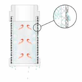
A: The automatic condensation drain with float drains the condensation when the maximum level is reached independently from the air pressure.
Coalescer Cartridge
The coalescer cartridge is made of a microfiber layer with an external stainless steel structure. The coalescer cartridge uses inertial impact, interception and coalescense to form liquid particles into drops. These drops will fall into the bottom of the bowl. The coalescer filter is used as an oil separator which removes oil-vapours from the air output. We recommend installing a 5 μm filter upstream to protect the coalescing filter from choking the cartridge.
15.32 Evo FRL Series N015 Dimensions - FRL 1 Dimensions - FRL 2 A C F W E R Y Q H B D A B C D W E F H I Q R Y 51 1765157 1/4 - 3/8 32.525.511947.5 E.D .256 (6.5) 1447 A B C D W E F H I Q R Y 62 197.56368 3/8 - 1/2 3931.5129.559 E.D .256 (6.5) 158.59.5 Part Number Size Thread (NPTF) Filtration Flow Rate Exhaust N015 103 401 000 FC 1 1/4 0.01 µm 800 Nl/min DEP N015 104 401 000 FC 1 3/8 0.01 µm 800 Nl/min DEP N015 104 402 000 FC 1 3/8 0.01 µm 800 Nl/min A N015 204 401 000 FC 2 3/8 0.01 µm 850 Nl/min DEP N015 205 401 000 FC 2 1/2 0.01 µm 850 Nl/min DEP N015 205 402 000 FC 2 1/2 0.01 µm 850 Nl/min A
COALESCER CARTRIDGE INTERLACED MICROFIBERS
NB: With Coalescer Filter Series N015, we recommend installing a 5 μm Filter upstream. DEP = Vacuum-operated
DEP A Page 442
N020 REGULATOR
TECHNICAL CHARACTERISTICS
0 1 0 013 000 N200
15.33 Evo FRL Series
FRL 1 FRL 2 METALLIC THREAD 1/4" NPTF 3/8" NPTF 3/8" NPTF 1/2" NPTF TORQUE SPECIFICATIONS Max 15 Nm Max 20 Nm 6 bar FLOW RATE with ∆p 1 bar 2700 NI/min 3500 NI/min MOUNTING SCREWS M5 x 15 REGULATION RANGE 0 ÷ 2 bar (29 PSI) 0 ÷ 4 bar (58 PSI) 0 ÷ 8 bar STANDARD (116 PSI) 0 ÷ 12 bar (174 PSI) FLUID Compressed Air Bar MAX PRESSURE 18 bar (260 PSI) TEMPERATURE -10 °C (14 F) + 50 °C (122 F) MOUNTING POSITION Vertical Series Thread Regulation Range Part Numbering System
03 = 1/4 NPTF 04 = 3/8 NPTF 04 = 3/8 NPTF 05 = 1/2 NPTF FRL 1 FRL 2 Size 1 = 0÷2 bar (29 PSI) 2 = 0÷4 bar (58 PSI) 3 = 0÷8 bar (116 PSI) 4 = 0÷12 bar (174 PSI) 1 = Manometer incorporated 2 = Adapter for manometer 1/8 NPTF (Manometer not included) Manometer system Reference standard 1907/2006 2011/65/CE PED 2014/68/UE | | 2GD Ex h TX Page 443
Regulating the Air Pressure
Follow the instructions below to set the air pressure:
1 Raise the knob to the regulating position.
2 Rotate to set the desired pressure, always in ascending order.
3 Press the knob down to lock into position. The knob can be padlocked to prevent tampering.
15.34 Evo FRL Series
Dimensions - FRL 1 Dimensions - FRL 2 A I M B Z D C F W E R A B C D W E F I R M Z 51 1175757 1/4 - 3/8 32.525.547.528 M37 x 1.5 57 A B C D W E F I R M Z 62 141.56768 3/8 - 1/2 3931.55933 M37 x 1.5 72.5 Part Number Size Thread (NPTF) Regulation Flow Rate N020 103 030 000 REG 1 1/4 0 ÷ 8 bar (116 PSI) 2700 Nl/min N020 104 030 000 REG 1 3/8 0 ÷ 8 bar (116 PSI) 2700 Nl/min N020 204 030 000 REG 2 3/8 0 ÷ 8 bar (116 PSI) 3500 Nl/min N020 205 030 000 REG 2 1/2 0 ÷ 8 bar (116 PSI) 3500 Nl/min
N020
Page 444
N025
TECHNICAL CHARACTERISTICS
FRON TAL REGULATOR
Part Numbering System 0 1 0 013 000 N205
15.35 Evo FRL Series
FRL 1 FRL 2 METALLIC THREAD 1/4" NPTF 3/8" NPTF 3/8" NPTF 1/2" NPTF TORQUE SPECIFICATIONS Max 15 Nm Max 20 Nm 6 bar FLOW RATE with ∆p 1 bar 2700 NI/min 3500 NI/min MOUNTING SCREWS M5 x 15 REGULATION RANGE 0 ÷ 2 bar (29 PSI) 0 ÷ 4 bar (58 PSI) 0 ÷ 8 bar STANDARD (116 PSI) 0 ÷ 12 bar (174 PSI) FLUID Compressed Air Bar MAX PRESSURE 18 bar (260 PSI) TEMPERATURE -10 °C (14 F) + 50 °C (122 F) MOUNTING POSITION Vertical FRONT THREADED 1/8" NPTF 3/8" NPTF Series Thread Regulation Range
03 = 1/4 NPTF 04 = 3/8 NPTF 04 = 3/8 NPTF 05 = 1/2 NPTF FRL 1 FRL 2 Size 1 = 0÷2 bar (29 PSI) 2 = 0÷4 bar (58 PSI) 3 = 0÷8 bar (116 PSI) 4 = 0÷12 bar (174 PSI) 1 = Manometer incorporated 2 = Adapter for manometer 1/8 NPTF (Manometer not included) Manometer system Reference standard 1907/2006 2011/65/CE PED 2014/68/UE | | 2GD Ex h TX Page 445
Regulating the Air Pressure
Follow the instructions below to set the air pressure:
1 Raise the knob to the regulating position.
2 Rotate to set the desired pressure, always in ascending order.
3 Press the knob down to lock into position. The knob can be padlocked to prevent tampering.
Regulators
Regulators can be assebled together. Whether they have the built-in manometer or not, they all can be connected.
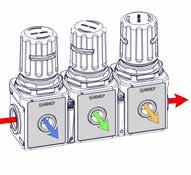
15.36 Evo FRL Series
Dimensions - FRL 1 Dimensions - FRL 2 A I M Z D B V R E C F W A B C D W E F I R M Z V 51 1175757 1/4 - 3/8 32.53147.528 M37 x 1.5 571/8 A B C D W E F I R M Z V 62 114.56768 3/8 - 1/2 3935.55933 M37 x 1.5 72.53/8 Part Number Size Thread (NPTF) Regulation Flow Rate N025 103 030 000 REG F 1 1/4 0 ÷ 8 bar (116 PSI) 2700 Nl/min N025 104 030 000 REG F 1 3/8 0 ÷ 8 bar (116 PSI) 2700 Nl/min N025 204 030 000 REG F 2 3/8 0 ÷ 8 bar (116 PSI) 3500 Nl/min N025 205 030 000 REG F 2 1/2 0 ÷ 8 bar (116 PSI) 3500 Nl/min
N025
Page 446
N030 FILT ER REGULATOR
TECHNICAL CHARACTERISTICS
15.37 Evo FRL Series
FRL 1 FRL 2 METALLIC THREAD 1/4" NPTF 3/8" NPTF 3/8" NPTF 1/2" NPTF TORQUE SPECIFICATIONS Max 15 Nm Max 20 Nm 6 bar FLOW RATE with ∆p 1 bar 2200 NI/min 3300 NI/min MOUNTING SCREWS M5 x 15 BLOW CAPACITY 28 cm3 37 cm3 FILTRATION GRADE 5 µm 20 µm STANDARD REGULATION RANGE 0 ÷ 2 bar (29 PSI) 0 ÷ 4 bar (58 PSI) 0 ÷ 8 bar STANDARD (116 PSI) 0 ÷ 12 bar (174 PSI) FLUID Compressed Air Bar MAX PRESSURE 18 bar (260 PSI) TEMPERATURE -10 °C (14 F) + 50 °C (122 F) MOUNTING POSITION Vertical
Reference standard 1907/2006 2011/65/CE PED 2014/68/UE | | 2GD Ex h TX Series Thread Regulation Range 1 1 1
03 = 1/4 NPTF 04 = 3/8 NPTF 04 = 3/8 NPTF 05 = 1/2 NPTF FRL 1 FRL 2 Size 1 = 0÷2 bar (29 PSI) 2 = 0÷4 bar (58 PSI) 3 = 0÷8 bar (116 PSI) 4 = 0÷12 bar (174 PSI) 1 = 5 µm 2 = 20 µm Filtration Grade Condesate exhaust System 1 = Vacuum-operated 2 = Automatic with float (max 8 bar)(max 116 PSI) 1 = Manometer incorporated 2 = Adapter for manometer 1/8 NPTF (Manometer not included) Manometer system Page 447
Part Numbering System
013 000 N300
N030
Condensation Drain
DEP: The vacuum-operated condensation drain is normally in the open position. It automatically drains the condensation when there is no pressure in the bowl. By pressing the hose connector, the condensation will be pressurize and will drain.
A: The automatic condensation drain with float drains the condensation when the maximum level is reached independently from the air pressure.
Regulating the Air Pressure
Follow the instructions below to set the air pressure:
1 Raise the knob to the regulating position.
2 Rotate to set the desired pressure, always in ascending order.
3 Press the knob down to lock into position. The knob can be padlocked to prevent tampering.

15.38 Evo FRL Series
Dimensions - FRL 1 Dimensions - FRL 2 A M Z D B H H R Q E C F W A B C D W E F H I M R Q Z Y 51 2335757 1/4 - 3/8 32.525.511947.5 M37 x 1.5 144 E.D .256 (6.5) 577 A B C D W E F H I M R Q Z Y 62 2706768 3/8 - 1/2 3931.5129.559 M47 x 1.5 158.5 E.D .256 (6.5) 72.59.5 Part Number Size Thread (NPTF) Filtartion Regulation Flow Rate Exhaust N030 103 231 000 FR 1 1/4 20 µm 0 ÷ 8 bar (116 PSI)2200 Nl/min DEP N030 104 231 000 FR 1 3/8 20 µm 0 ÷ 8 bar (116 PSI)2200 Nl/min DEP N030 104 232 000 FR 1 3/8 20 µm 0 ÷ 8 bar (116 PSI)2200 Nl/min A N030 204 231 000 FR 2 3/8 20 µm 0 ÷ 8 bar (116 PSI)3300 Nl/min DEP N030 205 231 000 FR 2 1/2 20 µm 0 ÷ 8 bar (116 PSI)3300 Nl/min DEP N030 205 232 000 FR 2 1/2 20 µm 0 ÷ 8 bar (116 PSI)3300 Nl/min A
DEP A DEP = Vacuum-operated A = Automatic Page 448
N040 LUBRICATOR
TECHNICAL CHARACTERISTICS
15.39 Evo FRL Series
FRL 1 FRL 2 METALLIC THREAD 1/4" NPTF 3/8" NPTF 3/8" NPTF 1/2" NPTF TORQUE SPECIFICATIONS Max 15 Nm Max 20 Nm 6 bar FLOW RATE with ∆p 1 bar 3400 NI/min 6100 NI/min MOUNTING SCREWS M5 x 15 BLOW CAPACITY 28 cm3 37 cm3 FLUID Compressed Air Bar MAX PRESSURE 18 bar (260 PSI) TEMPERATURE -10 °C (14 F) + 50 °C (122 F) MOUNTING POSITION Vertical RECOMMENDED OILS CLASS ISO 22 ISO 3448 NORMA Series Thread Part Numbering System 0 0 0
03 = 1/4 NPTF 04 = 3/8 NPTF 04 = 3/8 NPTF 05 = 1/2 NPTF FRL 1 FRL 2 Size Oil loading System 1 = Manual 2 = Automatic vacuum-operated Reference standard 1907/2006 2011/65/CE PED 2014/68/UE | | 2GD Ex h TX Page 449
013 100 N400
N040
Lubricators
The oil is added to the lubricator unit by unscrewing the cap on the top or by removing the bowl. Make sure that there is no pressure running to the unit. You can adjust the oil by using screwdriver. We recommend adding one drop of oil every 300-600 Nl/min.
Lubricators

The vacuum-operated oil loading enables the bowl to be filled with oil automatically. The system is activated by a button on top. The newly added oil, also positioned at a lower height with respect to the lubricator unit, flows into the bowl thanks to a G1/8” attachment positioned on the bottom side of the unit. Stop adding oil once the oil reaches the maximum level, shown by the windows in the side of the bowl.
15.40 Evo FRL Series
Dimensions - FRL 1 Dimensions - FRL 2 B D H I A E R W Y C F A B C D W E F H I R Y 51 178.55157 1/4 - 3/8 32.525.592.547.5117.57 A B C D W E F H I R Y 62 2006368 3/8 - 1/2 3931.5103591329.5 Part Number Size Thread (NPTF) Flow Rate Oil loading System N040 103 000 100 LUB 1 1/4 3400 Nl/min M N040 104 000 100 LUB 1 3/8 3400 Nl/min M N040 104 000 200 LUB 1 3/8 3400 Nl/min A N040 204 000 100 LUB 2 3/8 6100 Nl/min M N040 205 000 100 LUB 2 1/2 6100 Nl/min M N040 205 000 200 LUB 2 1/2 6100 Nl/min A
DEP = Manual A = Automatic vacuum-operated Push start button to prime the oil. Oil primer A A
M M Page 450
N050
TECHNICAL CHARACTERISTICS
MANUAL SHUT OFF VALVE
0 0 0 013 000 N500
15.41 Evo FRL Series
FRL 1 FRL 2 METALLIC THREAD 1/4" NPTF 3/8" NPTF 3/8" NPTF 1/2" NPTF TORQUE SPECIFICATIONS Max 15 Nm Max 20 Nm 6 bar FLOW RATE with ∆p 1 bar 2700 NI/min 3500 NI/min MOUNTING SCREWS M5 x 15 FLUID Compressed Air Bar MAX PRESSURE 18 bar (260 PSI) TEMPERATURE -10 °C (14 F) + 50 °C (122 F) MOUNTING POSITION Vertical Series Thread Part Numbering System
03 = 1/4 NPTF 04 = 3/8 NPTF 04 = 3/8 NPTF 05 = 1/2 NPTF FRL 1 FRL 2 Size Reference standard 1907/2006 2011/65/CE PED 2014/68/UE | | 2GD Ex h TX Page 451
Shut Off Valves
The shut off valve is activated in the following phases:

15.42 Evo FRL Series
Dimensions - FRL 1 Dimensions - FRL 2 A I G Z D B R E Ø8 (5/16) C F W A B C D W E F G I R Y 51 1345157 1/4 - 3/8 32.525.53247.54656 A B C D W E F G I R Y 62 1436368 3/8 - 1/2 3931.532595251 Part Number Size Thread (NPTF) Flow Rate Function Oil loading System N050 103 000 000 V3V 1 1/4 2700 Nl/min NC M N050 104 000 000 V3V 1 3/8 2700 Nl/min NC M N050 204 000 000 V3V 2 3/8 3500 Nl/min NC M N050 205 000 000 V3V 2 1/2 3500 Nl/min NC M
N050
1. By pressing the trigger switch 1, the primary circuit opens.
1 2 Page 452
2. By pressing button 2, the primary circuit closes and the secondary circuit drains. This latter position can be padlocked.
N051
TECHNICAL CHARACTERISTICS
PNEUM ATIC SHUT OFF VALVE
15.43 Evo FRL Series
FRL 1 FRL 2 METALLIC THREAD 1/4" NPTF 3/8" NPTF 3/8" NPTF 1/2" NPTF TORQUE SPECIFICATIONS Max 15 Nm Max 20 Nm 6 bar FLOW RATE with ∆p 1 bar 2700 NI/min 3500 NI/min MOUNTING SCREWS M5 x 15 FLUID Compressed Air Bar MAX PRESSURE from 2.5 bar (36 PSI) to 10 bar (145 PSI) TEMPERATURE -10 °C (14 F) + 50 °C (122 F) MOUNTING POSITION Vertical Series Thread Part Numbering System
N501 03 = 1/4 NPTF 04 = 3/8 NPTF 04 = 3/8 NPTF 05 = 1/2 NPTF FRL 1 FRL 2 Size Reference standard 1907/2006 2011/65/CE PED 2014/68/UE | | 2GD Ex h TX Page 453
0 0 0 013 000
Shut Off Valves
The pneumatic shut off valve functions in the following phases:
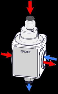
1. By pressurising the pilot "P", the primary circuit opens.
2. By removing pressure from the operator "P", the primary circuit closes and the secondary circuit drains.
15.44 Evo FRL Series
Dimensions - FRL 1 Dimensions - FRL 2 I A B D Z W E R Ø8 (5/16) C F Ø4 (5/32) A B C D W E F I R Z 51 98 51 57 1/4 - 3/8 32.525.547.5 46 19.5 A B C D W E F I R Z 62 113.563 68 3/8 - 1/2 39 31.5 59 52 22 Part Number Size Thread (NPTF) Flow Rate Function Oil loading System N051 104 000 000 V3V 1 3/8 2700 Nl/min NC P N051 205 000 000 V3V 2 1/2 3500 Nl/min NC P
N051
P = Pneumatic P Page 454
N052
TECHNICAL CHARACTERISTICS
MANUA L/ELECTRO-PNEUMATIC SHUT OFF VALVE
0 0 0 013 000 N502
15.45 Evo FRL Series
FRL 1 FRL 2 METALLIC THREAD 1/4" NPTF 3/8" NPTF 3/8" NPTF 1/2" NPTF TORQUE SPECIFICATIONS Max 15 Nm Max 20 Nm 6 bar FLOW RATE with ∆p 1 bar 2700 NI/min 3500 NI/min MOUNTING SCREWS M5 x 15 FLUID Compressed Air Bar MAX PRESSURE from 2.5 bar (36 PSI) to 10 bar (145 PSI) TEMPERATURE -10 °C (14 F) + 50 °C (122 F) MOUNTING POSITION Vertical SOLENOID See Chapter 18 - page 18.24 - 18.25 Series Thread Part Numbering System
03 = 1/4 NPTF 04 = 3/8 NPTF 04 = 3/8 NPTF 05 = 1/2 NPTF FRL 1 FRL 2 Size Reference standard 1907/2006 2011/65/CE PED 2014/68/UE | | 2GD Ex h TX Page 455
Shut Off Valves
The electro-pneumatic shut off valve functions in the following phases:

1. By activating the electric impulse, the primary circuit opens.
2. By removing the electric impulse, the primary circuit closes and the secondary circuit drains.
See Pg. 13.20 - 13.23 SOLENOIDS AND CONNECTORS
15.46 Evo FRL Series
Dimensions - FRL 1 Dimensions - FRL 2 A I Z B D C F W E R Ø8 (5/16) A B C D W E F I R Z 51 98 51 57 1/4 - 3/8 32.525.547.5 46 19.5 A B C D W E F I R Z 62 113.563 68 3/8 - 1/2 39 31.5 59 52 22 Part Number Size Thread (NPTF) Flow Rate Function Oil loading System N052 104 000 000 V3V 1 3/8 2700 Nl/min NC EP N052 205 000 000 V3V 2 1/2 3500 Nl/min NC EP
N052
*NB: Standard without solenoid EP = Electro-pneumatic NB: ATEX II 2GD Ex h TX category can be reclassified in accordance to the kind of solenoid applied.
Page 456
N060
TECHNICAL CHARACTERISTICS
SOFT START VALVE
0 0 0 013 000 N600
15.47 Evo FRL Series
FRL 1 FRL 2 METALLIC THREAD 1/4" NPTF 3/8" NPTF 3/8" NPTF 1/2" NPTF TORQUE SPECIFICATIONS Max 15 Nm Max 20 Nm 6 bar FLOW RATE with ∆p 1 bar 2700 NI/min 3500 NI/min MOUNTING SCREWS M5 x 15 Bar MAXIMUM INLET PRESSURE 10 bar (145 PSI) FLUID Compressed Air TEMPERATURE -10 °C (14 F) + 50 °C (122 F) ASSEMBLY POSITION Vertical MOUNTING POSITION End of all FRL components Series Thread Part Numbering System
03 = 1/4 NPTF 04 = 3/8 NPTF 04 = 3/8 NPTF 05 = 1/2 NPTF FRL 1 FRL 2 Size Reference standard 1907/2006 2011/65/CE PED 2014/68/UE | | 2GD Ex h TX Page 457
Soft Start Valve
Our soft start valve is a pneumatic device that allows a pneumatic circuit to be pressurised gradually. With the adjustment screw shown in the drawing to the right, you can progressively increase or decrease the air flow introduced to your pneumatic circuit. This valve is designed to completely open the air flow of your circuit at 50% of the inlet pressure.
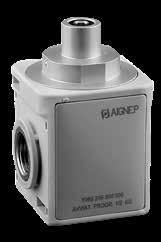
15.48 Evo FRL Series
Dimensions - FRL 1 Dimensions - FRL 2 A I CH Z D B E R C F W A B C D W E F I R Z CH 51 84.55157 1/4 - 3/8 32.525.547.52823.55 A B C D W E F I R Z CH 62 97.56368 3/8 - 1/2 3931.5593325 5 Part Number Size Thread (NPTF) Flow Rate N060 103 000 000 APE 1 1/4 2700 Nl/min N060 104 000 000 APE 1 3/8 2700 Nl/min N060 204 000 000 APE 2 3/8 3500 Nl/min N060 205 000 000 APE 2 1/2 3500 Nl/min
N060
1 Page 458
N090 AIR D ISTRIBUTOR
TECHNICAL CHARACTERISTICS
15.49 Evo FRL Series
FRL 1 FRL 2 METALLIC THREAD 1/4" NPTF 3/8" NPTF 3/8" NPTF 1/2" NPTF TORQUE SPECIFICATIONS Max 15 Nm Max 20 Nm 6 bar FLOW RATE with ∆p 1 bar 3400 NI/min 6100 NI/min MOUNTING SCREWS M5 x 15 FLUID Compressed Air Bar MAX PRESSURE 18 bar (260 PSI) TEMPERATURE -10 °C (14 F) + 50 °C (122 F) MOUNTING POSITION Vertical Series Thread W
Numbering System
03 = 1/4 NPTF 04 = 3/8 NPTF 04 = 3/8 NPTF 05 = 1/2 NPTF FRL 1 FRL 2 Size Thread Y 02 02 = 1/8 NPTF 03 = 1/4 NPTF 04 = 3/8 NPTF 03 = 1/4 NPTF 04 = 3/8 NPTF 05 = 1/2 NPTF Reference standard 1907/2006 2011/65/CE PED 2014/68/UE | | 2GD Ex h TX Page 459
Part
013 000 N900
N090
The air distributor allows you to branch off your air flow to several components such as pressure switches and other units. The air distributor can be placed anywhere in your air treatment unit.
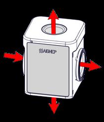
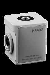
15.50 Evo FRL Series
Dimensions - FRL 1 Dimensions - FRL 2 A I D C F Y Y W W A C D W F I Y 51 51 57 1/4 - 3/8 25.5 47.5 1/4 - 3/8 A C D W F I Y 62 63 68 3/8 - 1/2 31.5 59 1/4 - 3/8 - 1/2 Part Number Size Thread (NPTF) Flow Rate N090 103 030 000 DIS 1 1/4 - 1/4 3400 Nl/min N090 104 030 000 DIS 1 3/8 - 1/4 3400 Nl/min N090 104 040 000 DIS 1 3/8 - 3/8 3400 Nl/min N090 204 030 000 DIS 2 3/8 - 1/4 6100 Nl/min N090 204 040 000 DIS 2 3/8 - 3/8 6100 Nl/min N090 205 030 000 DIS 2 1/2 - 1/4 6100 Nl/min N090 205 050 000 DIS 2 1/2 -1/2 6100 Nl/min
Distributor
Air
Page 460
TECHNICAL CHARACTERISTICS
Part Numbering System
15.51 Evo FRL Series
L
N100 FR +
FRL 1 FRL 2 METALLIC THREAD 1/4" NPTF 3/8" NPTF 3/8" NPTF 1/2" NPTF TORQUE SPECIFICATIONS Max 15 Nm Max 20 Nm 6 bar FLOW RATE with ∆p 1 bar 1500 NI/min 2700 NI/min MOUNTING SCREWS M5 x 15 BLOW CAPACITY 28 cm3 37 cm3 FILTRATION GRADE 5 µm 20 µm STANDARD REGULATION RANGE 0 ÷ 2 bar (29 PSI) 0 ÷ 4 bar (58 PSI) 0 ÷ 8 bar STANDARD (116 PSI) 0 ÷ 12 bar (174 PSI) FLUID Compressed Air Bar MAX PRESSURE 18 bar (260 PSI) TEMPERATURE -10 °C (14 F) + 50 °C (122 F) MOUNTING POSITION Vertical
Reference standard 1907/2006 2011/65/CE PED 2014/68/UE | | 2GD Ex h TX Series Thread Regulation Range 1 1 1 013 100 N010 03 = 1/4 NPTF 04 = 3/8 NPTF 04 = 3/8 NPTF 05 = 1/2 NPTF FRL 1 FRL 2 Size 1 = 0÷2 bar (29 PSI) 2 = 0÷4 bar (58 PSI) 3 = 0÷8 bar (116 PSI) 4 = 0÷12 bar (174 PSI) 1 = 5 µm 2 = 20 µm Filtration Grade Condesate exhaust System 1 = Vacuum-operated 2 = Automatic with float (max 8 bar) (max 116 bar) Oil loading System 1 = Manual 2 = Automatic vacuum-operated 1 = Manometer incorporated 2 = Adapter for manometer 1/8 NPTF (Manometer not included) Manometer system Page 461
Condensation Drain
DEP: The vacuum-operated condensation drain is normally in the open position. It automatically drains the condensation when there is no pressure in the bowl. By pressing the hose connector, the condensation will be pressurize and will drain.
A: The automatic condensation drain with float drains the condensation when the maximum level is reached independently from the air pressure.
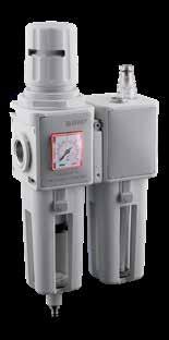
Regulating the Air Pressure
Follow the instructions below to set the air pressure:
1 Raise the knob to the regulating position.
2 Rotate to set the desired pressure, always in ascending order.
3 Press the knob down to lock into position. The knob can be padlocked to prevent tampering.
15.52 Evo FRL Series
Dimensions - FRL 1 Dimensions - FRL 2 A J Z D H B L K1 K2 P C F W E R Y Q ABCDEFHIJ K1 K2 LPQRWYZ 102 233575732.525.511947.598.54535.55.534.5 E.D .256 (6.5) 1441/4-3/8757 ABCDEFHIJ K1 K2 LPQRWYZ 124 27067683931.5129.5591215341.55.540 E.D .256 (6.5) 158.53/8-1/29.572.5 Part Number Size Thread (NPTF) Filtartion Regulation Flow Rate Exhaust N100 103 231 100 FR+L1 1/4 20 µm 0 ÷ 8 bar (116 PSI)1500 Nl/min DEP N100 104 231 100 FR+L1 3/8 20 µm 0 ÷ 8 bar (116 PSI)1500 Nl/min DEP N100 104 232 100 FR+L1 3/8 20 µm 0 ÷ 8 bar (116 PSI)1500 Nl/min A N100 204 231 100 FR+L2 3/8 20 µm 0 ÷ 8 bar (116 PSI)2700 Nl/min DEP N100 205 231 100 FR+L2 1/2 20 µm 0 ÷ 8 bar (116 PSI)2700 Nl/min DEP N100 205 232 100 FR+L2 1/2 20 µm 0 ÷ 8 bar (116 PSI)2700 Nl/min A
N100
DEP A DEP
Vacuum-operated A = Automatic Page 462
=
N400
TECHNICAL CHARACTERISTICS
4 0 1 013 000 N040
15.53 Evo FRL Series
FIL + F C
FRL 1 FRL 2 METALLIC THREAD 1/4" NPTF 3/8" NPTF 3/8" NPTF 1/2" NPTF TORQUE SPECIFICATIONS Max 15 Nm Max 20 Nm 6 bar FLOW RATE with ∆p 1 bar 1800 NI/min 3500 NI/min MOUNTING SCREWS M5 x 15 BLOW CAPACITY 28 cm3 37 cm3 FILTRATION GRADE 5 µm + 0.01 µm FLUID Compressed Air Bar MAX PRESSURE 18 bar (260 PSI) TEMPERATURE -10 °C (14 F) + 50 °C (122 F) CONDENSATION EXHAUST Vacuum-operated MOUNTING POSITION Vertical Series Thread Part Numbering System
03 = 1/4 NPTF 04 = 3/8 NPTF 04 = 3/8 NPTF 05 = 1/2 NPTF FRL 1 FRL 2 Size 1 = 0.01 µm Filtration Grade Condesate exhaust System Reference standard 1907/2006 2011/65/CE PED 2014/68/UE | | 2GD Ex h TX 1 = Vacuum-operated 2 = Automatic with float (max 8 bar) (116 PSI) Page 463
Condensation Drain
DEP: The vacuum-operated condensation drain is normally in the open position. It automatically drains the condensation when there is no pressure in the bowl. By pressing the hose connector, the condensation will be pressurize and will drain.
A: The automatic condensation drain with float drains the condensation when the maximum level is reached independently from the air pressure.
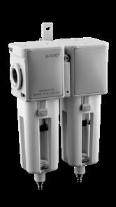
Coalescer Cartridge
The coalescer cartridge is made of a microfiber layer with an external stainless steel structure. The coalescer cartridge uses inertial impact, interception and coalescense to form liquid particles into drops. These drops will fall into the bottom of the bowl. The coalescer filter is used as an oil separator which removes oil-vapours from the air output. We recommend installing a 5 μm filter upstream to protect the coalescing filter from choking the cartridge.
COALESCER CARTRIDGE
15.54 Evo FRL Series
Dimensions - FRL 1 Dimensions - FRL 2 A J I L D B H Q K1 K2 P C F W E R Y ABCDEFHIJ K1 K2 LPQRWYZ 102 176575732.525.511947.598.54535.55.534.5 E.D .256 (6.5) 1441/4-3/8757 ABCDEFHIJ K1 K2 LPQRWYZ 124 197.567683931.5129.5591215341.55.540 E.D .256 (6.5) 158.53/8-1/29.572.5 Part Number Size Thread (NPTF) Filtartion Flow Rate N400 103 401 000 FIL+FC 1 1/4 5 µm + 0.01 µm 1800 Nl/min N400 104 401 000 FIL+FC 1 3/8 5 µm + 0.01 µm 1800 Nl/min N400 204 401 000 FIL+FC 2 3/8 5 µm + 0.01 µm 3500 Nl/min N400 205 401 000 FIL+FC 2 1/2 5 µm + 0.01 µm 3500 Nl/min
N400
INTERLACED MICROFIBERS
DEP A Page 464
REG16
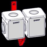
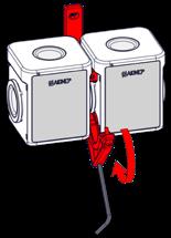
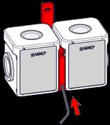
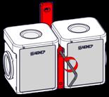
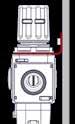
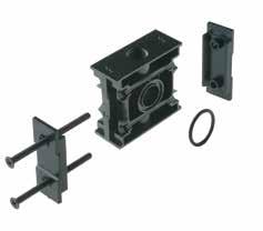
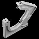
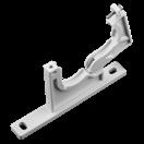

15.55 Evo FRL Series
CLAMP BRACKET
Part Number REG16 1Y 50 00 ZI FRL 1 REG16 2Y 50 00 ZI FRL 2 Part Number Y501 100 000 000 FRL 1 Y501 200 000 000 FRL 2 Part Number Y502 100 000 000 FRL 1 Y502 200 000 000 FRL 2 Part Number T545 10Y 000 000 FRL 1 T545 20Y 000 000 FRL 2 1 2 3 4 Page 465
T545 COALESCER FILTER
FIL04


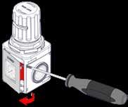

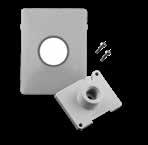

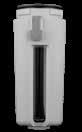
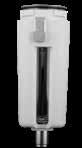
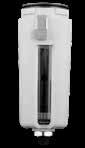
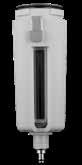
15.56 Evo FRL Series
FOR FILTER UNIT
FOR LUBRICATOR UNIT
MANOMETER
MANOMETER ADAPTER NPTF 1/8 NPTF Part Number FIL04 1Y3 805 SC FRL 1 5 μm FIL04 1Y3 820 SC FRL 2 5 μm FIL04 2Y3 805 SC FRL 1 20 μm FIL04 2Y3 820 SC FRL 2 20 μm Part Number Y520 100 001 000 FRL 1 DEP Y520 100 002 000 FRL 1 A Y520 200 001 000 FRL 2 DEP Y520 200 002 000 FRL 2 A *DEP: Vacuum-operated *A: Automatic with float A DEP Part Number Y530 100 000 100 FRL 1 MAN Y530 100 000 200 FRL 1 A Y530 200 000 100 FRL 2 MAN Y530 200 000 200 FRL 2 A *MAN: Manual oil loading system*A: Automatic oil loading system A MAN Part Number Bar MAS1 1N0 020 000 FRL 1 0 - 4 MAS1 1N0 040 000 FRL 1 0 - 12 MAS1 2N0 020 000 FRL 2 0 - 4 MAS1 2N0 040 000 FRL 2 0 - 12 Part Number NPTF MAS0 112 000 000 FRL 1 1/8 MAS0 212 000 000 FRL 2 1/8 NPTF Page 466
SINTERED FILTER Y520 BOWL
Y530 BOWL
MAS1
MAS0

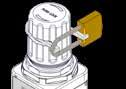
15.57 Evo FRL Series MANOMETERS Media • Compressed Air Inert gases Steam Non-highly viscose and non-crystallizing liquids MAN09 MANOMETER BACK CONNECTION Code bar DB1B2SW G (NPTF) MAN09 N2 040 000 0 ÷ 12 40 2541.5121/8 min max Temperature -20 °C+60 °C B1 SW D B2 NPTF EN 837-1 Reference Standard IP31 EN 60 529
PADLOCK FOR ADJUSTER AND ADJUSTER FILTER KIT Part Number Y503 100 000 000 FRL 1 Y503 200 000 000 FRL 2 Page 467
Y503
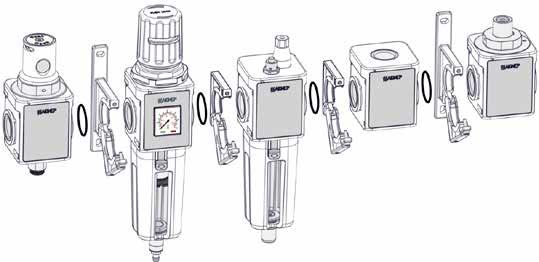


15.58 Evo FRL Series
Part Numbers 1° POS + 2° POS + 3° POS + 4° POS + 5° POS + 6° POS + 7° POS + 8° POS + 9° POS + 10° POS Enter your part number and accessory part number in the table below to configure your FRL Evo system Y501 Y502 Page 468
SET YOUR FRL EVO
15.59 Evo FRL Series Page 469
15.60 Evo FRL Series Page 470
15.61 Evo FRL Series Page 471
