UNMISTAKABLE STYLE HIGHLIGHTED BY SLEEK AND PURPOSEFUL DOWN EAST LINES. WHETHER YOU ARE FISHING FOR MARLIN, PLANNING AN EPIC EXPEDITION, OR STOPPING INTO THE YACHT CLUB FOR DINNER, YOU WILL BE PROUD TO BE THE OWNER.
Boat Engine(s)
1. Table of Contents
2. Startup Proceedure
3. Commissioning Checklist
4. General Specification Introduction
5. Electrical
6. Fishbox System
7. Fuel System
8. Head Operation
9. Hot & Cold Water System
10. Livewell Operation
11. Saltwater Washdown
12. Seacock Location
13. Care & Maintenance
14. Warranty
15. Recommended Tools
16. Safety
17. Construction Detail
18. YachtSense Operation
19. Vessel Operation
20. Fuse & Breaker Locations
21. Accident report
22. Air Condition
23. Generator Startup Proceedure
24. Fishing Knots
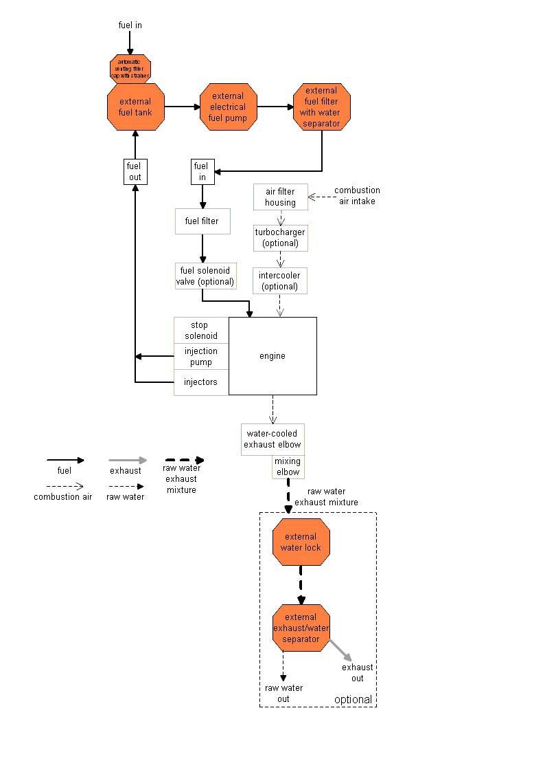
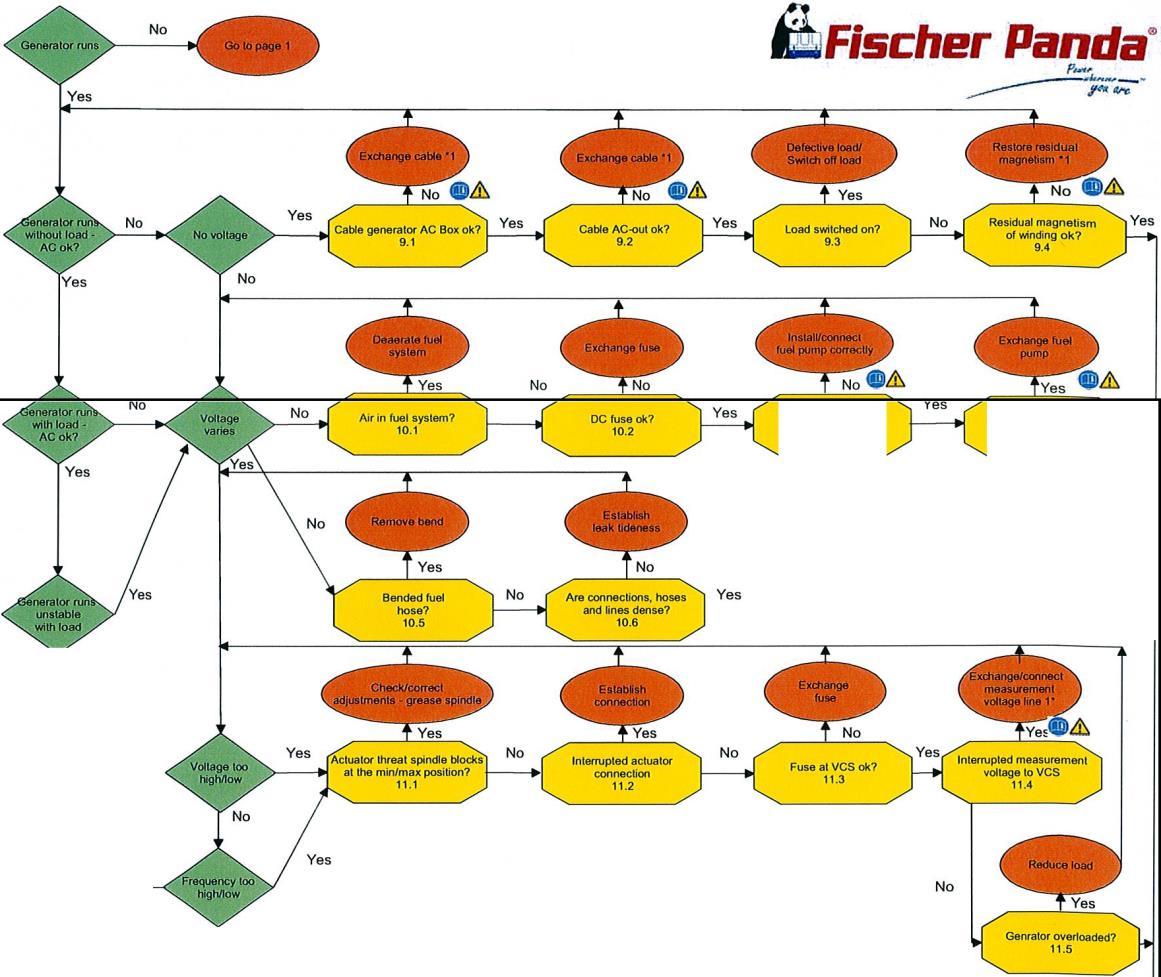
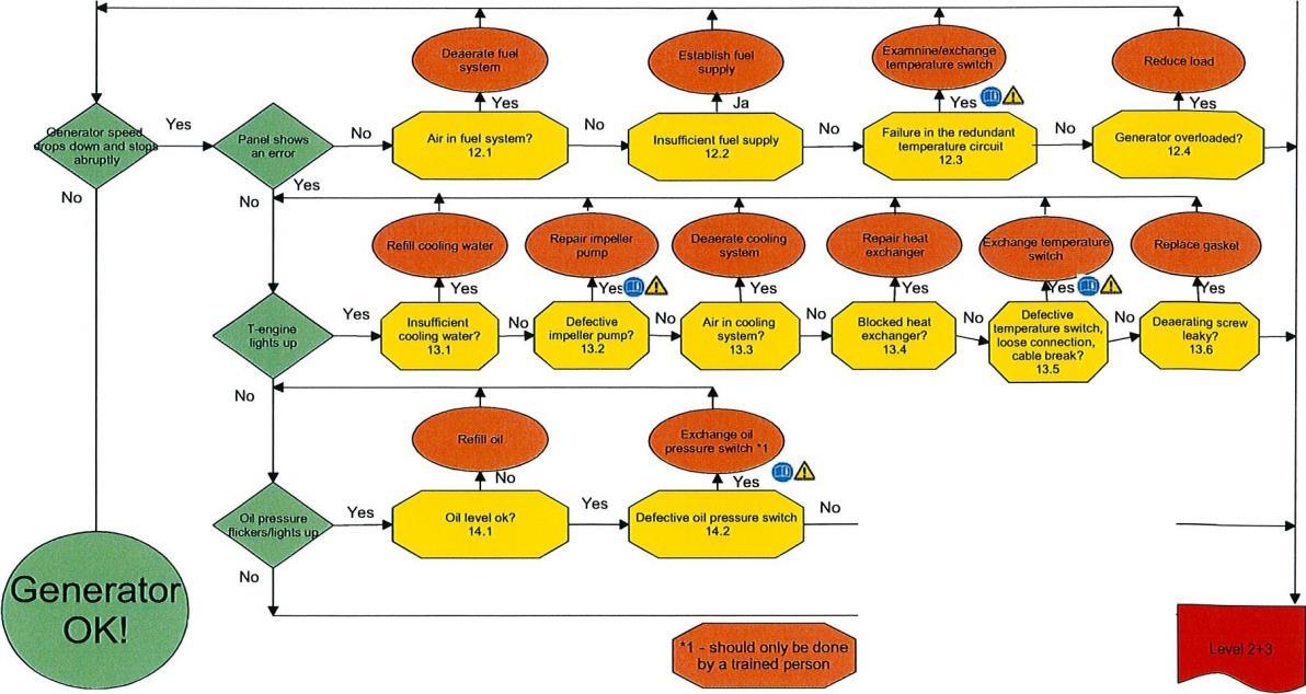
25. Fischer Panda General Faults & Maintenance
26. Panda Generator Troubleshooting guide
27. AC (Alternating Current) Operation
28. Troubleshooting
Chapter 0
Chapter 1
Chapter 2
Chapter 3
Chapter 4
Chapter 5
Chapter 6
Chapter 7
Chapter 8
Chapter 9
Chapter 10
Chapter 11
Chapter 12
Chapter 13
Chapter 14
Chapter 15
Chapter 16
Chapter 17
Chapter 18
Chapter 19
Chapter 20
Chapter 21
Chapter 22
Chapter 23
Chapter 24
Chapter 25
Chapter 26
Chapter 27
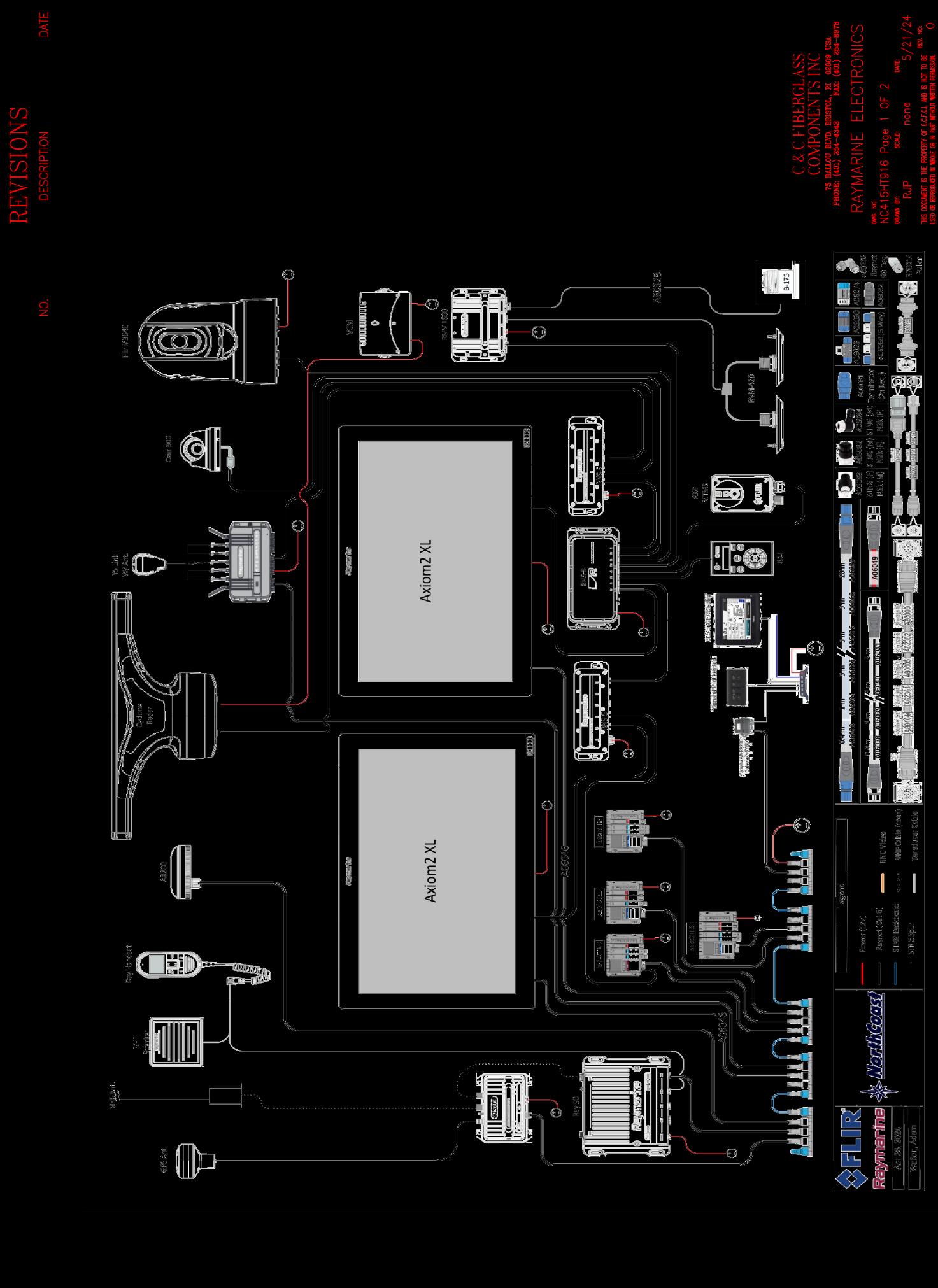
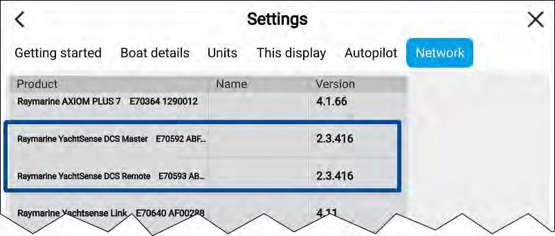
Raymarine Support (YachtSense) - 1 800 539 5539 –
https://www.raymarine.com/en-us/support
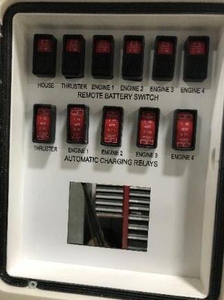
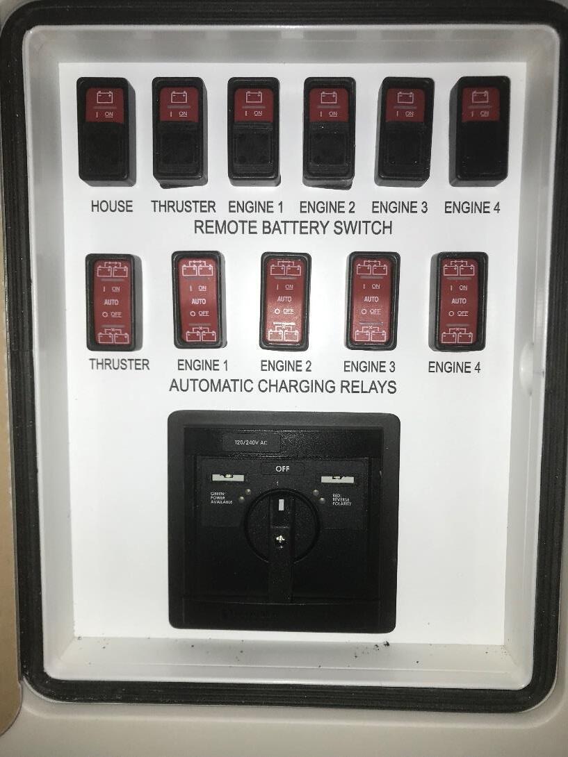
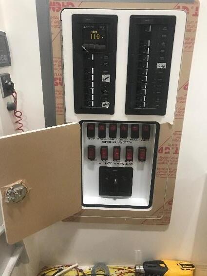
• Located at the helm you will find the NorthCoast 415 Battery Startup Switches See pic 1
•
• The Remote Battery Switches consist of House, Thruster, Engine 1 /Generator, Engine 2, Engine 3, Engine 4 in this order.
•
• Before turning anything on check that the Automatic Charging Relays Should be set to on or Auto and left that way. Now you can start to turn on Battery switch proceedure.
1. Power up the HOUSE and wait approximately 30 second for the system to boot up.
2. Once booted up the MFD at the dash will be fully functional. SEE pic-2
3. Once Yacht Sense if fully functional now you are able to start any device on board.
4. Engine Remote Battery Switches 1 thru 4 and Thruster: can now be turned on.
DURING THIS PROCESS DO NOT TURN ON ANY OTHER DEVICE
• Pic-2 - Functional MFD
Preliminary
COMMISSIONING CHECKLIST
• Check hull carefully for damage in transit
• Check propeller, nuts, cotter pin, and zincs
• Check loose gear on boat
Pre-Launch
• Read Owner's Handbook and OEM manuals
• Cover cushions or remove them from boat in order to protect them during commissioning
• Install transducers
• Check battery charge with battery test switch on the electrical panel
• Close seacocks
• Check all hose clamps & tighten as required
• Check engine oil, transmission & coolant level
• Install portlight screens
• Locate: Ignition keys, Bilge Pump
• Touch up bottom paint
• Acquire: Dock Lines, Fenders
• Stow remaining loose gear
Launch
• Reinstall garboard drain
• Check for leaks
• Check operation of seacocks
• De-winterize engine and head
• Check expiry dates on flare kits, fire extinguishers and other like equipment
Systems Check
1. Fill water tanks--flush tank twice to eliminate non-toxic antifreeze
2. Check water pressure system
3. Fill fuel tanks
Engine Start
Ignition
Start engine
Run engine under load
Check operation of all pumps electrical & manual
Check operation of head no leaks
Check optional Y valve for correct discharge
Check all AC/DC options for correct operation
Acquire and secure ground tackle
Read engine owner's manual
Check alignment and hook up couplings
Check oil pressure, water temperature, charging gauges Check engine manual for proper operation
Check fuel filter for bubbles--Check fuel lines for leaks
Check transmission for operation Trial Run
1. Monitor engine performance
2. Check bilge for leaks
3. Check and/or calibrate all instruments as needed
Clean Up
1. Clean bilge
2. Vacuum boat throughout
3. Wash down deck & hull
Work Performed by: Checked by: Date:
Return a signed copy of this commissioning checklist to NorthCoast Customer Service Department.
ELECTRICAL
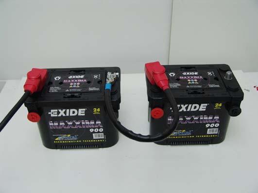
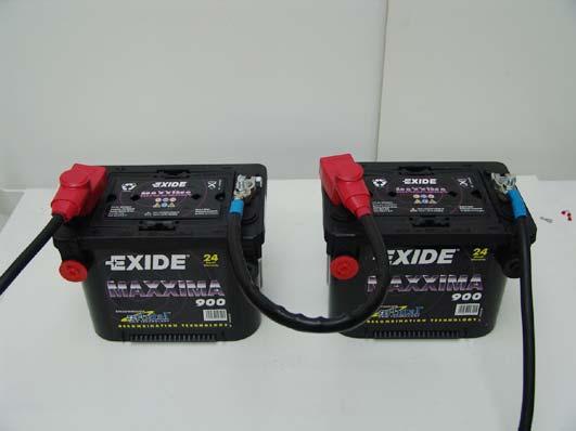
Electrical System DC Batteries
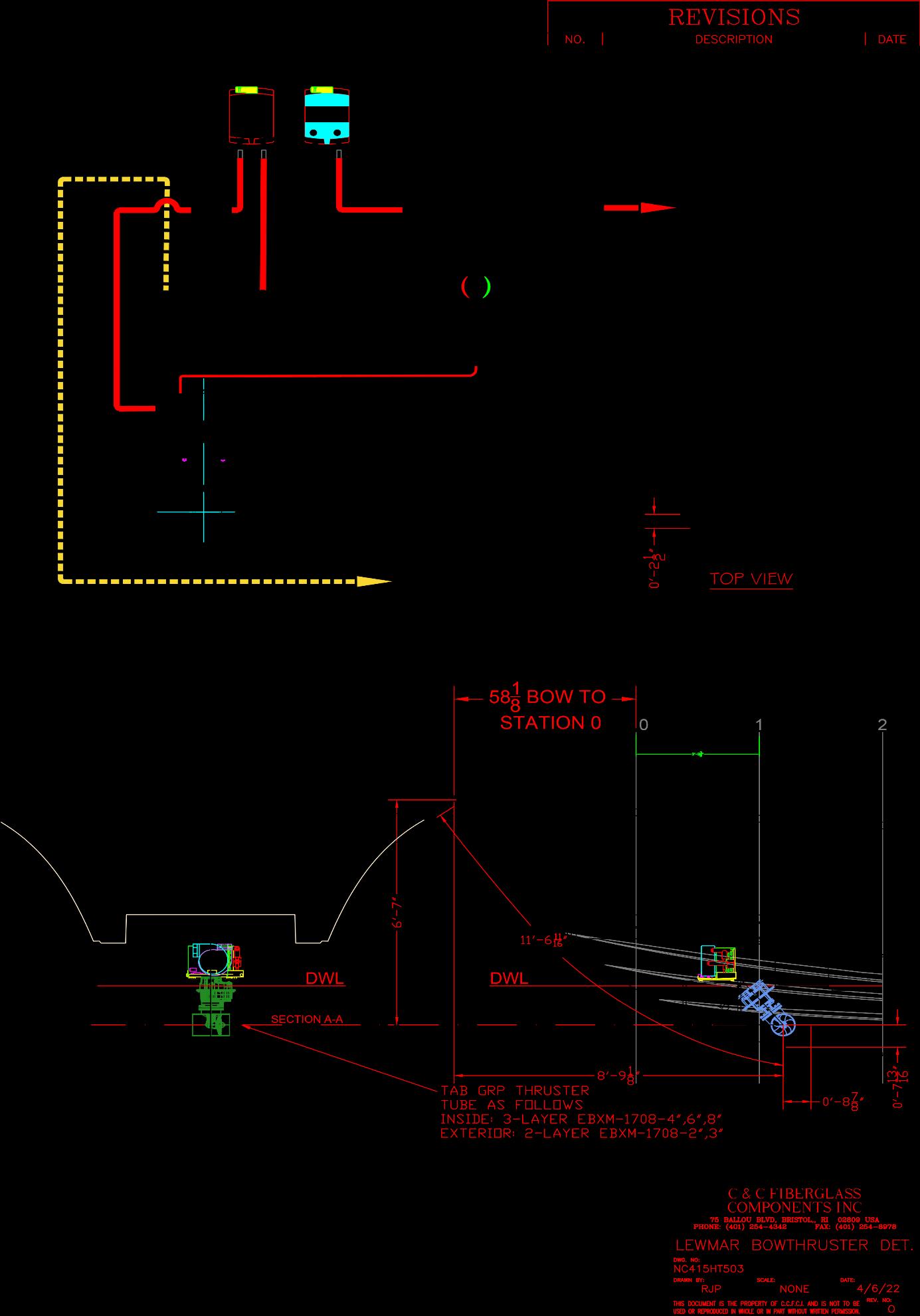
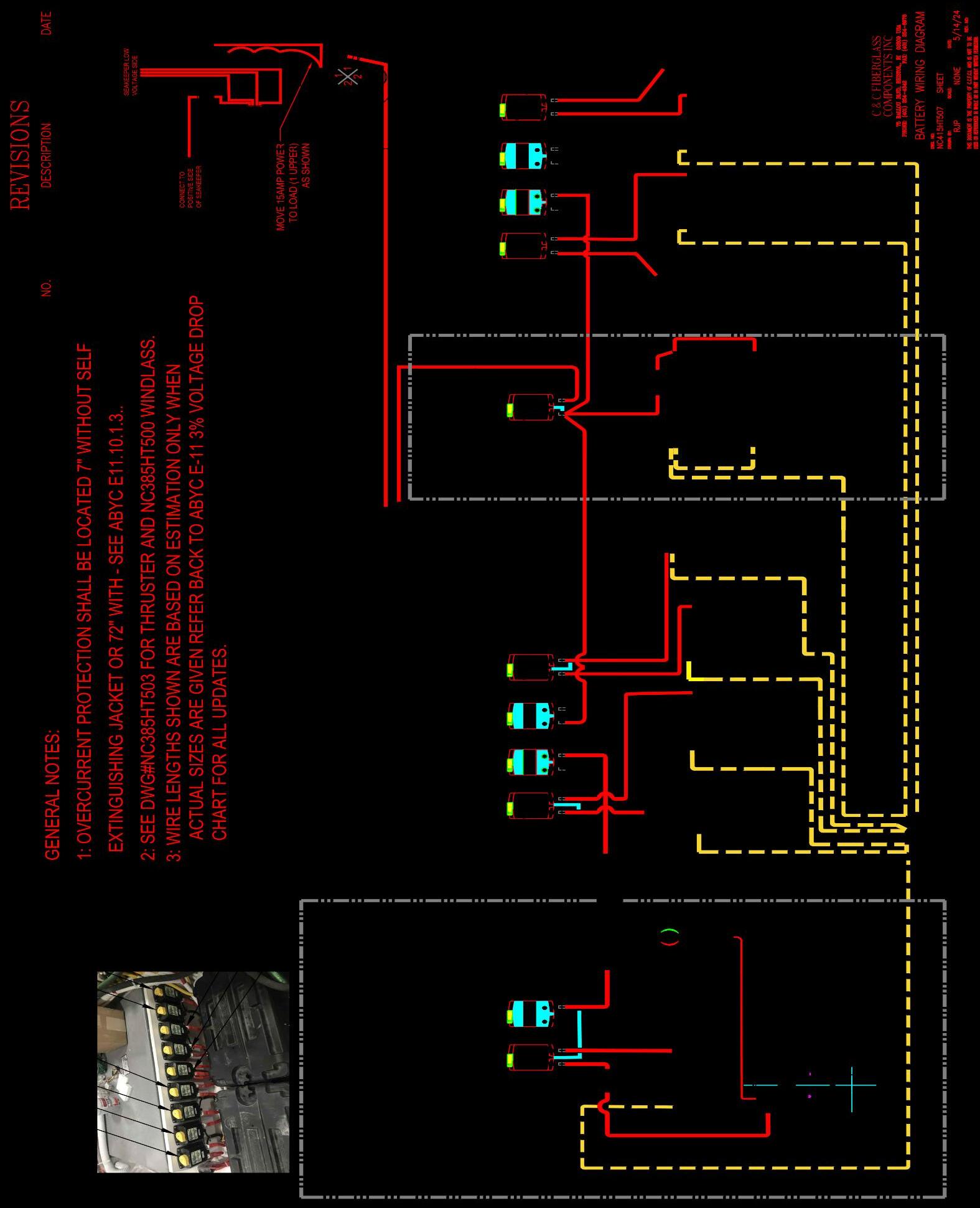
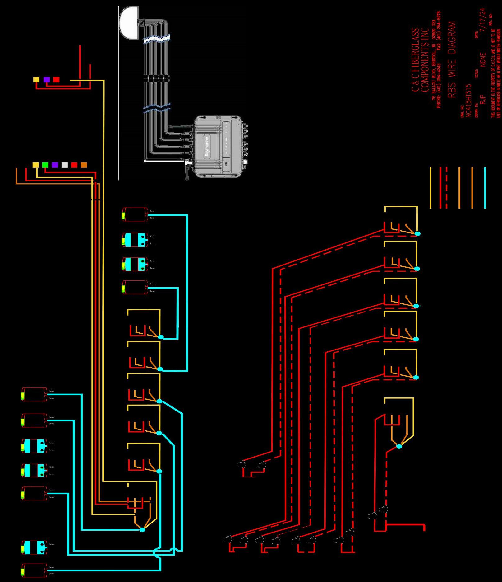
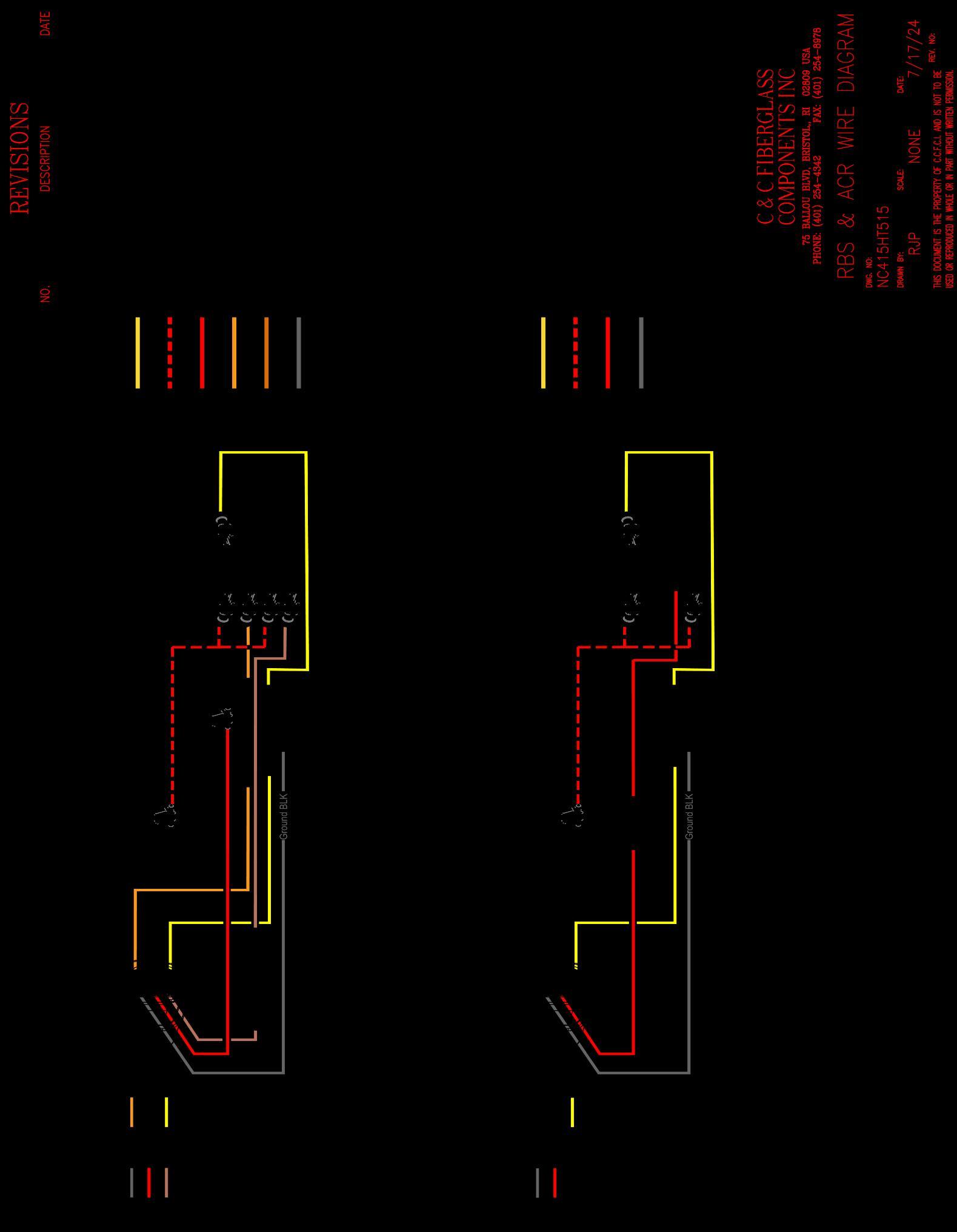
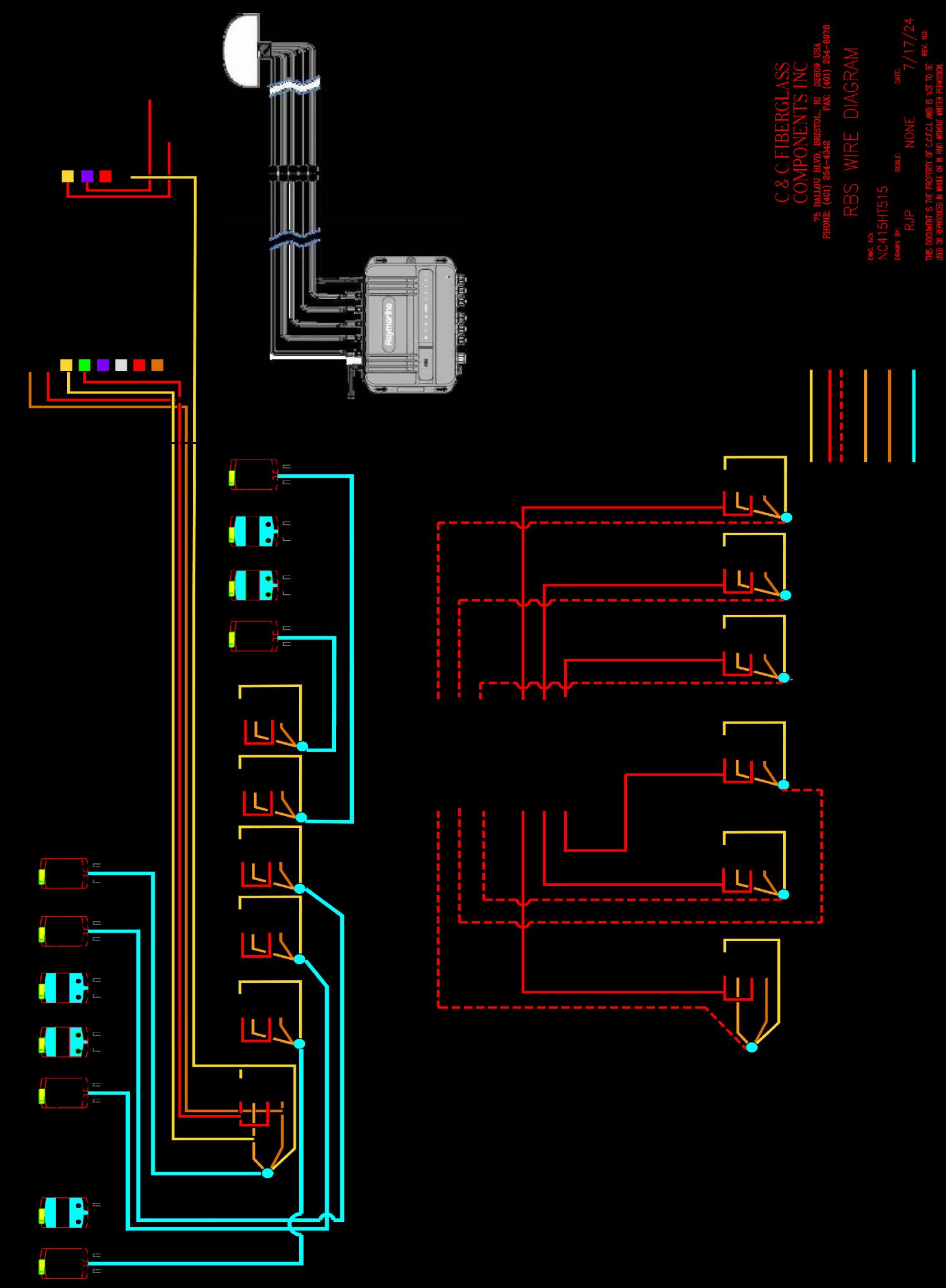
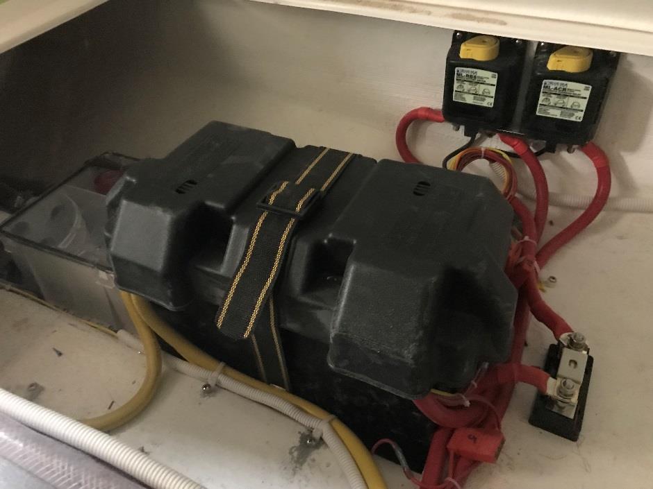
A direct current electrical system is provided. The system is comprised of one Group 31 starting battery per engine, rated at 1155mca,100amh,200rc. This is located in the battery box under Cockpit Floor. The house battery consists of two 4d batteries wired in parallel all located on the port side under the cockpit floor. There is a bow thruster battery located under the aft queen bunk this is also a group 31 battery. The boats batteries are all controlled remotely via switch panel located at the helm station reference drawing # NC415HT515. Labels and functions are as shown
Yachtsense
BONDING AND LIGHTNING PROTECTION
• LIGHTNING PROTECTION
The following, adapted from the ABYC safety standards, are suggestions only and in no way guarantee safety.
1) If possible, remain inside the boat and close all hatches during a lightning storm. Do not contact any metallic objects or components of the electrical system inside the vessel.
2) Avoid making contact with any items connected to the bonding system (engines, generator, thru-hulls, etc.) and especially in a way to bridge between two of them.
3) No one should be in the water during a lightning storm.
4) If the boat has been struck by lightning, the compass and all electrical gear should be checked to determine that no damage or change in calibration has occurred.
ELECTRICAL SYSTEMS
12 VOLT DC SYSTEM
• The NorthCoast 415HT is supplied with the YachtSense Feature YachtSense™ is an advanced digital control system affording complete command and control of a vessel's electrical systems. Its innovative modular design and industry-leading safety features make YachtSense digital control the future of modern vessel automation.
• YachtSense Digital Control
• A modular system that can be expanded with modules like high and low power switching modules, reverse modules, and signal modules.
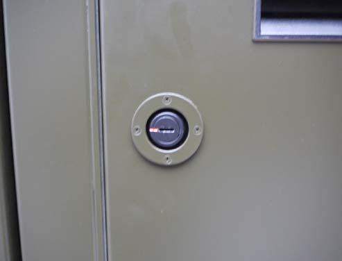
• BATTERY SWITCH
The battery switches consist of Remote Battery Switch located in the machinery room which are controlled with Contura Control switch they can be set to auto-off-on and are located at the helm station.
The Manual Control Override Knob provides (Remote Battery Switch Only): • an added level of safety that allows manual ON-OFF control with or without power • LOCK OFF for servicing the electrical system A remote LED (sold separately) indicates a closed connection between battery bank and load, or between two battery banks when used as an emergency cross-connect.
Remote Operation. The momentary (SPDT) (ON)-OFF-(ON)
Remote Control Contura Switch can provide cross connect and/or battery isolation. The Control Switch should be mounted in a convenient location.
• To connect battery bank to load, or combine battery banks
• Momentarily depress control switch actuator to “ON”. Remote LED indicates closed connection. *
• To disconnect battery bank from load, or isolate battery banks that are connected
• Momentarily depress control switch actuator to “OFF”. *
• To connect battery bank to load, or combine battery banks
• With Override Knob in (REMOTE position), push button until latched (Push to Latch On
ELECTRICAL
• To disconnect battery bank from load, or isolate battery banks that are connected
• Rotate Override Knob to right to release button from Latch On mode (button pops up). Rotate Override Knob to left (REMOTE position).
• To prevent remote operation
• Rotate Override Knob to right (LOCK OFF position)
• To secure for servicing
• With Override Knob in (LOCK OFF position), pass cable tie through hole
• If the Control Switch is held ON or OFF for 5 seconds, the internal coil protection will engage and the Remote Battery Switch/Solenoid Switch will not respond to further remote input for approximately 10 seconds.
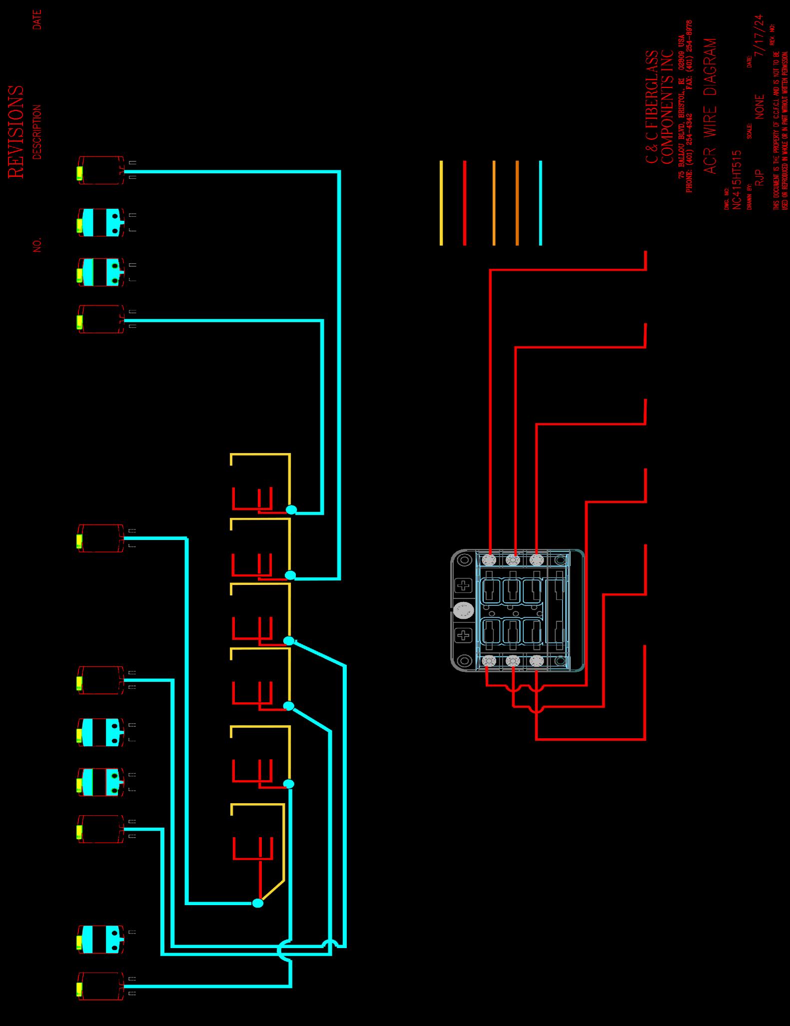
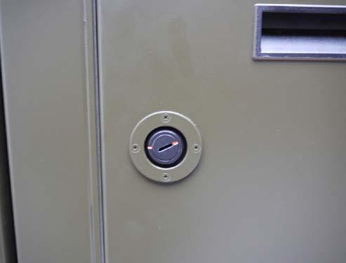
The Automatics Charging relays “ACR” is located in the machinery room which are controlled with the carling switches that are located at the helm they can be set to On-Auto-Off
Manual Control Override Knob PN 7622 / PN 7623
The Manual Control Override Knob provides: •an added level of safety that allows manual ON-OFF control with or without power
•LOCK OFF for servicing the electrical system
Remote LEDs in control switch indicate when ML-Series ACR is in manual override condition.
Manual Control Override Knob Operations*
To combine battery banks With Override Knob in REMOTE position, push button until latched (Push to Latch On).
To isolate battery banks that are connected Rotate Override Knob to right to release button from Latch On mode (button pops up). Rotate Override Knob to left (REMOTE position).
To prevent remote operation
Rotate Override Knob to right (LOCK OFF position).
To secure for servicing
With Override Knob in LOCK OFF position, pass cable tie through hole.
ELECTRICAL
1 2 * Operating the Manual Control Override Knob will override automatic operation of the ML-Series ACR for 10 minutes if the override forces a change in switch state.
† The ML-Series ACR will wait 10 minutes if it attempts to automatically close while the manual knob is rotated to LOCK OFF.
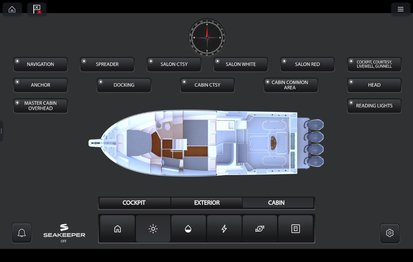
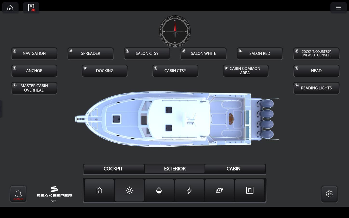
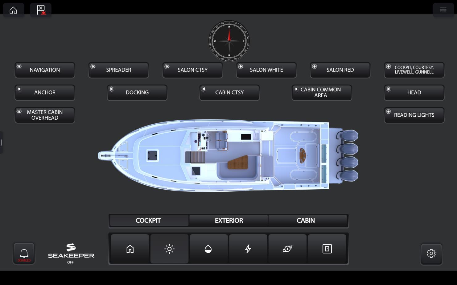
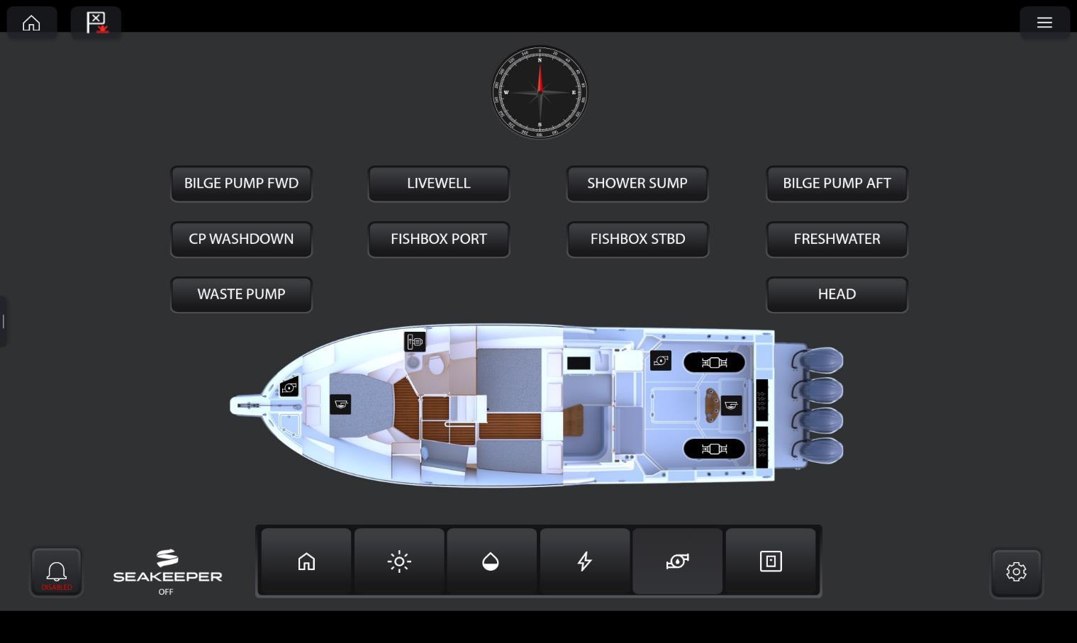
See below for MFD screen switch navigation
YACHTSENSE INTERIOR
YACHTSENSE EXTERIOR
YACHTSENSE MAIN DECK
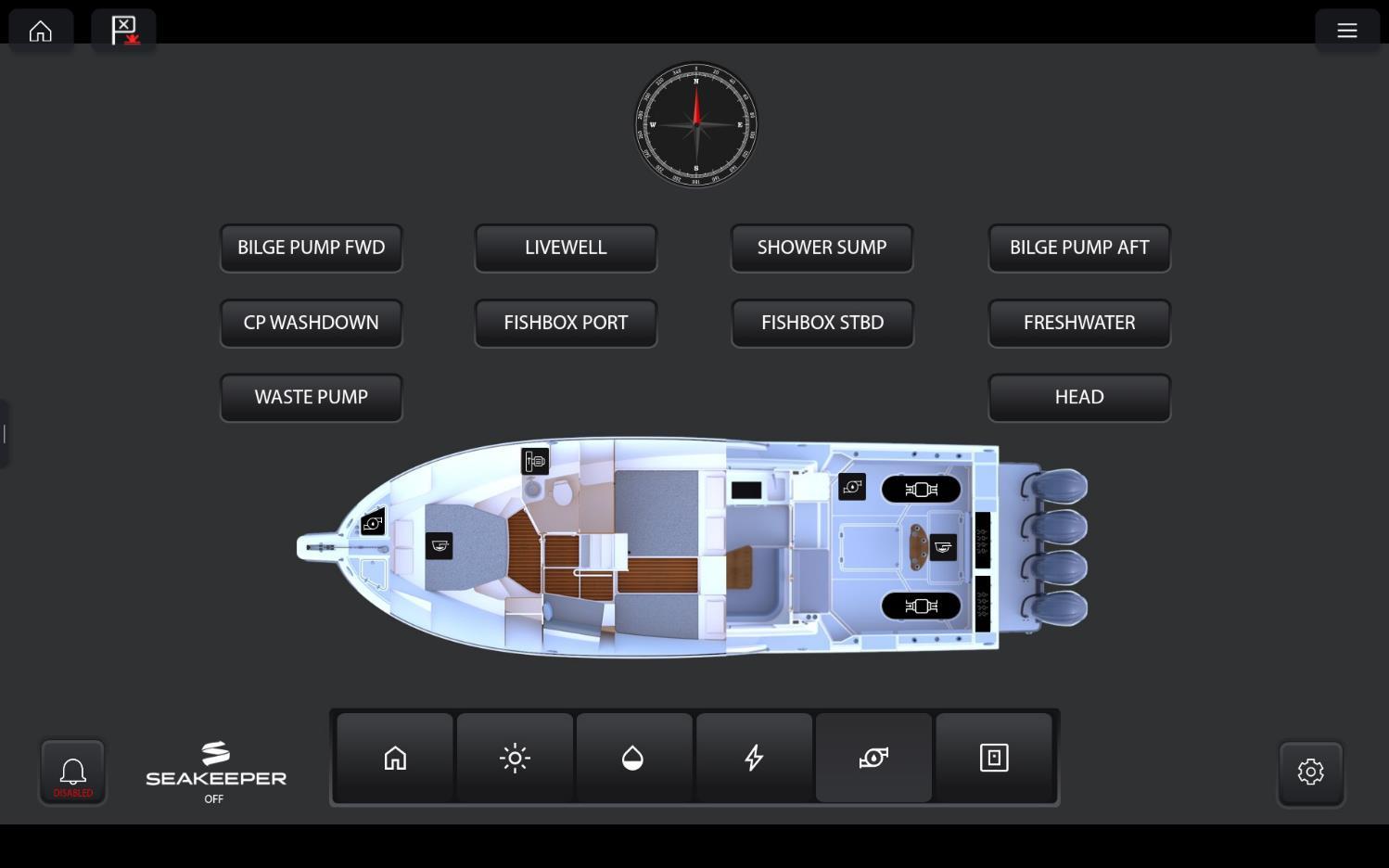
▪ BILGE PUMPS
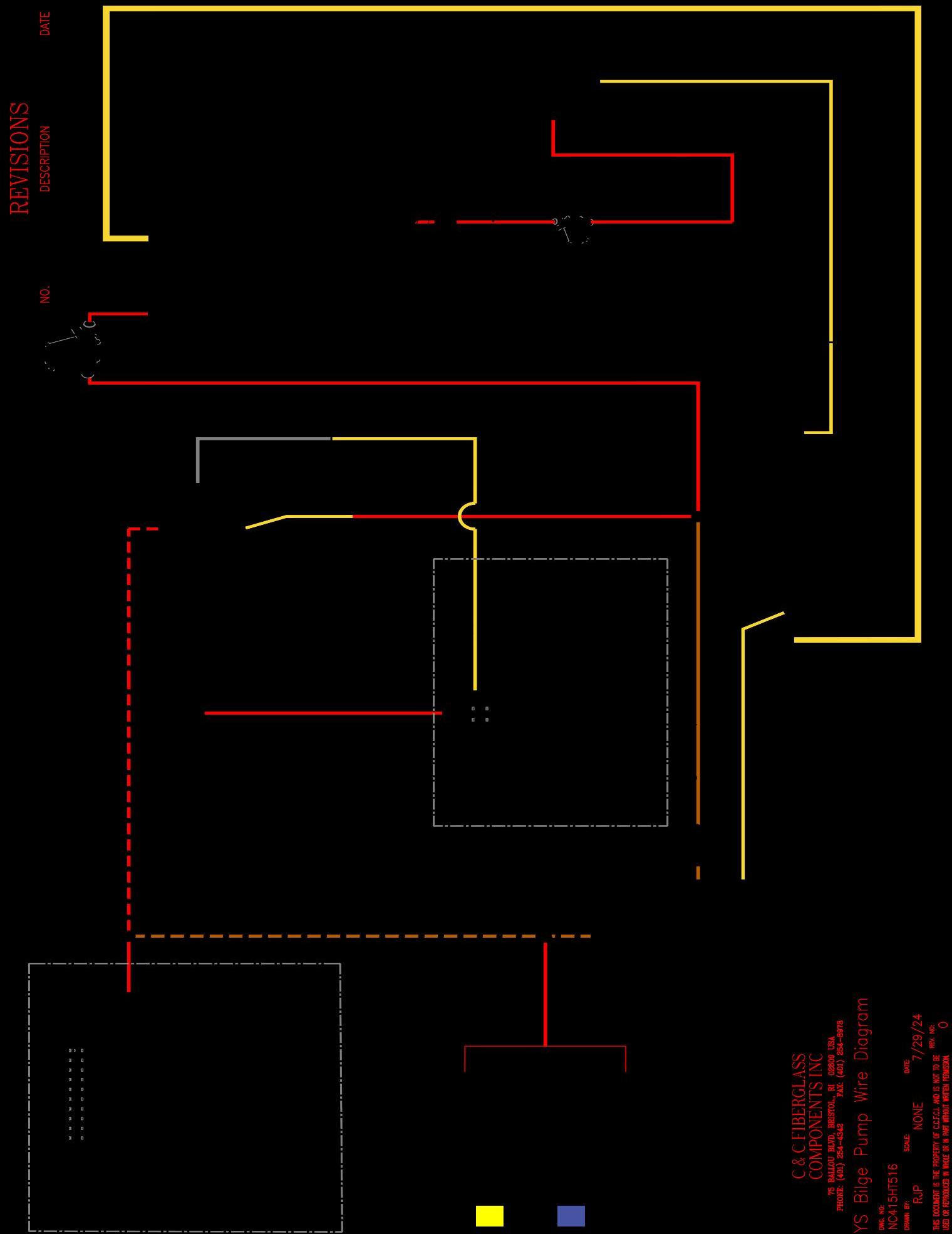
The electric bilge pumps are wired directly to the batteries and are always active as long as there is power in the batteries. Each circuit has a 15 amp in-line fuse located under the helm console. The pumps can be operated by manual switches or be set to the float switches from the helm station panel.
▪ BATTERIES
The batteries are sealed type which do not require any maintenance. If for any reason a battery needs to be replaced ensure that another is used as charging rates vary with different types of batteries.
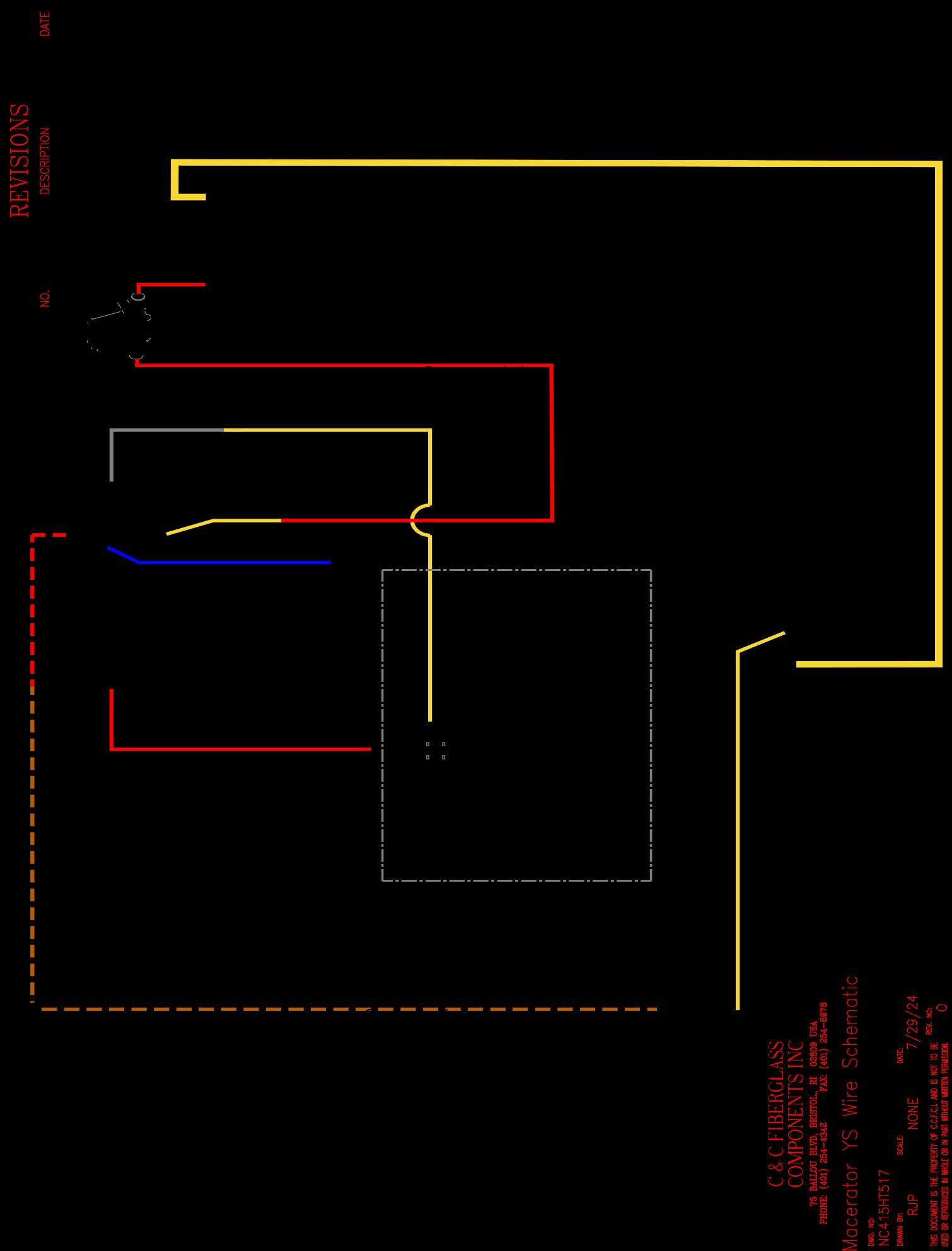
FISHBOX SYSTEM
Fish box System
Each Fish box is equipped with a macerator pump. The goal of the pump is to grind and pump fish box waste making it easier to discharge. The grinding process prevents clogs, creates efficient discharging, and can eliminate manual cleaning.
Procedure
1) Turn macerator on. The switch is located on the MFD,
2) This will grind and discharge any fish box waste.
3) When fish box waste is removed, the sound of the pump will change to a higher pitch noise.
4) It is good practice to use the raw water spigot to rinse the fish boxes completely while they are being emptied.
5) Turn off the switch on the MFD when the boxes are empty See Fig. 1
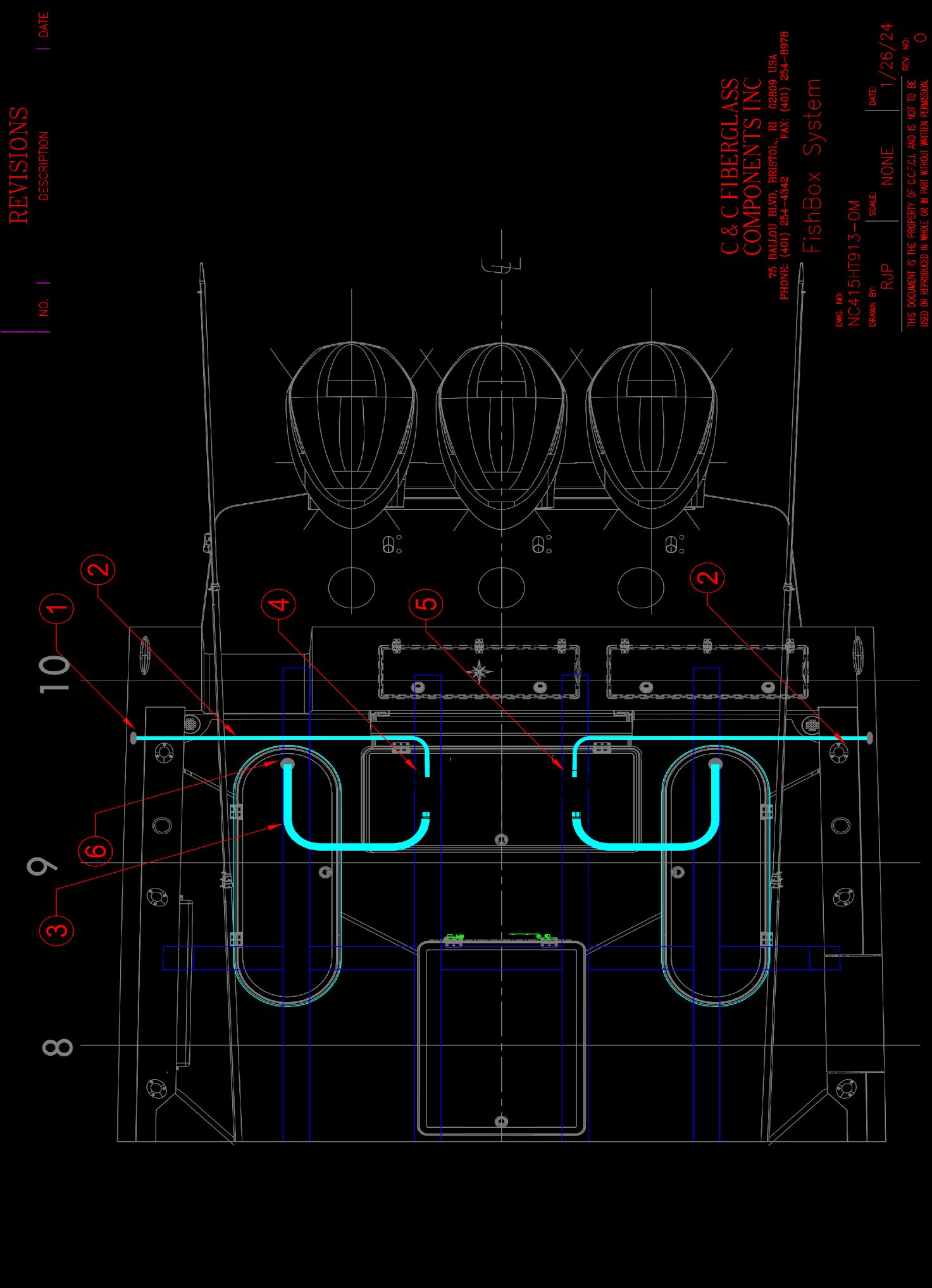
Fig. 1
PORT SIDE FISHBOX PUMP STBD SIDE FB PUMP
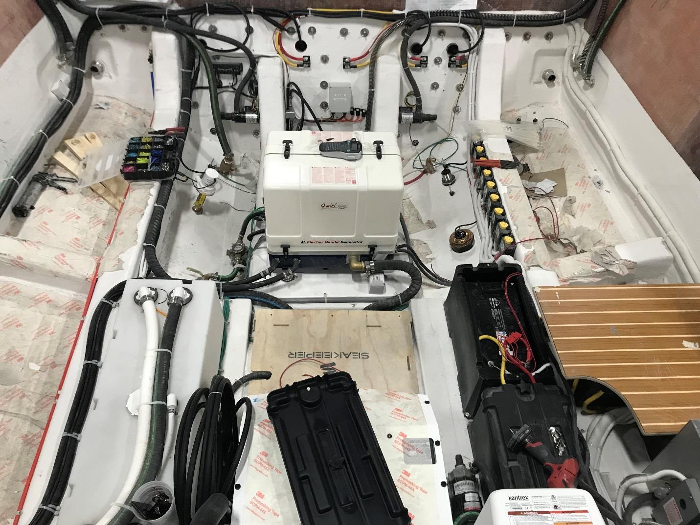
FISHBOX
FISHBOX PUMP LOCATION
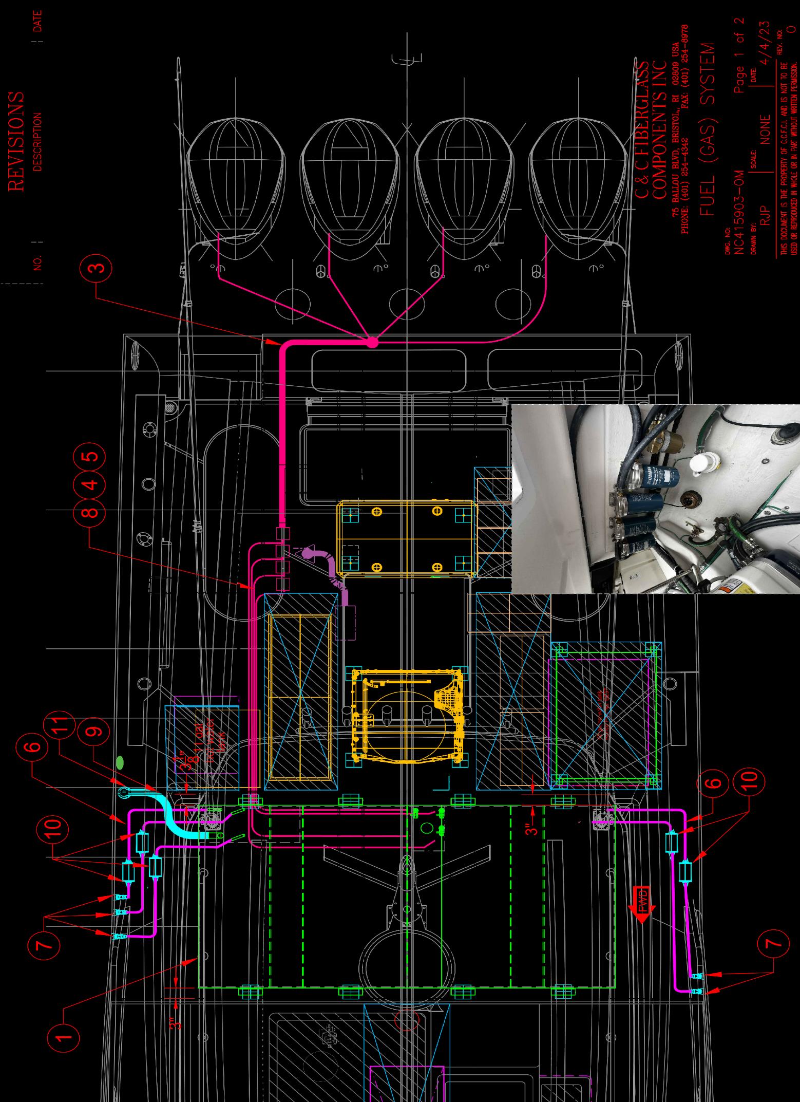
FUEL SYSTEM
Fuel System Operation
This system has been designed to meet the EPA regulations using certified components to limit the fuel vapor emissions. Your fuel system provides the following benefits:
Fuel Tank
Your boat is equipped with an aluminum fuel tanks that has a net capacity of 569 gallons and a useable capacity of 612 gallons. The fuel tank is different from the tank capacity marked on the tank from the manufacturer. The difference is the non-useable portion of the tank which results from the fuel in the tank that is below the pickup tube and the ullage area that has been incorporated into your tank. It is recommended that you follow all instructions regarding the filling of fuel tanks. Take time to read and understand all the fuel related information and warnings regarding gasoline and your boat, in the engine owner’s packet. Fuel tanks with levels less than 1/4 full can cause engine stalling problems due to fuel starvation or by allowing sediment and dirt to enter the fuel supply lines. Keep the tank full and monitor the fuel level often to prevent this from happening. Your tanks are painted with a Macropoxy by the fuel tank builder this protects the aluminum from corrosion and creating aluminum oxide. Your fuel tank is also equipped with check valve built into your fill.
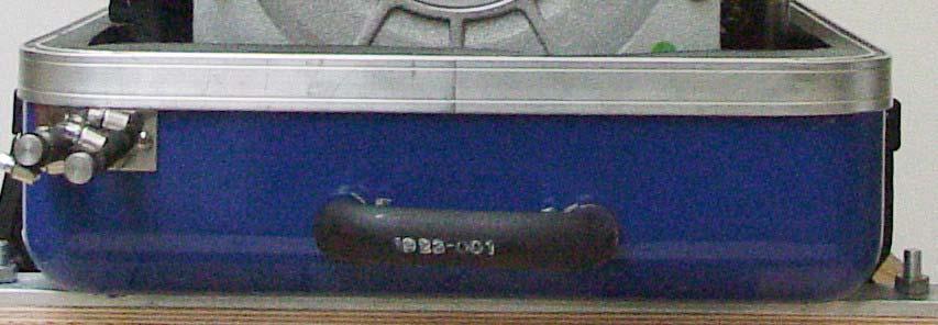
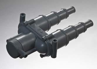
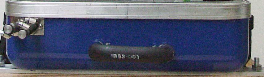
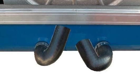
Fuel Vent
Multiple fuel tank vent/p-traps are located on the hull side next to the deck fill. The vent serves as an over pressure/vacuum release.
Filling the Tank
This fuel system is designed to automatically shut off the fuel nozzle when the tank is full, similar to an automotive fuel system. The tank is filled when the fuel fill nozzle has shut itself off the first time. Attempting to fill the tank past this point may cause some of the components to not function properly or malfunction.
Note:
During the first refueling event, the canister will heat up due to the carbon being activated for the first time.
NOTICE
Tank, hoses, and fuel pumps should be treated to help prevent the formation of varnish and gum. Temperature extremes will cause condensation to accumulate in an empty or partially filled fuel tank leading to fuel contamination and/or premature wear of your system. Fill the tank completely (100%) full and add fuel stabilizer and conditioner, following the manufacturer’s recommendations, to provide fuel stability and corrosion protection.
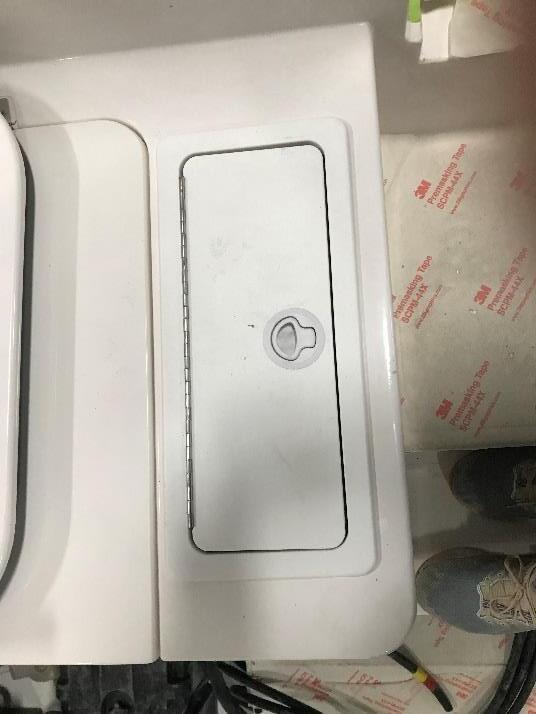
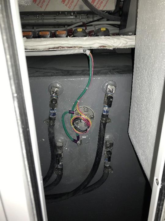
FUEL SHUTTOFF
To access the fuel shutoffs first open the starboard hatch located on the aft facing seat in the cockpit, there you will find all the shutoffs for each engine.
Starboard Hatch
Starboard Hatch opened
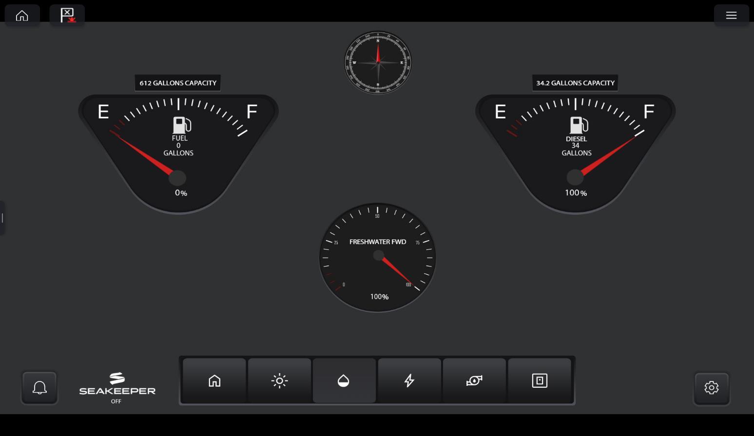
Yacht Sense Fuel Monitoring System on the MFD
Head Operation:
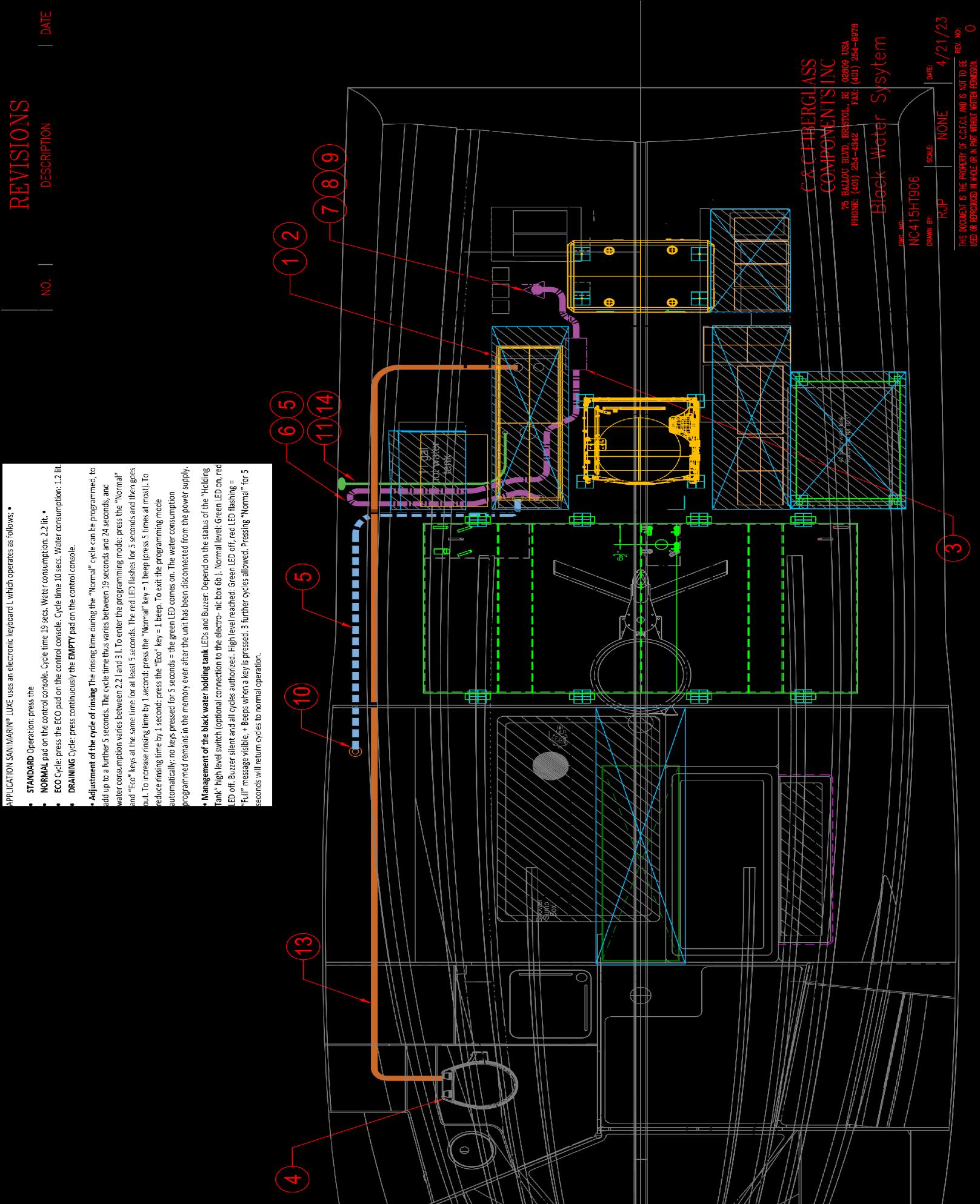
APPLICATION SANIMARIN® LUXE uses an electronic keyboard L which operates as follows; •
1: Turn HEAD SWITCH “ON” on the Yacht Sense page on your MFD , also tur “ON” the Freshwater Pump.
6.1 CONTROL PANEL OPERATION 6.1.1
Flush modes
Normal Cycle
Recommended for flushing solids and toilet paper. Press «NORMAL» button. The cycle is 15 seconds long.
Eco Cycle
Recommended for flushing liquids and small amounts of toilet paper.
Press «ECO» button. The cycle is 13 s long
Empty bowl Cycle
Recommended for removing water from the bowl.
Press «EMPTY» button until the water reaches its minimum level in the bowl.
Note: Remains of water are always present as its required for the trap. Press the «NORMAL» or «ECO» but- ton to return to normal operation.
Note: No use is possible when the black water tank is full (see 6.2 Management of the Black water tank)
6.1.2 Program mode
Adjustment of the rinsing cycle: The rinsing time during the “Normal” cycle can be programmed to increase up to 8 more seconds. The cycle will increase from 15 to 23 seconds.
To enter the programming mode: •
Press the «NORMAL» and «ECO» buttons at the same time for at least 5 seconds. The red LED flashes for 5 seconds and then goes off. READ MANUFACTURE MANUAL
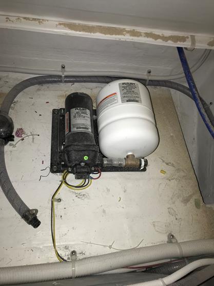
Step 1: Turn ON the Fresh Water Pump
Freshwater Pump Switch Location on the MFD
Fresh Water Pump located under STBD Side Bunk Hatch
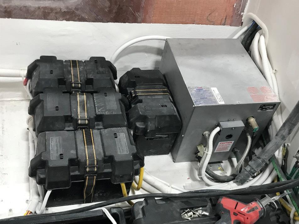
Step 2: Turn Hot Water Heater Breaker to ON position
Hot Water Heater Breaker Location
Note: Hot Water Heater will ONLY work with the Shore power or the Generator connected.
Hot Water Heater Port Side in Mechanical Room
HOT & COLD WATER SYSTEM
Hot Water Heater Maintenance
WARNINGS
Please note: When using electrical appliances, basic safety precautions must be followed to reduce the risk of fi re, electrical shock, or injury. This Whale® Heater must be installed by a qualified marine electrician.
CAUTION
Hydrogen Gas
• Hydrogen Gas can be produced in a hot water system that has not been used for a long period of time (generally 2 weeks or more). Hydrogen gas is extremely flammable.
• To reduce the risk of injury under these conditions, prior to using electrical appliances, the user must ensure that the hot water faucets in the galley are opened for several minutes until there is a smooth water flow. If hydrogen is present, there will be an unusual sound similar to air escaping through the pipe as the water begins to flow.
• Run the faucet for several minutes until there is a smooth water flow to release all the gas.
•WARNING Do not smoke or have any open flame near the faucet when checking for hydrogen.
Galvanic Corrosion • To help prevent possible damage due to electrolysis, installing a galvanic isolator is recommended. • Galvanic corrosion is not covered under warranty.
Corrosion
• Corrosion may occur in your Water Heater due to high current or in areas of hard water with a higher concentration of dissolved salts.
• This Water Heater is therefore supplied with a sacrificial anode to prevent rapid corrosion.
• Anode rods preserve the life of a Water Heater by corroding themselves instead of the heater.
• These anode rods are easy to replace and must be checked for corrosion every 6 months. Please see Maintenance (Section 10) for more information.
• Please note - Zinc anodes do not prevent corrosion; magnesium anodes are recommended.
Before using this Water Heater please read the instructions for use:
• Do not operate heater unless it is completely full of water. If heater has been operated without water and fails to work, follow the switch reset instructions in Section 9.ii.
• The 12 V dc. Water Heater can only be operated when the engine(s) are running at cruising speed to ensure batteries remain fully charged. Alternatively, the Water Heater can be connected to a dedicated 12 V battery.
• If the boat is connected to the dockside water system, ensure that the system is turned off at the dock when not attended. Also ensure that a pressure regulator is fitted to the vessel.
• Heat up times are dependent on your installation and other variable factors including initial temperature of the water, power available and ambient temperatures.
• The water temperature cannot be adjusted. It is automatically set to approximately 140°F / 60°C to prevent bacteria growth.
• To avoid scalding, the temperature of hot water supplied to faucets and showers must be controlled via a thermostatic mixer valve as per ABYC H-23 standards (See section 8.vii).
• Do not use water from the Water Heater as drinking water.
Instructions for Use
1. Fill the water system and completely fill the Water Heater tank according to boat or pump manufacturer’s instruction, purging all pipes and outlets. NOTE - Depending on the boat system size, it may take time to fill and deliver a smooth flow of water from hot and cold outlets.
NOTE This water heater is not designed to run dry. Running the heater dry will result in damage to the system.
2. Locate and switch ‘ON’ the remote electrical switch for your water heater, if a running light is installed this will illuminate.
3. Typical heat up times for this Water Heater are as follows:
4. The running light will remain lit until the water has reached 140ºF / 60ºC, then cycle on and off as the temperature is maintained. Once switched off, the Water Heater will retain usable hot water for up to 10 hours.
NOTE If the running light cuts out within the first 30 minutes of operation, turn off the Water Heater and refer to Reset Instructions
5. Switch the remote electrical switch ‘OFF’ prior to turning off engines and ensure it remains off when you restart the engine.
6. The Temperature and Pressure Valve may weep during initial operation - this is normal and the valve will seal itself with use.
9.ii Reset Instructions If the Water Heater has accidentally been operated without water and fails to work, the Water Heater is equipped with a high limit switch which can be manually reset. If the limit switch activates, proceed as follows:
• Turn power off at main power panel and remote switch.
• Ensure that the Water Heater is filled with water by filling the fresh water tank and running a hot tap until a smooth flow is achieved. • Remove wiring access cover and fibrous dielectric paper
• Depress red button on high temperature limit switch.
• Replace cover and turn power on.
• If temperature limit switch re-activates, contact Whale® Support (section 13)
MAINTENANCE
This Whale® Water Heater is designed to only require minimal maintenance. WARNING: Before servicing, turn off all power and drain the system. NOTE: Do not repair or replace any part of the Water Heater unless specifically recommended in the installation manual. For technical support contact Whale® Support (section 13). Annual Checks
• Whale® advise an annual boat electrical system check that must be completed by an marine electrician. Optimal Performance • Ensure this product is regularly cleaned to ensure consistent performance.
• To clean and sterilize the inside of the Water Heater, use diluted sterilizing fluid and fully rinse through with clean fresh water afterwards.
• The outside of the appliance should not require cleaning. If it does, turn off all electrical supply at breaker and wipe down with a damp cloth only. Allow the Heater to fully dry prior to reconnecting the electrical supply. NOTE Do not use abrasive cleaners on any Whale® Water Heater
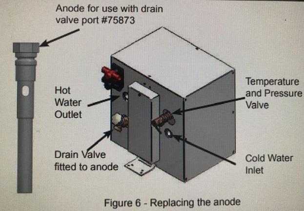
• If de-scaling is required, this can be done using a de-scaling solution. Fully flush out the Water Heater after de-scaling. Replacing the Anode, The Whale® replacement anode is Part # SK3S360EW.
• Drain tank fully and turn off power.
• To replace the anode, remove the drain valve and the pre-installed sacrificial anode (figure 6) and screw the new anode and drain valve back in its place.
• Whale® recommends checking the anode regularly for signs of corrosion. If you have any concerns about rapid corrosion, please contact Whale® Support (Section 13).
• Temperature and Pressure Valve Cold Water Inlet Drain Valve fitted to anode Hot Water Outlet Anode for use with drain valve port #75873 Figure 6 - Replacing the anode
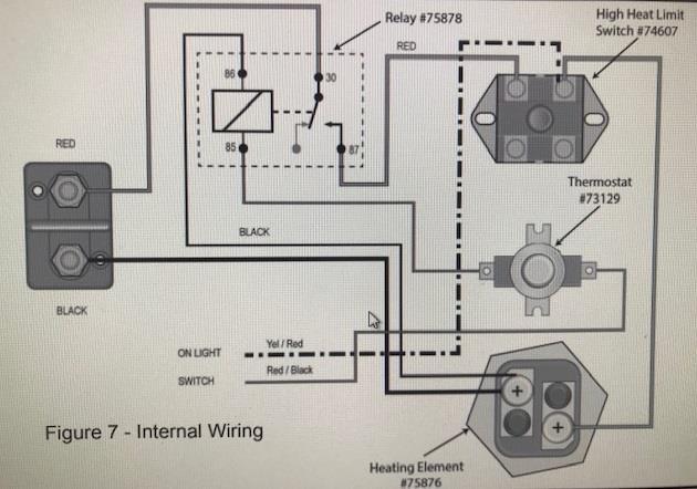
The following service items are available for this Water Heater from Whale® (Figure 7).
Heating Element #SK3S360EW
Relay #75878 High Heat Limit Switch #74607
Temperature and Pressure Valve #74659 Magnesium
Anode #75873
Thermostat #73129
NOTE: Figure 7 depicts the internal wiring of this Water Heater. For advice on servicing any of the highlighted components please contact Whale® Support (Section 13) or a marine electrician.
WINTERIZING
Note - If water is allowed to freeze in the system, serious damage to the pipe work and pump may occur. Failures of this type will invalidate warranty. To best avoid this damage, completely drain the water system.
WARNING - The power source must be turned off before draining and refilling this Water Heater.
1. Drain the complete freshwater system either using the pump or a drain valve.
2. Open all the faucets (including the Water Heater drain valve) and allow pump to purge the water from the system, and then turn the pump off.
3. Disconnect the pump and turn on to purge into an adequate basin. Only reconnect the pump when water system is to be used.
4. Remember to leave all faucets including the Water Heater drain valve open to avoid any damage (except for Whale Twist™ Deck Shower if installed).
HOT & COLD WATER SYSTEM
TROUBLESHOOT:READ YOUR OWNERS MANUAL
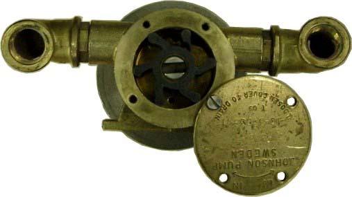
Fresh Water System Maintenance
• Very little maintenance is required for the fresh water system, other than annual disinfecting and winterizing. Periodically check the entire system to assure that the hose connections, tube fittings, electrical connections and mounting bolts are properly secured, and free of chafing.
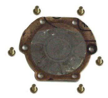
• Periodically check the in-line strainer attached to the pump, and clean if necessary. The system should be run at least every other month to maintain the pump’s impellers in a stable operating condition.
REFER TO THE MANUFACTURER’S MANUAL IN YOUR OWNER’S MANUAL PACKET FOR COMPLETE INSTRUCTIONS AND WARRANTY.
The information contained in this appendix provides supplementary data about disinfecting a potable water system.
AP 1 A SUGGESTED METHOD OF DISINFECTION
Perform the following steps in the order indicated:
a.Flush entire system thoroughly by allowing potable water to flow through it
b.Drain system completely
c.Fill entire system with a chlorine solution having a strength of at least 100 ppm, and allow to stand for one hour (see AP TABLE 1) Shorter periods will require greater concentrations of chlorine solution.
d.Drain chlorine solution from entire system.
e.Flush entire system thoroughly with potable water.
f.Fill system with potable water.
AP TABLE1shows the amount of disinfecting agent required for various quantities of 100 ppm chlorine solution.
AP TABLE 1-Chlorine Concentrations
Amount of chlorine compound required for 100-ppm solution.
Gallons Chlorinated High Test Calcium Liquid Sodium Of Lime 25% Hypochlorite 70% Hypochlorite 1% Solution(ounces) (ounces) (quarts) 5 0.3
Reprinted from ABYC Appendix H-23.
Step One:
Open all faucets and turn on the freshwater pump. Allow the faucets to run until the freshwater tank is dry, then close all the faucets and turn the pump off.
Step Two:
Pour four to six gallons of West Marine Pure Oceans non-toxic antifreeze or equal into your boat’s potable water storage tank.
Step Three:
Turn the pump on and open the hot water fixture farthest from the pump. This will cause antifreeze to flow to the hot water heater and to the hot water fixture. When you see antifreeze coming out of this fixture, turn it off. Next, open the corresponding cold water fixture, wait until you see antifreeze coming out, then turn it off. Repeat this procedure for all fixtures on the boat, working your way back to the fixture closest to the pump. Don’t forget the shower. When finished, turn the pump off.
By following the procedures outlined above, you will assure that your boats freshwater delivery systems will function properly in the spring.
Winterizing the Water System
Use a non-toxic propylene glycol, like West Marine Premium Antifreeze for Engine and Water System Winterization. For northern regions where the mercury can drop below zero, we recommend antifreeze with a freeze rating of at least -100°F. Why use -100°F antifreeze when the temperature never goes below -50°F? The answer is that what goes into the system as -100°F antifreeze, does not come out as -100°F antifreeze. There is always some residual water that lowers the concentration of antifreeze, so the resulting freeze point may be much higher than the rated temperature. The small cost difference between the -50°F, -60°F and -100°F antifreeze is a bargain for the peace of mind you get knowing that your systems will be safe, no matter what the weather. For greater detail on the antifreeze we sell see Antifreeze 101
Best Practice for Antifreeze Disposal
One other point: Even though West Marine propylene glycol antifreeze is non-toxic, best practice dictates that you not discharge it on to land, into storm drains or directly into the water. After use, dispose of used antifreeze in a manner consistent with federal, state and local regulations.
LIVEWELL OPERATION
Livewell Operation
The baitwells are located aft at the transom. The baitwell is filled via the aerator spigot. The water is supplied by the baitwell pumps located in the bilge. The baitwell is filled by screwing in the cap into the fitting at the bottom of the baitwell. To drain the baitwell simply unscrew the cap until the drain holes in the threaded fitting are exposed. The baitwell drains overboard unassisted to the port side at the boot top.
Your Baitwell water is supplied with a 1600GPH Tournament Series Live Well-Baitwell pump 209B. Follow Operation procedures below.
Operation:
1. Open Seacock
2. Open Aerator and turn pump ON see Fig 1 for pump switch
3. The tank will fill
4. Leave pump on for continuous exchange of water
5. NOTICE: The seacock MUST be in the OPEN position running the pump dry may cause damage to the pump.
6. When system is not in use close seacock. There is NO built in check valves when underway. Pressure will build up in the lines.
7. Reducing the water flow at the seacock or aerator will not damage the pump.
8. Leaving the pump in the on position and the aerator closed will eventually for long periods of time will damage the pump.
Livewell/Raw Water System Winterization
Drain the livewell. Ensure that all water is removed from the drain hose. Remove the fill hose from the pump in the bilge and drain the water from the hose. Replace the hose on the pump and tighten the two clamps.
Fig. 1 MFD Pump Switch Screen Shot
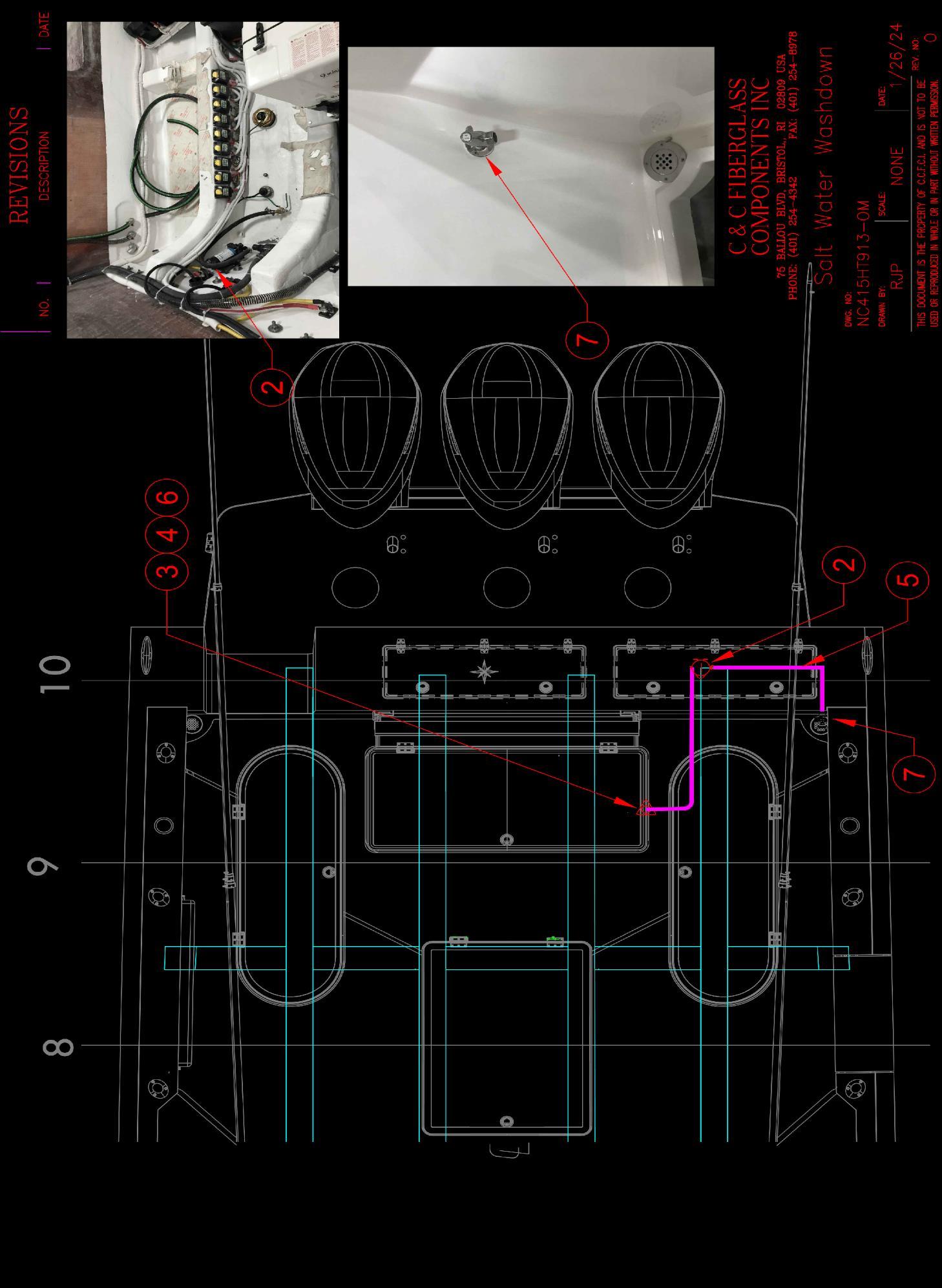
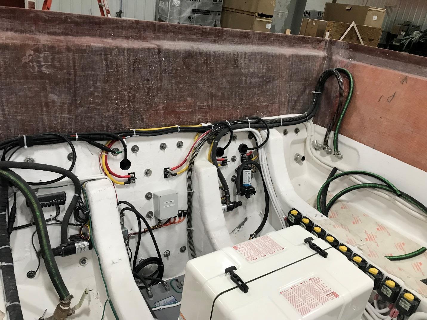
SALT WATER WASHDOWN SYSTEM
Saltwater Washdown
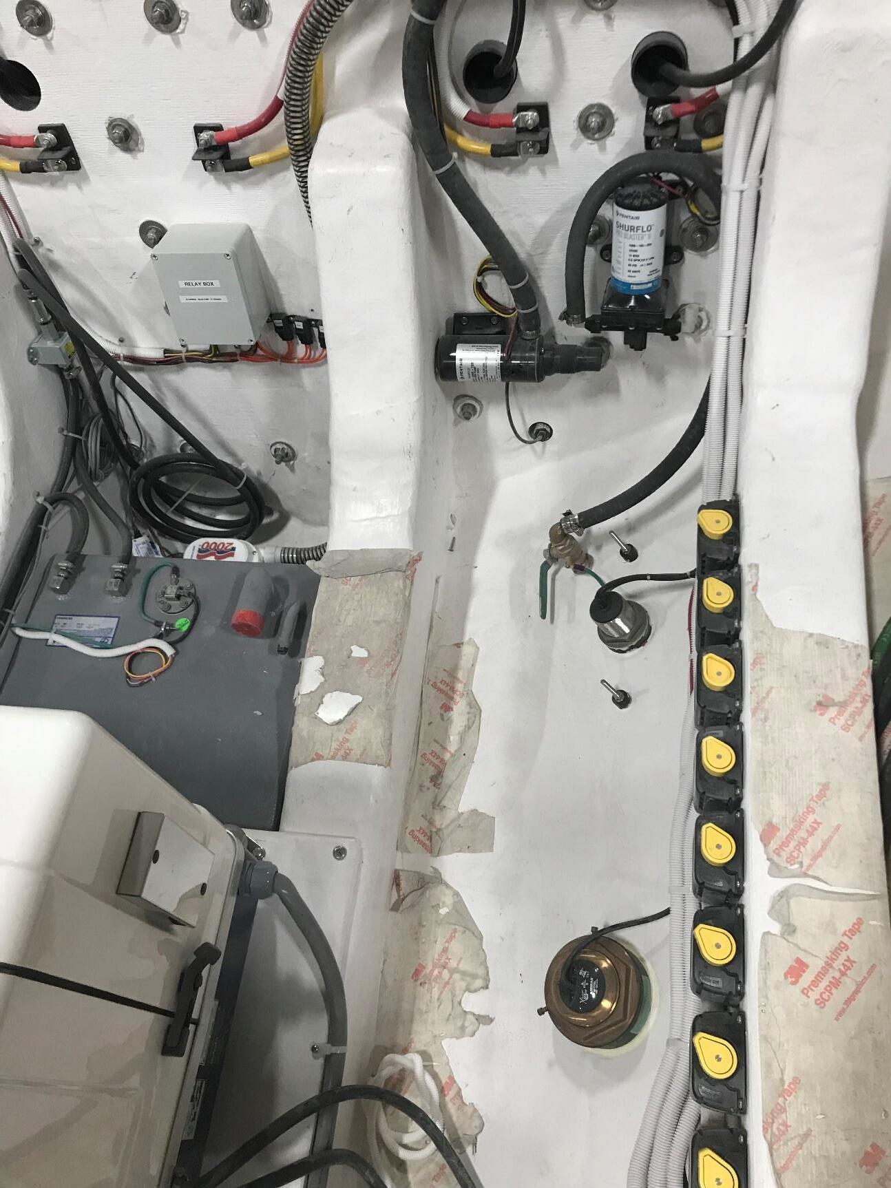
The saltwater washdown spigot is located on the port side corner of the transom. The saltwater is fed from a pump, located in the bilge on the port side aft between the stringers. The saltwater pump is located aft in the bilge pump compartment and labeled.
NOTE:
1: Operator must open intake seacock to use Saltwater Washdown.
2: When not in use, the power switch should be in the OFF position and seacock valve closed. See Fig 1
Fig. 1
Saltwater washdown pump location
Saltwater washdown seacock
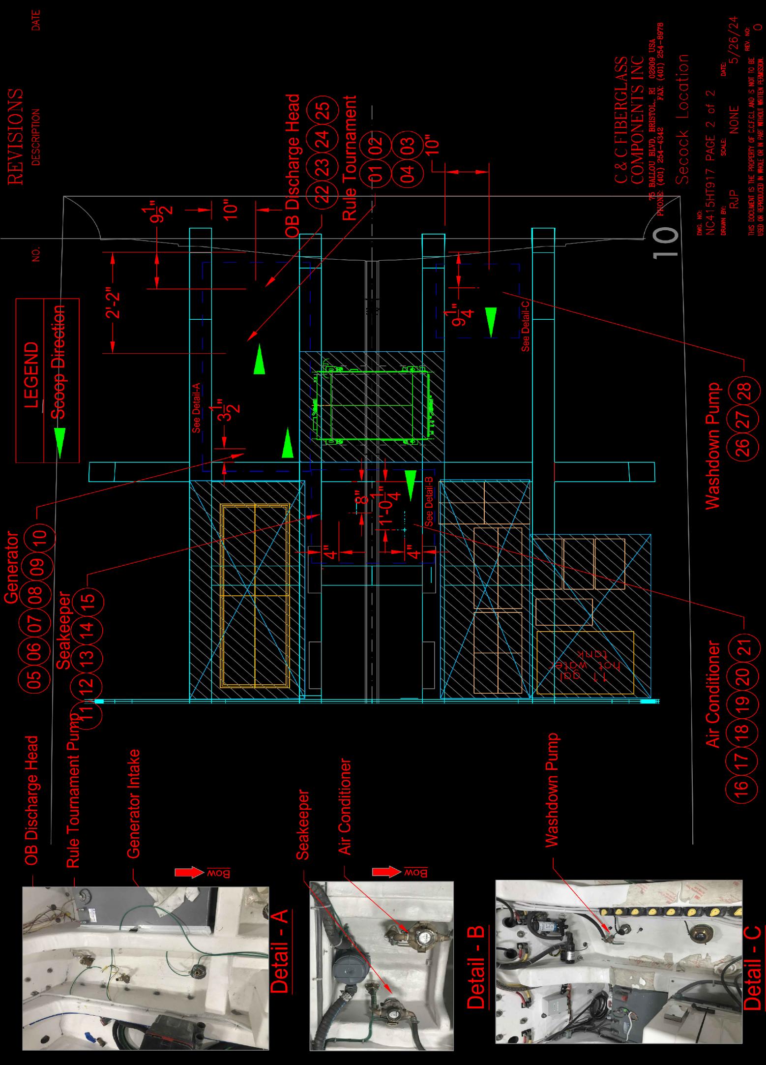
SEACOCK
The materials and workmanship of your NorthCoast 315 Hard Top will insure many years of operation and enjoyment. However, there are numerous steps you can take to keep your boat in top condition. Failure to take certain of these steps may result in shortened life span of certain equipment and may in certain cases, void the warranty.
Much of the equipment installed on your boat is separately warranted. Please refer to the individual OEM manuals for care and maintenance instructions, along with proper registration.
The easiest and perhaps most important regular maintenance step is to simply wash down the boat after each use with fresh water. This is of primary importance when operating in saltwater, but applies to freshwater use as well. Make sure to wash down the engine cowlings, canvas and cushions, rails, hull and deck.
Gelcoat
Regular cleaning and waxing will help preserve the finish on your boat for many years. The frequency at which this is needed will depend on your seasonal usage, area of operation and color.
• Use a mild detergent wash with fresh water.
• Rinse away all detergent residue.
• Do not use harsh or abrasive cleaners or other compound containing chlorine or ammonia.
• Do not use acetone or other ketene-based solvents. Use denatured alcohol or kerosene and rinse the area being treated immediately. Wax the gelcoat surfaces with a high-grade wax, making sure to buff out all areas where wax has been applied.
Inevitably you will get scratches on the gelcoat surfaces.
• Water sand minor scratches with #600 paper, then buff with polishing compound or equivalent.
Scratches that penetrate to the fiberglass substrate should be dealt with immediately. This is particularly important on scratches below the waterline. Your dealer or other industry professional best handles these repairs.
Whether operating in fresh or saltwater, marine growth is a problem. It will degrade performance, fuel economy and in severe instances can damage the gelcoat surface.
• Use a high-grade anti-fouling bottom paint that conforms to the regulations for operation in your boating area.
• Regular running of the boat at high speed when appropriate will rid the bottom of light growth.
• Regular washing of the bottom surfaces is recommended.
Other Exterior Components
Windows and Hatches
The clear surfaces of these components require the most attention. Clean metal frames per the instructions below for stainless steel and aluminum. Rinse all acrylic surfaces with clean fresh water. DO NOT rub the surface in any way. Clean acrylic surfaces with mild detergent regularly (after rinsing). Rinse again and pat dry with a clean chamois or cotton towel.
Grease and adhesives may be removed with kerosene, hexane or white gas. DO NOT use any other solvents or removal agents.
Stainless Steel and Aluminum
All metals used on your NorthCoast are selected for their resistance to corrosion. However, none are corrosion proof.
What appears to be “bare aluminum” is actually anodized. When welded, the anodizing breaks down due to heat. Make sure to keep the weld joints waxed for best protection. See below for other general care instructions.
Certain structures may be “white aluminum”. This is actually a powder-coated surface. This provides optimal protection for weld joints and lends a clean appearance to the metal. Follow the general care instructions below.
Stainless Steel structures are highly corrosion resistant without the anodizing or powder-coating as in aluminum. However, welded areas are again more susceptible to corrosion. Keep these clean and waxed as with aluminum.
• Clean all metal components frequently with fresh water.
• Protect all surfaces with wax.
• Remove rust spots promptly with metal cleaner.
• Do not use coarse abrasives such as steel wool, soap pads, etc.
• Do not clean with acids or bleaches.
• Maintain powder-coated surfaces in a similar fashion to gelcoat surfaces.
Canvas
Clean with soft bristle brush and fresh water. Do not use detergent soap. Use a neutral soap when needed. Remove bird droppings and other stains promptly before they set in and degrade the performance of the material.
Vinyl
Wipe down regularly with mild soap and fresh water. Do not use any special cleaners or solvents.
CARE & MAINTENANCE
Corrosion
When operating in saltwater for extended periods, check the transom mounted grounding anode for significant de-gradation. Replace at 50% level. Check the sacrificial anodes in the engine. Check all metal thru-hull fittings when hauled out. Ensure that the engine is tilted full up when the boat is left moored or docked.
Significant/frequent signs of pitting or other metal degradation may be indicative of a corrosion problem either with your vessel directly or due to other stray currents present in the marina or the marina electrical system.
Winterization, Storage and Commissioning
Proper storage of your boat is equally important as in season maintenance. Some recommended steps are provided to assist in this. Your local situation may require further measures.
Winterization and Storage
• Orient the hull so any water from rain, snow and condensation drains aft.
• Remove the garboard drain plug.
• Drain all water from water systems, including the water tank, hoses and fittings.
• Make sure the fuel tank is full. You may want to add a stabilizer to prevent algae growth.
• Ensure that bilge pump system is drained.
• Treat all uncoated metal parts with rust inhibitor.
• Winterize the toilet system per manufacturer’s instructions.
• Empty holding tank.
• Remove batteries and store in warm, dry environment. Do not store on concrete floor.
• Winterize engine(s) per manufacturer instructions.
• Cover with shrink wrap or store in covered area.
• Ensure that the boat is properly blocked. If stored on a trailer, block this up to unweight tires.
NORTHCOAST BOATS WARRANTY POLICY
C & C Marine Inc.
Manufacturer of NorthCoast Boats™ 75 Ballou Blvd. Bristol, RI, 02809
Tel: 401-254-4342 Fax: 401-254-8978
NORTHCOASTBOATS™
LIMITED WARRANTY- RECREATIONAL BOATS
1. The “Federal Boat Safety Act of 1971" requires all boat manufacturers to maintain a record of all first retail purchasers and their current addresses for the purpose of notification in case of defective parts or equipment or in case of noncompliance with standards or regulations set forth by this act. Under the act, the failure to complete and return your factory warranty card for our records will waive your right to notifications of defect and/ or repair at manufacturer’s expense.
2. Hull Warranty: C & C Marine, Inc. (Manufacturer of NorthCoast Boats™) warrants to the first purchaser and any subsequent owner that the hull and stringers will be free from structural defects in materials and workmanship for a period of TWELVE (12) YEARS from date of purchase from dealer or manufacturer subject to the conditions set forth below.
3. One-year components warranty: C & C Marine, Inc. warrants to the purchaser or owner that for one year (1) after the date of purchase, all boat components manufactured by C & C Marine, Inc. shall be free from defects due to material or workmanship under normal noncommercial use.
4. Exclusions:
A.) This warranty will apply only to boats used in normal recreational boating activities. Boats used in any governmental, commercial or revenue producing activity of any kind, including but not limited to charter or rental fleets, are excluded from coverage under this warranty.
B.) Parts or accessories that were dealer or owner installed items are the responsibility of the dealer or owner
C.) This warranty does not apply to cosmetic defects, including but not limited to, gelcoat cracking, chalking, crazing, discoloration, yellowing, blistering, nor graphics or coloration problems.
D.) Fiberglass blistering attributable to water penetration of the fiberglass (osmosis) is specifically excluded from this warranty coverage.
E.) This warranty does not apply to problems caused by improper maintenance, abuse, vandalism, lack of maintenance, improper storage, improper hauling or transport,
WARRANTY
normal wear and tear, misuse, neglect, accident, corrosion, electrolysis, improper operation or Acts of God.
F.) Windshield breakage and/ or leakage is not covered by this warranty.
G.) Fuel contamination of any kind is specifically excluded from this warranty.
H.) Hulls modified in any way or hulls on which the engine installation has been modified in any way are not covered by this warranty.
I.) This warranty does not cover tears, cracking, fading, discoloration, or mildewing of curtains, cushions, tops, headliners, or other fabric or upholstered items.
J.) This warranty does not cover components not manufactured by C & C Marine, Inc., whether or not warranted by the other manufacturer, even if installed by C & C Marine, Inc., including but not limited to engines, propellers, appliances, and air conditioning. Warranties provided to generator sets, controls, electronics, batteries, appliances and air conditioning. C & C Marine, Inc. by component manufacturers shall be passed on to purchaser to the extent that such transfer is permitted by manufacturer.
K.) Haul out, launch and transportation charges.
L.) The cost of removal or reinstallation of parts or disassembly of units to repair or replace components covered by this warranty.
M.) Damage caused by an improper trailer or mismatching of a NorthCoast Boat™ to a trailer, failure to properly secure the boat to the trailer, or failure to use a lower unit support device when transporting the boat.
5. This warranty shall not apply to any boat that has been overpowered according to the maximum manufacturer recommended engine horsepower specifications on the capacity plate affixed to the boat, if one shall appear on said boat.
6. Speeds, fuel consumption, weights and other characteristics of performance are strictly estimating and therefore cannot be and are not guaranteed. Any oral statement or printed statement regarding any performance characteristic of the boat or its components shall be considered an estimate only and shall not be relied upon as express warranty as a basis of the bargain for the boats or its components.
7. C & C Marine, Inc. reserves the right to improve its boats at any time through modifications in design, use of new materials and / or incorporation of new methods of manufacture without any obligation to incorporate such changes into boats of prior manufacture.
8. C & C Marine, Inc.’s obligation under this warranty is limited to repairing or replacing, at our option, hulls that C & C Marine, Inc. determines to be structurally defective. This
WARRANTY
is your sole and exclusive remedy.
9. This warranty and the rights and remedies under it is exclusive and is given in place of all other warranties, whether expressed or implied, including any implied warranty of merchantability or fitness for particular purpose, whether arising by law, custom, conduct, or usage of trade. Purchaser’s remedies shall be limited as stated herein and C & C Marine, Inc. shall not be liable for any incidental, consequential or indirect damages or losses resulting from defects.
10. This limited warranty gives purchaser specific legal rights. Purchaser may have other rights which may vary from state to state. In the event that implied warranties are found to exist under the laws of a particular state notwithstanding the exclusions contained herein, the duration of any such warranty shall be limited to the duration of the applicable limited warranty stated herein.
11. The selling dealer is not an agent of C & C Marine, Inc. or a co- warrantor and is not authorized by C & C Marine, Inc. to amend or modify this warranty in any manner.
12. Warranties
In addition to the NorthCoast Limited Warranty, each component and/or system on your boat has its own warranty that can be found with the specific information and manual for that component. These are included with your owner’s information packet. Please locate, read, and retain the individual warranties.
OWNERS RIGHTS AND RESPONSIBILITIES
12. The owner must notify C & C Marine, Inc. or an authorized C & C Marine, Inc. dealer of any defect in material or workmanship within thirty (30) days of discovery.
13. C & C Marine, Inc. reserves the right to require that all repairs and / or replacements be done by our factory in Bristol, Rhode Island., the authorized dealer who originally sold the boat, or at a repair facility that we choose. Boats or parts will be transported to the selected repair facility at the owner’s expense. Haul out fees are the responsibility of the owner. Reimbursement to repair facilities under the warranty will be based on a rate and schedule established by C & C Marine, Inc.
14. In no event will C & C Marine, Inc be liable for any incidental, special, or consequential damages or for any other loss, damage, or expense of any kind, including loss of profits or enjoyment.
WARRANTY REGISTRATION
15. Proper warranty registration is required to validate the warranty. The warranty registration must be filled out by the first purchaser and the authorized dealer at the time the boat is purchased. This warranty shall not be valid unless that factory warranty paperwork is properly executed and mailed within ten (10) days of the purchase of the NorthCoast boat. Failure to register properly could void the warranty. This warranty registration is for recreational boats only.
TRANSFER OF WARRANTY
16. Coverage remaining under the limited warranty period may be transferred to a subsequent purchaser within the applicable limited warranty period. Any subsequent owners during the warranty period must provide C & C Marine, Inc. In writing, the HIN, name and address or new owner, and the name of name of the previous owner. A request for transfer must be made in writing to C & C Marine, Inc., 75 Ballou Blvd., Bristol, RI 02809 within 15 days of transfer.
Please send a copy of the prior owner’s information. The new owner and purchaser agree to all items and conditions of the warranty. Only the unused portion of the warranty will apply to the new owner. The new owner must fill out the Transferable Warranty Form.
NorthCoast Boats
Warranty Registration Form
IN ORDER TO REGISTER WARRANTY, THIS FORM MUST BE COMPLETED AND SENT WITHIN 10 DAYS OF DELIVERY TO: C & C MARINE, INC. 75
* Buyer acknowledges by his/her signature that he/she has read the warranty statement and agrees with the terms and conditions stated therein. The buyer also acknowledges the receipt of a copy of this warranty at the time of delivery.
*New Buyer acknowledges by his/her signature that they have read the warranty statement and agrees with the terms and conditions stated within. The New Buyer acknowledges the receipt of a copy of this warranty at the time of sale.
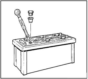
RECOMMENDED
RECOMMENDED TOOLS FOR ONBOARD MAINTENANCE
• Screw Drivers
a. Straight - stubby - offset - jewelers set
b. Phillips - stubby - offset - jewelers set
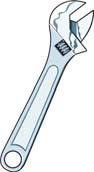
• Set Adjustable Wrenches
• Set Open/Box standard & metric to 1" and 19 mm
• Socket Set standard & metric to 1" and 19 mm
• Channel Locks: 12" and largest available
• Pliers
• Needle Nose Pliers - small and large
• Wire Strippers/Crimps
• Vise Grips - large and small
• Utility Knife
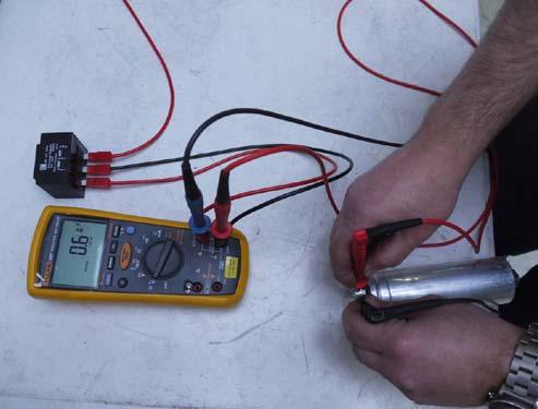
• Multi-Meter
• Spare Parts Kits
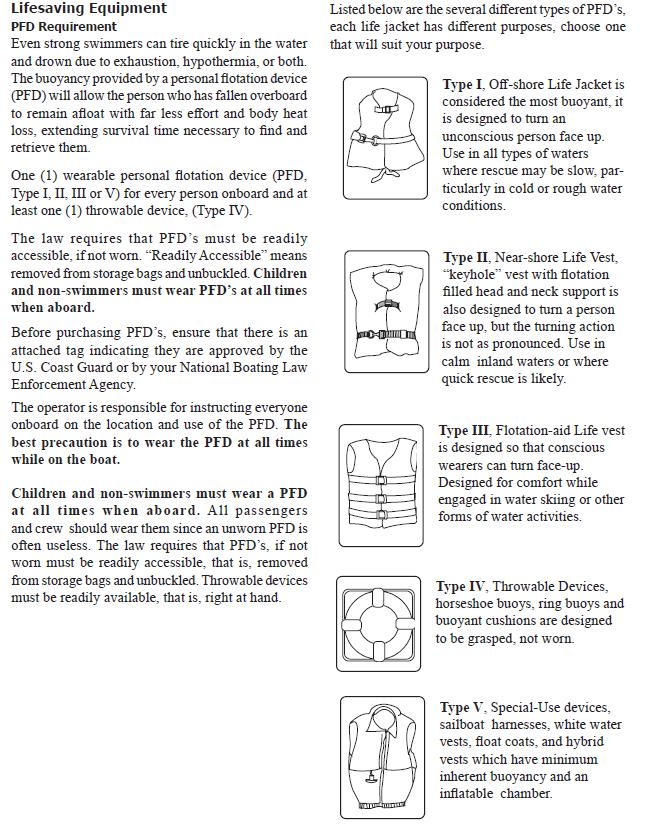
TYPICAL LIFE JACKET LABEL
SAFETY
Owner responsible for mounting 5 step safety ladder in a canvas bag dealer supplied
CONSTRUCTION DETAILS
• HULL AND DECK MATERIALS
• TECHNOLOGY
NorthCoast uses some of the most advanced technology in the marine industry in the design and construction of all NorthCoast. Only top quality, top performance materials which have been thoroughly tested are used.
• GELCOAT
To protect the laminate from the environment, all NorthCoast utilize Isophthalic (ISO) gelcoat. ISO gelcoats yield a denser, more frequently branched molecular network which inhibits migration of water molecules. Because of their structure, these gelcoats offer superior resistance to moisture penetration, blistering and fading. They are formulated to yield slightly more flexibility than most gelcoats which helps to resist cracking. Tests also indicate that ISO gelcoats produce the highest, most durable gloss finish, and retain it despite severe environmental exposure.
• GLASS FIBERS
High performance glass fabrics are used throughout the sandwich-type laminate. They offer superior strength and stiffness when compared to conventional cloth and woven roving materials used by many other builders. In high stress areas, bi-axial fabrics, which can be oriented to yield maximum strength and stiffness are used. These fibers require less resin and therefore, produce stronger, lightweight structures.
• VINYL ESTER RESIN
A special vinyl ester resin is used as a barrier behind the gelcoat to further resist moisture penetration. By excluding moisture, blistering cannot occur. The vinyl ester resin is also resilient like the gelcoat to increase crack resistance. The vinyl ester resins, in combination with ISO gelcoats and carefully selected fibers, produce the most blister resistant hulls available today.
• POLYESTER RESIN
A high quality polyester resin is used to complete the rest of the laminate. Selected for its compatibility with the high-performance fabrics used, this resin provides a high-strength, durable laminate, resistant to cracking and fatigue. Again, the correct balance of properties between each component is designed to assure that the high strength and stiffness will be retained throughout the life of your vessel.
• HULL AND DECK CONSTRUCTION
• SANDWICH DESIGN
Sandwich construction is used in all NorthCoast decks to produce stronger, lighter, faster performance cruising boats. A fiberglass sandwich functions similarly to an "I" beam. "I" beams are used for construction because they make the most efficient use of materials based on structural criteria and reduce overall weight. The inner and outer skins of the sandwich function in the same ways as the top and bottom flanges of the "I" beam, and the core functions similarly to the web of the "I" beam. This means lighter decks can be produced which are actually stiffer and stronger.
• SOLID HULL BOTTOMS
Peace of mind comes with not using core in our hull bottom construction. While other competitors core their bottoms, they are exposing themselves to long-term problems, with any significant impact through the thin external laminate this will allow water to penetrate and saturate the core and will act as a splitting wedge in cold climates where freezing is a major concern. At NorthCoast our hull bottoms are SOLID laminates and you will never have the issues that you would experience with cored bottoms and that in itself is peace of mind.
• CORE MATERIAL
Many different cores are available for use in sandwich construction because it has superior physical properties over all other cores and is resistance to water penetration and savings in weight.
• QUALITY CONTROL
Great care is taken in controlling the quality during the production of laminated parts.
The following steps are necessary to guarantee that the physical properties used in the design is the same as those which are built into the part.
• GELCOAT TESTING
Gelcoat application is carefully controlled to ensure the proper coating thickness and performance. This is important when considering blister resistance. Proper catalyzation, thickness and low porosity are key in producing a finish that will best resist the osmotic passage of moisture. Control of catalyzation is also very important for weatherability.
CONSTRUCTION DETAILS
• HULL AND DECK ASSEMBLY
• TABBING
Major structural framing and bulkheads are glassed to the hull and deck using double bias glass fabric. This provides for an integral bond between the hull, deck and frames.
• HULL AND DECK FLANGES
Laminate thicknesses are increased in the hull and deck flanges to distribute the high local stresses that are produced in these areas. Fasteners and adhesives are used to insure a strong watertight joint between these flanges.
• HULL/DECK JOINT
Before fastening, 3M-4000 high-strength urethane adhesive sealant is applied to the flanges to totally seal the joint. This combination of fastening every six inches and bonding creates an unusually strong, watertight hull to deck joint.
• HARDWARE REINFORCING
All internal and external hardware connections are engineered individually for long lasting integrity. Additional laminate reinforcing and backing plates are used as required to ensure reliable fastening for all deck hardware.
• THRU-HULL FITTINGS
Thru-hull fittings are constructed of the highest quality glass reinforced nylon available for above the waterline application and solid bronze for below. 3M-4000 sealant is used to create a water-tight seal between the hull and the thru-hull fitting. The hull laminate core is sealed around the fitting to prevent water from entering the core.
Thegraphbelowshowsthemaximumcurrentbasedonambient temperature ,whenthesystemisincontinuoususe.Forshorterdutycycles therewillbelessofareductioninavailablecurrentathighertemperatures.
There are many factors that influence the proper trim of your vessel. These include wind and wave forces, loading, heading and so forth. Proper trim applies to both the fore and aft and the athwart ships angle of the boat when running at a given RPM.
The boat should really be operated with a running angle of 1-2 degrees fore and aft and zero angle athwart ships. You have two main tools at your disposal to alter trim for given conditions and loadings. These are the engine and the trim tabs. While there exists an infinite number of setting combinations, a few guidelines are helpful as follows:
Engine Trim Down
• Lowers the bow in the water.
• Best position for starting and acceleration.
Engine Trim Up
• Raises bow from the water.
• Best position for fuel economy.
Generally, you should operate somewhere in the middle, for best all-around performance. When running in heavy following seas, special care must be taken with respect to trim and boat speed.
Trim Tabs
The NorthCoast 415 Hard Top is designed to run at the proper fore and aft angle by virtue of the bottom shape. The trim tabs are very effective in modifying the trim angle. Some helpful hints for using the trim tabs are:
• Use the bow up/bow down individually to modify athwart ships trim particularly useful when wind, sea or loading conditions are causing the boat to list.
• Use the bow up/bow down controls to change the running angle. This comes in handy when running in larger following seas.
NOTE: TRIM TABS IN THE FULL DOWN POSITION WILL EFFECT PERFORMANCE
VESSEL OPERATION
VESSEL OPERATION
Starting
Refer to the included engine manual for detailed operation of the engine. A few toplevel procedures should be observed as follows:
Before Starting
• Make sure the engine is lowered.
• Make sure there is sufficient clearance to the bottom.
• Ensure that the propeller is free of debris and clear of obstructions and swimmers.
Starting
• For a cold engine, move the throttle into the choke position. Advance throttle a few times to help prime the engine. Then leave the throttle approximately ¼ advanced.
• Push and turn the key.
• After engine is started, return the throttle to the neutral position.
For a hot engine, the steps are similar, although the throttle should not need to be advanced in the choke position. Leave the throttle in the neutral position and perform the starting steps.
After Starting
• Verify proper oil pressure in engine.
• Verify the proper charging level of engine.
• Visually inspect for cooling water circulation.
YOU MUST OBSERVE THE PROPER ENGINE BREAK-IN PROCEDURE AS DETAILED IN THE ENGINE OPERATORS MANUAL.
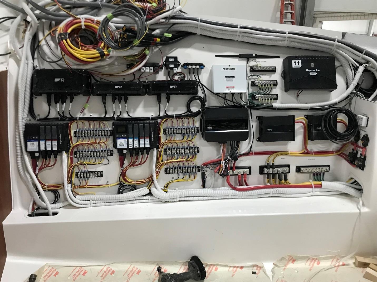
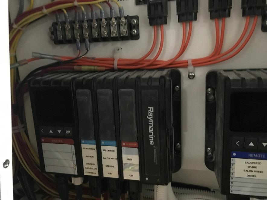
RAYMARINE RNS8
RAYMARINE RNS5
DOMETIC RELAY CONTROL BOX RAYMARINE VCM100
STEROE ANTENNA
YAMAHA GATEWAY SEE FIG 1
LOCATION: AFT CABIN STBD SIDE
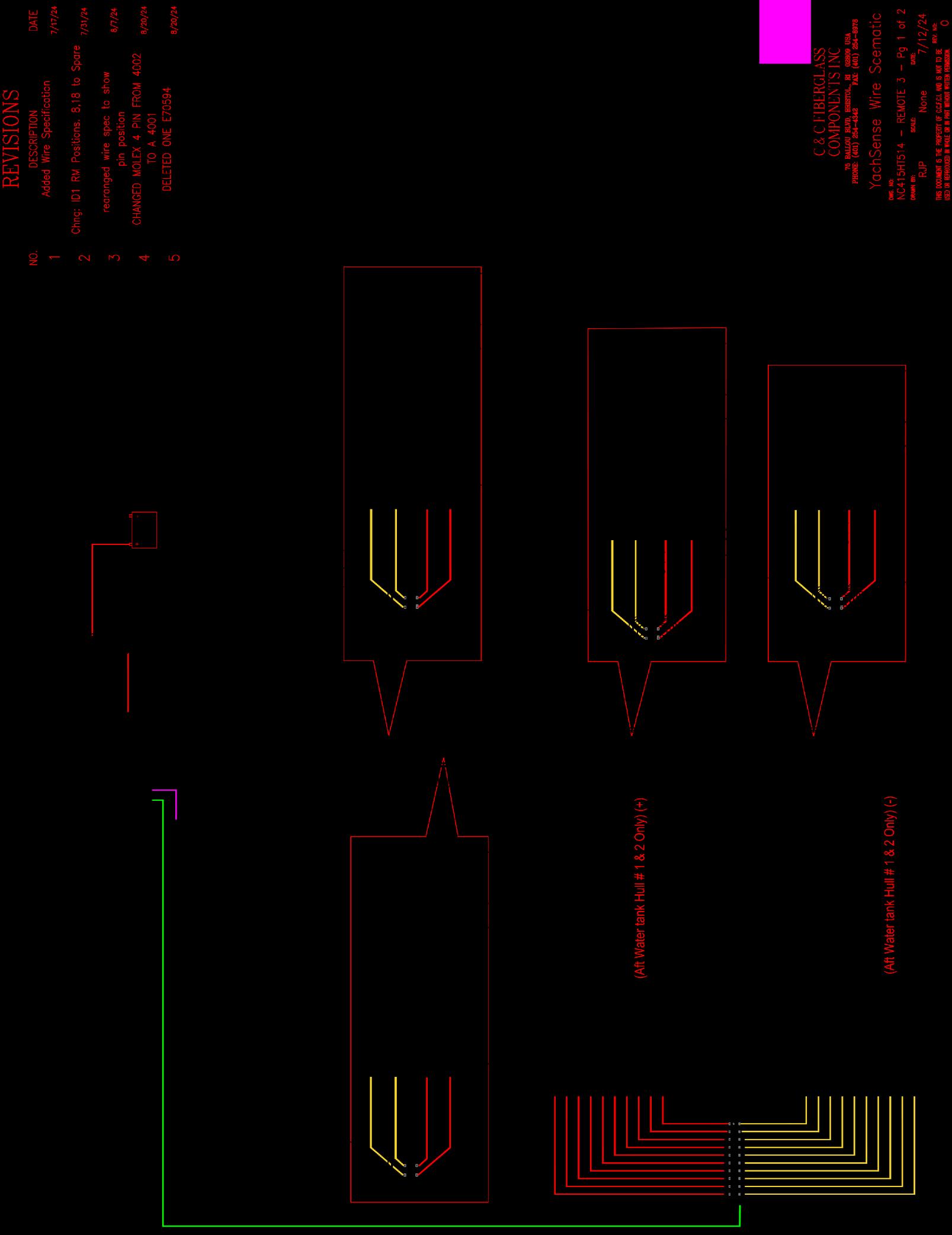
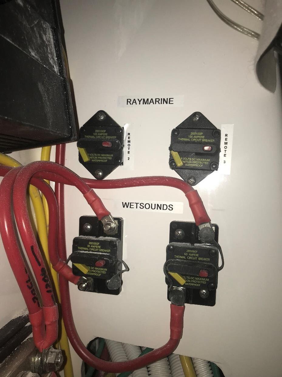
REMOTE 3 CABIN HARNESS ID3
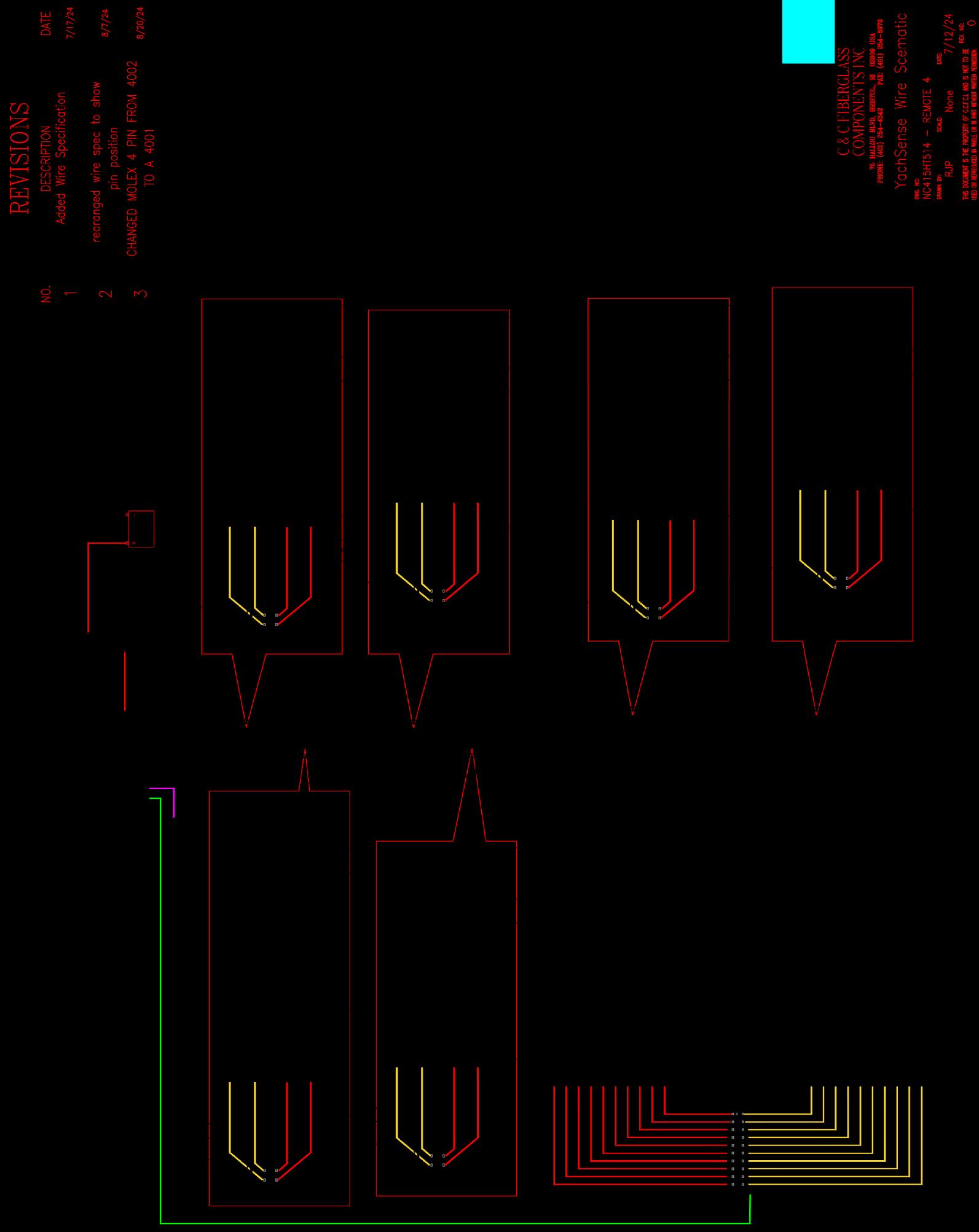
REMOTE 2 MECH RM HARNESS ID2
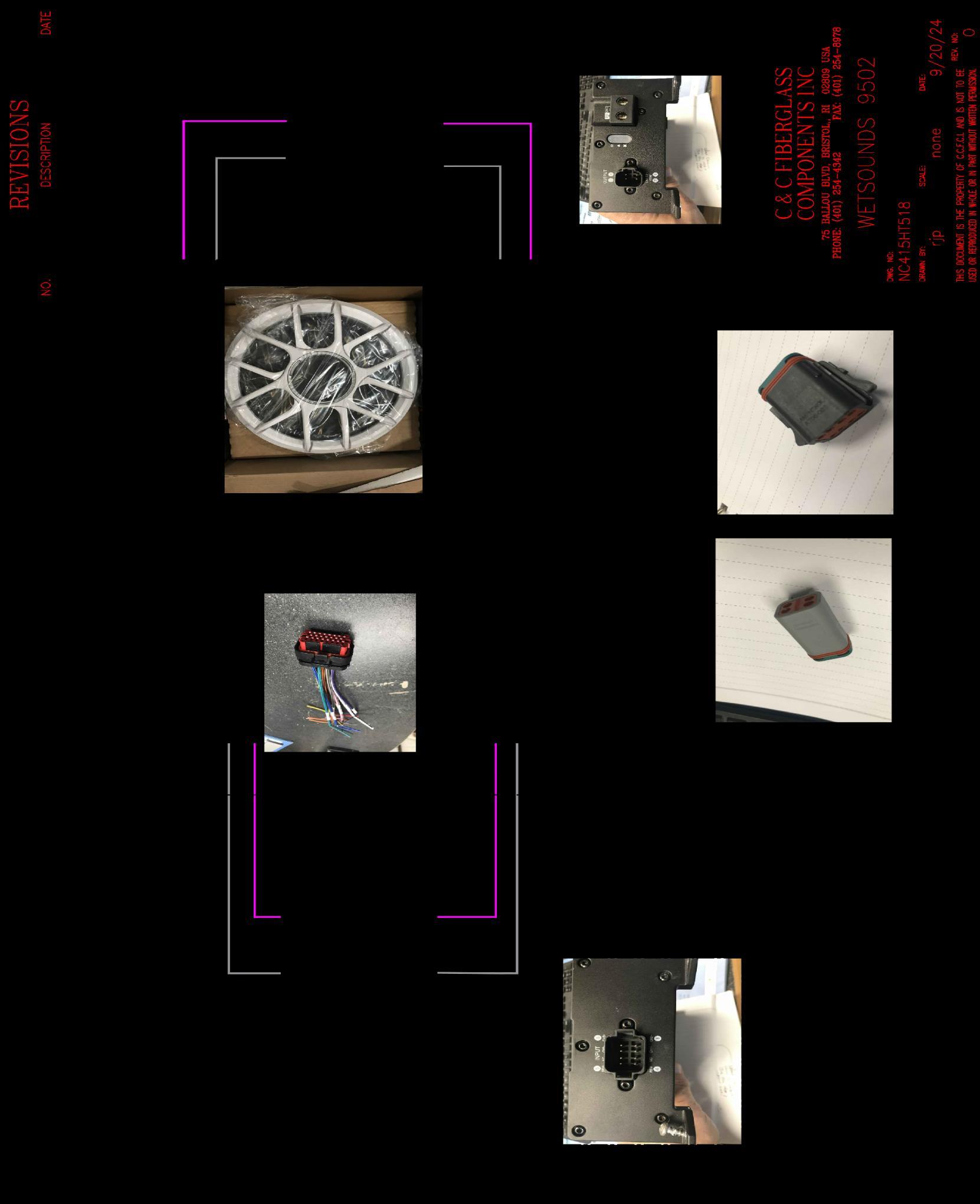
WETSOUNDS 9502
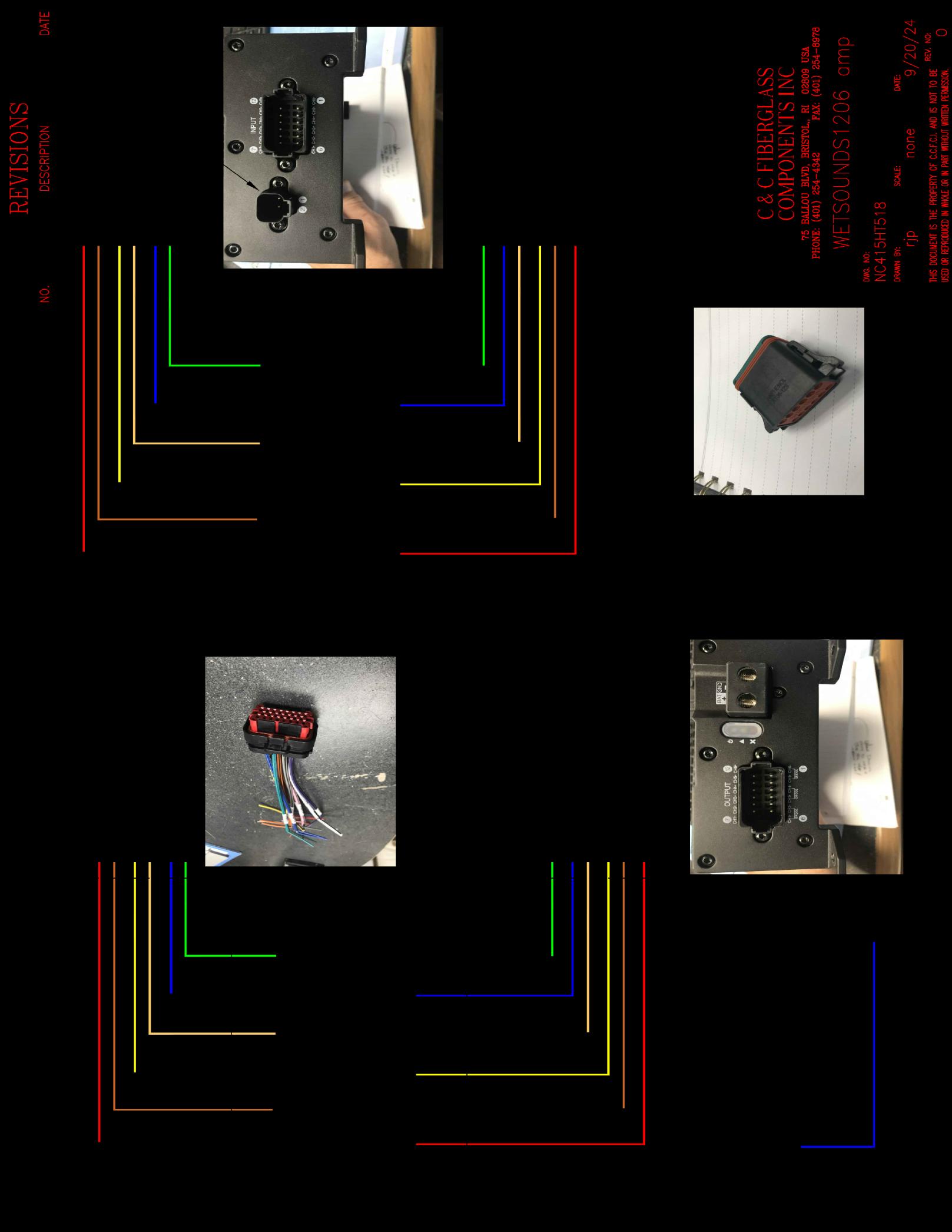
WETSOUNDS 1206
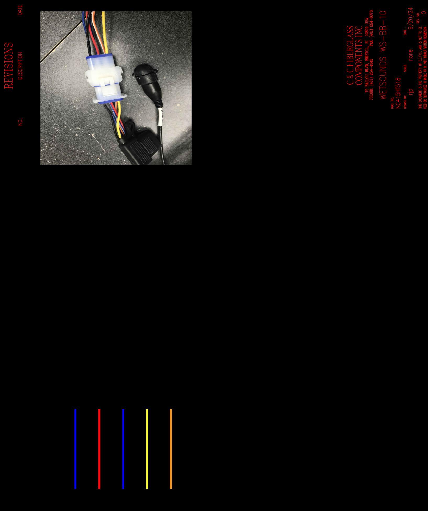
WETSOUNDS
WS-BB-10
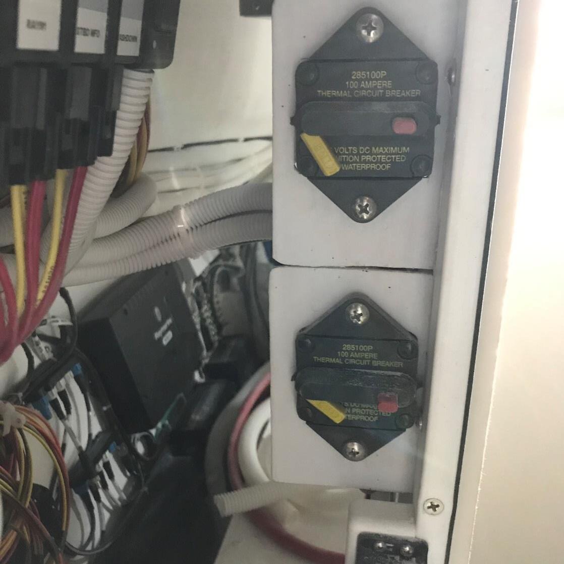
REMOTE 2 BREAKER
100amp
REMOTE 3 BREAKER
100amp
WETSOUNDS 50AMP BREAKER FOR AMP 2 - 9502
WETSOUNDS 80AMP BREAKER AMP 1 - 1206
LOCATION: AFT CABIN STBD SIDE
LOCATION: HELM
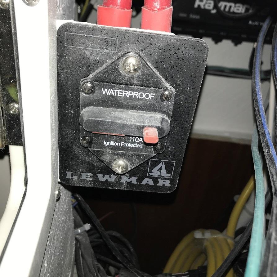
LEWMAR WINDLASS 100 AMP BREAKER BREAKER LOCATED ON HINGE SIDE OF AC ELECTRICAL PANEL.
MASTER MAIN SALON HARNESS ID0
LOCATED BEHIND AC PANEL DOOR AT HELM
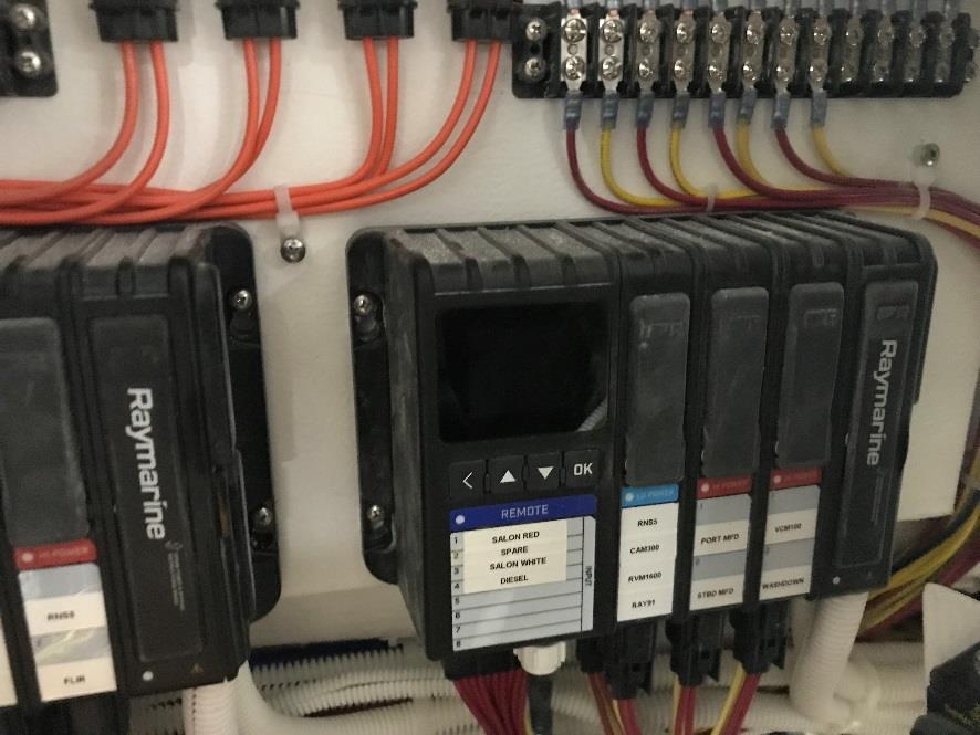
REMOTE 1 MASTER MAIN SALON HARNESS ID0
LOCATED BEHIND AC PANEL DOOR AT HELM
LOCATION: HELM
MASTER MAIN SALON HARNESS ID0
100 AMP
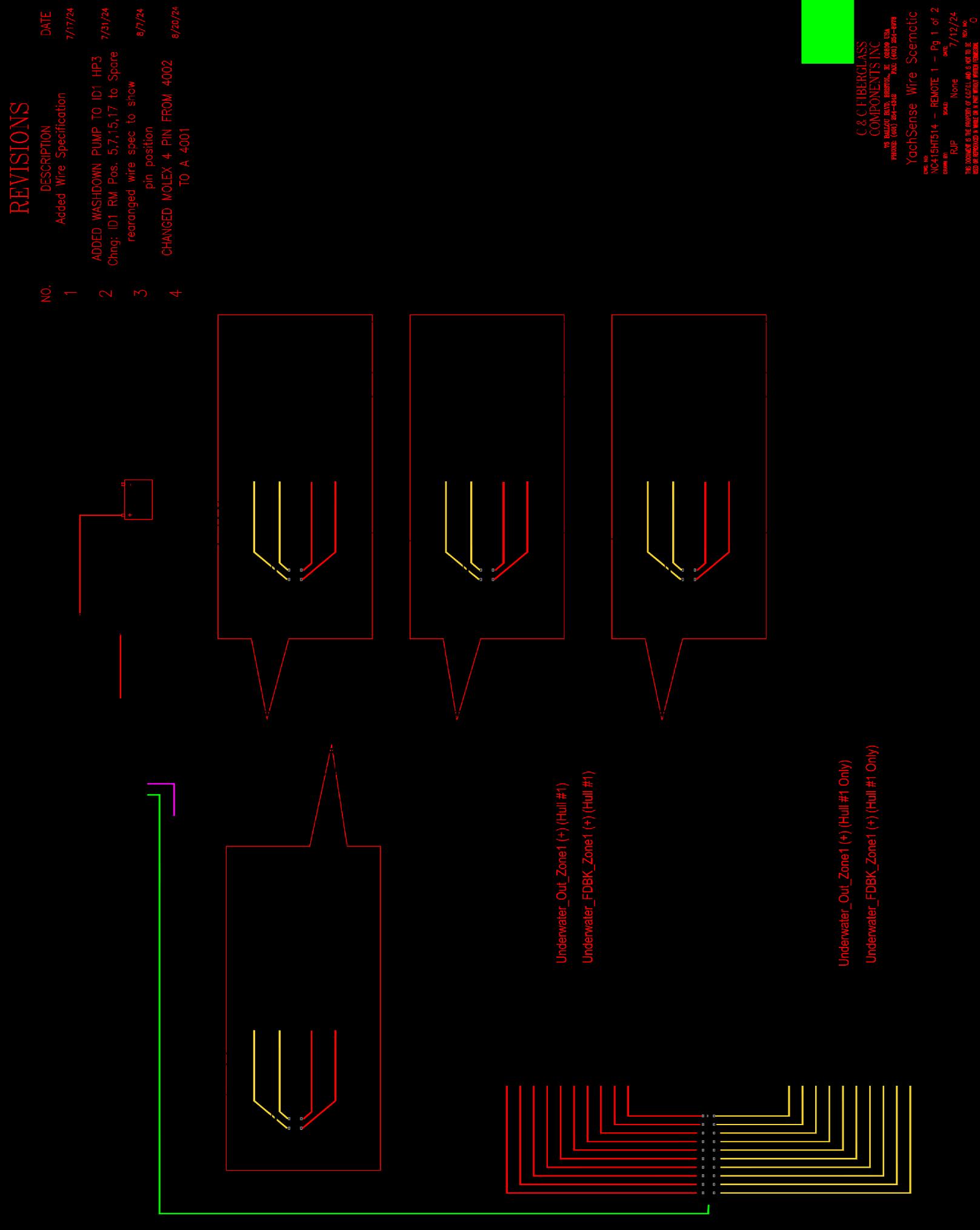
REMOTE 1 MAIN SALON HARNESS ID1
100 AMP
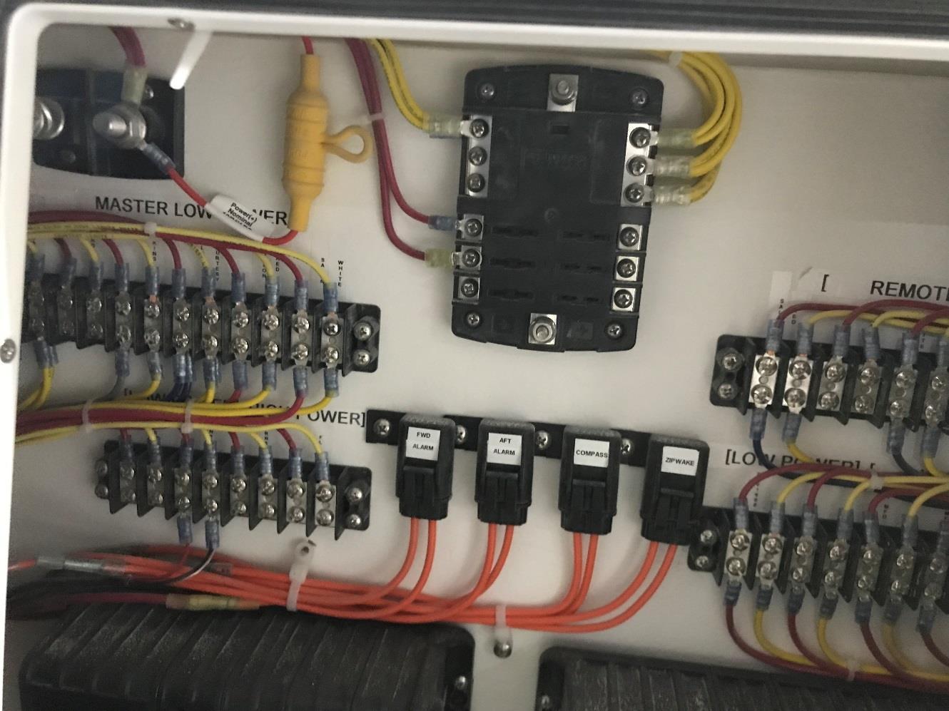
YACHT SENSE 24hr 8-amp
Fuse
24hr HOT +
House +
HOUSE BATT SW FUSE BLOCK
HORN – 10 amp
WIPER – 15 amp
N2K – 15 amp
LOCATION: HELM
MASTER MAIN SALON HARNESS ID0
FWD BILGE ALARM FUSE 24 HR 15 AMP
FWD BILGE ALARM FUSE 24 HR 15 AMP
COMPASS FUSE 2AMP
ZIPWAKE HR 10 AMP
REMOTE 1 MAIN SALON HARNESS ID1
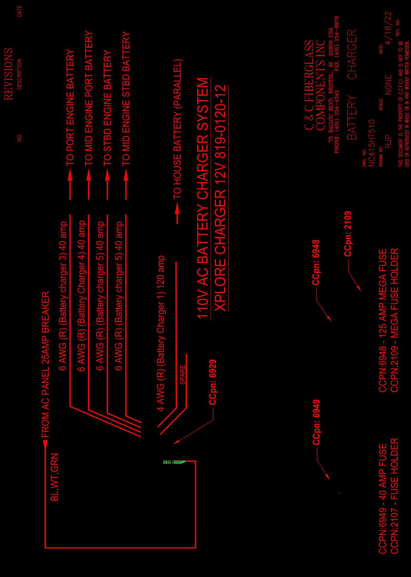
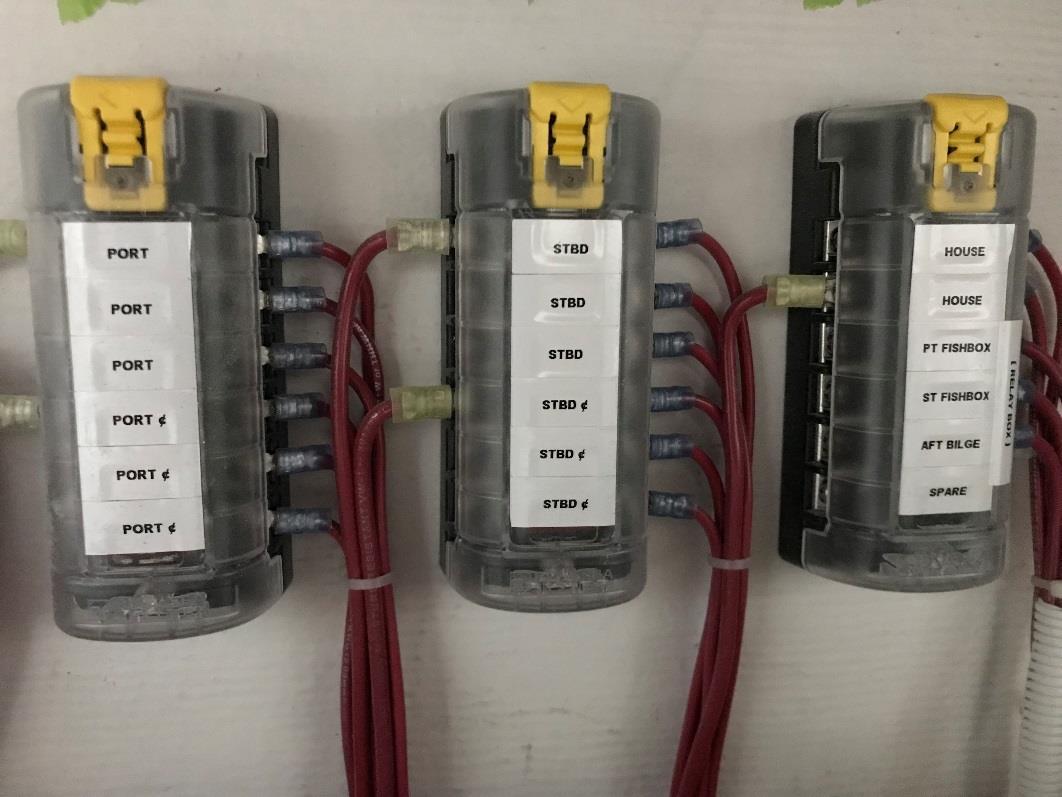
XANTREX BATTERY CHARGER
HOUSE FUSE 120A FUSE
PORT ENGINE 40A FUSE
MID ENGINE PORT ENGINE 40A FUSE
MID ENGINE STBD ENGINE 40A FUSE
STBD ENGINE 40A FUSE
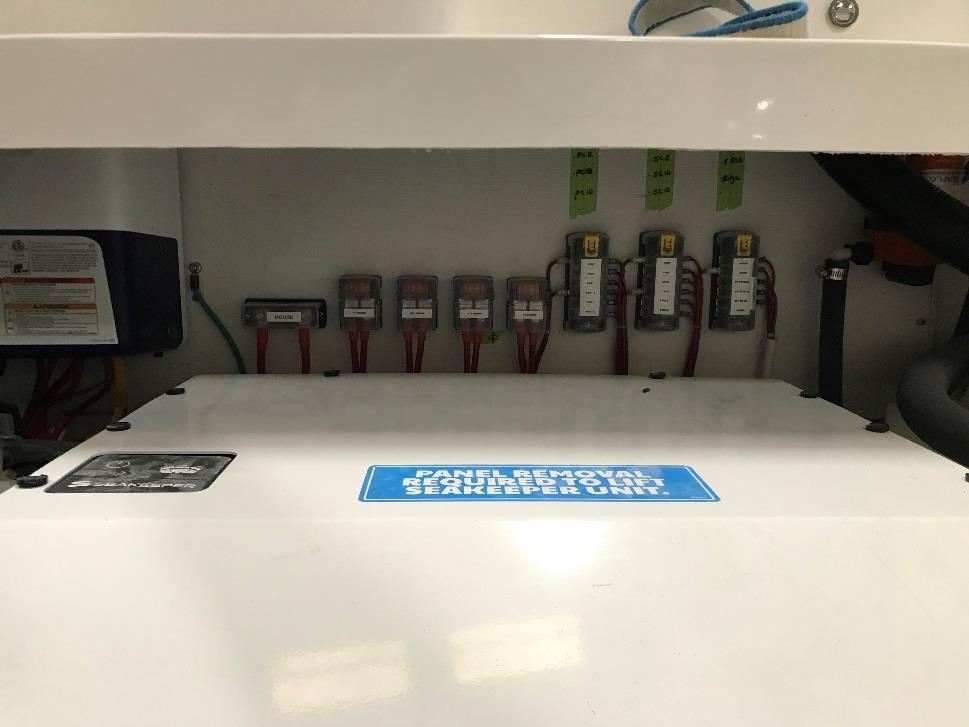
REMOTE RBS & ACR SWITCH FUSES
Xantrex Xplore 120 BATTERY CHARGER FUSES
LOCATION:MECHANICAL ROOM BEHIND SEAKEEPER
RBS & ACR FUSE PANEL
PORT ENGINE RBS 2A
PORT ENGINE RBS 10A
PORT ENGINE ACR 10A
PORT ENGINE CENTER RBS 2A
PORT ENGINE CENTER RBS 10A
PORT ENGINE CENTER RBS 10A
RELAY FUSE PANELS
House RBS 2
House RBS 10
RBS & ACR FUSE PANEL
STBD ENGINE RBS 2A
STBD ENGINE RBS 10A
STBD ENGINE ACR 10A
STBD ENGINE CENTER RBS 2A
STBD ENGINE CENTER RBS 10A
STBD ENGINE CENTER RBS 10A
PT Fish box 15A
STBD Fish box 15A
Aft bilge pump 15A
LOCATION:MECHANICAL ROOM BEHIND SEAKEEPER
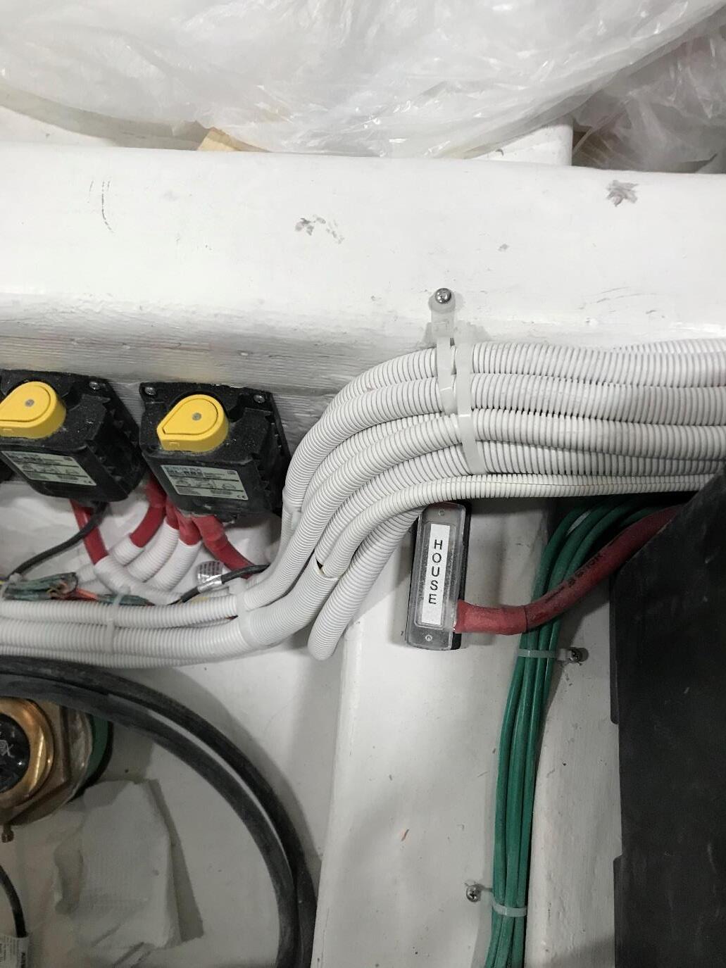
FIG. 3
HOUSE FUSE LOCATED BY THE HOUSE BATTERY IN MECHANICAL ROOM 150 AMP MEGA FUSE
LOCATION:MECHANICAL BETWEEN RBS & HOUSE BATTERY
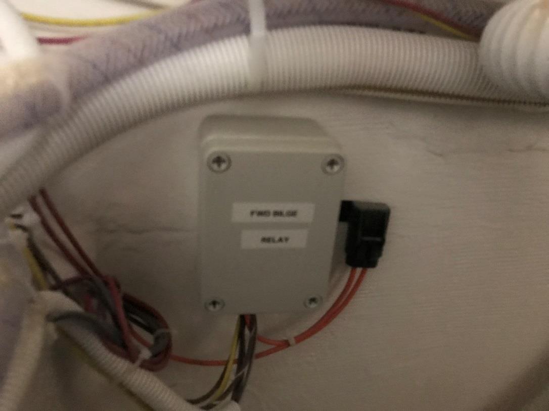
FWD BILGE PUMP RELAY BOX
LOCATED UNDER AFT DOUBLE BUNK HATCH AGAINST TRANSVERSE
FWD BILGE PUMP 24HR FUSE 15 AMP
LOCATION:MECHANICAL AFT CABIN TWIN BUNK HATCH
BOW THRUSTER RBS
BOWTHRUSTER ACR
BOW THRUSTER BATTERY
5A RBS FUSE
RBS 10amp fuse 1ea
ACR 10amp fuse 1ea
BOW THRUSTER BATTERY
250 AMP FUSE
LOCATION: UNDER AFT DOUBLE BUNK HATCH
U.S. Dept. of Homeland Security OMB No: 1625-0003
U.S. Coast Guard CG-3865 (Rev. 07-08)
Recreational Boating Accident Report
Expires: 7/31/2011
NOTE: each boat operator/owner involved in an accident should submit a separate report. Estimated report form completion time:30 min For each question below, please provide answers IF APPLICABLE AND IF KNOWN, otherwise leave blank.
REPORT SUBMISSION
Report required because (select all that apply):To be submitted within:
At least one person in this accident died : 48 hours (if injury, disappearance or death) If so, how many?10 days (if boat/property damage only )
At least one injured person in this accident required or was in need of treatment beyond first aid: If so, how many?
At least one person in this accident disappeared and has not
To be submitted to: yet been recovered:If so, how many?(Local State Reporting Authority)
All boat and other property damage (e.g., fishing/hunting gear) caused by this accident totaled (or likely totaled) $2,000 or more:
Approximate value of damage to your boat: $Phone: ( )
Approximate value of damage to your other property: $
Your or another boat in this accident was (or likely was) a total loss
Report submitted by (select all that apply):
Boat Operator (required if possible)
Boat Owner (if operator unable, or same as operator)
Other (describe) :
First name:Last name:
Phone:--
ACCIDENT SUMMARY
You may submit any comments concering the the accuracy of the burden estimate or any suggestions for reducing the burden to: Commandant (CG-5422), U.S. Coast Guard, Washington, DC 20593-0001 or Office of Management and Budget, Paperwork Reduction Project (1625-0003), Washington, DC 20503.
For State Agency Use Only
First name:
Last name: Phone:
Primary cause of accident:
WHENACCIDENT DESCRIPTION
Date: mm/dd/yy
Time: : am pm (select one)
WHERE
Body of water name:
Location (on water)
description:
Nearest city/town:
County:
State:
Briefly describe this accident (attach extra pages if necessary):
DAMAGE TO YOUR BOAT
Briefly summarize any damage to your boat:
YOUR BOAT - PEOPLEDAMAGE TO YOUR OTHER PROPERTY (NOT BOAT)
# people on board (including operator):
# people being towed (e.g., on tubes, skis):
# people wearing lifejackets (on board or towed) :
OTHER BOATS INVOLVED IN ACCIDENT
# of other boats involved?
Briefly summarize any damage to your other property (not boat):
For each question below, please provide answers IF APPLICABLE AND IF KNOWN, otherwise leave blank.
YOUR BOAT
BOAT IDENTIFICATION
Your boat name:Manufacturer:
Model name:Model year:
Registration #:Documentation #:
Hull Identification # (HIN):Rented: Yes No
SIZE ESTIMATES
Length:ft.Depth from transom (stern) to Beam width at widest point:ft. keel (bottommost point):ft.in.
HULL MATERIAL
Type of hull material (select one):
Fiberglass Wood Rubber/vinyl/canvas Other (describe) :
Aluminum Steel Plastic
BOAT TYPE
Boat type (select one): Available propulsion (select all that apply):
Cabin motorboat Inflatable Canoe Personal watercraft (PWC) Propeller Air thrust Open motorboat Houseboat Rowboat (e.g., Wave Runner™ , Sail Other (describe) :
Auxiliary sail Sail (only) Air boat Jet Ski™, Sea-Doo™) Manual Pontoon boat Kayak Other (describe) : Water jet
ENGINE
# engines:Engine type and horsepower (select one): Fuel type (select all that apply):
Manufacturer: Outboard Sterndrive (I/O) Inboard None Gasoline Electric Total horsepower:hp Diesel
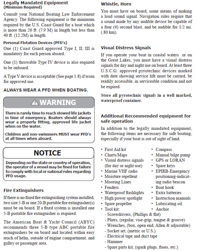
SAFETY MEASURES
Organizations that have conducted a vessel safety check (VSC) on board your boat within the past year (including carriage of safety equipment, e.g., lifejackets, anchor and line, fire extinguishers): Federal Agency (Name):
US Coast Guard Auxiliary:VSC Decal? Yes No
US Power Squadrons:VSC Decal? Yes No
State Agency (Name):
Other Agency (Name):
# Life jackets on board:# Fire extinguishers on board: Type of fire extinguishers (e.g., ABC): # Fire extinguishers used:Amount of fire extinguisher used:
ACCIDENT DETAILS - EXTERNAL CONDITIONS
WEATHER
Overall weather was (select one):It wasVisibility wasWind was (select one):
Operator inexperience Heavy weather Missing/inadequate
Excessive speed Language barrier Hull failureaids to navigation (e.g., buoy,
Improper anchoring Navigation rules violation Ignition of fuel or vapor daymarker)
Improper loading Failure to vent Starting in gear Inadequate on-board
Overloading Dam/lock Sharp turnnavigation lights
Improper lookout Force of wake/wave
People on gunwale, bow
Other (describe): or transom
ACCIDENT DETAILS - YOUR BOAT
MACHINERY/EQUIPMENT FAILURE
Failure of the following machinery/equipment on your boat contributed to this accident (select all that apply):
Engine Sail/mast Steering Radio Fire extinguisher
Electrical system Onboard lights Throttle Auxiliary equipment Ventilation
Fuel system Seats Shift
Onboard navigation aids (e.g., GPS, Loran)
Other (list):
ACCIDENT DETAILS - EVENTS ON YOUR BOAT
ACCIDENT EVENTS
Sound equipment (e.g., horn, whistle)
Types of events occurring to/on your boat during accident (select all that apply):
Collision with recreational boat
Collision with commercial boat (e.g., tug, barge)
Collision with fixed object (e.g., dock, bridge)
Collision with submerged object (e.g., stump, cable)
Flooding/swamping
Fire/explosion - fuel
Person fell overboard
Person fell on/within boat
Fire/explosion - non-fuel Sudden medical condition
Carbon monoxide exposure
Person struck by boat
Collision with floating object (e.g., log, buoy) Mishap of skier, tuber, Person struck by
Capsizingwakeboarder, etc.propeller or propulsion unit
Grounding
Person left boat voluntarily Person electrocuted
Sinking Person ejected from boat (caused by collision or manuever)
Other (describe) :
For each question below, please provide answers IF APPLICABLE AND IF KNOWN, otherwise leave blank.
ACCIDENT DETAILS - YOUR BOATINJURED PEOPLE RECEIVING OR IN NEED OF TREATMENT BEYOND FIRST AID
Report only injured people on, struck by, or being towed by your boat , receiving or in need of treatment beyond first aid
Do not report injured people on, struck by, or being towed by another boat or no boat (e.g., swimmers, people on a dock). If more than one injured person to report, attach additional copies of this page. If none , SKIP INJURED PEOPLE section.
INJURED PERSON
First:MI:Last:
Street: City:State:Zip:Phone:--Age:
INJURY DETAILS
Injury caused when person (select all that apply):Nature of most serious injury (select one):
Struck the:
Was struck by a:
(e.g., boat, water)
(e.g., boat, propeller)
Was exposed to carbon monoxide poisoning
Received an electric shock
Other (describe) :
Person was wearing lifejacket?
Scrape/bruise Dislocation
Cut Internal organ injury
Sprain/strain Amputation
Concussion/brain injury Burn
Spinal cord injury Other (describe) : Broken/fractured bone
Yes NoBody part of most serious injury (e.g., head, hip, knee) : Person received treatment beyond first aid? Yes No
Person was admitted to a hospital? Yes No
ACCIDENT DETAILS - YOUR BOAT - DEATHS/DISAPPEARANCES
Only report deaths/disappearances of people on, struck by, or being towed by your boat. If more than one death/disappearance to report, attach additional copies of this page. If none , SKIP DEATHS/DISAPPEARANCES section.
Injury caused when person (select all that apply):Nature of death/disappearance (select one):
Struck the:
Was struck by a:
(e.g., boat, water)
(e.g., boat, propeller)
Death - by drowning
Death - other likely cause (describe) : Was exposed to carbon monoxide poisoning
Received an electric shock
Other (describe) :
Disappeared and not yet recovered
Person was wearing lifejacket? Yes No
For each question below, please provide answers IF APPLICABLE AND IF KNOWN, otherwise leave blank.
ACCIDENT DETAILS - YOUR BOAT OPERATOR
OPERATOR INSTRUCTIONOPERATOR SAFETY MEASURES
Boating safety instruction completed (select all that apply):On board, prior to accident, was operator wearing: NoneA lifejacket?
State course Yes No
USCG Auxiliary courseAn engine cut-off switch (Lanyard or wireless device) US Power Squadrons courseif equipped?
Internet (name of sponsoring organization): Yes No
On board, prior to accident, was operator using: Other (describe) :Alcohol?
Yes No
Drugs?
OPERATOR EXPERIENCE
Yes No
Operator arrested for Boating Under the Influence?
Experience operating this type of boat (select one): Yes No 0 to 10 hours Over 100, up to 500 hours
Weather reports consulted prior to accident? Over 10, up to 100 hours Over 500 hours Yes No
ACCIDENT DETAILS - OTHER KEY PEOPLE
Only report other key people not already documented as injured, died, disappeared or operator/owner of your boat. If more than two other key people to report, attach additional copies of this page.
NAME/ADDRESS
This other key person was a(n) (select all that apply):
Other boat operator Other boat owner Owner of other damaged property Passenger on your boat Witness
Other boat name (if any):Phone:--
Other boat registration # (if any):
NAME/ADDRESS
This other key person was a(n) (select all that apply): Other boat operator Other boat owner Owner of other damaged property Passenger on your boat Witness
Other boat name (if any):Phone:--
Other boat registration # (if any):
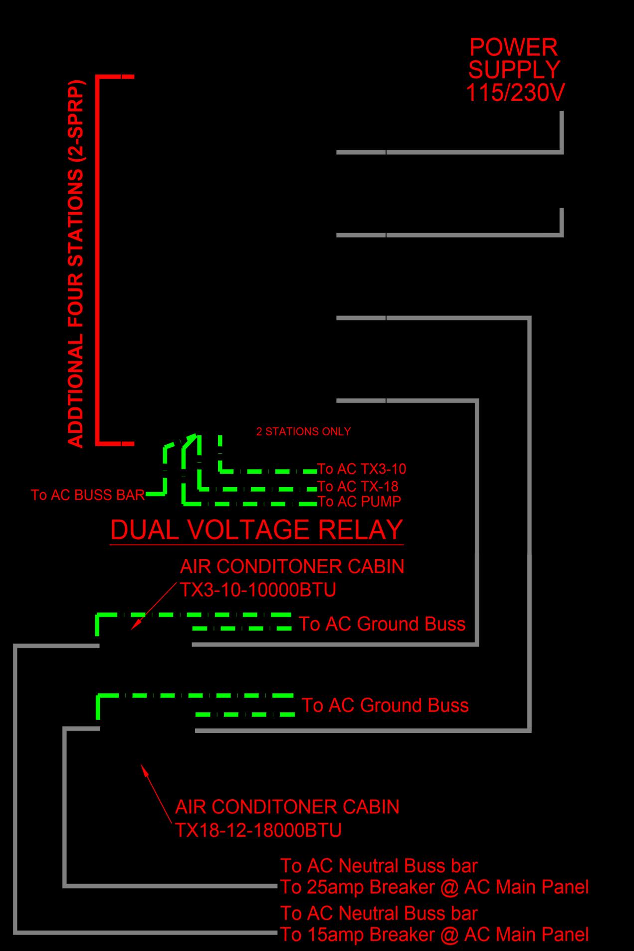
Reverse - Cycle Air Conditioning.
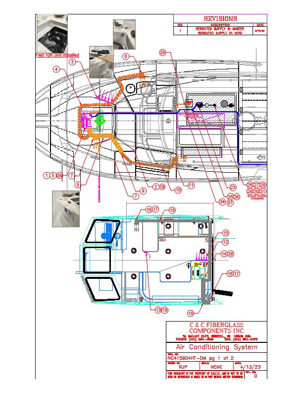
The reverse-cycle air condition system consists of an air handler, seawater pump with seacock and strainer and a control unit so the water will be activated by demand when the AC unit comes on. One control unit can handle up to six units. The unit is located in the aft cabin Starboard Electronics locker.
The air conditioning/heating system is controlled by two touch display units. One is located on the port side cabinet in the main common area and the other located by Main Salon. The displays allow the operator to preset the temperature for the cabin and wheelhouse. The air unit will activate automatically when the temperature of the cabin is not consistent with the preset temperature. When the air handler is activated, seawater is pumped into the system by way of a seacock and strainer, passes through the compressor cooling the condensing coils, and then flows overboard through the thru-hull drain. Condensation created by the A/C units will drain into the shower sump pump.
STARTING THE SYSTEM
• Make sure the seacock is OPEN.
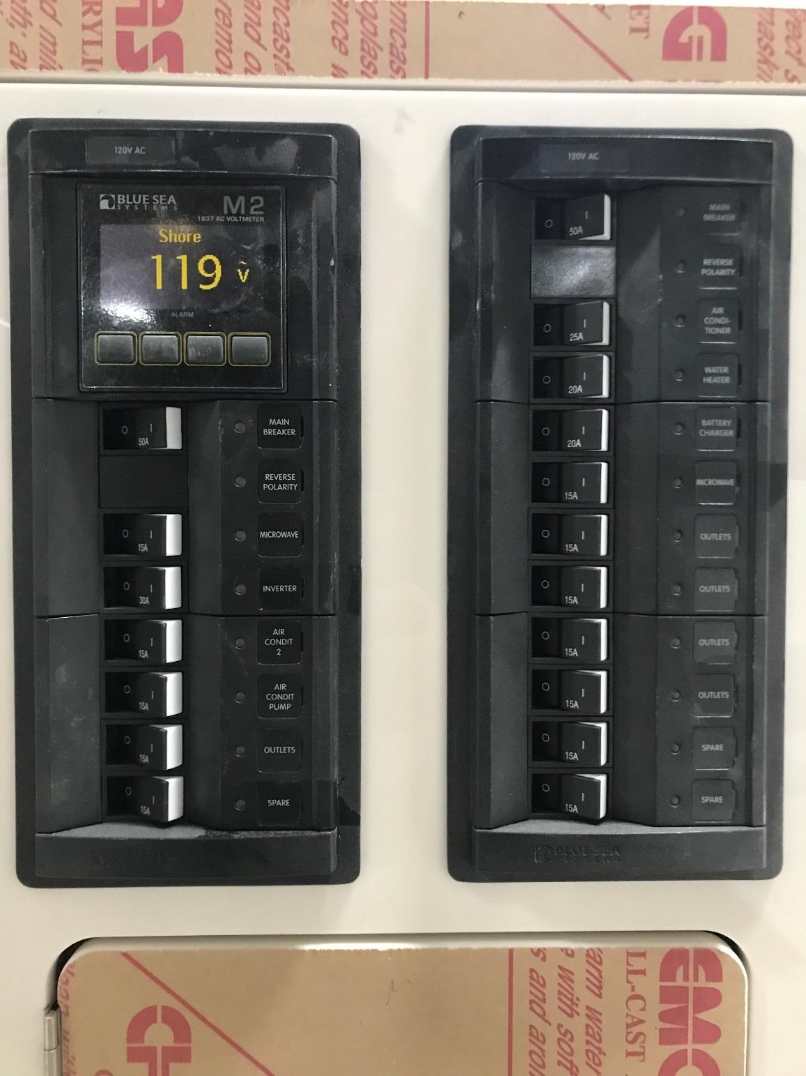
• Turn ON the “A/C PUMP” breaker Located on your AC panel. See Fig 2
Turn ON the “Shower Sump Pump” breaker Located on your MFD. See Fig 1Fig. 1 MFD Screen
• Turn on desired A/C Unit Breaker (“Air Con” Breaker on right panel controls wheelhouse, “Air Con 2” on the left panel controls cabin. Located on your AC panel
Air Condition 1
[Cite your source here.]
Air Condition 2
[Cite your source here.]
Air Condition Pump
[Cite your source here.]
Fig 2. AC PanelNC415HT
REVERSE
• Set the display to the desired temperature. The Main Salon display is located at port side setee by the enclosure door. The Master is located at the companionway seat.
Maintenance
The air conditioning unit requires very simple maintenance. Periodically check and clean the raw water intake on the exterior of the hull, the water strainer at the pump and the air filter. Access to the wheelhouse A/C Unit is under the port side settee cushion. Access to the cabin unit is under the v-berth storage locker.
NOTICE
REFERTOTHEMANUFACTURER’SMANUALIN YOUROWNER’SMANUALPACKETFORCOMPLETE INSTRUCTIONS AND WARRANTY.NOTICE
MAIN SALON A/C NOT INTENDED TO COOL MAIN SALON AREA WITH ENCLOSURE DOOR AND WINDOWS OPEN
REVERSE
REVERSE
Fault On Panel
If a fault appears on the panel, please contact your local NorthCoast dealer for assistance.
NOTICE
A/C not intended to cool helm deck area with enclosure up
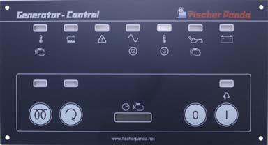
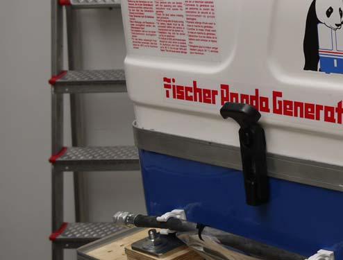
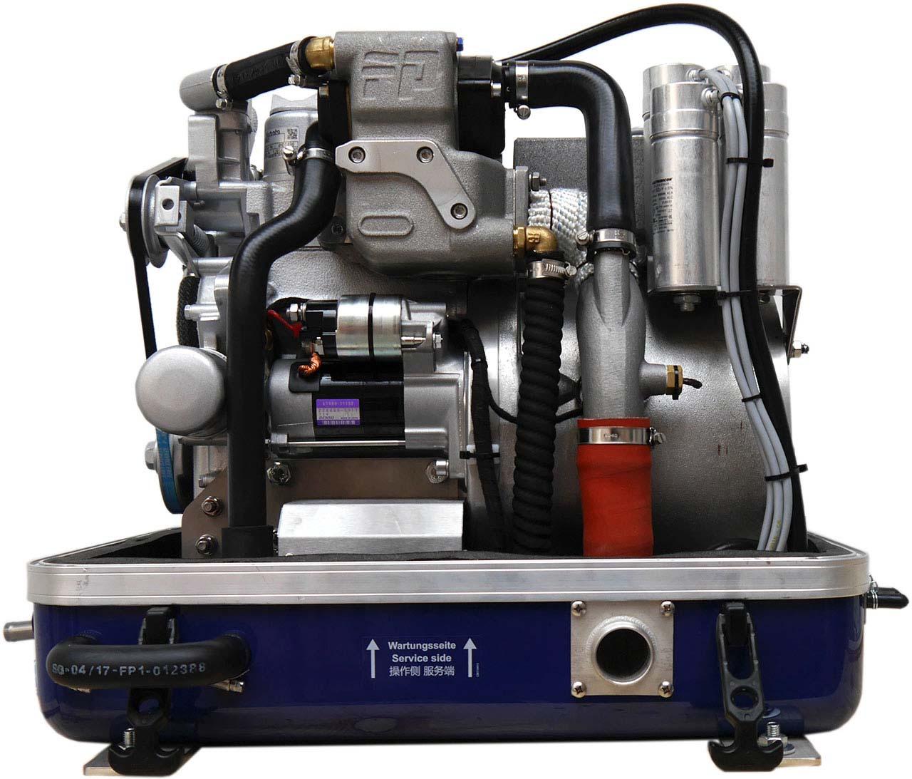
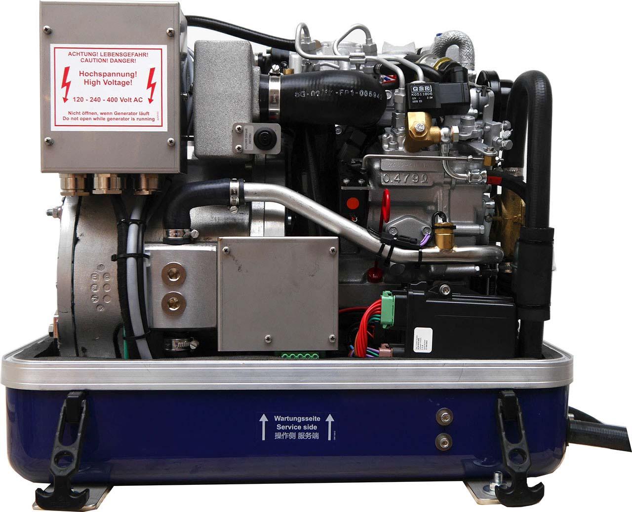
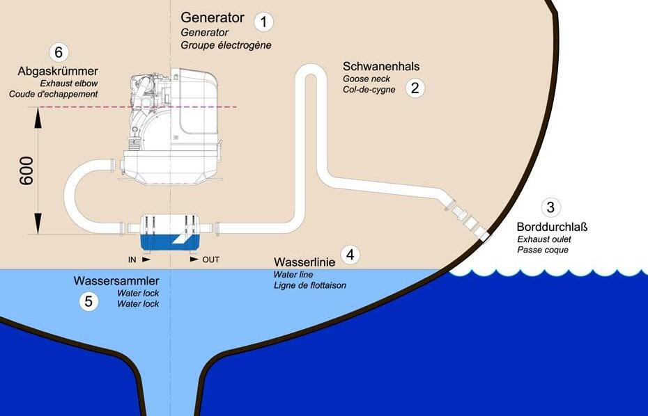
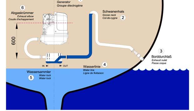
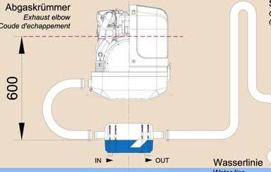
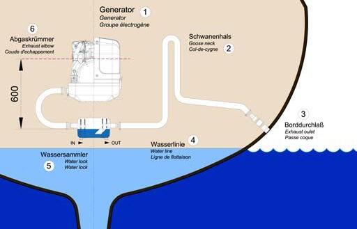
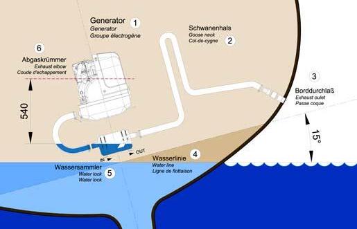
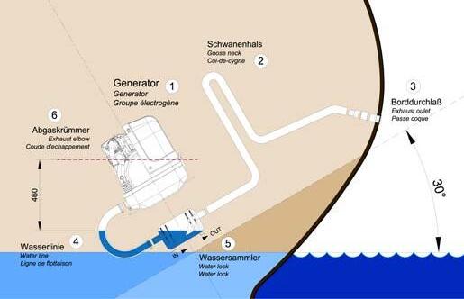
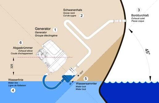
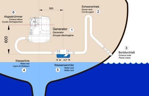
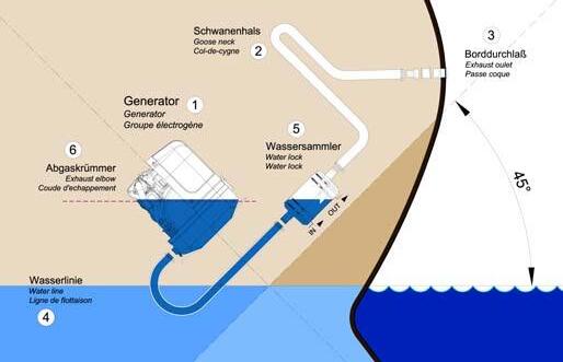
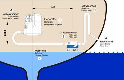
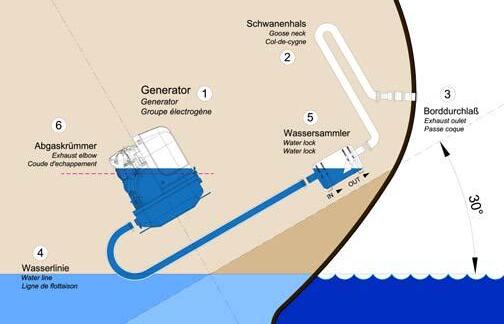
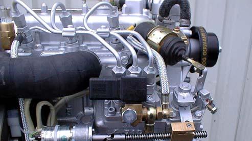
GENERATOR
GENERATOR
It is recommended that you read and understand the information in the manufacturers owner’s manual before operating the generator.
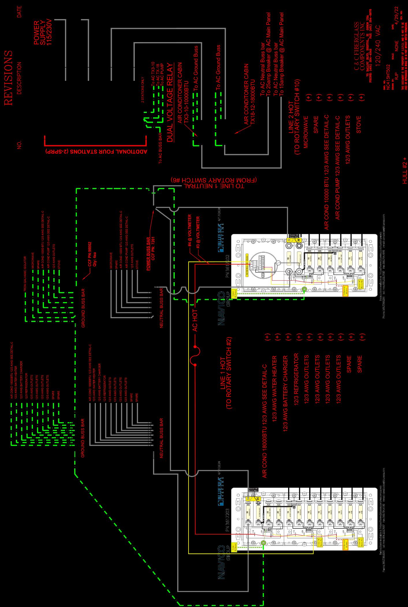
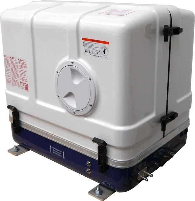
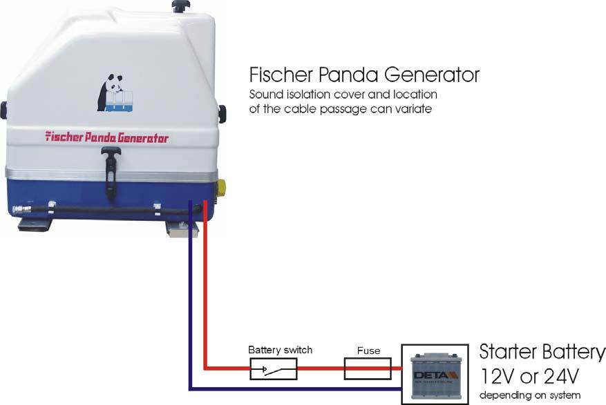
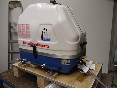
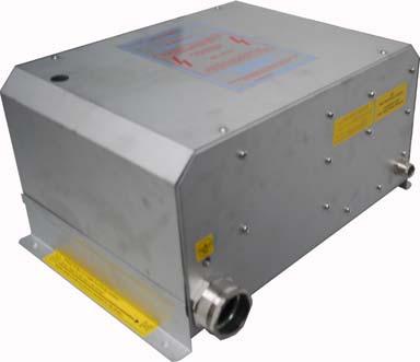
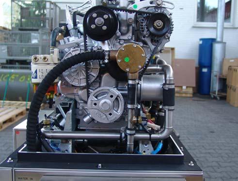
Your boat’s AC electrical system operates on a Panda 9KW 120V/220v from the generator and/ or shore power. The generator is runs on a Kubota diesel engine that has its own fuel tank NET 32.4 gallons. The generator is enclosed with its own sound enclosure which reduces the sound decibels. The generator connections to the AC electrical system through cables connected to the rotary switch on the AC distribution panel. The generator has a built-in cooling pump which draws cooling water through a seacock located in the aft machinery compartment. This water passes through a strainer before entering the engine cooling manifold. The generator draws fuel from its own diesel fuel tank.
WARNING
CARBON MONOXIDE can cause severe NAUSEA, FAINTING or DEATH. The exhaust system must be leak proof and routinely inspected.
EXPLOSIVE FUEL VAPORS Can cause SEVERE INJURY or DEATH. Use extreme care when handling, storing and using fuels.
MOVING PARTS Can cause SEVERE INJURY or DEATH. Operate the generator set only when all guards, screens and covers are in place. FIRE Can cause SEVERE INJURY or DEATH. Do not smoke or permit flames or sparks near fuels or the fuel system.
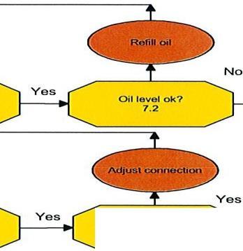
Startup instructions
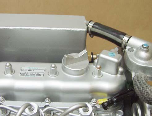
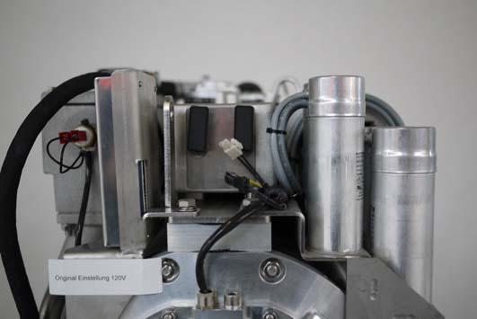
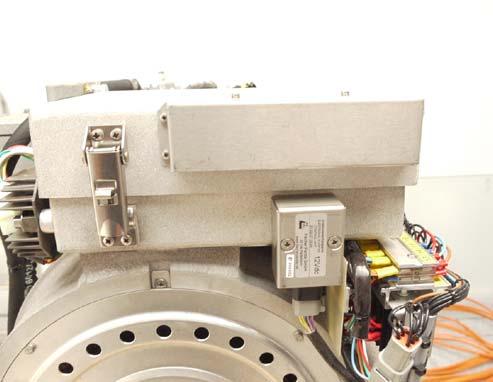
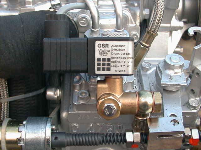
1. Oil Level Control (ideal level: MAX). True, the diesel motor automatically switches off when ATTENTION! OIL PRESSURE CONTROL! there is a lack of oil, but it is very damaging for the motor, if the oil level drops to the lowest limit. Air can be sucked in suddenly when the boat rocks in heavy seas, if the oil level is at a minimum. This affects the grease in the bearings. It is therefore necessary to check the oil level daily before initially running the generator. The oil level must be topped up to the maximum level, if the level drops below the mark between maximum and minimum levels.
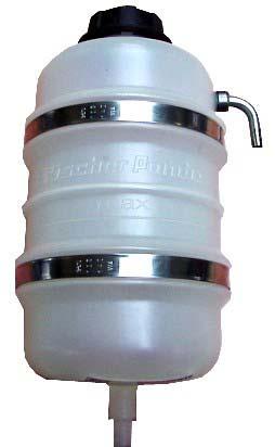
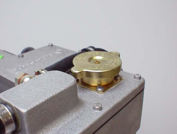
2. State of Cooling Water. The Panda Generator See/Page 46, Chapter 5: The Panda Generator 28.7.17 The external compensation tank should be filled up to a maximum of in a cold state. It is very important that large expansion area remains above the cooling water level.
3. Switch the Rotary Land Electricity/Generator Switch to OFF.
4. Turn Battery Switch to the ON Position See Fig 2 Labeled Engine 1.
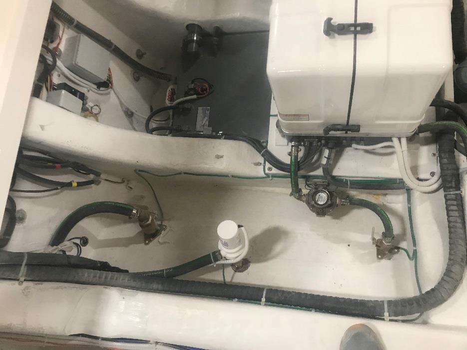
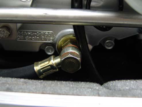
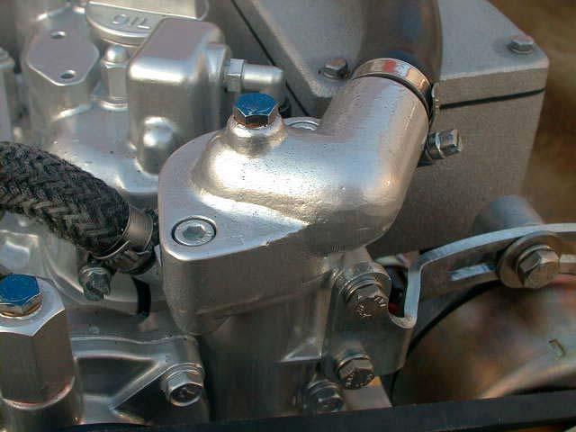
5. Open Sea Cock See Fig 1 for Cooling Water Intake. For safety reasons, the seacock must be closed after the generator has been switched off. It should be re-opened before starting the generator.
6. Turn Generator on from Fischer Panda Start Panel See Fig 3
7. You now have AC power to both your AC panels.
8. Check Exhaust discharge make sure water is being discharged
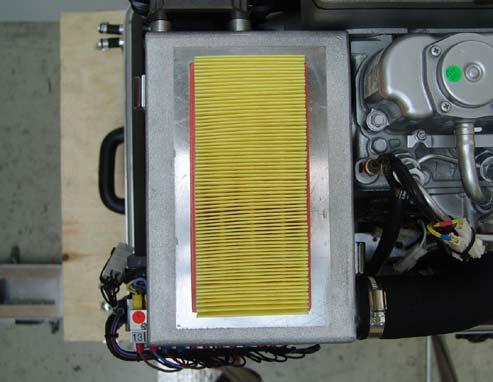
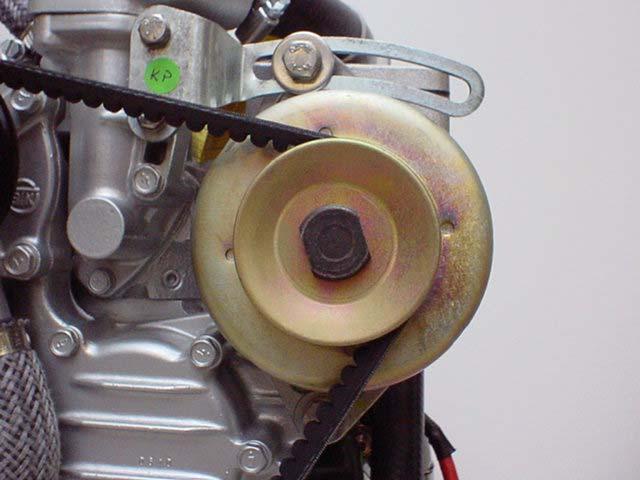
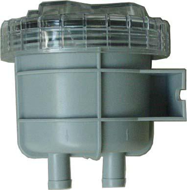
9. Check Raw Water Filter. The raw water filter must be regularly checked and cleaned. The impeller fatigue increases, if residual affects the raw water intake.
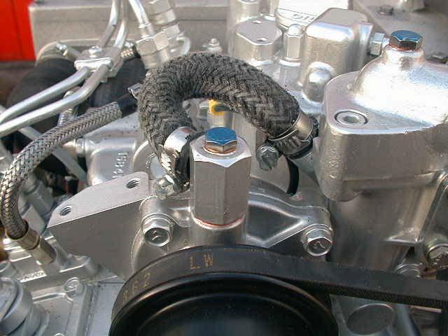
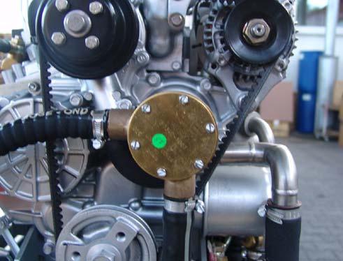
10. Check all Hose Connections and Hose Clamps are Leakage. Leaks at hose connections must be immediately repaired, especially the raw water impeller pump. It is certainly possible that the raw water impeller pump will produce leaks, depending upon the situation. (This can be caused by sand particles in the raw water etc.) In this case, immediately exchange the pump, because the dripping water will be sprayed by the belt pulley into the sound insulated casing and can quickly cause corrosion.
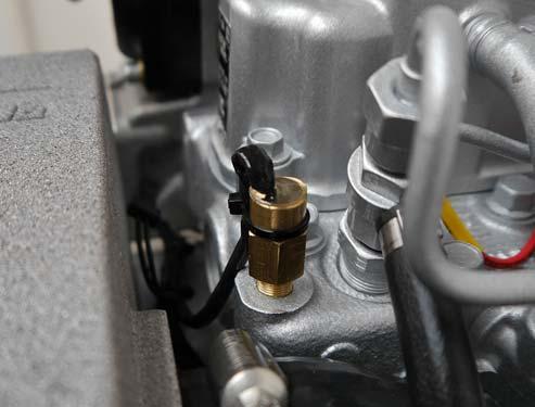
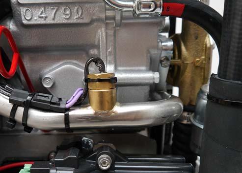
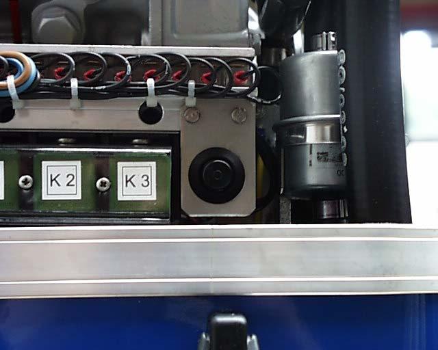
11. Check all electrical Lead Terminal Contacts are Firm. This is especially the case with the temperature switch contacts, which automatically switch off the generator in case of faults. There is only safety if these systems are regularly checked, and these systems will protect the generator, when there is a fault.
12. Check the Motor and Generator Mounting Screws are Tight. The mounting screws must be checked regularly to ensure the generator is safe. A visual check of these screws must be made, when the oil level is checked.
13. Check the Automatic Controls Functions and Oil Pressure. Removing a cable end from the monitoring switch carries out this control test. The generator should then automatically switch off. Please adhere to the inspection timetable (see Checklist in the appendix)
Shutdown Instructions:
1. Turn Fischer Panda panel power OFF
2. After generator has been turned OFF now CLOSE the seacock
3. Turn Generator Rotary switch back to OFF position
Generator Seacock
Fig. 1 Seacock Location
Engine 1 / Generator
Battery Switch
Switch to SHOREPWR for Shore power use
Switch to Generator for generator use
Fig 2 Shore Power Rotary Switch
Fig 3 Panda Generator Start Panel Located on the Dash
Duplication and change of the manual is permitted only in consultation with the manufacturer! Fischer Panda GmbH, 33104 Paderborn, reserves all rights regarding text and graphics. Details are given to the best of our knowledge. No liability is accepted for correctness. Technical modifications for improving the product without previous notice may be undertaken without notice. Before installation, it must be ensured that the pictures, diagrams and related material are applicable to the genset supplied. Enquiries must be made in case of doubt.
Inhalt / Contens
Inhalt / Contens
4.5Special
4.5.1Reference
4.5.2Arrangements
4.5.3Arrangements
4.5.3.1Arrangements
4.5.3.2Arrangements
4.5.4.1Arrangements
4.5.4.2Arrangements
6.3.5Operating
Inhalt / Contens
Inhalt / Contens
8.6Oil
8.9Verifying
8.10Checking
Inhalt / Contens
9.6Overloading the generator..
9.6.1Monitoring the Generator Voltage .....................................................................................119
9.6.2Automatic voltage monitoring and auto-shut down
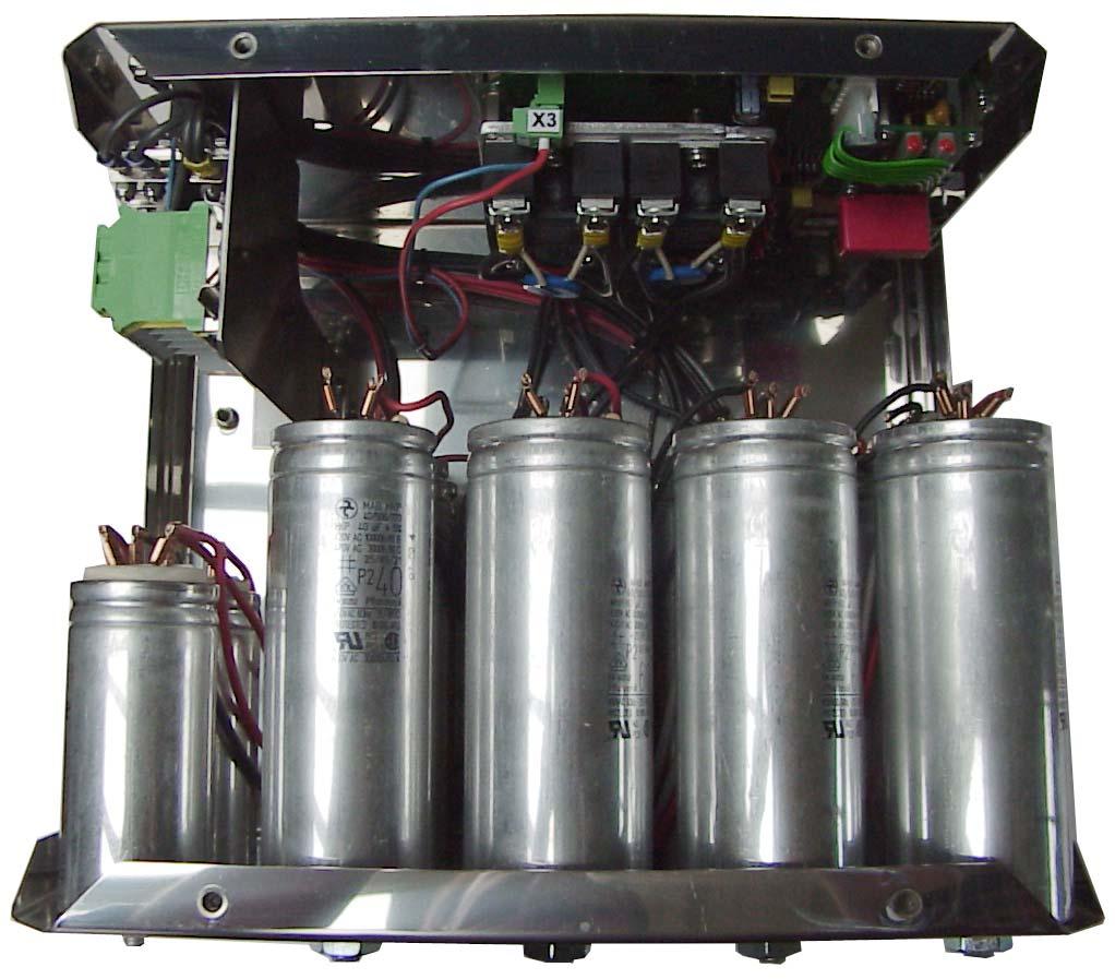
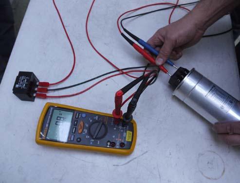
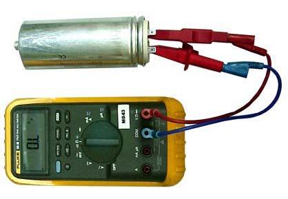
9.6.2.1Checking the electrical connections to the capacitors.......................................
9.6.3Check the
9.6.4Measuring the Ohm Resistance of
9.6.5Check the Windings for Short
9.6.6Measuring the Inductive
9.7.1Rotor Magnetism Loss and „Re-magnetising“
9.8.1
9.8.2Re-start with
9.8.3Lifting
Leere Seite / Intentionally blank
Dear Customer,
Thank you for purchasing a Fischer Panda Generator and choosing Fischer Panda as your partner for mobile power on board. With your generator, you now have the means to produce your own power – wherever you are - and experience even greater independence. Not only do you have a Fischer Panda generator on board, you also have worldwide support from the Fischer Panda Team. Please take the time to read this and find how we can support you further.
Installation Approval and Warranty
Every generator has a worldwide warranty. You can apply for this warranty through your dealer when the installation is approved. If you have purchased an extended warranty, please ensure that it is kept in a safe place and that the dealer has your current address. Consult your dealer about warranty options especially if you have purchased a used generator. He will be able to advise about authorised Fischer Panda Services worldwide.
Service and Support
To ensure that your generator operates reliably, regular maintenance checks and tasks as specified in this manual must be carried out. Fischer Panda can supply Service Kits which are ideal for regular servicing tasks. We only supply the highest quality components which are guaranteed to be the RIGHT parts for your generator. Service “Plus” Kits are also available and ideal for longer trips where more than one service interval may be required.
If you require assistance – please contact your Fischer Panda Dealer. Please do not attempt to undertake any repair work yourself, as this may affect your generator warranty. Your dealer will also be able to assist in finding your nearest Fischer Panda service station. Your nearest service station can also be found in our Global Service Network which can be downloaded from our homepage.
Product Registration
Please take the time to register your Fischer Panda Generator on our website at http://www.fischerpanda.de/mypanda
By registering, you will ensure that you will be kept up to date on any technical upgrades or specific information on the operation or servicing of your generator. We can even let you know about new Fischer Panda products –especially helpful if you are planning to upgrade or expand your installation at a later date.
Fischer Panda Quality - Tried and Tested
DIN-certified according DIN ISO 9001
Thank you for purchasing a Fischer Panda Generator.
Your Fischer Panda Team
2.General Instructions and Regulations
2.1Safety first!
These symbols are used throughout this manual and on labels on the machine itself to warn of the possibility of personal injury of lethal danger during certain maintenance work or operations. Read these instructions carefully.
Can cause acute or chronic health impairments or death even in very small quantities if inhaled, swallowed, or absorbed through the skin.
This warning symbol draws attention to special warnings, instructions or procedures which, if not strictly observed, may result in damage or destruction of equipment.
WARNING: Hazardous materials
Warning of materials that may ignite in the presence of an ignition source (cigarettes, hot surfaces, sparks, etc.).
WARNING: Important information!
In the environment described / during the work specified, smoking is prohibited.
WARNING: Fire hazard
Fire and naked light are ignition sources that must be avoided.
The equipment shall not be activated or started up while work is in progress.
PROHIBITED: No smoking
PROHIBITED: No fire or naked light
PROHIBITED: Do not activate/start up
General Instructions and Regulations
Touching of the corresponding parts and systems is prohibited.
Danger for life! Working at a running generator can result in severe personal injury.
The generator can be equipped with a automatic start device. This means, an external signal may trigger an automatic start-up. To avoid an unexpected starting of the generator, the starter battery must be disconnected before working at the generator.
This danger symbol refers to the danger of electric shock and draws attention to special warnings, instructions or procedures which, if not strictly observed, may result in severe personal injury or loss of life due to electric shock.
PROHIBITED: Do not touch
DANGER: Automatic start-up
WARNING: Hazardous electric voltage
General warning of a hazard area
Can cause acute or chronic health impairments or death even in very small quantities if inhaled or ingested.
WARNING: General warning
WARNING: Danger due to inhalation and/or ingestion
Warning of live parts that may cause electric shock upon contact. Especially dangerous for persons with heart problems or pacemakers.
Danger of injury due to being pulled into equipment. Bruising and torn off body parts possible. Risk of being pulled in when touching with body part, loose-fitting clothing, scarf, tie, etc.
WARNING: Risk of electric shock upon contact
WARNING: Danger due to rotating parts
Warning of substances that may cause an explosion under certain conditions, e.g.presence of heat or ignition sources.
WARNING: Explosion hazard
Warning of hot surfaces and liquids. Burn/scalding hazard.
WARNING: Hot surface
Warning of substances that cause chemical burns upon contact. These substances can act as contaminants if introduced into the body.
When the system is opened, the pressure can be relieved abruptly and expel hot gases and fluids. Risk of injury due to parts flying about, burn hazard due to liquids and gases.
WARNING: Danger due to corrosive substances, potential contamination of person
WARNING: System may be pressurised!
Warning of hearing damages.
Warning of magnetic field.
Warning of overpressure.
WARNING: Hearing damage
WARNING: Magnetic field
WARNING: Overpressure
General
Wearing the applicable snugly fitting protective clothing provides protection from hazards and can prevent damage to your health.
Wearing safety goggles protects the eyes from damage. Optical spectacles are not a replacement for the corresponding safety goggles.
Wearing protective gloves provides the hands from hazards like friction, graze, punctures or deep cuts and protects them from contact with hot surfaces.
Compliance with the instructions in the manual can avert danger and prevent accidents. This will protect you and the generator.
MANDATORY INSTRUCTION: Observe the instructions in the manual.
Environmental protection saves our living environment. For you and for your children.
MANDATORY INSTRUCTION: Comply with environmental protection requirements.
2.2Tools
These symbols are used throughout this manual to show which tool must be used for maintenance or installation.
Spanners
W.A.F X = width across flats of X mm
Hook wrench for oil filter
Screw driver, for slotted head screws and for Phillips head screws
Multimeter, multimeter with capacitor measuring unit
Socket wrench set
Hexagon socket wrench set
Clamp-on ammeter (DC for synchronous generators; AC for asynchronous generators)
Torque wrench
2.3Customer registration and guarantee
Use the advantages of registering your product:
• you will receive a Guarantee Certificate after approval of your installation data
• you will receive extended product information that may be relevant to safety.
• You will receive free upgrades as necessary.
Additional advantages:
Based on your complete data record, Fischer Panda technicians can provide you with fast assistance, since 90% of the disturbances result from defects in the periphery.
Problems due to installation errors can be recognized in advance.
2.3.1 Technical support
Technical Support via the Internet: info@fischerpanda.de
2.3.2 Caution, important information for start-up!
1.The commissioning log shall be filled in immediately after initial operation and shall be confirmed by signature.
2.The commissioning log must be received by Fischer Panda GmbH at Paderborn within 4 weeks of initial operation.
3.After receiving the commissioning log, Fischer Panda will make out the official guarantee certificate and send it to the customer.
4.If warranty claims are made, the document with the guarantee certification must be submitted. If the above requirements are not or only partly fulfilled, the warranty claim shall become void.
2.4Safety Instructions - Safety First!
2.4.1
Safe operation
Careful handling of the equipment is the best insurance against an accident. Read the manual diligently, and make sure you understand it before starting up the equipment. All operators, regardless of their experience level, shall read this manual and additional pertinent manuals before commissioning the equipment or installing an attachment. The owner shall be responsible for ensuring that all operators receive this information and are instructed on safe handling practices.
2.4.2
Observe safety instructions!
Read and understand this manual and the safety instructions on the generator before trying to start up and operate the generator. Learn the operating practices and ensure work safety. Familiarise yourself with the equipment and its limits. Keep the generator in good condition.
2.4.3 Personal protective clothing (PPE)
For maintenance and repair work on the equipment, do not wear loose, torn, or ill-fitting clothing that may catch on protruding parts or come into contact with pulleys, cooling disks, or other rotating parts, which can cause severe injury.
Wear appropriate safety and protective clothing during work.
Do not operate the generator while under the influence of alcohol, medications, or drugs.
Do not wear head phones or ear buds while operating, servicing, or repairing the equipment.
2.4.4
Cleanliness ensures safety
Keep the generator and its environment clean.
Before cleaning the generator, shut down the equipment and secure it against accidental start-up. Keep the generator free from dirt, grease, and waste. Store flammable liquids in suitable containers only and ensure adequate distance to the generator. Check the lines regularly for leakage and eliminate leaks immediately as applicable.
2.4.5 Safe handling of fuels and lubricants
Keep fuels and lubricants away from naked fire.
Before filling up the tank and/or applying lubricant, always shut down the generator and secure it against accidental start-up.
Do not smoke and avoid naked flame and sparking near fuels and the generator. Fuel is highly flammable and may explode under certain conditions.
Refuel in well-ventilated open spaces only. If fuel/lubricant was spilled, eliminate fluids immediately.
Do not mix diesel fuel with petrol or alcohol. Such a mixture can cause fire and will damage the generator.
Use only approved fuel containers and tank systems. Old bottles and canisters are not adequate.
2.4.6 Exhaust fumes and fire protection
Engine fumes can be hazardous to your health if they accumulate. Ensure that the generator exhaust fumes are vented appropriately (leak-proof system), and that an adequate fresh air supply is available for the generator and the operator (forced ventilation).
Check the system regularly for leakage and eliminate leaks as applicable.
Exhaust gases and parts containing such fumes are very hot; they may cause burns under certain circumstances. Always keep flammable parts away from the generator and the exhaust system.
To prevent fire, ensure that electrical connections are not short-circuited. Check regularly that all lines and cables are in good condition and that there is no chafing. Bare wires, open chafing spots, frayed insulation, and loose cable connections can cause dangerous electric shocks, short-circuit, and fire.
The generator shall be integrated in the existing fire safety system by the operating company.
CALIFORNIA
Proposition 65 Warning
Diesel engine exhaust and some of its constituents are known to the State of California to cause cancer, birth defects, and other reproductive harm.
Exhaust gases from diesel motors and some components are carcinogenic and can cause deformities and other genetic defects.
2.4.7 Safety precautions against burns and battery explosions
The generator and its cooling agents and lubricants as well as the fuel can get hot while the generator is operated. Use caution around hot components suchas parts containing exhaust fumes, radiator, hoses, and engine block during operation and after the generator was shut down.
The cooling system may be pressurised. Open the cooling system only after letting the engine and the coolant cool down. Wear appropriate protective clothing (e.g.safety goggles, gloves).
Prior to operation, ensure that the cooling system is sealed and that all hose clamps are tightened.
The battery represents an explosion hazard, this applies both to the starter battery and the battery bank of the AGT generators. While batteries are being charged, a hydrogen-oxygen mixture is generated, which is highly explosive (electrolytic gas).
Do not use or charge batteries if the fluid level is below the MINIMUM marking. The life span of the battery is significantly reduced, and the risk of explosion increases. Refill to a fluid level between maximum and minimum level without delay.
Especially during charging, keep sparks and naked fire away from the batteries. Ensure that the battery terminals are tightly connected and not corroded to avoid sparking. Use an appropriate terminal grease.
Check the charge level with an adequate voltmeter or acid siphon. Contact of a metal object across the terminals will result in short-circuiting, battery damage, and high explosion risk.
Do not charge frozen batteries. Heat the batteries to +16°C (61°F) prior to charging.
2.4.8 Protect your hands and body from rotating parts!
Always keep the capsule closed while operating the generator.
To check the V-belt tension, always shut down the generator. Keep your hands and body away from rotating parts suchas V-belt, fans, pulleys, and flywheel. Contact can cause severe injury.
Do not run the engine without the safety devices in place. Prior to start-up, mount all safety devices securely and check for proper attachment and function.
2.4.9 Anti-freeze and disposal of fluids
Anti-freeze contains toxic substances. To prevent injury, wear rubber gloves and wash off any anti-freeze immediately in case of skin contact. Do not mix different anti-freeze agents. The mixture may cause a chemical reaction generating harmful substances. Use only anti-freeze that was approved by Fischer Panda.
Protect the environment. Collect drained fluids (lubricants, anti-freeze, fuel), and dispose of them properly. Observe the local regulations for the respective country. Ensure that no fluids (not even very small quantities) can drain into the soil, sewers, or bodies of water.
General
2.4.10 Implementation of safety inspections and maintenance
Disconnect the battery from the engine before performing service work. Affix a sign to the control panel - both the main and the corresponding slave panel - with the instruction “DO NOT START UP - MAINTENANCE IN PROGRESS“ to prevent unintentional start-up.
To prevent sparking due to accidental short-circuiting, always remove the earthing cable (-) first and reconnect it last. Do not start work until the generator and all fluids and exhaust system parts have cooled down.
Use only suitable tooling and appliances and familiarise yourself with their functions to prevent secondary damage and/or injury.
Always keep a fire extinguisher and a first aid box handy while performing maintenance work.
2.5Warning and instruction signs
Keep warning and instruction signs clean and legible.
Clean the signs with water and soap and dry them with a soft cloth.
Immediately replace damaged or missing warning and instruction signs. This also applies to the installation of spare parts.
2.5.1 Special instructions and hazards of generators
The electrical installations may only be carried out by trained and qualified personnel!
The generator must not be operated with the cover removed.
If the generator is being installed without a sound insulation capsule, it must be ensured that all rotating parts (belt-pulley, belts etc.) are covered and protected so that there is no danger to life and body!
If a sound insulation covering will be produced at the place of installation, then easily visible signs must show that the generator must only be switched on while the capsule is closed.
All servicing, maintenance, or repair work may only be carried out when the motor is not running.
Electrical voltages above 50volts (battery chargers greater than 36volts) are always dangerous to life. The rules of the respective regional authority must be adhered to during installation. For safety reasons, only an electrician may carry out the installation of the electrical connections of the generator.
2.5.1.1 Protective conductor and potential equalisation:
Electric current below 50V may be life-threatening. Fort this reason systems are grounded with a protective conductor. In connection with a RCD the current supply will be disconnected in case of a failure.
Appropriate safety precautions like the RCD and corresponding fuses have to be provided by the customer to guarantee a save operation of the generator.
2.5.1.2
Protective conductor for Panda AC generators:
The generator is “earthed“ as a standard (centre and ground are interconnected in the generator terminal box by a shunt). This is a basic first-level safety measure, which offers protection as long as no other measures are installed. Above all, it is designed for delivery and a possible test run.
This “neutralisation“ (Protective Earthing Neutral - PEN) is only effective if all parts of the electrical system are jointly „earthed“ to a common potential. The shunt can be removed if this is necessary for technical reasons and another protective system has been set up instead.
While the generator is being operated, the full voltage is applied to the AC control box, as well. Therefore, it is essential to ensure that the control box is closed and secured against touch while the generator is running.
The battery must always be disconnected if work on the generator or electrical system is to be carried out, so that the generator cannot be started up unintentionally.
2.5.1.3 Switch off all loads while working on the generator
All loads must be disconnected prior to working on the generator to avoid damage to the devices. In addition, the semiconductor relays in the AC control box must be disconnected in order to avoid the booster capacitors being activated during set-up. The negative terminal of the battery must be disconnected.
Capacitors are required to run the generator. These have two varying functions:
A) The working capacitors
B) The booster capacitors
Both groups are located in a separate AC control box.
Capacitors store electrical energy. High voltages may remain across the capacitor contacts even after they have been disconnected from the mains. As a safety precaution, do not touch the contacts. If the capacitors must be replaced or inspected, the contacts shall be short-circuited by connecting an electrical conductor to discharge potentially remaining potential differences.
If the generator is switched off normally, the working capacitors are automatically discharged via the winding of the generator. The booster capacitors are discharged by means of internal discharge resistors.
For safety reasons, all capacitors must be discharged through short-circuiting before work is carried out on the AC control box.
2.5.1.4 Potential equalisation for Panda AGT DC generators
For further information specific to your generator, see the chapter installation.
2.5.1.5
Safety instructions concerning cables
Cable types
It is recommended to use cables that are in compliance with the standard UL 1426 (BC-5W2) with type 3 (ABYC section E-11).
Cable cross-section
The cable shall be selected taking into account the amperage, cable type, and conductor length (from the positive power source connection to the electrical device and back to the negative power source connection).
Cable installation
It is recommended to install a self-draining cable conduit classified as V-2 or higher in compliance with UL 94 in the area of the cable guide inside the capsule. It must be ensured that the cable guide is not routed along hot surfaces such as the exhaust manifold or the engine oil drain screw but instead is installed free from any influence due to friction and crushing.
2.5.2
Recommended starter battery sizes
Use only batteries approved by the manufacturer as starter batteries.
Use the battery capacity recommended by the engine manufacturer.
ATTENTION!
Prior to installation, verify that the voltage of the starter battery complies with the start-up system voltage.
e.g. 12V starter battery for 12V start-up system
e.g. 24V starter battery for 24V start-up system (e.g. 2x 12 V in series)
2.5.3
Important instructions for batteries - starter and/or traction batteries
ATTENTION!!! Start-up:
Installation of battery connection lines.
Observe the instructions installation guidelines of the battery manufacturer.
Observe the regulations “ABYC regulation E11 AC and DC electrical systems on boats“, as EN ISO 10133:2000 “Small craft -- Electrical systems -- Extra-low-voltage DC installations“, as applicable!
The battery compartment and the corresponding installation shall be dimensioned adequately.
The batteries can be separated mechanically or with an adequate power relay.
Observe the applicable instructions concerning fire and explosion protection of the battery manufacturer.
Install a fuse of appropriate size in the positive connection of the starter battery. Install as close to the battery as possible but with a max. distance of 300mm (12 in) from the battery.
The cable from the battery to the fuse shall be protected with a conduit/protective sleeve against fraying.
Use self-extinguishing and fire-protected cables for installation that are designed for max. temperatures of 90°C, 195°F.
Install the battery cables in such a way that the insulation cannot be removed by chafing or other mechanical stresses.
The battery terminals must be protected against accidental short-circuiting.
Inside the Fischer Panda generator capsule, the positive battery cable must be routed so that it is protected from heat and vibrations by means of an adequate conduit/protective sleeve. It must be installed so that it does not come into contact with rotating parts or such that heat up during operation suchas pulley, exhaust manifold, exhaust pipe, and motor itself. Do not overtighten the cable, as it may be damaged otherwise.
After completing the installation, perform a test run of the generator and check the battery cable installation during and after the test run. Implement corrections as necessary.
2.5.4 General safety instructions for handling batteries
These instructions shall apply in addition to the instructions of the battery manufacturer:
• While you are working on the batteries, a second person should be within earshot to help you if necessary.
• Keep water and soap ready in case battery acid is burning your skin.
• Wear eye protection and protective clothing. Do not touch your eyes while handling batteries.
Fig. 2.5-1: Sample diagram for starter battery installation
General Instructions and Regulations
• If you have acid splashes on the skin or clothing, wash them out with lots of water and soap.
• If acid sprays into your eyes, immediately flush them with clean water until no more burning is felt. Immediately seek medical assistance.
• Do not smoke near the batteries. Avoid naked fire. The area around batteries is a potentially explosive atmosphere.
• Ensure that no tools are dropped on the battery terminals; cover them as necessary.
• Do not wear jewellery or watches on your arms during installation that might short-circuit the battery. Otherwise, there is a risk of skin burns.
• Protect all battery contacts against accidental contact.
• For battery banks: Use only deep cycle batteries. Starter batteries are not suitable. Lead-acid gel batteries are recommended. They are maintenance-free, cycle stable, and do not release gases.
• Never charge a frozen battery.
• Avoid battery short-circuits.
• Ensure proper ventilation of the battery to vent gases that may be released.
• Battery connection terminals must be checked for proper seating before operation.
• Battery connection cables shall be installed with utmost care and shall be checked for excessive heating under load. Check the battery near vibrating components regularly for chafing and insulation defects.
ATTENTION! For battery charger generators (Fischer Panda AGT-DC)!
Prior to installation, verify that the voltage of the battery bank complies with the output voltage of the generator.
3.In case of Emergency First Aid / Im Notfall - Erste Hilfe
First Aid in case of accidents by electrical shocks
5 Safety steps to follow if someone is the victim of electrical shock
Do not touch the injured person while the generator is running.
Switch off the generator immediately.
If you cannot switch off the generator, pull, push, or lift the person to safety using a wooden pole, rope or some nonconducting material.
Call an emergency doctor as soon as possible. Immediately start necessary first aid procedures.
3.1WHEN AN ADULT STOPS BREATHING
DO NOT attempt to perform the rescue breathing techniques provided on this page, unless certified. Performance of these techniques by uncertified personnel could result in further injury or death to the victim.
1 Does the Person Respond? Tap or gently shake victim. Shout, “Are you OK?“
3 Roll Person onto Back. Roll victim towards you by pulling slowly.
4 Open Airway. Tilt head back, and lift chin. Shout, “Are you OK?“
6 Give 2 Full Breaths. Keep head tilted back. Pinch nose shut.
Seal your lips tight around victim's mouth. Give 2 full breaths for 1 to 1½ seconds each.
7 Check for Pulse at side of Neck. Feel for pulse for 5 to 10 seconds.
9 Begin Rescue Breathing. Keep head tilted back. Lift chin.
Pinch nose shut. Give 1 full breath every 5 seconds. Look, listen, and feel for breathing between breaths.
Warning:
2 Shout, “Help!“ Call people who can phone for help.
5 Check for Breathing. Look, listen, and feel for breathing for 3 to 5 seconds.
8 Phone EMS for Help. Send someone to call an ambulance.
10 Recheck Pulse Every Minute. Keep head tilted back. Feel for pulse for 5 to 10 seconds. If victim has pulse, not breathing, continue rescue breathing. If no pulse, begin CPR.
4.Basics
4.1Intended use of the machine
The Fischer Panda generator is made to produce electrical energy out of diesel fuel.
The diesel fuel is converted to mechanical energy by the diesel engine. This mechanical energy drives the generator. In the genset, the mechanical energy is converted to electrical energy. This process is controlled by (sometimes external) components, the remote control panel and the voltage control system (VCS).
For the process is a sufficient amount of fuel and combustion air necessary. Arising exhaust and heat must be lead away.
If the electrical power should be applied to a local net, The regulation and installation instructions of the Net owner and the regional authorities must be respected. This includes lightening conductor, personal protection switch etc.
Misapplication of the Product can damage and destroy the product and the electrical net inclusive all load which is attached to the net, and contain hazards like short circuit. It is not allowed to modify the product in any case. Never open the sound cover during operation. The safety and hazard notes of the manual must be respected.
4.1.1 Purpose of the manual and description of the definitions trained person/operator/ user
This manual is work instruction and operation instruction for the owner and user of Fischer Panda generators. The manual is the base and the guideline for the correct installation and maintenance of Fischer Panda Generators. The manual does not substitute the technical evaluation and should be used as an example guide only.
The installation must be undertaken and proved by a suitable qualified/trained person and may in accordance with the law as required by the country and special situation.
4.1.1.1
Trained persons
Trained persons for the mechanical components are motor mechanics or persons with similar education and training.
Trained persons for the electrical components are electricians or persons with similar education and training.
After the Installation, the trained person must instruct the owner for operation and maintenance of the generator. This must include the hazards of the generator use.
4.1.2 Operator
The operator is the for the operation of the generator responsible person.
After the installation, the operator must be instructed for the operation ad maintenance of the generator. This must include the hazards during operation of the generator and a instruction for the maintenance.
The operator must read and follow the manual and must respect the hazard notes and safety instructions.
4.1.2.1
User
Users are persons, established by the operator, to operate the generator.
The operator must assure that the user read and understand the manual and that all hazard notes and safety instructions are respected. The user must be instructed by the operator regarding his activity at the generator.
4.2Panda Transport Box
4.2.1
Bolted Fischer Panda Transport Box
1.Remove the bolts for cover / sidewalls
2.Remove the cover
3.Remove the loose accessories
4.Remove the bolts for sidewalls / floor pallet
5.Remove the sidewalls
6.Open the generator attachment
4.2.2
Fischer Panda Transport Box with metal tab closure
1.Bend up the metal tab closures on the transport box lid.
2.Remove the cover
3.Remove the loose
4.Bend open the metal tab closures on the transport box bottom.
5.Remove the sidewalls
6.Open the generator attachment
4.3Transport and Loading/Unloading
4.3.1
Transporting the generator
• The generator must always be upright for transport.
• For transport, the Fischer Panda Transport Box shall be used for the generator. The generator shall be securely attached to the bottom of the box.
• For loading/unloading, an adequate industrial truck shall be used.
• Depending on the transport distance (e.g. air cargo), the generator fluids (coolant, engine oil, fuel) may have to be drained. The corresponding instructions and warnings must be fitted to the transport packaging.
4.3.2
Loading/unloading of the generator
For loading/unloading the generator, appropriate ring eye bolts shall be installed in the holes in the support rails. The load bearing capacity of each ring eye bolt must at least equal the generator weight.
An adequate lifting yoke shall be used for transport/ loading
Fig. 4.3-1: Lifting yoke (example)
4.4Scope of delivery
The Fischer Panda PMS generator system contains following components:
4.4.1 Asynchronous Generator:
Fischer Panda Generator representative picture
Remote control panel representative picture
Fig. 4.4-1: Fischer Panda Generator
Fig. 4.4-2: Remote control panel
AC Control Box
The AC Control Box contains the capacitors and the control circuit board (VCS) for the generator.
At ND generators and generators with mini VCS the capacitors and the VCS may mounted at the generator. The AC Control Box is not required for this generators.
representative picture
The Fischer Panda Manual contains following components:
• Clear foil bag with general informations ect.
• Generator manual with added remote control panel manual
• Spare part catalogue „Installation & Service Guide“
• Engine manual from the engine manufacturer.
• Wiring diagram for the generator
representative picture
Optionales components f.e.:
• Fuel pump
• Installation kit
• Water lock
• ect.
Fig. 4.4-3: AC Control Box
Fig. 4.4.1-4: Fischer Panda Manual
Fischer Panda Manual
4.4.2 Opening the MPL sound insulation capsule
To open the sound insulation capsule, the closures must be rotated roughly 180° counter-clockwise. Use a flat head screwdriver. Pull the sidewalls out by gripping into the slots.
Fig. 4.4-1: Sound insulation capsule, side part
Fig. 4.4.2-2: Closure locked
Closure locked
Fig. 4.4-3: Closure open
Closure open
4.4.3 Opening the GFK sound insulation capsule
GFK sound insulation capsule with lash closures
To open the lash closures pull the handle in arrow direction and lift the lash of the closure pin. After lifting of the lashes, the sound isolation cover upper pars can be removed.
4.4-1: Lash closures
4.4-2: Lash closures
4.5Special maintenance notes
and arrangements at long periods of stand still
time or shutdown
Stand still is divided into the following groups:
• Short-term standstill (1 to 3 months).
• Medium-term standstill / winter storage (3 to 6 months).
• Long-term standstill (storage) / shutdown (more than 6 months).
At irregular using intervals make shure that the generator runs till the engine is hot every 2 weeks. Without this water can gather in the engine oil and in the exhaust line and cause generator damage.
Warning
Fig.
Fig.
4.5.1 Reference note for the starter battery at a long-term standstill
Starter batteries
Self-discharge of batteries is a physical and chemical process and cannot even be avoid by disconnecting the battery.
Notice:
• Disconnect the battery from the generator at a long-term standstill.
• Charge the battery on a regular basis. Follow the notes of the battery manufacturer.
Before charging the battery, check the acid level according to the type of battery and refill each cell with distilled water up to the marking if necessary.
Today’s starter batteries are normally maintenance-free.
Deep discharge may damage the battery and may be useless afterwards.
Keep the battery clean and dry. Continuously clean the battery terminals (+ and -) and clamps and lubricate with an acid-free and acid-resistant grease. Make sure there is a good contact of the clamp connections when assembling. If voltage is approx. below 1,95 Volt, the cell should not decline the open-circuit voltage of the battery. This equates approx. 2,1V / cell open-circuit voltage when battery is fully charged.
For a 12 V battery applies 11,7 V lower open-circuit voltage (battery flat) - conservation charging 13,2 V.
For a 24 V battery applies 23,4 V lower open-circuit voltage (battery flat) - conservation charging 26,4 V.
These data relate to a battery temperature of 20-25°C. Consider the specifications of the battery manufacturer.
Fischer Panda recommendation:
• Install a battery main switch and turn it to the off-position. (Disrupt the battery circuit)
• Install a sufficient fuse in the positive battery line close to the battery
• Check contacts for corrosion on a regular basis.
4.5.2 Arrangements at a short-term standstill
Short-term standstill (1 to 3 months)
• Measure the charge of battery via the open-circuit voltage
Notice:
• At stand still >7 days - disconnect the battery (e.g. put battery main switch to 0)
• Drain the waterlock. Disconnect the exhaust line between waterlock and generator. Close the exhaust line of the generator.
• Within 2-3 months - let the engine run for at least 10 min
• Fill fuel tank to 100% (level to full).
4.5.3 Arrangements at a medium-term standstill / winter storage
Medium-term stand still (3 to 6 months)
4.5.3.1 Arrangements for conservation:
• Check the charge of battery and recharge approximately every 3 months if necessary. Consider the specifications of the battery manufacturer.
• Check anti-freeze protection of the cooling water and refill if applicable. The anti-freeze protection should not be older than 2 years. The content of the anti-freeze protection should be between 40% and 60% to ensure corrosion protection in the cooling water circuit; Refill anti-freeze if necessary. If cooling water will be drained, for example after a conservation of the engine, no water should remain within the engine during the stand still. At the control unit a correspondent note „NO COOLING WATER“ has to be placed.
• Drain engine oil as required. Refill engine with conservation oil up to maximum at the oil dip stick.
• Drain diesel fuel from tank and refill with conservation mixture (90% diesel and 10% conservation oil - up to max). Let engine run for 10 min.
• Remove v-belt as required and store packed at a dry place. Protect from UV radiation.
Attention! Cover alternator openings.
No cleaning fluids or preserving agents may enter the alternator. Danger to destroy the alternator.
• Clean engine according to the manufacturer.
• Inject engine parts and v-belt pulleys with a preserving agent.
• Clean air filter housing and inject with a preserving agent.
• Close suction hole and exhaust opening (e.g. with tape or end caps).
• Drain sea water circuit.
• Close sea cock.
• Clean sea water filter.
• Remove impeller and store.
Attention! Carry out a deconservation before recommissioning.
4.5.3.2 Arrangements for deconservation after a medium-term standstill (3 to 6 months).
• Check charge of battery and recharge if necessary. Consider the specifications of the battery manufacturer.
• Check anti-freeze protection of the cooling water and refill if applicable.
• Drain engine oil. Renew oil filter and oil according to specification.
• Remove preservation agent of the engine with petroleum.
• Degrease the v-belt pulleys and install v-belt correctly. Check v-belt tension!
• Disconnect turbocharger oil pressure line if existent and refill clean motor oil in pipe.
• Keep engine shut-off lever in 0-position and turn engine several times by hand.
• Clean air filter housing with petroleum, check air filter and renew if necessary.
• Remove covers of the exhaust opening and the suction holes.
• Connect battery. Close battery main switch.
• Install impeller.
• Open sea cock.
• Check sea water filter.
• Keep shut-off lever at generator in 0-position and activate starter for approx. 10 sec. Make a break for 10 sec. and repeat procedure twice.
• Visual inspection of the generator according to initial operation and start generator.
4.5.4 Arrangements at a long-term standstill / shutdown
Standstill (more than 6 months)
4.5.4.1
Arrangements for conservation:
• Check the charge of battery and recharge approximately every 3 months if necessary. Consider the specifications of the battery manufacturer.
• Check anti-freeze protection of the cooling water and refill if applicable. The anti-freeze protection should not be older than 2 years. The content of the anti-freeze protection should be between 40% and 60% to ensure corrosion protection in the cooling water circuit; Refill anti-freeze if necessary. If cooling water will be drained, for example after a conservation of the engine, no water should remain within the engine during the stand still. At the control unit a correspondent note „NO COOLING WATER“ has to be placed.
• Drain engine oil as required. Refill engine with conservation oil up to maximum at the oil dip stick.
• Drain diesel fuel from tank and refill with conservation mixture (90% diesel and 10% conservation oil - up to max).
Let engine run for 10 min.
• Remove v-belt as required and store packed at a dry place. Protect from UV radiation
• Disconnect battery.Sprinkle terminals with acid-free grease.
Cover alternator openings.
No cleaning fluids or preservative agents may enter the alternator. Danger to destroy the alternator.
• Clean engine according to the manufacturer.
• Inject engine parts and v-belt pulleys with a preserving agent.
• Clean air filter housing and inject with a preserving agent.
Attention!
• Sprinkle exhaust turbo charger (if existent) with conservation agent at intake and exhaust and close lines again. Sprinkle preserving agent to the intake and exhaust lines than attach again.
• Remove valve cover and sprinkle the inside of the cover, shafts, springs, rocker lever etc. with preserving agent.
• Remove injectors and sprinkle the cylinder area with preserving agent. Keep the shut-off lever on the 0-position and turn the engine by hand for several times. Screw in the injectors with new gaskets. Consider the torsional moments.
• Sprinkle slightly the radiator cap and tank lid and respectively the radiator cap at the expansion tank and reinstall.
• Close intake and exhaust openings (for example with tape or end caps).
• Drain sea water circuit.
• Close sea cock.
• Clean sea water filter.
• Dismount impeller and store.
Carry out a de-conservation before recommissioning.
Attention!
4.5.4.2 Arrangements after a long-term standstill (shutdown) / recommissioning (more than 6 months):
• Check the charge of battery and recharge if necessary. Consider the specifications of the battery manufacturer.
• Check anti-freeze protection and level of the cooling water and refill if applicable.
• Drain engine oil. Renew oil filter and oil according specification.
• Remove preservation agent of the engine with petroleum.
• Degrease the v-belt pulleys and install v-belt correctly. Check v-belt tension!
• Disconnect turbocharger oil pressure line if existent and refill clean motor oil in pipe.
• Keep engine shut-off lever in 0-position and turn engine several times by hand.
• Clean air filter housing with petroleum, check air filter and renew if necessary.
• Remove covers of the exhaust opening and the suction holes.
• Connect battery. Close battery main switch.
• Install impeller.
• Open sea cock.
• Check sea water filter.
• Keep shut-off lever at generator in 0-position and activate starter for approx. 10 sec. Make a break for 10 sec. and repeat procedure twice.
• Visual inspection of the generator according to initial operation and start generator.
Fischer Panda recommendation:
After a long-term standstill a complete 150 h inspection according to inspection schedule should be carried out.
Notice:
5.The Panda Generator
5.1Description of the Generator
01.Thermostat housing
02.Pulley V-BeltDC-alternator
03.V-Belt
04.Oil pressure switch/sensor
05.Engine oil filter
06.Connection point for external ventilation valve
07.Generator terminal box
08.Exhaust output
09.Starter motor with solenoid switch
10.Oil filler cap
11.Water-cooled exhaust elbow with heat exchanger
12.Generator housing with coil
13.Thermo-sensor mixing elbow
14.Excitation capacitors
5.1.2 Left Side View
01.Connection box Power out
02.Air suction housing with air filter
03.Failure bypass switch
04.Air suction hose to induction elbow
05.Stop solenoid
06.Pulley for internal cooling water pump
07.Actuator (Servo)
08.Raw water pump
09.Raw water intake hose
10.Fuel filter
11.Thermo-sensor
12.Oil dip stick
13Raw water pipe, raw water pump - connection block
14.Cooling water connection block
15.Water leakage sensor inside sound cover base part
Fig. 5.1.2-1: Left Side View
The Panda Generator
5.1.3 Front View
01.Ventilation screw thermostat housing
02.Thermostat housing with thermostat set
03.Pulley for internal cooling water pump
04.Pulley V-belt
05.V-belt
06.Raw water pump
07.Freshwater intake pipe
08.Fuel filter
09.Engine oil filter
10.Hose for raw water intake
11.Raw water inlet
12.Fuel intake connection
13.Fuel backflow connection
14.Passage for cable fuel pump
15.Oil drain hose
16.Cable for remote stop
17.Cabel for the control panel
18.Passage for fuel level switch
19.Passage for cable starter battery minus (-)
20.Passage for cable starter battery plus (+)
Fig. 5.1.3-1: Front View
5.1.4 Back View
01.Excitation capacitors
02.Excitation capacitors
03.Air suction housing with air filter
04.Booster capacitors
05.Power terminal box
06.Generator front cover
07.Cooling water connection block
08.Cooling plate
09.Ventilation pipe to external cooling water expansion tank
10.Feeding pipe from external cooling water expansion tank 11.Sound cover - base part
Fig. 5.1.4-1: Back View
The Panda Generator
5.2Details of functional units
5.2.1 Remote control panel
See Remote control panel manual of the manufacturer
5.2.2 The Cooling System - Schema
Fig. 5.2.2-1: The Cooling System - Schema
5.2.3 The Fuel And Combustion Air System - Schema
5.2.3-1: The Fuel and Combustion Air System - Schema
Fig.
The Panda Generator
5.2.4 Sensors and switches for operating surveillance
Thermo-sensor at cylinder head
The thermo-sensor at the cylinder head serves the monitoring of the generator temperature.
5.2.4-1: Thermo-switch at cylinder head
Thermo-switch in the generator coil
1. Generator coil
2. Thermo-switch 4x165/175°C
3. Housing
For the protection of the generator coil there are two thermoswitches inside the coil, which are for inserted parallel and safety's sake independently from each other.
Fig.
Fig. 5.2.4-2: Coil thermo-switch
Fig. 5.2.4-3:
Thermo-sensor mixing elbow
Thermo-sensor raw water out
Oil pressure sensor/switch
In order to be able to monitore the lubricating oil system, an oil pressure switch is built into the system. The oil pressure switch is on the back of the engine (below the oil filter).
Fig. 5.2.4-4:
Fig. 5.2.4-5: Oil pressure switch
The Panda Generator
5.2.5 The Engine Oil Circuit - Schema
5.3Operation instructions
See the manual of the electrical control and operation system
Tips regarding Starter Battery
Fischer Panda recommends normal starter battery use. If a genset is required for extreme winter conditions, then the starter battery capacity should be doubled. It is recommended that the starter battery be regularly charged by a suitable battery-charging device (i.e., at least every 2 Months). A correctly charged starter battery is necessary for low temperatures.
5.3.1 Daily routine checks before starting
1.Oil Level Control (ideal level: MAX).
True, the diesel motor automatically switches off when there is a lack of oil, but it is very damaging for the motor, if the oil level drops to the lowest limit. Air can be sucked in suddenly when the boat rocks in heavy seas, if the oil level is at a minimum. This affects the grease in the bearings. It is therefore necessary to check the oil level daily before initially running the generator. The oil level must be topped up to the maximum level, if the level drops below the mark between maximum und minimum levels.
2.State of Cooling Water.
ATTENTION! OIL PRESSURE CONTROL!
Fig. 5.2.5-1: The Engine Oil Circuit - Schema
The external compensation tank should be filled up to a maximum of in a cold state. It is very important that large expansion area remains above the cooling water level.
3.Open Sea Cock for Cooling Water Intake.
For safety reasons, the seacock must be closed after the generator has been switched off. It should be re-opened before starting the generator.
4.Check Raw Water Filter.
The raw water filter must be regularly checked and cleaned. The impeller fatigue increases, if residual affects the raw water intake.
5.Check all Hose Connections and Hose Clamps are Leakage.
Leaks at hose connections must be immediately repaired, especially the raw water impeller pump. It is certainly possible that the raw water impeller pump will produce leaks, depending upon the situation. (This can be caused by sand particles in the raw water etc.) In this case, immediately exchange the pump, because the dripping water will be sprayed by the belt pulley into the sound insulated casing and can quickly cause corrosion.
6.Check all electrical Lead Terminal Contacts are Firm.
This is especially the case with the temperature switch contacts, which automatically switch off the generator in case of faults. There is only safety if these systems are regularly checked, and these systems will protect the generator, when there is a fault.
7.Check the Motor and Generator Mounting Screws are Tight.
The mounting screws must be checked regularly to ensure the generator is safe. A visual check of these screws must be made, when the oil level is checked.
8.Switch the Land Electricity/Generator Switch to Zero before Starting or Switch Off all the load.
The generator should only be started when all the load have been switched off. The excitation of the generator will be suppressed, if the generator is switched off with load connected, left for a while, or switched on with extra load, thus reducing the residual magnetism necessary for excitation of the generator to a minimum. In certain circumstances, this can lead to the generator being re-excitated by means of a DC source. If the generator does not excitate itself when starting, then excitation by means of DC must be carried out again.
9.Check the Automatic Controls Functions and Oil Pressure.
Removing a cable end from the monitoring switch carries out this control test. The generator should then automatically switch off. Please adhere to the inspection timetable (see Checklist in the appendix).
5.3.2 Starting Generator
See the manual of the electrical control and operation system
5.3.3 Stopping the Generator
See the manual of the electrical control and operation system
6.Generator operation instruction
6.1Personal requirements
Only instructed persons are allowed to run the generator. Instructed Persons has read the manual of the generator and all ancillary components and external equipment. He must be acquaint with the specific risks and safety instructions.
Only persons who are expected to perform their tasks reliably are permitted as personnel. Persons whose reaction capability is impaired, e.g. through drugs, alcohol or medication are not permitted.
When selecting the personnel, the stipulations regarding age and occupation applying at the location must be observed.
6.2Hazard notes for the operation
Please note the safety first instructions in front of this manual.
Danger for life! - The generator can be equipped with a automatic start device. This means the generator can be started by an external signal.
To avoid an unexpected starting of the generator, the starter battery must be disconnected before start working at the generator.
Rotating parts inside of the generator
Do not run the generator with removed sound cover. If it is necessary to test the generator without sound cover, pay special attention. Never do this work alone. Do all service, maintenance and repair with engine stopped.
Danger for Life. Improper handling, operation, installation and maintenance can result in severe personal injury and/or material damage.
Electrical voltages above 48 volts (battery chargers greater than 36 volts) are always dangerous to life). The rules of the respective regional authority must be adhered to. Only an electrician may carry out installation of the electrical connections for safety reasons.
6.3General operating instruction
6.3.1 Operation at low temperatures
Notice!:
Warning!: Automatic start
Attention!: Danger to life
Attention!: Danger to Life - High voltage
The Generator can be started at temperatures down to -20°C, therefor the operation fluids like fuel, cooling water, lubricant oil ect. must be suitable for this temperatures. These should be checked before start. Cold start spray ect. are not allowed to use, or the warranty will be lost.
6.3.1.1 Pre-heating the diesel motor
Pre.champer diesel engines are equipped with a quick glow plug. The maximum pre glow time should not exceed 20 sec. At 20°C or more the pre glow time should be about 5-6 sec. Below 20°C the pre glow time should be increased,
If the operation fluids have been drained and then filled with cold weather fluids, always run the generator for 10 minutes to ensure the new fuel is present throughout the system.
6.3.1.2 Tips regarding starter battery
Note:
Fischer Panda recommends normal starter battery use. If an genset is required for extreme winter conditions, then the starter battery capacity should be doubled. It is recommended that the starter battery be regularly charged by a suitable battery-charging device (i.e., at least every 2 Months). A correctly charged starter battery is necessary for low temperatures.
6.3.2 Light load operation and engine idle
If an engine is operated on a load less than 25-30% of its rated output, the soot of the generator will be observed which may give cause for concern. The usual results of this operation are heavier than normal lubricating oil consumption, and oil leaks from the air and exhaust manifolds. This condition is particularly evident on standby generator set applications.
6.3.2.1 The soot of the generator is due to the fact that:
The cylinder temperatures are too low to ensure complete burning of all the fuel delivered.
A further result is that of abnormal carbon build-up on the valves, piston crowns and exhaust ports. Fuel dilution of the lubricating oil will also occur.
6.3.2.2 To prevent the soot of the generator following steps should be observed:
Running on light load should be avoided or reduced to the minimum period.
In a period of 50 operation hours the engine or generator set should be run on full load for four hours, to burn off accumulations of carbon in the engine and exhaust system. This may require the use of a 'dummy load'. The load should be built up gradually from 30% to 100% within 3 hours and hold at 100% for one hour.
6.3.3 Generator load for a longer period and overload
Ensure the generator is not overloaded. Overloading occurs when the electrical load is higher than the generator can provide. If this occur for a longer period, the engine may be damaged. Overloading may cause rough running, high oil and fuel consumption, increased emissions.
For a long engine life, the long therm load should not exceed 80% of the nominal load. Long therm load is the load over several hours. It is harmless for the generator to deliver full nominal power for 2-3 hours.
The hole conception of the Fischer Panda generator make sure, that the full power operation at extreme condition will not increase the engine temperatures over. Please note that the emissions of the generator also increase at full power operation.
Generator operation instruction
6.3.4 Protection conductor:
The standard Panda generator is grounded. The 3-phase connection (delta) centre point is bridged to earth in the AC output terminal box (mounted on the generator). This is the initial earth safety point and is sufficient to ensure safe operation however only as long as no other system is installed. This system is adapted to enable test running of the generator before delivery.
The bridge to ground (PEN) is only effective when all components in the electrical system share a common ground. The bridge to ground can be removed and reconnected to another ground system if required for other safety standards.
Full voltage connections are mounted in the electrical cabinet. It must be ensured that the electrical cabinet is secured and closed while the generator is running.
The starter battery cable should be disconnected when work is being done on either the generator or the electrical system in order to prevent accidental starting of the generator.
6.3.5 Operating control system on the Fischer Panda generator
Fischer Panda generators are equipped with various sensors/temperatures switches. The combustion engine is further equipped with a oil pressure control switch, which switches the motor off, if the oil pressure sinks to a particular level.
6.4Instructions for capacitors - not present at all models
Danger to Life - High voltage
Do not touch the capacitor contact terminals!
The generator's electrical system requires two different groups of capacitors:
A) The booster capacitors
B) The operating capacitors
Both types are mounted in the electrical cabinet. (At some models direct on the generator)
Capacitors store an electrical charge. It is possible that even after they have been disconnected stored energy is still held. Therefore it is essential that the connectors are not touched.
Should it be necessary to check or test the capacitors, they should be shorted out by using an insulated screw driver.
The operating capacitors are automatically discharged when the generator is stopped in the normal way. The booster capacitors will be discharged through internal resistors.
For safety however, the capacitors have to be discharged (short circuited) prior to carrying out any work on the ACControl box.
6.5Checks before start, starting and stopping the generator
See remote control panel data sheet/manual
The instructions and regulations of the remote control panel data sheet/manual must be respected.
Respect the safety instruction in front of this manual.
Note:
7.Installation Instructions
All connections (hoses, wires etc.) and installation instructions are designed and suited for “standard” installation situations.
In situations where Fischer Panda has no detailed information concerning certain installation requirements (such as vehicle specifications, maximum vehicle speedand all other conditions concerning special operating situations) the installation instructions should be used as an example guide only. The installation must be undertaken and proved by a suitable qualified/trained person and should be in accordance with the law as required by the country and special situation.
Damages caused by faulty or incorrect installation are not covered by the warranty.
7.1Personal requirements
Attention!: Adapt system correctly.
The described installation must be done by a technical trained person or a Fischer Panda service point.
7.1.1 Hazard notes for the installation
Follow the general safety instruction at the front of this manual.
DANGER TO LIFE! - Incorrect handling may lead to health damage and to death.
Always disconnect the battery bank (first negative terminal than positive terminal) before you work at the generator or the electric system of the generator so that the generator may not be started unintentionally.
Improper installation can result in severe personal injuries or material damage. Therefore:
• Always undertake installation work when the generator is switched off.
• Ensure there is sufficient installation clearance before start working.
• Ensure tidiness and cleanliness at the workplace.Loose components and tools lying around or on top of each other are sources of accidents.
• Only perform installation work using commercially available tools and special tools. Incorrect or damaged tools can result injuries.
Notice:
Warning!: Automatic start
Warning!: Risk of injury
Oil and fuel vapours can ignite at contact with ignition sources. Therefore:
• No open flames during work on the generator.
• Do not smoke.
• Remove oil and fuel residues from the generator and floor.
Contact with engine oil, antifreeze and fuel can result in damage to health. Therefore:
• Avoid skin contact with engine oil, fuel and antifreeze.
• Remove oil and fuel splashes and antifreeze from the skin immediately.
• Do not inhale oil and fuel vapours.
DANGER TO LIFE! - Improper handling can result in severe personal injury and death.
Electrical voltages above 60 volts (battery chargers greater than 36 volts) are always dangerous to life. The rules of the respective regional authority must be adhered to. Only an electrician may carry out installation of the electrical connections for safety reasons.
Generator, oil and antifreeze can be hot during/after operation. Risk of severe burns!
During operation an over pressure in the cooling system may be established.
Batteries contain corrosive acids and bases.
Improper handling can lead to heating of the batteries and bursts. Corrosive acids and bases may leak. Under bad conditions it may lead to an explosion.
Consider the instructions of the battery manufacturer.
During installation/maintenance personal protective equipment is required to minimize the health hazards:
• Protective clothing
• Safety boots
• Protective gloves
• Ear defender
• Safety glasses
Disconnect all load during the work at the generator to avoid damages at the load.
Warning!: Danger of fire
Danger!: Danger of poisoning
Attention!: Danger to Life - High voltage
Warning!: Hot surface/material
Warning: Danger of chemical burns
Instruction!: Personal protective equipment necessary
Attention!: Disconnect all load.
7.2Place of installation
7.2.1
Preliminary remark
• There must be sufficient fresh air supply for the combustion air.
• It has to be ensured that the cooling air supply from underneath or sidewise is sufficient.
• During operation the sea cock has to be opened.
• The generator may only be opened by a technical trained person.
• The generator may only be operated by a trained person.
7.2.2 Preparing the base - placement
Since Panda generators have extremely compact dimensions, they can be installed in tight locations. Attempts are sometimes made to install them in almost inaccessible places. Please consider that even almost maintenance-free machinery must still remain accessible at least at the front (drive belt, water pump) and the service-side (actuator, dipstick). Please also note that in spite of the automatic oil-pressure sensor it is still essential that the oil level has to be checked regularly.
The generator should not be placed in the proximity of light walls or floors, which can have resonance vibrations because of airborne sounds. If this should be unavoidable, then it is recommended that this surface is lined with 1mm lead foil, which will change the mass and the vibration behaviour.
You should avoid fixing the generator on a slippery surface with little mass (i.e. plywood). This acts as an amplifier of airborne sounds in the most unreasonable case. An improvement can be achieved by reinforcing these surfaces with ribs. In addition, the breakthroughs, which interrupt these surfaces, should be sawed off. The lining of the surrounding walls with a heavy layer (i.e lead) and foam additionally improve the conditions.
As the generator sucks in its combustion air via several drill holes in the capsule base, the capsule base must be installed with sufficient space to the basement so that the air supply is guaranteed (at least 12mm/½“)
The generator sucks its air from the surrounding engine room. Therefore it must be ensured that sufficient ventilation openings are present, so that the generator cannot overheat.
The Power out of the generator based on the following data:
Ambient temperature: 20°C
Air pressure: 1000mbar (100m above normal Zero)
Raw water temperature: 20°C
Rel. áir moisture: 30% reg. the ambient temperature
Fuel temperature: bis zu 20°C
Exhaust backpressure: 80mbar (at the exhaust out of the sound isolation cover)
Any differents to this data, for example an ambient temperature of 40°C because of the build inside a maschine room/vehicle with a bad ventilation, will cause in a lower Power out (Derating).
7.2.3 Advice for optimal sound insulation
The convenient base consists of a stable framework, on which the generator is fastened by means of shockmounts. Since the aggregate is „free“ downwards, the combustion air can be sucked in unhindered. In addition the vibrations are void which would arise with a closed capsule base.
Fig. 7.2.3-1: Generator base
7.3Generator Connections
Sample for the connection at the Fischer Panda generator. See the description of the generator for the original location.
All electrical wires are connected within the capsule tightly to the motor and the generator. This is also the case for fuel lines and cooling water lines.
The electrical connections MUST be carried out according to the respective valid regulations. This also concerns used cable materials. The cable supplied is meant for laying „protected“ (i.e. in pipe) at a temperature up to a max of. 70°C (160°F). The on-board circuit must also be fitted with all essential fuses.
Before working (installation) on the System read the section „Safety Instructions“ in this manual.
ATTENTION!
7. Electrical cable for AC control box (VCS-control)
8. Electrical cable for AC control box (230V und 400V)
9. Generator AC-output
10. Generator starter battery negative cable (-)
11. Generator starter battery positive cable (+)
Example - see section 5.2 for detailed information
Fig. 7.3-1: Connection at the Generator - sample
7.4Installation of the cooling system - raw water
7.4.1 General information
The genset should have its own raw water (coolant water) inlet and should not be connected to any other engine systems. Ensure that the following installation instructions are complied with:
7.4.2 Installation of the through hull fitting in Yachts - scheme
It is good practice for yachts to use a through hull fitting with an integrated strainer. The through hull fitting (raw water intake) is often mounted against the sailing direction to induce more water intake for cooling.
For Panda generators, the through hull inlet should NOT point in the sailing direction! When sailing at higher speeds more water will be forced into the inlet than the pump can handle and your generator will flood.
7.4.2-1: Position of the through hull fitting
7.4.3 Quality of the raw water sucking in line
In order to keep the suction resistance in the line at a minimum, the raw water intake system must have an inner diameter of at least 1" (25mm).
This applies also to installation components such as through-hull fitting, sea cock, raw water filter etc.
The intake suction line should be kept as short as possible. Install the raw water inlet in close proximity to the genset.
After start-up the cooling water quantity must be measured (e.g. by catching at the exhaust). For the flow
Fig. 7.3-2: Connection at the Generator - sample
Fig.
1) External cooling water expansion tank 2) External ventilation valve
Example - see section 5.2 for detailed information
rate see section 9.2, “Technical data,” on page118.
7.4.4
Generator installation above waterline
The Panda is equipped with a water intake pump mounted on the motor. Since the intake pump is an impeller pump there are wearing parts which are likely to require replacement after a period of time. Ensure that the genset is installed so that the intake pump can be easily accessed. If this is not possible, an external intake pump could be installed in an easily accessible location
If the generator is installed above the waterline, it is possible that the impeller will wear out faster, because after starting, the pump runs dry for some seconds. The raw water hose should form a loop as near as possible to the raw water inlet of the generator (see picture below). This ensures the pump only sucks in air for a short time. The impeller pump will be lubricated by raw water and the impeller life span will be increased.With the installation of a non return valve in the raw water inlet line, which is under the waterline, this problem can be restricted.
When starting the generator you should always consider when raw water runs out of the exhaust system. If this takes longer than 5 seconds you should replace the impeller pump because it sucks in air for too long before it delivers raw water. The impeller has lost its effect and cannot suck in raw water anymore. This results to an overheating of the motor. If the impeller is not exchanged early enough the impeller blades may break into pieces and plugging the cooling water cycle. It is very important to exchange the impeller after a couple of months.
If the raw water line is too long for the impeller pump or the generator installed too high above the water line a electrical pump can be installed into the raw water line. In this case the impeller should be removed out of the impeller pump.
Contact Fischer Panda for further information.
Never change the impeller for many years, without exchanging the old pump. If the sealing ring is defective within the pump, raw water runs into the sound cover of the genset. A repair is then very expensive.
Replacement impeller and also a spare pump should always be on board. The old pump can be sent back to Fischer Panda for cost-effective repair.
7.4.5 Generator installation below waterline
If the generator cannot be attached at least 600mm above the waterline, a vent valve must be installed at the raw water line.
Possible heeling must be taken into consideration if installed at the "mid-ship line"! The water hose for the external vent valve is located at the back of the sound insulated capsule. This hose is split in the middle and extended respectively at each end by an additional hose and a connecting nipple. Both hose ends must be led outside of the sound cover, if possible 600mm over the waterline in the mid-ship line. The valve is connected at the highest place to the two hose ends. If the valve jams the cool water line cannot be de-aerated after stopping the generator, the water column is not discontinued and water can penetrate into the combustion chamber of the engine. This will lead to damage the engine in a short term!
NOTE:
NOTE:
Fig. 7.4.5-1: Vent valve
The rubber hose for the external vent valve will be cut...
...and bend upwards.
Both hose ends will be extended respectively with a hose and connected with a vent valve 600mm over the waterline.
7.4.5.1 Raw water installation scheme
7.4.5.1-1: Raw water installation schema
Fig. 7.4.5-2: Rubber hose for vent valve - example
Fig. 7.4.5-3: Split rubber hose for vent valve
Fig.
7.5Installation of the water cooled exhaust system
7.5.1 Installation of the standard exhaust system
The generator exhaust system must remain completely independent and separate from the exhaust system of any other unit(s) on board. The water lock must be installed at the lowest point of the exhaust system. An optional noise insulated water lock can also be installed. The exhaust hose descends from the capsule to the water lock. Then the hose rises via the „goose neck“ to the silencer (see drawing). The goose neck must be vertical and sit preferably along the ship's keel centre line. In order that the back pressure inside the exhaust is not to high, the total length of the exhaust system should not exceed 6,3 m.
By injecting the outlet raw water into the exhaust manifold, the exhaust gases are cooled and the noise emissions from the exhaust system are reduced.
7.6 Installation of the waterlock
Pay attention to the right flow direction throught the waterlock.
Note!:
Unfortunately, it can occasionally occur that, because of an disadvantageous mounting position of the waterlock, sea water gets into the diesel engines’ combustion chamber. This disables the diesel engine by irreversible damages. Quite frequently, this leads to discussions during which the parties involved in the yachts’ construction or the installation of the generator have to explain themselves.
One point in this situation can be clarified definitely: If sea water gets into the inner section of the engine, this is not possible due to constructional defects of the generator or to malfunctions on the engine itself. It can only reach the combustion chamber via the exhaust hose and thus get into the engine.
Fig. 7.5.1-1: Installation Scheme Standard Exhaust System
Thereby, the position of the generator and the waterlock, as well as the arrangement of the cooling water and exhaust hoses play the decisive role.
If the waterlock is arranged in an unfavourable position, the cooling water flowing back in the exhaust hose can rise so high, that it reaches the exhaust stack. Since at least one discharge valve is always open when the engine is shut off, the sea water has free access to the combustion chamber. By capillary action, this sea water then flows past the cocks and even reaches the engine oil in that way. (In fact, a surprisingly high oil level is a first indication of an upcoming catastrophe).
If an usual high oil level can be detected and/or the oil is of a greyish colour, the engine must not be used anymore. This is a certain sign for cooling water that got into the oil pan. If the engine is started under these conditions, the water and the oil are mixed into an emulsion. The oil will quickly become so viscous that one will have to call it a paste. In this phase the fine oil hoses are blocked and a few moments later the machine gets destroyed because of insufficient lubrication. Before this happens, an immediate oil change should be made. Since the water can only reach the engine via the combustion chamber, it can be assumed that the compression rings will start to corrode. These effects have to be discussed with an engine expert. It will certainly be reasonable to immediately inject plenty penetrating oil through the intake stack and to slowly turn the engine with the starter motor.
The cooling water can reach the exhaust area via the exhaust hose as well as via the cooling water feed.
7.6.1
Possible cause for water in the exhaust hose
7.6.1.1
Possible cause: exhaust hose
If the cause is the exhaust hose itself, the following points are to be checked at the hose:
a)Position of the waterlock is too high. The water reaches the exhaust hose.
b)Position of the waterlock is too far away from the middle of the generator. The water reaches the exhaust hose in tilted position.
c)The waterlock is too small relating to the length of the exhaust hose.
7.6.1.2
Possible cause: cooling water hose
If the generator is not clearly installed 600mm over the water line, the cooling water feed must be equipped with a „venting valve“ which is at least led out 600mm over the water line. (This position must also be assured in every tilted position. Therefore, the venting valve should be located in the ships’ center line, so that it cannot move in tilted position).
a)Position of the venting valve is too low. The water flows into the exhaust area when the ship is tilted.
b)Position of the venting valve is too far from the ships’ center line. The water reaches the exhaust area when the ship is tilted.
c)The venting valve does not work, because it jams or it is clotted. (The venting valve’s function needs to be checked regularly.)
As it consistently happens that functioning risks are not realised during the laying of the exhaust hose, the following explanations refer explicitly to the exhaust hose. Here, the location, the size and the position of the „waterlock“ play a very decisive role:
7.6.2 Installation area of the waterlock
Concerning a water-cooled exhaust system, it must be regarded that - under no circumstances - cooling water from the exhaust hose can get into the exhaust elbow area at the engine. If this happens, the cooling water can get into the combustion chamber via an open discharge valve. This would lead to irreparable damage at the engine.
In addition to that, one has to reckon with possible tilted positions of sailing yachts, which makes the position of the waterlock even more important. In general one could say that:
The deeper the waterlock is located underneath the generator, the better the protection from entering water into the combustion chamber.
The picture below shows that the distance between the critical point at the exhaust elbow and the maximum permissible water level in the exhaust hose is stated with 600mm. This distance should be understood as a minimum distance.
7.6.3 The volume of the waterlock
The waterlock must be measured so large, that it can take the entire amount of water flowing back from the exhaust hose. The amount of water depends on the hoses’ length (L) and its cross section. While the diesel engine is running, cooling water is continuously injected into the exhaust system and is carted outside with the emissions by the exhaust gas pressure. When the engine is turned off, the number of revolutions sinks quite fast. By doing so, the point is reached where the exhaust gas pressure does not suffice anymore to cart the cooling water out. All cooling water remaining in the hose at that point flows back into the waterlock. At the same time, the diesel engine itself continues to cart cooling water through the cooling water pump, as long as it keeps on rotating.
The waterlock must necessarily be measured large enough that it can take the entire amount of cooling water and, at the same time, does not exceed the prescribed vertical height of 600mm up to the critical point at the exhaust elbow.
If there are any doubts, a verification can easily be made by temporarily using a clear-sighted hose (1) as exhaust hose. In that way, the cooling water level can be checked very easily.
7.6.3.1 Ideal position of the waterlock
The ideal position of the waterlock would be in center underneath the generator.
Only in this position it is assured that the water level cannot change drastically in tilted position by the waterlock moving out of the center line.
See the following pictures:
Important Note!
Fig. 7.6.3.0-1: Volume of the waterlock
Fig. 7.6.3.0-2: Testing the cooling water level
In Fig.7.6.3.1-1, the waterlock is mounted in center underneath the generator.
When the ship tilts, the position of the waterlock related to the critical point at the exhaust hose, changes only slightly.
Tilted position 15 degrees - Fig.7.6.3.1-2
The distance from the exhaust elbow to the hydrostatic head has derated to 540mm.
Fig. 7.6.3.1-1: Ideal position of the waterlock
7.6.3.1-2: Tilted position 15 degrees
Tilted position 30 degrees - Fig.7.6.3.1-3
The distance of the water level, even in ideal position, changes that only 458mm distance remain. So the critical distance is under-run already.
Tilted position 45 degrees - Fig.7.6.3.1-4
In this case the water level rise so high, that the distance constitutes only 325mm.
Even when the water lock is mounted in the ideal spot, at an extremely tilted position of 45 degrees there is still the risk that water can get straight into the discharge stack area through strong rocking motions („sloshing“). This shows that the distance of 600mm represents a minimum size at which, even when installed ideally, the water can slosh into the exhaust elbow when the ship is very tilted or rocks very hard.
7.6.3.1-4: Tilted position 45 degrees
Fig.
Fig. 7.6.3.1-3: Tilted position 30 degrees
Fig.
Summary:
The preset minimum height of 600mm must be regarded unconditionally and is only valid if the waterlock is mounted in its ideal position in center underneath the generator. A higher position is highly recommended if it has to be reckoned with tilted positions of 45 degrees.
7.6.3.2 Example of the installation of the waterlock off-center and possible effects:
The following pictures are primarily relevant for an installation of the generator with the waterlock on sailing yachts. A change in the mounting position caused by tilted position does not have to be reckoned concerning motor yachts. Here it is only necessary to regard that the volume of the waterlock is measured so large that it can take the entire amount of water flowing back, and at the same time, maintains the minimum distance of 600mm.
A) Installation of the waterlock 500mm next to the generator’s center line:
Installation of the waterlock 500mm next to the generator’s center line
waterlock, 500 mm next to the center line
Tilted position 45 degrees - Fig.7.6.3.2-2
The water level is now at the same height as the critical point at the exhaust elbow. If the ship is sailed in a tilted position of 45 degrees with an installation like this, the ingress of cooling water into the combustion chamber is inevitable. Irreparable damages are pre-programmed.
Fig. 7.6.3.2-1:
Fig. 7.6.3.2-2: Tilted position 45 degrees
B) Installation distance between waterlock and the generator’s center line 1000mm
Installation distance between waterlock and the generator’s center line 1000mm
Tilted position 30 degrees -
The water level and the critical point at the exhaust elbow are at the same level now. If the ship is sailed in a tilted position of 30 degrees with an installation like that, the infiltration of cooling water into the combustion chamber is inevitable. Irreparable damages are pre-programmed.
Fig. 7.6.3.2-3: waterlock, 1000mm next to center line
Tilted position 30 degrees
Summary:
Concerning sailing yachts it must be regarded, that the waterlock is mounted in center underneath the generator, at least in reference to the ships’ center line. Thus the waterlock is prevented from „leaking“ very strongly when the ship is tilted.
The „leaking“ of the waterlock leads to a rise of the water level which then gets too close to the exhaust elbow’s critical point.
7.7Exhaust / water separator
In order to reduce the noise level of the generator unit to a minimum, an optional exhaust outlet muffler can be mounted next to the through-hull fitting. Additionally there is a component at Fischer Panda, which acts as both an „exhaust goose neck“, and water separator. With this „exhaust/water separator“ the cooling water is derived over a separate pipe. The exhaust noises emanating from the exterior of the yacht are strongly decreased. Particularly the „water splash“.
7.8Installation exhaust water separator
If the exhaust water separator was sufficiently highly installed, a goose neck is no longer necessary. The exhaust/ water separator fulfils the same function. If the „Super silent“ exhaust system were installed correctly, the generator will not disturb your boat neighbour. The exhaust noise should be nearly inaudible. The best result is reached, if the hose line, which derive the cooling water, is relocate on a short way „falling“ directly to the outlet and this outlet is under the waterline.
If the through-hull exhaust outlet has to be mounted far from the generator, an exhaust-water separator must definitely be installed. The raw water from the separator must then run along the shortest possible path in the throughhull outlet. For such long exhaust routes, the exhaust hose diameter should also be increased, f.e. from NW40mm to NW50mm in order to reduce the back-pressure. The exhaust may have a length of over 10m (32ft.) if the exhaust hose diameter is increased. An additional outlet exhaust muffler close to the hull outlet will help further to reduce noise emissions.
The generator will not disturb your boat neighbours, if the „Super silent exhaust system has been correctly installed. The exhaust noise should be almost inaudible.
Fig. 7.7.0-1: Installation Scheme exhaust / water separator
7.8.0-1: Example for an unfavourable Installation
Example of an unfavourable installation:
- Water lock not far enough below the lowest level of the generator
- Distance water lock to gooseneck too large
Fig.
7.9Fuel system installation
7.9.1 The following items need to be installed:
• Fuel supply pump (DC)
• Pre-filter with water separator (not part of the delivery)
• Fine particle fuel filter
• Return fuel line to fuel tank (unpressurized)
The external Fuel pump should be installed near the tank
Electrical fuel pump
With the Fischer Panda generator is usually supplied an external, electrical fuel pump (DC). The fuel pump must be installed close at the fuel tank. The electrical connections is prepared at the generator.
Some generators (f.e. with Deutz diesel engine) has an engine driven internal fuel pump. At these generators the electrical fuel pump is optional.
Fig. 7.9.1-1: electrical fuel pump
Fig. 7.9.1-2: Fuel system - schema
Fuel tank
External fine filter
At generators with Kubota EA 300 or Farymann engines, the fine filter is delivered with the generator. This fine filter should be installed in the fuel feed line next to the generator.
representative picture
7.9.2 Connection of the fuel lines at the tank
General fuel feed and return line must be connected to the tank at separate connection points.
Note:
Connection of the return pipe to the tank
The return pipe connected to the tank must be dropped to the same depth as the suction pipe, if the generator is mounted higher than the tank, in order to prevent fuel running back into the tank after the motor has been switched off, which can lead to enormous problems, if the generator is switched off for a long period.
Non-return valve in the suction pipe
A non-return valve must be fitted to the suction pipe, which prevents the fuel flowing back after the generator has been switched off, if it is not possible to use the return flow pipe as a submerge pipe placed in the tank. The instructions „Bleeding Air from the Fuel System“ must be read after initial operation or after it has stood still for a long period, in order to preserve the starter battery.
Non-return valve for the fuel return pipe
If the fuel tank should be installed over the level of the generator (e.g. daily tank), then a non-return valve must be installed into the fuel return pipe to guarantee that through the return pipe no fuel is led into the injection pump.
ATTENTION!
7.9.3 Position of the pre-filter with water separator
Inside the generator capsule itself, there is the fuel filter installed (exception: Panda 4500). Additional fuel filters (with water separator) must be mounted outside the capsule in easily accessible places in the fuel lines between the tank intake fuel pump and the diesel motor's fuel pump.
Additionally to the standard fine filter a pre-filter with water separator must be installed outside of the sound insulation capsule in the fuel system line (not included in the delivery).
representative picture
Fig. 7.9.3-1: Pre-filter with water separator
Fig. 7.9-3: externer Feinfilter
7.10Generator DC system installation
The Panda generators from 6.500 NE upwards have their own dynamo to charge a DC starter battery. It is recommended to install an additional starter battery for the generator.
The generator is then independent from the remaining battery set. This enables you to start the genset at any time with its own starter battery even if the other batteries are discharged. A further advantage of a separate starter battery is that it isolates the generator's electric system from the rest of the boat's DC system, i.e. minus pole (-) is not connected electrically to Earth/Ground.
The generator is then Earth/Ground free.
7.10.1
Connection of the starter battery block
IAn own separate starter battery must be installed for the generator.
The positive cable (+) of the battery is attached directly at the solenoid switch of the starter motor (position 1). The negative cable (-) of the battery is attached underneath the starter motor at the engine mount (position 2).
Panda Generators Panda 6000 and higher normally provided with an alternator/dynamo to charge the starter battery. At generators without alternator/dynamo it is needed to charge the starter battery with an external battery charger.
Make sure that the voltage of the starter battery fits to the start system voltage
f.e. 12 V starter battery for a 12 V start system
f.e. 24 V starter battery for a 24 V start system (2x12 V batteries in a row)
To avoid large voltage drops the battery should be installed as near as possible to the generator. The positive terminal of the battery is attached at the red cable, the negative pole at the blue cable.
NOTE:
ATTENTION!
NOTE:
It must be guaranteed that first the cables are attached at the generator and then at the battery.
Attention!: Consider correct connection sequence
Battery connection
Wrong connection of the battery bank can cause a shortcircuit and fire.
Attention!: Right connection of the battery.
Install an appropriate fuse and a battery circuit breaker in the plus pole cable of the battery, but with a distance to the battery of up to 300 mm (12 inch) at maximum.
The cable from the battery to the safety device must be secured with protective pipe/sleeve against chafing through.
For the connection use self-extinguishing and fire-protected cables, which are appropriate for temperatures up to 90 °C, 195 °F.
The batteries must be installed in such a way that they do not chafe through or other mechanical load can be stripped.
The battery poles must be secured against unintentional short-circuit.
The positive battery cable within the generator must be shifted in such a way that it is protected against heat and vibrations by appropriate sleeve/protective pipe. It must be shifted in such a way that it does not affect rotary parts or parts, that become hot in operation, e.g. wheel, exhaust elbow union, tail pipe and the engine. Do not lay the cable too tautly, since otherwise it could be damaged.
Make a test run after the installation and check the laying of the batteries during the test run and afterwards. If necessary, correct the laying.
Examine regularly the cable laying and the electrical connections.
Positive battery cable
The positive (+) battery cable is connected directly to the solenoid switch of the starter.
Fig. 7.10.1-1: Positive Battery Cable
Negative battery cable
The negative (-) battery cable is connected to the engine foot.
Note! The battery negative pole may not be connected with the boat ground or with the protective grounding of the 120 V installation!
DC-Relay
The Panda generators 8000 to 30 are equipped with various DC-relays, which can be found under the terminal strip. The various relays have the following tasks (also see the DC circuit diagram)
1. Starter motor relay
2. Pre-glow relay (glow plugs)
3. Fuel pump relay
Sample Picture - See wiring diagram
All Panda generators are equipped with an independent DC starter motor.
7.10.2 How to connect two 12V batteries to a 24V battery bank
The starter batteries have to be connected in this order: 1. (+) cable of first battery
Fig. 7.10.2-2: Installation starter battery
2. (-) cable of second battery
Fig. 7.10.2-3: Installation starter battery
3. (+) cable of second battery
4. (-) cable of first battery
Disconnect the batteries in in reverse procedure.
7.10.3 Connection of the remote control panel - see separate control panel manual
7.11Generator AC System Installation
Before the electrical system is installed, READ the SAFETY INSTRUCTIONS of this manual FIRST!
Be sure that all electrical installations (including all safety systems) comply with all required regulations of the regional authorities. This includes lightening conductor, personal protection switch etc.
Warning!: Electrical Voltage
7.12AC-Control box with VCS and starting current limitation
An AC-Control box is necessary for the operation of Panda generators. According to the generator capacity the AC Control box is variable dimensioned and equipped. It is supplied with a lockable cap.
This cap must necessarily be locked when the generator is running, as at all models during operation, 400 V is present in the AC control box.
For the excitation of the generator all necessary capacitors, as well as the electrical control for the voltage/speed control VCS and the starting current limitation (not available at all models) are stored in the AC Control box. The AC Control box must be connected to the generator with the electrical lines (230V and 400V).
Only qualified personnel may carry out working at the AC Control box.
Danger to life - 400V AC
Fig. 7.10.2-4: Installation starter batterie
7.12.1 Installation with looped-in AC-Control box
All electrical safety installations have to be made on board (RCD etc.).
Fig. 7.12-1: AC-Control box - example
1. Terminal block for excitation
2. VCS board (not at ND models)
3. Capacitors
7.12.1-1: Installation with looped-in AC Control box
7.12.2 Installation AC-Box / Distribution panel connected separately
7.12.2-1: Installation AC-Box / Distribution panel connected separately
Fig.
Fig.
1. Generator
2. Battery
3. AC-Control box
4. Distribution panel
5. Remote control panel
6. Diesel pump
1. Generator
2. Battery
3. AC-Control box
4. Distribution panel
5. Remote control panel
6. Diesel pump
7.12.3 Electronic voltage control VCS (not existent at ND models)
All Panda generators from Panda 6000 upwards are fitted with the electronic voltage control "VCS" as standard. The VCS controls the generator voltageand motor speed. An actuator on the injection pump can increase the engine speed compared to the idle speed.
If the generator runs without load, the frequency should be approx. 48,5 - 49Hz (50 Hz System) or 58,5 - 59Hz (60 Hz System). The frequency (equates to the speed) can be increased by up to 8%. This ensures that the engine speed is increased when there is an extra load. The maximum speed is achieved when 80% load is reached. The speed gauge is governed and limited by an adjusting screw, above and below. Adjustment of this screw may not occur without the expressive approval of the manufacturer.
All signals pass through the circuit board in the AC-Control box. The signal impulse for the actuator is passed to the electric motor by means of the 5-core wire.
The generator maintains its full capability if the VCS has a defect. In this case the base current must be raised by adjusting the minimum setting on the speed gauge to 5 % of the nominal load (for example 240V at a 230V system), in order to ensure that the generator output voltage at 70 % nominal load does not drop (for example 215V at a 230V system).
7.12.4 Alternative control: Mini-VCS
An alternative for generators without AC-Control box is the Mini-VCS.
The Mini-VCS and the capacitors may be mounted at the generator.
Fig. 7.12.3-1: VCS - example
5. Electrical fuse (1.6 A, slow to blow)
6. Potentiometer for booster time
7. Connection for PC
Mini VCS at the generator
Sample picture
Capacitors for the excitation
Sample picture
Additionally, the automatic start booster is located on the circuit control board. The starting current is increased by connecting a second group of capacitors, if the voltage drops below a pre-set voltage.
The starting current can be increased by 300% for a short period by combining both components voltage/speed control and ASB start booster.
Sample picture
Fig. 7.12.4-1: Mni-VCS and capacitors
Fig. 7.12.4-2: Capacitors for the excitation
Fig. 7.12.4-3: Boost relais
Boost relais
Boost capacitors
Sample picture
capacitors
7.12.5 Connection to the AC on-board power supply
7.12.5.1
Protective conductor
The generator is equipped with a PEN protective conductor system as standard (this means that the neutral conductor is also used as protective conductor).
If a separate protective conductor is necessary (i. e. according to national safety regulations), the bridge circuit at the generator and the AC-Control box between null and generator housing has to be removed. Afterwards a separate protective conductor has to be installed and connected to all the system’s attached metallic housings.
It is recommended to provide a voltage indication (voltmeter) and also a power indication, if applicable, in the installation system. The voltmeter (and power indication, if applicable) has to be installed behind the selector switch so that the voltage for every possible voltage source may be indicated. A separate voltmeter for the generator itself, is therefore not required.
7.12.5.2
Electrical fuse
It is absolutely essential that the electrical system installation is inspected by a qualified electrical technician. The generator should have its own AC input electrical fuse. This fuse should be sized so that the rated current of the generator on each of the individual phases is not exceeded by more than 25%.
Data for gensets with power output greater than 30kW on request!
The fuses must be of the slow type. A 3-way motor protection switch must be installed to protect the electrical motor. Required fuse see Tabelle9.3-1, “Cable cross section,” auf Seite116
7.12.5.3
Disconnector - power source selector (three way cam switch)
A power source selector switch must be installed between the generator (or if applicable, AC-Control box) and the ship's electrical supply system. This switch must ensure that all AC consumers can be switched off at once. This switch should also be installed to keep the generator and shore (grid) power systems
Fig. 7.12.4-4: Boost
separate.
As disconnector a cam switch should be used. This switch should have three positions: "Shore power""OFF" - "Generator". If an (DC-AC) inverter is used, a fourth position will be required.
0 Off
I Generator
II Shore power connection
III Inverter
Example
Fig. 7.12.5-1: 3-way cam switch
The cam-type switch must have 2 poles, so that "MP" and "phase" can be switched off.
If a 3-phase current system is also installed with the option of supplying from either the generator or shore power, an additional switch must be installed to keep these systems separate.
An alternative to a manual rotating switch is an automatic power relay. When the generator is not running, the relay remains in the shore power position. As soon as the generator is running, the power relay switches automatically to the generator position.
It is necessary that the 3-phase AC and the single-AC have to be installed separately from each other.
7.13Special recommendations
7.13.1
Water sensor
Especially at older generators it may occur that by a leak in the hose system raw water gets from the sea water pump inito the generator. If a proper break is the cause, this may lead to considerable damages at the generator. To prevent this, Fischer Panda offers a water sensor in his accessories program, which may be installed in the generator. This sensor identifies the flooding and switches the generator off. The sensor should be installed as close as possible to the capsule floor.
The cables for the sensor are pre-installed from model 2000.
7.14Instructions on prevention of galvanic corrosion
Galvanic corrosion
If several machines are connected by a common electrical potential (e.g. mass) and the system is also still in contact with other metal parts (e.g. the hull of a neighbour ship), always assume that the different components proceed different electrical voltage, which affect the entire system and the components. DC voltage causes an electric current, if in the environment of these parts electrically leading liquids (electrolyte) are available. This is called „galvanic process“. The electrical charge of the negatively charged fields (anode) is led to the positively charged field (cathode). The negatively charged part (anode) „is sacrificed“ thereby, i. e. that the electrical particles at the surface of the material caus decomposition with this chemical process. Since aluminium is an electrically negatively charged metal, aluminium will play the role of the anode compared with most remaining metals. This applies in particular to copper, brass, and also steel and stainless steel etc. These metals are positively charged.
7.14.1 Instructions and measures on prevention of galvanic corrosion
Several measures must be considered when making the installation so that galvanic corrosion can be avoided as much as possible:
• Separation of the water column (between raw water and generator) after shutdown. This can either be a stop vlave turned by hand (Attention! The valve must be closed after each operation) or by the installation of an automatic ventilation valve. In this case the valve opens and closes automatically.
• Connecting all components (hull outlet, generator, heat exchanger etc.) to a common potential. For this all elements of the installation are connected by a cable (earthed).
• Strict separation of the generator from the 12V on-board power supply, that means potential free installation of the 12V system (generator installation und general on-board power supply).
Please find more details in the information sheet „galvanic corrosion (electrolysis)“ which you can order at Fischer Panda free of charge.
7.15Insulation test
Once the electrical system installation is complete, a ground insulation test must be performed as follows:
1.) Switch off all on-board electrical devices.
2.) Start the generator.
ATTENTION!
3.) Measure the AC-voltage with a voltmeter (adjust to Volt/AC) between:
a) generator housing and AC-Control box
b) generator housing and ground.
The measured voltage must not exceed 50mV (millivolts).
4.) Once the safety systems have been installed, they must be checked. If a Leakage Current Relay has been installed, it also has to be tested, in order to ensure that it functions properly. The individual phrases must be chekked against each other, and between phase and ground, (the single phase or 4th phase also needs to be checked in this fashion).
5.) If the generator is protected by a ground connection, then ALL electrical devices must also be connected to this "common" ground (usually ground contacts are attached to the devices' metallic housings).
The electrical system installation must also comply with the hook-up requirements of the shore current grid. Generally a leakage current relay is sufficient for safe electrical operation; however, this must be confirmed by the electrical safety standard in the region where the system is attached to a main land power grid. The relay has to meet the required safety standard regulations.
7.16Set into operation
After the installation the generator must be brought in service. For this the „Service record and warranty registration must be worked through and filled out by the installing technical trained person. This document must be handed out to the owner. The owner must be instructed for the operation, maintenance and hazards of the generator. These include the in the manual mentioned hazards and further ones, which are the result of the specific installation and the connected components.
Note!: Send the original Service and warranty record to Fischer Panda to get full warranty. Make a copy for your hands.
8.Maintenance Instructions
8.1Personal requirements
All maintenance, if not special marked, can be done by the trained persons. Further maintenance must be done by technical personal or Fischer Panda service points.
8.2Hazard notes for the maintenance and failure
Follow the general safety instruction at the front of this manual.
Danger for life! - The generator can be equipped with a automatic start device. This means the generator can be started by an external signal. To avoid an unexpected starting of the generator, the starter battery must be disconnected before start working at the generator.
Working at a running generator can result in severe personal injury. Therefore before starting work at the generator:
Make sure that the generator is stopped and the starter battery is disconnected to guarantee that the generator cannot be inadvertently started.
Do not run the generator with removed sound isolation cover
Improper installation/maintenance can result in severe personal injuries or material damage.
• Always undertake installation/maintenance work when the generator is switched off.
• Ensure there is sufficient installation clearance before start working.
• Ensure tidiness and cleanliness at the workplace.Loose components and tools lying around or on top of each other are sources of accidents.
• Only perform installation work using commercially available tools and special tools. incorrect or damaged tools can result injuries.
Oil and fuel vapours can ignite on contact with ignition sources. Therefore:
• No open flames during work on the generator.
• Do not smoke.
• Remove oil and fuel residues from the generator and floor.
Notice!:
Warning!: Automatic start
Warning!: Risk of injury
Warning!: Risk of injury
Warning!: Danger of fire
Contact with engine oil, antifreeze and fuel can result in damage to health. Therefor:
• Avoid skin contact with engine oil, fuel and antifreeze.
• Remove oil and fuel splashes and antifreeze from the skin immediately.
• Do not inhale oil and fuel vapours.
Danger for Life. Improper handling, operation, installation and maintenance can result in severe personal injury and/or material damage.
Electrical voltages above 60 volts are always dangerous to life). The rules of the respective regional authority must be adhered to. Only an electrician may carry out installation of the electrical connections for safety reasons.
Generator, oil and antifreeze can be hot during/after operation. Risk of severe burns.
During Installation/maintenance personal protective equipment is required to minimize the health hazards.
• Protective clothing
• safety boots
• protective gloves
• Ear defender
• safety glasses
Disconnect all load during the work at the generator to avoid damages at the load.
Batteries contains acid or alkalis.
Improper handling can result in battery explosion and leakage. Acid or alkalis can run out. An explosion of the battery is possible.
See the operation and safety instruction from your battery manufacturer.
Batteries contain corrosive acids and lyes.
Improper handling can cause the batteries to heat up and burst. Corrosive acid/lye may leak. Under unfavorable conditions, the battery may explode.
Observe the instructions from your battery manufacturer.
Danger!: Danger of poisoning
ATTENTION!: Danger to Life - High voltage
Warning!: Hot surface/material
Instruction!: Personal protective equipment necessary.
Attention!: disconnect all load
Warning!:
8.3Environmental protection
Danger to the environment due to mishandling!
Significant environmental damage can occur, particularly for incorrect disposal, if environmentally hazardous operating materials are mishandled. Therefore:
• Always observe the instructions mentioned below.
• Take immediate action if environmentally hazardous materials reach the environment. Inform the responsible local authorities about the damage in the case of doubt.
Environmental protection.
The disposal must be performed by a specialist disposal company.
8.4Maintenance interval
For the maintenance interval, please see the „General information for PMS generators“ which are attached to this manual.
At generator with dynamic operation hours (f.e. Generators with iControl2 system) the maintenance interval can may be extended.
With the dynamic operation hours the service interval can be raised up to 30% (200h max.). Make sure that the dynamic operation hours are not reset accidently between the service interval.
8.5General maintenance instructions
8.5.1
Checks before each start
• Oil level
• Leaks in the Cooling system
• Visual check for any changes, leaks in the oil drain system, v-belt, cable connections, hose clips, air filter, fuel lines
Once a month
• Grease/oil the servo motor - Trapezoid thread-spindle
Maintenance intervals - see separate data sheet
8.5.2
Note:
Check of Hoses and Rubber Parts in the sound insulated capsule
Check all hoses and hose connections for good condition. The rubber hoses are very sensitive to environmental influences. They wear out quickly in an environment of dry air, oil and fuel vapours, and high temperatures. The hoses must be checked regularly for elasticity. There are operating situations, when hoses must be renewed once a year.
Additionally to usual tasks of maintenance (oil level check, oil filter control etc.) further maintenance activities are to be accomplished for marine generators, such as control of the sacrificial anode (cooling water connection block) and the front seal cover at the generator.
8.6Oil Change Intervals
The first oil change is to be accomplished after a period of operation from 35 to 50 hours. Afterwards the oil is to be changed after 150 hours. For this, the oil SAE30 for temperatures over 20°C and SAE20 for temperatures between 5°C and 20°C is to be used. At temperatures under 5°C oil of the viscosity SAE10W or 10W-30 is prescribed.
For filling quantity, see „Technical Data“ at page 107.
8.7Checking oil-level
The generator must be placed at level.
You require: paper towels / cloth for the oil dipstick
• with vehicular generators: Place the vehicle on a levelled surface.
• with PSC generators: Place the generator on a levelled surface.
• with marine generators: Measure the oil-level when the ship is not lop-sided.
Run the generator for about 10 minutes to ensure that the engine is warm. Wait for 3 minutes, so the oil can flow back into the oil pan.
Generator and coolant can be hot during and after operating.
Wear personal protective equipment. (Gloves, protective goggles, protective clothing and safety shoes)
• Assure generator against accidental start.
• Open the generator casing.
• Pull the oil dipstick out of the check rail.
• Clean oil dipstick.
Caution: Burn hazard!
• Put the oil dipstick back into the check rail and wait for 10 seconds.
• Pull the oil dipstick out of the check rail and read off the oil-level at the lower end of the stick.
Oil dipstick
The oil-level is to be checked by means of the oil dipstick. The prescribed filling level must not cross the „Max“-mark.
We recommend an oil-level of 2/3.
Sample picture
Fig. 8.7-1: Oil dipstick - Sample
Oil dipstick EA
300 Engine
The oil-level is to be checked by means of the oil dipstick. The prescribed filling level must not cross the „Max“-mark.
We recommend an oil-level of 2/3.
Sample picture
Oil should be refilled, if the oil-level is under 1/3 between the minimum and the maximum mark.
Fischer Panda recommends an oil-level of 2/3 between the minimum and the maximum mark.
If the oil-level is under the MIN-mark, check how many operating hours went by since the last oil change, by means of your service manual or an existing oil change tag. - with operating hours between 50 and 150 hours it is only necessary to refill oil. See „Refilling oil“ on page 2.
• with 150 operating hours or more the oil should be changed (See your generators’ service table)
• if the oil-level is under the minimum mark by less than 50h, there might be a technical problem! In that case, we recommend going to a shop or a Fischer Panda service point.
• if the oil is cloudy or even „creamy“, coolant might have mixed with the oil. See a garage or a Fischer Panda service point immediately.
8.7.1 Refilling oil
You require:
Engine oil
1.Check oil-level as described under section8.7, “Checking oil-level,” on page86.
2.Oil dipstick is pulled out of the check rail.
3.Open the oil filler cap.
4.Fill in oil (approx. 1/2 litre) and wait for about 2 min. so this it can flow into the oil pan.
5.Wipe off the oil dipstick and put it into the check rail.
6.Pull the oil dipstick out of the check rail and check the oil-level. See section8.7, “Checking oil-level,” on page86.
If oil-level is still too low (under 2/3): repeat steps 4-6.
8.7.2 After the oil level check and refilling the oil
• Put the oil dipstick back into the check rail.
• Close the oil filling cap.
• Remove potential oil stains and splashes from the generator and surroundings.
• Close the generator casing.
• Remove lock against accidental generator start.
Fig. 8.7-2: Oil dipstick
Oil Max.
8.8Replacement of engine oil and engine oil filter
You require:
- Engine oil. See attachment.
- New oil filter (not with generators with EA300 engines)
- Sealing for oil drain screw
- Personal protective gear
- Container to collect used oil (heat resistant and of sufficient size)
- Open-ended wrench for oil drain screw
- Paper towels and cloth
- Oil filter wrench
- Oil resistant mat, so prevent used oil from getting into underground water
The generator must be placed at level.
• with vehicular generators: Place the vehicle on a levelled surface.
• with PSC generators: Place the generator on a levelled surface.
• with marine generators: Change the oil when the ship is not lop-sided.
Run the generator for about 10 minutes to ensure that the engine is warm.
Wait for 3 minutes, so the oil can flow back into the oil pan.
Generator and coolant can be hot during and after operating.
Wear personal protective equipment. (Gloves, protective goggles, protective clothing and safety shoes)
1.Prepare generator.
- Assure generator against accidental start.
- Open the generator casing.
Caution: Burn hazard!
- with generators that have an external oil drain hose: Release the oil drain hose from the mounting.
- with generators that have an internal oil drain hose: Open the lead-through for the oil drain hose (left turn of the sealing). Pull out the sealing with the oil drain hose.
Place an oil resistant mat under the oil drain hose area and prepare the container.
2.Loosen oil filling cap
Unscrew the oil filling cap. This is necessary, because otherwise a vacuum will form and the oil can not completely drain off.
Sample picture
3.Open oil drain screw.
Unscrew the oil drain screw by means of the open-ended wrench from the oil drain hose (rotating direction left). Use a second open-ended wrench to lock. Make sure to do this over the container. Use spanner size 17mm.
4.Discharge used oil.
Let the entire amount of oil drain out of the engine. This can take several minutes.
5.Remove used oil filter / clean oil screen
Release the oil filter by turning the filter wrench counterclockwise. The filter might be full of oil. Make sure to not spill anything and avoid skin contact. Sample picture
Fig. 8.8-1: Oil filling cap
Fig. 8.8-2: Oil drain hose
Fig. 8.8-3: Oil filter
Oil screen with generators with EA300 engines
The oil screen should be cleaned every 500 operating hours: to do so follow the instructions in the engine manual.
Use spanner size 17mm.
Sample picture
6.Preparing a new filter
Clean the engines’ filter holder brush a thin oil layer on the sealing of the new filter.
7.Mounting the new filter
Carefully screw in the new filter by hand. It must not be tightened too much. Screw in the oil drain screw again and tighten is with the wrench. Use a new sealing for the oil drain screw.
8.Fill in oil. (oil fill capacity: see attachment)
Fill the engine oil into the engine via feed hopper. Check oil-level after every 2 litres with the oil dipstick.
9.Check proper filling level. See section8.7, “Checking oil-level,” on page86.
When the proper filling level is reached, screw in the oil cap again. Run the engine for 10 minutes and then turn it off. Check the oil-level once more after several minutes with the oil dipstick. If it is too low, refill some oil.
10. Clean up
Wipe off all oil splashes from the generator and make sure that the drain screw has no leak.
8.8.1 After the oil change
• Put the oil dipstick back into the check rail.
• Close the oil filling cap.
• Remove potential oil stains and splashes from the generator and surroundings.
• Close the generator casing.
• Remove lock against accidental generator start.
• Duly dispose of used oil and filter.
Used oil is very toxic and must not be disposed with domestic waste. It is prohibited to dispose used oil with waste water! Make sure that used oil is disposed properly (e.g.: where oil is bought or at collection stations).
Fig. 8.8-4: Oil screen
Fig. 8.8-5: Oil screen sealing ring
8.9Verifying the starter battery and (if necessary) the battery bank
Check the condition of the battery. Proceed here as prescribed by the battery manufacturer. If from the battery manufacturer not otherwise mentioned.
8.9.1 Battery
8.9.1.1 Check battery and cable connections
• Keep battery clean and dry.
• Remove dirty clamps.
• Clean terminal posts (+ and -) and clamps of the battery, and grease with acid-free and acid-resistant grease.
• When reassembling, ensure that clamps make good contact. Tighten clamp bolts hand-tight.
8.9.1.1-1: Battery
8.9.1.2 Check electrolyte level
• Remove sealing caps 1.
• If testers 2 are present:
• Electrolyte level should reach the base of these.
• Without testers: The electrolyte level should be 10-15 mm above the top of the plates.
• If necessary, top up with distilled water.
• Screw sealing caps back in.
Fig. 8.9.1.2-1: Battery
Fig.
8.9.1.3 Check electrolyte density
• Measure the electrolyte density of individual cells with a commercial hydrometer. The hydrometer reading (see table on following page) indicates the battery’s state of charge. During measurement, the temperature of the electrolyte should preferably be 20°C.
The gases emitted by the battery are explosive! Keep sparks and naked flames away from the battery!
Do not allow battery acid to come into contact with skin or clothing!
Wear protective goggles!
Do not rest tools on the battery!
Fig. 8.9.1.3-1: Battery
charged
Attention
re-charge
immediately charge
8.10Checking the water separator in the fuel supply
The pre-filter with water separator has a cock underneath, by which means the water can be drained.
This water sinks to the bottom, due to the difference in the densities of water and fuel. Water is heavier than the diesel
Sample picture
8.10-1: Pre-filter with water separator
8.10.1 Replace the air filter mat
1.Open the air suction housing by loosen the six screws on the housing cover.
Use spanner size 8mm.
2.Change the air filter mat.
3.Close the suction air housing.
Fig.
Fig. 8.10-1: Air suction housing
Fig. 8.10-2: Opened air suction housing
8.10.2 Alternative replacement of the air filter mat with pull out holder
1.Air
2.Tip the two fasteners 90°.
Fig. 8.10.2-1: Air suction housing with pull out holder
filter housing with pull out holder.
Fig. 8.10.2-2: Air suction housing with pull out holder
Fig. 8.10.2-3: Air suction housing with pull out holder
3.Pull the filter mat holder out.
4.Replace the air filter mat.
5.Re-assembly in reversed order.
Fig. 8.10.2-4: Air suction housing with pull out holder
8.10.3 Alternative replacement of the air filter at housing with snap
1.Open the combustion air housing by loosening the closure on the right side of the housing.
01. Closure
2.Open the combustion air housing by loosening the closure on the left side of the housing.
01. Closure
3.Open the air housing by pulling the cover.
4.Lift out the air filter element of the cover of the air filter housing.
01. Air filter
5.Replace cover in reverse procedure.
Sample picture
fasteners
Fig. 8.10.3-1: Air suction housing
Fig. 8.10.3-2: Air suction housing
Fig. 8.10.3-3: Air suction housing
8.10.4 Ventilation of the coolant circuit / freshwater
Special notes for the ventilation of the cooling system
If the cooling water is drained, or if other air has entered the cooling system, it is necessary to ventilate the cooling system.
This ventilating procedure must be repeated several times:
The generator must be switched off before opening the ventilating points!
Pay attention that the external coolant expansion tank is connected with the generator by the intended connection point.
Further it should be guaranteed that the expansion tank is attached in sufficient height (200 m) over the level of the generator highest point.
Expansion tank
Attention
1.Open the ventilating screw above the cooling water pump casing. Not present at all models Use spanner size 10mm.
Not present at all models
Fig. 8.10-1: Expansion tank
Fig. 8.10-2: Ventilating screw
2.Open the ventilating screw on the thermostat casing. Use spanner size 10mm.
3.Pour cooling water into the cooling water filling necks. (At generators without filler, The cooling water can be filled into the external expansion tank instead)
4.If the cooling water level no longer drops (the cooling water level in cold waters must cover the tin in the exhaust elbow), close the filler cover and the cooling water screws and then start the generator.
5.Run the generator for approx. 60 Seconds, then switch off
6.Refill cooling water via the compensation tank.
7.The compensation tank is connected to the generator by two hoses.
The external compensation tank should be filled to a max 20% in a cold state. It is very important that a larger expansion area is maintained above the cooling water level.
8.Repeat this procedure 1 - 5 times.
If there is no change to the state of the cooling water level, the generator is re-started for 5 minutes. Thereafter the de-aeration must be repeated two to three times.
The ventilation screw above the cooling water pump casing may not be opened under any circumstances, whilst the generator is running. Air will be sucked through the opening, if this should happen by mistake. Venting the whole system afterwards is necessary and very difficult.
Fig. 8.10-3: Ventilating screw on the thermostat housing
Fig. 8.10-4: Cooling water filler cap
Fig. 8.10-5: Ventilation screw above the cooling water pump casing
8.10.5 V-belt replacement for the internal cooling water pump
The V-belt wears in a short time due to high ambient temperature within the closed capsule (approx. 85°C). The air in the generator capsule is not only warm but also very dry. Therefore it is possible, that the „softener“ in the rubber composers wear after a very short time of operation.
Therefore, the V-belt must be checked in short time distances. It may be possible, that the V-belt must be changed after a few weeks. Therefore the V-belt must be checked every 150 hours. The v-belt must be seen as a wearing part. Therefore it is necessary to have enough spare V-belts on board. We therefore recommend to have the Fischer Panda Service Kit on board.
1.Loose the screw on the upper alternator mounting.
Sample picture
2.Loose the screw underneath the alternator.
Sample picture
Fig. 8.10-1: Alternator screw
Fig. 8.10-2: Screw underneath the alternator
3.The alternator must be pressed in the direction of the thermostat housing.
4.Exchange the V-belt.
Sample Picture
5.Afterwards, the V-belt must be tightened again.
6.The V-belt must be tightened in such a way, that it is possible to press it about approx. 10mm.
7.Tighten the screws above and underneath the alternator.
Sample picture
8.11The seawater circuit
8.12The raw water circuit
8.12.1 Clean raw water filter
V-belt
Fig. 8.10.5-3: Alternator
Fig. 8.10.5-4:
The raw water filter should be released regularly from arrears. In each case the water cock must be closed before. It is mostly sufficient to beat the filter punnet.
If water should seep through the cover of the raw water filter, this may be sealed in no case with adhesive or sealant. Rather must be searched for the cause for the leakage. In the simplest case the sealing ring between caps and filter holders must be exchanged.
8.13Causes with frequent impeller waste
The impeller of the cooling water pump must be regarded as wearing part. The life span of the impeller can be extremely different and exclusively depends on the operating conditions. The cooling water pumps of the PANDA generators are laid out in such a way that the number of revolutions of the pump lies low compared with other gensets. This is for the life span of the pump a positive effect. Unfavourable affects the life span of the impeller, if the cooling water sucking in way is relatively long or the supply is handicapped, so that the cooling water sucking in range develops a negative pressure. This can reduce first of all the power of the cooling water pump extremely that the wings of the impeller are exposed to very strong loads. This can shorten the life span extremely. Further the operation of the impeller pump loaded in waters with a high portion of suspended matters. The use of the impeller pump is particularly critical in coral water bodies. Cases are well-known, which a impeller pump had so strongly run after 100 hours already that the lip seal on the wave was ground in. In these cases sharp crystal parts of the coral sand assess in the rubber seal and affect like an abrasive the high-grade steel shank of the impeller pump. If the generator were mounted over the water level it is particularly unfavourable for the impeller pump. After the first start some seconds will pass by, until the impeller can suck in cooling water. This short unlubricated operation time damages the impeller. The increased wear can lead after short time to the loss. (see special notes: "Effects on the impeller pump, if the generator is mounted over the waterline")
Fig. 8.12.1-1: Raw water filter
8.13.1 Replacement of the impeller
Close the raw water stop cock.
Representative picture
Raw water pump on the front side of the genset.
Representative picture
Remove the cover of the raw water pump by loosen the screws from the housing.
Representative picture
cock
Fig. 8.13.1-1: Raw water
Fig. 8.13.1-2: Raw water pump
Fig. 8.13.1-3: Cover raw water pump
Pull to the impeller with a multigrip pliers of the wave.
Mark the impeller, to make sure that these is used in the correct position at re-installation.
Representative picture
Check to the impeller for damage and replace it if necessary.
Before the reinsertion into the housing the impeller should have been lubricated with glycerin or with a non-mineral oil based lubricant e.g. silicone spray.
The impeller is attached to the pump wave (if the old impeller is used, pay attention to the before attached marking).
Representative picture
Fastening the cover and use a new seal.
Representative picture
8.13.2Check and discharge the capacitors
Attention!: NEVER check the capacitors whilst the generator motor is running! Charged capacitors can be lethal. Do not contact the capacitors with bare fingers or non-insulated metallic objects! In order to test the capacitors, the terminal lead wires have to be disconnected using pliers or a screwdriver with insulated handle(s). Once the wires have been removed, the capacitors must be discharged by bridging the capacitor terminals with a discharge reactor.
Fig. 8.13.1-4: Impeller pump
Fig. 8.13.1-5: Impeller
Fig. 8.13.1-6: Gasket
The capacitors can be checked using a multimeter with capacitor measuring. The capacitors fitted inside the cabinet are discharged over the soldered resistor at every capacitor. The discharge over the discharge reactor (see special tools) is security because the capacitor voltage is lethal.
Discharge the capacitor - single phase
01. Discharge reactor (5-10kOhm)
02. Multimeter
03. Capacitor
Discharge the capacitor - three phase
01. Discharge reactor (5-10kOhm)
02. Multimeter
03. Capacitor
At three phase capacitors the discharge must be made between every phase (L1-L2; L2-L3; L1-L3)
8.13.2-1: Discharge capacitor single phase
Discharge capacitor three phase
Checking
Switch the multimeter to capacitor measuring and connect the meter end probes to the capacitor terminals. Measure capacity of the capacitor.
Check all capacitors in the electrical cabinet
Test each capacitor by touching the multimeter (set on capacitor measuring) probes on the capacitor terminals: measure the capacity of the capacitors.
The capacitors should not be removed from the electrical cabinet before the check is made.
Fig.
Fig. 8.13.2-2:
Fig. 8.13.2-3: Capacitor checking
Checking the electrical connections to the Capacitor
It must be ensured that the electrical connections to the capacitor are always tight fitting. Loose connections with transitional resistance can mean that the contact surfaces will become heated externally. This can lead to faster deterioration of the capacitors.
Leere Seite / Intentionally blank
9.Generator Faults
9.1Personal requirements
The work described here, unless otherwise indicated, are performed by the operator. Any further repair work may be performed only by specially trained personnel or by authorized repair shops (Fischer Panda service points). This is especially for working on the valve timing, fuel injection system and the engine repair.
9.2Hazard
notes for this chapter
Note!: see “Safety first!” on Page8.
Also consider the general safety instructions at the first pages of this manual.
Danger for life! - The generator can be equipped with a automatic start device. This means the generator can be started by an external signal. To avoid an unexpected starting of the generator, the starter battery must be disconnected before start working at the generator.
Working at a running generator can result in severe personal injury. Therefore before starting work at the generator:
Make sure that the generator is stopped and the starter battery is disconnected to guarantee that the generator cannot be inadvertently started.
Do not run the generator with removed sound isolation cover.
Improper installation/maintenance can result in severe personal injuries or material damage.
- Always undertake installation/maintenance work when the generator is switched off.
- Ensure there is sufficient installation clearance before start working.
- Ensure tidiness and cleanliness at the workplace.Loose components and tools lying around or on top of each other are sources of accidents.
- Only perform installation work using commercially available tools and special tools. incorrect or damaged tools can result injuries.
Warning!: Automatic start
Warning!: Risk of injury
Warning!: Risk of injury
Oil and fuel vapours can ignite on contact with ignition sources. Therefore:
- No open flames during work on the generator.
- Do not smoke.
- Remove oil and fuel residues from the generator and floor.
Contact with engine oil, antifreeze and fuel can result in damage to health. Therefor:
- Avoid skin contact with engine oil, fuel and antifreeze.
- Remove oil and fuel splashes and antifreeze from the skin immediately.
- Do not inhale oil and fuel vapours.
Danger for Life. Improper handling, operation, installation and maintenance can result in severe personal injury and/or material damage.
Electrical voltages above 48 volts (battery chargers greater than 36 volts) are always dangerous to life). The rules of the respective regional authority must be adhered to. Only an electrician may carry out installation of the electrical connections for safety reasons.
Generator, oil and antifreeze can be hot during/after operation. Risk of severe burns.
Warning!: Danger of fire
Danger!: Danger of poisoning
ATTENTION!: Danger to Life - High voltage
Warning!: Hot surface/material
During Installation/maintenance personal protective equipment is required to minimize the health hazards.
- Protective clothing
- safety boots
- protective gloves
- Ear defender
- safety glasses
Disconnect all load during the work at the generator to avoid damages at the load.
Instruction!: Personal protective equipment necessary.
Attention!: Disconnect all load
9.3Tools and Measuring Instruments
In order to be able to manage disturbances while driving, the following tools and measuring instruments should belong to the equipment kept on board:
• Multimeter for voltage (AC), frequency and resistance
• Measuring instrument for inductance
• Measuring instrument for capacity
• Current absorbing clamps
• Thermometer (ideal is a infra-red thermometer)
• Pressure device (pincer) for coolant circuit
9.4Troubleshooting Table and Flowchart
9.4.1 Generator output voltage too low
Cause Solution
Generator is overloaded.Reduce the electrical load (switch off load) Motor is not reaching the rated rpm.Refer to „motor faults“ section. Defective capacitor(s).Check capacitors and replace if necessary.
Generator Faults
9.4.2 Generator voltage too high
Cause Solution
Over-energizing due to wrong capacitors.Check capacitors type and replace if necessary.
9.4.3 Generator voltage fluctuates
Cause Solution
1. Disturbances on the electrical system/user side.
2. Motor disturbances.
1. Check if electrical load is fluctuating.
2. Refer to section: „Motor runs irregular“.
9.4.4 Generator not able to start electric motor
Cause Solution
If the generator is unable to supply enough power to start an electric motor 1-phase, it is usually because the motor draws too much current during starting process.
Check the motor's current draw required for starting (switch to 3-phase, if possible). This could be remedied by providing stronger capacitors or installing an optional „Easy Start Booster Set“. Enquire at your nearest Panda dealer or directly at the manufacturer.
9.4.5 Diesel motor fails to start
Cause Solution
Starter battery switched „OFF“.Check position of battery switch and switch „ON“ (if installed).
Starter battery voltage insufficient (battery too weak).Inspect battery terminals and cables for a good electrical connection (Inspect against corrosion, tattered wires, etc.).
Starting current disrupted.During the normal starting process, the battery voltage drops to 11V with a fully charged battery. If the voltage does not drop during starting, the electrical connection is faulty. If the battery voltage drops lower than 11V, then the battery has been discharged.
9.4.6 Starter is turning motor, but fails to start
Cause Solution
Fuel pump not working.Check fuel-filter and pump: clean if necessary.
Lack of fuel.Check fuel supply.
Glow-plugs not working correctly.Check glow plugs and heating time. Too much air in fuel lines.Test fuel system for leakage. Bleed air from fuel system (refer to section „Bleeding Air from Fuel System“).
Fuel-filter blocked.Replace fuel filter.
9.4.7 Motor does not achieve enough speed during starting process
Cause Solution
Starter battery voltage insufficient.Check battery.
Damaged bearing(s) piston (seized).Repairs need to be carried out by Kubota-Service. (refer to Kubota motor-manual)
Cause Solution
Cooling water in combustion chamber.1. Turn generator „OFF“ at control panel.
2. Remove the glow plug (see Kubota-manual).
3. Rotate the motor by hand carefully.
4. Check if there is water in the oil and change both oil and filter if necessary.
5. Determine cause for excess water in the combustion chamber. The excess water can be caused by a defective air vent in the cooling water system, which should be checked and cleaned, or replaced if faulty.
Generator Faults
9.4.8 Motor runs unsteady
Cause Solution
Disruption in the area of the injection systems’ automatic advance.Repair / Check the automatic advance via the motor service. Air in the fuel system.Ventilate the fuel system.
9.4.9 Motor speed drops
Cause Solution
Lack of fuelCheck fuel supply system:
- fuel filter, renew if necessary
- check fuel pump
- check fuel lines (bleed if necessary)
Lack of intake air.Check air intake paths. Check and clean air filter (and intake muffler if installed).
Generator overloaded by too many load.Reduce the electrical load (switch off load).
Generator overloaded by over-energizing.Check that the proper capacitor type is installed and that they are connected correctly.
Defective generator (windings, bearings, or other).Generator must be sent to manufacturer for repair of damaged bearings or winding.
Damaged engine.Repair of bearing damage, etc., by Kubota-Service.
9.4.10 Motor runs in off position
Cause Solution
Fuel inlet solenoid valve or throttle shut solenoid is not switching off.Check wire connections to solenoid. Check valve functions as in the „Fuel Solenoid Valve“ or in the throttle shut off solenoid sections. Replace if necessary.
9.4.11 Motor stops by itself
Cause Solution
Lack of fuel.Check fuel supply system.
Excess heat in cooling system (thermo switch tripped)-lack of cooling water. Is indicated on the remote control panel.
Lack of oil pressure sensor tripped). Is indicated on the remote control panel.
9.4.12
Sooty, black exhaust
Check cooling water system flow: water pump, inlet water filter, extra heat exchanger coolant flow.
Check oil-level and if necessary top up.
Check motor's oil-pressure and have repaired by Kubota-Service if necessary.
Cause Solution
Generator is overloaded.Check electrical load and switch off unnecessary load. Insufficient intake air.Check intake air filter; clean if necessary.
Fuel injector faulty.Replace injector.
Valve clearance incorrect.Readjust valve clearance to correct value (refer to Farymann-manual).
Poor combustion.Incorrect AFR (air/fuel ratio) due to motor timing adjustment. Have motor serviced by Kubota.
9.4.13 Generator must be shut off immediately if:
Cause Solution
- motor rpm suddenly rises or drops - unusual noise comes from genset - exhaust colour suddenly becomes dark - leakage in the cooling water system.
Refer to respective section of manual and if necessary, have repaired by Kubota-Service, or Panda representative.
9.5Versions
of the generator power terminal box
Generator Power Terminal Box 120 V / 60 Hz
In these terminal box there are the electrical connection points for the AC generator. Here is also the bridge for the protective grounding of the generator. The cover may only be removed, if it is guaranteed that the generator cannot be inadvertently started.
Fig. 9.5.0-1: Generator power terminal box 120 V / 60 Hz
Sample Picture
Fig. 9.5.0-2: Wiring diagram HP1 - 120 V / 60 Hz
Generator Power Terminal Box 240 V / 60 Hz (208 V / 60 Hz)
In these terminal box there are the electrical connection points for the AC generator. Here is also the bridge for the protective grounding of the generator. The cover may only be removed, if it is guaranteed that the generator cannot be inadvertently started.
Sample Picture
Fig. 9.5.0-3: Generator power terminal box 240 V / 60 Hz
Fig. 9.5.0-4: Wiring diagram
9.6Overloading the generator
Please ensure that the generator is not overloaded. This must be considered, especially with regards to multi power generators. In this case the extra load including the electrical performance can be considerably greater than the drive performance of the motor, which can eventually lead to a damaged motor.
The full nominal performance of the generator is fore-mostly for short term use. It is, however, required to start electric motors with high starting current or achieve special starting procedures at peak loads. 70% nominal load is ideal for a long motor life. (Continual use means uninterrupted use of the generator for many hours). This should be taken into consideration when connecting devices. This ensures extended motor life.
It is no problem for the motor to be run occasionally for 2 - 3 hours at full load. The complete conception of Panda Generator ensures that even during extreme conditions, an overheating of the motor will not occur. Accumulation of soot will occur if run for long periods at full load.
Effects of Short Circulating and Overloading on the Generator
The generator cannot be damaged by short-circuit or overloading. Short-circuit and overloading suppress the magnetic excitation of the generator, thus, no current is generated and the voltage will collapse. This condition is immediately offset, once the short circuit has been eliminated and/or the electrical overload removed.
Fig. 9.5.0-5: Generator power terminal box DVS
Fig. 9.5.0-6: Wiring diagram DVS - 120 V + 240 V / 60 Hz
Overloading the Generator with Electric Motors
With the operation of electric motors it must be considered that these take up a multiple of their rated output as starting current (six to tenfold).
If the power of the generator for the engine is not sufficient, the voltage in the generator breaks down after switching on the engine. For special approach problems the manufacturer can give recommendations regarding the accomplishment of the situation (e.g. amplified condensers, gradual start switch or extra developed starting unit for electric motors).
The system efficiency can be improved up to 50% and the starting current can be improved up to 100% by a professional adjustment of the engines. If the inductive load (electrical motors etc.) lies over 20% of the generator rated output compensation is appropriate (see in addition also the writing: „Operation Instructions for Generators with Inductive Loads“).
9.6.1 Monitoring the Generator Voltage
see “Safety first!” on Page8.
ATTENTION!
The voltage range of the power stations normally lies between 200 and 240 V (100 - 130V in the 60Hz version). In some countries even substantially larger tension deviations are being called „normally“. The Fischer Panda generators are aligned that they keep these default values during normal load.
With high load or overload it can occur that the voltage drops on 190V (95V in the 60Hz version) and partly still more deeply. That can become critical for certain devices (e.g. for electric motors, cooling compressors and possibly for electronic devices). It must be paid attention that the voltage for such consumers are sufficient. This can be supervised by a voltmeter.
The voltmeter should be always installed behind the change over switch generator/land power, so that each voltage source is shown. No further voltmeter is provided for the generator itself.
If additional consumers are switched on, the voltage must be controlled in each case at the voltmeter. Sensitive devices must be switched off so long, until the voltage exceed the critical parameter.
Under certain circumstances the generator provides over voltage. This arises if the number of revolutions of the generator is increased. Changing the number of revolutions may be made only with a tachometer and/or a voltmeter. If sensitive and/or valuable devices are used, which are to be protected against this risk, an automatic over voltage protection must be mounted (voltage control with disconnection).
9.6.2
Automatic voltage monitoring and auto-shut down
If air conditioning units (compressors) or other such valuable equipment is installed on-board, it is recommend that an automatic voltage monitoring unit be installed to protect this equipment from possible sharp voltage drops. The voltage monitoring system shuts down the entire system (and therefore all users) by means of a circuit breaker relay as soon as the voltage falls below a set value (the monitor will also shut down the on-board grid automatically when the generator is stopped). Such a relay with contactor can be obtained from the installation or as a complete unit from your Fischer Panda dealer.
9.6.2.1
Checking the electrical connections to the capacitors
It must be ensured that the electrical connections to the capacitors are always tight fitting. Loose connections with transitional resistance can mean that the contact surfaces will become heated externally. This can lead to an increased deterioration of the capacitors.
9.6.3
Check the Generator Voltage
The following steps must be taken, in order to test whether the stator winding generates sufficient voltage:
1.The following steps must be taken, in order to test whether the stator winding generates sufficient voltage:
2.Ensure that the connection to the shipboard circuit is interrupted.
3.Remove all electrical wires in the generator junction box.
4.Starter battery must be connected to the generator.
5.Start generator.
6.Measure the voltage between the phases and neutral. It can be assumed that damage has been caused to the windings, if the measured values are below the nominal value.
Both partial windings must be connected for the 60Hz Version, i.e. there must be a connection made between wire 1 and 3 (see circuit plan).
(Note: The current arises from the rest magnetism of the rotor, which induces a voltage in the winding).
9.6.4 Measuring the Ohm Resistance of the Generator Windings
If a short circuit could not be found by using a multi-meter, then the windings parts of the generator must be checked by means of an Ohmmeter that is suitable for low resistance values.
• Set the measuring device to measure resistance. If you hold the poles of the measuring device against each other, then 0.00 Ohms should be shown. If the pole has been isolated then the display should show an overflow. Please carry out this test to check the device.
• Measure the resistance within the individual windings.
If there are large deviations, it must be assumed that there is a windings short circuit. This also leads to nonexcitation of the generator.
The actual values between the windings parts and the earth cannot, however, be exactly determined. Fore-mostly, the values of all three measurements must be the same, if possible. Deviations from each other show there is windings short-circuit. In this case, the generator windings must be renewed by an electrician.
9.6.5 Check the Windings for Short circuit
Ensure that the generator has been switched off and cannot be inadvertently switched on. Disconnect the wires to the battery for this.
1.All wires in the junction box or - if necessary - in the circuit distribution box must be disconnected. Ensure that the wires are no longer carrying an electrical current, before being disconnected (see “Check and discharge the capacitors” on Page124.)
2.Remove the Bridges between „N“ and „PE“, so that the windings and casing do not come into electrical contact.
3.Make a check, by means of a Multimeter, as to whether there is a current between the individual winding terminals and the casing (PE).
The contacts to measured are not relevant to the type of generator (see type plate):
HP1 - 50 Hz: L, Z
HP1 - 60 Hz: L, Z
HP3 - 50 Hz: L1, L2, L3
HP3 - 60 Hz: L1, L2, L3, 1, 2, 3, 4
DVS - 50 Hz: L1, L2, L3, L1’
DVS - 60 Hz: L1, L2, L3, L1’, 1, 2, 3, 4
Generator type plate
The generator must be sent for a check to the factory or be re-winded locally, when a pass (beep) should be determined. Windings data can be requested for this, if it is necessary.
Fig. 9.6.5-1:
9.6.6 Measuring the Inductive Resistance
An Ohm measurement of a winding does not always give reliable information concerning the state of the winding. If there are resistance irregularities between the windings parts, this is a sure sign that the winding is defective. This means the opposite cannot be concluded. This means a winding can also be defective, if the resistance values between the windings parts do not show great deviation.
Measurement of the inductive resistance gives a better reading. A Special measuring device is necessary for this. The inductively is measured in the same manner as the resistance, i.e. the windings parts are compared. The value of the inductive resistance is given in mH (milli Henry).
Note: The values are greatly dependent upon the measuring method (type of ohmmeter).
9.7Generator provides no voltage
9.7.1 Rotor Magnetism Loss and „Re-magnetising“
“Safety Instructions” on Page IV
ATTENTION!
In the case of asynchronous generators, the generator cannot independently increase voltage after standing still, or, if it is switched off under full load. This is because the rotor has lost its remaining magnetism.
This remaining magnetism can be restored simply by use of a DC battery. In addition the „shore power“ must be switched off and any connection to an AC-source must be interrupted.
Likewise the generator must be switched off, i.e. also the starter may not be operated. The power source selector is switched to „generator“. Only the plug socket must be connected with the generator.
Now the two poles of a 9 Volt battery are connected to the plug socket or held against the appropriate contacts of the on-board current distributor. Do not use a battery bank or the generator starter battery, this could damage the winding. The DC voltage only may be applied for a short time (1-2 seconds). In the winding the remaining magnetism is restored by a short current pulse, and the generator can normally be started.
9.8Engine Starting Problems
9.8.1 Electric Fuel Solenoid Valve
The fuel solenoid valve is located in front of the injection pump. It opens automatically, if the „START“-button is pressed on remote control panel. If the generator is switched to „OFF“, the solenoid valve closes. It takes some seconds, before the generator stops.
If the generator fails to start, runs rough, does not reach the proper RPM, or does not stop properly, the first item to suspect in most cases it is the fuel solenoid valve and should be inspected first.
A check of the fuel solenoid valve by removing the plug from the fuel solenoid valve for a short period whilst in operation (first remove the small retention screw) and replace it immediately. The motor should „react immediately“ by revving high. If the motor does not react sharply to the reconnection of the solenoid wire, it is a sign that the solenoid valve could be faulty.
1.Fuel solenoid valve
2.Fuel injector
3.Ventilation screw
Sample Picture
Leere Seite / Intentionally blank
9.8.2 Re-start with Failure Bypass Switch
The start-failure bypass switch enables an immediate restart facility of the generator, should it cut out, even if this was caused by over-heating. There is normally a requirement to wait until the motor has cooled down to the correct temperature. This can last for several hours in certain circumstances, since the generator is enclosed in a soundinsulated casing, which prevents heat loss.
Failure Bypass Switch
Sample Picture
Fig. 9.8.1-1: Fuel Solenoid Valve
Fig. 9.8.2-1: Failure Bypass Switch
Generator Faults
This period can be reduced by pushing the button on the front of the generator. The generator can be started by means of the remote control as long as the button is depressed. The switch/ button bypasses any faults allowing the generator to run.
Before depressing the button, check the oil level with the dip stick to determine whether the generator has sufficient oil, as it is possible that the oil pressure switch causes the generator to cut out. If it has been ascertained that the reason for the motor cutting out is overheating and not lack of oil, the generator can be run for several minutes without load, so that the motor is cooled by the circulating coolant.
BEWARE:
If the temperature is the reason for the generator cutting out when it is running under load, then an immediate check must be made to determine the cause. It could be a fault with the cooling system, one of the fans, the air-intake or a fault with the external cooling system.
Continual use of the starter-failure bypass switch should be avoided, while the generator cuts out during operation. The generator must always run without load for several minutes before being switched off, so that temperature compensation occurs. Heat accumulation can cause the generator to overheat, even after it has been switched off.
Should the overheating alarm be set off, caused by heat accumulation, after the generator has been switched off, then this can also be bypassed using the switch.
9.8.3 Lifting solenoid for motor stop - optional
There are two different versions of lifting solenoids:
A. Energized to stop
The lifting solenoid is furnished with voltage and pulled by pushing the „OFF“-button on the remote control panel. By doing that, the injection pump is set on zero lift and the generator stops.
B. Energized to run
This version is equipped with two solenoids, an operation- and a holding solenoid. After applying voltage, the operation solenoid pulls the adjusting lever of the injection pump, which gives way to the fuel. After reaching its end position, the operation magnet is switched off and the holding solenoid keeps that position as long as the generator is operating.
The „START“-button should not be pressed any longer than 5 sec. during the starting process, or the lifting solenoid draws too much current over the starter motor. Otherwise the lifting solenoid needs to be disconnected.
ATTENTION!
Sample Picture
Damage to starter motor
The starter is fitted with a free wheel or axial rotating spring cog, which prevents the starter being driven externally by means of the motor. The free wheel will be heavily worn, if the starter still operates, thereby causing damage to
Fig. 9.8.3-1: Lifting solenoid for motor stop
Lifting solenoid for motor stop
the springs, roller bearings or cog teeth. This could lead to complete destruction of the starter. It is important that every person who operates the generator is informed of this situation. This is practically the only handling error that can be made on board that can lead to fatal consequences for both generator and operator.
9.8.4Check and discharge the capacitors
NEVER check the capacitors whilst the generator motor is running! Charged capacitors can be lethal. Do not contact the capacitors with bare fingers or non-insulated metallic objects! In order to test the capacitors, the terminal lead wires have to be disconnected using pliers or a screwdriver with insulated handle(s). Once the wires have been removed, the capacitors must be discharged by bridging the capacitor terminals with a discharge reactor.
Attention!:
The capacitors can be checked using a multimeter with capacitor measuring. The capacitors fitted inside the cabinet are discharged over the soldered resistor at every capacitor. The discharge over the discharge reactor (see special tools) is security because the capacitor voltage is lethal.
Discharge the capacitor - single phase
01. Discharge reactor (5-10kOhm)
02. Multimeter
03. Capacitor
Discharge the capacitor - three phase
01. Discharge reactor (5-10kOhm)
02. Multimeter
03. Capacitor
At three phase capacitors the discharge must be made between every phase (L1-L2; L2-L3; L1-L3)
9.8.4-1: Discharge capacitor single phase
9.8.4-2: Discharge capacitor three phase
Fig.
Fig.
Checking
Switch the multimeter to capacitor measuring and connect the meter end probes to the capacitor terminals. Measure capacity of the capacitor.
Fig. 9.8.4-3: Capacitor checking
Check all capacitors in the electrical cabinet
Test each capacitor by touching the multimeter (set on capacitor measuring) probes on the capacitor terminals: measure the capacity of the capacitors.
The capacitors should not be removed from the electrical cabinet before the check is made.
Checking the electrical connections to the Capacitor
It must be ensured that the electrical connections to the capacitor are always tight fitting. Loose connections with transitional resistance can mean that the contact surfaces will become heated externally. This can lead to faster deterioration of the capacitors.
9.8.5
Troubleshooting Table
For Troubleshooting see “Troubleshooting” on Page I.
10.Tables
10.1Technical Data
Fig. 10.1-1: Technical Data
Panda 8mini Digital Panda 9mini Digital Type Z482Z602
³ 0,35l/kW electrical power, the randomized values between 30% and 80% of the rated speed
10.2Rated current
Panda 8000 - 230V / 50Hz
Panda 8000 - 400V / 50Hz Panda 8000 - 120V / 60Hz
Panda 9000 - 230V / 50Hz
Panda 9000 - 400V / 50Hz
Panda 9000 - 120V / 60Hz
Panda 12000 - 230V / 50Hz
Panda 12000 - 400V / 50Hz
Panda 12000 - 120V / 60Hz
Fig. 10.2-1: Rated current
Panda 18 - 230V / 50Hz
Panda 18 - 400V / 50Hz
Panda 18 - 120V / 60Hz
Panda 24 - 230V / 50Hz
Panda 24 - 400V / 50Hz
Panda 24 - 120V / 60Hz
Panda 30 - 230V / 50Hz
Panda 30 - 400V / 50Hz
Panda 30 - 120V / 60Hz on request 35A 219
Other Generator typs on request!
10.3Cable cross section
145 A130110100 A90 A
225 A 200 A175 A150 A125 A
275 A250 A225 A195 A170 A
340 A300 A280 A260 A220 A
10.4Fuel
Use a clean Diesel fuel oil according to DIN590:1999 or better. For Generators with common rail or particle filter use DIN590:2009 or better.
Do not use alternative fuel, because its quality is unknown or it may be inferior in quality. Kerosene, which is very low in cetane rating, adversely effects the engine.
10.5Engine oil
10.5.1 Engine oil classification
10.5.1.1 Operating range:
The operating range of an engine oil is determined by SAE class. „SAE“ is for the union of American auto engineers (Society of Automotives Engineers).
The SAE class of an engine oil only informs over the viscosity of the oil (larger number = more viscous, smaller number = more highly liquidly) e.g. to 0W, 10W, 15W, 20, 30, 40. The first number shows the liquid of the oil with cold weather, the second number refers to the fluidity with heat. Complete yearly oils have usually SAE classes of SAE 10W-40, SAE 15W-40 etc.
10.5.1.2 Quality of oil:
The quality of an engine oil is specified by the API standard („American Petroleum Institutes“).
The API designation is to be found on each engine oil bundle. The first letter is always a C.
API C for diesel engines
The second letter is for the quality of the oil. The more highly the letter in the alphabet, the better the quality. API C for diesel engine
Examples for diesel engine oil: API CC Engine oil for small demands
Fig. 10.3-1: Cable cross section
API CD Engine oil for suction- and turbo diesel engine
API CF Replace the specification API CD since 1994
API CG Engine oil for highest demands, turbo-tested
See technical data for the specificated engine oil
Notice!:
Engine oil type
over 25°CSAE30 or SAE10W-30; SAE10W-40
0°C to 25°CSAE20 or SAE10W-30; SAE10W-40 below 0°CSAE10W or SAE10W-30; SAE10W-40
10.6Coolant specifications
Use a mixture of water and antifreeze. The antifreeze needs to be suitable for aluminium. The antifreeze concentration must be regularly checked in the interests of safety.
Fischer Panda recommend to use the product: GLYSANTIN PROTECT PLUS/G 48
Engine coolant automotive industry Product description
Product nameGLYSANTIN ® PROTECT PLUS / G48
Chemical natureMonoethylenglycol with inhibitors
Physical formLiquid
Chemical and physical properties
Reserve alkalinity of 10mlASTM D 112113 – 15 ml HCl 01mol/l
10.4.2 Generator voltage too high (more than 240 V - 50 Hz
Cause Solution
Over-energizing due to wrong capacitors
Measuring voltage on the VCS circuit board is missing
10.4.3 Generator voltage fluctuates
Check capacitors type and replace if necessary.
Check VCS System, check cable connections
Cause Solution
1. Disturbances on the electrical system/user side
2. Motor disturbances
1. Check if electrical load is fluctuating
2. Refer to section:Motorruns irregular"
10.4.4 Generator not able to start electric motor
Cause Solution
If the generator is unable to supply enough power to start an electric motor 1-phase, it is usually because the motor draws too much current during starting process
10.4.5 Diesel motor fails to start
Check the motor's current draw required for starting (switch to 3-phase, if possible). This could be remedied by providing stronger capacitors or installing an optional,Easy Start Booster Set" (see Appendix)
Enquire at your nearest Panda dealer or directly at the manufacturer
Cause . Solution
Starter battery switched, OFF".
Starter battery voltage insufficient (battery too weak).
Starting current disrupted
Check position of battery switch and switch, ON" (if installed)
Inspect battery terminals and cables for a good electrical connection (Inspect against corrosion, tattered wires, etc )
During the normal starting process, the battery voltage drops to 11V with a fully charged battery If the voltage does not drop during starting, the electrical connection isfaulty If the battery voltage drops lower than 11V, then the battery has been discharged
10.4.6 Starter is turning motor, but fails to start
Cause Solution
Fuel inlet solenoid valve not opening
Fuel pump not working
Check wire connections and circuitry to solenoid valve (ref DC wiring diagram: Relay K2, Fuse)
Check fuel-filter and pump: clean if necessary.
PANDA GENERATOR TROUBLESHOOTING GUIDE
Cause Solution
Lack of fuel.
Glow-plugs not working correctly
Too much air in fuel lines
Fuel-filter blocked.
Check fuel supply
Check glow plugs and heating time
Test fuel system for leakage Bleed air from fuel system (refer to section ., Bleeding Air from Fuel System")
Replace fuel filter
10.4.7 Motor does not achieve enough speed during starting process
Cause Solution
Starter battery voltage insufficient.
Damaged bearing(s) piston (seized).
Cooling water in combustion chamber
10.4.8 Motor runs unsteady
Check battery
Repairs need to be carried out by Kubota-Service. (refer to Kubota motor-manual)
1. Turn generator, OFF" at control panel.
2. Remove the glow plug (see Kubota-manual)
3. Rotate the motor by hand carefully
4. Check if there is water in the oil and change both oil and filter if necessary
5. Determine cause for excess water in the combustion chamber The excess water can be caused by a defective air vent in the cooling water system, which should be checked and cleaned, or replaced if faulty
Cause Solution
Disruption in the area of the injection systems' automatic advance Repair/ Check the automatic advance via the motor service
Air in the fuel system
10.4.9 Motor speed drops
Ventilate the fuel system
Cause ., Solution
Lack of fuel
Lack of intake air
Generator overloaded by too many loads
Generator overloaded by over-energizing.
Defective generator (windings, bearings, or other)
Damaged engine
10.4.10 Motor runs in off position
Check fuel supply system: - fuel filter,renew if necessary
- check fuel pump
- check fuel lines (bleed if necessary)
Check air intake paths
Check and clean air filter (and intake muffler if installed)
Reduce the electrical load (switch off load)
Check that the proper capacitor type is installed and that they are connected correctly
Generator must be sent to manufacturer for repair of damaged bearings or winding
Repair of bearing damage, etc., by Kubota-Service.
Cause Solution
Fuel inlet solenoid valve or throttle shut solenoid is not switching off
10.4.11 Motor stops by itself
Check wire connections to solenoid Check valve functions as in the , Fuel Solenoid Valve" or in the throttle shut off solenoid sections
Replace if necessary
Cause Solution
Lack of fuel.
Excess heat in cooling system (thermo switch tripped)-lack of cooling water Is indicated on the remote-control panel.
Check fuel supply system
Check cooling water system flow: water pump, inlet water filter, extra heat exchanger coolant flow
Cause
PANDA GENERATOR TROUBLESHOOTING GUIDE
Lack of oil pressure sensor tripped) Is indicated on the remote-control panel.
10.4.12 Sooty, black exhaust
Cause
Generator is overloaded
Insufficient intake air
Fuel injector faulty
Valve clearance incorrect.
Poor fuel quality
Poor combustion.
Solution
Check oil-level and if necessary, top up
Check motor's oil-pressure and have repaired by Kubota-Service if necessary
Solution
Check electrical load and switch off unnecessary load
Check intake air filter; clean if necessary
Replace injector
Readjust valve clearance to correct value (refer to Ferryman-manual)
Use better quality diesel (recommended: 2-D Diesel)
Incorrect AFR (air/fuel ratio) due to motor timing adjustment. Have motor serviced by Kubota.
10.4.13 Generator must be shut off immediately if:
Cause
- motor rpm suddenly rises or drops
- unusual noise comes from genset
- exhaust color suddenly becomes dark
- leakage in the cooling water system
Solution
Refer to respective section ofmanual and if necessary,have repaired by Kubota-Service, or Panda representative
10.4.14 Troubleshooting for the VCS-Voltage Control
Cause
No movement of the actuator
Actuator controls inidle speed or full throttle
Solution
Voltage supply for electronics active?
Motor connected?
230 V measurement voltage attached?
Correct or change polarity of the motor
230 V measurement voltage attached?
If it occurs that all electronic components break down or any other failure emerges,the generator can still be operated when the electronic system is overridden For this the plug is pulled out and the two cables are tide over it.
1. Loosen the speed lever between motor and injection pump controller and adjust to max 240 V.
OR
2. Loosen connection plus motor VCS-electronic, directly feed the motor with 12 V voltage and adjust to max 240 V.
PANDA GENERATOR TROUBLESHOOTING GUIDE
10.4.15 Troubleshooting Flowcharts
Fig. 10.4.15-1: Troubleshooting Flowchart- Page 1
PANDA GENERATOR TROUBLESHOOTING GUIDE
10.4.15.1 Details and explanations concerning the troubleshooting flowchart
Each failure position in the flowchart above contains a reference number
With this reference number,the corresponding work steps can be taken from the list below
1.1 Fuse at the remote-control panel.
Execute the fuse exchange as indicated in the data sheet of your remote-control panel. Please note that not all remote-control panels do have a corresponding fuse
1.2 Correct the wiring.
Get the wiring of the generator and the wiring of the external components checked according to the installation instructions in this manual and the data sheets, as well as descriptions of the external components and correct them if necessary.
These operations are to be executed by a trained professional only!
Attention: Voltage up to 400V - Danger to life!
2.1 Exchange DC fuse (Fuse for the starter circuit) - see wiring scheme
Exchange the relevant fuses at the generators' terminal block.
A defective fuse is not always visually detectable. Measure the fuse with a multimeter for connecting passage
2.2 Exchange anti-repeat starter device.
Loosen the connecting plug of the anti-repeat starter device
Loosen the holding screws of the anti-repeat starter device.
Mount the new anti-repeat starter device in reversed order
3.1 Charge/exchange starter battery.
Proceed according to battery manufacturer instructions.
4.1 Exchange DC fuse (Fuse for the fuel pump) - see wiring scheme
Exchange the relevant fuses at the generators' terminal block
A defective fuse is not always visually detectable Measure the fuse with a multimeter for connecting passage
4.2 Correct mounting/connection of the fuel pump.
Check the appropriate polarity at the connections and the tight fit of the connections at the fuel pump
4.3 Exchange fuel pump.
Loosen the electric connections of the fuel pump
Loosen the holding screws of the fuel pump
Mount the new fuel pump in reversed order
5.1 Remove buckling from the fuel hose.
Remove any buckling and improve the installation to avoid further disruptions
5.2 Sealing the connections.
Seal the system in an appropriate way. The system has to be checked for leakage at frequent intervals
5.3 Ventilating the fuel system.
Ventilate the fuel system as stated in the chapter Installation'. If air keeps entering into the fuel system, this might be an indication for a leaking connection or porous hoses. Then the fuel system should be inspected by a professional.
5.4 Refueling
Refuel your vehicle/the generator as described in the board manual.
6.2 Refill cooling water.
Refill the cooling water as described in the chapter Maintenance'
6.3 Defective impeller pump.
Replace the defective impeller as described in the chapter Maintenance'.
6.4 Air in the cooling system
Ventilate the cooling system as described in the chapter Maintenance'
6.5 Heat exchanger blocked.
Get the heat exchanger repaired at a Fischer Panda Service point/Service Centre
6.6 Defective temperature switch, possibly loose contact/cable break.
Get the temperature switch repaired at a Fischer Panda Service point/Service Centre
7.2 Oil level too low.
Refill oil as described in the chapter Maintenance'
8.2 Connection assembly interrupted.
Repair the connection assembly
9.1 Defective cable to the AC-Box.
Get the cable to the AC-Box exchanged by a Fischer Panda Service point/Service Centre
The operations are to be executed by a trained professional only! Attention:
9.2 Defective cable AC out.
Get the cable AC out exchanged by a Fischer Panda Service point/Service Centre
The operations are to be executed by a trained professional
only!
9.3 Defective consumer load.
Exchange consumer load/do not operate anymore
9.4 Missing residual magnetism.
Let the residual magnetism be restored
The operations are to be executed by a trained professional only!
10.1 Air in the fuel system. Attention: Voltage up to
Ventilate the fuel system as described in the chapter Installation'.
10.2 Defective DC fuse fuel pump
Exchange the relevant fuses at the generators' terminal block
- Danger to life!
A defective fuse is not always visually detectable Measure the fuse with a multimeter for connecting passage.
10.3 Incorrect attachment of the fuel pump.
Get the installation corrected at a Fischer Panda Service point/Service Centre.
10.4 Defective fuel pump.
Get the fuel pump exchanged at a Fischer Panda Service point/Service Centre.
10.5 Buckled fuel hose.
Arrange the fuel hose in a way that no buckles can form
10.6 Leaky connections/pipes.
Seal the connections professionally - Exchange leaky pipes
11.1 Actuator arbor is jammed.
Check the Max/Min-adjustments and grease the actuator arbor, as described in the chapter Generator Faults'
11.2 Connection assembly actuator disrupted.
Rebuild connection assembly.
11.3 Defective DC fuse on the VCS.
Get the relevant fuses exchanged at a Fischer Panda Service point/Service Centre The exchange is described in the chapter Generator Faults'
A defective fuse is not always visually detectable Measure the fuse with a multimeter for connecting passage.
The operations are to be executed by a trained professional only!
11.4 Disrupted measuring voltage to VCS.
Attention: Voltage up to 400V - Danger to life!
Get the measuring voltage cable connected/exchanged by a Fischer Panda Service point/Service Centre.
The operations are tobe executed by a trained professional only!
Generator is overloaded.
Attention: Voltage up to 400V - Danger to life!
Reduce the load. Ensure that the generator does not get overloaded.
12.1 Air in the fuel system.
See 10 1
12.2 Lack of fuel
Re-assemble the fuel supply
12.3 Faults in the redundant temperature circuit.
Get the temperature switch as well as the connection assemble and electric cables checked and repaired by a Fischer Panda Service point/Service Centre
12.4 Generator is overloaded.
See11 5
13.1 Lack of cooling water.
Refill the cooling water as described in the chapter Maintenance'
13.2 Defective impeller pump.
Replace the defective impeller as described in the chapter Maintenance'.
13.3 Air in the cooling system
Ventilate the cooling system as described in the chapter Maintenance'.
Activating Shore Power
1. Secure boat at the dock
2. Turn All AC breaker to the OFF position
AC Panel 1 & 2 Located at Helm
Panel 2
Panel 1
3. Plug dockside end of shore power cord to the 50amp dockside plug.
4. DO NOT MODIFY OR USE ANY SPLIT PIGTAILS OTHER THAN FACTORY SUPPLIED CAN RESULT INTO DAMAGE AND FIRE.
5. If a 50-amp dockside shore power is not available you can purchase Marinco EEL Shore Power Pigtail Adapter. 30-amp 125V to 50amp 125/250V Female West Marine Part Number 12998381 NOT SUPPLIED. In doing this you will have only one panel that will be working.
Marinco EEL Shore Power Pigtail AC
6. Plug Boat side end to Boat.
Shore Power Located Starboard Side Step
7. Turn your ELCI Breaker ON.
ELCI AC Main Breaker Switch
AC ELCI Switch
AC ELCI Switch Breaker Reset
ELCI Location Starboard Side Outside of the Enclosure
8. Now you have full AC power on board.
SmartPlug Shore Power: Instruction Manual
Warning
• Misuse of this product can result in failure, fire or death by electrical shock.
• Never alter the SmartPlug cord set or connectors in any fashion
Proper Use
Connecting the Cord set
1. To prevent personal injury and equipment damage, turn the dockside outlet's power switch and the boat's internal shore connection switch to the off position.
2. Plug the boat side connector into the boat's shore power inlet.
3. Plug the dockside plug into the dockside plug into the dockside power outlet and turn power back on.
Disconnecting the cord set
1. To prevent personal injury and equipment damage, turn the dockside outlet's power switch and the boat's internal shore connection switch to the off position.
2. Disconnect the dockside plug from the dockside outlet.
3. Disconnect the boat side connector from the boat side inlet.
Warning- Make surepower outlet and main circuit breakersareswitchedoff before connecting this cord set. Thiswillhelp to preventshock,fire and damage toon-board electronics. Once this cordset is connected, turn on the main breaker at the pedestal andcheck LED status lights for indication offault.
Care
Warning- Before performing shore power maintenance of any kind, disconnect the cord set by following the instructions listed above.
Inspection- Before using, inspect the conditions of the connections at both ends as well as the boat side inlet and dockside outlet for signs of corrosion or overheating. Corrosion typically presents itself as tiny green or black dots on the electrical blades themselves, and can eventually lead to overheating of the connection. Overheating typically presents itself as discoloration or melting around the electrical contacts. If any component displays signs of corrosion or overheating, replace it immediately.
Cleaning- At regular intervals, clean external surfaces with fresh water. In the event of salt water immersion, wash connectors out at both ends with fresh water, and hang upside-down until thoroughly fry before using. Coating easily reachable electrical contacts with a moisture-displacing lubricant will extend the life of the product.
Storage
Thoroughly dry off all surfaces and store cord set in a dray indoor location. For additional protection and for short periods of outdoor non-use, consider protecting the boat side end of your power cord set with the SmartPlug Weatherproof cover(#A1001)
Warranty
Smartplug Systems warrants its products with a limited 7-year warranty from the original date of purchase.