
14 minute read
Stability


11 Stability
This section outlines the minimum requirements for intact and damage stability. For yachts less than 85m Load Line length, a minor damage methodology is adopted in which damage is assumed not to occur on any bulkhead, deck, or other watertight boundary.
Advertisement
11.1 General
11.2
11.1.1
This section deals with the standards for both intact and damage stability.
11.1.2
An intact stability standard proposed for assessment of a yacht type not covered by the standards defined in the Code should be submitted to the Administration for approval at the earliest opportunity.
11.1.3 If used, permanent ballast should be located in accordance with a plan approved by the Administration and in a manner that prevents shifting of position. Permanent ballast should not be removed from the yacht or relocated within the yacht without the approval of the Administration. Permanent ballast particulars should be noted in the ship's stability booklet. Attention should be paid to local or global hull strength requirements from the point of view of the fitting of additional ballast.
Intact Stability Standards
11.2.1
Motor yachts
11.2.1.1
Monohull Yachts The curves of statical stability for seagoing conditions should meet the following criteria:
.1 The area under the righting lever curve (GZ curve) should not be less than 0.055 meter-radians up to 30° angle of heel and not less than 0.09 meter-radians up to 400 angle of heel, or the angle of down flooding, if this angle is
.2
.3
.4
.5
.6 less; The area under the GZ curve between the angles of heel of 300 and 400 or between 30° and the angle of down flooding if this is less than 40°, should not be less than 0.03 meter-radians; The righting lever (GZ) should be at least 0.20 meters at an angle of heel equal to or greater than 30°; The maximum GZ should occur at an angle of heel of preferably exceeding 300 but not less than 250; After correction for free surface effects, the initial metacentric height (GM) should not be less than 0.15 meters; and In the event that the yachts intact stability standard fails to comply with the criteria defined in .1 to .5 the Administration may be consulted for the purpose of specifying alternative but equivalent criteria.
11.2.1.2
Monohull Yachts operating as Short Range Yachts Where Short Range Yachts are unable to meet the criteria above, the following criteria may be used:
.1 The area under the righting lever curve (GZ curve) should not be less than 0.07 meter-radians up to 150 angle of heel, when maximum GZ occurs at 15°, and 0.055 meter-radians up to 300 angle of heel, when maximum GZ occurs at 300 or above. Where the maximum GZ occurs at angles of between 150 and 300 , the corresponding area under the GZ curve, Areq follows:should be taken as
Areq = 0.055 +0.001(300 -
8max) meter-radians where 8max is the angle of heel in degrees where the GZ curve reaches its maximum.
. 2
.3
.4 .5 The area under the GZ curve between the angles of heel of 300 and 400 or between 300 and the angle of down flooding if this is less than 400, should not be less than 0.03 meter-radians; The righting lever (GZ) should be at least 0.20 meters at an angle of heel equal to or greater than 300; The maximum GZ should occur at an angle of heel not less than 15°; After correction for free surface effects, the initial metacentric height (GM) should not be less than 0.15 meters.
11.2.1.3 Multi-hulls The curves of statical stability for seagoing conditions should meet the following criteria:
.1 The area under the righting lever curve (GZ curve) should not be less than
. 2
.3
.4 .5
.6 0.075 meter-radians up to an angle of 200 when the maximum righting lever (GZ) occurs at 200 and, not less than 0.055 meter-radians up to an angle of 300 when the maximum righting lever (GZ) occurs at 300 or above. When the maximum GZ occurs at angles between 200 and 300 the corresponding area under the GZ curve, Areq should be taken as follows:
Areq
= 0.055 + 0.002(30° -8max) meter-radians, where 8max is the angle of heel in degrees where the GZ curve reaches its maximum. The area under the GZ curve between the angles of heel of 300 and 400, or between 300 and the angle of down flooding if this is less than 400, should not be less than 0.03 meter-radians; The righting lever (GZ) should be at least 0.20 meters at an angle of heel where it reaches its maximum; The maximum GZ should occur at an angle of heel not less than 200; After correction for free surface effects, the initial metacentric height (GM) should not be less than 0.15 meters; and If the maximum righting lever (GZ) occurs at an angle of less than 200 approval of the stability should be considered by the Administration as a special case.
11.2.1.4
For the purpose of assessing whether the stability criteria are met, GZ curves should be produced for the loading conditions applicable to the operation of the yacht.
11.2.1.5 Superstructures
11.2.1.5.1 The buoyancy of enclosed superstructures complying with regulation 3(10)(b) of the ICll may be taken into account when producing GZ curves. 11.2.1.5.2 Superstructures, the doors of which do not comply with the requirements of regulation 12 of ICll, should not be taken into account.
11.2.1.6 High Speed Yachts In addition to the criteria above, designers and builders should address the following hazards which are known to affect yachts operating in planing modes or those achieving relatively high speeds:
.1 .2
.3 Directional instability, often coupled to roll and pitch instabilities; Bow diving of planing yachts due to dynamic loss of longitudinal stability in calm seas; Reduction in transverse stability with increasing speed in monohulls;
.4
.5 Porpoising of planing monohulls being coupled with pitch and heave oscillations; Generation of capsizing moments due to immersion of chines in planing monohulls (chine tripping).
11.2.2
Sailing yachts
11.2.2.1
Monohulls
.1
.2
.3 Curves of statical stability (GZ curves) for at least the loaded Departure with 100% consumables and the loaded Arrival with 10% consumables should be produced. The GZ curves required by .1 should have a positive range of not less than 900 .For yachts of more than 45m, a range of less than 900 may be considered but may be subject to agreed operational criteria. In addition to the requirements of .2, the angle of steady heel should be greater than 15 degrees (see figure). The angle of steady heel is obtained from the intersection of a "derived wind heeling lever" curve with the GZ curve required by .1.
In the figure: 'DWHL' - the "derived wind heeling lever" at any angle 0 = 0.5×WLO×
Where WLO = GZfcos13f
Noting that: WLO= is the magnitude of the actual wind heeling lever at 00 which would cause the yacht to heel to the 'down flooding angle' 8r or 600 whichever is least. GZf= is the lever of the yacht's GZ at the down flooding angle (f) or 600 whichever is least. d= is the angle at which the 'derived wind heeling' curve intersects the GZ curve. (If d is less than 15o the yacht will be considered as having insufficient stability for the purpose of the Code). f= is the 'down-flooding angle' is the angle of heel causing immersion of the lower edge of openings having an aggregate area, in square meters, greater than: ∆1500=where ∆ =yachts displacement in tonnes All regularly used openings for access and for ventilation should be considered when determining the downflooding angle. No opening regardless of size which may lead to progressive flooding should be immersed at an angle of heel of less than 40°. Air pipes to tanks can, however, be disregarded. If, as a result of immersion of openings in a superstructure, a yacht cannot meet the required standard, those superstructure openings may be ignored and the openings in the weather deck used instead to determine Sr. In such cases the GZ curve should be derived without the benefit of the buoyancy of the superstructure.
It might be noted that provided the yacht complies with the requirements of 11.2.2.1.1, 11.2.2.1.2 and 11.2.2.1.3 and is sailed with an angle of heel which is no greater than the 'derived angle of heel', it should be capable of withstanding a wind gust equal to 1.4 times the actual wind velocity (i.e. twice the actual wind pressure) without immersing the 'down-flooding openings', or heeling to an angle greater than 60°.
11.2.2.2
Multi-hull
.1 Curves of statical stability in both roll and pitch shall be prepared for at least the Loaded Arrival with 10% consumables. The VCG shall be obtained by one of the three methods listed below: .1 Inclining of complete craft in air on load cells, the VCG being calculated from the moments generated by the measured forces, or .2 Separate determination of weights of hull and rig (comprising masts and all running and standing rigging), and subsequent calculation assuming
. 2
CG’=
.3 that the hull VCG is 75% of the hull depth above the bottom of the canoe body, and that the VCG of the rig is at half the length of the mast (or a weighted mean of the lengths of more than one mast), or .3 A detailed calculation of the weight and CG position of all components of the yacht, plus a 15% margin of the resulting VCG height above the underside of canoe body. If naval architecture software is used to obtain a curve of pitch restoring moments, then the trim angle must be found for a series of longitudinal center of gravity (LCG) positions forward of that necessary for the design waterline. The curve can then be derived as follows: GZ in pitch = CG’ × cos(trim angle) trim angle= TFP-TAPLBP Where: shift of LCG forward of that required for design trim, measured parallel to baseline
TFP
TAP
LBP
draught at forward perpendicular draught at aft perpendicular length between perpendiculars Approximations to maximum roll or pitch moments are not acceptable.
Data shall be provided to the user showing the maximum advised mean apparent wind speed appropriate to each combination of sails, such wind speeds being calculated as the lesser of the following:
vw=1.5LMRA'shcos(∅R)+ADb Or vw=1.5LMPA'shcos(∅P)+ADb
LMP) LMP = Where: vw =
maximum advised apparent wind speed (knots) LMR = maximum restoring moment in roll (N.m) limiting restoring moment in pitch (N.m), defined as the pitch restoring moment at the least angle of the following: a. Angle of maximum pitch restoring moment, or b. Angle at which foredeck is immersed c. 100 from design trim
A' s
= h = area of sails set including mast and boom (m2) height of combined center of effort of sails and spars above the waterline
∅R = heel angle at maximum roll righting moment (in conjunction with LMR)
∅P = limiting pitch angle used when calculating LMP (in conjunction with
AD
= b = plan area of the hulls and deck (m2) distance from centroid of AD to the centerline of the leeward hull
.4
. 5
.6
. 7
. 8 This data shall be accompanied by the note: In following winds, the tabulated safe wind speed for each sail combination should be reduced by the boat speed.
If the maximum safe wind speed under full fore-and-aft sail is less than 27 knots, it shall be demonstrated by calculation using annex D of ISO 12217-2 (2002) that, when inverted and/or fully flooded, the volume of buoyancy, expressed in cubic meters (m3), in the than: hull, fittings and equipment is greater
1.2 x (fully loaded mass in tonnes) thus ensuring that it is sufficient to support the mass of the fully loaded yacht by a margin. Allowance for trapped bubbles of air (apart from dedicated air tanks and watertight compartments) shall not be included.
The maximum safe wind speed with no sails set calculated in accordance with .3 above should exceed 36 knots. For Short Range Yachts this wind speed should exceed 32 knots.
Trimarans used for unrestricted operations should have sidehulls each having a total buoyant volume of at least 150% of the displacement volume in the fully loaded condition.
The stability information booklet shall include information and guidance on: .1 The stability hazards to which these craft are vulnerable, including the risk of capsize in roll and/or pitch; .2 The importance of complying with the maximum advised apparent wind speed information supplied; .3 The need to reduce the tabulated safe wind speeds by the yacht speed in following winds; .4 The choice of sails to be set with respect to the prevailing wind strength, relative wind direction, and sea state; .5 The precautions to be taken when altering course from a following to a beam wind. In yachts required to demonstrate the ability to float after inversion (according to .3 above), an emergency escape hatch shall be fitted to each main inhabited watertight compartment such that it is above both upright and inverted waterlines.
11.3
Damage Stability
The following requirements are applicable to all yachts. It should be noted that compliance with the damage stability criteria is not required for yachts that obtain full compliance with the ICLL conditions of assignment.
11.3.1 Watertight bulkheads of the yacht should be so arranged that minor hull damage that results in the free flooding of anyone compartment will cause the yacht to float at a waterline which, at any point, is not less than 75mm below the weather deck, freeboard deck, or bulkhead deck if not concurrent.
11.3.2 Minor damage should be assumed to occur anywhere in the length of the yacht, but not on a watertight bulkhead.
11.3.3 Standard permeability’s should be used in this assessment, as follows:
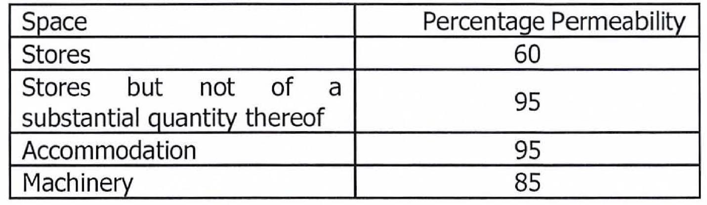
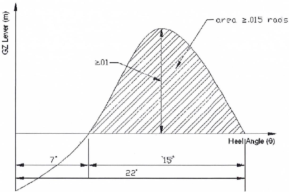
11.3.4 In the damaged condition, considered in 11.3.1, the residual stability should be such that any angle of equilibrium does not exceed r from the upright, the resulting righting lever curve has a range to the downflooding angle of at least 15° beyond any angle of equilibrium, the maximum righting lever within that range is not less than 100mm and the area under the curve is not less than 0.015 meter radians.
11.4
11.3.5 A yacht of 85 meters and above should meet a SOLAS one-compartment standard of subdivision, calculated using the deterministic damage stability methodology.
Elements of Stability
11.4.1
Unless otherwise specified, the lightship weight, vertical center of gravity (KG) and longitudinal center of gravity (LeG) of a yacht should be determined from the results of an inclining experiment.
11.4.2
An inclining experiment should be conducted in accordance with a detailed standard which is approved by the Administration and, in the presence of an authorized surveyor.
11.5
11.4.3 The report of the inclining experiment and the lightship particulars derived should be approved by the Administration prior to its use in stability calculations. At the discretion of the owner(s)/operator(s)/manager(s) and prior to approval of the lightship particulars by the Administration, a margin for safety may be applied to the lightship weight and KG calculated after the inclining experiment. Such a margin should be clearly identified and recorded in the stability booklet. A formal record should be kept in the stability booklet of alterations or modifications to the yacht for which the effects on lightship weight and vertical centers of gravity are offset against the margin.
11.4.4
When sister yachts are built at the same shipyard, the Administration may accept a lightweight check on subsequent yachts to corroborate the results of the inclining experiment conducted on the lead yacht of the class.
Stability Documents
11.5.1 A yacht should be provided with a stability information booklet for the master. The booklet is to be approved by the Administration.
11.5.2 The content, form and presentation of information contained in the stability information booklet should be based on the model booklet for the yacht type (motor or sailing) published by/for the Administration.
11.5.3 A yacht with previously approved stability information which undergoes a major refit or alterations should be subjected to a complete reassessment of stability and provided with newly approved stability information. A major refit or major alteration is one which results in either a change in the lightship weight of 2% and above and/or the longitudinal center of gravity of 1% and above (measured from the aft perpendicular) and/or the calculated vertical center of gravity rises by 0.25% and above (measured from the keel). Additionally, unless it can be clearly demonstrated that no major change has occurred, a lightweight check should be carried out at the renewal survey required in Part D, Section 3.
11.5.4 Sailing yachts should have, readily available, a copy of the 'Curves of Maximum Steady Heel Angle to Prevent Downflooding in Squalls', or in the case of a multihull, the values of maximum advised mean apparent wind speed, for the reference of the watch keeper. This should be a direct copy taken from that contained in the approved stability booklet.
11.5.5 The overall sail area and spar weights and dimensions should be as documented in the yacht's stability information booklet. Any rigging modifications that increase the overall sail area, or the weight/dimensions of the rig aloft must be accompanied by an approved updating of the stability information booklet.
11.5.6 For Short Range Yachts, where the damage stability has not been assessed, the following note should be added to the approved stability booklet: "This yacht has not been assessed for damage stability, and therefore might not remain afloat in the event of damage or flooding."


