7 minute read
Residential Trip to Canterbury
RESIDENTIAL TRIP TO CANTERBURY
The residential trip was a three day trip designed to get us started with the making of the project. However, there was also a lecture in the morning to explain the layout of the university and who we would be able to ask for assistance with any machines or specific needs.
Advertisement
Before we left for Canterbury, we already had a clear idea of what we wanted to do. Our main aims were:
1. Calculate the mass distribution, centre of mass and buoyancy 2. Research into suitable modelling materials for the construction of the scale model 3. Construct the scale model as accurate as we could 4. Test materials for a buoyancy aids 5. CAD Drawings of the tower
However, as we tackled these, the testing of the flotation devices was not completed as we didn’t have enough materials to test and so decided to leave this until we returned home and had completed the model.
The calculations for the mass distribution, centre of mass and buoyancy were obviously our major priority and little other than the structure could be produced before these were done, so half of our team set off and spent the majority of the first day working on these tasks. For further details into the exact methods and numbers involved in this please view the ‘Mathematics Behind the Design,’ which works throughall the calculations involved in this and the rest of the design process.
Research into Suitable Materials for the Model:
As we began to plan the model, quick attention was drawn to the fact that it would have to replicate the real thing in the water. This would mean that we should try to replicate the thicknesses and densities of each section. Upon research, it was found that aluminium had a density of 2700kg.���� −33 and so would suit our needs for the high density concrete that was 2500kg.���� −34. Similarly we found that PVC had a density of 1400kg.���� −35 which was relatively close to the lower density concrete at 1800kg.���� −36. This at the time seemed like a good idea until we realised that although these had similar densities, the thickness of each would be hard to match. We decided then to use these materials but to also used added masses internally which would help reproducethe same centre of mass.
After these conclusions were made, we decided to find the best matches that we could for the items that we needed. We realised that the university had an abundance of aluminium and we also found some PVC. However, the only PVC tube that we could find to make the central cylinder was 10.4cm instead of 8cm. This is the only area of the plan which was not accurately represented in the model.
The Making Process of the Model:
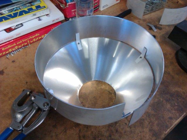
Firstly we began by cutting a circle which was to be the base. This was done with relative ease on a band saw. The next stage was to mark on this the location for all of the components which would be attached such as the lower ring and the central column. This was done by using a piece of string and a score used as a compass to mark the centre by drawing small sectors as close to the middle as possible. We could then determine the centre by eye. Secondly we cut out a sheet of aluminium the same size as the lower ring. This was the correct height and the length of the circumference of the lower ring. We actually decided to cut it slightly larger in length so that when it is bent around, it fits flush end to end. This was later rolled into the correct curvature to create the correct sized ring. The central column was then cut to length of 49cm to allow for the 1cm thick base.
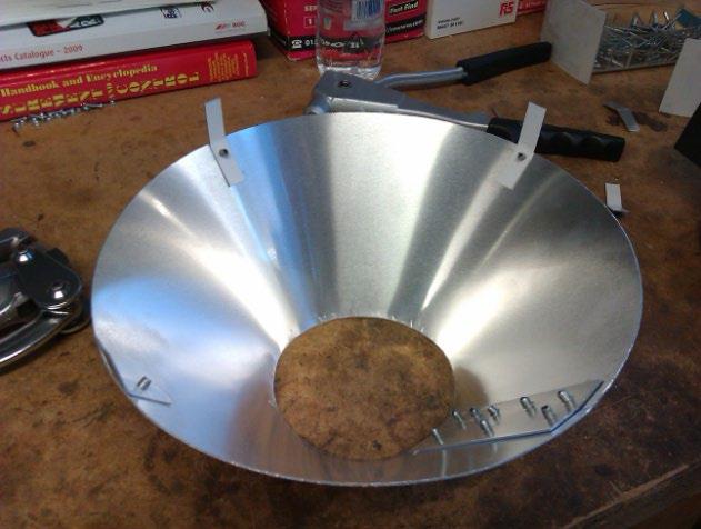
The next stage was the hardest: creating the conical shape between the lower ring and the central column. This was done by measuring the two circumferences; the top and bottom and then marking these from the same origin. This was cut out and then rolled using the same technique as the lower ring. However, because it is conical, you can’t simply feed it through the rollers in the same way we did for the lower ring, it had to be twisted at the same time. This was extremely time-consuming as it kept getting stuck in the rollers when it got close to the correct shape. Once this was completed, the first major problem occurred. We realised that the smaller circumference used in the marking out stage was 8cm as it should be instead of 10.4cm to fit the only available tube that we had for the central column. We decided to file it down as rolling it took a long time for which none of us were prepared to do again.
The next stage was to attach the lower ring and the conical section. For this we decided to rivet the two piece together using brackets that we had to make ourselves. The brackets had to be cut out, drilled or hole-punched and then bent tothe correct angle for the join. The two sections were then joined with the rivet gun. This was also a hard section of the build as we found it hard to create a flush fit between the two sections. We decided to test fit this complete module over the central column and onto the base disk to ensure that no other mistakes had been made. Much to our relief, there weren’t any.


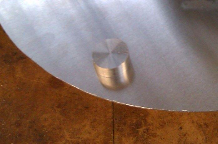
As I had previously stated, the base was to be 1 cm thick however, we had only managed to find aluminium that was 2 and 3mm thick. We decided to add feet to the design which could also help the unit to bed down into the silt and sand at the bottom of the ocean. These were created on the lathe and then a hole was cut in the middle of them. We then tapped out a thread in this hole to allow for them to be attached via a bolt through the base.
Having created all sections of the model, it was then time to assess its weight and how we should distribute this. Following on from the calculations of the centre of mass, we needed to add mass to the top and bottom sections and so the correct mass was created from a solid steel rod. This was turned on a lathe to remove rust and some weld deposits. The next stage was to drill a hole in the centre and then tap a thread into the block. This would allow us to move the weight to the correct height. Some stud bar was then cut down to length and attached through a hole in the base of the model. The weight was then attached and set to the desired height.
We then turned our attention to the weight for the top section. This was created from a thick aluminium tube then had a hole drilled through it sideways. We then cut some smaller stud bar down to length and attached this through two holes halfway up the top section of the column. We were extremely lucky as the tapped holes in the aluminium lined up correctly so that the thread wasn’t half a turn out.
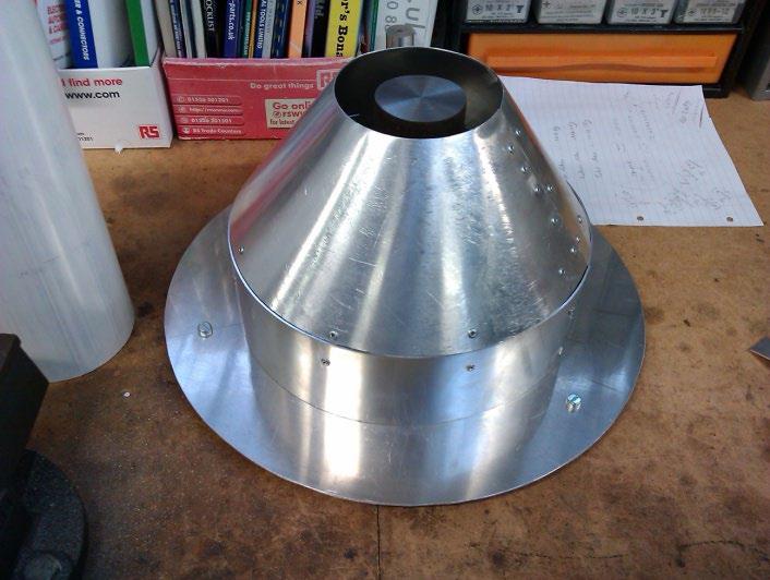
Lastly we decided to assemble the whole product. This did not just include assembly but also attaching the lower ring and conical section to the base. This was done in a similar fashion as with the lower ring and conical section. We simply created some brackets, this time at right angles, and then pop riveted the two together. Upon completion, it was decided that as the unit had to be watertight, we would need to seal it in some way. This is a problem that we hadn’t contemplated and so as a group decided to use some form of bathroom sealant. This would be done at a later date most probably back at school.


