10 minute read
Probing For HTHA


Daly Souissi, Olympus, Canada, explores a new strategy for HTHA inspection.Daly Souissi, Olympus, Canada, explores a new strategy for HTHA inspection.
The high-temperature hydrogen attack (HTHA) damage mechanism is a critical concern in ammonia plants, refineries and other petrochemical facilities. The operating conditions (e.g. temperature, hydrogen partial pressure [HPP], stress, in-service duration, etc.) of processing equipment in these types of facilities increase the risk of HTHA occurring.
Monitoring the integrity of the equipment components for HTHA is necessary to avoid failures
he high-temperature hydrogen attack and accidents; however, inspecting for such (HTHA) damage mechanism is a critical damage is challenging and requires a specific concern in ammonia plants, refineries strategy using a range of techniques in accordance and other petrochemical facilities. The with API RP 941. operating conditions (e.g. temperature, hydrogen In this article, the focus will be primarily on partial pressure [HPP], stress, in-service duration, HTHA inspection using advanced ultrasonic testing etc.) of processing equipment in these types of (UT) techniques, including focused phased array UT facilities increase the risk of HTHA occurring. (PAUT), full matrix capture (FMC)/total focusing
Monitoring the integrity of the equipment method (TFM) and Dual Linear ArrayTM (DLA). A components for HTHA is necessary to avoid failures specific case study will be discussed.


and accidents; however, inspecting for such damage is challenging and requires a specific strategy using a range of techniques in accordance with API RP 941.
In this article, the focus will be primarily on HTHA inspection using advanced ultrasonic testing (UT) techniques, including focused phased array UT (PAUT), full matrix capture (FMC)/total focusing method (TFM) and Dual Linear Array (DLA). A specific case study will be discussed.



HTHA is the result of hydrogen diffusing through steel over an extended time period. This, in conjunction with high HPP and elevated temperatures above 200˚C (400˚F), often leads to a decarburisation process that consists of a reaction between the precipitating carbon and the hydrogen that forms methane (CH4) around material grain boundaries. Methane bubbles (voids) progressively form in solid steel over time, creating stresses and fatigue that lead to microfissures and, ultimately, to cracks.
In the early stages, HTHA voids typically initiate near the internal diameter (ID) and evolve, at first, to micro (50 – 100 μm) then macro (>100 μm) fissures that steadily connect and grow into larger cracks that may extend to the outer diameter (OD). The HTHA cracking stage is the most severe, as it may result in the component’s failure.
It is hard to predict the HTHA evolving mechanism as it depends on several environmental factors, including HPP, the operating temperature and the duration of the exposure, in addition to the composition of both the base metal and the weld metal.
Inspection challenges
In the non-destructive testing (NDT) industry, inspecting for HTHA is considered to be one of the most challenging UT applications due to the complexity of the damage. Detection: early stages of HTHA are very difficult to detect because of the small size of the voids, especially in thick material. Characterisation: generally, suspected indications are not easily identified as HTHA. They could be confused with base-material imperfections, other weld defects – such as porosities and inclusions – and even with noise from the material grain. Sizing: when reporting indications as HTHA, the inspector needs size information to determine the current damage stage and assess whether the component is fit for continued service. Accurately sizing micro and macro voids continues to be a challenging task, even though sizing techniques have evolved. Accessibility: when inspecting a weld for HTHA, an additional difficulty may be faced when the component’s design allows only one-sided access (e.g. weld to elbow, weld to cone, transition of thickness, etc.). A single-sided access weld eliminates the use of time-of-flight diffraction (TOFD), which is an important technique, and leads to more signal attenuation when Table 1. Test strategy details inspecting the far side of the Technique Probe Wedge No. elements/ Angle˚ weld.
focal law range
To tackle all these challenges, it is recommended to combine several UT techniques and select adequate equipment and tools in accordance with a specific inspection strategy.
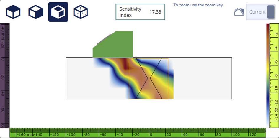
Figure 1. AIM wave set simulation and sensitivity index for the TFM transverse-transverse (T-T) model, using a 10L64 A31 probe mounted on a SA31 N55S wedge.
FD
PAUT: SW 10L64 A31 SA31 N55S 32 40 – 72 35
TFM: T-T 10L64 A31 SA31 N55S N/A N/A N/A
DLA 10DL32-9.6X5-A28 SA28 N65L - FD25 32 0 – 80 40

Figure 2. Location 1 – indication colonies as observed in the DLA inspection results. B-scan (side view) shows the extent to be 110 mm along the weld axis, while the S-scan shows that indications are in the near-side zone.
Inspection strategy
Generally, for a given inspection, the strategy is part of the inspection procedure and includes these technical details: inspection equipment, scan plans and patterns, calibration process, etc. An HTHA inspection strategy should be based on the latest API RP 941 guidance.
API RP 941 past editions recommended several UT techniques developed in the 1980s and 1990s, including velocity ratio, frequency and spectral analysis and conventional backscattering.
Annex E of the latest revised edition, however, recommends a new inspection approach based on TOFD, PAUT and FMC/TFM techniques using the highest practical frequencies (7.5 MHz – 10 MHz). TOFD: TOFD is the first and primary screening tool, as it is faster and more sensitive compared with other methods. Although TOFD detection can easily provide the location of indications, it does not offer a conclusive distinction between HTHA and inherent inclusions or porosities. Highly focused PAUT Pulse-Echo (P/E): suspected indications found using TOFD are assessed using the
PAUT P/E technique. Configurations should be carefully set up with adequate probes and focal laws (voltage, focus, number of elements etc.). Based on
TOFD findings, the generated beams should be focused at the targeted depth to improve detection and resolution capabilities. FMC/TFM: FMC/TFM can be used as an additional confirmation method. The probe and configurations should be selected carefully to ensure the full imaging benefits of these advanced techniques. In TFM, it is important to use a modelling tool, such as the Acoustic Influence Map (AIM), to help ensure the optimal choice of probes. Transmit-Receive-Longitudinal (TRL) technique: the TRL technique, using DLA and Dual Matrix ArrayTM (DMA) probes, is a strong alternative to PAUT P/E. TRL configurations offer an improved signal-to-noise (SNR) ratio, better lateral sizing capabilities, higher depth focusing capabilities and no subsurface dead zone.
Case study: inspection for HTHA in a single-sided access weld
Context
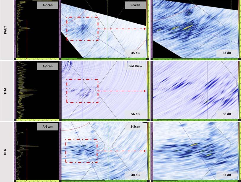
Figure 3. Location 1 indications as observed in PAUT, TFM and DLA acquired data.
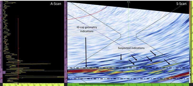
Figure 4. DLA technique data showing low-amplitude and low-density indications near the bottom cap of the weld’s far side.
Figure 5. DLA sectorial scan showing geometric indications interfering with suspected indications. In this case study, tests were conducted on a carbon steel sample cut from the shell-to-head joint of an aged pressure vessel. The 50 mm thick sample contained a double V weld with non-grinded top cap. Only one side was accessible, so TOFD was used to assess the base material near the weld but could not be used to inspect the weld. Only PAUT, FMC/TFM and DLA techniques were carried out from the accessible side of the weld.

Inspection strategy
As a replacement for TOFD, an unfocused PAUT configuration was used as a primary screening tool on the weld. The resulting scans showed that suspected indications were located at depths between 30 mm and 45 mm. The focal depth (FD) was adjusted accordingly for all subsequent deployed techniques. After preliminary tests showed poor detection capabilities with longitudinal waves (LW), the PAUT P/E and TFM were set to shear wave (SW) mode. The same 10 MHz 64-element A31 probe was used for both techniques.
The wave set selected for the TFM was transverse-transverse (T-T). The selection of the optimal probe and mode in TFM was based on the AIM and the sensitivity index (SI), as shown in Figure 1.
An angular DLA technique was used to improve coverage and detection on the weld
far-side area. The deployed probe was the 10 MHz dual 32-element A28 probe. Its small footprint adapts to areas with restricted accessibility while maintaining a high acoustic performance and improved coverage of the weld and heat-affected zone (HAZ). The PAUT unit used was the Olympus OmniScanTM X3 32:128PR model. Table 1 summarises the probes and configurations that were used.
The sensitivity level was set using a 1 mm side-drilled hole (SDH). The gain was obtained by adding 12 to 18 dB during the scan.
Results
The TOFD examination of the base material revealed no relevant indications, whereas the weld inspection identified two locations containing indications with HTHA-like patterns.
In the first location, indications were detected between the double V root and the HAZ of the weld in the near-side zone (accessible side). In the second location, indications were detected near the ID surface in the weld’s far-side zone and could not be confirmed as HTHA.
Location 1
As seen in Figure 2, the suspected indications have void-like shapes and are present as dense colonies along a 110 mm distance in the weld axis. No cracking is observed, and the indications were assessed to be smaller than 1 mm, which suggests that the damage is still in the early stages. As shown in Figure 3, these indications were detected by all three deployed techniques; however, a better SNR ratio and a higher resolution were obtained with the DLA acquired data.
Location 2
Figure 4 shows low-amplitude and low-density indications in the inferior area of the weld’s far side. In this area, several geometric indications are observed due to the weld’s ID surface geometric reflections, which interfere with the suspected indications, as displayed in Figure 5. Better SNR and improved detection and resolution were observed in the DLA acquired data in comparison with the PAUT and TFM data (Figure 6). The indications are smaller than 1 mm and could not be characterised as HTHA with certainty. Metallographic testing should be conducted to verify the UT interpretations.
Discussion
For this inspection of a single-sided access weld with a non-grinded cap for HTHA, in addition to the inability to use TOFD, standard PAUT and TFM techniques showed detection and resolution limitations in the far-range zone (opposite side). Better results were obtained with the DLA TRL technique using the A28 probe.
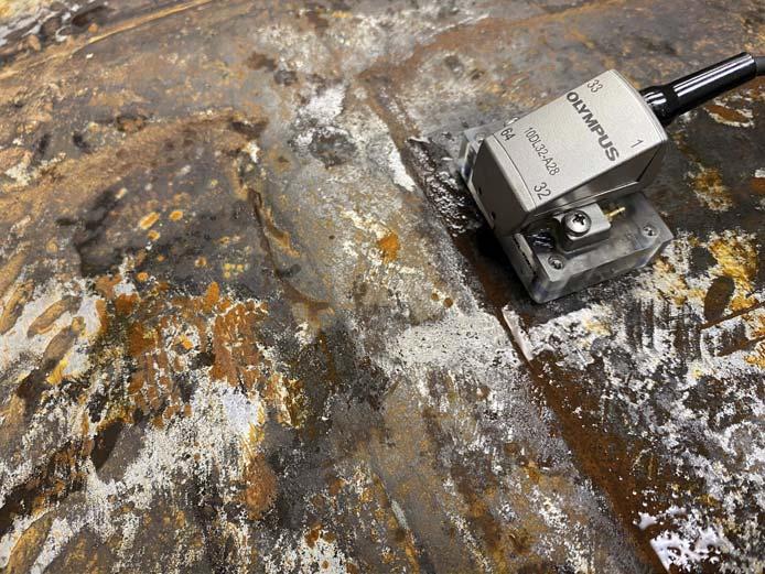
The angle-beam A28 probe features a pivoting hinge system that enables the transmitting and receiving elements to be as close as possible. The proximity of the arrays expands the thickness range at which the beam can be electronically focused. Due to its pivoting housing, the probe has a longer focal range, which can increase the probability of detection in the far range compared with PAUT, TFM and other DLA probes. A photo of the A28 probe is displayed in Figure 7.
Conclusion
The results of this study demonstrate that the DLA technique should be considered as part of HTHA inspection strategies as an additional beneficial tool in combination with TOFD, PAUT and TFM.
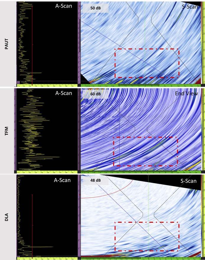
Figure 6. Location 2 indications as observed in PAUT, TFM and DLA data.
Figure 7. Photo of DLA A28 probe during manual scanning for HTHA detection.
