12 minute read
An alternative route


Ghith Al Shaal, Christoph Hauber, Ioan-Teodor Trotus, and Fabian Schneider, hte GmbH, Germany, explore the utilisation of pyrolysis oils in the production of fuels and chemicals.


Nowadays, economies and industries are heavily reliant on limited fossil-based resources that do not contribute to a circular economy. In this context, a continuous sustained effort is required to shift gear towards more sustainable and renewable resources. An increasing number of governments and companies have taken the initiative to integrate circular economy in their politics and regulations to minimise their carbon footprint. Two essential factors in this transition process are the utilisation of alternative feedstocks and the minimisation of process waste by increasing process effi ciency and recycling process waste. Both factors are highly entwined, since the waste of one process can be the alternative feedstock for the other process. In a previous article that featured in the September 2020 issue of Hydrocarbon Engineering, one instance was shown of hte supporting research to minimise the carbon footprint through the use of bio-derived synthesis gas followed by Fischer Tropsch synthesis and hydrocracking of the wax products to produce synthetic fuels.1 While this approach is elegant, it is also very energy intensive. In this article, an


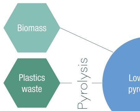
Figure 1. Starting materials for pyrolysis oil production.
alternative route with lower energy consumption will be discussed, and ways in which laboratory catalyst testing can support R&D in this fi eld will be described. This route avoids the production of bio-derived synthesis gas via the utilisation of pyrolysis oils in the production of fuels and chemicals.
Pyrolysis oils can be defi ned as the liquid product of a fast heating process at short to medium contact times, in an oxygen poor atmosphere, applied to a wide variety of feedstocks (Figure 1). The feedstocks include biomass such as residual agricultural products, wood, and waste from paper production, and these pyrolysis oils are also called bio-oils. Another feedstock that can be used in the production of pyrolysis oil is plastic waste. This can be post-consumer plastic waste or end-of-life tyres which, in the worst case, would end up in landfi lls without recycling. The defi ned structure of the pyrolysis oil is not fi xed, and it always depends not only on the feedstock used in the process but also on the process parameters including temperature, reactor design, presence of catalysts, pyrolysis time, etc.
Pyrolysis offers numerous advantages as it positively contributes to the defossilisation process by offering an alternative solution in the transportation sector while also offering a solution for the growing global landfi ll crisis. Thus, it contributes to closing the value chain cycle by saving on raw materials and enabling more versatile recycling of waste. These factors present solutions toward a more sustainable circular economy and have attracted the attention of many industries, including refi neries.
With refi neries experiencing a very unprofi table period due to COVID-19 and travel restrictions keeping kerosene demand at historically low levels, investments in new units are less likely and drop-in solutions for integrating renewable feedstocks in the existing units seem more probable. Developing a strategy to handle the above concerns with pyrolysis oil conversion in a refi nery, even as a co-feed, is a great way to decrease a refi nery’s carbon footprint. Finding the right feed composition and the optimal catalysts converting highly diverse pyrolysis oils requires a large number of catalytic tests with a smart design of experiments. To speed up the process and catalyst development, high throughput testing is mandatory.
Waste refinery concept
Many refi neries have already considered steps to increase the effi ciency of fuel production. In this regard, FCC, hydrotreatment, and hydrocracking units were integrated to upgrade the secondary stream coming from the refi nery to gasoline, diesel, and chemicals such as monomers or aromatics. These technologies can also be used to process the pyrolysis oil and upgrade the outcomes of the pyrolysis process toward fuels and chemicals. Yet, by integrating the upgrading process of pyrolysis oil in the workfl ow of the FCC and hydrotreatment unit, the refi neries will be able to produce a sustainable fuel with a smaller carbon footprint and with lower consumption of fossils. This concept is known as waste refi nery and could be applied on pyrolysis feed only or a mixture of pyrolysis oil and low-quality stream from oil (e.g. VGO). The later process is known as the co-processing of pyrolysis oil and oil residue.
While fuel production is one possible and convenient application, there is also an emerging trend for the petrochemical industry, especially in Europe, to offer fully recycled plastic products. This is an alternative for plastics producers to circumvent restrictive policies by which more and more single-use plastic products or plastics with a very short lifespan (such as packaging) are being banned. Instead of reducing plastics consumption, sustainable recycling offers the chance to keep the quantity of plastics in use at a high level in a CO2- and waste-neutral manner. With the known limitations of mechanical recycling and plastics sorting being a ponderous and costly process, one pragmatic approach in chemical recycling of plastics wastes is the use of mixed-plastics feedstocks (e.g. from municipal solid waste that is not suitable for mechanical recycling), and to tune the pyrolysis step itself toward a maximum yield of short-chained monomers directly or feedstocks that will be used in state-of-the-art technology that already converts mixtures of hydrocarbons into light olefi ns – particularly FCC and naphtha crackers.
Purifying = valorisation
The starting materials for pyrolysis oil production, whether waste plastics or biomass-derived sources, along with the conditions for the pyrolysis process itself, will determine the chemical composition of the product pyrolysis oil. One must keep in mind that pyrolysis alone will probably produce a condensed liquid product which is highly reactive due to the presence of reactive oxygenates and/or unsaturated compounds. Without applying any stabilisation, pyrolysis oils could even be unstable for storage at room temperature. Feeding or co-feeding pyrolysis oils in a refi nery unit requires developing a stabilsation strategy – this can be, for example, a low-temperature hydrotreatment step applied immediately after pyrolysis to saturate the most reactive olefi ns and dienes and/or to remove the most reactive oxygen atoms. This can also help to reduce the free-carboxylic-acid acidity of pyrolysis oils, although

this alone is not the greatest corrosion risk, as will be discussed in this article.
In the hydrotreatment of pyrolysis oils, the relative instability of these feeds already needs to be considered in terms of the feed-handling procedures. Even for pyrolysis oils that have undergone some stabilisation treatment, care must be taken to not overheat these to avoid the buildup of particulate matter due to polymerisation reactions.
In fi xed-bed hydrotreatment applications, even with pre-stabilised pyrolysis oils, the more common approach is to fi rst react the feed at a relatively low temperature, either in a separate reactor or by applying a cooler inlet temperature and increasing the temperature toward the lower catalyst beds. In this manner, one can saturate and deoxygenate more of the reactive species (olefi ns or oxygenates) while minimising the chance for polymerisation reactions, which can clog a reactor. As shown in previous publications, hte has options for connecting reactors in series both in high-throughput (1 – 10 milliliters [mL] catalyst volume) and in bench-scale units (20 – 100 mL catalyst volume) which can be used to support pyrolysis oil conversion studies.2,3,4
Once a reliable stabilisation, handling, and storage procedure for the pyrolysis oils is established, converting a pyrolysis oil to a fuel or to chemicals bears more similarities to conventional processes applied in oil refi ning.
New challenges of (hydro-)processing
Hydrotreatment to remove heteroatoms such as sulfur and nitrogen from oil fractions is a standard process in every refi nery. Sulfi de-type catalysts of the metals Co, Ni and Mo are most frequently used in the hydrodesulfurisation (HDS) and hydrodenitrogenation (HDN) of oil fractions. Pyrolysis oils resemble crude oil fractions in that they contain carbon, sulfur, and nitrogen, but pyrolysis oils will also contain signifi cantly higher amounts of oxygen or chlorine than crude oil fractions. Other elements that can be found in pyrolysis oils include fl uorine and bromine, as well as sodium, potassium, calcium, and phosphorus. The elemental composition of the pyrolysis oils determines some of the challenges involved when converting it to fuels or chemicals. Metals and phosphorus can act as catalyst poisons, but there are strategies for keeping their effects in check, either by employing a washing step or with the use of guard beds.
The combination of chlorine and oxygen in one feed means water and hydrochloric acid (HCl) will be among the products of a hydrotreatment step. In this context, corrosion can become an issue. The greatest risk of corrosion is not simply from the presence of hydrochloric acid in itself or from the carboxylic acid groups of the compounds in the oil, but rather the possibility of having liquid water droplets condensing downstream of the reactor where they can also dissolve the HCl product and slowly corrode steel parts. With 316-grade stainless steels, one strategy that can be applied to mitigate corrosion is to simply ensure that water cannot condense downstream of the reactor by heating this part of the pilot plant to temperatures above the dew point.
Oxygen removal is usually performed via hydrodeoxygenation (HDO) or decarboxylation/ decarbonylation. The HDO reaction can be catalysed by the same types of metal sulfi de catalysts used for HDS and HDN reactions. However, in hydrotreatment processes of crude oil fractions, the high sulfur content of the feeds also ensures that the active species remain in the sulfi de form. Depending on the catalysts and reaction conditions, the hydrotreatment of pyrolysis oil with low sulfur content might require spiking the feed with compounds containing sulfur (such as dimethyl disulfi de) to avoid the loss of sulfur from the catalysts’ active phase.
Oxygen removal results in the production of CO or CO2 or in the production of water. Ideally, one would prefer to minimise CO/CO2 production to maximise the carbon atom effi ciency. Even without affecting the carbon effi ciency, water as a product also brings some special challenges. Aside from the possible corrosion issues referred to above, water also makes product analysis more diffi cult because the liquid product consists of an organic and an aqueous phase which must be separated.

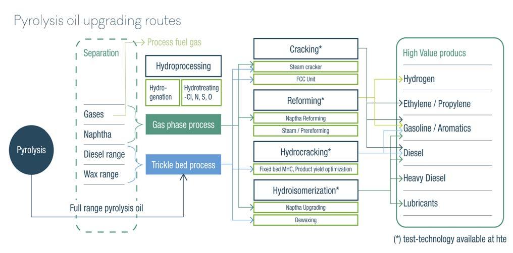
Figure 2. Schematic overview of processes where pyrolysis oils can be converted in a refinery.
The right fit
Hydroprocessing and cracking (FCC and/or steamcracking) processes are the available means of integrating the upgrading of pyrolysis oils in existing refi neries or chemicals production complexes.
Choosing a suitable combination of a pyrolysis reactor, product fractionation, and upgrading or refi ning steps will play a major role in making the use of plastics-derived or biogenic pyrolysis oils a rewarding investment.
Analysis
Finding the right catalyst and the right process condition for the conversion of pyrolysis oil can benefi t greatly from running many tests to replicate the industrial process conditions in a laboratory. Figure 2 offers an overview of possible pyrolysis oil conversion routes, highlighting the processes. The two main types of processes applied in the upgrading of pyrolysis oils are fi xed-bed hydroprocessing applications or short contact time cracking applications. Regardless of which is selected, hte can support process research with catalyst testing projects or by providing testing equipment for these applications.
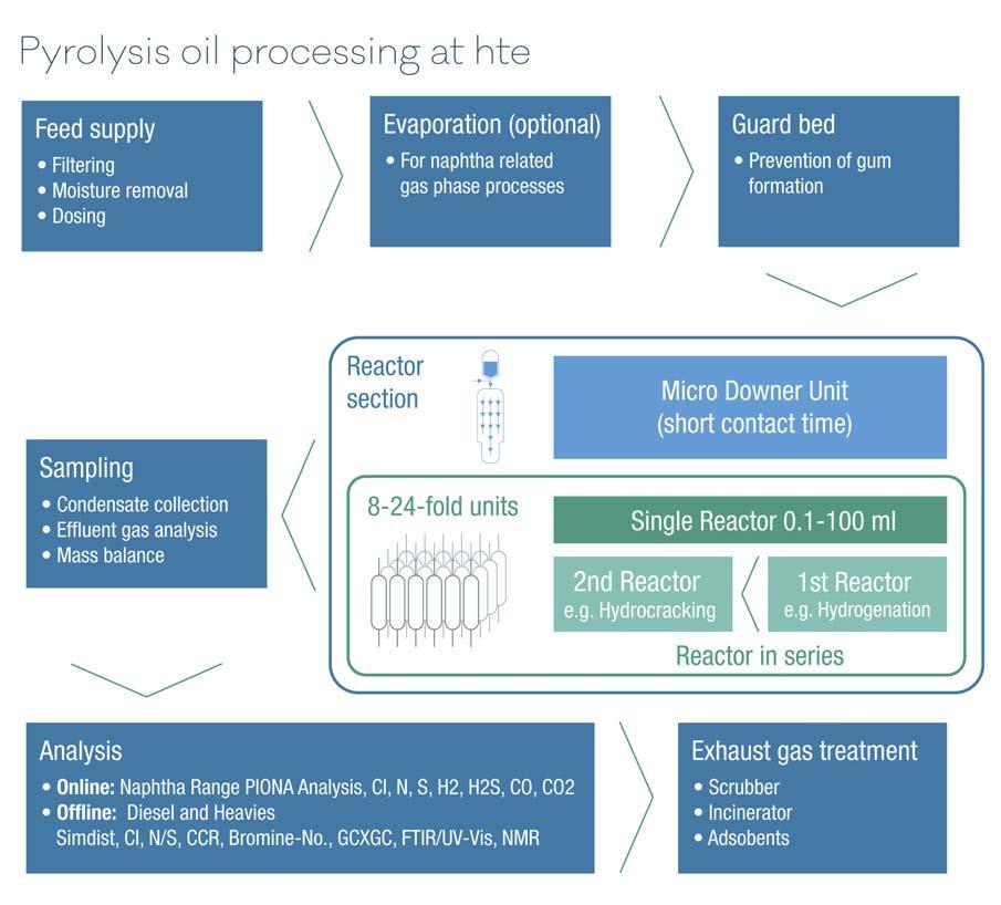
Thus, the complex nature of pyrolysis oils has been investigated and the most common challenges for the laboratory equipment can be addressed (Figure 3 offers a schematic overview of these): Feed supply Direct usage of a full-range pyoil requires special pumping equipment that covers extreme boiling point ranges with light components tending to gas out at high temperatures and waxy residue potentially clogging parts of the unit at low temperatures.
Standard refi nery processes are best addressed with offl ine analysis of the liquid samples. Offl ine analysis of liquid samples includes S/N analysis, pH measurements, simulated distillation, XRF, cloud point/pour point, etc. The analysis of pyrolysis oils and their reaction products also requires the use of more specialised analysis techniques such as high-performance liquid chromatography (HPLC), 2D gas chromatograph (GC), and nuclear magnetic resonance (NMR). Aside Figure 3. Workflow for investigating pyrolysis oil conversion processes on a laboratory scale. from these offl ine analysis techniques, the test unit should be equipped with a GC that offers detection of light hydrocarbons and non-organic effl uents such as H2S, CO, CO2, and hydrogen. Additionally, for a complete assessment of heteroatom concentrations in low-boiling naphtha fractions and light hydrocarbons, the integration of online detectors for sulfur, nitrogen, and heteroatoms is the best choice to gain a deeper understanding of the product quality, as this determines if a pyrolysis-oil-derived product is suited for further processing in a cracking unit with very specifi c limitations toward impurities.
Conclusion
Pyrolysis oils offer a pragmatic solution for both reducing the amount of waste in landfi lls and for decreasing the carbon footprint associated with fuels and chemicals derived from fossils. Before processing pyrolysis oils into a refi nery or chemicals production complex, a large number of experiments are required to ensure that their use can generate the desired product properties and to evaluate how the long-term use of pyrolysis oils as a feedstock impacts catalyst performance. In this endeavour, hte can offer testing solutions for both fi xed-bed and short-contact-time fl uidised bed processes to aid in fi nding the best conditions for converting pyrolysis oils to fuels or chemicals.

Reactor setup
Investigating hydrocracking catalysts cannot be done without a thorough pre-treat, while a hydrocracking catalyst offers some hydrotreating capabilities in itself – a combination of a set of the different type of catalysts renders a catalyst screening effective, as one can choose to vary temperatures, load different ratios or combinations of catalyst samples, and screen all these parameters at the same time. As for short contact time processes, the developed workfl ows for feed supply and analytics can be implemented in a micro downer unit, which most effectively simulates FCC operation under industrially relevant conditions.
References
1. ROBERTS, T., DANNENBAUER, K., and HUBER, F., ‘Test for Success’,
Hydrocarbon Engineering, (September 2020), pp. 49 – 52. 2. TROTUS, I-T., ADELBRECHT, J-C., HUBER, F., PONGBOOT, N. and
UPIENPONG, T., PTQ Catalysis, Vol. 24 No. 5, Q4 2019, pp. 79 – 83. 3. DANNENBAUER, K., TROTUS, I-T, HENKEL, R. and HUBER, F., ‘Testing times’, Hydrocarbon Engineering, (November 2020), pp. 27 – 30. 4. DANNENBAUER, K., TROTUS, I-T, HENKEL, R. and HUBER, F, ‘Going head-to-head’ Hydrocarbon Engineering, (March 2021), pp. 53 – 56.


