
79 minute read
Everything In Moderation


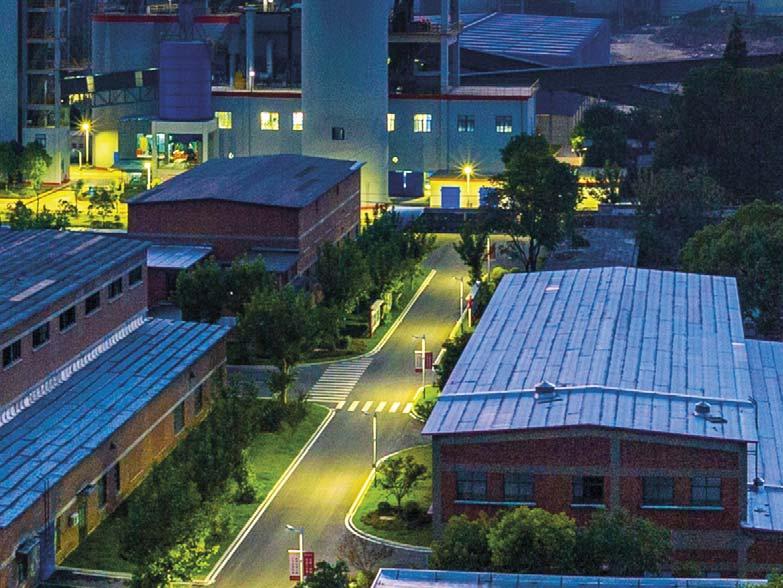
Wang Lan, China Building Materials Academy, discusses the installation and operation of a moderate temperature SCR Reactor for ChangXing Southern Cement Company.


EVERYTHING IN


MODERATION
The high temperatures in rotary cement kilns result predominately in the formation of NOx. Without emissions control measures, the NOx concentrations in the fl ue gas of rotary kilns are in the range of 800 to 1800 mg/m3. In China, there are about 1650 cement production lines, producing around 2.4 billion t of cement and 1.55 billion t of clinker in 2020. Calculated with the emission coeffi cient of 1.80 kg/t clinker, the yield of NOx is about 2.8 million t from the cement industry. This emission source is ranked third largest after the electrical power and transportation sectors in China. NOx is a severe air pollutant, and can lead to the formation of acid rain while also causing harm to human health. DeNOx is a top priority mission for the sustainable development of the cement industry.

China’s Cement Industry Emission Standard of Air Pollutants (GB4815-2013) set up limitation values for NOx emissions at 320 mg/m3 and 400 mg/m3 from cement kilns in different areas. However, several local governments have issued more stringent requirements, outlining that NOx emissions from cement kilns must be below 50 mg/m3 and NH3 slip below 5 mg/m3 if ammonia is used as reducing agent.
The best available technologies for DeNOx operations include primary measures and secondary measures. The former are based on the principle of reducing the excess oxygen levels and the peak fl ame temperature in cement kilns, for example by using a low nitrogen burner and staged combustion. However, the DeNOx effi ciency of the primary measures cannot exceed 50% without interfering with cement kiln operation. The latter includes SNCR (selective non catalytic reduction) and SCR (selective catalytic reduction) technologies, and they often use ammonia or other nitrogen-containing compounds with the chemical reaction: NH3 + NOx → N2 + H2O. Usually, DeNOx effi ciency of SNCR is controlled at 60%, otherwise it could lead to more NH3 slip, e.g. high emissions of unreacted ammonia. Compared to SNCR, SCR can achieve DeNOx effi ciency of up to 95% and it cause less NH3 slip, as the NH3 to NOx molar ratio can be controlled as 1:1. In order to limit NOx emissions to a low level of 50 mg/m3, the use of the SCR technique is necessary.
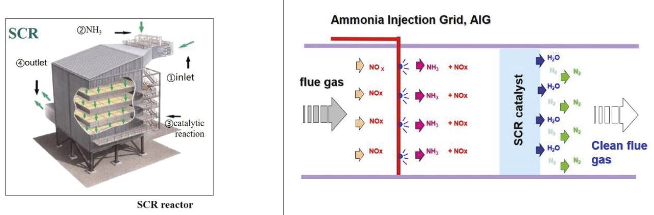
The key setup of the SCR technique involves a SCR reactor, which is a high tower with several layers of catalyst modules installed inside. Flue gas from the cement kiln mixed with injected ammonia is drawn into the reactor, where NH3 reacts with NOx quickly when passing through the channels of the Table 1. The parameters of the fl ue gas from the waste heat boiler. catalyst element (Figure 1).
No. Item Data Unit Note The temperature of fl ue gas exiting 1 Flue gas 380 000 m3/hr 710 000 (WC) the top of the 2 O2 < 4 % preheater is 3 Temperature 200 - 220 ºC about 320ºC, and the dust 4 SO2 < 300 mg/m3 O2 10% content of the 5 NOx < 300 mg/m3 O2 10% fl ue gas is about 6 Dust < 60 g/m3 O2 10% 120 g/m3. When exiting the waste 7 Moisture 4 % heat boiler, the temperature of the fl ue gas is reduced to about 200ºC, and the dust content is reduced to about 60 g/m3. The SCR reactors can be placed before the waste heat boiler (‘high Figure 1. NH3 reacts with NOx quickly in the SCR reactor. temperature confi guration’) or after the waste heat boiler (‘moderate temperature confi guration’). The ‘high temperature confi guration’ can also be classifi ed as a ‘high dust’ Figure 2. The layout of a moderate temperature SCR reactor. layout or a
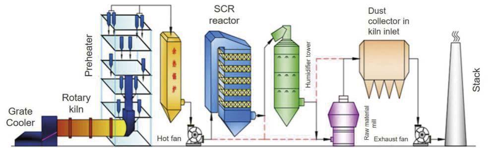
‘low dust’ layout. The ‘high dust’ layout has little effect on the effi ciency of the waste heat boiler, but has a high impact on the service life of catalyst material and on the DeNOx effi ciency of the SCR reactor. The ‘low dust’ layout requires a dust collector installed in front of the SCR reactor to lower the dust content of the fl ue gas to about 55 g/m3. This not only reduces the effi ciency of the waste heat boiler signifi cantly, but also complicates the SCR reactor system and increases the potential stoppage of the entire system.
‘Moderate temperature confi guration’ refers to the SCR reactor being arranged between the high temperature fan and the raw material mill system, as shown in Figure 2. It has the advantages of both ‘high temperature’ layouts. This SCR reactor has no effect on the effi ciency of the waste heat boiler. Due to the natural separation in the waste heat boiler, the presence of dust in the fl ue gas decreases from 120 g/m3 to 60 g/m3 before the fl ue gas enters the SCR reactor. Moderate temperatures will also result in a smaller volume of fl ue gas, thus allowing for smaller dimensions of the reactor, and in turn for lower construction investment and lower costs of the SCR reactor system.
In order to develop moderate temperature SCR techniques, research has been conducted into the raising of DeNOx activity of the traditional SCR catalyst. Some strong absorptive materials have been added to the catalyst to reinforce its adsorption of NH3 and NOx. Trace transition metals, such as W2O5, have been added to the catalyst to promote its moderate temperature activity.
After that, a semi-scale SCR reactor is installed with 3+1 catalyst for the examination of the function of the newly developed catalyst materials, as shown in Figure 3. In this semi-scale
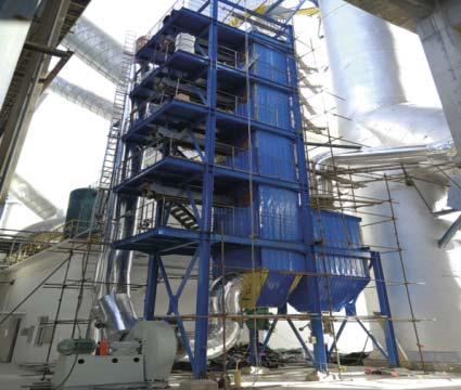
Figure 3. The semi-scale SCR reactor.


SCR reactor, each layer of catalyst has only one catalyst module. Flue gas of 10 000 m3/h from the cement kiln is drawn into the reactor and its temperature and the dust content are 200ºC and 60 g/m3, respectively. The NOx concentration in the fl ue gas from the cement kiln has been detected as up to 300 mg/m3, and due to the unreacted ammonia of SNCR in kiln system, its NH3 content has also been tested up to 120 mg/m3. In this case, a certain amount of ammonia has been added and injected into the SCR reactor to maintain the molar ratio of NH3 to NOx of 1:1. The semi-scale SCR reactor has been in operation for nearly two years, with DeNOx effi ciency up to 90%. This research work has confi rmed the feasibility of the moderate temperature SCR technique.
Figure 4. The design of a moderate temperature SCR reactor. Table 2. Major equipment and setup of the SCR reactor.

No. Equipment and setup Note
1 Reducing agent
2 Meter/jetting
3 Catalyst
4 Dust blowing
5 Compressor
6 Connected ducts and pipes
7 Dust delivery The initial storage tank of ammonia for SNCR was used and two new ammonia pumps were added.
A new set of meters were added and modules to control the dosage of ammonia were delivered. A new ammonia evaporator with 125% capacity was added.
Four catalyst layers were installed, and a fi fth layer was added as a backup.
Rake teeth blowers and acoustic soot blowers with compressed air were used.
Two new compressors were added, with one in operation and one on standby.
New baffl es were set up for original ducts and pipes.
A screw feeder to star feeder was added below the dust bucket.
8 Electrical & controlling Connections were made to the central control room and DCS system.
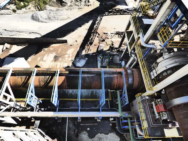
ChangXing Southern Cement Company is located in the Zhejiang Province, Changxing county. The company owns a 6300 tpd cement clinker production line with a rotary kiln of Ф4.8 x 72 m, a TDF precalciner and a waste heat boiler. A breakdown of the fl ue gas from the waste heat boiler is listed in Table 1. The production line has been added with the SNCR system, using up 350 l/hr of ammonia (20% concentration), and reducing NOx emissions to about 280 mg/m3 .
Considering the stringent upcoming requirements to lower the emissions of NOx to less than
50 mg/m3 and NH3 slip to less than 5 mg/m3 , the cement company decided to make use of SCR techniques – the moderate temperature confi guration was chosen for the plant design.
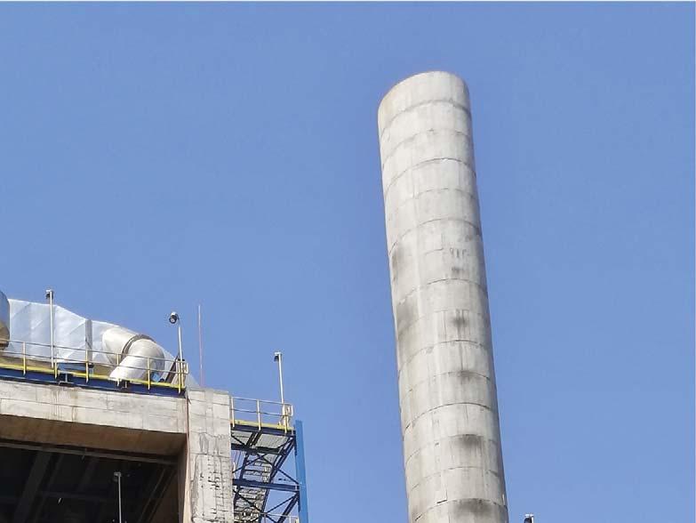
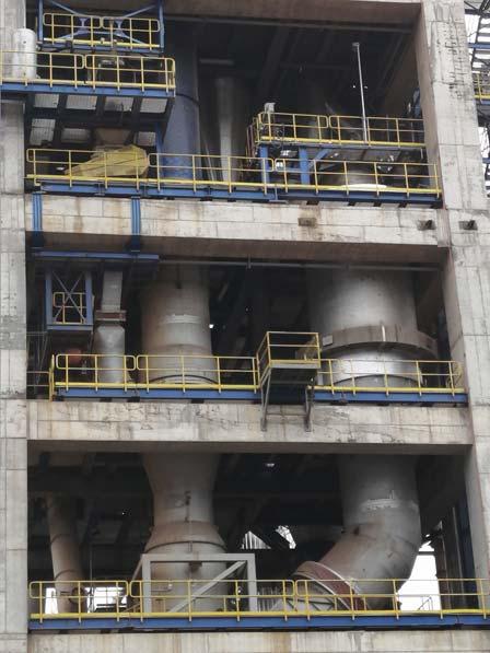
The designed SCR reactor (Figure 4) was placed after the waste heat boiler, with a section area of 64 m2, height of 34 m, and the whole tower of 350 t. Inside the SCR reactor, 4+1 catalyst layers were installed, and each layer has 48 modules. The whole volume of the catalyst used is about 200 m3. Around and above each catalyst layer, acoustic soot blowers and rack teeth blowers were fi tted to avoid the accumulation of the dust on the catalyst layer and to help convey the dust to a hopper at the bottom of the reactor.
CFD simulation analysis was conducted for the design of connected pipes to the reactor in order to optimise their arrangements. Defl ectors were set up in suitable positions inside the pipes in order to improve the uniformity of the fl ue gas and to prevent the creation of deviant dust currents, as deviant dust currents may cause severe abrasion of the catalyst materials and block up the cells of the catalyst.
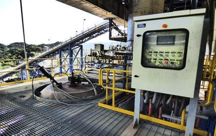
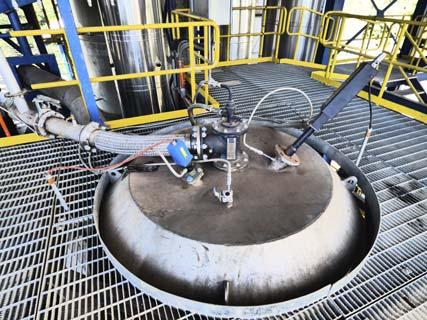
The SCR reactor was equipped with meters and gauges to detect and measure the pressures, temperatures and compositions of the fl ue gas, and to send all this data to the newly added DCS system for remote monitoring and daily start-stop of the reactor. The SCR reactor was attached to the ammonia injection system and can perform DeNOx by itself. It can also utilise NH3 slip from the SNCR system to perform DeNOx. The economy of both operation methods is under review based on the DeNOx effi ciency, the consumption of ammonia, the NH3 slip and the power consumption of the entire system. Major equipment and setups of the SCR reactor are listed in Table 2.
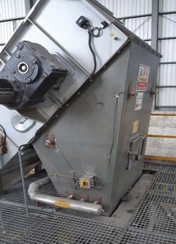
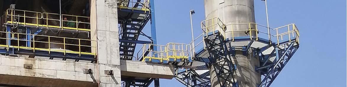
The construction duration of the SCR reactor (Figure 5) took around 100 days and the kiln was shut down for a week to integrate the SCR reactor. Since then, it has been in steady operation alongside the kiln for nearly one year. The results of the long-term operation indicate that when operating with SNCR, the consumption of ammonia is 2.2 kg/t-clinker with NOx emissions of less than 40 mg/m3 and NH3 slip of less than 5 mg/m3; whereas when operating by SCR itself, the consumption of ammonia is 2.0 kg/t-clinker, with NOx emission less than 30 mg/m3 and NH3 slip less than 5 mg/m3. The pressure drops of the SCR reactor and entire SCR system are 320 Pa and 1100 Pa, respectively, and the power consumption of the entire SCR system is about 3 kWh/t-clinker, fully meeting the requirements of the plant design proposed by ChangXing Southern Cement Company.
Figure 5. The moderate temperature SCR reactor tower.

Conclusions
Controlling NOx emissions is one of the most important tasks for the cement industry to deal with, and achieving low emissions of less than 50 mg/m3 is the top priority of China’s cement industry for the near future. DeNOx techniques, such as low NOx burners, staged combustion and SNCR can reduce NOx emissions to a certain extent, but SCR carries out DeNOx operations much more effi ciently. Compared to ‘high temperature confi guration’, the ‘moderate temperature confi guration’ technique offers some obvious advantages, such as low investment, low operation cost, and long-term steady operation. After nearly one year of operation of the full-scale ‘moderate temperature confi guration’ the SCR reactor for ChangXing Southern Cement Company has confi rmed its technical feasibility and low operation cost. This technique is imperative for China’s cement plants to realise their NOx ultra-low emissions and green development goals.
About the author
Wang Lan is a professor at China Building Materials Academy, Chair of China Cement Engineering Technology Committee, and consultant for China Cement Association. The principal areas of research in which the author has worked are energy saving and emissions reduction of cement production, especially fl ue gas DeNOx with SCR technology.


World Cement interviewed some of the leading equipment suppliers for their thoughts on the topic of grinding & milling. Read on to hear from: FLSmidth, Gebr. Pfeiffer, Loesche, and thyssenkrupp Industrial Solutions AG.
1) What do you see as the main challenges facing the grinding operations of cement manufacturers today? How can these be resolved?
FLSmidth
There are several challenges facing grinding operations in cement plants. First, enabling the use of new and different feed materials and/or making different cement products as part of sustainability initiatives creates operational challenges. Naturally, operating parameters have to be adapted to the new materials – and sometimes there is more than one, or materials that have frequently changing properties. In addition to SCMs, there are alternative fuels and the impact they can have on clinker grindability and quality. Then there’s the challenge of whether or not existing equipment can cope with new materials without driving maintenance costs out of control.
The need to manage operating and maintenance costs is a general challenge facing cement manufacturers independent of sustainability factors.


The fi rst means of addressing these challenges is careful equipment selection. Whether evaluating the installation of a new mill or a system upgrade, it is critical to balance immediate needs with the likely impact of carbon reduction and sustainability initiatives in the near future. Small adjustments to sizing parameters with minimal effect on cost can have a signifi cant impact on the fl exibility to adapt to a broader range of materials.
The second is the use of digital technology. Solutions focused on operations such as quality control or process control systems streamline the use of varying feed materials to minimise potential negative quality impacts and smooth operating conditions. Online condition monitoring services (CMS) enable predictive maintenance. This signifi cantly improves system reliability in general and, more importantly, contributes to protecting equipment from mechanical failures and unexpected downtime while optimising for material changes.
Gebr. Pfi effer
There are three main challenges: Sustainability, effi ciency and digitisation. These are intrinsically linked. Sustainability has come to the forefront, quite rightly so, because our clients strive to (and are required to) improve their environmental performance and energy use. Effi ciency is important for sustainability, as well as for the reduction of production costs. Digitisation feeds into the ease of use of the mill, as well as its process effi ciency and, hence, sustainability. Our consistent product development is oriented towards the needs of our clients. Some achievements include: a 10% increase in power density of the current MVR series; increased specifi c dust load after the mill, which leads to a reduced gas volume fl ow in the plant; and lower plant fan power consumption. The separation effi ciency of our classifi ers has also been further increased. Of course, we are not only looking at the mill itself, but also at the complete grinding plant. Thus, pressure losses have also been reduced in our compact grinding plants by further optimising the ducting. These are just a few examples of activities that save further energy and thus also resources in general, since fewer raw materials have to be used, which only underlines the fl uid relationship between effi ciency and sustainability.
Loesche
The cement industry has gained ever-greater public interest due to its high CO2 emissions. At the same time, the availability of supplementary cementitious materials with comparatively low CO2 footprint (such as fl y ash and slag), which have so far been used for cement production, has dropped signifi cantly, especially in Europe. Calcined clay is attributed to have the potential to fi ll this gap to some extent. The optimal pre-treatment and grinding of calcined clay will be an important task for the years to come.
There are also the fi rst plants grinding inert materials like granite. This of course places much greater demands on the grinding mills. Inert materials are more abrasive, and the cement mixture must be ground to a higher fi neness to achieve satisfying product qualities, like good strength development.
This results in an increase of requirements regarding the variability and fl exibility of the grinding systems, in addition to the existing demands of best possible energy effi ciency and availability.
Vertical roller mills (VRMs) show good results in all areas and are known as the grinding system with the best product variability. There are grinding plants producing six different mixtures on one single Loesche vertical roller mill.
thyssenkrupp Industrial Solutions AG
Over the years cement manufacturers have extended their product portfolios by offering larger portions of additive cements, containing, besides clinker, a bigger share of ground limestone, slag, pozzolana or fl y ash. The continuous reduction of clinker is also increasingly required in order to reduce the industry’s CO2 footprint. As a consequence, the fi neness of cements with high additive content needs to be increased in order to maintain comparable cement properties.
Hence, within cement grinding plant projects, companies’ aims range from achieving larger and larger throughputs to fi ner and fi ner products.
The combination of different cement grinding systems is the key to coping with the challenges of grinding different types of cements. The Cement Technologies business unit of thyssenkrupp Industrial Solutions AG (tkIS) offers state-of-the-art grinding systems as well as common ball-mill grinding plants to serve specifi c customer needs: High-pressure grinding roll polycom®: This machine has the lowest possible specifi c power consumption, which reduces total energy costs and the CO2 output. Especially, in conjunction with a ball-mill, the combi grinding system is an attractive solution regarding OPEX and CAPEX.
No water spraying system is needed, but the machine offers a lower drying capacity than other grinding systems. The vertical roller mill quadropol® incorporates a compact plant layout and is often used for moist raw materials. Due to its fl exibility in grinding different cement raw materials and the fact that high throughputs can be realised, these grinding circuits are popular with customers, even though they require big gear boxes and a re-welding of the grinding rolls from time to time. The polysius® booster mill is an agitated bead mill and is advantageous for producing high

fi neness cements. This fi ne grinder was recently introduced to the cement market. It is also an attractive solution for upgrade projects at existing cement works.
As cement producers are under constant pressure to reduce OPEX too, it is also important to ensure the right cement quality by using the best available laboratory equipment. Therefore, tkIS has developed different polab® systems, which work in conjunction with XRF, XRD and laser granulometry. The newest development is the calorimeter polabCal® , which serves with immediate reactivity data of clinker and cement on pace together with regular process control data. It is now possible to adjust reactivity during production, which helps cement manufacturers to reduce their OPEX.
2) What factors should be considered by cement manufacturers when making the choice between different types of mill?
FLSmidth
When choosing a new mill there are several key considerations: Capital investment. The total equipment cost for a ball mill remains lower than a VRM. However, the VRM with integrated separator has a more compact footprint, which provides civil/structural cost savings compared to the ball mill. This is particularly relevant in markets with high construction labour costs. Feed materials. The physical characteristics of the materials being ground – e.g. abrasiveness or fi neness – affects which mill is chosen. In addition, if frequent changes to the material characteristics are expected, that also needs to be considered. For most situations VRMs have an advantage with regard to material properties because they have more operating variables that can be adjusted. However, when material is too fi ne to make a stable grinding bed in a VRM, a ball mill is the more practical solution. If multiple products are being made in one mill, VRMs are the best option due to the short retention times, which allow a faster transition from one product to another. VRMs are also the preference for feed materials with high moisture content. Maintenance. With a high emphasis on capacity utilisation and Overall Equipment Effi ciency (OEE), it is of the utmost importance that the machines are easy to maintain with low maintenance time. With heavy emphasis on ease of maintenance in the past decades, the perceived maintenance burden of VRMs has been signifi cantly reduced. Energy effi ciency and long-term total operating cost. VRMs consume 30 – 50% less power than ball mills, which can amount to millions of dollars/euros per year. More importantly, the broader sustainability impacts have to be considered. These assets last 40 – 50 years. With the cement industry targeting net zero carbon emissions over the next 30 years, installing any equipment that is not in line with this means either the investment life will be shortened, or manufacturers will have to overcompensate later.
Gebr. Pfi effer
Compared to other grinding systems, VRMs are characterised by lower maintenance and operating costs. This has been supported by cement producers and has led to vertical roller mills being a core component of modern cement plants today. There, they are used, for example, for grinding raw material, coal, pet coke, cement, blast furnace slag, limestone and pozzolana.
The extremely short material dwell time also makes vertical roller mills much more fl exible than ball mills when it comes to changing the proportion of the feed material or the fi neness of the products. By changing the process parameters during operation, the mill is adjusted very quickly for each product mixture to achieve optimised performance.
The Pfeiffer MVR vertical mill can be associated with the term ‘active redundancy’. The grinding rollers of the mill are actively redundant so production continues even if two of the up to six grinding rollers are swung out for maintenance. If the mill is equipped with a MultiDrive®, even individual rollers can be removed from operation. This is unique because here, as in other gearbox systems, in the MultiDrive, motors and gearboxes form several autonomous units. Each of these units can be removed from the system individually. So, it does not matter which component is under maintenance; the mill continues to operate.
Numerous results from the fi eld also show that the MVR vertical roller mill in particular is characterised by smooth running. This is due to its design and can therefore be seen across the product range.
This low vibration level further increases the availability of Pfeiffer grinding plants and also enables trouble-free production of ultra-fi ne products. For example, a CEM I with a specifi c surface of 5500 cm2/g (acc. to Blaine) is being produced in a MVR vertical roller mill in Brazil. These high-strength cements allow for a reduced proportion of cement in the concrete or signifi cantly smaller concrete parts, while maintaining the same loading capacity. Ultra-fi ne products are also produced with MVR mills for other industries. For example, limestone powder fi ner than 20 µm is also produced in a plant in Germany with such a vertical mill.
Loesche
Vertical Roller Mills for cement raw material, coal and cement are superior to ball mill grinding in
every respect. At comparable investment costs, the OPEX costs are decisive in the selection of the grinding system. Savings in electrical energy consumption of VRMs are in the order of 40% and VRMs are also signifi cantly cheaper in terms of wear and maintenance costs.
The trend is clearly toward cements with the lowest possible clinker content and greater fl exibility, as the market demands an ever-increasing number of different cement types. The best suitable grinding system needs to allow product changes as quickly as possible and with minimal hassle. These preconditions are easily achieved when using a VRM system for cement grinding.
The Loesche VRM system ensures that production can be quickly changed from simple OPC cement to composite cements, from low Blaine values to high Blaine values – an impossible task for ball mills.
thyssenkrupp Industrial Solutions AG
The right choice for a cement grinding system depends on individual customer requirements, which are always related to specifi c site conditions and to their local markets to be served, for instance, the type and number of different cements to be ground and individual product quality characterised by compressive strength (early and fi nal), setting time, workability, water demand, and product fi neness. Furthermore, the material compositions as well as the feed material properties (grindability, wear rate, moisture content) and other operational aspects like total specifi c power consumption of the grinding plant, product fl exibility and maximum envisaged throughput rates have a big infl uence on the process design.
It is important that cement manufacturers carry out an analysis of the incurred CAPEX and OPEX costs as well as consumables, spares, maintenance and labour costs, before making a decision regarding which cement grinding system should be installed.
3) What steps can be taken to ensure high separator performance?
FLSmidth
Performance comes down to the inherent design of the separator and the condition of its internal parts. The mechanical dimensions and geometry of the separator parts are all critical in achieving good separation effi ciency.
Separator designs are validated using engineering tools like CFD. This helps to ensure proper mixing of gas and material streams and maintain the velocity profi les as mentioned earlier.
In addition, the developing use of different feed components as part of sustainability efforts increases the potential range over which separators need to work. To ensure performance under these conditions, installing drives with higher power and a wider range of operating speeds increases the fl exibility of the mill system.
It is equally important to maintain the mechanical reliability of a separator to sustain performance over the long term. This means balancing the mechanical dimensions with their infl uence on the wear rate of critical components. Internal velocities – and therefore wear rates – must be within a manageable range. If the critical internal parts, such as air seal or static guide vanes, wear too quickly they will immediately degrade separator performance.
Of course, wear is a part of the comminution and separation process. Eventually, parts wear. It is important to replace them in a timely fashion. This is aided by making maintenance faster and easier through design features such as easy access, appropriate inspection and maintenance doors, and the possibility to replace specifi c wear prone parts alone. And in cases where material is more abrasive, additional wear protection or use of advanced materials can extend component life for the full production schedule.
Gebr. Pfi effer
Through the installation of a high effi ciency classifi er, the differences in particle size distribution (PSD) between ball mill and vertical roller mill are neglectable. In a vertical roller mill, the PSD can be adjusted by different parameters: for example, by increasing the working pressure, the quantity of fi nes can be increased. By decreasing the volume fl ow, the PSD becomes wider.
The design principle of the classifi ers is always the same irrespective of their sizes. However, the sealing of the gap between the separating rotor and classifi er housing can be adapted to suit the envisaged product fi neness and oversize product required. The standard design for a ‘normal’ product fi neness, as required in the cement industry for example, is a defi ned annular gap between the upper fl ange of the separating rotor and three-part wear ring on the classifi er housing. Depending on the classifi er size, the precise adjustment of the axial and radial gap dimensions is carried out while setting up and commissioning the grinding plant. When doing high fi neness classifi cation, seal air is directed onto this annular gap as an additional means to avoid any oversize in the fi nished product. This seal air feature is used mainly when grinding materials like limestone to very high fi neness such as less than 0.1% residue on 20 µm.
In some applications, the production of coarser product fractions can be lucrative in addition to the fi ne end product. By providing a variable speed grit discharge screw conveyor it is possible to simultaneously produce e.g. fi ne limestone meal as well as grits of sizes up to 1 mm. Such a grinding plant with a Pfeiffer vertical mill and high effi ciency classifi er of the type SLS is operational in Poland. The fi ne material, which is the main product, is
separated from the gas fl ow in a bag fi lter and stored in silos. The discharged classifi er grits are separated at 0.1 mm in a downstream Pfeiffer distribution table separator of the type SUV for screening in a three-deck screening machine at 0.4 mm, 0.8 mm and 1.2 mm. These products are then stored in separate silos. Any off-size from the screening and separating stages that is classifi ed as undesirable for marketing reasons can be returned to the mill so that no material has to be discarded. The infi nitely variable control of the screw conveyor speed allows a production ranging from 0 to 55% of classifi er grits of a defi ned grain size.
Using two-phase CFD, the direction of fl ow in the separator, the differential pressure and separation effi ciency can be optimised very well.
Loesche
We see three main steps: Modern simulation and test methods as well as the consideration of practical experience from hundreds of successful customer projects over decades enable the permanent procedural enhancement of separator performance. Continuous mechanical and design ameliorations make it possible to optimise investment, operation and maintenance costs and to achieve a higher durability of the machines. Matching of the separator-mill-unit with other components of the grinding plant has the following effects: a compact design reduces investment costs and a higher effi ciency of further plant and production processes decreases the operational costs.
thyssenkrupp Industrial Solutions AG
Adjustable guide vanes can be used to increase the energy level of separation: The design of the new guide vanes has been optimised for best fl ow pattern, and minimised wear, and enables the operator to adjust the separating gap between the edge of the guide vane and the outer edge of the rotor in a specifi c range. The separator performance is increased due to the better dispersion of agglomerates within the fl ow pattern outside the cage rotor. By installing a swirl breaker, pressure drop can be decreased: A dynamic separator needs swirl to generate centrifugal force. The rotation of the air in the separator rotor shows a fl ow profi le in the form of a vortex. However, as soon as the fi nes have passed the rotor blades, the swirl inside the cage loses its procedural benefi t. The swirl breakers slow down the rotational vortex, ensuring fl ow alignment, and lower tangential speeds. There is the same angular velocity at every point of the radius. This causes an even distribution of the outfl owing air and a more even
distribution though pipes, fi lters, and cyclones, which also reduces wear. Additional steps: It is important to supply enough separation air. By reducing the cage area of the separator, the air velocity and thus the energy for the separation process is increased.
The equilibrium of forces such as the drag force created by air velocity, and gravity force created by the rotation speed of cage, have to be maintained. In the case of very fi ne product, the use of bag fi lter discharge is recommended instead of cyclones.
4) What advantages do modular grinding systems offer over more conventional set-ups?
FLSmidth
Modular grinding systems are most commonly used for small capacity grinding stations and new grinding lines to achieve small capacity increases, typically up to 500 000 tpy.
The biggest advantages are in the construction or installation cost savings. Truly modular grinding systems, where the plant equipment is preinstalled in structural elements with all utilities (air, water) and electrical wiring done ‘in the shop’ before shipping to site, can be installed in much less time than traditional plants. The shorter installation time also means a faster journey to production, which can be critical in meeting the needs of rapidly developing markets.
Modular grinding systems also have the potential to be relocated from one site to another more easily than conventional installations. While this is typically a secondary consideration, there are some circumstances where it has particular benefi ts, for example in regions where multiple small isolated markets are expected to develop over a period of several years.
Gebr. Pfi effer
We can only speak for our own ready2grind system which has proven itself in the fi eld worldwide. It has fewer options than a traditional mill but can still offer effi ciency, sustainability and reliability. This range was developed in response to market demand. After the fi nancial crisis of the late 2000s, there was a realisation that there was severe clinker overcapacity across the industry. At the same time, there were still several markets with relatively weak infrastructure that were natural homes for small grinding plants of 20 tph.
Now these too have moved to larger capacities to save on capital expenditure as much as possible, albeit in a lower ‘capacity window.’ The ready2grind 1800 produces 22 – 34 tph, the ready2grind 2500 produces 52 – 79 tph and the ready2grind 3000 producess 59 – 90 tph. These grinding plants are well suited for remote areas or for instances where cement production needs to
be very close to the cement consumer, even if the infrastructure is challenging. There needs to be a high degree of prefabrication built in at the design stage so that units can be installed. Using the ready2grind range, we have worked with clients that are not traditional cement producers but rather traders and construction companies. For them, the speed with which the project can be completed is often very important. This is another driver towards a modular, pre-fabricated approach. A further advantage of these systems is that the containerised plant components can be transported and installed more easily. Our references demonstrate that we have also implemented our clients’ requirements well in the fi eld of modular systems.
Loesche
Loesche has created a modular system for complete grinding plants for all cement mill sizes available from the LM 24.2 CS to the LM 72.4+4 CS. This modular concept enables a fast and still very fl exible design of the grinding terminal. For example, the product storage capacity can be individually adapted to the needs of the customer. The grinding plant can be adjusted optimally to all topographical areas.
Most of the modules for smaller terminals contain completely pre-assembled container systems which, depending on their use, can also be used in larger mills. Particular focus was placed on quick assembly and good maintenance options, so that access to all maintenance points is given. The decreased installation and engineering times reduce the overall time schedule. Therefore, the grinding terminals can go into production sooner in comparison to a plant not using a modular design.
This modular concept is suitable for grinding terminals in greenfi eld as well as brownfi eld projects. The advantage of the reduced overall project times and the earlier start of production also come into play here.
thyssenkrupp Industrial Solutions AG
For years, the cement market has been volatile and with regard to grinding plants, there has been an increasing demand for fast installations, (semi-) mobile solutions and for closing white spots. The market is still driven by a decreasing CAPEX trend, new entrants, higher competition and less engineering capacities at clients’ project engineering teams. All these market drivers are met by the concept of modular grinding plants.
This concept is ideal for capturing markets of up to 500 000 tpy, is suitable for greenfi eld or brownfi eld projects and offers several advantages compared to a conventional tailor-made grinding system. It is based on a stripped-down concept, which focuses on the core needs of the operation with optimised costs and less engineering, is fully standardised and incorporates pre-engineered equipment, plant layout, and procurement packages. The modular plant offers a very competitive solution with a low EPC price, short delivery time, easy installation and low maintenance. Modular grinding plants are allowing customers and even newcomers a fast entry into cement markets. Beside the low CAPEX with shorter payback periods, the modular concept bears low technical or fi nancial risks for customers. Modularisation also facilitates the dismantling and re-erection of the grinding plant elsewhere, if commercial or market conditions change.
The polysius modular grinding plant ensures the quality and reliability of all equipment and maximises the performance of the plant, producing a high cement quality.
5) What role do you see for digital technologies, such as process automation solutions, in the grinding sector?
FLSmidth
Integration of digital technology is already a proven part of grinding solutions. FLSmidth has offered advanced control through ECS/ProcessExpert® for 20 years. Today, it has been proven to increase overall system performance, lower power consumption, and maintain better quality control (lower standard deviation). Those same benefi ts apply particularly well to the development of ‘green cements’ with a lower clinker factor.
Taking advantage of IOT capability, the ‘newest’ digital offerings are in advanced, predictive maintenance or online condition monitoring services (CMS). These services have been offered for critical components such as gear reducers for many years. Allowing suppliers to monitor the mechanical condition of these critical parts of the mill system helps to prevent unplanned and costly stoppages or breakdowns that result in signifi cant lost production and revenue.
The latest condition monitoring services integrate process operating variables and mechanical sensor readings, along with the use of advanced predictive modelling based on large data sets that inform when adjustments are needed to mechanical settings or identify when maintenance of critical parts will be needed. The result is improvement in overall performance from equipment optimisation, but more signifi cantly reduced maintenance cost from better planning and less interrupted production time.
Another aspect of digital technology that has been highlighted during the COVID crisis is the increased ability to provide remote services. Availability of historic operating data and long-term monitoring of critical KPIs make it much easier and faster to provide troubleshooting and operating support to plants, independent of location. There are also cost savings from the elimination of travel and on-site
service costs for issues that can easily be resolved remotely, saving the budget allocation for more complex (and often more costly) issues.
Gebr. Pfeiffer
Digital technologies in cement grinding are not the future, they are the present.
We have followed the Industry 4.0 trend since it became a feature of the sector. It drives our clients and so it drives us. We offer several digital products, one of which is GPlink, which saves sensor data for data analysis and enables 24/7 access to data from mobile devices around the world. When transmitted to the company’s service team, a solid basis for support and rapid, targeted assistance is given. GPlink forms the basis for all other digital products.
The modular GPpro is the logical continuation of digitalisation. GPpro enables, for example, an advanced maintenance system, with maintenance according to actual need and not according to fi xed intervals. The system also includes additional sensors and offers modules for data analysis, reports, optimisation with the help of artifi cial intelligence (AI) and many other resource-saving optimisations such as dynamic water injection.
The topic of AI is particularly exciting because the benefi ts are clear. A skilled human operator can certainly set several operating parameters and overlook the interaction of these. With the help of artifi cial intelligence, any number of parameters can be examined and the ideal setting values for an application can be determined. There is enormous potential here and the fi rst results with an industrial mill have been very promising. Digitisation is progressing and we are following this path. There is also a lot of movement in this area and Gebr. Pfeiffer attaches great importance to this topic.
Loesche
For the plant operator, maintaining international but also regional competitiveness is crucial. Therefore, the comminution technology must be permanently optimised in terms of effi ciency, performance, and energy consumption. The systems required for this increase in complexity with the growing demands on, for example, mixed cements in terms of water requirements and strength.
Loesche has long been committed to developing solutions and machines that are as environmentally friendly and resource-saving as possible. Digital technologies are absolutely necessary in order to achieve these goals more quickly and to be able to consistently develop the goals further. At Loesche, we do not limit ourselves to computerisation and connectivity, but apply self-learning software for process optimisation that provides forecast data and operating settings in real time in order to operate the grinding technology at the limits of its physical possibilities – stably and reliably. In conjunction with diagnostic systems and service platforms for spare parts procurement, this results in the possibility of implementing condition-oriented maintenance and servicing strategies. A holistic picture emerges to support plant operation.
thyssenkrupp Industrial Solutions AG
Digitalisation is the connecting element between the process know-how of the suppliers, and the needs of the cement producers. Suppliers can benefi t from accessing the data for process and machine optimisation and cement producers can achieve higher outputs, less energy consumption and higher plant availability with more reliable plant operation.
Today, this is possible as grinding plants are equipped with sensors to control the process and the plant equipment. The data from these sensors is collected and can be displayed on the dashboard in the control room for interactive real-time insights. The KPIs of the grinding plant can be visualised and by identifying anomalies, characteristic patterns and operational conditions, the plant operator can gain a more transparent view about the performance of the grinding plant.
By installing an artifi cial neural network together with optimisation algorithms, recommendations on plant operation can be provided to the operator. The intelligent model advises optimal set-points for process parameters in order to maximise targets for throughput and energy consumption, enabling the operator to enhance the plant effi ciency and reduce the operating costs.
In addition, remote assistance services by tkIS in combination with predictive maintenance or root cause analysis offer the possibility of increasing the availability of all machines from the grinding plant. A proper and timely supply of spare parts can be organised and maintenance work can be planned better in order to maximise plant availability.
6) Looking to the future – what do you see as the next steps in terms of grinding technology? What advances can we expect to see over the coming years?
FLSmidth
Grinding technology has reached a stable point in the lifecycle curve. Incremental improvements are most likely to account for advancements for the near future.
These will be in the areas of: Wear materials and metallurgy that allow for longer lasting and smaller/lighter component weights. Integration of digital technology to push the limits of effi ciency and performance higher, while implementing predictive maintenance to streamline costs for labour, and parts supply and inventory.
Continued optimisation of the production of blended and high Blaine cements and the introduction of new high-performance cements that use a wide range of SCM to replace clinker.
This includes advancement of separator designs to achieve fi ner product residues at higher capacity than are possible today.
More signifi cant advancements will likely come over the long term, as research into energy consumption and grinding mechanisms is developed into new applications.
Gebr. Pfi effer
Sustainability will be one of the central challenges, because cement production is responsible for 8% of global carbon emissions which is why dependency on fossil fuels must be reduced. Therefore, the use of modern and highly effi cient technologies with low electrical energy requirements is indispensable, especially in the cement industry.
Around 60% of the carbon dioxide emissions in cement plants are released during the limestone calcination process. As carbon is produced here as a by-product of a chemical reaction, this carbon dioxide emission cannot be reduced by alternative fuels or a higher effi ciency of the calcining plants. The obvious solution is therefore to reduce emissions by using clinker substitutes or a higher proportion of additives, as this simply means that less clinker has to be produced and the clinker factor can be reduced tremendously.
The MVR is a versatile system for many feed material applications and can be adjusted easily for all different kinds of clinker replacement materials. With features like a heated rotary lock for moist feed materials or when feeding dry and fi ne materials, an additional feeding point at the classifi er housing the MVR mill is prepared for a wide range of clinker replacement materials.
Our task as a grinding plant manufacturer is to provide the appropriate solutions for the changing challenges of the industry in order to reduce the carbon footprint in cement plants, protect our environment and at the same time give our customers a competitive advantage. Gebr. Pfeiffer continues to put innovation into practice and subjects its effi cient mills and the associated processes to consistent, continuous improvement processes. Our MVR mills have a high power density and produce cements of the broadest range of material compositions. Their comparatively low energy consumption saves resources which is good for the environment and the wallet. This is complemented by a wide range of digital products and services.
Loesche
A disruptive grinding technology for mass products like in the cement industry is not in sight. In fact, the already established grinding systems (VRMs, HPGR and ball mills) will still be present on the market, with the energy effi cient mills having an advantage. However, the trend towards high-throughput grinding plants, as experienced in the last two decades, will come to a halt. In contrast, the demand for smaller modular grinding terminals with manageable investment costs and fast production starts will further increase.
Due to the market situation, the cement industry will put a stronger focus on the modernisation and optimisation of existing plants. Optimisation of grinding plants will also be possible by means of increasingly well-functioning self-learning expert systems using potentials for productivity improvement. Digitalisation acts as a driver for technical innovations and is a touchstone for the innovative strength of leading manufacturers in plant engineering.
thyssenkrupp Industrial Solutions AG
Along with increasing demand for pre-cast concrete, other high early-strength cement types, and low clinker cement, there will be a demand for fi ner grinding. One solution to achieve the necessary cement quality – and partially also to compensate for loss of capacity due to a higher fi neness – is the polysius booster mill, a horizontal agitated bead mill. Rotating discs with mounted grinding tools rotate at high speed inside a fi xed shell, stirring the small balls (beads) and creating a ‘cloud’ of beads and material.
This mill, established for decades in wet processes, has been jointly further developed by companies Netzsch and thyssenkrupp Industrial Solutions AG to be applied in dry processes for very fi ne grinding of cementitious materials. The modular, compact and highly energy-effi cient system can be integrated into an existing grinding plant.
Results from a fi rst reference, and from trials in a small-scale pilot plant, show that the clinker content of new cement compositions can be reduced signifi cantly while maintaining previous – especially early – strength values. In other trials, ultra-fi ne cements were produced, achieving comparable quality even at lower fi neness values.
In terms of quality, another add-on to the solution, and to grinding plants in general, is a calorimeter, recently introduced by thyssenkrupp Industrial Solutions AG. Instead of only using fi neness or residue values as indications for quality, this solution measures heat from the early hydration process, allowing for an accurate prediction of the fi nal quality within minutes. It has been tested and proven as benefi cial in several plants, showing potential for faster cement quality control in the future.
Finally, in combination with process optimisations and the application of digital products at cement grinding plants, the polysius booster mill offers production opportunities for cement manufacturers worldwide.


Emre Ergun, IEP Technologies, outlines the preventative and protective measures the company put in place to help a Turkish cement manufacturer mitigate the combustion risks associated with alternative fuels.


The use of refuse derived fuel (RDF) is becoming increasingly common in heavy industries and power plants where it is viewed as a more sustainable alternative to fossil fuels. RDF is typically a solid fuel, produced from industrial, municipal or commercial waste, which after screening and separation is shredded or pelletised in order to provide a suitable alternative fuel. One such example of RDF usage is within the cement industry, where it is used to fi re kilns. However, in spite of the environmental and cost advantages achieved, systems for preparing and transporting this type of fuel are exposed to the dangers of industrial fi res and explosions. Careful planning and design therefore are vital in plants where RDF is used.

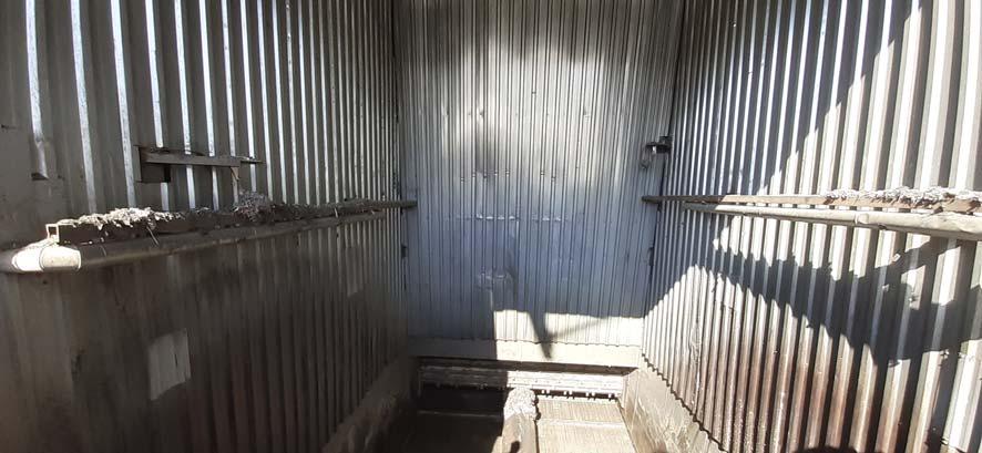
Industrial fi res and explosions can occur in many manufacturing processes when fi ne particulates, dispersed in air, are subjected to an ignition source within a contained environment – for example a duct, vessel, or collector. Ignition can be generated by many different factors, including hot surfaces, burning embers, fl ames, welding, spontaneous combustion, friction or uncontrolled electrostatic discharges. These ignition sources can be minimised or eliminated by a combination of effective engineering controls, safety management and operator awareness, but in many cases, the explosion risk is ever present and therefore techniques to mitigate the potentially catastrophic effects must be employed. It was against this backdrop that a major cement manufacturer located in the western part of Turkey recently made a multi-million euro investment in a system to allow the use of alternative, RDF and related Tyre Derived Fuel (TDF) in its process to reduce its operating costs and improve its carbon footprint. In order to achieve the maximum benefi ts from the company’s reduction targets, the system consisted of several elements, including an RDF preparation plant and semi-closed material storage warehouse, as well as RDF and TDF transportation systems. Another key consideration for the company was the fl exibility of producing its own RDF as well as utilising third party supplied TDF and RDF within its process. The RDF preparation process included the following items: material acceptance pit, front-end loader fed open top primary shredder, metal separation, air-material separation, and a connected secondary shredder where all material transport between processes was to be carried out using closed conveyors. Additionally, an externally located dust collector was to be used for dedusting of the process. RDF fuel prepared at the plant was then to be kept in a storage warehouse where the material was to be fed to the cement kiln using a series of conveyors and chutes.
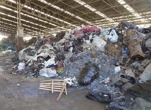
Various types of raw material used for the preparation of refuse derived fuel.
Various types of raw material used for preparation of Refuse Derived Fuel (left) and Refuse Derived Fuel material storage area (right).
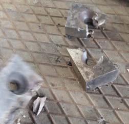
Broken shredder knives – a potential ignition source inside primary and secondary shredders. The challenge
At the outset, the company’s Operations and Health and Safety Group decided to only use solid wastes such as shredded tyres, paper/packaging wastes, oil/solvent contaminated textiles, dried sludge, and plastic as its alternative fuel source. Due to their variability, the explosibility and ignitability hazards of these materials are not well known and are diffi cult to quantify.
A data and literature review conducted on the various materials that can potentially be introduced to the system indicated that such material may become easy to ignite, especially if mixed with solvent wastes. Furthermore, explosion risks are also created by fi bres and dusts suspended inside the enclosed process equipment such as shredder enclosures and chutes. Additional risks from the unintentional inclusion of discarded aerosol cans to the shredding system were identifi ed; these could
create defl agration or fl ash fi res, which could in turn trigger secondary ignitions or defl agrations inside connected equipment. Another potential hazard identifi ed by the company was that the prepared RDF material may have a tendency to self-heat and ignite spontaneously, potentially instigating fi res inside the conveying system.
Other potential ignition sources such as broken shredder knives, electrostatic ignition sources due to conveyor movement, frictional ignition sources, mechanical sparks, hot particulates and embers were also determined as possible scenarios inside the RDF preparation plant as well as the RDF/TDF transfer system.
After the company conducted a comprehensive risk assessment, they concluded that explosion/fi re prevention and explosion protection measures would be necessary to minimise the fi re and explosion risks within their RDF and TDF handling processes. In order to meet strict safety standards and local regulations, they looked for potential specialist vendors of ATEX certifi ed systems that would be reliable and robust for use in such harsh environments. ATEX is the umbrella name given to two European Union Directives for controlling explosive atmospheres, and IEP Technologies was eventually selected to provide a complete explosion prevention and protection solution. IEP Technologies has over 60 years of expertise in explosion protection and offers leading solutions to a worldwide client base, assisting with all stages of the selection process, from materials testing, active and passive explosion protection systems, spark detection and extinguishing, and ongoing service and support.
Shredder explosion protection and prevention system. Spark detection and extinguishment on the shredder inlet and outlet chutes are shown. Explosion suppressors (red cylinders) providing explosion isolation The solution
can also be seen. The shredder explosion relief vent is After an initial site visit to study the located on the opposite end (not shown). process conditions, equipment layout and risk reduction targets,
Table 1. The specifi c protection solutions recommended for the alternative fuel IEP Technologies’ processing and transport systems. Engineering Team designed and proposed
Process Protection recommendation both explosion protection and prevention systems
Explosion protection for primary and secondary shredders with the goal of Explosion suppression on the primary shredder outlet volume and explosion isolation on the primary shredder outlet conveyor. to meet the identifi ed company objectives minimising explosion propagation to Explosion venting on the secondary shredder and explosion and requirements, while connected equipment. isolation via suppressant barriers on the inlet and outlet offering a highly reliable conveyors feeding the shredder. ATEX certifi ed solution. The specifi c protection System consists of: solutions recommended by IEP Technologies for the Triple IR fl ame detection and extinguishment on the RDF/TDF alternative fuel processing acceptance pit to detect and extinguish any fl ash fi res inside and transport systems are the pit due to aerosol can fi res or material fi res inside the summarised in Table 1. transfer pit. The explosion protection
Spark/hot particle/fl ame detection and system installed on extinguishment on the shredder systems. Hot particle/spark detection and extinguishment on the primary the RDF preparation shredder discharge chute. process included explosion detection Hot particle/spark detection and extinguishment on the secondary shredder feed and discharge chutes. using IEP Technologies’ ATEX certifi ed SmartDS Spark detection and extinguishment on the dedusting duct. and IR (Infra-Red) fl ame detectors along with
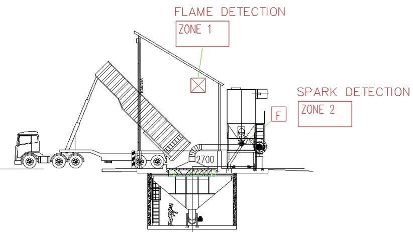
Spark/hot particle detection and extinguishment on RDF/TDF transfer conveyors. Detectors located on the drop chutes to detect sparks, hot particles or embers inside the high fl ow conveyor system. The system consists of detection and extinguishment on various drop chutes over fi ve different protection zones. E-HRD suppressors, designed to provide high speed detection of incipient explosions
coupled with a high degree of false-alarm immunity. Additionally, IEP Technologies’ explosion relief vent panels were used on the secondary shredder feed chute volume with a vent duct directing the products of any explosion to a safe location outside. SmartDS explosion detection technology uses a ‘rate of rise’ principle to determine explosion pressure at a very early stage, able to differentiate between normal process pressure fl uctuations and defl agration events. When used together with the IR fl ame detection, SmartDS reduces suppressor isolation distances while increasing overall detection reliability. The detection and suppression systems are linked back to an EX8000 controller which provides monitoring and control to each process/zone and a comprehensive event log.
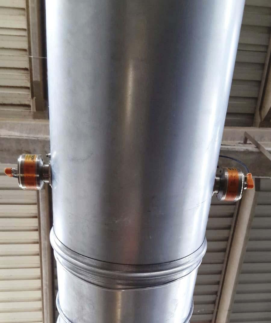
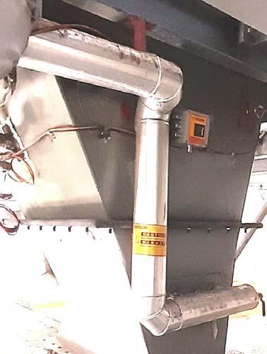
The Spark Detection and Extinguishment System utilised a patented ATEXON V300EX spark/hot particle detection system which is a wide spectrum fl ush mounted detector along with extra wide fi eld of view. This detection system is mounted without the need for welding fl anges and is fl ush mounted on the surface of ATEXON V300EX detectors mounted on the the equipment. The V300EX Spark Detector has dedusting duct. full 180° viewing angle which makes it possible to cover the whole cross-sectional area of the protection zone. Another important requirement in RDF handling processes is the ability to detect not only sparks but also hot particles. If the temperature of the particle is less than 500ºC it does not emit visible radiation and is not considered to be a ‘spark’. However, these hot particles are RDF/TDF transportation system/acceptance pit. Triple IR (IR3) fl ame viable ignition sources for biomass and RDF transfer detectors are located on opposite corners looking inside the pit while extinguishers located on the two sides provide wide angle coverage. systems – for example, where thick material layers exist in the conveyers and silos. IEP Technologies therefore utilised its V300EX detector, which has the ability to detect hot particles with temperatures as low as 300ºC. The high-pressure extinguishing systems installed in the process are activated by fast response solenoids with spring loaded nozzle mechanisms operating at pressures of 7 – 9 bar. The nozzle systems used in the design Sample layout of the detectors on the material acceptance pit and on are specifi c for high speed dedusting pipe.
Typical spark detection and extinguishment locations on a chute for most reliable operation.
dust transportation ducts and transfer chutes between belt conveyors. Due to the minimal protrusion into the duct, they avoid wear from abrasion, while the high-pressure water spray prevents product from clogging the nozzle. The extinguishing system also monitors the water temperature, water fl ow and ball-valve position, increasing overall system reliability. When a single spark is detected, the extinguisher is actuated for roughly one second to extinguish the hot particle or ember without stopping the process, however if multiple consecutive sparks are detected within a short period, the system engages the extinguishment function while also activating alarm relays to shut down the process.
Conclusion
As the global cement industry continues to use more and more RDF/TDF type alternative fuels, the risks from explosions and fi res will continue to increase unless suitable preventative and/or protective measures are employed. As illustrated in this article, thorough study of the process, equipment and conditions as well as appropriate hazard assessments are required in order to identify all high-risk areas before deciding on the most appropriate protection measures to take. Having on-site reviews prior to decision making, as well as providing necessary engineering and onsite support during installation is crucial in successful implementation of an explosion protection and prevention solutions. Following on from initial installation and commissioning, annual site visits are planned for customer training and periodic system maintenance of both spark detection and explosion protection systems by IEP Technologies’ Field Service Team in Turkey. With both systems now up and running, the company’s Operations Manager praised IEP’s technical team for their involvement and competence during every stage of the project from start to fi nish.
RDF conveyor discharge chute spark/hot particle detection and extinguishment. About the author
Emre Ergun is the Managing Director of IEP Technologies Turkey. He has 20 years of experience in the industrial explosion protection fi eld with focus on product development, R&D, application engineering, standards development and business development. He holds a BS in Chemical Engineering from Middle East Technical University, Ankara, an MS in Engineering Management from Northeastern University Graduate School of Engineering, Boston, and an MA and MBA from Babson College, F.W. Olin Graduate School of Business. Emre is a certifi ed safety auditor by the National Association of Safety Professionals, NASP.
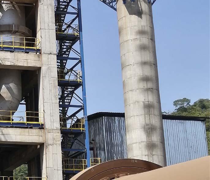
Luiz Felipe de Pinho and Roberto Campos, Dynamis, discuss the company’s role in the design and supply of equipment for Cementos Argos’ Rio Claro calcined clay activation plant and explain how clay activation technology could allow for a more sustainable and competitive method of cement production.

CLAYING IT ALL ON THE LINE
ver the years, companies have been searching for business models that can bind together both development and sustainability. New environmental regulations and commitments to society have driven companies to lower their carbon footprint and minimise the usage of fossil fuels and electric power. On the other hand, in a more global and competitive world, markets force companies to lower their prices and cut production costs.
D-Gasifi er attached to the kiln hood. A solution for sustainability
In the cement industry, one of the best solutions for increasing both sustainability and competitiveness is to substitute clinker with pozzolanic-like materials, such as artifi cial pozzolan, natural pozzolan, fl y ash and blast furnace slag. However, the application of these materials may be limited by important factors.
Natural pozzolan availability is restricted to geographic regions with volcanic soils, while slag demands high electricity consumption for drying/grinding, and fl y ash availability is decreasing rapidly due to the phasing out of coal power plants, making this material more expensive and increasingly unavailable. On the other hand, there is a large availability of clay with thermal activation capacity worldwide, allowing cement producers to industrially manufacture a very high-quality material without the necessity of raw grinding, whilst having control over its production capacity and clay properties. Artifi cial pozzolan therefore has great potential for supplementary cementitious material.
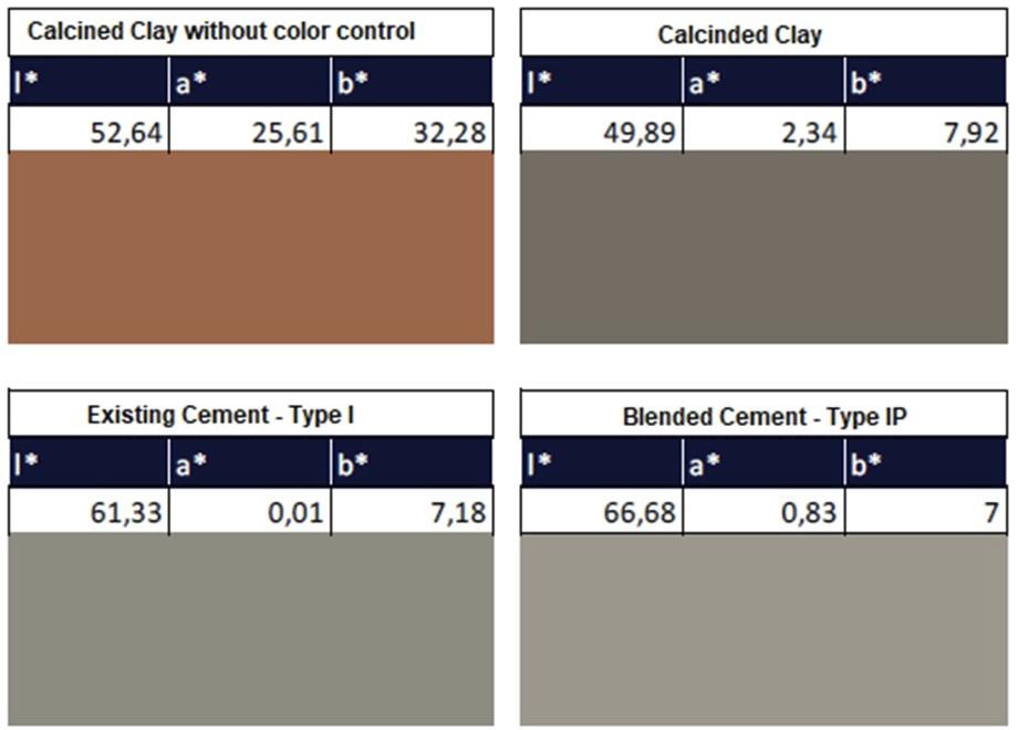
Colour comparison between calcined clay with and without colour control and a colour comparison between regular cement and cement blended with calcined clays.
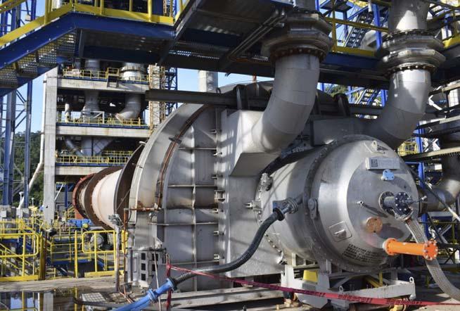
D-HotGas hot gas generator connected to the Flash Dryer (left). D-Gasifi er Combustion Chamber of the hot gas generator and its BMS system (right). Real applications with artifi cial pozzolan
Artifi cial pozzolan is produced by an increasing number of cement manufacturers, and Dynamis is playing a major role in this fi eld with the design and equipment supply for several clay activation plants, such as Cementos Argos’ Rio Claro 1500 tpd line, the largest calcined clay kiln in the world.
In April 2019, Cementos Argos’ new calcined clay production plant started its operation. Located at the Rio Claro site in Colombia, this line was designed using the D-Pozzolan® technology, to take on challenges such as the production of high-grade pozzolan, starting from low-grade clay, and a decommissioned kiln. Other than the pyroprocessing, Dynamis took part in project
development activities in close partnership with Argos. These activities started with initial laboratory tests, that developed into an engineering project and culminated in the equipment supply and technical assistance during erection and start-up.
The most impressive aspect of this plant is its colour changing technology. It is interesting to see the reddish clay being fed in to the dryer, changing its colour inside the rotary kiln and fi nally leaving the cooler as grey calcined clay. This is part of the D-Pozzolan technology, a complete solution carefully designed by Dynamis to meet the specifi c needs of the clay calcination process. The grey colour of the calcined clay allows high substitution rates and important reductions in the clinker to cement ratio, as well as a reduction in cost and also in the CO2 footprint of the cement produced.
The quarry is connected to the industrial plant by trucks. The raw clay received at the plant is processed by deagglomerators which are responsible for obtaining the ideal clay grain sizes for the D-FDryer (Dynamis’ fl ash drying system). Inside the dryer, the solid particles are dragged by the hot gas stream, making it possible to achieve high heat and mass transfer coeffi cients in a relatively small space and with a small footprint. The preheated and dried material dragged by the gas stream is separated from the fl ue gases by a set of cyclones.
The hot gas for material drying comes from the kiln and is complemented by the D-HotGas, the Dynamis hot gas generator designed for 100% coal or petcoke. It is important to have the optimum gas fl ow in the drying system to enable clay particles to drag. Furthermore, the hot gas generator complements the thermal load for material drying.
The dry clay collected by the cyclones is fed to the rotary kiln. At the feeding chute, the clay is mixed with coal particles of controlled grain sizes, which act as a reducing agent inside the kiln.
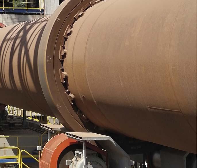
The rotary drums (kiln and cooler) used in this project came from deactivated units and were adapted by Dynamis. This utilisation of decommissioned equipment was a premise established by Argos.
Dynamis D-Pozzolan technology, with the application of a D-Gasifi er that operates with solid fuel (coal or petcoke), provides solid control over temperature and oxygen content throughout the kiln, which are fundamental conditions for obtaining thermally activated clay, for assuring its colour change and for achieving the desired quality.
The product from the kiln is forwarded to a rotary cooler. As for the kiln and the dryer,
it is important that material cooling is carried out in a controlled atmosphere so that the grey colour achieved in the previous stages does not reverse. Thus, the airfl ow for cooling is minimised. Lifters installed inside the cooler maximise the heat exchange coeffi cients between the air and the material. However, the cooling process must be complemented with water. Dynamis installed water channels over the cooler, promoting the formation of a water fi lm on the shell. Thus, the low temperature of the calcined clay at the cooler outlet is achieved through the airfl ow inside the rotary drum and the fl ow of water outside the cooler shell. Finally, if any unexpected conditions occur and the calcined clay temperature exceeds the maximum set value, emergency lances spray water inside the cooler.
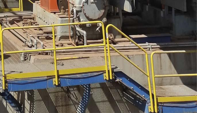
View of the water channels above the rotary cooler. Summary
Dynamis is constantly searching and investing in improvements in calcined clay production technology. There are many opportunities for innovation, such as the fl ash technologies for clay drying and calcining developed by Dynamis. Argos’ Rio Claro line appears as an important landmark in the development of clay activation technology and of a more sustainable and competitive method of cement production.
About the author
Luiz Felipe de Pinho is the CEO of Dynamis. He earned his Bachelor’s Degree in Mechanical Engineering at the University of Sao Paulo in 1995. Luiz has over 25 years of professional experience in cement and lime, mining, metallurgy, chemical, agribusiness, and food industries.
Roberto Campos is an engineer at Dynamis, and holds a Bachelor’s Degree in Mechanical Engineering from the University of Sao Paulo.


MAKING GRATE STRIDES

Valentina Bordei and Valentina Bordei and Viktor Penner, thyssenkrupp, Viktor Penner, thyssenkrupp, show how an improved static show how an improved static grate design could enhance grate design could enhance cement plant performance cement plant performance with a more stable operation, with a more stable operation, higher equipment availability, higher equipment availability, lower fuel consumption, and lower fuel consumption, and increased clinker production. increased clinker production.


The static grate plays an important role he static grate plays an important role in the overall cooler performance, in the overall cooler performance, infl uencing key performance indicators infl uencing key performance indicators such as equipment availability and the such as equipment availability and the overall energy effi ciency of the kiln line. From overall energy effi ciency of the kiln line. From its fi rst introduction decades ago, its design its fi rst introduction decades ago, its design has evolved to accommodate the knowledge has evolved to accommodate the knowledge gained from practical experience. The newest gained from practical experience. The newest polysius polysius® double inclined static grate is the double inclined static grate is the result of R&D efforts and feedback from result of R&D efforts and feedback from hundreds of coolers in operation. Its main hundreds of coolers in operation. Its main features include minimal operation disturbances features include minimal operation disturbances and maximum heat recovery. and maximum heat recovery.


Static grate function and design
The static grate fulfi ls several key functions: Quick initial cooling in order to ‘freeze’ the clinker phases and stabilise the alite content (C3S), therefore ensuring high product quality. Enhancing the heat recovery to the kiln and calciner and reducing the fuel consumption of the kiln line. Spreading the material falling from the kiln uniformly over the width of the cooler grate to allow a homogeneous cooling result.
A poorly performing static grate not only increases operating costs, it can also lead to a reduction in equipment availability. Phenomena like red river formation and snowmen are the result of an interplay between material chemistry, burning conditions in the kiln and insuffi cient/slow cooling on the static grate, and they can seriously disturb the operation of the plant. The new design of the polysius static grate addresses all of these issues.
The geometry of the static grate was adapted to improve the lateral distribution of the clinker and the penetration of air in the clinker layer. By narrowing the horseshoe and extending the static grate length, the new design helps distribute the material more evenly over the grate width. It has been observed, especially in wider coolers, that air can shortcut through the lateral fi elds of the static grate, where the clinker layer is more shallow, resulting in an insuffi cient aeration of the central fi eld. This leads to inhomogeneous cooling and reduced heat recuperation. The increased length of the new design also ensures that the residence time is suffi cient to allow for vigorous heat exchange between the solids and air. The inclination of the static grate was also changed to reduce the height of the clinker dead layer. A certain so-called ‘dead layer’ of cold, stationary clinker is necessary in order to protect the aeration plates from heat damage and extend their operating life. If the dead layer is too thick, it can cause unnecessary fl ow resistance, reducing the effective aeration to the incoming hot clinker. This aeration is crucial to stop phenomena like red river from forming. The new static grate has two sections: an initial section with a steeper inclination, and a shorter one with the standard inclination angle. Together, they ensure that the aeration plates are continuously covered by a protective layer of cold clinker, but without an excessive pressure drop. The grate is also equipped with the latest design in aeration elements with a well proven spillage-free labyrinth design. The plates also have a very low pressure drop and are made of temperature-resistant steel.
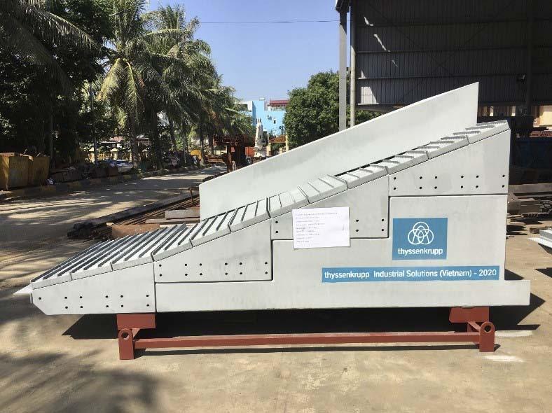
Figure 1. A section of the new static grate outside the manufacturing workshop, ready for shipment to the installation site. The grate was delivered in two fully assembled longitudinal sections.
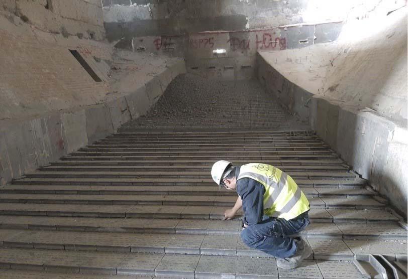
Figure 2. After mechanical installation, the refractory of the static grate was renewed to correspond to the new grate geometry. The fi rst installation: BinhPhouc cement plant – Vicem Hatien 1 Company, Vietnam
The polysius plant consisting of a polysius kiln, double-stranded DOPOL preheater and REPOL cooler was commissioned in 2008
with a design capacity of 5500 tpd. Before the upgrade, the kiln line was operating with a remarkable clinker production capacity of ~6200 tpd, but with an increased heat consumption. A closer investigation coupled with a kiln audit performed by thyssenkrupp specialists from Vietnam and Germany helped to identify the root cause of the issue, and suggested opportunities for improvement. It was determined that the relatively low recuperation effi ciency of the cooler was the main culprit for the increased heat consumption. The plant burns local anthracite coal with a low volatile matter content, which requires high temperatures (above 900°C) for ignition and complete combustion. Therefore, a high tertiary air temperature is required to improve burnout and signifi cantly reduce fuel consumption. Furthermore, the plant was suffering from reduced plant productivity due to red river formations with a negative impact towards clinker quality as well as equipment availability.
Since the overall mechanical condition, as well as the original hydraulic system of the REPOL cooler were still in a very good condition, a complete cooler conversion did not make economic sense. thyssenkrupp set its focus on boosting the effi ciency of the recuperation zone with a small and fast, but at the same time, highly effective upgrade of the static grate. This is where the newly developed polysius static grate was introduced.
The upgrade
The upgrade of the static grate was realised within ten days, during the normal yearly maintenance shutdown of the kiln. Besides removing the old grate and installing the new one, a few additional adjustments were required. Due to the increased length of the new static grate, the fi rst three rows of the REPOL moving grate needed to be removed. Underneath, the discharge hoppers for the inlet section were sealed off as they were not required anymore, thanks to the new spillage-free aeration elements. The aeration chamber compartments were also adjusted in size to fi t the new high pressure process fans. Finally, after the mechanical installation was complete, the refractory was renewed in the conversion area to fi t the new horseshoe design, including the temperature resistant shock blower nozzles (Figure 2).
The improvement in operation was obvious immediately after restarting the kiln line. After a smooth commissioning, an increase in the tertiary air temperature of more than 100°C was measured, which allowed the calciner to reach the optimum temperature level required for the combustion of the anthracite coal fuel. As expected, the red rivers in the cooler had disappeared. A process expert from the Hanoi offi ce stayed on site after commissioning to support the customer to maximise the plant performance. Because of the higher recuperation effi ciency, new set points for the operation of the kiln system needed to be worked out. For the cooler, the control loops and the overall aeration profi le were adapted to the new operating point. The fl ame shape was modifi ed using the easily adjustable nozzles of the existing polfl ame VN to enhance combustion in the sintering zone. A shorter, more compact fl ame leads to better burnout with diffi cult fuels.
While the poor cooling on the static grate had in the past led to repeated formation of red rivers, limiting the overall clinker bed height to 500 – 600 mm, with the new improved cooling in the inlet section, it was possible to raise the clinker bed height on the moving grate up to 800 mm. The resulting increase in residence time led in turn to a decrease in the clinker end temperature below 80°C (signifi cantly below 65°C+ ambient). The benefi ts of the upgrade and process optimisation carried over to the preheater tower as well. While the secondary and tertiary air temperatures increased, the preheater exhaust temperature and volume fl ow decreased, providing more capacity for the ID fan. This in turn allowed the kiln system to run with an increased and stable clinker production capacity of around 6300 tpd.
Conclusion
Overall the result of this upgrade was a success. The return on investment for the customer is manifold: A more stable operation, higher equipment availability, lower fuel consumption, and higher clinker production. In this case, what is good for the wallet also benefi ts the environment, since the reduced fossil fuel consumption and improved energy effi ciency simultaneously reduces CO2 emissions. thyssenkrupp will also support the environmentally-conscious customer on their journey to further reduce the environmental footprint of the plant.
About the authors
Valentina Bordei is a Process Engineer with fi ve years of experience in the cement industry. She has been working in different capacities for thyssenkrupp, including the research and development of new emissions reduction technologies. Currently she is the Product Manager for the clinker cooler polytrack® and the polfl ame® burner.
Viktor Penner is a Mechanical Engineer with more than 10 years of experience in the cement industry. He has been working in different capacities for thyssenkrupp, including project engineering for pyroprocessing in Germany. Currently he is the Head of Sales, responsible for Pyro Technology in South-East-Asia.
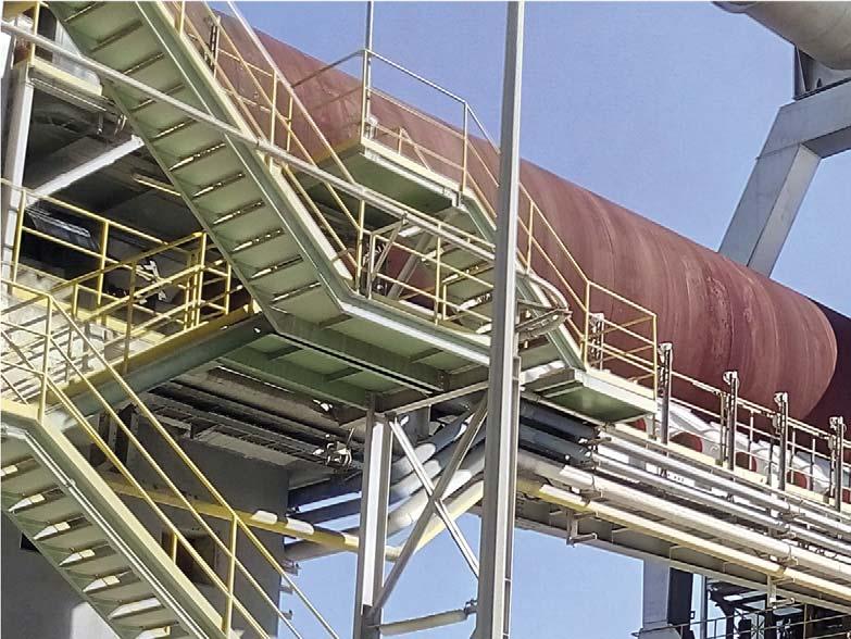
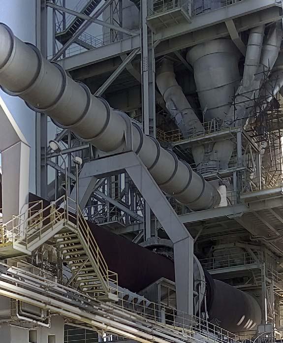
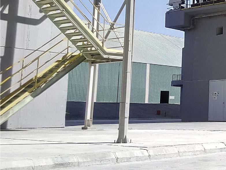
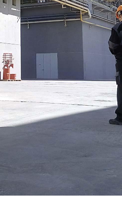
Paweł Kędzior, Havec Engineering Co., outlines how Hot Kiln Alignment can be employed by cement producers as an effective method of preventive maintenance.
PAYING ATTENTION PAYING ATTENTION TO PREVENTION TO PREVENTION

One of the main goals of any cement plant is to ensure the continuity of production and maximise profi ts by minimising costs. To achieve this goal, it is necessary to keep production equipment in perfect condition throughout its entire service life. A Preventive Maintenance Strategy helps with this aim. Its main role is to detect the causes of potential problems long before malfunction. When existing problems are visually obvious, it is often too late. Preventive maintenance with the use of analytical tools can help eliminate the causes of damage.
The heart of every cement plant is the rotary kiln. Maintaining its proper condition is extremely diffi cult and becomes one of the main challenges involved in ensuring the continuity of production. 99% of all problems related to the operation of the kiln are linked to: Misalignment of the kiln axis Axial balance Kiln shell crank Kiln shell ovality

All of these problems are diagnosable using Hot Kiln Alignment.

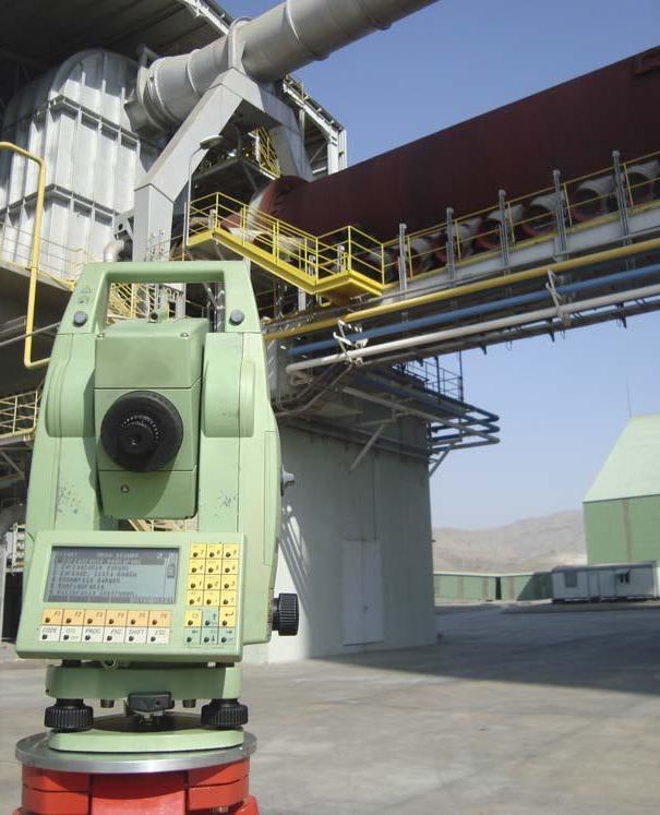
Highly accurate measuring equipment. A new approach
The rotary kiln is one of the most demanding pieces of equipment from a maintenance and operation point of view. It is a kind of a dynamic reactor, with many parameters affecting it chemically, mechanically and electrically at the same time.
Cement producers have to act dynamically, like the kiln itself, in order to prevent changes in the above-mentioned conditions from affecting its main components, such as: tyres, rollers, shell, brick lining, bearings etc. Cement producers must therefore rely on their actions to maximise the lifetime of the kiln and achieve the desired working conditions. To achieve a realistic view of the kiln’s operation conditions, the following possible inspection methods can be used: Surveying (use of advanced technology, knowledge, experience, accurate and advanced equipment) Vibration analysis Thermography Defectoscopy Mechanical analysis
As a part of a Preventive Maintenance Strategy, periodic alignment of the rotary kiln helps to locate and eliminate operational problems at a very early stage. Instead of costly repairs or damage, with the help of precision measurements and analysis, it is possible to precisely identify and eliminate the causes of kiln damage. If only outcomes are being dealt with, it is highly probable that problems will re-appear and that damages will multiply.
Experiencing unplanned kiln stoppage, frequent replacement of kiln components, and excessive wear, is a product of an incorrect maintenance strategy. A clearer and more focused picture of real equipment conditions is needed.
The main purpose of Hot Kiln Alignment is to conduct mechanical inspection and to specify activities (adjustments, exchanges, repairs, modifi cations, etc.) which should be performed to attain and maintain high effectiveness of the rotary kiln’s operation.
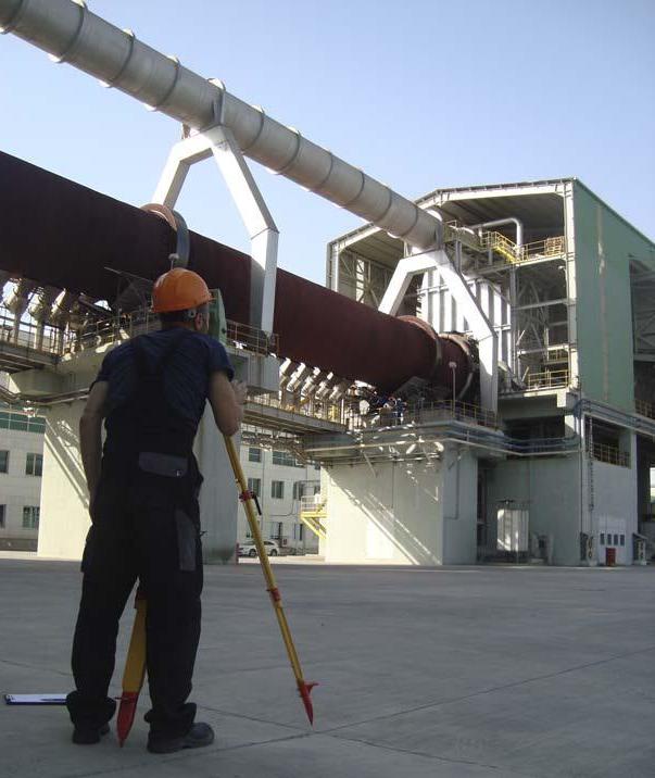
Misalignment of kiln axis
Precise measurements of kiln axis and roller position.
Preventive maintenance routine.
Achieving the correct alignment of the kiln axis is particularly important from a load distribution point of view. Deviation of the kiln axis from its optimal shape has a negative impact on supports, tyres and the kiln shell. The axis of the kiln is not constant during operation, especially in a vertical plane. Changes in temperature distribution on the kiln shell, can cause the axis position to be unstable and this change in position
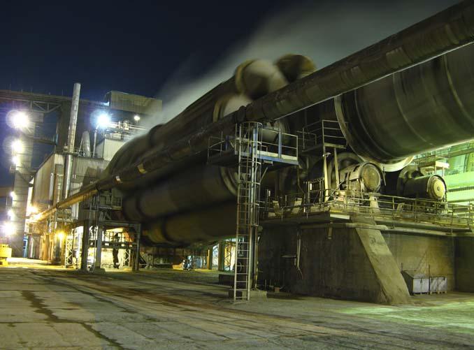
causes different load distribution on rollers and support roller bearings. It is important therefore to maintain the correct kiln shell temperature during operation.
Correct kiln axis geometry is responsible for the even distribution of weight, coating, brick lining, and the components for all the supports. Alignment of the kiln in a vertical plane ensures proper load on each individual support, but alignment in the horizontal plane ensures equal distribution on left and right rollers.
Consequently, any changes in the geometry of the kiln axis over time cause changes in the load distribution and thereby changes the longitudinal bending stress distribution in the kiln shell. Such load changes are closely related to the kiln stiffness (the relation between the diameter, shell thickness and distance between support etc.) and may involve a risk of failure or reduced service life of the kiln components. Frequent checks of the kiln axis position are recommended as an integral part of the kiln maintenance.
To properly assess the impact of the axis geometry on the kiln operation, a detailed knowledge of the mechanical stiffness of the kiln shell and the current status of components on the supports is needed. The mechanical condition of the kiln must be carefully examined. In addition, the position of kiln axis must be measured during normal operation in hot conditions.
With the help of Hot Kiln Alignment procedures, determining the optimal kiln axis alignment can allow problems to be located and eliminated. Through frequent monitoring of this parameter, even with very small adjustment steps, signifi cant kiln operation improvements can be observed and kept under control.
Kiln shell ovality
Ovality is a parameter which describes how well a kiln shell is able to support the refractory. Rotary kiln refractory brick linings depend on the principal of the continuous arch to stay in place. Naturally any forces acting on that arch, such as fl exing of the kiln shell, will act to weaken the mechanical stability of the arch.
Axial balance
The axial balance of the kiln is dependent on many factors, including: geometrical position of support rollers, both in horizontal (skew of rollers) and vertical planes (inclinations), mechanical wear of running surfaces of tyres and rollers, and hydraulic thrust unit effi ciency. Each of these elements generates an axial force, acting on the kiln in a particular direction and with a specifi ed value. In an ideal situation, both the support rollers and tyre surfaces should be cylindrical and their axes parallel to the main kiln axis. In practice, however, especially after many years of operation of each individual component, such a situation is extremely rare. The running surfaces wear out and the axes of the support rollers experience a geometrical deviation, causing further damage to the rotary kiln components.
Exceeded tolerances of rollers skewing and rapid wear of support roller bearings (in particular thrust blocks), where increased axial force creates higher pressure, results in an increase in temperature of the bearing. Additionally, the incorrect geometrical position of the rollers causes a loss of contact between running surfaces of tyres and rollers so that wear of these surfaces increases. Axial forces generated by incorrect rollers skewing and inclination is transferred directly to the other components. Often the damage or premature mechanical wear appears on the sides of tyre and stop-block surfaces. In the same way, the axial forces are directly transmitted to the thrust roller resulting in faster component wear.
Incorrect kiln balance (e.g., a kiln operating in one axial position for too long) also causes accelerated and uneven mechanical wear, both for the running surfaces of support rollers and kiln drive components (pinion and girth gear).
With the help of the Hot Kiln Alignment procedures, all axial force generators can be easily determined. By knowing the actual geometrical position and mechanical conditions of components, plant maintenance crew can achieve optimum kiln balance and minimise the wear of critical components.
Comprehensive inspection of the rotary kiln.
Correct alignment improves brick lining lifetime.
It is not uncommon, therefore, for refractory to fall out a short time after installation if excessive fl exing of the kiln shell exists. Ovality measurement is a method for determining how much a kiln shell fl exes.
Ovality measurement and analysis is a description of mechanical stability of the refractory. All kiln operators need to be aware of the behaviour of their kiln under its various conditions. Cyclical measurements provide a history of conditions which can be used to analyse very important refractory problems. Excessive ovality will damage the refractory lining, typically, with scattered ‘spallings’ and single brick fall-outs among otherwise undamaged areas.
Kiln shell crank
If the kiln cross-section centreline does not coincide with its axis of rotation, the kiln is said to have a crank, which in fact means that the support loads change cyclically during the rotation of the kiln. Crank in the shell is very dangerous because it can be accompanied by rotating extra loads. Additionally, crank is invisible until contact between the tyre and support roller, eventually, ceases. Kiln shell crank can by described by two parameters linked together – local deformation and radial run-out (eccentricity).
Local deformation of the kiln shell is the shape deviation from circularity and has a negative effect on brick lining inside the kiln, shortening its lifetime. It is essential from a maintenance point of view to monitor the lining condition at every kiln renovation stoppage. When the loss of lining is observed repeatedly in the same place, a shell segment replacement should be taken into consideration.
Kiln shell radial run-out has a negative impact on most kiln components e.g., too much or uneven pressure on shafts of rollers, running surfaces of tyres and rollers, radial run-out of inlet or outlet sealing, root clearance values changing at the girth gear station, increased axial tyre thrust (excessive mechanical wear of tyre side surface and stop-blocks), and uneven load distribution between tyres and rollers as a result of ‘wobbling’ etc. Therefore, it is extremely important to control this parameter through the continuous monitoring of temperature around the shell circumference (especially shell segments located close to tyres) and conduct the correct procedures during heating (e.g., after kiln stoppage), and cooling of the kiln.
Exchange of key components
Knowledge of the real mechanical status of the rotary kiln allows kiln operators to facilitate the planning process of key component exchange. A comprehensive inspection of the kiln will highlight priority repair actions. Such information is crucial when forming and planning budgets. Hot Kiln Alignment measurements and analysis can help identify wear levels for almost all of the important kiln components and allow operators to make the decision to replace, repair or re-design.
The importance of alignment
Kilns change over time in a way that cannot be easily predicted. The limits of proper operation are so low, that even if the kiln is working well it needs to be monitored.
Statistical research based on operational mechanical wear factors shows that Hot Kiln Alignment intervals should be set to two years, and this is calculated and estimated for a kiln that has no obvious operational and mechanical problems.
Hot Kiln Alignment is not only a measurement. It is, above all, a comprehensive mechanical inspection, and produces very advanced analyses, allowing even the most complex problems to be observed within the operation of the rotary kiln. It is also a perfect diagnostic tool allowing for detailed planning of activities, repairs and replacements during a yearly overhaul.
Hot Kiln Alignment provides plant personnel with invaluable knowledge about the conditions of the equipment. This type of condition monitoring tool is an investment, preventing unplanned stoppages of the kiln or the need for renovation or replacement jobs.
Potential problems can be detected at a very early stage and removed at a minimal cost – this is the Preventive Maintenance Strategy.
About the author
Supervision over roller adjustment.
Paweł Kędzior is the CEO of HAVEC Engineering, a company providing international services focused on rotary kilns for maintenance and operation. Paweł is an engineer with much experience in mechanical, technological, and engineering sectors and has an MSc. diploma in surveying sciences in the fi eld of Industrial Precision Measurements. Paweł is also a designer of innovative early-warning monitoring systems dedicated to rotary equipment for the industrial sector, and mechanical challenges in rotary kiln maintenance.


