10 minute read
Tech feature: Fuel system focus

from Auto Channel 45
by Via Media

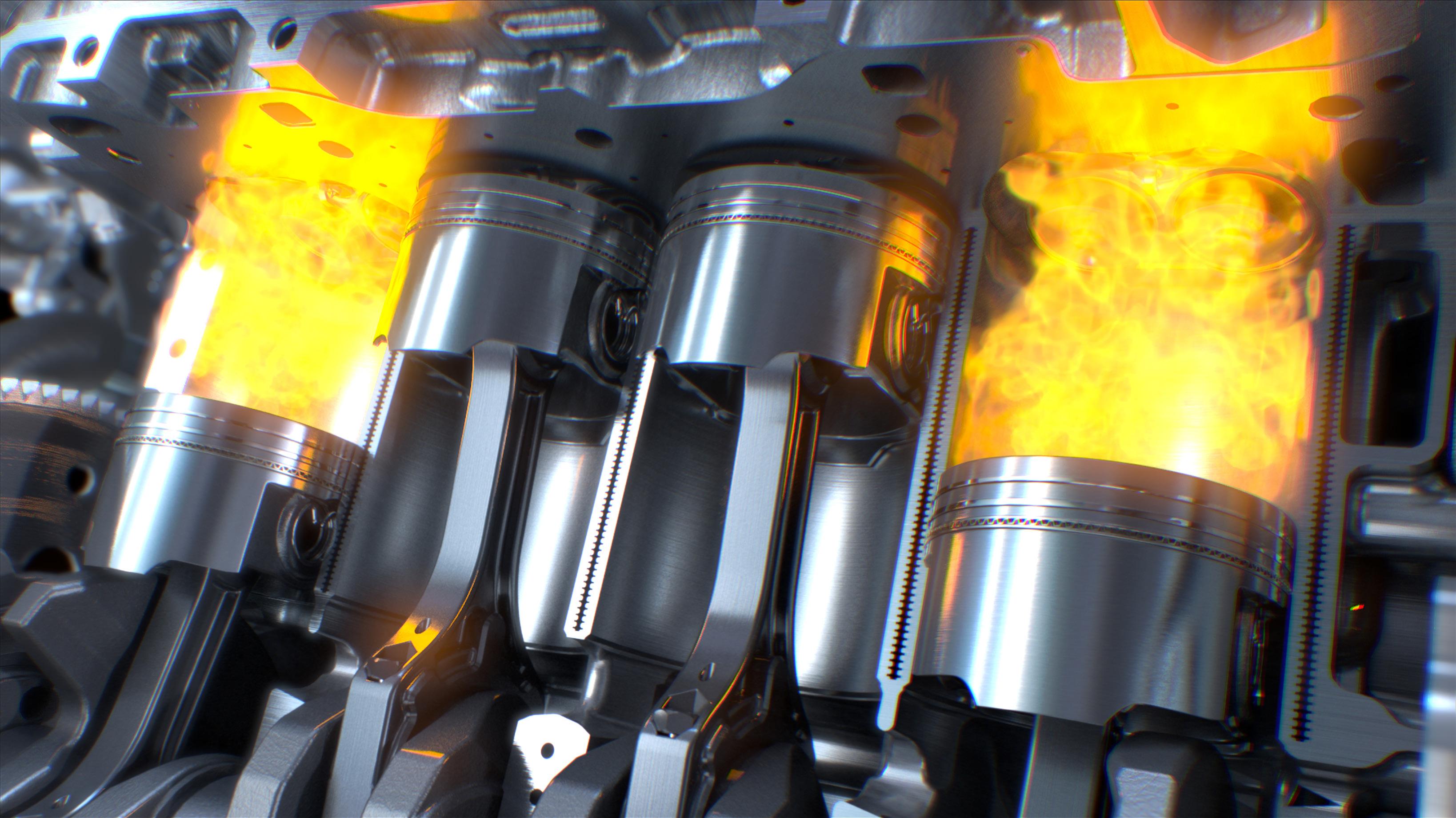
The magic mixture
EVERY COMPONENT IN THE FUEL SYSTEM, FROM TANK TO INJECTOR, HAS A ROLE TO PLAY IN FEEDING THE ENGINE THE RIGHT MIX
Advertisement
The drive to increase overall efficiency has powered innovation and development in vehicles and aircraft almost since the first inventions. Now rising fuel costs, and a greater awareness of our impact on the environment, place even greater emphasis on this goal both for consumers and regulators.
While the current crunch on oil supplies is accelerating the switch to electric power among consumers and car makers, the drive to make the most of conventional power plants and to reduce emissions remains fierce.
And, of course, there are many thousands of cars and utes out there running conventional fuel injection engines and, to keep them running as efficiently as possible, you need to make sure that all elements of the fuel delivery/control systems are working exactly as they should.
THE SUM OF ITS PARTS
Every component in the fuel system, from the fuel tank to the injectors, is designed to deliver the correct amount of fuel to the engine under any foreseeable circumstances. The ECM is in charge of maintaining the correct air/ fuel ratio and does so by controlling the amount of fuel injected, based on its internal programming and data received from external sensors.
The simplest way to understand how the ECM performs this task is to remember that it has no idea what is happening unless it is told. For it to figure out how much fuel to add, it has to know how much air is getting into the engine. More precisely, it needs to know how much air by weight. A stoichiometric air/fuel ratio for petrol engines is 14.7 pounds of air to every pound of fuel. So what affects the weight of the air? Altitude does, and so does temperature. Early fuel injected systems used manifold absolute pressure sensors (MAP), among others, to allow the ECM to calculate the density of the incoming air charge using the ‘speed-density’ method. Many manufacturers have switched over to mass airflow sensors (MAF). This sensor measures the mass of the air entering the engine directly. With either method, once the ECM knows how much air is going in, it can calculate how much fuel it needs to add.
It delivers that calculated amount of fuel by precisely controlling how long the fuel injectors are held open. This is the pulse width parameter identifier (PID) you see on your scan tool. Typically, a fuel injector will be held open only for a few milliseconds at idle. To put that in perspective, watch a spark jump across a plug gap for a few seconds. That takes about 1.5ms, so multiply that by two. Not much time, is it?
Once the ECM has delivered the charge and combustion has taken place, it needs to be told if the charge delivered was correct. This is where the oxygen sensors come in. Let’s stick to conventional sensors and Air-Fuel Sensors (AFS). The first functions more like a switch than a sensor, while the latter can measure what’s left over in the exhaust pipe. Both report what they see to the ECM, so it can decide whether it hit its mark or not, and if not, if it missed by too much or too little. The ECM takes that feedback and alters the next injection to compensate, then waits for the report on how it did that time. This is what techs refer to when they say a system is in ‘closed loop’. ECM trouble codes (DTCs) for system lean or system rich will set when the ECM can’t correct enough to make the sensors happy with what they are seeing.
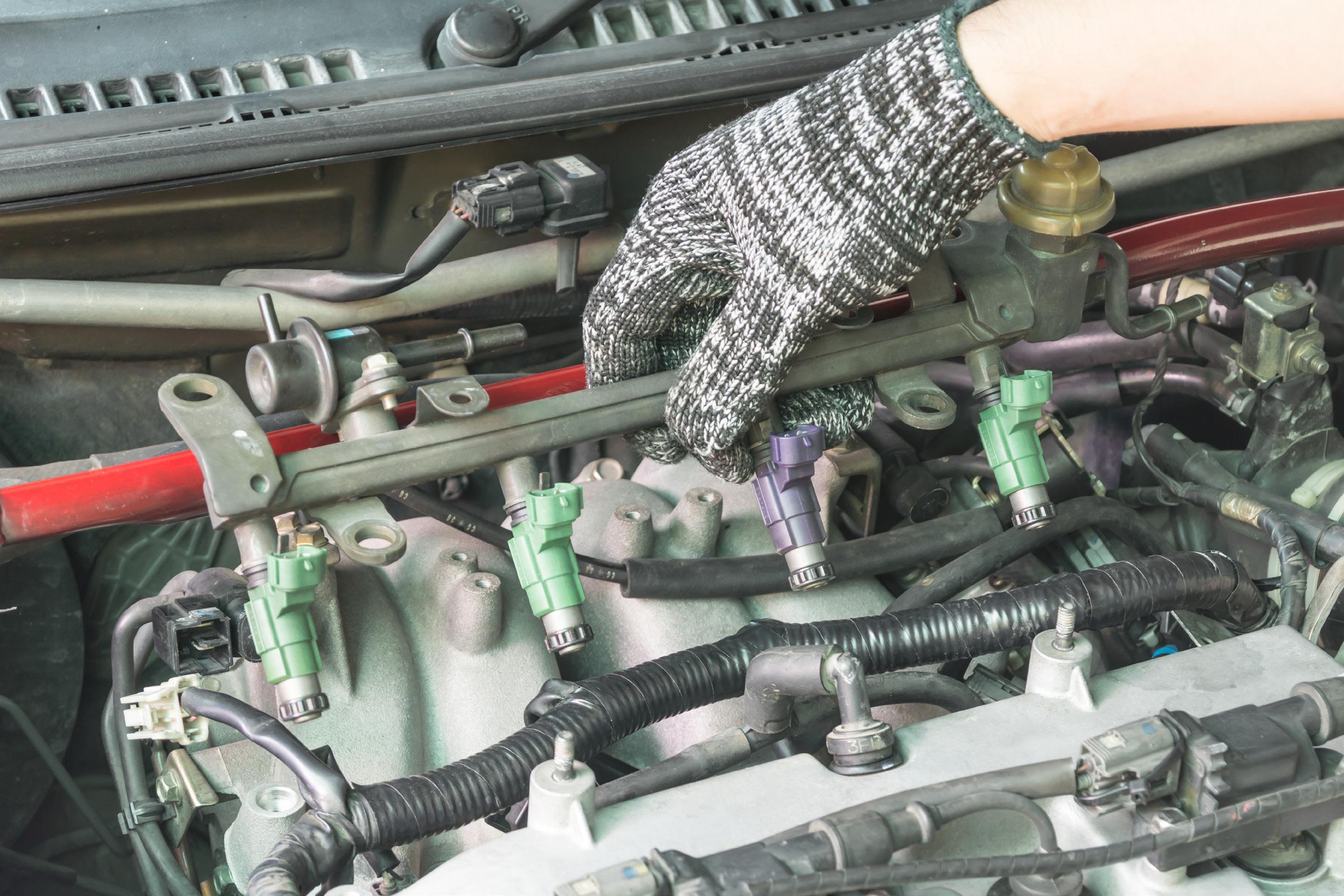
And consider this when diagnosing general drivability complaints and even some misfires — injectors are tied together by bank or by firing sequence. Currently, no injection system is able to correct an individual cylinder independently. Often, the cause of a drivability issue is found in a cylinder that is running leaner (less fuel or more air), or richer (more fuel or less air) than its companions, yet the companion cylinders are the ones exhibiting the symptoms.
For example, a leaky injector can result in a rich condition in one cylinder that is detected by that bank’s feedback sensor. The sensor faithfully reports its findings and the ECM adjusts by reducing fuel until the sensor is happy. Now the weak cylinder is getting enough fuel, but its companions are receiving too little and may even misfire as a result of this now lean condition.
BACK TO THE BEGINNING
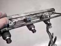
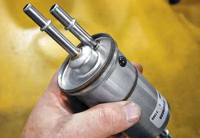
This occurs after the fuel reaches the fuel rail. The journey starts in the fuel tank. Fuel in the tank on most cars has to first pass through a filter before entering the fuel pump module. The module is a can of sorts that houses the fuel pump, and the idea is to prevent starving the pump whenever the vehicle changes direction or inclination. The pump draws what it needs from the can through another filter mounted to its inlet. The fuel then passes out of the pump and through yet another filter, before reaching the fuel rail and the injectors (many equipped with yet another filter).
Older systems had a means of regulating pressure on the fuel rail. This was thought to be needed to account for the pressure differential that existed at the injector’s tip, with one side at manifold pressure and the other at fuel line pressure. Without the correction, the amount of fuel delivered would be less when internal pressures in the intake tract increased, without a corresponding increase in fuel pressure. Engineers do not hold this concept as tightly as they once did, and most returnless systems today are equipped with fixed pressure regulation in the fuel pump module or the fuel filter itself.
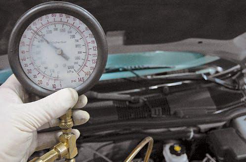
Proper fuel pressure is, of course, still an important part of a properly functioning fuel system, but often overlooked is the equally important question of fuel volume. As airflow into the engine increases, the amount of fuel required also increases and the delivery half of the fuel system has to keep up with the demand. Remember all those filters in the system? If the first is restricted, fuel flow into the pump well will be reduced and it is possible for the pump to run dry, even when it’s at the bottom of a full tank of fuel. Likewise, restrictions in the pump filter can cause pump starvation. Clogged in-line filters reduce the amount of fuel volume reaching the engine, even though your pressure tester is reading in specification. All three are good reasons to include a thorough tank cleaning whenever you replace a failed pump.


Check your service information (SI) for a volume specification, but if none is listed a general rule for static (key on, engine off) test is one quart in 30 seconds. Perform this test by disconnecting the fuel line from the rail and redirecting the fuel into a clean, graduated container. Bypass the fuel pump relay, or use the bi-directional controls on your scan tool, to run the pump. Safety first! Use eye protection and keep a fire extinguisher handy in case you splash fuel on something you shouldn’t have.
TEST
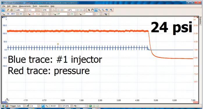
A scope is very useful here. By using a pressure transducer instead of a mechanical pressure gauge, you can use a scope to measure pressure over time and measure the pressure drop across each injector to detect one that might be leaking or clogged. Performing an injector drop test using a scan tool, or by mechanically firing each individual injector, is a time-consuming chore that is virtually eliminated by using your scope instead. All you have to do to identify the offending injector(s) is trigger off of the No. 1 cylinder’s injector, and then follow the firing order down the pattern.
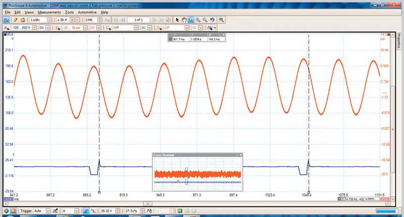
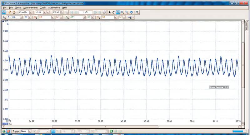
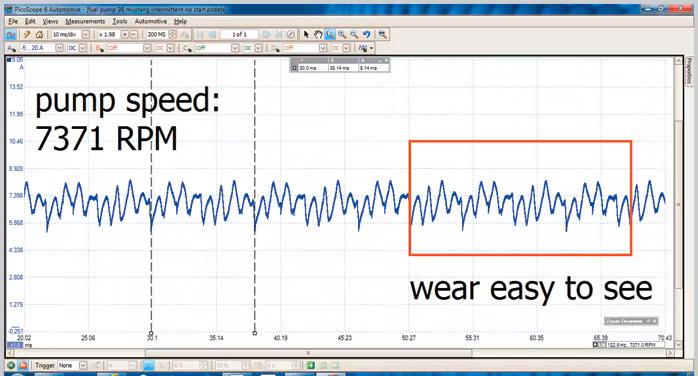
At the same time, a third channel on the scope is assigned the task of monitoring current flow through the fuel pump. This is called current ramping and is not a new technique. It has tremendous value in determining the overall health of the fuel pump by tracing the current flow through each individual commutator segment (that’s the copper strip at each end of the motor winding where the brushes contact) on the little electric motor that is the pump. Healthy pumps will have definitive peaks and valleys in the waveform, while worn pumps will have a more erratic appearance.
In addition to examining the pump for mechanical wear in the brushes and commutators, you can determine the operating speed of the pump. Most fuel pumps use eight commutator strips, but occasionally you’ll run into one that uses 10 or 12. Look carefully at your scope waveform to see if you can see the repetition in the pattern. Then place your time rulers on the peaks of the first and last segment. If your scope doesn’t calculate the RPM for you, plug the time you measured into this formula: 60,000 ÷ (time measured in milliseconds) = revolutions per minute.
Specification for pump speed is rarely listed so use 5000 to 6000 RPM with the engine running as a guide. Diagnosing a fuel delivery problem can be streamlined when you examine pump speed and the pump’s current draw together. For example, let’s say you have a no start condition and you’re troubleshooting. You stab the Schrader valve on the fuel rail with your pocket screwdriver and nothing comes out. Next, you locate the fuel pump relay and bypass it to power the pump continuously. When there is still no fuel at the rail, are you ready to condemn the pump?
NOT SO FAST
You can even leave the pressure transducer on the bench for the moment. Just grab the low amp probe and clamp it over that jumper wire you just used to bypass the relay and examine the pattern you get. As a general rule, you should see about 1 amp of current for every 10psi of pressure. Let’s say the pressure spec for the car you’re working on is 60psi. If everything is working right, the pump should draw about 6 amps.
No current flow means an open circuit and time to do a little electrical diagnosis. Low current flow means the pump isn’t working very hard and, if it’s coupled with a higher than normal RPM, odds are the pump module has run dry, or the tank is empty! But if the RPM is lower than normal, you could be dealing with a voltage drop issue somewhere in the circuit.
What if the pump current draw is high, but RPM is low? In this case, suspect a clogged fuel filter downstream of the pump. Like any motor, current draw will increase in relation to the work the pump has to do. The harder it is for the pump to spin, the more current it will demand.