
21 minute read
Original instruction manual for pewag standard lifting chains
General Description
pewag standard lifting chains are manufactured from pewag chains, connecting links and accessory parts. The main function of the lifting chain is to serve as a connection between a load to be lifted and a crane hook (fastening) that in turn, leads to the lifting and transportation of the load. The maximum working load limit as well as in most cases the associated angle of inclination for multi-leg chains, number of chain strands and the nominal diameter of the chain can be found on the tag.
pewag standard lifting chains should only be operated by properly trained persons. The longevity of the chains and a high level of safety can only be safeguarded if used correctly and as instructed which in turn should prevent accidents to persons or property. Therefore reading and understanding this instruction manual is of utmost importance before using lifting chains, but one should not neglect the importance of carrying out activities in a safe and responsible manner. The instruction manual should be easily accessible to all until such time as the machine is decommissioned. The manual undergoes constant updating, hence only the most recent version should be seen as valid which can be downloaded from www.pewag.com
Intended Use
Intended application: fastening and lifting and/or transporting loads. Detailed information on the intended use can be found in the corresponding sections on the following pages.
Working load limit: the maximum load capacity (weight) of the lifting chain depends on the chain dimensions (d), the number of chain strands, the angle of inclination (β), the sling configuration – see load capacity table. The maximum load capacity can also be taken from the marking (stamping) on the tag, but only when it’s intended use is implemented correctly.
Application Temperature: Detailed information on the application temperature can be found in the corresponding sections on the following pages.
Angle of Inclination: The angle of inclination is the angle between the chain lane and an imaginary vertical line. If multi-leg chains are used, the angle of inclination must lie within the specified range of 0-45° and/or 45-60° and should not differ from each other by more than 15°. Angles of inclination under 15° should be avoided.
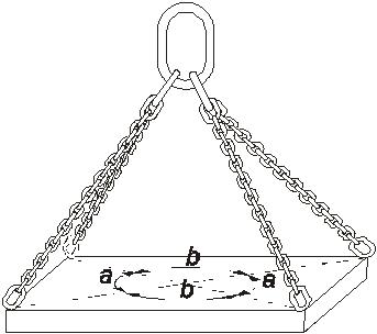
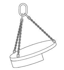
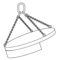
The weight of the load to be lifted should be divided equally amongst each chain strand. This is the case when the chain strands are ordered symmetrically to one another; which means that: with a three-strand lifting chain, the lifting points should be the same distance apart or rather that they depict an equilateral triangle with each angle at 120° (see figure 1). with a four-strand lifting chain, the lifting points should depict a rectangle or square with pairs of angles identical (see figure 2).
EN 818-6: The load can be seen as symmetrical only when all the conditions set forth below are fulfilled:
• The load is less than 80 % of the specified carrying capacity and
• The angle of inclination of all chain strands is no smaller than 15° and
• The angle of inclination of all chain strands is the same and/or differ by maximum 15° and
• In the case of three or four strand chains, the corresponding angles differ no more than maximum 15°
Before choosing a four-strand chain for the lifting procedure, a properly trained person should make sure that this is the correct option for the task in hand so as to prevent overloading. It is therefore indispensable to adhere to the following safety instructions:
BGR 500: A load difference of no more than 10 % on the chain strands can be disregarded. This is the case when the angle of inclination of each chain strand differs by a maximum of: an angle of inclination up to 45° – maximum 6° difference an angle of inclination up to 60° – maximum 3° difference
Chain shortener: The available chain shorteners (type PWP, PSWP, PW, PSW, XKW, KPW, KPSW, KVS, VLWI) can be used to vary the length of the chain. This is necessary when changing the angle of inclination and in order to balance out asymmetries in the arrangement of lifting points, so that the load is lifted horizontally and the weight is equally distributed on each chain strand. The desired length from the lifting point to chain shortener is configured; the next chain link is then mounted on the hook – it may be necessary to perform an adjustment (see figures below).
Shocks: Loading must be free from shocks and impacts.
The load weight: The chain strands must be twist- free and in a straight alignment (not knotted) or free from bending (corners). Hanging rings and hooks and/or other accessories and joining elements of the load or the crane must also be able to move freely and oriented in the load direction.
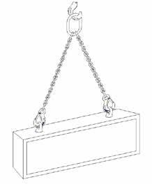
Methods of lifting: lifting chains can be attached in multiple ways to the load:
Direct method – here the elements are linked directly to the lifting points (eyes or hooks) on the load. The correct fit of hook and lifting points must be taken into consideration so that the weight is distributed on the hook base rather than the tip of the hook. The safety catch must be closed.
When using multi-leg chains, the hook tips should all point outwards unless the hooks serve a different function (e.g. sheet metal hooks BWW or fork hooks GHW). The orientation of the hook tips can be manipulated by turning the hanging rings – underside up.
Method entwined – A chain strand is threaded through or under a load and the elements are directly attached to master/rigging link or crane’s load hook. In general, this method uses two lifting chains but is not suitable for lifting loose bundles as parts of the load can shoot out in the travel direction when breaking. A single strand lifting chain can be used if the outer shape of the load allows for this, providing that the chain is threaded through the load, namely above the centre of gravity so that it cannot tip over.
Method double entwined – This method provides increased safety when lifting loose bundles as the load is doubly surrounded.
Special care should be given to the load capacity when using single or double entwined lifting chains; the load capacity of a single lifting chain remains the same as long as the hook is mounted into the master link. If, however, a circle is formed using a single chain and is then mounted directly onto the crane hook, the load capacity is that of a two-strand lifting chain (see figures 5-8).
Implementation-related Limitations
Special lifting chain methods: Some methods of using lifting chains reduces the load capacity:
Method single choke hitch: With this method, a chain strand is laced through or under a load and the element (e.g. hook or ring) is mounted on the chain itself. This can be used when there are no suitable lifting points and provides the added benefit that the lifting chain holds the load together. When using this application method, the appropriate angle of inclination can be configured without using force (see figures 9-13). Using the choke hitch method, the load capacity (WLL) – according to the load capacity table – is 80 % of the load capacity specified on the tag.
Method double choke hitch: This method allows further safety when lifting loose bundles by gripping the load together (see figures 11 and 13). Using this method, the load capacity (WLL) is also 80 % of the load capacity specified on the tag. If two chains strands are used in either a single or double choking hitch, the following should be noted:
• If no torque should influence the load, then the chains should be laced the same
• If the load should not roll away when lifting, a reverse choke hitch is to be used (see figures 12 and 13)
More than two chain strands should not be used, as the weight of the load will not be equally distributed.
Temperature: Lifting chains can be used partly above the specified application temperature with limitations. Higher temperatures mean that the load capacity is reduced. The permissible temperatures along with the associated reduction factors can be found in the table with the demanding conditions. The permissible load capacity with higher temperatures comes about by multiplying the load capacity on the tag with the corresponding reduction factor from the table. However, it is harder to estimate the exact maximum temperature the chain can withhold in praxis – one should always assume a higher temperature for safety purposes.
The reduction of load capacity with higher temperatures should always be applied until the chain and/or the parts have cooled down to room temperature.
Lifting chains should not be used outside of the specified temperature range; if the chains are used by accident outside of the temperature range, they must be taken out of operation.
Impact/shocks: If loads are accelerated or slowed down abruptly, high dynamic forces are applied which increase the tension on the lifting chain. Operating conditions which are to be avoided occur due to sudden or impulsive loading. Impacts are divided into three categories which are listed in the accompanying table along with the reduction factor. The permissible load capacity of the chain sling in this case arises from multiplying the load capacity of the tag with the corresponding reduction factor.
Vibrations: pewag lifting chains and accessories are designed for 20.000 load cycles. Nevertheless there is always a danger that the chain or the components will become damaged from the high dynamic stress involved. According to the trade association Metall Nord Süd, these stresses on the working load can be mitigated by increasing the nominal thickness.
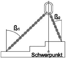
Asymmetry: If the chain strands are not ordered symmetrically and do not show the same angle of inclination – as described under the subtitle “Angle of Inclination” – the load is asymmetrical and the weight will not be equally distributed on all chain strands. In this case, a professional should be called and the following should be observed:
Asymmetrical arrangement of the chain strands and unbalanced angles of inclination can overlap or offset each other. If the angle of inclination differs amongst each strand when using two, three or four strand lifting chains, then the most stress can be found on the single strand with the smallest angle of inclination (see figures 14-16). The load capacity according to the tag must be accordingly reduced by the WLL of one or more chain strands so that no single strand is overloaded. In the extreme instance, a vertically suspended single strand will carry the complete load.
Angles of inclination smaller than 15° are to be avoided as this can lead to a higher risk of load instability; unwanted vibrations and load sway will further increase the stress on the chain strands causing further overloading.
If in doubt, only one chain strand should be seen as carrying and the load capacity of the lifting chain should be reduced. Alternatively, the load capacity on the tag should be reduced by half.
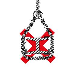

Examples of asymmetry:
Center of gravity
Edge load: It is advisable to take extra precautions on areas where the chain strand meets the load as sharp corners on hard materials can bend or damage the chain links. Conversely, the chain strand can damage the load due to high contact pressure. An intermediate layer such as wood blocks can reduce such damages from occurring. For the right and/or wrong usage, take note of the following figures:
If chains are mounted around a load (e.g. support arms), the diameter needs to be a minimum 3 x the chain pitch (inside chain link length); if using a smaller diameter, the load capacity must also be reduced by 50 %. If chains are guided around corners without the appropriate protection then the load capacity of the chain must also be reduced. The criteria for correct protection and the degree of reduction when using ill-fitting or no protection is dependent on the radius of the corner – it does not matter if it is the corner of the load itself or of the corner protection. The criteria along with the associated reduction factor can be found in the table below. The permissible load capacity of the chain sling in this case arises from multiplying the load capacity on the tag with the corresponding reduction factor.
Reduction Factors
The maximum permissible load capacity of the chain sling arises from multiplying the load capacity on the tag with all the corresponding reduction factors in this table.
Reduction Factors
Temperature
Asymmetrical Load
Shocks/Impacts
See reduction factors in the respective programmes
The load capacity should be reduced by minimum 1 chain strand, e.g. III or IV- leg chains are classified as II-strands. In cases of doubt, assume that only one strand is supporting the weight slight shocks arise from e.g. acceleration when lifting or lowering medium shocks arise from e.g. the lifting chain shifting after fixation around the shape of the load strong shocks arise when e.g. the load falls into an unloaded lifting chain not
Not utilising all chain strands: In praxis, lifting situations arise where not all chain strands of a multi-leg lifting chain will be used simultaneously or situations where more than one lifting chain will be used at the same time. The marking on the tag in these instances is not applicable. The permissible load weight should be taken from the load capacity table subject to the chain dimension, the number of strands in use and the quality grade. Under no circumstance should the load capacity of the lifting chain exceed the markings on the tag!
Single strands that are not being used should be mounted onto the master link so as to minimise the dangers of free swinging or unintentional latching onto an object or person.
Before using several lifting chains together, one should make sure that all master links have enough space in the hook and will not unhook themselves during the lifting process. An angle of inclination of more than 45° should not occur. Only lifting chains of the same nominal size and quality grade should be used simultaneously; otherwise the smallest nominal size needs to be used to determine the maximum permissible weight that can be lifted.
High-risk conditions: This instruction manual assumes that the lifting chains are being used in low-risk situations. High-risk conditions are classified as offshore-operations, lifting of people or potentially dangerous loads such as liquid metals or nuclear materials. In such cases, the permissibility and the degree of risks should be clarified with pewag.
Handling Errors
Amending the as-received condition: a change in the as-received condition is not permissible; in particular, pewag’s lifting chains should not be welded or exposed to heat over the maximum permissible temperature –see “Temperatures” in the corresponding tables.
The shape of the lifting chain should not be changed by bending, grinding, cutting off pieces, drilling holes etc. For the user’s safety, safety aspects such as locking devices, safety mechanisms (pins or sleeves), safety catches etc. should not be removed.
Subsequent surface coatings are only allowed if one can make sure that no harmful chemical reactions take place during the process as well as after which could harm the chain’s function. Hot-dip galvanising and other zinc plating should therefore not be carried out on grade 8, 10 and 12 lifting chains. Pickling and stripping are also dangerous processes and the suitability should be clarified.
Food, pharmaceuticals, cosmetics and chemicals: pewag lifting chains should not be used for lifting foodstuffs, cosmetic or pharmaceutical products as well as under heavily corrosive influences (e.g. acids, chemicals, sewage). They should not be exposed to acid or chemical vapours.
In general, pewag lifting chains should not be used for the transportation of people or used in explosion-protected areas, neither should they be used to lift liquid metals.
Chain strands should not be entwined or knotted together.
Hooks should not bear weight on the tips.
More detailed information can be found in the specifications of the different quality grades.
Replacement parts to be used
Replacement parts should only be changed by qualified persons with the necessary skills. Only original pewag replacement parts are allowed to be used; only new bolts, clamping sleeves and other safety elements should be used.
Protective measures to be taken by the user
Gloves should be worn during fastening as well as during lifting. When using the lifting chains in situations of implementation-related limitations, the reduction factors concerning load capacity must be taken into account so that sufficient safety is ensured.
Residual risks
Residual risks occur primarily as a result of non-observance of the operation instructions and/or the conventional lifting techniques; hence it is necessary that only properly trained personnel assess and implement the lifting procedure.
Overloading caused by non-observance of the maximum load capacity or disregarding the reduced load capacity due to temperature influence, asymmetry, edge or impact loading can also lead to the failure of the lifting chains as well as using the wrong replacement parts, exceeding the angle of inclination, strong vibrations/oscillations caused by overloading or the use of untested and/or twisted or knotted chains. This can lead to the failure of the lifting chain that further leads to the load falling and injuring personnel present in the danger zone of the hoisting device.
Lifting a rigid load with a four-strand lifting chain means that most of the weight is carried by either three or only two of the strands so that the remaining strands are purely for stabilising the load. This is especially the case when the chain strands have not been shortened correctly; the strands are not of equal length and/or the lifting points have not been precisely positioned. Once again, there is a danger that the chains become overloaded and break.
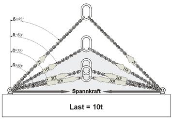
With increasingly higher angle of inclination, the power in the chain strands and also the tension force (horizontal power component) on the load increase – see image 19. This can lead to damage/breakage of the load or lifting points.
If the centre of gravity of the load is above the lifting points, then the load can become instable and can tip over. This danger increases when the angle of inclination is below 15° as the load swings more.
Accident/Breakdown Procedure
The lifting chains need to be taken out of operation immediately in the event of an accident or unforeseen incident – e.g. accidents, overheating, overloading, collisions, acid and chemical influences. In doing so, it must be ensured that through the removal of the lifting chain the load and personnel are not harmed in the process, e.g. because the load was set down in an instable manner, it could tip over. If deemed necessary, an additional chain can be mounted before the damaged one is removed – the chain should then be given to a qualified person for evaluation.
Evaluation, Repair, Maintenance
The safety of the chain can be influenced during its natural work life; it is therefore vital that to maintain it in a good state of use through periodic maintenance, evaluation and repair.
Maintenance: Lifting chains should also be cleaned, dried and safeguarded against corrosion, e.g. lightly oiled. Especially accessories that have movable parts such as bolts or bearings need to be oiled to protect them from corrosion, increased wear and seizing.
Inspection before initial use: Before using a lifting chain for the first time, the following points should be checked:
• The lifting chain corresponds to what was ordered
• The test certification and/or the declaration of compliance and conformity are present
• The CE-marking and load capacity on the lifting chain correspond to the details on the certification and declarations
• Recording individual details of the product into a chain card index
• This manual is included with the lifting chain and that every employee reads and fully understands what has been written
Inspection before every use: The chain should be checked to make sure it is in a good state before each and every use by the operator. He should pay attention to obvious damages or signs of wear; if in doubt, or if the chain fits into one of the below-mentioned “discard” categories, the chain should be taken out of operation immediately and given to trained personnel for evaluation.
Evaluation: Evaluation of the lifting chain should take place after it has been cleaned – it must be free from oil, dirt and rust. Painting is only admissible as far as an evaluation of the chain sling condition is possible. Methods of cleaning that cause embrittlement of the material (pickling), overheating (burning), abrasion of material (sand blasting) are not permitted; cracks or other defects should not be hidden. Sufficient lighting during evaluation needs to be provided; the whole of the lifting chain should be inspected; if in doubt, the chain should be sent back to the manufacturer for evaluation.
Inspection after an unforeseen incident: The lifting chain needs to be taken out of operation immediately and given to trained personnel for evaluation in the event of an unforeseen incident – e.g. accidents, overheating, overloading, collisions, acid and chemical influences.
Inspection carried out by trained personnel: Trained personnel should carry out periodic inspections based on the national legal requirements; if not otherwise specified a minimum of every twelve months. This time frame should be shortened for lifting chains in frequent use at maximum load capacity or under implementation-related limitations, in the case of increased wear or corrosion. The inspection includes both visual and functional testing. After long periods in storage, the lifting chain should be checked thoroughly by trained personnel before initial use especially if the date for inspection has been exceeded or the product was stored incorrectly – see below.
Load Test: A load, visual and function test needs to be carried out by trained personnel at least every two years. This time frame should be shortened for lifting chains in frequent use at maximum load capacity or under implementation-related limitations. The load test should be carried out with 2 times the working load limit. It can also be replaced by a crack detection test – e.g. by a magnetic crack test or a dye penetration method. In this case, the chain sling must be checked throughout its length. Note: The interval of the load test may vary due to national regulations.
“Discard categories“: If the lifting chain falls into one or more of the below-stated categories, then it should be taken out of operation immediately:
• Breakage
• Missing or illegible tag/marking
• Unrecognisable identification marking of components
• Distortion of suspension components, accessories or the chain itself
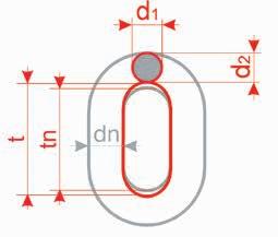
• Chain stretch: if the length of the chain links is different or lack of mobility between the links or an obvious difference between the individual strand lengths is observed, then it could be possible that the chain has been stretched. The chain needs to be disposed of if the inner link pitch t>1,05tn, whereby tn equals the nominal pitch of the chain link
• Wear: often occurs due to contact with other objects mostly on the surface of the chain links, thus being easily identifiable and measurable; and between chain links where it is hidden. When carrying out the inspection, the chain should be loose and the chain links rotated so that the measurable cross-section (e.g. one of the inner contact surfaces of the chain link) lies exposed. The mean diameter dm is permitted to be 90 % of the nominal diameter dn. dm is determined as the mean value of the diameters d1 and d2 measured at right angles on the corresponding cross section. The chain must be discarded if:
2 dm = d1 + d2 ≤ 0,9 dn
Maximum permissible dimensional changes with regards to the nominal dimension:
Clevis and Connex pins
LHW, KLHW, WLH(B)W, LHWP d2 h
Tip opening
-10 %
2 x smax
*) HSW, WSBW, FW, PW, PSW, KHSW, GKHSW, KCHW, KFW, KPW, KPSW, XKW, KOW, KRW, KVS, WS, SH, PWP, PSWP, HWF, HSWI, VLWI, HSWP, KHSWP
• Cuts, notches, grooves, cracks: these defects, especially across the tensile direction) can lead to sudden breaks!
• Excessive corrosion (e.g. pitting corrosion), material discolouration from heat, burning of the outer surface coating, evidence of subsequent welding
• Missing and/or defective safety measures as well as evidence of the hook being over-extended. The opening of the hook should not exceed 10 % of the nominal dimension. A swing-out safety catch is proof that the hook has been overloaded
Repairs: Subsequent repairs should only be done by qualified personnel with the necessary know-how and experience.
When carrying out repairs, the chain as a whole must be repaired; individual pieces that are broken, obviously deformed or stretched, heavily corroded, coated with non-removable debris (e.g. weld splatter), have deep cuts, notches, grooves, cracks should be replaced immediately. Missing safety device such as safety latches, triggers, pins as well as damaged, broken or missing springs should be replaced. Only use original pewag replacement parts and accessories of the correct quality grade and nominal size. winner accessories can be used to repair Nicroman lifting chains – new bolts, adapter sleeves and other safety elements are advisable.
Missing identification tags can be replaced with a new tag, but only after all the necessary tests have been conducted and the load capacity is ascertainable using the markings on the individual parts and type.
Small cuts, notches and grooves can be eliminated (e.g. on large hooks or lifting chains) by carefully grinding or filing. The newly repaired part should blend seamlessly into the adjoining material without there being a marked difference in the cross-section. Through eliminating the damage, the material thickness must not have decreased by more than 10 % – after the repairs, the chain should not fit into any of the “discard” categories.
Repairs that involve welding should only be carried out by pewag.
Documentation: The tests conducted by trained personnel, the outcomes as well as the maintenance logs should be documented in a chain card index which should be kept for the whole of the product’s working life. These recordings and/or the manufacturer’s declaration of compliance and conformity need to be shown to the national trade control on demand.
Storing, Transportation
Lifting chains that are not being used should be stored on designated frames and not in a heap on the floor as that would be the fastest way to damage them.
If unloaded lifting chains remain on the crane hook, then the end hook must be attached into the master link or, if this is the case, the end links into the crane hook in order to reduce the risk chains sling legs swinging freely or accidentally unhooking.
If the lifting chains will not be used for long periods of time, then they should be cleaned, dried and protected against corrosion (e.g. lightly oiled) before being stored. When the chain sling has been stored for a long period and the regular inspections have not been made, or it has been stored incorrectly (see also inspections), an inspection must be carried out before the first use.
Guidelines for the implementation of lifting procedures
The following guidelines should support the user in the preparation and execution of lifting procedures. They are by no means exhaustive and should not replace proper training; hence the ISO 12480-1 will also be referenced.
Before commencing lifting, one should check that the load can move freely and is not anchored or attached to something else.
It is important that the weight of the load to be lifted is known. If it is not specified, possible information can be taken from the shipping documents, handbooks, plans etc. If no information can be found, then the mass should be estimated by calculation.
The lifting points of the lifting chain must be proportioned to the load’s centre of gravity so that it does not tilt or topple over:
• The lifting point needs to be vertical over the centre of gravity when using a single-strand lifting chain and basket chain
• The lifting points using a double-strand lifting chain need to be symmetrical on both sides above the centre of gravity
• The lifting points on a three or four-strand lifting chain must be at the same level above and evenly distributed around the centre of gravity – see the explanation on “Angle of inclination” under the “Intended Use” heading
All multi-leg lifting chains produce a tensioning force (horizontal power component see figure 19) on the load that increases when the angle of inclination β of the chain increases. Always ensure that the load to be moved can withstand the horizontal power components without becoming damaged in the process. The grey-shaded area depicts an angle of inclination of greater than 60° wherein which a lifting chain should never be used. If chains are put through a barrel hook (e.g. drum chain slings), then the horizontal power component is much greater than the angle of inclination of the chain suggests. Hence the angle of inclination in this case should be no more than 30° (see figure 20).
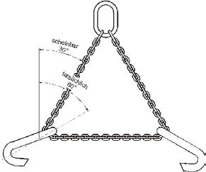
Only after considering all the above information, can the appropriate lifting type and necessary strand number be chosen correctly.
Possible limitations (e.g. temperature influence, asymmetry etc) need to be identified in order to determine the appropriate load capacity of the lifting chain.
The load hook wherein which the lifting chain is mounted, must be directly over the load’s centre of gravity. Only then can the load hook, by means of the lifting chain, be connected to the load and the individual strand lengths – as in the case of a multi-leg lifting chain – are adjusted accordingly, so that all strands will be equally taut during lifting. The angle of inclination must lie within the specified range. To prevent the load from swinging dangerously, and to retain the exact position when setting it back down, it is recommended to use a lanyard.
Hands and other body parts should be kept at a distance when tightening the limp chain to prevent accidents from happening. The load should be slightly lifted to make sure that it is safely mounted and stays in the upright position; this is especially important using the entwined and laced method where the load is held using friction. If the load starts to tip, it should be placed back on the ground and remounted – e.g. by either changing the lifting points position and/or using shortening elements.
The area where the load is set down should be prepared. The ground should be able to carry the weight of the load; however, underground cavities and pipelines must not be forgotten and damaged in the process. There should be enough space to and around the intended final position; furthermore, no people should reside in the area. It may be necessary to have wood or other similar material around to help stabilise and protect the load and also to protect the ground.
The load should be set down carefully. The lifting chain should not be squashed under the load as it can become damaged this way. Before the chain is loosened, the load needs to be checked for stability – this is especially important when lifting loose bundles. Once the load is on the ground, the lifting chain should be removed by hand – it should not be pulled out using the lifting gear as the chain could catch and the load could tip over. The load should not be rolled over the lifting chain either as this can also damage the chain.


