Pierre Teo
National University of Singapore Department of Architecture
B.A. (Arch)
About Me
Pierre Teo
pie.rre.teo@mail.com
+65 93299091


Pierre Teo
National University of Singapore Department of Architecture
B.A. (Arch)
Pierre Teo
pie.rre.teo@mail.com
+65 93299091
& Computer Science Minor
National University of Singapore
2022 - Present
Job shadow / Internship
2019 Nov'
Prior to formal architecture education, I quickly learnt 3D modelling software to assist in the firm's projects. Attending meetings and site inspections, I sought to learn about the industry and the profession.
YEAR 2 SEMESTER 1
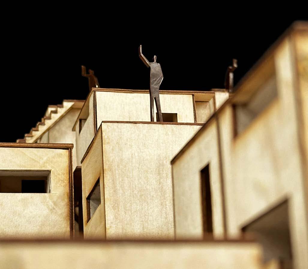
Aggregation of individual architectural forms into collective spaces through the deployment of cuboid geometry as a key form driver

Adobe Illustrator
Adobe InDesign Blender
The Architecture Society ��
Vice-Director of Communications
2023 Nov' - Present
Managed and created architecture-related content for multiple social media channels.
2022 Mar' - Aug'
Ideated various projects while spearheading new organisational systems in the company. Assisted in event shoots and edited content.
Freelance Video-editor
2021 Dec' - Present
Worked on and managed various video and motion-graphic projects for corporate clients (AXA, HSBC, Fairprice Group).
Form creation of a residential/office space through programmatic and site pressures

YEAR 1 SEMESTER 1
Abstraction of phenomena into systems which are then manipulated through sets of parameters


YEAR 2 SEMESTER 1
TUTORED BY YANG HAN ��
This project explored the ideas of visual and physical connectivity within, between, and across dwellings.
Seen / Unseen
Each cube has a specific spatial quality
Visual or Physical connectivity (or the lack thereof)
A 3rd layer of connective complexities are added in the creation of a dwelling group
As dwellings, a 2nd layer of connective complexities are added between cubes
Dwelling group has layers of visual connectivities
Each dwelling boundary spans various cubes
Adaptation of a cube to form a structural core allows for
1. rotation
2. mirroring
3. stacking
Ground-level dwelling groups face community spaces in surrounding site
Aligned grids allow for close packing, while intersecting grids forces winding gaps
Facade was curated with this framework to allow or prevent sightlines 4
BEFORE RESOLUTION
MATRIX OF OPENINGS
AFTER RESOLUTION
CREATING FUNCTIONAL SPACES
Based on function, an appropriate opening is placed

The collective form is generated from stacking modified instances of dwelling groups (outlined in black)
A series of pathways allow for horizontal connection (black arrows) between otherwise separate towers


Detail resolution and curating lines of sight rendered every face of each dwelling unique
To process the ~1000 unique pieces, I created a script in Grasshopper to tag and lay out every part for laser-cutting

PART TAGGING ON RHINO MODEL


CORRESPONDING LASER-CUTTING FILE


YEAR 1 SEMESTER 2
TUTORED BY WILLIAM NG ��
This project utilized wind flow as a primary form-driver, informing the formal expression as well as arrangement of spaces.
OCCUPIER 1 SPEAK-EASY / CAFE OWNER
OCCUPIER 2 CANVAS GRAFFITI TEACHER
OCCUPIER 1 2 1 BEDROOM
SUNTUES WED - SAT
2
Occupiers were chosen due to their unique displaced schedules
WIND ON SITE

WIND SIMULATED ON BLENDER RESULTS WERE ADAPTED TO 2D GRAPHIC
VOLUME ALONG WIND-FLOW DIAGONAL TO WIND-FLOW Studio, bar, and back-of-house Office, living & dining rooms, kitchen, and bedroom


AIRFLOW SIMULATED ON CFD SOFTWARE RESULTS WERE ADAPTED TO 2D GRAPHIC
KITCHEN
KITCHEN
PROGRAMMATIC NETWORK
Their daily schedule was postulated then translated into a programmatic network

CREATION OF LINKS BETWEEN WIND CHANNELS

Spaces are located based on their suitability for wind-flow and programmatic network
PROGRAMMATIC LAYOUT

COMBINING SPACES INTO NEW FORMS


AIRFLOW SIMULATED ON CFD SOFTWARE
RESULTS WERE ADAPTED TO 2D GRAPHIC
ENSURING PRIVACY


EXPOSED OPENING
ROUNDED RINGS
BREAKDOWN OF FORM
PRIVACY MAINTAINED
ORIGINAL FORMSHARP EDGES


Rounded edges reduces airflow resistance
MODIFIED FORMROUNDED EDGES


ROUNDED RINGS
Formed by function
SPACES
Made habitable through stacking
VOLUMES
Combination of various congruent functions
AXONOMETRIC


SECTIONAL MODEL
LEFT SIDE

SECTIONAL MODEL FRONT


Designing the building parametrically allowed for nonlinear iteration and freedom in altering building form
GRASSHOPPER SCRIPT

This helped me navigate the design of complex spaces, such as the connection�� between studio, office, and residential, which involves intersecting and crossing slopes

INTERMEDIATE STEP DURING FORM-FINDING
TOOLS & DELIVERABLES

GRASSHOPPER SCRIPT
�� TRANSLATES SPACE TO RINGS

�� THICKENS PLANES TO WALLS
�� LAYOUT TOOL FOR LASER-CUTTING
�� DELIVERABLES FOR BOARDS


YEAR 1 SEMESTER 1
TUTORED BY YONG SY LYNG ��
This project explored the abstraction of a physical chaotic system into Grasshopper, which was then expanded on and modified.
Sound is played through a speaker at the base of a chamber
10CM
10CM
30CM
Various frequencies and wave types were tested for unique variations in ball response
Utilizing balls with varying masses allowed for analogies to be built for more concepts
NUMBER OF BALLS VARIABLE
NO. OF FRAMES CONSTANT


NUMBER OF BALLS VARIABLE OCCURENCE OF BALLS CONSTANT


SPEAKER FREQUENCY VARIABLE BEAD / BALL RATIO CONSTANT


CREATE STARTING POINTS
N random points are located according to a Normal Distribution
A random movement vector is assigned for every point to analogize random brownian motion
Vectors are scaled in the z-axis based on the Hz value of the simulation
LOOP REPEATEDLY
Random movements are repeatedly assigned iteratively to every point


Connections are created between a 4 x 4 x 4 grid of balls according to Connection %
PROPEL FROM REST
A physics simulation is ran to allow balls and connection to achieve rest
A explosion placed distance d from the base plane then propels the balls outwards
CAPTURE AT BALL PEAK
The frame with the highest ball position is captured
CONNECT NEARBY BALLS
X = 20% 24 x 20% ≈ 5 24 x 80% ≈ 19 80% d


