
14 minute read
Recent progress in the understanding of dense phase flow stability

Recent progress in the understanding of dense phase fl ow stability

Dr Ognjen Orozovic specialises in pneumatic conveying as a Research Associate with the Centre for Bulk Solids & Particulate Technologies at the University of Newcastle (UoN). In this article, Dr Orozovic reviews recent developments in pneumatic conveying research at UoN.
THE RELATIVELY LOW NUMBER OF
moving parts, flexible routing and fully enclosed transport are some of the unique advantages of pneumatic conveyors that have resulted in their widespread applications in industry. Where possible, low velocity dense phase pneumatic conveying offers favourable conditions in regard to operational efficiency and pipeline`wear.
Unfortunately, the highly dynamic and complex nature of dense phase flows remains a challenge for the development of reliable design and analysis tools, which are required for the potential of these flows to be realised. Within the field, steady-state is often assumed as a simplification; however, there currently is limited knowledge on which conditions a steady assumption is appropriate for such dynamic flows.
Recent studies at the University of Newcastle [1–3] have investigated this knowledge gap in dense phase flow stability, such that more appropriate design and analysis tools for these complex flows can be developed.
Stability analysis
Simplest case of single slug conveying Slug flow and fluidised dense phase are similar for being discontinuous wave flows. However, there are differences in both the waves themselves and the layers of material separating these waves. The relatively less dynamic slug flow, with its stationary layers and equal particle velocities throughout the wave, is the simpler of the two dense phase flows when considering stability.
The simplest case for analysis of dense phase stability is that of single slug conveying. In slug flow, a slug wave propagates through the stationary layers of material that partially fill the pipeline (Figure 1). Material is pickedup from the stationary layer ahead of a slug and at the same time material is being dropped off from the slug to form a stationary layer behind itself. This particle exchange between a slug and its stationary layers is responsible for the slug wave travelling faster than the particles within it. This is because the wave velocity vw is the sum of the particle velocity vp and the perceived velocity from these particle exchanges, which effectively translates a slug in space and is termed as the velocity c.

Figure 2: Single slug showing fundamental parameters, and particle exchanges with stationary layers.
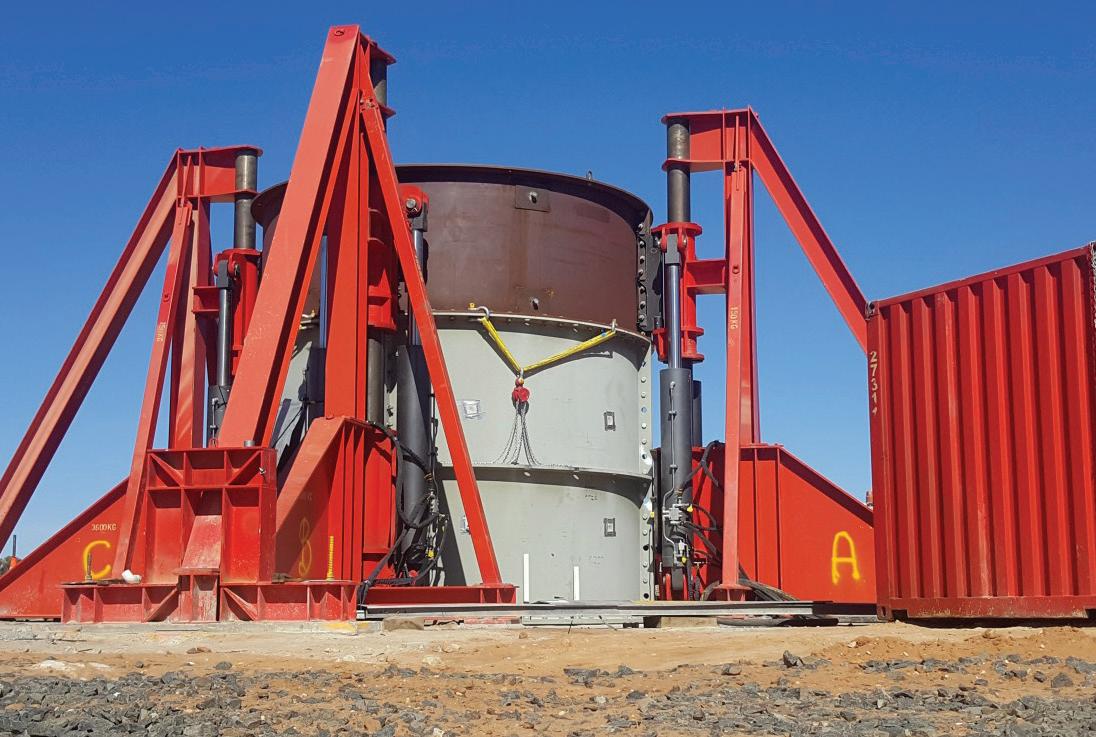
Figure 1: Pneumatic conveying testing facilities at the University of Newcastle.

Taking into account the slightly aerated state of a slug through the slug to bulk density ratio E, it can be shown [4] that the relationship between these velocities is v w=E(vp+c). What this formula means is that if an observer is moving alongside the slug at its wave velocity vw, they would observe individual particles travelling backwards through the slug at a velocity of c. Through conservation of mass, one can then analyse the dynamic changes in slug length L by considering the difference between how much material a slug picks up at its front and how much it deposits at its rear:
The first term on the right-hand side represents the material picked-up at the slug front, which is proportional to the product of the wave velocity vw and the fraction of the pipeline area occupied by the stationary layer α, and the second term represents the material deposited, which, as alluded to earlier, occurs at a rate proportional to the velocity of c. To analyse the stability of the solutions to Eq.(1), we desire the right-hand side to be a function of the slug length L. This can be achieved for single slug conveying by considering the solids mass flow rate ṁ s :
Where ρs is slug density, A is the pipeline cross-sectional area and Lp is pipe length.
The solids flow rate is just the slug mass (ρs AL) divided by the time that it takes for the slug to travel the pipe length (vW /Lp). From this, the slug wave velocity vw can be made the subject and substituted into the conservation of mass expression of Eq.(1) to examine its stability:
A fixed point is where the solution is not changing and can be found by setting dL/dt=0. Solving Eq.(3) we can see that there is only one fixed point for L and we can study its stability using linear stability analysis – a mathematical technique that examines whether perturbations around a fixed point converge back to the fixed point (stable) or diverge from it (unstable). It can be shown that a solution is stable only when d/dL (dL/dt)<0 and this is because perturbations are exponential with d/dL (dL/dt) and converge only when d/dL (dL/dt) is negative (i.e. a decaying exponential).
All of the individual parameters on the right-hand side of Eq.(4) can only be positive. Therefore, due to the negative sign out the front, d/dL (dL/dt) is always negative – proving that the single fixed point of Eq.(3) is stable. Physically, this means that single slug conveying is stable and consequently heads towards a common steady-state regardless of its initial conditions. Just as significantly, the above method is also capable of indicating the time a single slug system requires to reach its steady-state through the use of the

reciprocal of Eq.(4) (the “characteristic timescale” or “time constant” of the system, which, too, is independent of initial conditions). These significant findings predicted by theory have been validated using single slug coupled Computational Fluid Dynamics and Discrete Element Method simulations (CFD-DEM [1], with an example of results for inlet gas velocity ug=4 m/s and layer fraction α=0.23 shown in Figure 2.
Global steady-state for dense phase fl ows Theoretical foundations, such as the single slug work above, are desirable due to providing general relationships under known assumptions and conditions. This simultaneously illuminates new research directions, as well as providing immediate and quantifiable tools for their analysis.
One area where we can extrapolate the simple single slug analysis from above is when considering global stability of a multiple slug system. Since Eq.(2) is based on conservation of mass, and is therefore general, it may be carefully applied to analysing systems of multiple slugs. We can consider a control volume over an entire pipeline and treat all of the individual slugs as a combined length L. As the product Lvw must be constant, an equivalent wave velocity vw can be calculated from Eq.(2).
Unfortunately, even this combined length and equivalent wave velocity process does not guarantee unique values of L and v w, as there is an infinite number of combinations of L and v w that satisfy Eq.(2) for a constant solids mass flow rate. However, this result of no unique solution for fixed solid mass flow rates makes physical sense when considering that air mass flow rate is a free variable in our analysis. In other words, we hypothesise that when solids and air mass flow rates are fixed, not only is
the product Lvw constant but so are L and v w individually. Assuming the above to be true, stability analysis of global conditions in a multiple slug system is actually identical to the previously solved single slug case.
Figure 3 shows the experimental results of Lecreps [5], who conveyed plastic pellets in an 80 mm ID pipe of 35 m length containing a combination of vertical and horizontal sections and three bends. As it can be seen, the inlet pressure, which is proportional to the combined slug length [2], heads towards a clear steady-state. These results support the theoretical analysis and the assumption that fixed solids and gas mass flow rates result in unique L and vw values, even for multiple slug systems.
Examined from another perspective, the above results of stable inlet conditions are unsurprising given that “conveying characteristics charts”, which have been used as a design tool for decades, are possible only because there is a global steadystate. This is where the above slug flow results may be related to fluidised dense phase, since fluidised dense phase also exhibits clear globally stable behaviours. Therefore, based on a combination of the theoretical analysis and practical observations, a similar argument about a combined dune length can be concluded to be the case for fluidised dense phase as well.

Figure 3: Simulation results of diff erent initial slug lengths all converging to the same steady length [1]. Multiple slug conveying The remaining question is whether individually stable dunes or slugs are possible in multiple dune or slug dense phase flow. In other words, we know the combined slug or dune length tends to a steady-state; however, are the individual slugs and dunes steady themselves? For fluidised dense phase, visual observations of the highly dynamic flow gives confidence that it is highly unlikely that individual dunes can ever be stable. On the other hand, until recently this was an open question within slug flow and was often an assumed simplification in modelling.
Unfortunately, expanding the above single slug conservation of mass analysis to multiple slugs is far from trivial due to a slug velocity and length not only being interrelated, but also coupled to the other slugs in the system. Therefore, our recent approach examined gas conservation of mass in the air pockets separating slugs [3]. An infinitely long pipeline with n slugs was considered, as shown in Figure 4. Assuming an ideal gas, our approach for analysing multiple slug stability was to also assume stable air pocket pressures (which implies steady slug length) and slug velocities, and analysing the resulting constraints required to achieve these conditions.
Examining the rates of change in the mass of air in the air pockets

Figure 5: Diagram of the system of n slugs analysed for stability [3]. results in the coupled equations given by Eq.(5). The subscripts correspond to

Figure 4: Example of pressure response for diff erent pipeline locations [5].
the air pocket number and ṁ is gas mass flow rate (by definition, ṁ0 is the gas mass flow rate in to the system), P the absolute pressure in the air pocket (by definition P0 is the inlet pressure and P n is the outlet atmospheric pressure), A is the pipe cross-sectional area, R the gas constant, T is temperature and vp is particle velocity.
Similarly to before, we begin the analysis with the simplest case, which is of n slugs travelling at the same velocity. From Eq.(5), we can see that the assumption of the same velocity for all slugs results in only the 0th and nth terms being non-zero. To satisfy gas conservation, we require P0 v p<pn v g, where v g is superficial gas velocity. After some algebra, it can be shown through a proof by contradiction that n stable slugs of the same velocity are not possible due to the impossible requirement of the inlet pressure needing to be below that of the pressure drop.
For the general case of stable slugs of different velocities we have more unknowns than equations; however, this gas conservation approach allows us to calculate boundary requirements for stability. Through a similar approach to above, it was shown that it is highly unlikely that 2 slugs can be individually stable, as theoretically this would require pressure drops of at least 1 atmosphere per slug. In reality, the true values

Bulk solids storage and handling solutions generated in Australia for Australian Conditions


Walla Walla, NSW Toowoomba, QLD Perth, WA
(02) 6029 4700 (07) 4634 4622 (02) 6029 4700

would be much higher as 1 atmosphere is actually scaled by the ratio of the inlet gas velocity to the particle velocity of the downstream slug, which could easily be as high as a factor of two or more. Pressure gradients of most slug flow materials and systems are typically below 10 kPa/m, meaning that stability would require individual slug lengths of well over 10 m. The analysis for n stable slugs of different steady velocities was more intricate, but effectively it involved showing that such systems are likely to converge to systems of n slugs of the same velocity – which was proven to be unstable.

Implications for conveyor design and analysis
The above methods and results have significant implications on dense phase conveying, especially in regards to existing modelling and measurement methods. In practice, flow observations and measurements are often conducted at fixed pipeline locations. For multiple slug or dune systems, the individual waves are unstable and this can greatly impact how representative such measurements are of the entirety of the flow. The recommendation for the field is that focus should instead be on measuring global parameters, such as the inlet pressure and the solids and gas flow rates of a system – as these parameters are stable and highly representative of conveyor operation.
Even for the simplest case of single slug systems, application of the single slug analysis outlined within this article is recommended. This could be to aid design and analysis decisions like: whether a certain pipeline is long enough to even attain steady operation, where measuring devices should be located to ensure a steady flow sampling and how much can a stable single slug system be perturbed and still maintain its stability.
Specifically within slug flow, it is worth noting that there exists an unstable conveying flow that is even globally unstable. This flow type is where the system cycles between slug and strand flow, in the process forming very long slugs that result in high pressures and vibrations that may damage equipment. The physics governing unstable conveying flow are poorly understood and there are no existing tools capable of predicting the risk of the flow forming. Therefore, future work will look to apply the tools developed within this article as a means for analysing this poorly understood, but important, area of dense phase conveying.
Conclusions
The stability of dense phase flows, both locally and globally, has been a poorly understood and largely understudied topic within pneumatic conveying. This article outlines the importance of flow stability and provides a summary of recent theory, validated by experiments and simulations, which shows the following: 1. For single slug systems, local and global steady-state are equivalent and proven to always be stable. 2. In general, slug flow and fluidised dense phase systems of multiple waves are globally stable due to a steady combined slug or dune length, respectively. 3. Systems of multiple slugs with identical velocities proven to be unstable. Conjectured to also be the case for the naturally more unstable fluidised dense phase. 4. Theory and observations strongly suggest that in general, individual slugs or dunes in multiple wave slug flow or fluidised dense phase, respectively, cannot be stable.
The above findings are significant for current practice and future research. Due to the unstable nature of individual waves (slugs or dunes), it is recommended that globally stable parameters, such as total system pressure drop and the gas and solid feed rates, should be prioritised instead of local wave properties. Future work will attempt to apply the theory from this article to explain the important and poorly understood unstable flow transition in slug flow, which is the only globally unstable flow within pneumatic conveying. It is clear that much remains to be learned within dense phase pneumatic conveying, but this work demonstrates that strong theoretical foundations provide a springboard for discoveries and unification.
The stability of dense phase fl ows has been a poorly understood and largely understudied topic within pneumatic conveying.
Acknowledgements
This research was fi nancially supported by the Australian Research Council.
References [1] A. Lavrinec, O. Orozovic, H. Rajabnia, K. Williams, M. Jones, G. Klinzing, An assessment of steady-state conditions in single slug horizontal pneumatic conveying, Particuology. 58 (2021) 187–195. [2] O. Orozovic, H. Rajabnia, A. Lavrinec, Y. Alkassar, M.H. Meylan, K. Williams, M.G. Jones, G.E. Klinzing, A phenomenological model for the pressure drop applicable across both dilute and dense phase pneumatic conveying, Chem. Eng. Sci. 246 (2021) 116992. [3] O. Orozovic, H. Rajabnia, A. Lavrinec, M. Meylan, K. Williams, M. Jones, G. Klinzing, Individual slugs in a pneumatic conveyor of multiple slugs are likely unstable, Chem. Eng. Sci. 250 (2022) 117365. [4] O. Orozovic, A. Lavrinec, F. Georgiou, C. Wensrich, A continuum mechanics derivation of the empirical expression relating slug and particle velocities, Powder Technol. 380 (2021) 598–601. [5] I. Lecreps, Physical Mechanisms Involved in the Transport of Slugs during Horizontal Pneumatic Conveying, Technische Universität München, 2011.


