16 minute read
A deeper understanding of conveyor pulley friction
Despite significant research, there is still much more to learn. Experts from the University of Newcastle and Elastotec investigate the emerging issues around pulley friction, the complexity of the issue, and the failures that may result.
BELT CONVEYORS FORM A CRITICAL
part of the materials handling process and have established themselves as the chosen technology for transporting bulk materials at high tonnages over long distances.
As the scale of new mining operations continues to increase, this has resulted in an unprecedented demand on these systems to convey material further, faster, and up greater elevation.
Significant improvements in the tensile strength of belts and the refinement of dynamic models to assess the transient tensions under starting and stopping conditions have allowed for reduced safety factors, greater transport distance and lift, as well as faster belt speeds. Despite the considerable amount of research that made these achievements possible, much room for improvement remains in understanding the effectiveness of drive systems to transmit the large amounts of power now required by these systems.
The drive system forms a critical component of any belt conveyor, tasked with transmitting the force required to start and stop the conveyor, as well as maintain a constant operating velocity. This force, known as the effective belt tension, is traditionally transmitted through a drive pulley, to the pulley lagging (if installed), to the rubber bottom cover of the conveyor belt, and eventually to the reinforcing carcass (steel cord or fabric) within the conveyor belt. The effectiveness of this transmission is ultimately defined within a frictional contact between the conveyor belt and the drive pulley surface.
Review of current design methods
Drive system design relies on the respective belt tension either side of the drive pulley, denoting T1 as the tight side tension, and T2 as the slack side tension. The difference between these two represents the effective tension (Te) outlined above, and the force required to be transmitted through the drive system to allow the belt to operate. The design method is well understood, based on Euler’s classic ‘rope friction’ model defined below.
T1 T 2
=eμθ Where, µ = the coefficient of friction between the belt and the pulley surface, and θ = the angle of wrap of the belt around the pulley
The simplicity of this model naturally has corresponding limitations, the majority of which are also understood within industry. The assumption that the friction is fully developed around the arc of contact relates only to rigid body contact and means that each point of contact around the pulley surface exhibits an equal coefficient of friction. This is not possible for a viscoelastic drive mechanism in shear. The gradual increase in belt tension around the drive pulley, coupled with the varying normal force (see Figure 1) results in a varying degree of viscoelastic slip within the contact, and therefore a varying coefficient of friction. For viscoelastic surfaces, friction may only truly reach is maximum kinetic value when the belt is slipping, or on the verge of slipping. Design standards such as ISO5048 and DIN22101 compensate for this by utilising
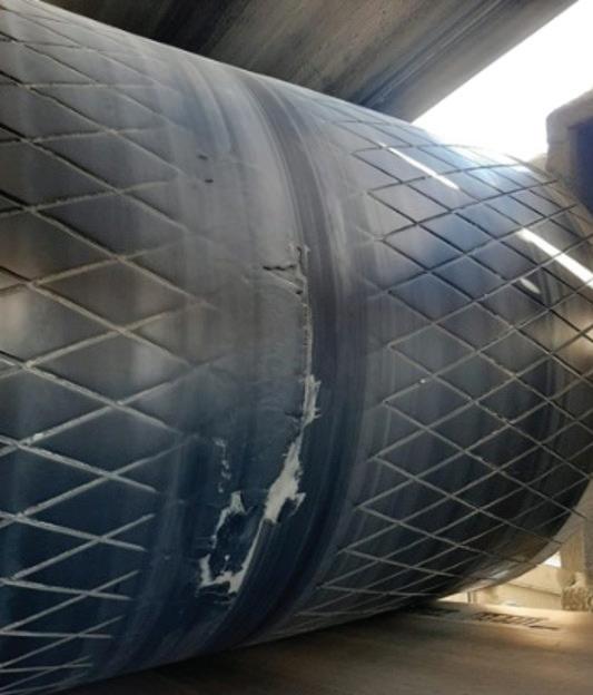
Figure 1: Euler drive friction model. Physical damage and delamination on a high-tension bend pulley began to show after three months.
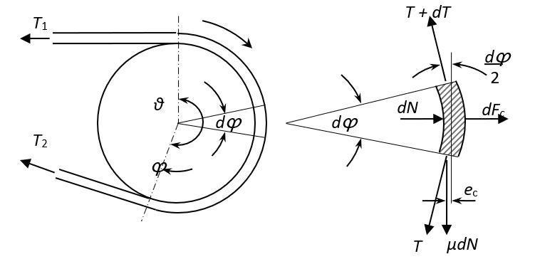
Figure 2: Tension around the drive pulley for a 210° arc of contact. a conservative coefficient of friction of up to 0.45, depending on lagging type and degree of contamination, while traditional values of kinetic friction may be as high as 0.8 for ceramic lagging [1].
Actual friction behaviour around the pulley arc
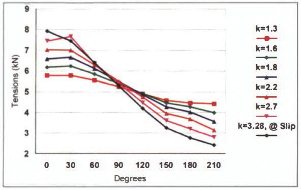
Several researchers have investigated the actual friction behaviour around the pulley arc. Work conducted by Harrison [2] developed a FEM model of the conveyor belt around the arc of the pulley, to determine the change in tension around the arc, and an effective coefficient of friction based on standard input values of 0.9 and 0.7 for static and kinetic friction respectively. His work concluded that the belt tension around the pulley displayed an s-curve response as shown in Figure 2, based on the ratio k= T 1 T 2 , with the effective coefficient of friction dependent on this ratio.
Given a value of k= T 1 T 2 , Harrison determined an effective coefficient of friction of 0.32 to 0.84, dependent on the tension in the system. A fabric belt typically corresponding to lower tensions yields a lower effective value, compared to a higher tension steel cord installation.
Work by Tiwari et al [1] investigated the viscoelastic dependency (load and slip rate) on the coefficient of friction of ceramic lagging tiles on a rubber belt. Ceramic lagging is commonly used in applications at risk of contamination, as the lagging has cylindrical protrusions extruded from the surface, which indent the rubber cover to aid traction. Naturally, this indentation is load and slip dependent, with Tiwari predicting a coefficient of friction in a planar contact region (flat surfaces) of around 0.4 – 0.8 depending on rate of slip between the two surfaces. When the ceramic protrusions begin to be contaminated by rubber shavings from belt wear, this coefficient increases to as high as 1.5 under a contact pressure of 0.62 MPa. Coefficients of friction in excess of 1 have also been measured experimentally by Robinson et al [3] for both ceramic and polyurethane lagging under a curved contact area. It is well known that these coefficients will vary with age and wear of both the pulley lagging and belt cover.
What about across the pulley face?
A more recent development is the need to develop a deep understanding of the behaviour of friction across the pulley face. Euler’s equation, as well as much of the existing research focus on understanding the behaviour around the arc of contact, operating on the assumption that the viscoelastic behaviour, and thus the coefficient of friction is uniform across the pulley width. For a new installation, this assumption is valid, however as belt and lagging wear, the belt thickness and/or pulley diameter becomes less uniform, leading to stress concentrations within the belt being transferred to the pulley lagging. Build up or contamination of lagged surfaces has the same effect.
Conveyor belts wear for a variety of reasons on both sides. The carry side of the belt (top cover) typically wears most towards the centre, at the surface in contact with the bulk material. Similarly, the return side (bottom cover) will typically exhibit localised wear associated with wing idler pressure, idler junction wear, idler skew, or any combination resulting in an uneven cover thickness. When a worn steel cord belt travels around a pulley, the arc length of each steel cord will vary across the belt width, resulting in localised stresses on the cords and splices. This stress is subsequently transmitted to the lagging, and its bonding with the pulley.
The resulting cord stresses are not directly proportional to the length of arc as one may expect. To maintain total load across the belt, cords adjacent to those with reduced load bearing compensate for the reduction in load capacity of the worn sections, leading to a peak ‘switch’ stress at the wear junction. This stress is subsequently transmitted to the pulley lagging, and ultimately the bonding method, potentially leading to failures on lagged drive or high-tension bend pulleys, as well as reduced life expectancy of belt splices.
Research conducted by Overland Conveyor and Elastotec [4] has developed a model to predict the increase in stress due to unequal load sharing between cords, based on Hedgepeth’s model for cable load sharing [5]. An example from this research is given below, describing the load sharing between cords for an 1800-millimetre wide belt, consisting of 120 cords across its width. A parabolic wear pattern 10-millimetres deep at its centre is removed from the middle third of the belt, to simulate carry-side wear.
As can be seen from this research, the switch stress is located at the wear junction point, and in this instance, is approximately double that of the uniform cord tension.
Implications for pulley design
Drive and high-tension bend pulleys typically experience the highest tension in a conveyor system, and as such small

Figure 3: Relative cord position vs cord number across belt width [4].
SAFER FOR SERVICE
Increased production demands have resulted in faster, wider, more heavily loaded conveyor belts resulting in increased carryback.
Carry back leads to excessive wear on conveyor components, build-up on return idlers, misalignment of the belt and adverse effects on the conveyor operation and plant efficiency and increased OH&S risks.
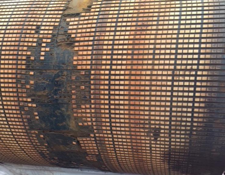
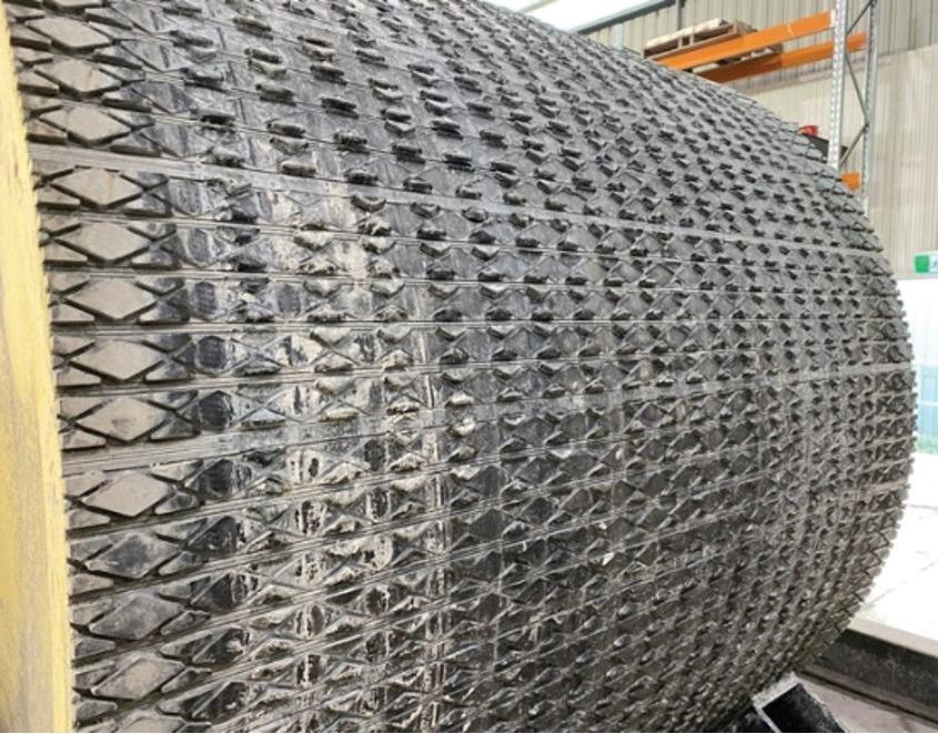
Ceramic lagging on a high-tension bend pulley began to show premature damage along the centreline of the pulley.
changes in cord path length due to cover wear or pulley contamination leads to significant changes in the load sharing between cords. Some examples are highlighted below.
High tension bend pulley: iron ore
Ceramic lagging on a high-tension bend pulley began to show premature damage along the centreline of the pulley. The installed belt exhibited cover wear along the central section of the carry side, due to wear from the bulk material. This change in belt thickness resulted in an increased stress along the centreline of the high-tension bend pulley, and subsequently failure of the ceramic bonding.
High tension bend pulley: copper
In a copper mine, signs of physical damage and delamination along the centreline of a high-tension bend pulley began to show after three months in operation. The installed belt exhibited cover wear along the central section of the carry side, resulting in increased stresses along the centreline of the high-tension bend pulley. This increase in stress lead to the increase in wear and subsequent delamination of the lagging.
Drive pulley: Gold
Upgrade of a conveyor belt in a gold mine to a higher strength, resulted in a significant increase in lagging wear, despite the same lagging being used successfully on the previous belt, and the same operating conditions of the conveyor. Drive and lagging design are all within current design specifications. While the cause of this failure is still under investigation, it is believed that an increase in stress was transferred to the lagging, resulting from the upgrade of the conveyor belt.
The existence of uneven load sharing between steel cords would likely present subtly in two ways; uneven lagging wear on the pulleys, and/or mis-tracking of the conveyor belt. This would develop with time, and without rupture or damage The ESS IPS Cleaners deliver superior belt cleaning performance and unparalleled serviceability for a variety of applications.
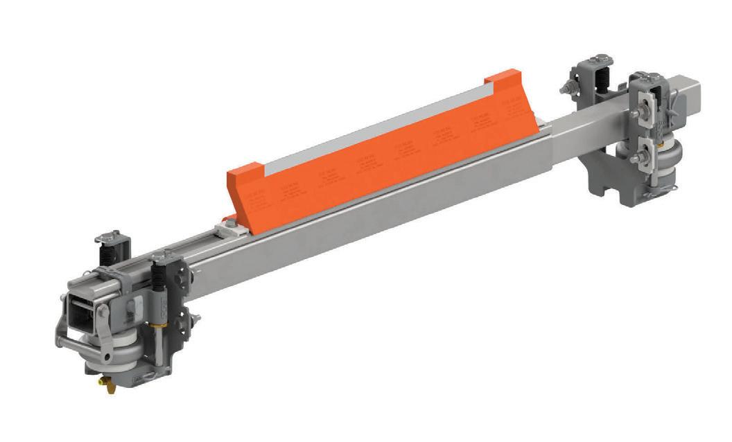
The IPS is an upgraded version of the ESS InLine 20-Ten Premium Cleaner & the original ESS InLine cleaner, which set the standard for cleaning performance combined with safety and ease of service.
Design features of the new IPS Secondary Cleaner include;
• Improved encapsulated slide design –
reduces jamming for easier service
• Stainless steel manufacture – to resist
product wear and suitable for corrosive environments
• New tensioning bracket design – increases
the cleaners sensitivity to belt movement to maintain optimal cleaning pressure and angle
• New Air and Spring Tensioner design
– interchangeable to offer flexibility as the requirements of the client changes
• Same footprint as the 20Ten Premium
InLine cleaner - as a client 20Ten Premium cleaner comes to the end of its service life a new
IPS Cleaner can be retrofitted.

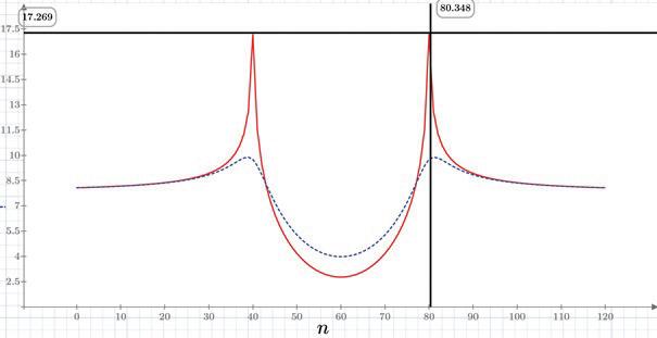
Figure 4: Tension (kN) within the steel cord cables at the point of first contact on the pulley, T1 (red line), and half-way (90°) around the drive pulley (blue line) [4].
Upgrading the conveyor belt resulted in a significant increase in lagging wear.
of individual cords, is unlikely to be detected by current belt monitoring systems. Detection of this sooner rather than later would help minimise fatigue to individual cords and splices and extend the service life of the belt.
The future of research
In response to these cases, Elastotec has partnered with the University of Newcastle to further develop the understanding of friction behaviour within a pulley contact. Experience from both companies has demonstrated that when it comes to friction of viscoelastic bodies, tests utilising static or rigid body dynamics can lead to erroneous outcomes, and in particular, curved surfaces behave differently compared to flat. To completely understand this behaviour, a full-scale test facility is currently being designed, and will be built at the University of Newcastle, with the capabilities of measuring crucial properties around the pulley circumference, and across the pulley face. Parameters such as normal load/ pressure, shear force, and belt tension are just a few that will be measured, for a given belt tension, lagging surface and angle of wrap. Tests will be conducted at installed operating tensions. Testing will be completed for a variety of lagging types, on new and used belt samples. In addition to this, used belt samples will be tested on both sides, to measure stresses around a high-tension bend pulley in contact with the carry side.
By extension, once the stress profile within the contact is understood it will then be possible to review existing lagging installations, and determine the maximum stress exhibited in these materials. This knowledge will allow a performance envelope to be defined for each lagging material and validated using the planned test facility. It will also be possible to extrapolate to the limit of allowable power transfer for a given drive design.
Concluding remarks
The inadequacy of a simple Euler friction model to predict friction behaviour around a pulley has long been known, however the extent of this misunderstanding is only currently coming to light. Beginning as a means of preventing belt slip in a drive pulley, the complications associated with a lack of understanding of the drive traction can and is leading to failures of belt covers and lagging materials.
The intent of this paper is to raise awareness of emerging issues around pulley friction, the complexity of the issue, and the failures that may result. A deeper understanding of friction and the stresses that result will allow engineered design of lagging materials and optimise lagging selection. As conveyors continue to grow in length and throughput, designers will have confidence in the lagging selection, and its performance under new and aged conditions. These topics are the subject of ongoing research.
References 1 A. Tiwari and B. N. J. Persson, “Conveyor Belt
Drive Friction: Ceramic Lego Sliding on Rubber
Belt.” PGI-1, FZ Juelich, Germany. 2 A. Harrison, “Modelling Belt Tension Around a
Drive Drum,” Bulk Solids Handl., vol. 18, no. 1, pp. 75–79, 1998. 3 P. Robinson, C. Wheeler, V. Agarwal, W.
Srinivas, and J. Guo, “Pouch conveyor drive system dynamics,” Int. J. Mech. Mater. Des., vol. 17, no. 1, pp. 187–199, 2021. 4 A. Reicks, “R&D Report - Theoretical Model to
Evaluate Belt Wear Effects on Lagging Stress.”
Overland Conveyor Company, Elastotec Pty Ltd. 5 J. M. Hedgepeth, Stress concentrations in filamentary structures. National Aeronautics and Space Administration, 1961.
SUBSCRIBE
To Australia’s only publication 100%-focused on bulk solids handling. It covers conveyors, silos, engineering, dust control, powder handling, weighing, pneumatics and much more, in industries such as mining and metals, ports and terminals, grain, fertiliser, sugar, salt, foods, milling, resins, cement and woodchips.
www.bulkhandlingreview.com VOLUME 26, ISSUE 4 | JULY/AUGUST 2021
In this issue: BULK2021 Showguide Belt cleaners and scrapers Automating bulk handling
www.bulkhandlingreview.com
VOLUME 26, ISSUE 5 | SEPTEMBER/OCTOBER 2021
In this issue: Conveyor showcase Reducing your dust emissions Choosing condition monitoring
www.bulkhandlingreview.com VOLUME 26, ISSUE 2 | MAY/JUNE 2021
In this issue: Silos and storage Are tailing dams viable? BULK2021
See the full range of fast-payback equipment at flexicon.com.au: Flexible Screw Conveyors, Tubular Cable Conveyors, Pneumatic Conveying Systems, Bulk Bag Unloaders, Bulk Bag Conditioners, Bulk Bag Fillers, Bag Dump Stations, Drum/Box/Container Tippers, Weigh Batching and Blending Systems, and Automated Plant-Wide Bulk Handling Systems II-0548 ©2020 Flexicon Corporation. Flexicon Corporation has registrations and pending applications for the trademark FLEXICON throughout the world. 4/27/20 11:38 AM DELIVERING ONE OF AUSTRALIA’S BIGGEST UNDERGROUND DOWNHILL CONVEYOR SYSTEMS Grain storage silos and conveyor systems specialistsTHE ORIGINAL LOW PROFILE FEEDER
1 year $99.00 (inc GST)
6 issues of Australian Bulk Handling Review and 1 copy of the Equipment and Services Guide 2 years $179.00 (inc GST)
Advertiser Page
Aerobelt...........................................................................51
Allied Grain Systems........................................................49
Altra Industrial Motion Australia ......................................7
Aspec Engineering...........................................................39
Astec.................................................................................43
Aurora Process Solutions................................................15
Bintech Systems..............................................................47
DSH Systems....................................................................29
Dyna Engineering............................................................31
Fenner Dunlop Conveyor Belting Australia....................13
Flexicon Corporation Australia.........................Back cover
Jenike & Johanson..........................................................37
Kinder Australia...............................................................55
Kotzur...............................................................................21
Martin Engineering..........................................................25
Mobile Conveying Services...............................................5
Nelson Silos.....................................................................57
Oli Vibrators.....................................................................53
RKM International Roller Company................................33
Schaeffler Australia.........................................................19
Schecnk Process Australia..............................................35
Sumitomo Drive Technologies .......................................41
Transmin...........................................................Front cover
Tribotech..........................................................................23
TUNRA Bulk Solids Handling Research Associates........17
Vega Australia.........................................Inside front cover
Vortex Global.....................................................................8
Reduce and Distance Plant Personnel while Boosting Output and Preventing Contamination
with automated, enclosed bulk equipment and systems from Flexicon
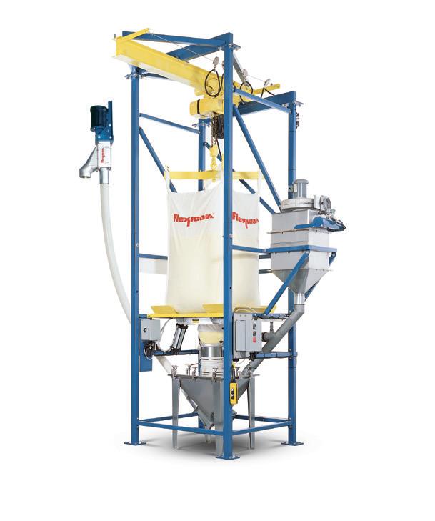
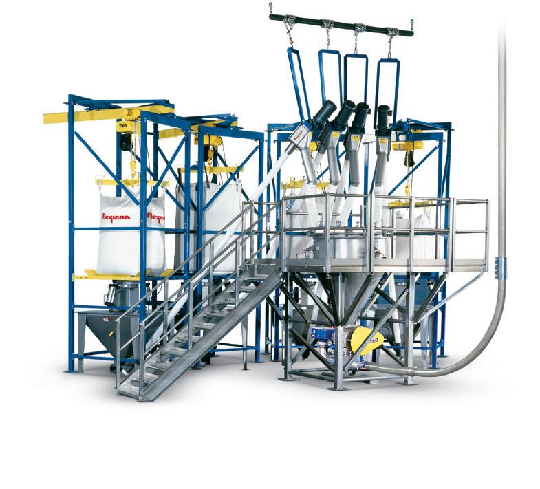
replace multiple workers dumping hand-held bags manually, while preventing contamination.
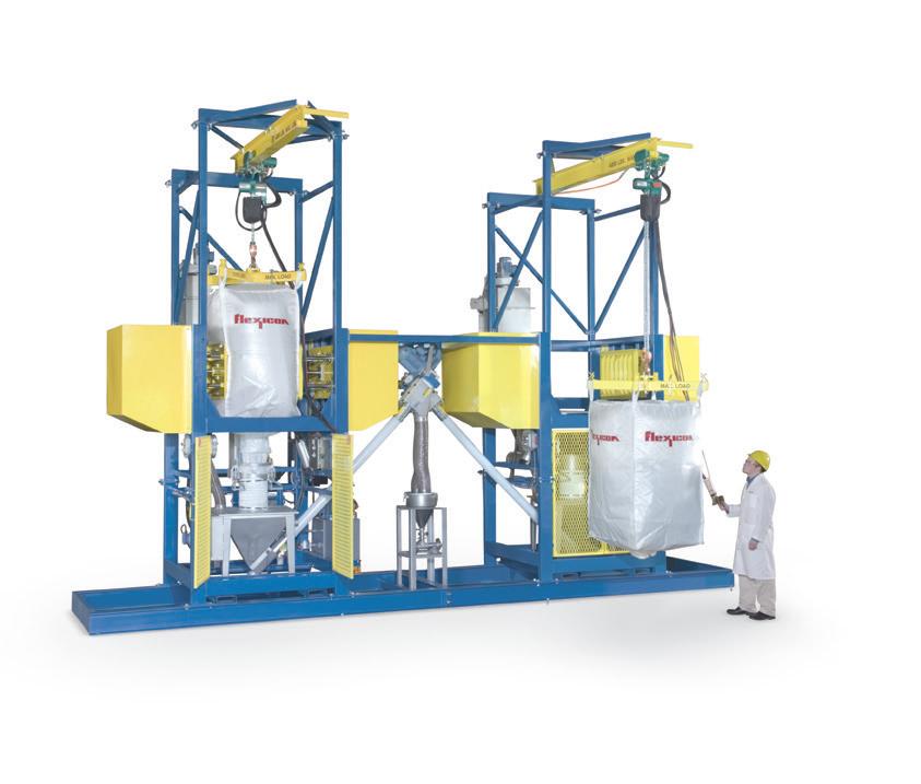
Enclosed Bulk Bag Weigh Batch
Systems feed a central weigh hopper mechanically, and remove weighed batches pneumatically, requiring labour only to attach/detach bulk bags.
Bulk Bag Discharging Systems
can loosen solidified material and meter it into liquid streams (shown), screeners, size reduction equipment and continuous blenders—automatically.
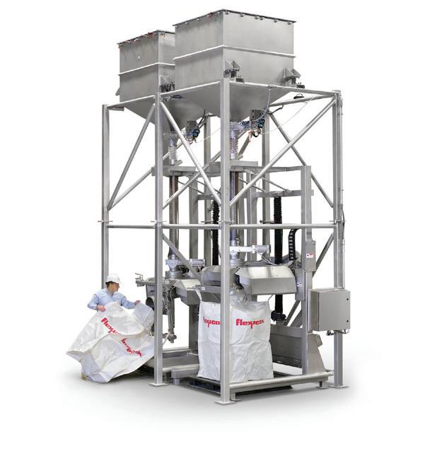
Dual SWING-DOWN® Bulk Bag Fillers
fed by weigh hoppers fill up to 40 bags per hour with only one operator connecting empty bags and one forklift removing full bags.
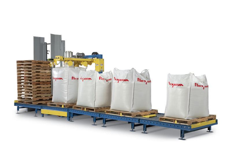
Flexicon Bulk Bag Filling Lines
automatically dispense pallets, fill bulk bags, and disconnect/accumulate filled bags, minimising operator involvement.
Flexicon automated equipment and systems can move your bulk materials at higher capacities with fewer personnel, cutting costs while distancing operators from one another.
AUSTRALIA
sales@flexicon.com.au 1 300 FLEXICON +61 (0)7 3879 4180
USA SINGAPORE INDONESIA SOUTH AFRICA UK SPAIN FRANCE GERMANY CHILE
+1 610 814 2400 +65 6778 9225 +62 81 1103 2400 +27 (0)41 453 1871 +44 (0)1227 374710 +34 930 020 509 +33 (0)7 61 36 56 12 +49 173 900 78 76 +51 2 2415 1286
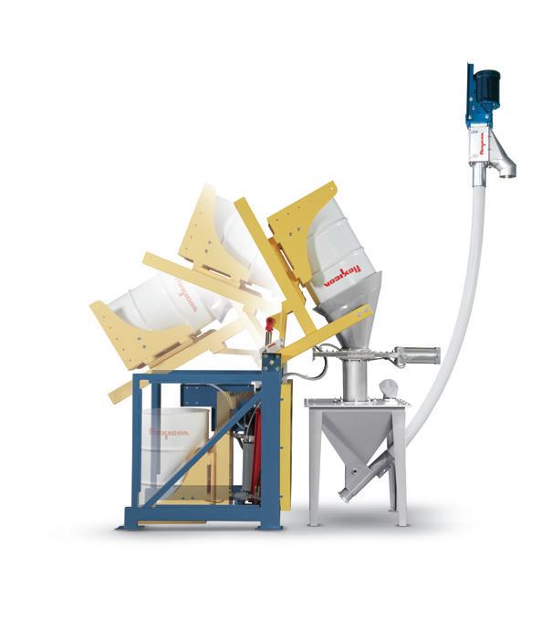
TIP-TITE® Drum/Box Tippers
seal, tip and mate a discharge cone to a gasketted hopper lid, open a slide gate and feed downstream processes— automatically and dust-free.
See the full range of fast-payback equipment at flexicon.com.au: Flexible Screw Conveyors, Tubular Cable Conveyors, Pneumatic Conveying Systems, Bulk Bag Unloaders, Bulk Bag Conditioners, Bulk Bag Fillers, Bag Dump Stations, Drum/Box/Container Tippers, Weigh Batching and Blending Systems, and Automated Plant-Wide Bulk Handling Systems


