8 minute read
TECH KNOW
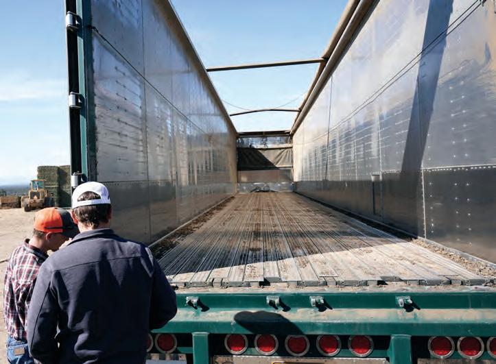
WALKING FLOOR TRAILERS
Choosing reliable equipment is key to operating an efficient fleet. Frequent breakdowns or complex maintenance requirements keep vehicles off the road, costing your business in time and money.
Keith has spent the past 50 years designing a trailer unloading system aimed at providing customers the lowest cost of ownership of any moving floor on the market.
According to Zyggy Reinoga of Keith Walking Floor Australia, the reliability of Keith’s hydraulic drive unit helps build loyalty among Keith Walking Floor customers, “The Walking Floor drive requires very little maintenance, especially when compared to the daily maintenance required to keep other systems in good working order.”
Reinoga explains that the Keith Running Floor ll drive unit was designed for the lowest total cost of ownership over the lifetime of the equipment. Interchangeable components like the cylinders and the check valves mean fewer parts are required for a fully stocked back-up inventory.
In addition, Keith systems are designed to make servicing the equipment as simple as possible. Easily accessible components cut downtime when repairs are needed. “You don’t need to break down the entire system to replace one valve.”
Maintenance requirements are also minimal. Keith recommends drivers conduct daily visual inspections of the Walking Floor system, checking hydraulic fittings, hoses, bolts and floor slats for loose connections, leaks or damage. “Drivers are in the prime position to notice small issues like loose floor bolts and fix them
before they cause any damage,” adds Reinoga.
Aside from that, implementing a basic monthly and biannual maintenance routine will help keep the Walking Floor system operating trouble-free. On a monthly basis, or after 25 operating hours, recommendations include checking the system for hydraulic leaks and making sure that the operating temperature is within acceptable range. No component should be warmer than 60° Celsius.
Retorquing the bolts that see the most movement is an important step in the monthly maintenance schedule. The three cylinders are attached to the drive unit with barrel clamps. Those bolts, along with the floor bolts should be retightened each month.
At the six-month mark, or after 150 operating hours, Keith recommends inspecting the wear areas of the drive unit and flooring components for possible replacement. Oil filters should also be changed. “If you are running clean hydraulic oil through the system, problems will be few,” says Reinoga.
Rotating the floor slats end-for-end is another procedure recommended by Keith to extend the life of the slat. If the ends of the floor slats are worn more than three-quarters of the original thickness, it is suggested to remove the slats and rotate them. “A general guide for slat rotation or replacement is after approximately 3,000 loads, depending on the material you are hauling.”
“A little regular care goes a long way with Walking Floor systems,” says Reinoga.
SCAN THE QR CODE TO FIND OUT MORE ABOUT KEITH WALKING FLOOR SYSTEMS
PRIMAAX D PIN BUSH
Hendrickson PRIMAAX heavy-duty rear suspension is inherently reliable and requires no regular maintenance other than checking fastener torque and overall inspection. However, like any system with rubber bushes, these require regular assessment and will eventually need replacement. Replacement of the D-pin bushes is a simple procedure provided the correct process is followed along with suitable equipment.
You will need a suitable portable hydraulic press and adapters. OTC make specialised PRIMAAX suspension bush replacement kits. They are available including a hydraulic pump OTC 4247 (Hendrickson 66086-204) and without the pump OTC 4246 (Hendrickson 66086-202).
WARNING: To prevent personal injury from possible breakage under pressure, do not stand in the vicinity of the tool while the D-pin is being extracted or installed. It is especially important to not stand in the direction of the hydraulic force. Pump capacity must not exceed 700 bar (10,000 psi).
DISASSEMBLY
FIGURE 01
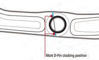
1. Mark the support beam to show the alignment of the existing D-pin. Refer
FIGURE 02
REPLACEMENT
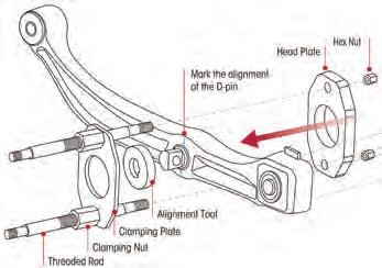
Figure 01. 3. Install the alignment tool over the D-pin and place the clamping plate over the alignment tool. Refer Figure 02. 4. Assemble the clamping nuts to the threaded rods. 5. Insert threaded rods through the upper and lower holes in the clamping plate and the head plate. Install a hex nut on the threaded rod. 6. Tighten the clamping nuts to the clamping plate. 7. Remove the alignment tool.
WARNING: To prevent personal injury, the cylinder must be fully threaded into the cylinder mounting plate.
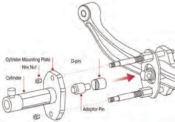
8. Thread the cylinder into the cylinder mounting plate. Refer Figure 03. 9. Install the cylinder mounting plate onto the end of the threaded rods. Adjust the clamping nuts as needed to fit the threaded rods through the holes in the cylinder mounting plate. Assemble the hex nuts on the threaded rods. Tighten the hex nuts on both ends of the threaded rods. 10. Place the D-pin adapter over the
D-pin. 11. Insert the adapter pin into the head of the cylinder. 12. Prepare the hydraulic pump for use by following the instructions provided with the pump regarding connection, venting, priming and operation. 13. Connect the hydraulic hose from the hydraulic pump to the cylinder. 14. Operate the pump to extend the cylinder piston and apply pressure to push the D-pin out of the support beam. ASSEMBLY
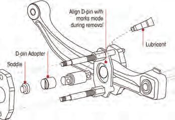
1. Clean and lubricate the entire surface of the inside diameter of the support arm and D-pin outer metal sleeve with chassis grease. Refer
Figure 04. 2. Insert the saddle into the head of the cylinder. 3. Assemble the new D-pin and the
D-pin adapter as shown. Align the line in the D-pin adapter with the alignment marks made during the removal procedure. 4. Operate the pump to extend the cylinder piston and apply enough pressure to hold the tool and components. Check the alignment of the D-pin. The centreline of the
D-pin must be aligned with the centreline of the inside diameter of the support beam. 5. Operate the pump to apply pressure to install the D-pin completely into the support beam.
For more details refer to technical bulletin PRIMAAX maintenance and service procedures, 97117-212, which is available on the Hendrickson Australia website.
NEEDEDCHANGES
TO ROAD TRAIN NOTICE
The development of a national notice for road trains has great potential, and the National Heavy Vehicle Regulator should be commended for taking the task on, reckons Bob Woodward, Australian Trucking Association Chief Engineer.
The release of the draft Heavy Vehicle National Law, National Class 3 Road Train Prime Mover Mass and Dimension Exemption Notice 2021 (No.1) shows that changes are needed to achieve this potential. Resolving technical issues with the notice will be key to realising the intended productivity benefits.
Three key technical issues stand out: • Steer axle mass up to 7.1 tonnes • Dimensions up to 27 metres, with internal constraints • Livestock and volumetric loading.
Many people are quick to focus on the steer mass and the overall length, but there are limits within the detail.
STEER AXLE MASS The National Class 3 Road Train Prime Mover Mass and Dimension Exemption Notice 2021 Operator’s Guide sets out:
Section 11 Condition (3): An eligible vehicle that is a road train prime mover towing two compliant trailers as a B-double combination may exceed the mass limits set out in Table 3 of Part 2 of Schedule 1 of the National Regulation by 1.1t, on condition that the excess is caused by the steer axle mass limits in section 10.
Some consignors are assuming that all B-doubles consisting of a road train ‘registered’ prime mover are eligible for GML at 63.6tonnes (62.5 plus 1.1) and CML at 65.6tonnes (62.5 plus 1.1 plus 2.0).
WELL, THIS ISN’T NECESSARILY SO! To be eligible for 7.1tonnes the steer axle must meet technical specifications.
There is more to this than just tyre section width.
The steer axle mass is limited by technical and legislative requirements. This includes tyre section width and tyre load index (minimum tyre section width 375mm), steer axle load rating, this may be reduced by tyre/rim offset factors and steer axle suspension load rating.
The allowable mass limit for the steer axle assembly is the lesser of ALL these constraints. For example: • Tyre/s: 385/65R22.5, 158L, Load rating (at maximum ADR cold inflation pressure of 825kPa) 8270kgs. • Axle: ABC6600 GALR (gross axle load rating) 6600kgs • Suspension: XYZ670, GALR 6700kgs
The maximum technical limit for the example steer axle is 6600kgs.
The equipment technical requirement applies to all road train prime movers regardless of combination configuration.
DIMENSIONS The use of a ‘qualifying’ road train prime mover used in a B-double raises a number of issues. Whilst the overall length of 27metres seems to be well understood, the kingpin to rear dimension maximum of 20.6metres remains, along with a minimum of 18metres from the first driven axle to the last axle of the rear trailer triaxle for full GML mass.
In Queensland the prime mover also must have a minimum theoretical wheelbase of 5.0 metres, and whilst the internal axle spacing rules for a B-double remain, in Queensland there are minimums on clear space (the X and Y rule) X ≥ 5.35 and Y ≥ 5.5
LIVESTOCK VOLUMETRIC LOADING Volumetric loading is not permitted under this Notice.
NATIONAL NOTICE The notice does not give us national uniformity. It sounds more like the rail system of the past, Queensland 3’6”; New South Wales 4’8½”; Victoria 5’3”; South Australia 3’6”. But national consistency risks being reduced to being consistently different at each border crossing.
Whilst the objective of this notice is commendable, it risks falling apart on these technical issues which will impact the practical application by industry.
SCAN THE QR CODE TO FIND MORE TECH DATA FROM THE ATA


