

Pump Industry Australia Incorporated
Kevin Wilson – Secretary PO Box 55, Stuarts Point NSW 2441 Australia
Ph/Fax: (02) 6569 0160 pumpsaustralia@bigpond.com
Ron Astall – President United Pumps Australia & Astech Consulting Services
John Inkster – Vice President Brown Brothers Engineers
Mike Bauer - Councillor Dynapumps
Geoff Harvey - Councillor Davey Products Pty Ltd
Tony Kersten - Councillor Grundfos Pumps Pty Ltd
John Link – Councillor Link Pumps
Martin O’Connor – Councillor KSB Australia
Alan Rowan – Councillor Life Member
Keith Sanders – Councillor Australian Industrial Marketing & Life Member
President’s welcome
The importance of energy efficiency is obvious. We already have in place “MEPS” (Minimum Energy Performance Standards) for electric motors, MEPS for fans is not far away and MEPS is in the planning stage for centrifugal pumps. Sustainability Victoria is the driving force behind these initiatives and those of you who attended our energy efficiency seminars and our recent PIA Exhibition and seminar last October should be well aware of these developments.
So from a pumping perspective, we already have mandatory electric motor efficiency standards, and similar standards for pumps are on the way.
Does this mean job done? Not even close!
Aiming for more efficient pumps is a no-brainer, but pumps - particularly centrifugal pumps - are pretty unique in that their power consumption is hugely influenced by the system into which they are installed. Unlike a stand alone appliance that may receive an energy rating, pumps are slaves to the system and to the specifier. In his presentation to PIA last October, Sustainability Victoria’s Ian McNicol correctly highlighted that pumps are only one facet of total pumping system efficiency.
A poorly designed system incorporating an efficient pump is still a poor system. A well designed system with an efficient but incorrectly sized or throttled pump is still a poor system.
The real issue is minimising power consumption. A friend of mine was designing a transfer pumping system and asked my advice on pump selection. Originally he wanted to limit himself to 50mm poly pipe because this was cheaper. This would have meant around a 200kW pump for the pipeline length involved. Of course common sense intervened and we found a compromise with 100mm pipe
requiring only a 30kW pump. His annual running costs were obviously much lower and in this instance the capital cost was also better. Interestingly, because larger pumps are typically more efficient than smaller pumps, the 200kW unit would have had a better pump efficiency than the smaller 30kW unit.
The point of this example is that pump efficiency is far less important than the overall system efficiency. Again, the real issue is minimising power consumption.
This brings me to the excellent presentation from John Macdonald from AusIndustry at our February General Meeting; in particular; the Clean Technology Investment Program.
This program is an $800 million competitive, merit-based grants program that supports Australian manufacturers to invest in energy efficient capital equipment and low emission technologies, processes and products. The program will provide funding over a seven year period from 2011-12 to 2017-18.
As pumps are often responsible for the bulk of industrial energy consumption, this program could be of benefit to many pump users and would potentially assist in covering upgrade costs for inefficient or worn pumping systems. I encourage pump users to investigate this program and the pump industry to let their customers know that this is available. http://www.ausindustry.gov.au/ programs/CleanTechnology/CleanTechnologyInvestment/Pages/default.aspx
The challenge for us all is to encourage better system design and to correctly specify the most efficient pumps available.
Ron Astall President, Pump Industry Association
1
PUMP INDUSTRY
Editor’s welcome pumpindustry
This magazine is published by Monkey Media in co-operation with the Pump Industry Association (PIA). The views contained herein are not necessarily the views of either the publisher or the PIA. Neither the publisher nor the PIA takes responsibility for any claims made by advertisers. All communication should be directed to the publisher.
The publisher welcomes contributions to the magazine. All contributions must comply with the publisher’s editorial policy which follows. By providing content to the publisher, you authorise the publisher to reproduce that content either in its original form, or edited, or combined with other content in any of its publications and in any format at the publishers discretion.
Published by Monkey Media Enterprises

ABN: 36 426 734 954
GPO Box 93, Melbourne VIC 3001
P: (03) 9440 5721
F: (03) 8456 6720 monkeymedia.net.au info@monkeymedia.net.au pumpindustry.com.au magazine@pumpindustry.com.au
Design by Linda Tucker
Happy Places Design www.happyplaces.com.au
ISSN: 2201-0270
Welcome to the third edition of Pump Industry magazine. I’m delighted to say that the strong growth trajectory for the magazine has continued with this issue. We’ve gone from 48 pages in issue 1; 56 in issue 2 and the edition you are now holding in your hands, or browsing online, is 72 pages - and there has been a corresponding increase in advertising take up from issue to issue as well.
Particularly pleasing has been our strong growth online, with hundreds of unique visitors every week and web traffic continuing to increase. We’ve noticed that people are using hundreds of different search terms to find us, ranging from ‘api pumps’ to ‘zinc slurry pumps’ and everything in between. Usually, they are not looking for us at all, but are pump professionals seeking out information to help them do their job better.
Inspired by this, we are working to ensure that pump users who come across the site can find what they are looking for, so we are creating special new mini-sites, called channels, within the website, focussed on particular issues. Some of the first channels we are rolling out include;
• Pumping LNG
• Pumps in building services
• Mine dewatering
• Reliability, and
• Motors and drives with plenty more to come after that. These ‘websites within a website’ will include their own email newsletters to which readers can specifically sign up and exclusive sponsorship options for related companies.

Our readers are becoming increasingly sophisticated in the way they consume information. I’ve been told by many readers that they enjoy being able to access Pump Industry in a variety of ways; they love to get the print issue and will savour taking some time out to read it in-depth, then may pass it round to colleagues or keep in on hand on their desk for months. But they also enjoy being able to access information at any time on the website and to be able to search through all our content at once. And as well as getting their news regularly from the email newsletter, savvy readers are also getting our content daily through social channels such as Twitter and LinkedIN.
This ties in perfectly with the feedback I’ve get getting from advertisers, who are looking for integrated solutions to get their message out to the pump industry, and end users of pumps. So we will continue to expand our offerings and ensure that as well as print advertising, companies can also reach our readers through a range of other options including; online advertising; providing useful content to drive traffic to their websites and enhance their SEO and we will also work with companies to make use of the social media marketing opportunities available.
I appreciate all the feedback I’ve got so far, and if you’ve got any ideas, I encourage you to drop me a line.
But that’s enough about us and the business of publishing, please now enjoy 70 further pages, all about pumps!
Chris Bland Publisher and Editor
PUMP INDUSTRY 2
Inside Sydney Water: in-depth interview MAY 2013 ISSUE 3 Reliability getting the best out of your pump systems Building services pump selection in the HVAC industry Seals or sealless pumps? Australia’s Number 1
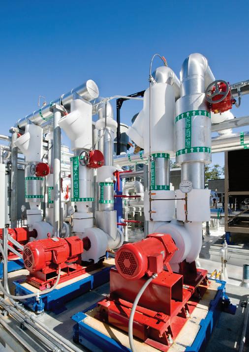
Cover shows a typical rooftop pump system used in HVAC applications.


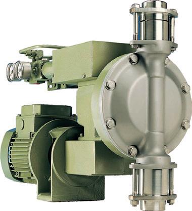
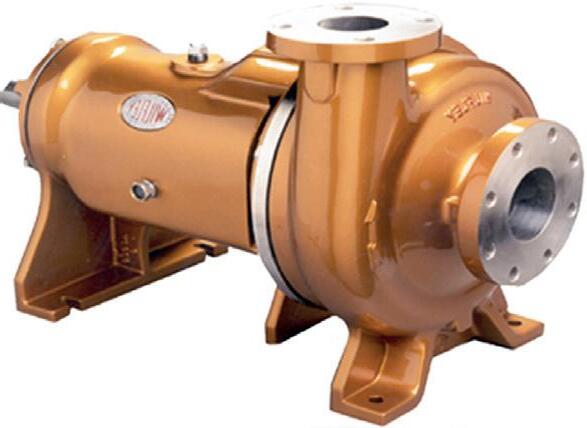

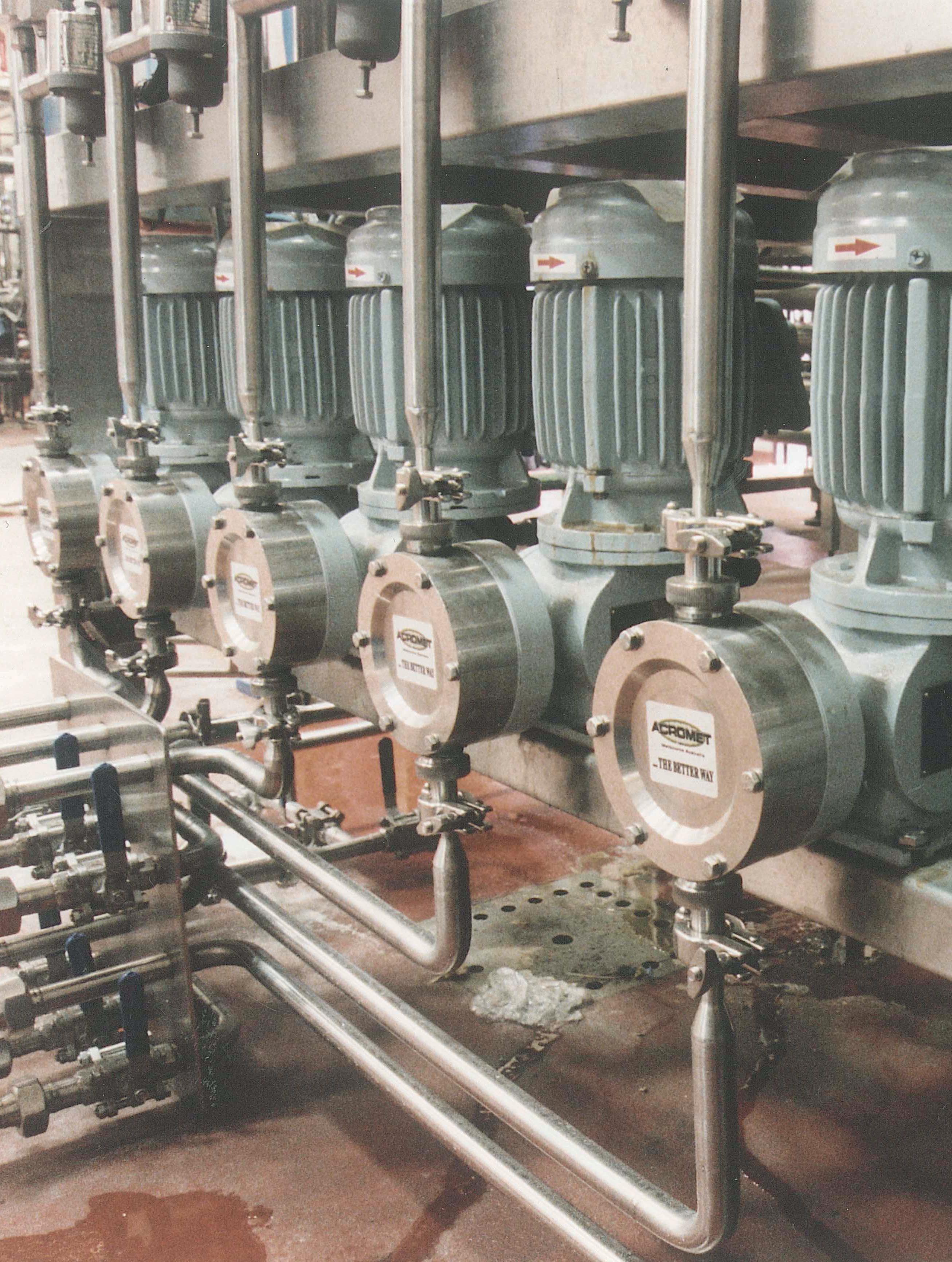
Celebrating 50 years of Service To Australian Industry P O Box 1105, Clayton South, Vic 3169 www.acromet.com.au Email: chemex@acromet.com.au Ph: (03) 9544 7333 Fax: (03) 9543 6706 Robust Pumps Reliable Service Total Commitment Chemical Metering and Process Transfer Pumps
pumpindustry
MAIN FEATURES
Reliability
Fighting black oil and understanding bearing housing upgrade opportunities - by Heinz Bloch......................................................20
Oil Mist lubrication by Don Ehlert and Marty Williams................26
Thermodynamic performance testing and monitoring by Malcolm Robertson...................................................................30
Is your pump reliability in the balance by Christopher Morse....33
Interview: Inside Sydney Water
In this ongoing interview series, we talk in-depth with the end users of pumps across a range of industries and applications. This edition we interview Bruce Maunder, Sydney Water Senior Specialist in Pumping Systems, to get an inside view of Sydney Water.
The Australian office building market...........................................50
Pumps key to Darling Quarter’s sustainable success.................52
Centrifugal pump selection in the HVAC industry........................54
Let’s play the Mechanical Seal Game
by
Larry Bachus, aka The Pump Guy
OK kids, let’s play the Mechanical Seal Game. To play this game we need one industrial process plant. A paper mill, oil refinery, thermo-electric power plant, pharmaceutical/chemical plant, or municipal water plant will do.
PUMP PIONEERS
Bruce Ellis
In the ongoing Pump Pioneer series, Chris Bland catches up with Bruce Ellis who started in the industry almost 50 years ago and whose career included many years as Managing Director of Mono Pumps


CONTENTS
34
20
56
Building Services 50
43 46
60
President’s welcome...................................1 Editor’s welcome.........................................2 Contracts awarded......................................6 News briefs..................................................8 Calendar of events....................................12 Index 72
Modernising an Australian icon
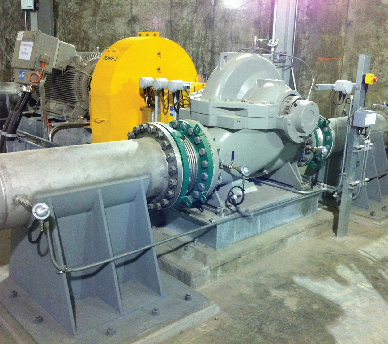
The Snowy Mountains Hydro-electric Scheme is one of Australia’s most iconic engineering achievements. The scheme is now undergoing a $400 million modernisation program. The program is introducing advanced controls and protection systems technology across the entire Scheme.
Innovation for SA water pumping station
Paringa is a small town in the Riverland area of South Australia famous for its vineyards, almond, citrus and stone fruit orchards. Over the last five years, the region has been subject to strict water restrictions imposed by drought conditions.
Local capability key to emergency mine dewatering
In June 2012 Gippsland in Eastern Victoria faced some of the worst floods in recent memory. On June 6, the Morwell River dramatically burst its banks, sending floodwaters into the Yallourn open cut coal mine, damaging a coal conveyor and slowing production, then two weeks later, the mine flooded again.
Gosford council’s sewage pump station upgrade program
Gosford City Council, on the New South Wales Central Coast, is currently investing between five and seven million dollars each year to improve the performance of many of its 185 sewage pump stations. Since 2009 over 40 of its ageing pump stations have been completely upgraded, refurbished or seen their pumps replaced. 46
using air valves
48
In our environmentally sensitive world, the need for air release from liquid transfer systems to improve system efficiency is gaining momentum.
Understanding pump curves
Centrifugal pumps are frequently operated in parallel to achieve higher system flows, to enhance system flexibility or to provide greater pump redundancy and hence better system availability.
A glossary of pump terms, from A-K
Pump School 69
PROJECTS
66
TECHNICAL
11 31 17
News
Crossley.....................................................11
PIA Member
Welling &
Regal Beloit................................................................12 Xylem...........................................................................14
Acromet.......................................................................16 Emtivac.......................................................................17
Pump Systems Ltd...............18 Product showcase Fire Equipment Australia..........................................59 CONTENTS 44
New member profile:
40
Saving energy
62
CONTRACTS
OIL & GAS
Wood Group PSN awarded Caltex contract extension
Wood Group PSN has secured a contract extension from Caltex to deliver integrated maintenance services at its two Australian refineries – Lytton in Brisbane and Kurnell in Sydney. Effective from June 2013, the $45 million, 18 month contract marks the continuation of a three year contract first awarded to WGPSN in 2010.
Osmoflo to provide off-shore desalination for Ichthys
Contracts for the provision of shipmounted plants which will supply potable and process water to crews involved
Correction
In the February 2013 edition, an incorrect image was used on page 47 illustrating typical low emissions packing for rotary style control valves. The correct image is provided below.

in the recovery of liquefied natural gas (LNG) and hydrocarbons from the Ichthys field in the Timor Sea have been awarded to leading Australian desalination specialist, Osmoflo.
Leighton Contractors awarded Ichthys onshore LNG contract
Leighton Contractors’ Services Division has been awarded a four year, $280 million operations and maintenance contract by JKC Australia LNG (JKC) for the Temporary Site Facilities Works at Blaydin Point, Darwin, Northern Territory.
AusGroup awarded Allseas contract for Wheatstone LNG
AGC Industries has been awarded a supply and fabrication contract for offshore pipeline and subsea construction by Allseas Construction Contractors Australia as part of the Chevron-operated Wheatstone Project.
GE awarded $620 million services contract for QGC
GE Oil & Gas has received a US$620 million, 22-year contractual service agreement (CSA) to provide a broad range of advanced technology services for QGC’s Queensland Curtis LNG (QCLNG) plant.
ABB wins Ichthys order
ABB has been appointed the main electrical contractor (MEC) for a new semisubmersible central processing facility (CPF) at the Ichthys oil and gas field in the Timor Sea off Western Australia. The order is valued at $15 million.
Featured project
More pump contracts awarded on Ichthys
Inpex has recently awarded further pump contracts for both the offshore CPF and FPSO and the onshore gas processing plant on the Ichthys LNG project.
Renroc Group (Pumps & Engineering) was awarded a contract for a number of API 610 Centrifugal Pumps for the Central Processing Facility (CPF) and the FPSO. The scope of supply for the orders to Renroc includes the design, manufacture and installation of pump packages on the CPF and FPSO. The pumps will be delivered in 2013.
The contract for two sewage pumps has been awarded to Ruhrpump Australia and includes the design, manufacturing, testing, certification painting, documentation and operation spares, preservation, packing and transportation of 12 submerged motor sewage pumps with a capacity of 14m3 and a head of 19 m and 12 submerged motor sewage pumps with a capacity of 25 m3 and a head of 27m .
These two wins for Australian companies stand in contrast to the number of pump contracts being awarded to international suppliers.
The project also awarded the design, manufacturing, testing, certification painting, documentation and operation spares, preservation, packing and transportation for various non API “Vertical Centrifugal Type Pump” to Flowserve GB.

• Motor or wall mountable
• Fully programmable on site
• Software specifically designed for pump operation, control and protection
• High level hardware design
• More flexibility and cost savings
• Energy savings up to 70%
• Simple mounting “clip and work”
• Multi-pump capability up to 8 pumps

6
Melbourne: (03) 9793 9999 Sydney: (02) 9671 3666 Brisbane: (07) 3200 6488 Email: info@brownbros.com.au Web: www.brownbros.com.au
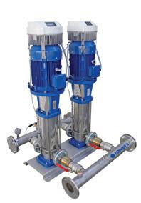
HYDROVAR, the modern variable speed pump drive taking pumping to a new level of flexibility and efficiency. Call us today for a Hydrovar technical brochure to see how we can deliver your pumping solutions. DELIVERING PUMPING SOLUTIONS 04/13
RECENT
AND TENDERS AWARDED
MINING
Monadelphous Iron Ore contract Engineering group Monadelphous has been awarded a major iron ore contract for Rio Tinto’s Western Turner Brockman Project in the Pilbara region of Western Australia. The contract is for the supply and installation of structural, mechanical, piping, electrical and instrumentation works for the construction of the Western Turner Brockman iron ore plant.
EPC contract awarded for Carosue Dam Tertiary Crushing
GR Engineering has been awarded a contract from Saracen for the engineering, procurement and construction (EPC) contract for the Carosue Dam Tertiary Crushing Project near Kalgoorlie in Western Australia.
Ausenco to manage Newcrest projects
Ausenco Limited has secured an initial three-year contract to manage a portfolio of projects at Newcrest Mining Limited’s Lihir gold operation in Papua New Guinea. Ausenco will provide project delivery services to support ongoing capital projects, with the services delivered under an EPCM contract working closely with the Newcrest team.
Macmahon awarded largest ever mining contract
Macmahon Holdings Ltd has been awarded its largest single mining contract, worth $1.8 billion, to deliver open cut mining services as part of the Christmas Creek Mine expansion for Fortescue Metals Group Ltd.
WATER
Tenix awarded Nambour STP Upgrade
Tenix has been awarded a $40 million contract by Unitywater to design, construct and commission a major upgrade to the Nambour Sewage Treatment Plant (STP).
Gosford Council awards pump station tender
Gosford Council has awarded the tender for the refurbishment of a sewer pump station at Hardys Bay. The tender was awarded to local company Carey Constructions Pty Ltd, who beat out four other tenderers.
ONLINE
Keep up-to-date with all the latest news
You can get all the latest news daily online at the pump industry website. Sign up for the free newsletter so you don’t miss anything.
Get the latest contracts and tenders awarded at; pumpindustry.com.au/category/awarded/
See the latest open tenders at; pumpindustry.com.au/category/tenders/
Sign up for the free online news at; pumpindustry.com.au/subscribe/
Or just visit the home page and follow the menu options.
Got any news?
If you have any news, such as people movements, new staff, contracts awarded, projects completed etc, please submit to the editor at

Inpro-Seal compound labyrinth bearing seals and air purged product


magazine@pumpindustry.com.au
Full details at www.pumpindustry.com.au
seals. Manufactured in
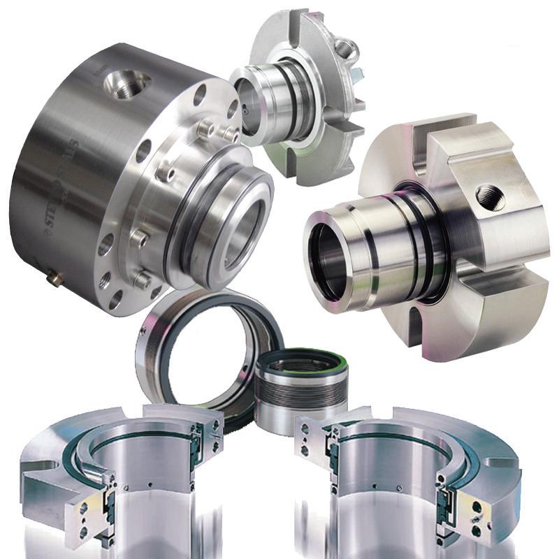
suit your application. Stevco are authorised agents for We offer a comprehensive range of mechanical seals from simple pusher styles to single, double and split cartridges, and custom engineered sealing systems. We supply seals for pumps, mixers & reactors and for duties including water, chemicals, hydrocarbons, pharmaceutical, sewerage, paper pulp and food & beverage. Contact us to discuss your sealing needs. Melbourne (03) 9408 3875 vicsales@stevco.com.au www.stevcovic.com.au sealing news sealing news Mechanical Seal Solutions Available from... 7
high quality bronze or stainless steel to
Sterling Pumps
Sterling Pumps has moved, the new facility incorporates new pump manufacture, pump repair and submersible motors rewind. Capacity is increased with four CNC lathes and machining centres, and a fabrication bay that includes robot welding. A 10 ton overhead crane services the full length of the workshop including the test bay.
The test bay is designed to service submersible pumps and vertical pumps with a 15m deep 2m diameter pit, end suction pumps are serviced by surface tank water. They have 300kw available on site which can be expanded to 1Mw with additional generator power.
New address:
Sterling Pumps Pty Ltd, 14 Sharnet Circuit, Pakenham, VIC 3810
Ph: (03) 9729 5044
Pump Doctor
Pump Doctor has moved to new premises located at;
88 Wedgewood Road, Hallam VIC 3803
New Ph: (03) 9796 5001
New fax: (03) 9796 3499
Power Pumps & Engineering
Power Pumps have opened a branch in QLD and have appointed Malcolm Maxwell as General Manager. The new address is;
Unit 5, 35 Notar Drive Ormeau QLD 4207
Grundfos buys BKB
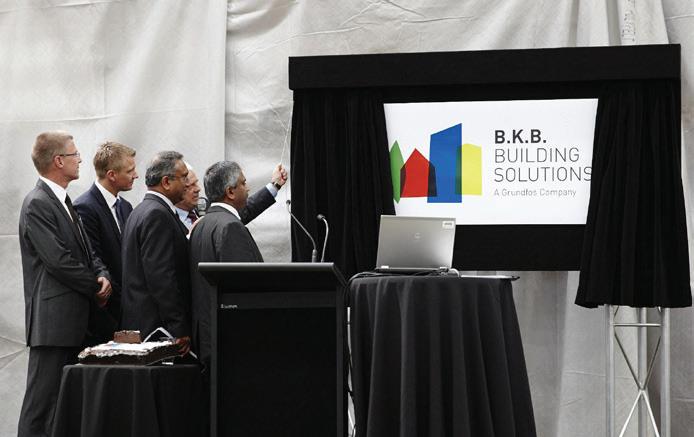
Grundfos has announced that they will acquire long term local Australian partner, B.K.B. Pumps & Tanks Pty Ltd.
The new business will merge the resources of B.K.B. Pumps and Tanks Pty Ltd with Grundfos’ Australian Commercial Building Services (CBS) team to create a new entity with national reach and industry leading capabilities and resources. The move will further strengthen Grundfos’ position in the Australian commercial buildings market.
The new entity will be called B.K.B. Building Solutions Pty Ltd (B.K.B.). B.K.B. will operate independently to Grundfos Pumps, with its own Management Team and Board of Directors. The two existing major shareholders of B.K.B. Pumps & Tanks Pty Ltd, Mr Bala and Mr Jeya Thuraisingam, will remain part of the B.K.B. Management Team as General and Deputy General Managers respectively, allowing the company to benefit from their vast experience within the industry.
Grundfos separately announced they will be supporting and selling the DAB brand in Australia and New Zealand. The DAB brand has been owned by the Grundfos Group for over 15 years and this change is seen a natural development.
New conditioning monitoring book from Ray Beebe
A new book by Ray Beebe, ‘Steam Turbine Performance and Condition Monitoring‘ is now available.
Written for the plant engineer, this book shows how to apply condition monitoring by performance analysis to steam turbines. Its aim is to assist to assist with performance problem solving and in decision making on steam turbine maintenance.
With a foreword by distinguished turbomachinery engineer Heinz Bloch, this book should be owned by every power plant engineer and is a worthy companion to Ray’s previous two books Machine condition monitoring (1988, rev 2009) and Predictive maintenance of pumps using condition monitoring (2004).
The book is available from the reliabilityweb.com bookstore.



8
AUSTRALIA UNITED PUMPS AUSTRALIA ISO 9001 CERTIFIED AS2417 ISO9906 API 610 Hydraulic Institute Performance Testing Inspection and trouble-shooting Case build up and re-machining Axial split case facing and reboring Axial thrust balancing Shaft and bearing upgrades Mechanical Seal upgrades to API 682 Custom Spare Parts Rotating Element balancing ASME & AS1210 qualified welding Hydrostatic Testing 31 Western Avenue, Sunshine, Victoria 3020 Phone: +613 9312 6566 Fax: +613 9312 6371 Email: unitedpumps@unitedpumps.com.au http://www.unitedpumps.com.au/ Efficiency Improvement Reconditioning Restore Clearances Re-Engineering Repair, Re-Manufacture For ALL types of Centrifugal Pumps NEWS BRIEFS - Keep up-to-date at www.pumpindustry.com.au Office
moves


John Weaver to head Xylem Water Systems Australasia
Widely experienced water industry professional John Weaver has taken up a new appointment as General Manager for Australia and New Zealand of the Applied Water Systems Division of international water business Xylem Water Systems Australia Pty Ltd.
He is based at the company’s headquarters in Mentone in Melbourne’s south.
John has had almost thirty years of experience in senior marketing and management roles with the last fifteen years engaged with leading Australian water businesses.
“I look forward to renewing contact with the many people in the water products sector that I have met and dealt with in my career in the industry” John says.

John Weaver’s contact details are care of Xylem Water System Australia Pty Ltd Unit 3/1 Federation Way Chifley Business Park Mentone 3194. Telephone 03 9551 7333 or 0438 770 716 or email john.weaver@xyleminc.com.
Update on water industry initiatives
By R N (Bob) Herbert AM
As the Australian Government’s Water Supplier Advocate, I have been appointed by the Minister for Industry and Innovation to promote capable and competitive Australian firms and increase their ability to win more work in the water sector.

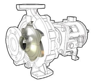
Fifty years ago, we changed the direction of the industry Literally.
In partnership with waterAUSTRALIA, I am leading Water Industry Capability Teams. There are over 320 members in these Teams, working together to market their offerings and increase their access to customers through targeted showcasing, trade shows and international water missions.
Under the Australian Water Supplier Compact agreement, I am also working with waterAUSTRALIA, the Water Services Association of Australia (WSAA) and the Industry Capability Network (ICN) to address barriers and increase suppliers’ access to opportunities in the urban water sector. Initiatives under the Compact are already underway including showcases of energy efficient and sustainable solutions to the water utilities to help them address some of their most pressing challenges and, in-turn provide valuable opportunities for capable Australian firms.
Turning to the international market, water missions to the US and Singapore over 2011 and 2012 have generated over 210 million in new leads. As a result of this success, I will be working closely with Austrade and waterAUSTRALIA to lead a trade mission of Australian water suppliers to China in June this year to promote how Australian innovation can help solve China’s water management challenges.
There is no better time to take advantage of the wide range of initiatives in place to support Australian industry. I encourage all Australian firms to be involved and have a say in the future direction of the water sector.
For more information about the Capability Team’s members, please visit directory.wateraustralia.org/
10 NEWS BRIEFS - Keep up-to-date at www.pumpindustry.com.au
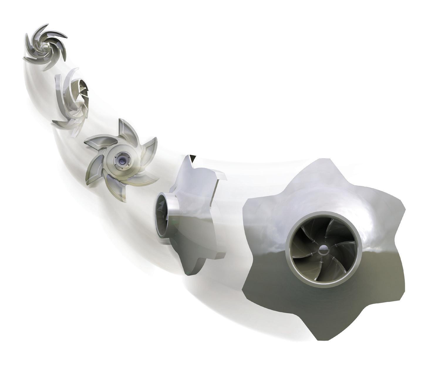
Experience In Motion flowserve.com/rvimpeller In 1962, Flowserve introduced the Durco® reverse vane impeller and forever changed the chemical process pump landscape. Its revolutionary design moved the wear surface from the casing to the rear cover This change had huge implications on the pump’s per formance, reliability and total cost of ownership, and has made the Durco Mark 3™ pump a favorite of leading chemical processors the world over The Durco reverse vane impeller is still impacting the industr y today with the Durco Mark 3 ANSI/ASME pump and the newly released Durco Mark 3 ISO chemical process pump See how at www.flowser ve com/r vimpeller For Enquiries, please contact telephone number 1300Flowserve or email to Pumpsales_Australia@flowserve.com
New lease of life for Lister Petter
You could have been forgiven for thinking that Lister Petter had gone out of business, and for a while there it was looking like it might, but for a couple British Industrialists who had the foresight to purchase the company with a view to returning it to its former glory.
One part of that plan was to establish an Oceania Regional Office within the region and it was decided that New Zealand was the place. That done Lister Petter set about a review of their distributors worldwide, that review found that whilst Australia was once a Lister Petter heartland many new players had entered the market and the Lister product had lost some of its glory.
In August 2009 Melbourne based company Welling & Crossley were appointed as the new Lister Petter distributor in Australia. Welling & Crossley are a well known manufacturer and distributor of Generating Sets around the country and a big time user of Diesel Engines. Their national distribution networks gave an immediate new market to the Lister Petter product and with the appointment of Mike Edwards (formerly having worked with both of the market leading brands
of small Japanese engines) as National Sales Manager for the new Lister Petter division everything was in place.
“I’ve spent most of my working career putting these guys out of business, I guess it’s Karma that I’m now heading it up and re-establishing the brand,” says Mike.
Welling & Crossley believes there is still a place in the market for a solidly built, hardworking, old fashioned diesel engine in Australia. Many of the recent comers and larger companies have been obsessed with emissions controls and making engines for the USA and European markets, but here in Australia we still use diesel engines in the outback, hundreds of kilometers from nowhere, and the need for reliability is paramount. And Lister Petter “doesn’t make throw away engines, you can rebuild them more
than once and more importantly you can afford to!” says Mike.
That’s not to say Welling & Crossley haven’t added a little technology to the old Lister Petter reliability, they are fitting them with state of the art Murphy irrigation control gear and with their own brand of fully programmable generator control gear. You can make them start or stop anyway you like.
Welling & Crossley are offering a full range of both Air Cooled and Water cooled Engines, Generating Sets, Fire Pump Engines and purpose built generators for Electric Submersible Bore Pumps and Center Pivot Irrigators.
For more information on the Lister Petter range contact Mike Edwards at Welling & Crossley on 1300 524 485 or email


11
medwards@wellcross.com.au.
PIA MEMBER NEWS
Who is Regal Beloit?
Regal Beloit Corporation is a leading manufacturer of electric motors, mechanical and electrical motion controls and power generation products serving markets throughout the world. Regal Beloit is headquartered in Beloit, Wisconsin, and has manufacturing, sales and service facilities throughout the United States, Canada, Mexico, Europe and Asia.
Regal Australia brings together the strength and experience of three of Australia’s leading suppliers of engineered industrial products. CMG, OBA and Transmission Australia are now in a position to offer industry an unparalleled range of products under the Regal Australia banner.
Their products are efficient and innovative; they conform to Australian design, performance and engineering standards. Regal Australia sources products from Regal manufacturing facilities and
represents some of the world’s leading industrial manufactures.
Regal Australia embraces the company core values of Integrity, High Energy and Performance and has adopted the initiatives of customer care, globalization, innovation, sustainability and simplification.
The company business statement is that “We convert power into motion to help the world run more efficiently” has direct links to our core values and initiatives.

Event Calendar
PIA Events
PIA General Meeting 14 May 2013 – Adelaide
PIA Fire Pump standards seminar 15 May 2013 – Adelaide
PIA General Meetings 13 August 2013 - Sydney 12 November 2013 (AGM)– Melbourne
For more information or to register for PIA events, visit pumps.asn.au or email pumpsaustralia@bigpond.com
Other Events
OzWater
Perth 7-9 May 2013 www.ozwater.org
Auspack Plus
Sydney 7 - 10 May 2013 www.auspackplus.com.au
National Manufacturing Week
Melbourne 7-10 May 2013 www.nationalmanufacturingweek.com.au
APPEA
Brisbane 26-29 May, 2013 www.appea.com.au
PACIA
Melbourne 4-6 June 2013 www.pacia.org.au/events/
WIOA Queensland
Gold Coast 5-6 June, 2013 www.wioa.org.au
Pumps and Compressors
Perth 25-26 June, 2013 www.idc-online.com/
IPWEA
Darwin 11-15 August, 2013 www.ipwea.org.au
WIOA Victoria
Bendigo 4-5 September, 2013 www.wioa.org.au


12
2012SB300 PIA MEMBER NEWS
more online visit www.pumpindustry.com.au for exclusive online-only content and sign up for free
Read

DYNAMIC .
As a corporation, we are becoming a more dynamic enterprise - continuously innovating and growing to reach more customers in more markets. And we are doing so with the confidence that comes with our years of industry experience.
As a corporation, we are becoming a more dynamic enterprise—continuously innovating and growing to reach more customers in more markets. And we are doing so with the confidence that comes with our years of industry experience.

BOLD.
Regal-Beloit Corporation, the parent of CMG Engineering Group, is in the midst of simplification. We are streamlining our business processes, standardising our computer systems, and improving our communications - all with the idea of making it easier for customers to do business with us.
Regal-Beloit Corporation, the parent of Marathon Electric, is in the midst of simplification. We are streamlining our business processes, standardizing our computer systems, and improving our communications – all with the idea of making it easier for customers to do business with us.

As we bring life to the new Regal identity, our brand boldly reflects our corporate objective to become a more focused, integrated and customer centric company.
As we bring life to the new Regal identity, our brand boldly reflects our corporate objective to become a more focused, integrated and customer centric company.
As a premier Regal brand, Marathon Electric will continue as a dynamic and customer focused brand serving partners around the world. The Marathon Electric brand promise remains providing customers with a vast array of efficient solutions for commercial and industrial applications performing every day for the long run.
13 1
Identity
“Regal”
Our New Corporate
is Simply
SIMPLE.
2012SB300 1-20.indd 1 3/6/13 8:39 AM Sales: 1300 888 853 www.regalbeloit.com
Xylem - a global water technology company
On October 31, 2011, Xylem completed its spinoff from ITT Corporation, and began a new chapter as a leading global water company.
Xylem’s market-leading product brands, applications expertise and technological strength enable the transport, treatment, testing and efficient use of water in public utility, residential and commercial building services, industrial and agricultural settings. The company serves customers in more than 150 countries to address critical water issues such as growing water scarcity, aging infrastructure and more stringent environmental regulations. On November 1, 2011, Xylem begun regular trading on the New York Stock Exchange under the ticker symbol XYL, and was listed on the Standard & Poor’s 500 Index.
This is a unique company, the product of more than 100 years of experience in the water business and the collective work and expertise of nearly 12,000 employees and strategic partners around the world. While the name has changed with the spinoff, customers will find in Xylem the same commitment to providing local service to meet their specific needs while leveraging our global network, technological strength and applications expertise.
Xylem serves a $30 billion segment of the global water equipment and services market through a distribution network consisting of a direct sales force and independent channel partners. The company’s products and services address the full cycle of water and are key in the collection, distribution and use of water. Well-known and respected
product brands such as Lowara, Goulds Water Technology, Bell and Gossett, Flojet, Flygt, Godwin, WTW and YSI, among others, will continue their place in the water industry as a part of the Xylem portfolio.
Xylem in Australia and New Zealand is split into two divisions. The Water Solutions team focusing on the Flygt, Godwin, Wedeco and other waste water brands with the Applied Water Systems team focusing on Lowara, Goulds, Vogel and other clean water brands.
Xylem’s ANZ Director Richard Buckwell says “we are committed to supporting the large range of product supplied by Xylem across the region by our two divisions. The two teams work closely together to provide a total solution to fulfill the needs of our customers. A good example of that solution package is the Sydney Airport project where we provided equipment to treat and recycle storm water
runoff for non-potable uses like cooling towers, washing vehicles and landscape irrigation. This saves the airport about 350 million litres of fresh water a year – enough water to fill 140 Olympic sized swimming pools.”
The name Xylem is derived from classical Greek and is the tissue that transports water in plants, highlighting the engineering efficiency of our water-centric business by linking it with the best water transportation of all -- that which occurs in nature. For more information, visit http://www.xyleminc.com.

Pump


14
PIA MEMBER NEWS
Residential Contact: Water Solutions – Greg Pratt, Sales and Marketing Director 08 9475 1922 www.xylemwatersolutions.com/scs/ australia Applied Water Systems – John Weaver, General Manager – 03 9551 7333 australia.xylemappliedwater.com/
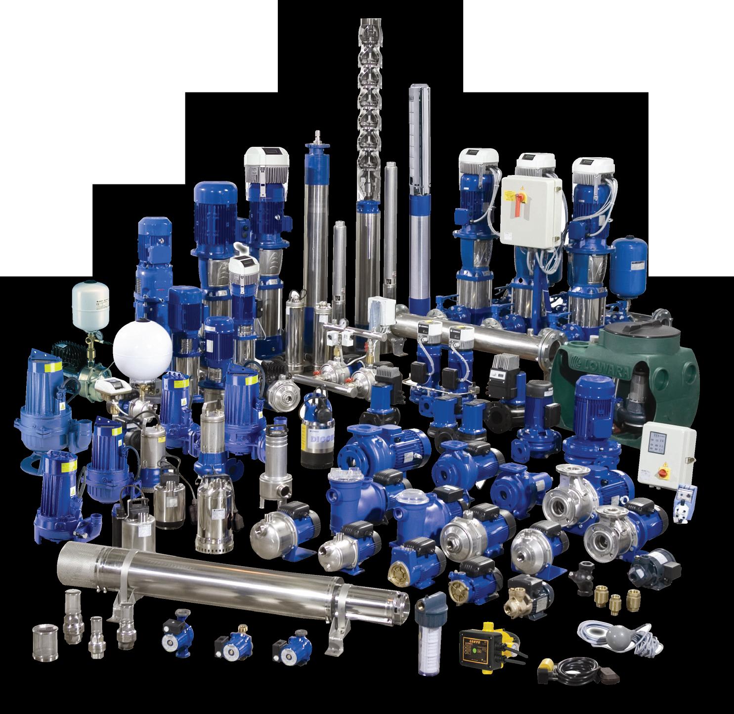
Pump Selection Guide


Commercial Water
Residential &
Lowara
The sealless alternative
Mag-drive pumps offer a sealless alternative to mechanical seal pumps. Instead of a coupling between the driving motor and the pump shafts to power the impeller, the drive shaft is surrounded by magnets, allowing the magnetic field to be transferred to the impeller shaft through a completely enclosed shell through which the fluid passes.
Sealless pumps have the benefit of zero leakage as well as reduced wearing and maintenance issues. As a result, sealless pumps are particularly useful for pumping fluids that you particularly don’t want to leak, ie corrosive, toxic and noxious liquids. Acromet, a provider of innovative pumping solutions, are one of the foremost experts in handling this type of fluid.
Acromet has an extensive range of MagDrive pumps that are designed to meet the high demands of corrosive, toxic and noxious liquids that are widely encountered throughout all industries from Agriculture to Zinc Mining and everything in between.
This issue we take a closer look at the C MAG-PL Series.
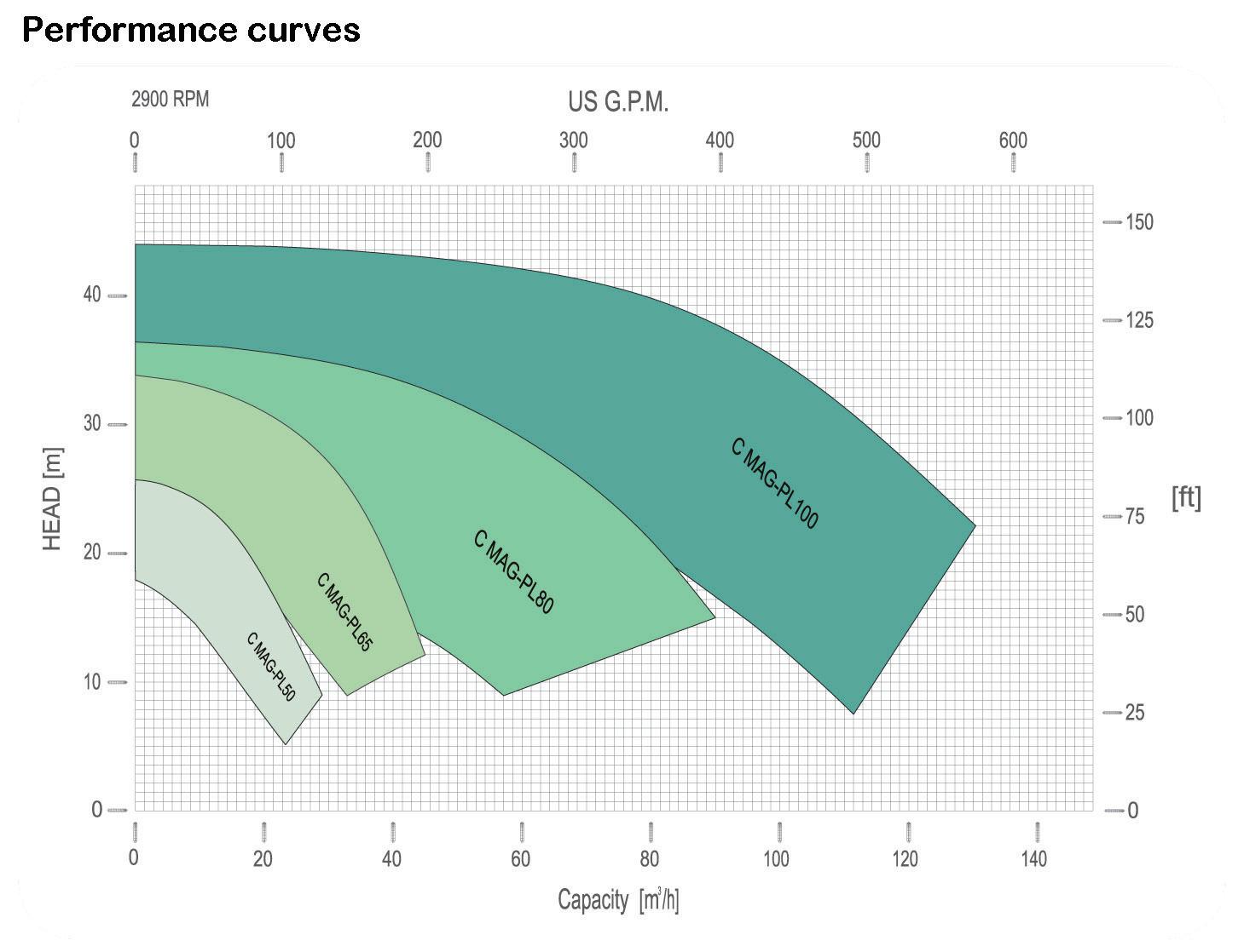
This pump demonstrates how the separation of liquid chamber/atmosphere by means of an isolation shell is the best solution to pump aggressive chemical, high purity liquids and liquids difficult to seal.
The hermetic sealless design is the best solution for the chemical and pharmaceutical industry.
The pump is constructed with closecoupled motors drivers, which are conventional motors drivers mounted directly to pumps frame. No base, coupling or guards are required for this mounting style. It uses universal flanges connections that meet DIN PN16 and the ANSI 150#.
Operating Limits
• Flow up: to 140mc/h
• Head up: to 44m
• Max system pressure: 16 bar
• Max viscosity: 200 cSt
• Temperature ratings:
• from 85°C
• to 120°C
• Electric motors: from 1,5 to 18,5 kW
• ATEX II - / 3G cbk II C T5

PIA MEMBER NEWS
For more information visit www.acromet.com.au
16
Major vacuum pump export to Saudi Arabia
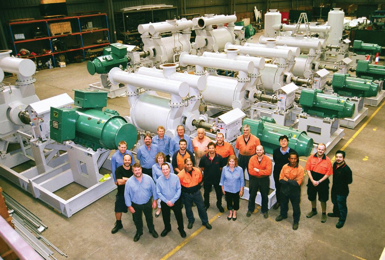
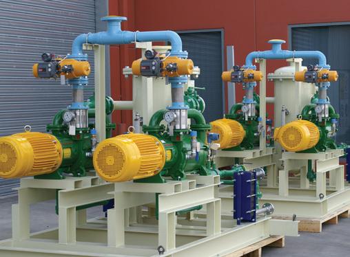
Emtivac Engineering has recently completed a large project with eight liquid ring vacuum pump units for a new Alumina Refinery in Saudi Arabia.
There are 3 x 500 kW units for Pan Filters and 5 x 280 kW units for Disc Filters. The heavy duty liquid ring vacuum pumps are Emtivac N2BE/HE units with Ductile Iron End Castings. The N2BE/HE vacuum pumps were selected due to their unique high efficiency design and low operating speeds at the duty points requested. Gearboxes are water cooled Siemens/ Flender units with sunshades and electric motors from WEG. The entire skid is designed to withstand the harsh environmental conditions in the Saudi desert and the caustic process conditions.
All engineering design & fabrication of baseframes, piping and vessels was carried out by Emtivac and other local Dandenong businesses. Base frames were heat treated and machined after fabrication.
The project specifications and QA requirements were very stringent and a specific project manager was allocated for the duration of the project to ensure all the customer’s requirements were met.

The fully assembled skid for the Pan Filter vacuum pump has a total weight of 24,000 kg, special heavy duty shipping crates were manufactured to safely transport the skids to Saudi and to protect the units on site prior to installation.
This project is the largest completed by Emtivac in its 15 year history but the company has just been awarded an even larger project for 2 x liquid ring compressor packages for Flare Gas Recovery at an oil refinery in Malaysia.

17
PIA MEMBER NEWS
Pump Systems Ltd: solids pumping & mixing specialists
Established in 1984, Pump Systems Ltd is one of Australia and New Zealand’s leading suppliers of sewage pumps and process mixing systems for anaerobic digesters and sludge tanks in the combined municipal and industrial wastewater sectors.
As the Authorised Distributor of Vaughan® Chopper Pumps and Rotamix® Process Mixing Systems for over 20 years, Pump Systems has been involved with the design and delivery of numerous large-scale projects throughout Australia, New Zealand and Singapore, for applications where generic “non-clog” impeller pumps and traditional digester mixing systems struggle to perform or cope with suspended solids in sludge and wastewater.
Designed and developed by Vaughan Company, Inc. in Montesano, USA, the Vaughan Chopper Pump was the world’s first true heavy-duty chopper pump and should not to be confused with other types or brands of chopper pumps, cutter pumps, grinder pumps or macerators. Leading the chopper pump market for more than 50 years, product reliability and positive customer feedback has enabled Vaughan Co. to guarantee the performance and clog-free operation of every unit sold, instilling confidence in the end user through a unique assurance of quality design and dependability. Over the years, the Vaughan Chopper Pump has not only proven its value in problem solving, but has also established itself as the reliable alternative to conventional pumping.
Vaughan Co. is already the producer of the world’s largest chopper pump, but later this year will be releasing a new, even larger 16” discharge model. This revolutionary new chopper pump will be capable of flows up to 3,180 m3/ hr (880 L/s) and will be available in multiple configurations including dry well and submersible designs. The extremely heavy-duty 16W will be ideal for high flow solids pumping applications in large local authority pump stations, influent wet wells, wet weather stations and CSO basins among many others. Vaughan Co. is continuously developing its product range with new configurations, larger sizes, and advances in design and efficiency.
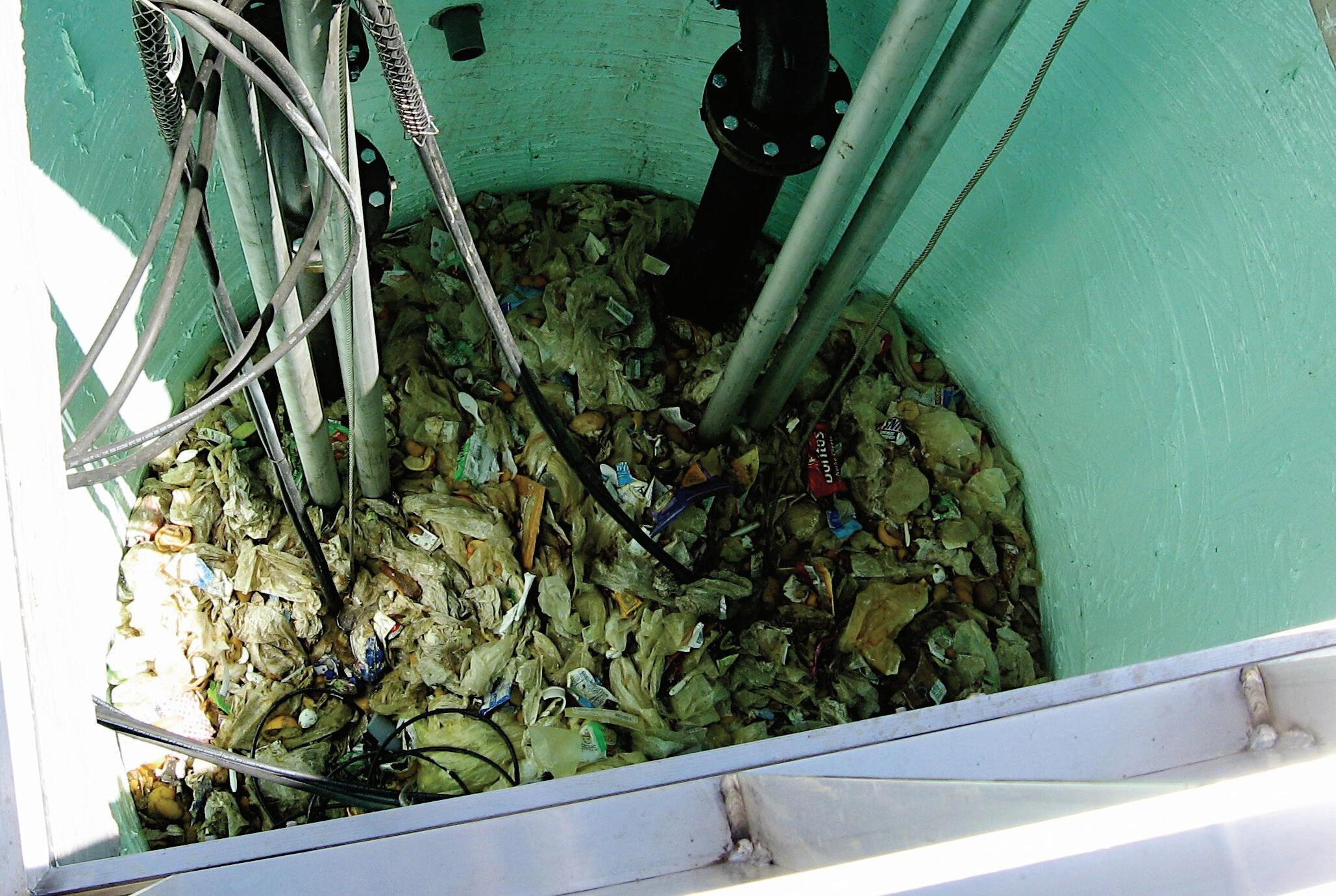
With a proven track record and wealth of industry experience, Pump Systems has supplied hundreds of Vaughan Chopper Pumps for some of the most challenging pumping applications in the region. Local authority and industrial wastewater treatment plants in particular can present major challenges for modern pumping and mixing equipment, an area that is second nature to Pump Systems. Dealing with suspended solids such as rag, plastics, grit and fibrous material is often an ongoing battle for most plant operators due to continuous binding and clogging of pumps, valves and heat exchangers. The Vaughan Chopper Pump eliminates these problems by effectively chopping all solids in suspension as they enter the pump. The conditioned slurry is then easily pumped away without the risk of clogging.
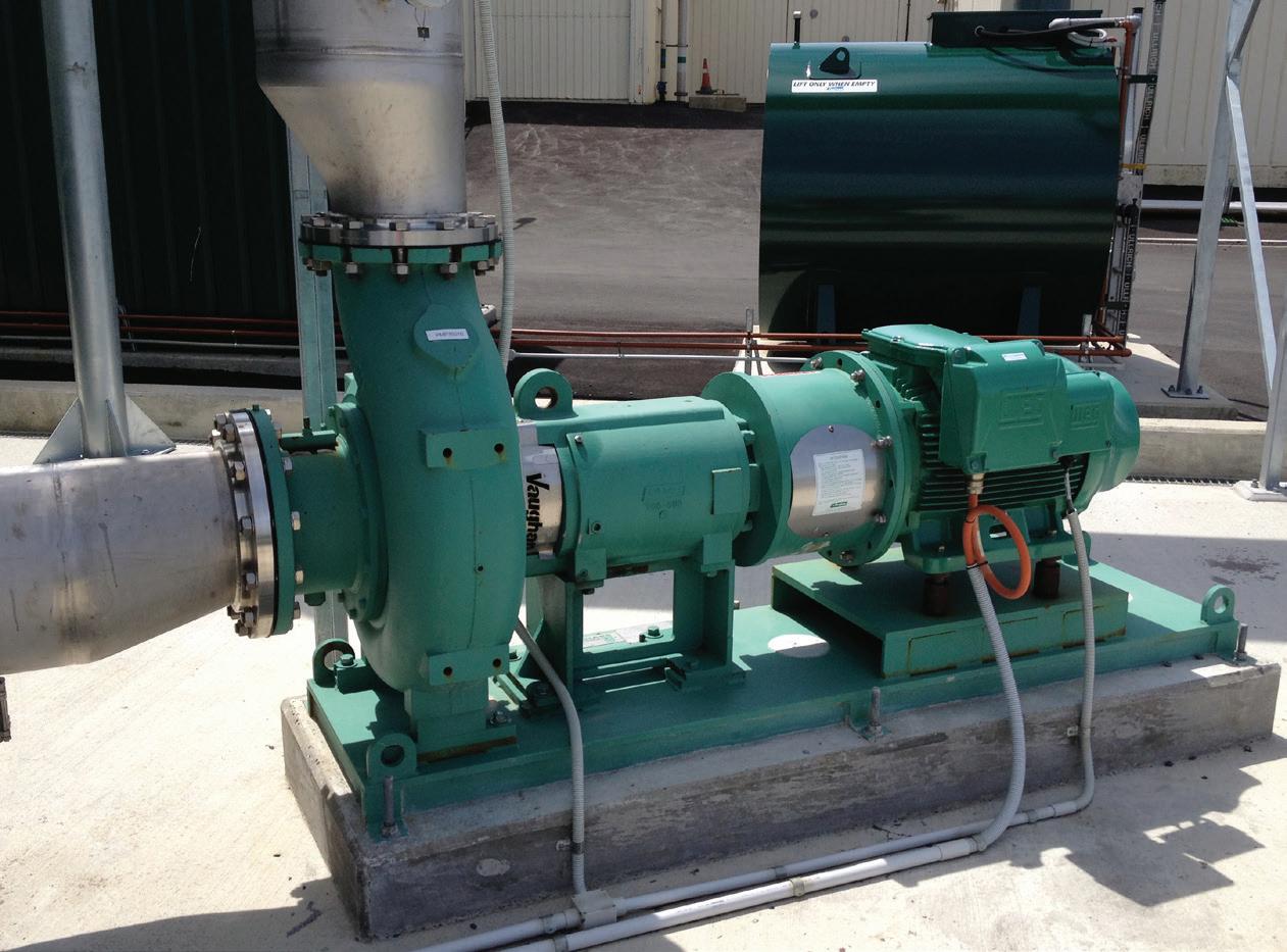
The heavy-duty design of the Vaughan Chopper Pump means that
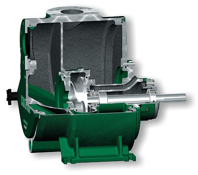
it is ideal for critical and severe-duty applications, including the pumping of screenings and septage containing raw, concentrated solids. All main components are heat treated to a minimum of Rockwell 60C hardness for impact and abrasion resistance, while externally adjustable cutter clearances allow operators to effectively “delay” the wear process, maximising pump service life. Vaughan Chopper Pumps are ideal for applications where roping and clogging can cause problems for other equipment and processes, such as clarifier scum pits, clarifier underflow to thickeners, transfer and preconditioning of return and waste activated sludge, thickened and digested sludge, as well as dealing with F.O.G. (Fats, Oils and Greases), where organic wastes are processed to enhance methane production in anaerobic digesters. The Vaughan Chopper Pump also plays a pivotal role in the Rotamix System, the world’s most cost effective means of mechanical hydraulic mixing for anaerobic digesters, sludge storage tanks, and other high volume applications.
Pump Systems has Vaughan Chopper Pumps and Rotamix Systems operating throughout Australasia, with installations in municipal wastewater treatment plants and large industrial sites located Christchurch, Dunedin, Auckland, Hamilton, Tauranga, Palmerston North, Sydney, Perth, Queensland, Adelaide, Tasmania and Singapore to name a few. The Vaughan Chopper Pump not only plays a key role in the municipal sector, but has also proven its value across a range of difficult industrial applications including meat, vegetable, seafood and poultry processing, pulp and paper mills, mining, chemical and automotive industries, as well as biogas.
To learn more about Pump Systems Ltd and for further information on Vaughan Chopper Pumps and the Rotamix System, please visit www.chopperpumps.com.au.
18
PIA NEW MEMBER PROFILE


✓ Multiple
configurations
available
including
horizontal
end
suction,
vertical
wet
well,
recirculating,
submersible
and
self-‐priming
✓ Heat
treated
components
for
impact
and
abrasion
resistance
and
externally
adjustable
cutter
clearances
for
extended
pump
life
✓ Flows
up
to
3,180
cubic
metres
per
hour
and
heads
up
to
70
metres
✓ More
than
50
years
of
solids
handling
experience
✓ NON-‐CLOG
PERFORMANCE
GUARANTEE
ON
ALL
PUMPS


Is
your
so-‐called
‘solids
handling’
pump
struggling
to
cope
with
debris
in
your
waste
stream?
A
blocked
pump
in
a
critical
process
can
be
frustrating,
especially
when
it
results
in
expensive
downtime
and
repairs.
VAUGHAN®
Chopper
Pumps
are
designed
and
built
to
eliminate
clogging
problems
by
chopping
and
conditioning
all
suspended
solids
as
they
enter
the
pump.
Sludge
and
sewage
containing
rag,
grit,
plastics
and
fibrous
material,
as
well
as
difficult
industrial
and
food
process
wastes
are
handled
with
ease.
Stop
wasting
time
and
money
unblocking
your
standard
‘non-‐clog’
and
in
the
world’s
leading
chopper
pump.
For
more
info,
19
visit
www.chopperpumps.com.au For
guaranteed non-‐clog
performance, invest
in
a
VAUGHAN®
Chopper
Pump... Pump
Systems
Ltd
-‐
VAUGHAN® Authorised
Factory
Representative
Australia
&
New
Zealand Free
Phone:
1800
121
452
|
sales@chopperpumps.com.au
|
www.chopperpumps.com.au Sick
and
tired
of
pump clogging
problems? THE
VAUGHAN
pump
invest
ADVANTAGE
Fighting black oil and understanding bearing housing upgrade opportunities
By Heinz P. Bloch, P.E. ; Westminster, Colorado, USA
Because rolling element bearings are standard components in most centrifugal pumps, scores of authors have devoted much time and effort to bearing performance issues. Lubricant degradation is among the many topics, although not many articles have dealt extensively with the root causes of oil ring-related contamination and formation of “black oil.” The term “black oil” refers to seemingly random lubricant discoloration that can be experienced over a rather short period of time. Needless to say, any manner of repeated short-term degradation of the lube oil affects bearing reliability. Equipment outages result and time and money will inevitably be spent. That’s why the subject of “black oil” should be important to us. Black oil is the result of one of only two possible events. One of these is rooted in an overheating of the lubricant; the other blackening event is often caused by slivers of black elastomeric material abraded from O-rings. The risk of experiencing considerable wear with dynamic (or moving) O-rings in certain bearing housing protector seals will be pointed out.
Bearing
housings with or without oil rings?
An estimated 45% of oil-lubricated industrial pump bearing housings are furnished with inexpensive oil rings that lift the lubricant from an oil sump (Figure 1). In some applications, oil rings are used to keep the oil volume more uniformly mixed, i.e., to prevent oil stratification. The term stratification describes a layer of hot oil floating near the top of the oil sump.
We might assume that perhaps another 45% of oil-lubricated pumps are designed for operation without oil rings. In the typical “without oil-ring” design, the oil level should reach the centre of the lowermost ball, roller or other bearing element. This oil level centering requirement would be difficult to achieve if, as shown in Figure 1, the bearings supporting the shaft had different diameters. We estimate that, in the remaining 10% of oil-lubricated pump bearings, the
lubricant is probably applied by pumparound (“pressurized”) means, or the housings incorporate flinger discs (Figure 2), or oil mist is being used.
To confirm, no oil rings are needed at slow-to-moderate shaft peripheral velocities. Shaft peripheral velocities
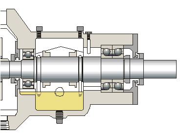
Figure 1: Process pump bearing housing with static oil sump and two oil rings
are a function of operating speed (rpm) and shaft diameter, inches or mm. It is found convenient to express peripheral velocity as “DN-values”-- the product of inches of shaft diameter multiplied by shaft rpm. For example, a 70 mm (~2.75 inch) bearing operating with a shaft turning at 1,800 rpm would have a

Figure 2: Bearing housing with thrower (or “flinger”) disc. Accommodating this stainless steel lube thrower disc requires that the thrust bearings be placed in a cartridge. The outside diameter of the cartridge is slightly larger that the diameter of the flinger disc. Note bearing housing seals at shaft protrusions
(Source: AESSEAL plc, Rotherham UK, and Rockford, TN)
RELIABILITY 20
DN-value of 4,960; values below 6,000 are somewhat arbitrarily considered low-to-moderate DN numbers.
In DN < 6,000 designs, both housing geometry and constant level lubricator settings are generally selected to allow lubricating oil to reach the center of the lowermost bearing ball or rolling element. However, if the DN value exceeds 6,000 it will be risky to keep the oil level at the center of the lowermost bearing ball. Potentially excessive friction-induced temperatures would likely result. These temperature concerns led to the decision to lower the oil levels in many of the larger API-compliant pumps operating at 3,000 and 3,600 rpm. In these, oil levels are customarily set well below the periphery of even the lowermost bearing ball. Because oil then no longer reaches a portion of the lowermost part of the bearing, some other means are needed to feed, lift, spray, or splash the lubricant into the pump bearings. Oil rings are often the least expensive component used for lifting oil into the bearings. But oil rings have limitations, and some of these are either little known or not well publicized. Oil ring malfunctions may deprive bearings of oil or simply allow oil to overheat. As mentioned in our introduction, that’s one possible source of black oil. But how and why can oil rings malfunction? What application limits exist?
DN-value limitations and attempts to improve on troublesome oil ring lubrication
Oil rings may be unstable for a number of reasons; oil ring instability (“wobbling”) is not a new phenomenon. To ensure proper operation, Ref. 1 cites surface velocity limits around 3,500 to 4,000
fpm (~18-20 m/s) with water cooling. The stipulated water cooling serves to maintain a constant oil viscosity; oil, of course, will become thinner when heated. Without water cooling of the lubricant, Ref. 1 advises users to stay well inside the stable limit for oil rings and not to exceed peripheral velocities of 2,000 to 2,500 fpm (~10-13 m/s).
Another source, a major multi-national oil corporation’s “Lube Marketing Course Book,” suggests a DN value of 6,000 as the threshold of instability for oil rings. As a precautionary rule, both of these authoritative texts warn that oil rings in field situations tend to become unstable whenever DN, the product of shaft diameter (inches) and speed (rpm), enters the region from 6,000 to perhaps 8,000. With its DN value of 7,200, a 2-inch shaft at 3,600 rpm would thus operate in the risky or instability-prone zone, whereas equipment with a 3-inch shaft operating at 1,800 rpm (DN = 5,400) might use oil rings without undue risk of instability. In just one more example, a 3-inch (~76 mm) diameter shaft at 3,600 rpm would operate with a peripheral velocity of 2,827 fpm (~14.4 m/s).
One might not wish to quarrel with pump manufacturers pointing to satisfactory experience with higher peripheral velocities. However, field situations are usually far from ideal. In real-life situations, shaft horizontality and oil viscosity, depth of oil ring immersion, bore finish and out-of-roundness are rarely perfect. The vendor’s test stand experience is of academic value and field experience trumps all else. Reliability professionals must define safe operating ranges and use a good measure of conservatism.

Figure 3: A new oil ring (left) and a badly worn oil ring (right). Oil rings tend to abrade; the abraded particles cause bearing distress (Photo courtesy of TRICO Corporation, Pewaukee, Wisconsin)
Over the years, conservatism was probably sought by a number of pump manufacturers. In the 1990s one major pump manufacturer decided to look into the matter of oil ring instability and black oil formation. The manufacturer’s report was later presented as “Investigations into the Contamination of Lubricating Oil in Rolling Element Pump Bearing Assemblies” at a widely respected Industry Conference in 2000 (Ref. 2). The scope of both the report and the lecture presentation was to relate an analysis of factors affecting the short-term contamination of liquid lubricants in ring-oil lubricated rolling element bearings. “Short-term” was defined as intervals ranging from one hour to several weeks. The analysis dealt with the pump manufacturer’s standard range of centrifugal pumps, and short-term oil degradation had been reported in a number of installations (Ref. 3).

21
RELIABILITY
The presenter described the tests conducted and discussed their results. He then made a number of recommendations (reported here under “presenter”) to which this writer would like to add relevant editorial comments in brackets (as “author’s comment”).
• Unless slightly preloaded, backto-back mounted angular contact thrust bearings allow the unloaded side to skid. The unloaded bearing then gets quite hot (Ref. 3). [Author’s comment: The pump manufacturer had supplied back-to-back angular contact bearings and had inserted a thin shim between adjacent bearing inner rings. Competent users have, since the late 1960’s, insisted on using matched pairs of lightly preloaded or flush-ground backto-back angular contact bearings. Shims are shunned. Moreover, there are applications where the user would be best served by lightly preloaded angular contact bearings with, say, a 15-degree contact angle on one, and a 40-degree contact angle on the mating bearing. This would prevent skidding of one of the bearings.]
• Much of the contamination originated from metal particles being worn off the bronze oil rings (Figure 3) which were erratically hitting the adjacent components (Presenter’s observation). [Author’s comment: Abrasive wear has been known to occur with unstable oil rings. Factors contributing to instability are discussed below.]
• Instead of metallic oil rings, plastic oil rings should be used (per presenter). [Author’s comment: Highperformance polymers are indeed less likely to suffer from abrasive wear than metallic oil rings. However, simply switching to non-metallic rings treats the symptoms; it does not address the cause of the problem.]
• Instead of using mineral oils that were either too light (ISO Grade 32) or too heavy

Figure 4: A “dynamic” (moving) O-ring in close proximity of grooves will abrade if it contacts any of the sharp groove edges shown in this sketch
(ISO Grades 68 and higher), ISO Grade 46 lubricants should be used (per presenter).
[Author’s comment: With ISO Grades 32 and lower, the resulting oil film is often too thin to prevent metal-to-metal contact in rolling element bearings for centrifugal pumps. SKF commented on the matter in Ref. 4]
The various recommendations found in Ref. 2 and the author’s comments deserve to be further examined in terms of root cause problem identification.
Examining the causes of darkened oil
We know from experience that closely observing both new and “used” oil rings will prove very revealing. Abrasive wear of oil rings is easily recognized; a previously chamfered edge is now razor-sharp or burred (Figure 3), or an originally strawcolored lubricant has recently turned dark. Many copper-containing alloys leave a grayish color; pure overheating generally produces free carbon and causes the oil to become black. A good reliability verification technique would include measuring the “as installed” oil ring width and to later compare it with its “as-found” width. Measuring will avoid the cost of analyzing for contaminant composition. Needless to say, abraded oil ring material is suspended in the oil and bearing life is cut short by the abrasion product.
Years of operating and troubleshooting experience confirm that some pump manufacturers’ “old practice” of using low viscosity “thin” ISO Grade 32 oil is flawed. While acceptable for sleeve-type (also called “plain”) bearings, ISO Grade 32 oil is risky for the rolling element bearings found in the average process pump. In many small or mid-size pumps with rolling element bearings, thin oil exacerbates the problem of premature bearing failures.
The presentation based on Ref. 2
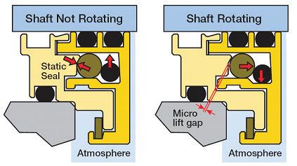
Figure 5: Because there are no sharp edges to contact, the two “dynamic” (moving”) O-rings (see arrows) in this bearing housing protector seal will have extremely long life (Source: AESSEAL plc, Rotherham UK, and Rockford, TN)
recommended ISO Grade 46 lubricants. However, we need to look at industry experience overall; we also might examine the position taken by competent bearing manufacturers in the matter (Ref. 4). While oil viscosity is an important parameter, tweaking the oil viscosity selection and substituting ISO Grade 46 (mineral oil) for the previously used ISO Grade 32 will not make much difference. Relatively minor changes in ambient temperatures negate the effect of small viscosity changes; numerous temperature vs. viscosity charts are available to confirm the validity of this concern. Moreover, a renowned bearing manufacturer had determined decades ago that film thickness and film strength limitations rendered ISO Grade 32 mineral oils undesirable for rolling element bearings in many centrifugal pumps (Ref. 4).
Years earlier, this bearing manufacturer had asked users to restrict mineral oil ISO Grade 46 lubricants to bearings operating at temperatures not exceeding 70°C (158°F) and recommended ISO Grade 68 (again assuming mineral oil) for bearing operating temperatures not exceeding 80°C (176°F). However, to simply use more viscous, thicker oils would tend to slow down an oil ring and is not usually recommended.
While black oil can form because oil rings slip, skid, or bounce, black oil can also be found randomly in slower speed bearings that are not using oil rings. In those instances black oil formation is likely the result of the oil level receding by a fraction of an inch, essentially low enough to just barely reach the “bore rim.” We use the term “bore rim” to describe the edge (at the 6 o’clock position) of the bearing’s outer ring bore.
Bearing housing
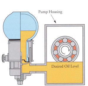
Figure 6: Traditional constant level lubricators sometimes allow the pressure inside the bearing housing to rise above ambient. In that instance, the oil level will be pushed below the Desired Oil Level and oil may no longer reach the bearing’s rolling elements (Source: Trico Manufacturing Corporation, Pewaukee, Wisconsin)
22 RELIABILITY

And here is another concern: Lube oil supplied into a bearing must be allowed to return to the main oil sump. This is accomplished by the small passageway near the 6 o’clock position of the left bearing in Figure 1. Note, however, that this passageway is missing from the same position on the right bearing. This omission is important because it deprives the oil to the right of the thrust bearing set from returning to the sump and freely mixing with the main oil volume. (Note that the same return passage is inexplicably missing from both sides of Figure 2).
Black oil will also form if bearing housing protector seals incorporate “dynamic” O-rings. Notice that the design in Figure 4 has a dynamic (moving) O-ring located between its rotating and stationary components. The O-ring will be damaged if it contacts either of the two sharpedged grooves. The same failure mode does not exist in a design where an O-ring makes only very brief contact with the relatively large and well-contoured surface of a more advanced bearing housing protector seal design (Figure 5).
Oil level and oil application concerns must be addressed
There have been many instances where the transparent reservoir bulbs of constant level lubricators showed adequate levels of oil which, understandably, led operators and maintenance technicians to assume the oil level in the bearing housing was also at the correct height. Hydraulic laws should convince us that such an assumption is not always correct. The lube oil level in a bearing housing cannot coincide with the level in the base of the constant level lubricator if the internal bearing housing pressure is different from atmospheric pressure. It should be noted that, in a typical non-balanced constant level lubricator the actual oil level in the die-cast base of the assembly (Figure 6) is contacted by ambient air. Ambient air, in most industrial locations, carries water vapor and airborne contaminants, either of which will reduce bearing life. Also, according to
the laws of physics, slightly elevated pressures in the bearing housing will lower the oil level in this housing. The displaced oil volume will be pushed into the die-cast base and the occasional overflow will be seen on the equipment base.
Using a properly pressure-balanced constant level lubricator assembly (Figure 7) goes a long way towards curing the problem. A suitably sized balance line back to the bearing housing ensures this pressure equalization. Together with advanced models of bearing housing protector seals --magnetically closed or rotating labyrinth styles -- a pressurebalanced constant level lubricator makes a fully enclosed oil-lubricated bearing environment feasible. (An advanced rotating labyrinth bearing protector seal
will be almost as good as a dual-face magnetic seal, and we leave it to the reader to determine what constitutes advanced rotating labyrinth seals, Refs. 5 and 6). Compared to non-balanced constant level models, the typical incremental cost of an average-size pressurebalanced constant level lubricator is $40. Just think if you retrofitted 200 pumps with advanced bearing protector seals and pressure-balanced lubricators. Calculate the value of avoiding even a single unscheduled pump downtime event in each of the next five years. And imagine the peace of mind those relatively minor incremental monetary outlays would buy. That would be a tangible and verifiable reliability improvement step for your pumps.
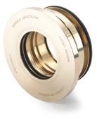
LabTecta®66 Bearing Protectors ‘Eliminate
over 50% of bearing failures’
• Identification mark — Aids correct fitment
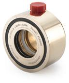
• Shut off valve — Prevents chamber breathing
• Twin rotary ‘O’ ring drive — No shaft wear. Retrofittable on shafts previously worn by lip seals
• Repairable — Face shield design allows fast, and most importantly, safe repair of the LabTecta®66. No chemicals or special tools required
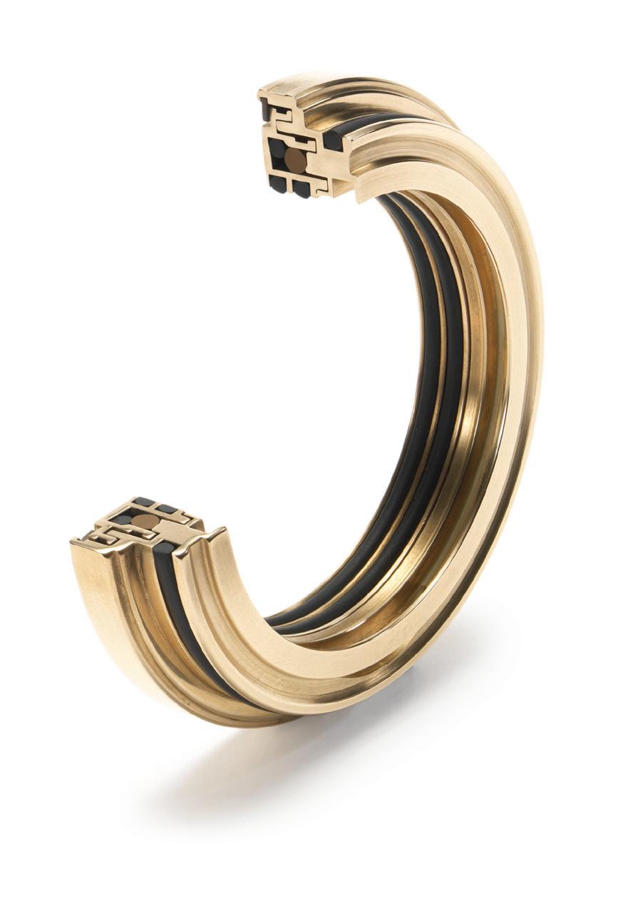
• Positive location — Press fit design & ‘O’ ring seal
• Oil retention — Velocity reducing cavity combined with a unique zenith barrier design creating twice the chance of preventing oil egress
• A true non-contacting labyrinth design with a shut-off design that really works
• Proven to increase equipment reliability in pumps, electric motors, fans, pillow blocks, steam turbines and gearboxes
• IP66 certified designs that conform to IEEE Std. 841-2001

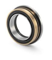


RELIABILITY
Figure 7: A pressure-balanced constant level lubricator (Source: Trico Manufacturing Corporation, Pewaukee, Wisconsin)
Visit www.LabTecta.com for a 3-minute video showing statistics and technology
The LabTecta®66 shut-off valve has an axial energizing member. As equipment rotates, centrifugal force causes a temporary micro-gap to be created, allowing the expansion of the oil / gas mixture in the bearing housing. When equipment stops, the centrifugal force ceases and the micro-gap is closed, forming a perfect seal. This stops atmosphere from being sucked back into the bearing-housing, preventing the damage caused by breathing. Shaft Rotating Housing Housing Shaft Not Rotating Shaft Rotating Housing Housing Shaft Not Rotating Essential Micro-Gap When Rotating Effective Vapour-Seal When Not Rotating • Oil expulsion port — Returns oil to sump AESSEAL AUSTRALIA Pty Ltd, Head Office: 12 Counihan Road, Seventeen Mile Rocks, QLD 4073 Ph: +61(7) 3279 1144, Fax: +61(7) 3279 1067 E-mail customer.service@aesseal.net.au LabTecta®66ST LabTecta®66FS LabTecta®66AX 66 www.labtecta.com Get high performing application-specific designs, quickly — Special designs are available to upgrade steam turbines (LabTecta®66ST), axial movement (LabTecta®66AX), oil flooded applications (LabTecta®66FS), split-seal designs for easier installation (LabTecta®66RDS), pillow blocks (LabTecta®66PB), top / side entry (LabTecta®66TE / SE) and inboard / outboard air purge for difficult environments (LabTecta®66IAP / OAP).
RELIABILITY
From an operating and maintenance perspective, don’t overlook that there must always be a partial vacuum in the upper part of the lubricator bulb. If caulking is used to cement the transparent bulb to a metal body in either Figure 6 or Figure 7, it must be realized that this caulking has a finite life. Once it develops tiny aging cracks, rainwater may enter via capillary action. Finally, traditional constant lubricator assemblies are direction-sensitive and should be mounted on the correct side of the bearing housing. The manufacturer’s instruction manuals describe this requirement, as does Ref. 5. The rotation arrow in Figure 6 is important. Constant level lubricators must be mounted on the “up-arrow” side of the bearing housing.
More on the limitations of oil rings
Assume the rolling element bearing housings are routinely furnished with oil rings and the manufacturer is either unable or unwilling to offer superior lube application methods in pumps or other equipment with high shaft (or bearing bore) DN-values. In those instances, the polymer oil rings recommended in Ref. 2 will be a (minor) step in the right direction. Still, it should be kept in mind that all oil rings have limitations which include the following:
(a) a DN limitation, i.e. certain rpmtimes-oil ring-bore values should not be exceeded;
(b) oil rings are viscosity-sensitive, and Ref. 2 merely confirms that oil rings slow down in thicker fluids
(c) oil rings are immersion-sensitive, and disputing it would be denying the effects of viscous drag. This drag is (approximately) proportional to the velocity
(d) oil rings must not be out-of-round or “slightly oval.” Reliability-focused users should not allow more than 0.002” (0.05 mm) ring eccentricity (Refs. 1 and 5). Oil rings bought from the lowest bidder may not have been stress-relief annealed. They will not remain sufficiently round in service
(e) oil rings will run down-hill; they tend to malfunction if the total shaft assembly is not truly horizontal. They will malfunction if allowed to touch the inside of a bearing housing
Industry now has access to and benefits from superb laser-type shaft alignment tools. However, to achieve good alignment the installer typically shims up one end of the pump, thereby jeopardizing shaft horizontality. Also, the user will experience occasions where, in spite of
lubricant delivery via “constant level” lubricators, the oil level is actually lower than the set point indicated on the constant level lubricator assembly. Recall from our earlier comments that understanding how these lubricators function is very important and can save the user much pain.
Needed: a better choice than oil rings and constant level lubricators
Most 3,000 and 3,600 rpm pumps obtain splash lubrication through the action of oil rings. Yet, oil rings have inherent shortcomings that often make them a poor choice for risk-averse plants, Flinger discs (Figure 2) securely mounted on the shaft seem to offer a better choice than oil rings. Many reputable European pump manufacturers avoid oil rings and use flinger discs instead; some have done so for many decades. Because flinger discs are secured to the shaft, they are not subject to the influence of shaft horizontality, oil viscosity, depth of immersion, shaft surface finish and ring concentricity. These five factors inevitably vary from pump to pump; they result in an infinite combination of variables. Some of these combinations tend to make oil rings prone to malfunction. These malfunctions occur more often than deemed desirable by best-of-class user companies.
Visualize also that oil rings operate at slippage conditions relative to the shaft surface and that abrasive wear often results from this slippage. Slivers or particles of oil ring material have ruined thousands of bearings. Fortunately and unlike oil or slinger rings, flinger discs (Figure 2) are securely fastened to the shaft and avoid slippage and abrasion problems. However, when metal flinger discs are made with diameters larger than the bearing housing bore, a bearing mounting cartridge (Ref. 3, 3rd Edition, pp. 162) may be required to allow assembly without interference. Mounting cartridges are machined to precision tolerances and this adds to pump cost.
In the 1990s flexible discs were developed to get around the need for this added-cost cartridge. They “fold up” while being inserted through a smaller diameter bearing housing bore and snap open after passing through this housing bore (Ref. 5). Needless to say, it is important that the designer-manufacturer selects the proper elastomer and opts for a disc geometry that gives long and trouble-free service life at predetermined permissible – safe -- peripheral speeds. Suitable elastomers are costlier than originally thought, which explains why
“wobbling”
we see few plastic flinger discs in pump bearing housings.
Recommendations and future improvements
Some day, an enterprising inventor or pump manufacturer may turn his back on cost-cutting and will return to ingenuity. He or an enterprising company may then develop a better alternative to oil rings or even flinger discs for rolling-element bearing housings. This alternative may be a smart device just short of the wellproven oil mist, and less costly than the widely known conventional, pressurized, oil pump-around systems. Reconfiguring part of the shaft to serve as the rotor of a progressive cavity pump, or utilizing the principle of magnetically driving a small internal lube pump may be feasible. Direct-driving a housing-internal impeller is clearly feasible for picking up some oil, pressurizing a small stream of this oil, and then spraying it into the bearing rolling elements.
As time progresses and if we are really fortunate, motivated engineers serving on the various API Standards Committees might address the various oil application issues and carefully listen to all sides of the story. Meanwhile, owner-purchasers of process centrifugal pumps should consider paying close attention to well-documented user experience and depend not only on the routine answers offered by some pump manufacturers. Let your equipment manufacturers know that your plant is dealing with real-world issues and that you are interested in lasting failure avoidance measures for chronic maintenance problems. Try to discourage temporary patch-ups and the flawed solutions that don’t cure root causes. Consider rejecting action steps that require maintenance expertise bordering on perfection. Don’t get into the habit of rewarding the lowest bidders by purchasing only from them. If you don’t heed this advice, the long-term experience will almost certainly prove disappointing.
It is important not to miss the bottom line of this article. If the safety and reliability of a plant were dependent on
24
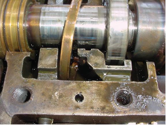
Figure 8: Oil ring with evidence of damage due to
upgrading bearing lubrication of vulnerable pumps, trust neither wobble-prone oil rings (Figure 8) nor lubed-to-centerof-lowermost ball applications. Be a bit more reluctant to put faith in most, if not all, constant level lubricators for really trouble-free lubrication (and trouble-free takes into account human imperfection of operator and mechanics). So, in most cases, try to get away from 18th century oil rings, which would also eliminate questions on oil ring material selection preferences. If at all possible, favor dry-sump oil mist for lubrication and for preservation of standby equipment, whenever this modern oil application method is cost-justified.
If oil mist cannot be justified, the author would -- without the slightest hesitation -simply take oil from the drain location at the bottom of the bearing housing (Ref. 5). This oil would be piped to the suction of a small (yet highly reliable) fractional horsepower canned motor pump and generate a few psi of pressure. About two or three gpm (8 to 12 liters) of pressurized, filtered ISO Grade 68 PAO/Diesterbased synthetic oil from the bearing housing drain would be forced through two spray nozzles into the inboard and outboard bearings of the most vulnerable process pumps. Implementation of such a strategy would close the book on issues involving black oil. Spraying oil into the bearings would terminate endless arguments over the merits of maintaining oil viscosity at tight limits, the adequacy of metallic versus plastic oil rings, the maintenance requirements of constant level lubricators, and the ramifications of hot bearings.
References:
1. Wilcock, Donald F., and E.R. Booser, (1957) “Bearing Design and Application,” McGrawHill Book Company, New York, NY 10121
2. Bradshaw, Simon; “Investigations into the Contamination of Lubricating Oil in Rolling Element Pump Bearing Assemblies”, Proceedings of the Texas A&M Pump Users Symposium (2000).
3. Bloch, Heinz P.; “Improving Machinery Reliability,” (1982 and later Editions), Gulf Publishing Company, Houston, TX, ISBN 0-87201-376-6; ISBN 0-87201-455-X; ISBN 0-88415-661-3
4. SKF USA Inc, “Bearings in Centrifugal Pumps, Application Handbook” Publication 100-955 (1995), pp. 20
5. Bloch, Heinz P. and Allan Budris; “Pump User’s Handbook—Life Extension,” (2006) 2nd Edition, The Fairmont Press, Lilburn, GA 30047, ISBN 0-88173-517-5
6. Bloch, Heinz P.; “Pump Wisdom: Problem Solving for Operators and Specialists,” (2011), John Wiley & Sons, Hoboken, New Jersey, ISBN 978-1-118-04123-9
About the author
• 4” 0.5kw to 7.5kw
• 6” 7.5kw to 45kw
• 8” 30kw to 93kw
• 10” 75kw to 150kw
• 12” 93kw to 300kw
• 14” to 30 “ up to 2500kw
Heinz P. Bloch resides in Westminster, Colorado. He holds B.S. and M.S. degrees in Mechanical Engineering and is an ASME Life Fellow. His professional career spans five decades and includes long-term assignments as Exxon Chemical’s Regional Machinery Specialist for the United States. He has authored well over 520 publications, among them 18 comprehensive books on practical machinery management, failure analysis, failure avoidance, compressors, steam turbines, pumps, oil mist lubrication and practical lubrication for industry. His “Pump Wisdom” (2011) explains issues and reasons why process pumps world-wide suffer from many elusive repeat failures.
Sterling Submersible Motors.
Engineered and proven in the toughest conditions

2 pole, 4 pole, 6 pole and 8 pole 415v, 1000v, 3300v, 6600v and 11000v.
All motors are wet stator re-windable.
Materials of construction include: Cast Iron, 304ss, 316ss, Duplex 2205, Super Duplex 2507, CuNi 90 10, NiAl Bronze, Zeron 100.
Sterling Pumps is an ISO9001 certified company.

25 RELIABILITY Manufactured in Melbourne service facility in Melbourne & Perth 14 Sharnet Circuit Pakenham Victoria 3810 Australia P +61 3 9729 5044 F +61 3 9729 3522 E info@sterlingpumps.com.au WWW.STERLINGPUMPS.COM.AU
Oil mist lubrication
By Don Ehlert,
Oil mist is an ideal method of lubrication for rotating equipment in geographic regions that are windy, hot, humid, cold, damp, and dusty or anywhere that air borne particulates and moisture contamination may be present. Improving equipment reliability translates into a safer and more reliable plant with more production of product. Oil mist lubrication impedes the ingress of air borne contaminates, delivers clean oil and provides a dramatic impact on equipment MTBR (Mean Time Between Repair). One Australian refinery with approximately 500 pumps uses oil mist with excellent results.
Pure Oil Mist or Dry Sump Lubrication describes the lubrication of rolling element bearings without an oil sump or grease in the bearing housing; the oil mist is the only means of lubrication for the bearings. Oil mist is an aerosol of oil particles that are 1 to 3 μ in size. These small particles are referred to as dry mist; they are too small to lubricate contacting surfaces such as rolling element bearings. The dry mist, 1 to 3 μ sizes, allows the particles to be transported throughout a piping distribution system for lubrication of bearings in rotating equipment with an air flow up to 180 metres away from the oil mist generator, OMG (Oil Mist Generator). Ambient temperature swings have minimal impact on mist density after it leaves the OMG; provided the oil consumption rate is calibrated and proper flow rate is maintained, allowing it to be used in both hot and cold climates. Quality synthetic oils, PAO (Polyalphaole-

RELIABILITY 26
Total Lubrication Management and Marty Williams
Figure 1
Mist inlet
Mist outlet/ vent drain
Mist inlet
fin) or Diester, are recommended for use when ambient temperatures fall below 4° C (40° F). When mineral oils are used they must be paraffin free to prevent plugging of the reclassifier orifices. Reclassifiers are orifice fittings that convert the dry mist to wet mist, particle sizes larger than 15 μ and greater, for lubrication of the bearings rolling elements. Converting the dry mist to wet mist takes place by increasing the velocity of the small particles through the orifice where they coalesce, impinge on each other, and grow in size. These larger particles then wet out on surfaces and provide a clean, continuous supply of fresh oil. Oil particles that do not grow in size are vented away from the equipment housing and are referred to as stray mist. The loss of oil mist to individual or multiple pieces of equipment does not mean an immediate equipment failure. Should the oil mist system fail or header line breaks; it is recommended that normal system operation should be reinstated prior to the end of the current maintenance shift; within four (4) hours. It is not to be set aside for the next maintenance shift. There are only two items that can completely stop the generation of oil mist; the loss of air and/or oil. Electrical power is not required to generate oil mist. Clean, dry instrument air is required for the generation of oil mist; should the instrument air system fail the entire plant/ unit will be shutting down and lubrication will not be an issue. The average oil mist system consumes approximately four litres, (one gallon), of oil in a 24 hour period. For large scale systems the OMG normally has a misting chamber that holds 23 to 34 litres (6 to 9 gallons) of oil with a bulk supply of 284 to 416 litres (75 to 110 gallons) standing by for refilling the misting chamber; the chances of running out of oil are extremely remote.
When applying oil mist to new or rebuilt equipment that may have dry bearings, without any lubricant on them, it is recommended that oil mist lines should be connected immediately after the machine is set in place to allow oil mist to coat the bearings prior to start-up. Equipment coming from a staging or storage area where bearing preservation was not provided is likely to have corrosion or particulate accumulation on the surfaces and bearing failure could be imminent with any method of lubrication.
Benefits of Pure Oil Mist
Pure oil mist is the ultimate oil filter as it breaks oil down to particle sizes of 1 to 3 μ. Larger particles that may bond with solid particulates or water are too heavy for transport throughout the distribution system and fall out of suspension.
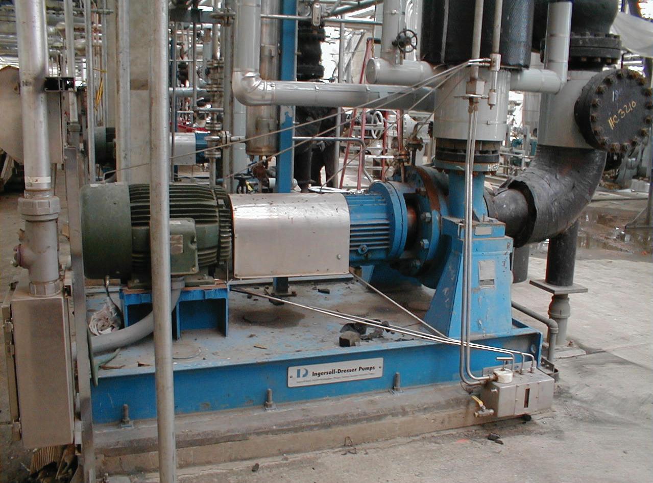

 Figure 2
Figure 4
Figure 3
The results are a continuous film of fresh clean oil being supplied to bearing surfaces in a pressurized/aerosol form. The bearing housings internal pressure is maintained at approximately 0.125 PSI which inhibits thermal cycling and/ or the ingress of external air borne contaminates i.e. dust and moisture. The overall result is bearings without an oil sump operate up to 10° C (30° F) cooler with no recirculation of hot or contaminated oil. Oil mist not only lubricates the operating equipment; it also protects and preserves the standby or idle equipment insuring optimum bearing conditions when service is required. Using pure oil mist means a longer MTBR, mean time between repair, lower life cycle cost, reduced man hours for lubrication tasks, less equipment repairs, less oil inventory on site, less safety incidents due to mechanical seal failures which are initiated by premature bearing failure and less failures that may result in a fire.
Pure Oil Mist on pumps
Current API 610 pump specifications require that pumps shall have NPT (National Pipe Thread) connections outboard of the bearings. This allows oil mist to be applied into a central connection point between the bearings with venting outboard of the bearings or apply oil mist outboard of the bearings and venting out the bottom drain port as shown in figure 1. Either way insures that oil mist will pass through the bearings from side to side before exiting the bearing housing. The arrangement shown is the preferred method of lubrication as it allows the reclassifier to be sized for the individual bearings which is superior to having a single reclassifier serving both the thrust and radial bearings. When retrofitting oil mist to existing or older pumps the illustration shown is recommended when pumps are operating at 3000 RPM or higher and Kw is150 (200 HP) or greater. A single oil mist application point located in the middle point of the bearing housing is acceptable when operating less than 3000 RPM and Kw is less than 150 Kw (200HP) when lip or labyrinth seals are used. When bearing isolators are used two mist application points are mandatory. Oil mist lubricates pumps in operation and it protects and preserves the internal bearing surfaces from corrosion or false bernelling when sitting idle. Oil mist protects equipment 24/7 in all climates and conditions. Experience from many facilities has proven that pure oil mist is beneficial to rotating equipment reliability. User experience indicates that equipment having sat idle in excess of twelve months have been
started without incident. There were no changes in vibration readings from when the machines had previously been in operation.
Pure Oil Mist pillow block bearings
Pillow block bearings are commonly lubricated with grease or an oil sump and these types of bearings are commonly used on FD (Forced Draft) or ID (Induced Draft) fans, figure 3. Grease becomes contaminated over time due to the natural process of bearing operation. Grease, like oil, requires changing at regular intervals and in un-spared equipment this may not be an option. The contaminated lubricant then becomes a rubbing compound that severely shortens the life of the bearings rolling elements. Idle bearings are subject to lubricant contamination from thermal cycling, condensation, wash down water and other forces that apply pressure, even a small amount, to the bearing housing seals. Keeping contaminates out is virtually impossible when oil sump is the norm; however the slight pressure created by the oil mist assists in keeping the bearing housing free of debris and moisture. Applying pure oil mist on pillow block bearings is very effective and inexpensive when the oil mist system
About the Authors
Don Ehlert is currently Manager for EPC Sales at Total Lubrication Management Co., a Colfax Fluid Handling Company, located in Houston, TX. His current responsibilities include providing technical training and sales presentations. Don is also responsible for quotation assemblies for both domestic and foreign engineering companies and end users. He provides technical support to oil mist user’s world wide.
Since joining TLM in 1984, he has filled positions in equipment assembly, field maintenance, field installation, field management, sales and sales management. He has been instrumental with the development of oil mist related products and accessories for special applications.

is already in place for the surrounding equipment such as the pumps and motors.
When a large scale system is not in the immediate area a small modular unit may be used with excellent results. Modular units may be so basic that only a clean instrument air supply is required for operation, figure 4. These units are ideal for isolated equipment such as tank farm pumps or fan bearings where a larger system is not justified. A notable benefit of the oil mist system is the elimination of oil containers sitting around the machines which promotes cross contamination of lubricants and contamination from outside sources.
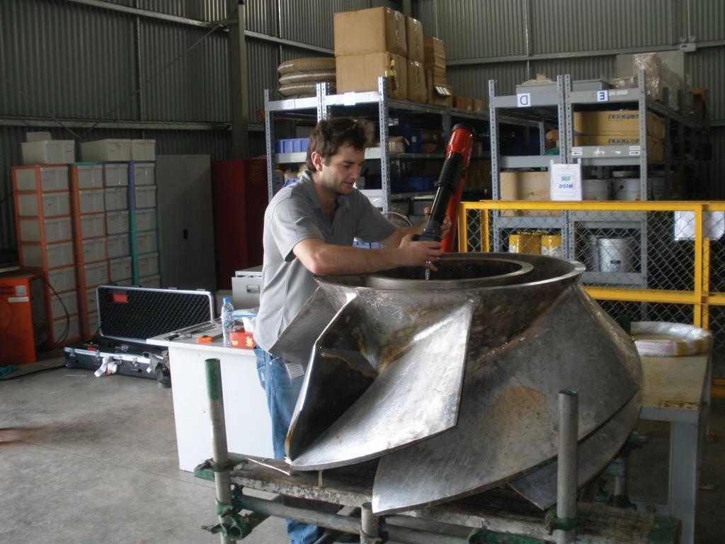
As a final point, any machine with rolling element bearings has the potential to be successfully lubricated with oil mist lubrication. Refinery experience demonstrated that bearing life is extended well past normal expectations; in many cases exceeding 130,000 hours in service with no degradation of the bearing structure. Special applications require a good understanding of oil mist and should not be attempted before seeking advice from qualified personnel. When properly applied oil mist will move equipment reliability to a much higher level.
Marty Williams started life as a Maintenance Technician in the mid-seventies at a major oil refinery in the UK, progressed through the ranks leaving in 1989 as a Maintenance Supervisor to emigrate to Australia.
He started at a major oil & gas facility in Western Australia in 1990 as a Maintenance Supervisor until 2000 when he was seconded to SRC in Singapore for nine months as a Reliability Engineer. On his return to Australia he became part of the Reliability Group working on all aspects of refinery machinery reliability. He introduced oil mist lubrication to the refinery in 2000 being the SPA for the project and has installed a total of thirteen oil mist systems covering the majority of rotating equipment and is now Machinery Engineer at the facility.

28
RELIABILITY


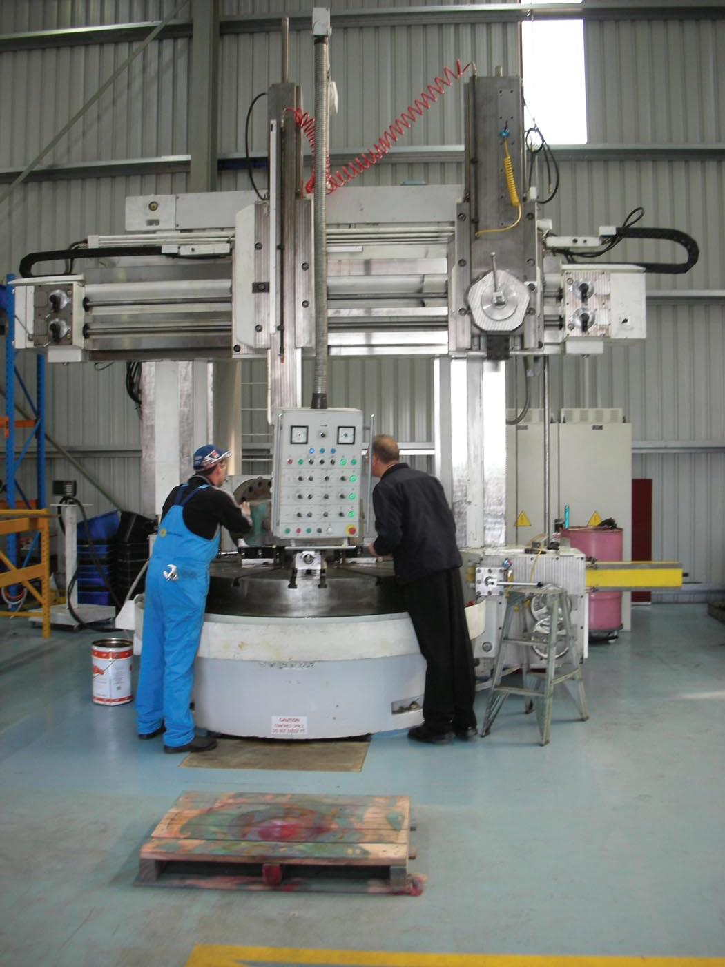
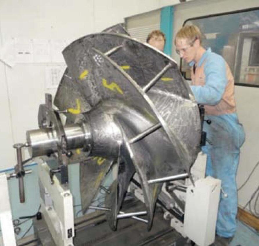
Comprehensive Pump Support
Reliable & Responsive Service
Engineered Pump Rebuilding
Since 1969, Hydro has built its worldwide pump service organization by bringing a high level of engineering expertise and quality service to the pump aftermarket. Hydro Australia works with our customers to evaluate and understand the root causes of pump degradation or failure and to provide unbiased engineering analysis, quality workmanship and responsive field service for improved plant operation.
Certified Service Centre
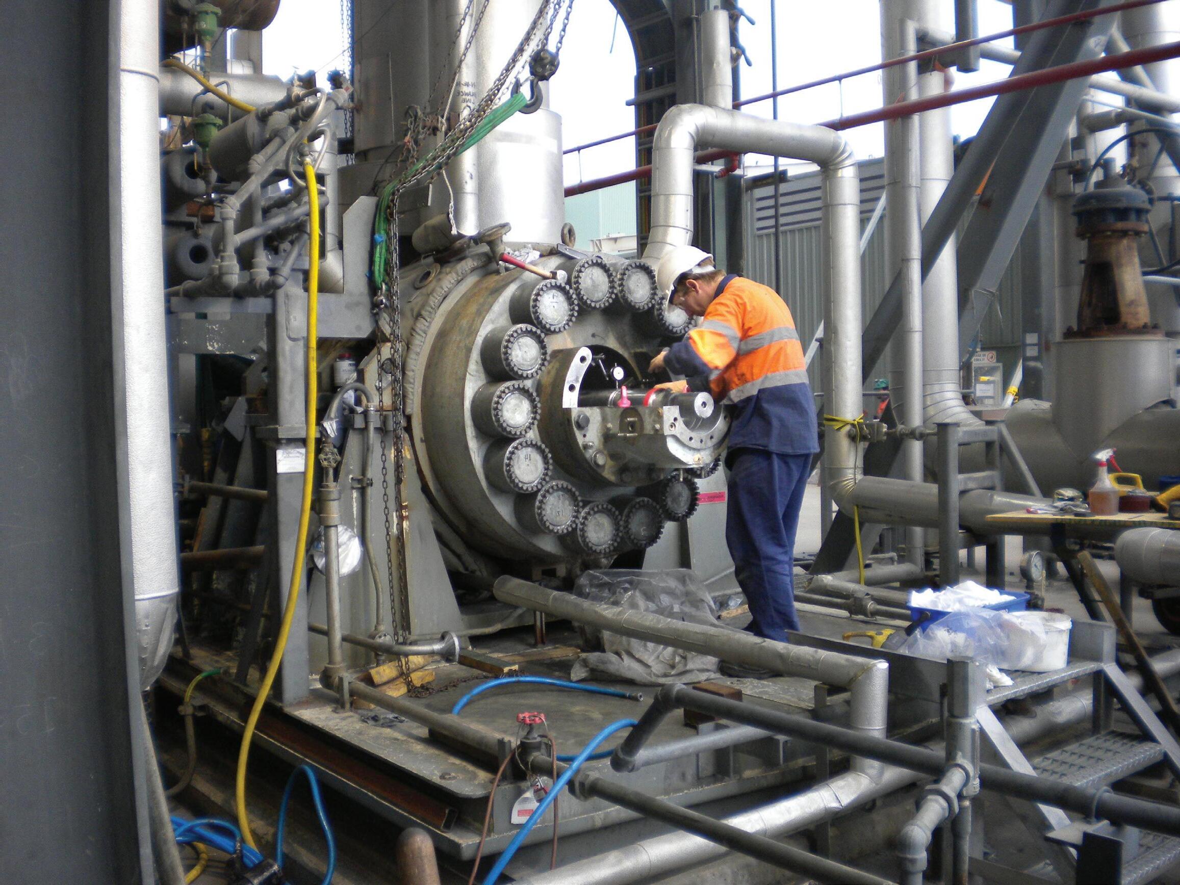
Hydro Australia has always been committed to Quality and Occupational Health & Safety. Hydro Australia holds the AS:NZS ISO 9001:2008 certificate in addition to the AS:NZS 4801 and AHSAS 18001 certificates.
Turnkey, Field Service and 24/7 Emergency Response
Hydro Australia’s Field Service team has extensive knowledge of pumps from most major manufacturers and provides turnkey service, installation / start-up supervision, field machining, vibration analysis, laser alignment, pump system troubleshooting and emergency field response 24 hours a day, 7 days a week.
Pump Parts
When you require a part and are facing a long lead time, Hydro Australia can meet your needs in a reduced time frame through our reverse engineering, patternless casting and integrated manufacturing processes. Hydro's engineers review and evaluate all parts to offer important upgrades and apply new technologies that will reduce wear and improve reliability.
Pump Testing - Managing Risk
Ensure your pump will perform as required. Hydro’s 5000HP Performance Test Lab, located in the United States, is compliant to API610 and Hydraulic Institute standards and can test horizontal, vertical, and submersible pumps.
Training
Hydro teaches practical solutions and troubleshooting techniques for common pump problems and offers specialized hands-on training programs. View upcoming courses online at www.hydroinc.com.
Call Hydro Australia at (03) 51650 390 with your pump service inquiries or contact Ross Bertolimobile: (0418) 581190 email: ross@hydroaustralia.com.au.
A Hydro Company Hydro Australia, Pty. Ltd. Hydro Australia Pump Service Centre Morwell, Victoria 3840 www.hydroaustralia.com.au (03) 51650 390
Thermodynamic performance testing and monitoring
By Malcolm Robertson, Managing Director, Robertson Technology Pty Ltd, Joondalup, WA- www.pumpmonitor.com
Many organisations are attempting to improve the energy efficiency and reliability of their pump systems, and to verify and maintain the energy (and carbon) savings. This requires accurate measurements, in particular before and after any improvements.
The thermodynamic method often provides the most accurate on-site measurement of pump performance, for both individual pumps and the overall pump system. In many cases the uncertainties in pump efficiency and flow rate are less than 1 and 1.5 % respectively.
Temperature and pressure probes are required before and after the pump, to measure the differential temperature and pressure. The efficiency is determined from this information plus the thermodynamic coefficients for the fluid (for water, these coefficients are readily available from international standards such as ISO 5198 – Precision class tests). The flow rate is then derived from the efficiency, head, and power to the pump.
The performance of an instrument employing the thermodynamic method is largely determined by the design, accuracy and long-term stability of the temperature probes, since it is often required to measure the differential temperature across the pump to an accuracy of 0.001°C (1 mK).
Long-term tests have shown that the calibration of Robertson Technology temperature probes is typically stable within an experimental error of <0.2 mK over a five-year period. Each probe contains two temperature sensors. Software detects any discrepancies between the two sensors, giving a warning if one of the sensors starts to drift. The probes are thus suitable for permanent installations for continuous monitoring.
Techniques used are
• Individual pump testing with a portable unit (Robertson P22P Pump Monitor)
• Simultaneous multi-pump measurements with a portable unit
• Continuous monitoring with fixed units (Robertson P22F Pump Monitor) on every pump in a pump system
Theory
For a rotating device such as a pump, blower, or turbine, there are four main performance variables. These are efficiency, flow, power, and head, and they are linked by ‘The Pump Equation’. Knowing any three, the fourth can be found.
For an electrically driven pump: ηp.ME.PW = q.ρ.g.H
The left-hand side is the electrical power (watts, or joules per second) applied to the fluid, after losses in the motor drive and pump: -
ηp is the pump efficiency (expressed as a fraction)
ME is the motor and drive efficiency (expressed as a fraction)
PW is the electrical power to the motor (in watts)
The right-hand side is the energy per second imparted to the fluid, and also has the units of watts (joules per second): -
q is flow rate, in m3/s
ρ is the fluid density, in kg/ m3, and is a function of temperature and pressure g is the acceleration due to gravity, in m/s2 H is pump total head, in m
The terms ρ, g, H, PW and ME are common to all pump test methods, with ρ and g being obtainable from reference tables, and ME supplied by the motor manufacturer.
With the thermodynamic method, pump efficiency ηp and total head H are measured by temperature and pressure probes, and motor input power PW is measured by a power meter. Thus the flow rate q can be found thermodynamically without a separate flow meter, and with low uncertainty, since it is relatively easy to check the calibration of the temperature and pressure probes, and the power meters:
q = ηp.ME.PW / ρ.g.H
Thermodynamic vs conventional On-site constraints often make it difficult to accurately measure pump efficiency under installed conditions by the same method that pump manufacturers traditionally use for works tests. In the conventional technique, pump efficiency is calculated from the Pump Equation as follows:
ηp = q.ρ.g.H/ ME.PW
This requires measurement of flow rate, head, and power. The accuracy of the pump efficiency measurement is determined by the errors in the measurement of q, H, PW, and Me
In practice, the flow rate, q, is the most difficult to determine accurately. Many pumps do not have accurate, individual flow meters, which are high cost items, especially for larger diameter pipes, and

30
RELIABILITY
Figure 1. Portable probes
can be difficult or impossible to install, maintain, and carry out calibration checks on-site. Flow meter accuracy can be dependent on installed straight, clear pipe lengths prior to and after the measuring device, the pump’s operating point and other factors, such as build-up of debris in pipes or on sensors. Often, just the total flow from the station, or from each group of pumps, is measured. Pipe installations may be compromised in the interest of minimising civil costs.
Conventional flow meters, either installed or strap-on, are likely to have an accuracy of 5 to 10%, and this will lead to corresponding errors in the pump efficiency measurement. These errors are so large that the conventional method is impracticable for accurate measurements of energy savings, or for pump refurbishment or system control decisions.
Additionally, pumps operating in parallel need individual flow meters for continuous monitoring to be meaningful.
The thermodynamic method has the following advantages:
• Pump efficiency and flow rate are accurately measured
• The flow rate measurement is independent of velocity profile
• Measurement is accurate even when pumps are cavitating, or when there is air entrainment (this is because the thermodynamic method measures mass flow rate, and converts to volumetric flow rate using the fluid density. In contrast, many types of conventional flow meter will also respond to water vapour or air bubbles)
• Calibration depends primarily on temperature, pressure, and power

Robertson Technology Pty Ltd
Western Australia
Tel: 08 9300 0844
mail@pumpmonitor.com
www.pumpmonitor.com
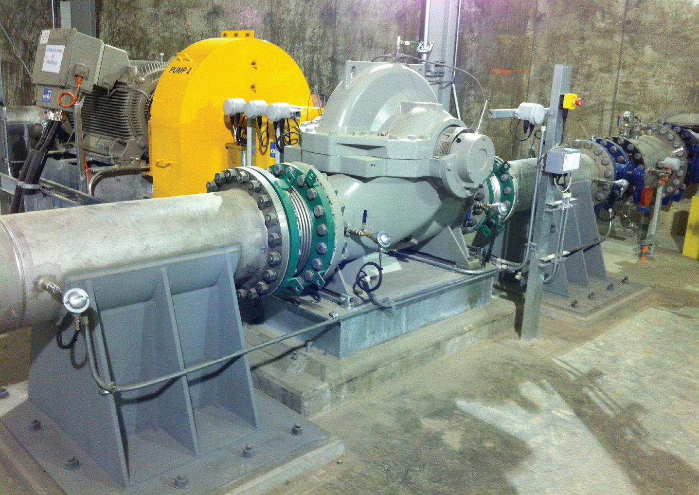
measurements, and can be checked
• Each pump has its own flow meter, so pump systems can be optimised for efficiency and flow rate. This is particularly important for energy savings when pumps are operating in parallel.
Measurement of temperature and pressure
With portable units for snap-shot measurements, immersion temperature probes are generally used, protruding 50 mm into the fluid flow. These require tapping points before and after the pump, in pipe work.
Figure 1 shows immersion temperature probe passing into fluid via a T-piece and gate valve. A pressure probe is also attached to the T-piece. A constraint
is that the unsupported length of the temperature probe should be within certain limits, depending on the water velocity, to avoid vibration and excessive stress due to vortex shedding.
For continuous monitoring, and for high temperature and pressure applications, the temperature probes are inserted via thermowells, and are fitted separate to the pressure probes (see Figure 2). This minimises vibration and long-term stress, as the unsupported length of the temperature probes can be quite short.
Two other methods of measuring differential temperature, water sampling, and surface temperature sensors, have been developed for applications where it is not possible to fit standard tapping points. However, there are some constraints on their use.

31
Joondalup,
RELIABILITY
Figure 2. High power pump fitted with fixed unit for continuous monitoring.
Discharge Pressure probe
Suction Temperature probe
Suction Pressure probe
Discharge Temperature probe
on-site
RELIABILITY
Applications
Robertson Technology has been developing the thermodynamic method since 2001, with the assistance of several federal and state grants, and we have clients in 14 countries, including major pump manufacturers. Over 90% of world pumps are in the Northern hemisphere, so we travel.
Here are the main applications that we have been involved with, and the corresponding countries. Over 95% of our business is with water utilities and power stations.
Water and wastewater utility pumps (Australia, New Zealand, UK, USA, Canada, Singapore, Malaysia, Greece, Spain, Philippines, India, South Korea, Hong Kong): Pump motor power varied from a few kW to 5 MW. We are often testing multiple pumps in parallel. Cavitation is seen quite regularly. We have installed a number of fixed systems for continuous monitoring of pumps in parallel, and pump system optimisation and scheduling (Australia, USA, India, and Hong Kong).
Coal and gas power stations (Australia, New Zealand, UK, Hong Kong): Boiler feed pumps up to 8 MW (requiring higher temperature and pressure ranges), condensate extraction, cooling water, fire pumps.
Nuclear power stations (USA): Circulation pumps. The water velocity was quite high and we used a water sampling method. Soon we will be testing other types of pump.
Air blowers (Australia): These required development of slightly different range probes. We’ve also compared immersion and surface temperature measurements.
Desalination plants (Australia, Spain): We are able to test pumps in all stages of the process.
Irrigation pumps (Malaysia): Low head vertical pumps in wet wells. Cavitation often seen.
Offshore rig (Malaysia waters): Sea water lift, heating medium, cooling medium, and fire pumps. We used surface temperature sensors as there was no way of inserting tapping points.
Marine (UK): Surface and subsurface vessels. We compared immersion and surface probes.
Hydro-turbines (Romania): Turbines are generally measured according to IEC 60041 standard.
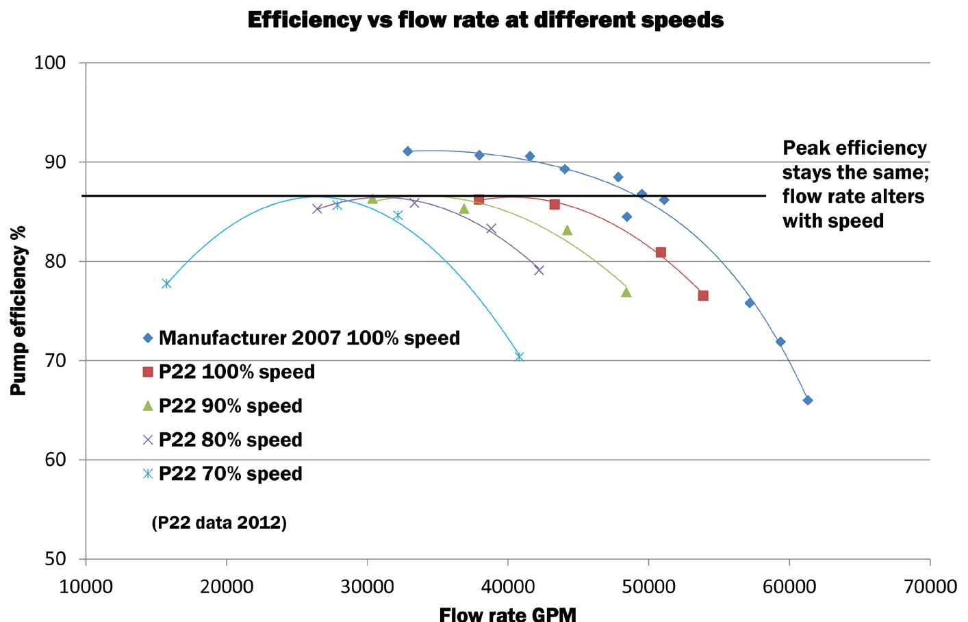
The higher the total head, the higher the differential temperature signal, and the more accurate the measurement. Similarly, the lower the pump efficiency, the higher the differential signal, and the more accurate the measurement. So the worse your pump is, the better we can measure it!
As a rule of thumb, the uncertainty in pump efficiency measurement will be less than 1% for total head above 20 m. The uncertainty in the flow rate will always be a bit higher, as it will include the uncertainty in the pump input power measurement.
Techniques have been adapted to test vertical pumps in wet-wells. These take longer to test, as much more data has to be collected, and filtered for stable suction temperatures.
Speed control
We are able to interface tachometers with the P22, and obtain speed in real time, also correcting data dynamically on the basis of the affinity laws.
In a parallel pump system, all pumps must be well-matched, otherwise the weaker pumps will be forced towards shut-off. If VSDs are installed, they should be fitted to all pumps, and speeds adjusted for optimum performance. A pump fitted with a VSD cannot costeffectively be used as a ‘top-up’ pump with fixed speed pumps in parallel.
Figure 3 demonstrates that efficiency is largely unaffected by speed changes, as would be expected from the affinity laws. Manufacturer’s data for this 5 MW pump was taken in 2007. Five years later we measured pump performance over a range of speeds. The peak efficiency has degraded but does not vary with speed; flow rate alters with speed.
Future developments
Continuous monitoring will naturally identify the most opportunities for energy savings, as the full range of operational conditions is thereby covered. Rapid deterioration in pump performance, changes in system curve, cavitation, and control system limitations could occur at any time. We expect many more installations, with interface to SCADA, and emphasis on pump system optimisation for energy and carbon savings.
The repeatability of pump efficiency measurements is typically 0.2%, so early detection of potential problems is possible with continuous monitoring.
The thermodynamic method can be extended to hydrocarbons, but the equipment required is more complex and requires hazardous area certification.
About the Author
Malcolm Robertson grew up in Zambia, then originally trained as a physicist, obtaining a PhD in thermoluminescence dosimetry from the University of Surrey, UK. The development of instrumentation for ionising radiation, nuclear medicine, and XRF mineral analysis gave him experience in temperature measurement, analogue electronics, and mechanical design which has now been applied to the thermodynamic method for energy efficiency and flow rate measurements.
He relocated from the UK to Perth in 1990, for lifestyle reasons. Robertson Technology has supplied instrumentation and test services internationally for pump, blower, and turbine performance measurements, since 2002.
32
Figure 3. Efficiency vs flow rate at different speeds
Is your pump reliability in the balance?
Pump reliability is a critical factor for commercial and industrial facilities to reduce their maintenance costs and unscheduled downtime, while increasing the equipment return on investment.
Before we can look at pump reliability first we must ask what the pumps expected life is. What life should you be expecting from your current pump? Remember this may not be the pump life you have historically, or are currently achieving, as your current reliability may indeed be poor.
Pump reliability is an issue that involves several elements including maximising the life of the pump components and avoiding any premature failure. You don’t want to run the pump to failure as this never happens at a convenient time, catastrophic failure is to be avoided at all cost.
You also want to be reasonably wearing out the pump service components, including seals and bearings, to maximise their return on investment. Replacing seals and bearings is a costly exercise, and so the optimum life target is where the components have almost worn out and returned maximum working life, while not being at risk of total failure. Finding this optimum position is where you should be targeting your pump reliability, and is where Industrial Dynamic Balancing can help.
Industrial balancing is the procedure
where the mass distribution of a product, be it a pump, roller, impeller or the like, is accurately measured and suitably adjusted. Imbalance of rotating components is one of the most common sources of machine faults in rotating assemblies, pumps and fans, and is a significant issue in terms of pump reliability.
Bearings, seals, housings and foundations can be subjected to very high stresses and greater wear caused by vibration resulting from unbalance. Industrial balancing and vibration analysis on rotating machinery enables the early detection of faults before breakdown, and also assists extend the life of pump motor bearings and seals. With seals and bearings accounting for up to 90% of premature pump failures dynamic Industrial Balancing can improve your pump reliability, and lengthen service life. Simply put products with unbalanced parts often have a shorter service life.
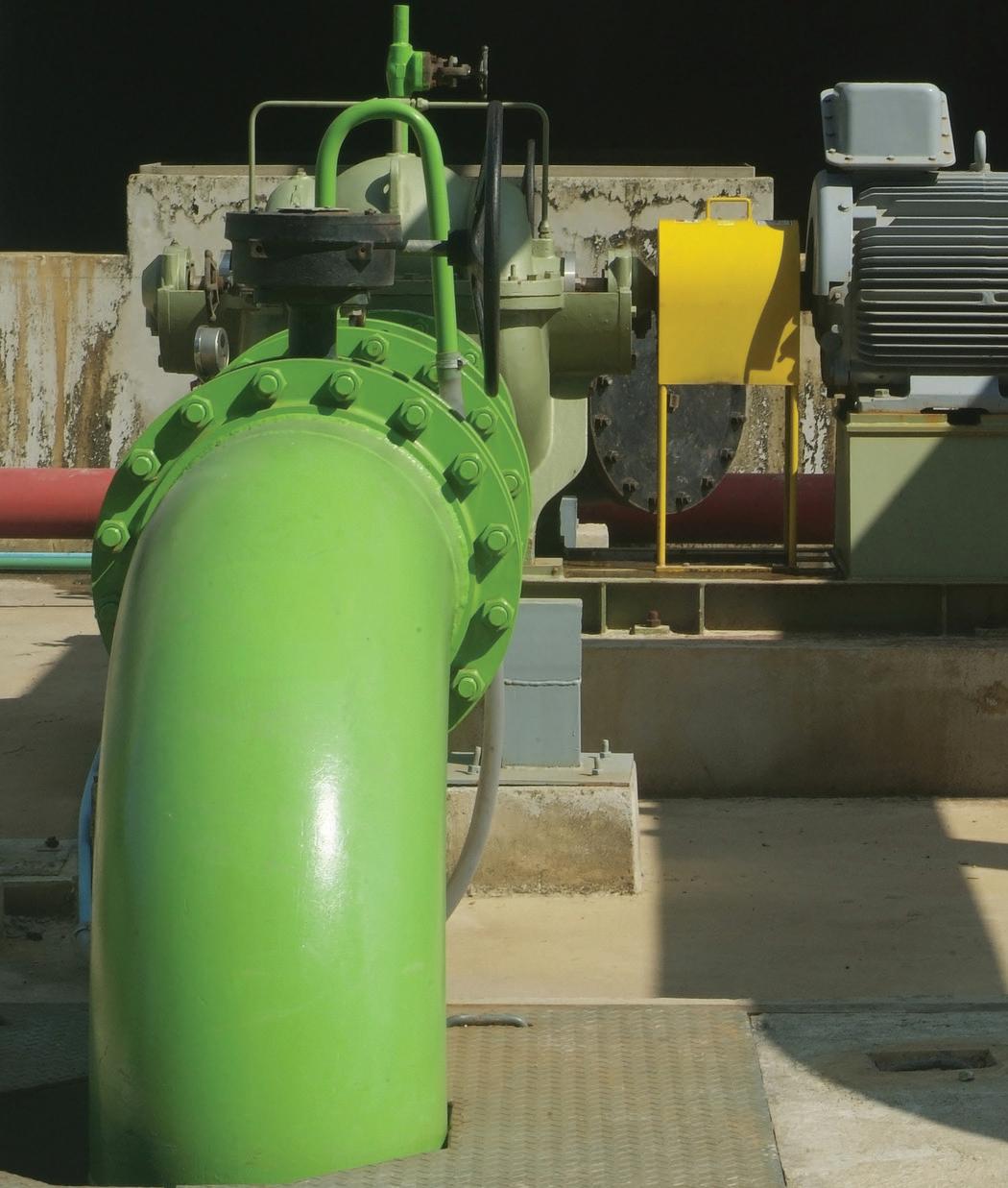
requirements. Owned and operated by qualified mechanical engineers, members of the Australian Institution of Engineers, with years of experience in mechanical engineering and industrial balancing. Precision Balancing has been offering a range of specialised balancing services for pump impellers since the company began, and has worked on a huge range of models and sizes. Precision Balancing offer personalised service including on site balancing, and quick turnaround or emergency after hours breakdown services.
Precision Balancing has been offering in house and on site dynamic balancing and vibration analysis services since 1989 and have the equipment, skills and experience to satisfy your industrial balancing

For more information on how industrial balancing can help you in achieving machine harmony visit www.precisionbalancing.com.au.
33
Imbalance is a common source of faults in rotating assemblies, pumps and fans. Balance Matters! Precision Balancing can help! (03) 9758 7189 precisionbalancing.com.au RELIABILITY
Inside Sydney Water
In this ongoing interview series, we talk in-depth with the end users of pumps across a range of industries and applications. This edition we interview Bruce Maunder, Sydney Water Senior Specialist in Pumping Systems, to get an inside view of Sydney Water.
Procurement process
Tell us about your process
During the last thirty or more years Sydney Water has been gradually devolving itself of what has been seen as non-core activities. As a consequence, the direct procurement of pumping equipment has increasingly been rolled up into large design and construct contracts or alliances and not procured by Sydney Water directly. These contractors are generally required to meet Sydney Water established technical specifications with review by Sydney Water of equipment at various hold points.
We have had long term submersible pump contracts in place for at least 20 years as these cover the majority of the pumps used. Developers and our maintenance contractors can now procure these new and replacement pumps under new contracts.
Where conventional pumps are required they can be purchased as either bare
shaft for replacement applications or a complete pump unit with driver and baseplate on a one off basis.
Do you supply a duty point or a system curve to vendors?
For applications where there is a single known duty point, then this is usually only supplied, however, for more complex and variable operating conditions the complete range of system curves and conditions are supplied. All designers are encouraged to obtain pump vendors approval on the application and installation design.
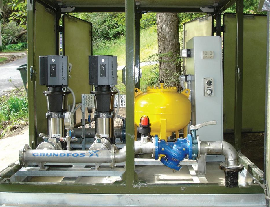
Who is responsible for drawing up the equipment specification?
Sydney Water has its own Civil, Mechanical and Electrical standard technical
specifications, however it is the responsibility of the project design engineer to ensure that the equipment supplied is fit for purpose and meets life expectancy and reliability KPIs. Technical data sheets with our requirement and provision for the suppliers offer is included with the enquiry.

Fire pump and generator

since 2001
INTERVIEW 34
specialists
Maintenance • Installations • Testing BSA Licenced and Trade Qualified Fitters Contact: Phillip Heldt • Mobile: 0407 965 904 • Phone: 07 3883 3833 • Email: phillip@ndhs.com.au One of about 25 packaged booster pumps for low pressure area in distribution system.

What enquiry system does Sydney Water adopt for pumping equipment?
Sydney Water has procurement guidelines that have to be met which detail the type of enquiry based on the total value of the equipment. For equipment up to $50,000 a single written quote is required, from $50 to 500,000 three written quotes and above $500,000 open advertising is required. Within Sydney Water there is a delegation manual which clearly identifies what authorisation each person has for committing funds.
When proposals are received, what is the normal review procedure?
The designer reviews all the offers
About Bruce Maunder
I have been working in the pumping industry for 44 years enjoying a variety of different aspects from trades assistant to managing servicing workshops and specialist technical support teams.
A friend of the family worked at Warman and suggested I come and get some experience during my holiday, which I did.
I initially started work with Warman International in 1969 at Artarmon on the shop floor assisting the fitters, boiler makers and pattern makers then progressing to the drawing board while completing my Engineering course part time. I was then offered a position as design engineer working on the design of a mineral processing thickener and then in development of their first High Voltage submersible pump. Later, I moved into
and makes recommendations for new facilities and for renewal where there is no identical replacement. They are then usually referred to either my team or Specialist Engineering team for review to ensure that all options have been considered and is the most appropriate product.
Testing
For the larger engineered equipment H/Q, power, NPSHr, hydrostatic, noise and vibration works tests are required. For the smaller conventional and submersible pumps the works tests are usually limited to H/Q and power measurements as the products have had to pass type and production tests which cover most of the other aspects which will be checked during commissioning in any case.
the slurry pump sales followed by transition to the newly acquired Ornel Pumps sales team mainly involved with overseas tenders for supply of complete mechanical and electrical pumping equipment.
The next position was in 1979 with Kelly & Lewis Pumps in their Sydney office as Special Projects Engineer in the marine, fire protection and petroleum markets. This was followed by a move four years later, into the contracts group where I was involved in tendering and project managing the supply, installation and commissioning of mechanical and electrical pumping equipment to the likes of Public Works, Electricity Commission and Local Councils. In addition, I also managed the pump test bay at the new servicing workshop at Seven Hills following the closure of their KL Worthington Plant at Penrith. I left K&L
Do you insist on a works performance test for the equipment purchased?
The vendors shall guarantee and substantiate that the performance of the centrifugal pumping units shall be in accordance with the pump curves submitted within the tolerances specified in AS2417. Grade 1 tolerances shall apply for the pumps fitted with motors 45kW or larger and Grade 2 tolerances for all smaller units. For smaller non critical pumps the cost of testing can outweigh the risk of non-compliance, and the testing would not be required.
Is it your policy to witness a works test?
In accordance with our requirements for quality systems to ISO 9000, pump tests are not necessarily witnessed. Witness by Sydney Water and/or contractor representative of work performance test is required where there is large pump unit package which includes VSD to verify, not so much for the hydraulic performance, but to verify compatibility of all components and that there are no abnormal operational aspects.
We sometimes witness smaller pump tests when they are within the Sydney area to enable some of our staff to become familiar with testing equipment and procedures.
Is it your policy to require a site performance test?
Sydney Water staff conducts site performance tests, not only to verify that the pumps have been installed correctly, but to confirm that the duty point and system characteristics are as per design. It is difficult to find suitable suppliers who know our hydraulic system and can

35
INTERVIEW
One of two new pump clear water pumps at Sydney Water Desalination plant.
perform reliable analysis and results.
At the same time we conduct the performance test we measure water hammer and adjust ramping rates for soft starters and VSD to compensate. Additionally, “storage tests” for sewage system are conducted utilising the measured pump capacity to calculate the volume between the normal operating and overflow levels.
Is the site test result reviewed and corrective action taken? Why?
Factory pump performance tests are usually conducted with a 50 Hz mains supply and the site testing confirms that our expectations have been met with respect to the complete unit overall power and efficiency (pump/motor/drive), as it is extremely difficult to obtain performance guarantees for motors with VSD at low speed and low power conditions from the suppliers.
The site results are compared with the factory to identify any discrepancy. In most situations they align very closely except where some blockages have occurred. In a couple of instances the work tests were conducted under different suction condition to those on site which resulted in decreased performance at high flows due to cavitation. In other installations we have had to make changes to the pump to compensate for system deviations.
Pump selection
What are the most important factors in pump selection?
In broad terms our key drivers are to
at the time of the merger with Thompsons Castlemaine.
I then obtained a position with the Metropolitan Water Sewage & Drainage Board (later to become Sydney Water) in 1987 as the manager of the pumping technical support unit comprising 16 technicians and engineers engaged in providing design, project management, technical investigation, field pump performance testing, development of condition monitoring and maintenance standards.
Subsequent to this position there were periods which include managing the quality control inspectors and the management of around 100 trades personnel in the Fabrication/Machine workshops and Plant and vehicle workshop (when Sydney Water owned its own plant and vehicles). Although this experience offered some variety
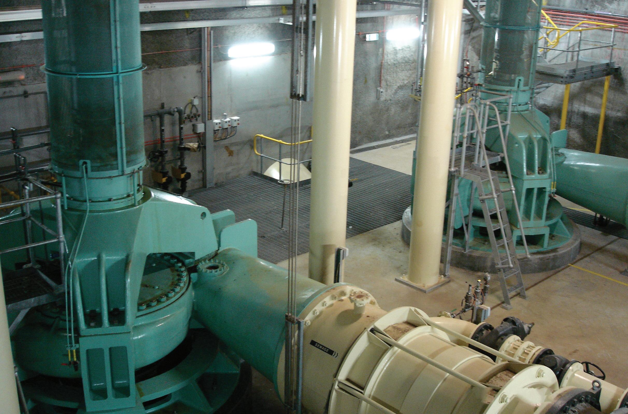
obtain highly reliable and serviceable equipment. We can achieve this by being very specific about technical requirements or by having performance based specification. The latter approach can’t be assessed until some considerable time has elapsed. The first approach is preferred as we already have considerable experience on pumping facilities. It is important to ensure we obtain a full understanding of all the operational and reliability requirements in conjunction with the physical and environmental conditions before considering any possible selections, as this may narrow the possibilities and ensure we get it right
and challenges with industrial issues, it did highlight to me that as an Engineer I prefer the technical aspect of my work. What types of pumps have you worked with?
I have come across most types of pumps within the water and wastewater market ranging from a couple of kW to several thousand kW and from progressive cavity, submersible, borehole, selfpriming, BPO, split case, vertical turbine, archimedes screw and canned pumps and with power from various sources such as electric motors, diesel/natural gas engines and hydraulic motors.
One of the more unusual installations is four vertical turbine effluent pumps at our Bondi STP powered by a 1 MW fixed speed motors driving through planetary gearboxes then a variable speed hydraulic couplings with their associated
up front, reducing the overall cost and time on selection.
For larger equipment in particular you can’t afford to ignore any of the mechanical, hydraulic or electrical aspects when getting down to the nitty gritty of selection “as the devil is in the detail”.
In addition to usual head and flow conditions other criteria to be considered are:
• Minimum and maximum flow as % of Best Efficiency Point BEP to prevent recirculation
• Minimum speeds to ensure adequate air flow for cooling and
oil supply and cooling systems. They have an on line vibration and temperature monitoring system for most bearings in the drive train.
We had two pumps installed at WPS174 at Burrawang pumping station which comprise a 2 metre diameter discharge vertical turbine pump and a fixed speed 4 MW motor weighing 40 Tonne and a 12 Tonne flywheel (to minimise water hammer). Due to cavitation damage the impeller had to be replaced. To minimise costs and time requirement the wet well was isolated and dewatered, the impeller was removed with the pump in situ. The wet well was then re-flooded and the impeller floated out through the inlet channel with the aide of divers.
We have had to carry out considerable modifications to the three 700 l/s archimedes screw pumps at our St Marys STP
INTERVIEW 36
Units 5 and 6 Raw Sewage pumps at North Head STP.


lubrication films for bearings
• Sufficient NPSHa margin above NPSHr (3% head drop – derived from testing) to ensure minimal impact as cavitation will commence at NPSHi, which will be higher than NPSHr.
• Set realistic noise and vibration limits which are related to the size, installation configuration and service conditions.
One of the most common misconceptions by operators is that variable speed centrifugal pumps can operate from near zero to full flow without impacting
to achieve improved reliability after the elimination of older asbestos material in the lower pump bearing and replacement with the synthetic alternatives offering completely different properties.
Outside the water industry I have been associated with diesel and electric fire pumps with controls to meet NFPA and Australian Standards, centrifugal pumps to meet API610 specification for petroleum industry requirements and pumps to military specification. These latter pumps can start life as a simple centrifugal design which, in a production environment, may cost say $5,000 and end up being $500,000 to meet the stringent design and quality control requirements.
How has pump technology and applications changed throughout your career?
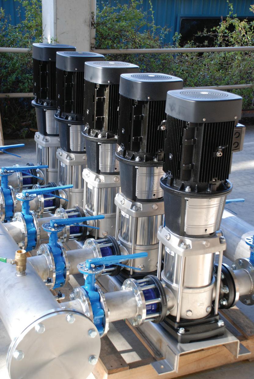

on the reliability. There is a maximum flow turndown ratio that can be achieved based on the individual pump design. How important is energy efficiency and how does it factor into decisions?
Sydney Water has an energy management unit and is extremely focussed on reduction in both energy usage and more importantly power cost.
It is Sydney Water policy to always use high efficiency motors and operate pumps to obtain minimum specific energy (kWhrs/kl) through detailed
Similar to most other equipment the pumps used were designed and built in Australia by Australian companies and in most cases, were engineered specifically to meet each customers’ requirements, whereas the pumps supplied now are mass produced in Europe and more commonly in Asia.
Based on total lifecycle costing analysis and with the development of larger submersible pumps Sydney Water has transitioned from the conventional sewage split case pumps to only use dry mounted submersible pumps where ever possible for renewals. Similarly larger sewage stations currently in design or construction will now be of wet well submersible type due to substantial cost savings.
There has been some minor improvement in pump efficiency, but the major
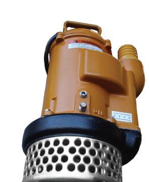

37 INTERVIEW
• Package Pump Stations • Water Transfer • Full Custom Design • Dewatering Submersibles • Air Blowers and Aerators Unit 6, Marina Close Mt Kuring-Gai, NSW 2080 P: (02) 9457 8622 F: (02) 9457 9891 E: sales@pumpserv.com www.pumpserv.com Extensive professional pumps industry knowledge attained through years of hands on experience.
Conversion from conventional Splitcase to dry mounted submersible pumps at SP0112.

analysis and system monitoring.
In conjunction with purchase price the power costs are also factored into the evaluation formula used where competitive offers are received.
How important are the maintenance and repair schedule and costs in project planning?
When developing our business renewal plans and options for creation of new
changes have been the reduction in the size of the pump by operating at higher speeds and velocities to achieve the same performance at reduced relative capital cost. There was a trend for solids handling application with the smaller pumps to an increased possibility of impeller choking which in turn has required more sophisticated impeller designs to compensate.
With the advent of Computational Fluid Dynamics (CFD) software sump and pump designs can now be carried out on the computer with very accurate results whereas pump designed previously were based on known tested designs which are either scaled up or down and previous sump design were model tested.
Other important changes have been the relative cost effective and use of variable speed drives which can provide substantial improvement in operating flexibility, size of operating wet well/reservoirs, reduction in capital and operating costs.
Earlier vertical pump installations were very much hit and miss with regard natural frequency of the pump unit structure. It was unlikely that there would
facilities an economic model is prepared which considers and compare the total life cycle costs over a 20 year period.
To my knowledge Capitalised cost calculation are not used.
Our design standard requires pumps to have a minimum life of 25 years but generally we achieve significantly longer life for larger conventional pumps, typically 40 years plus. Other component design life is:
be a problem with fixed speed pumps, however, with use of variable speed pumps there is a much higher chance that the natural frequency will lie within the operating range. With the advent of modal analysis software allows these problem areas to be identified early and designed out.
All of the major suppliers now provide either online or standalone pump selection programs to aide pump selection, placing all the performance and pump technical information for standard production pumps at the designers finger tips for the various alternatives.
With increased availability of more advanced material and development of new protective coating systems, we are now able to refurbish pump to achieve much longer periods between overhauls.
With cost limits per household placed on capital cost to provide sewage systems in outlying areas of Sydney, the use of traditional gravity sewage system have been replaced with low pressure systems which require substantial requirements for maintenance with tanks and pumps located at each property.
• Civil structures – 100 years
• Valves – 30 years
• Pipework – 50 years
• Motor and power system – 25 years
• Instrumentation and controls – 15 years
So within the total life of a facility the pump, moor, starters and controls may be replaced 2 or 3 times.
In most installations the total operating and maintenance cost will be significantly greater than the purchase costs and therefore have a significant impact on the evaluation.
Can you explain a bit about your on-site servicing and routine maintenance?
Up to now the facility maintenance was split approx. 50/50 between our own internal resources and external service provider. Staring from 1 July 2013 all of the maintenance will be carried out by a single contractor.
We have been reviewing our maintenance plans using Preventative Maintenance Optimisation (PMO) process which utilises both the considerable history of maintenance management systems and experience of engineering and field personnel.
Depending on the type of equipment
What is your current role?
My current role is not that far removed from the where I started 1987, in as much as I have a team of technical specialists working in the High Voltage, Instrumentation & Controls and of course, Pumping Support. We provide necessary input into development of specifications, scoping for replacement facility assets, design reviews, troubleshooting, commissioning and field testing of new pumping equipment including hydraulic systems. There is now an increased focus on commercial and safety aspects in all parts of the business.
I didn’t specifically choose pumps but as opportunities arose which lead me in the pump direction. As with more experience you gain once you are on a path it’s difficult to start again at the bottom in a different direction. There was then a natural progression into the positions which followed.
It’s nice to have the knowledge that you are contributing to improving the business operation. I have not regretted working in this industry and have thoroughly enjoyed this field of expertise.
38
INTERVIEW
Refurbished pumps with new motors at WP0001.
and level of criticality the maintenance can be “do nothing” (run to fail), periodic which is predominately time based, whereas on other high cost critical assets the maintenance plans are based on condition using parameters such as performance ie pressure and flow etc or symptom indicators such as vibration and temperature etc.
How do you monitor plant performance and correct performance deterioration?
For pumps of 600 kW or larger we usually have permanent online vibration and temperature protection system installed.
Level 2 condition monitoring (hand held) readings are taken (usually monthly) by a specialist contractor on less critical equipment and downloaded into a separate analysis software system. Reports are generated identifying any issues with recommendation for maintenance.
Equipment performance is usually monitored using either IICATS for network assets or SCADA at treatment facilities. Alarms can be setup around normal conditions or report generated to trend data over time with either of these methods used to trigger further analysis or a maintenance request.
Relationships with the pump industry
As we have devolved a majority of our non-operational aspect of the organisation to contractors we have needed to develop newer standards and specification which clearly identify our requirements. This process is ongoing. These documents become the starting point for defining the outcomes for new assets and equipment. We have established procedural and documents requirements with defined hold points for review. There are kick-off, CHAIR, HAZOP,CHAZOP and regular progress meetings with developers, project managers, designers, constructor and in some cases the suppliers. The discussion between supplier and designers usually takes place during the planning and detailed design phases.
Do you maintain a regular liaison with pump suppliers to update technology?
The Australian pump suppliers are usually keen to keep us up to date with their latest developments and will arrange a presentation specifically for Sydney Water or invite us to trade launches. In other situations where we become aware of new developments and products we will invite them to do a presentation to our operation, engineering and maintenance personnel.
How important is “made in Australia”?
Unfortunately, as has been the trend for some years, there are only a couple of pump vendors who can supply a limited range of competitive, locally manufactured centrifugal pumps. As a consequence we have been relying on local branches of the large multinational pump manufacturers to provide most of our requirements as there are no defendable preference for local manufacturers within our procurement policy.
Are you satisfied with the level of service provided by Australian companies?
There are several independent servicing workshops we rely on for repair of conventional pumps as well as the multinational suppliers servicing capabilities for those and the other current pump ranges. A majority of these companies provide a very good level of service.
What would you like to see improve?
To develop fixed price agreement for repair for standard pumps which includes long term spare parts pricing to obtain consistency and help reduce our administrative costs.
How important is ready availability of spare parts?
With the introduction of customer supply guarantees and licence agreements with the EPA has meant that we had to provide increased contingency plans for significant equipment failure and reduced our response time to minimise the impact to both the customers and environment. In addition to having an installed standby pump unit and to help minimise these impacts, we have a store or of around 100 submersible pumps to act as a rotatable unit. For the larger
split case pumps we generally have a complete rotating element. Therefore the need to obtain spare parts readily was somewhat reduced. However, we still see a need to be able to source spare occasionally for emergency breakdown and to enable planned pump overhauls for equipment where spares are for current models. For pumps which are no longer in production we rely on a pool of external engineering support workshops to manufacture most parts. Where new casings or impellers (repair cost greater than 70% of new pump price) are required, then it’s time to replace the whole pump.
What are the most important issues in pumps today?
From a consumer perspective we need to ensure that there is viable competition across the product spectrum by supporting at least two vendors in each product type. Where there is a unique product we should consider forming an alliance with them where we possibly work closely in product development and have an open book pricing agreement.
It is essential that the vendor provide a reasonable level of technical capability locally to support the Australian market.
Where do you see the pump industry going in the future?
As has been the trend, the takeover by the larger multinational companies of all the smaller manufacturers will continue where nearly all the engineering and manufacturing is outside Australia except for a few smaller low volume products.
Within these larger companies comes a range of other products so they are able to offer packages which include motor starters and control system etc as well as complete packaged pump stations for water supply and sewage systems.

39
TEPS pump station at St Marys STP with 4 Archimedian screw pumps – one enclosed screw (right) the other three are open screw type.
Modernising an Australian
The Snowy Mountains Hydro-electric Scheme is one of Australia’s most iconic engineering achievements. Completed in 1974, the scheme is now undergoing a $400 million modernisation program. The program is introducing advanced controls and protection systems technology across the entire Scheme. Ageing and high maintenance plant components such as circuit breakers, high voltage transformers and cables are being replaced with modern components. New turbine runners are optimising generation capabilities and improving efficiency of water utilisation and the Jindabyne Pumping Station is being upgraded.
Major maintenance of the Scheme’s extensive transmountain tunnel systems, which deliver water from lakes to the power stations, is in progress to ensure the ongoing safe and reliable management of water utilised by the Snowy Mountains Scheme. Innovative maintenance techniques and engineering solutions for water conveyance tunnels are enabling future tunnel maintenance requirements to be substantially reduced.
2012 saw the completion of work in the Kosciuszko region. Jindabyne Pumping Station pumping units had their control and protection systems upgraded, In addition in 2012 Guthega Power Station, the oldest power station in Snowy Hydro’s fleet was also completed with the upgrade of its second generating unit. The outage of this unit commenced in late February and return to service occurred in August 2012. Unit 1 having been successfully upgraded in 2010.
The major works in the Lower Tumut region were completed in 2011. The six generating units at Tumut 3, the largest Power Station in the Snowy Hydro fleet have all been modernised and upgraded with the turbine runners replaced, new governing, control and protection systems installed and all other mechanical and electrical components overhauled. The upgraded units at Tumut 3 are now capable of providing between 25 and 50MW of additional capacity each. Blowering Power Station control, protection, governor and excitation systems were replaced in 2009 to provide reliable remote operation.
Twenty one air-blast generator circuit breakers across the Scheme have now been replaced with modern reliable SF6 insulated breakers. The new breakers reduce maintenance requirements, increase overall availability, and improve reliability. In addition, all 11kV distribution circuit breakers across the Scheme have been replaced.

PROJECTS 40
an Australian icon
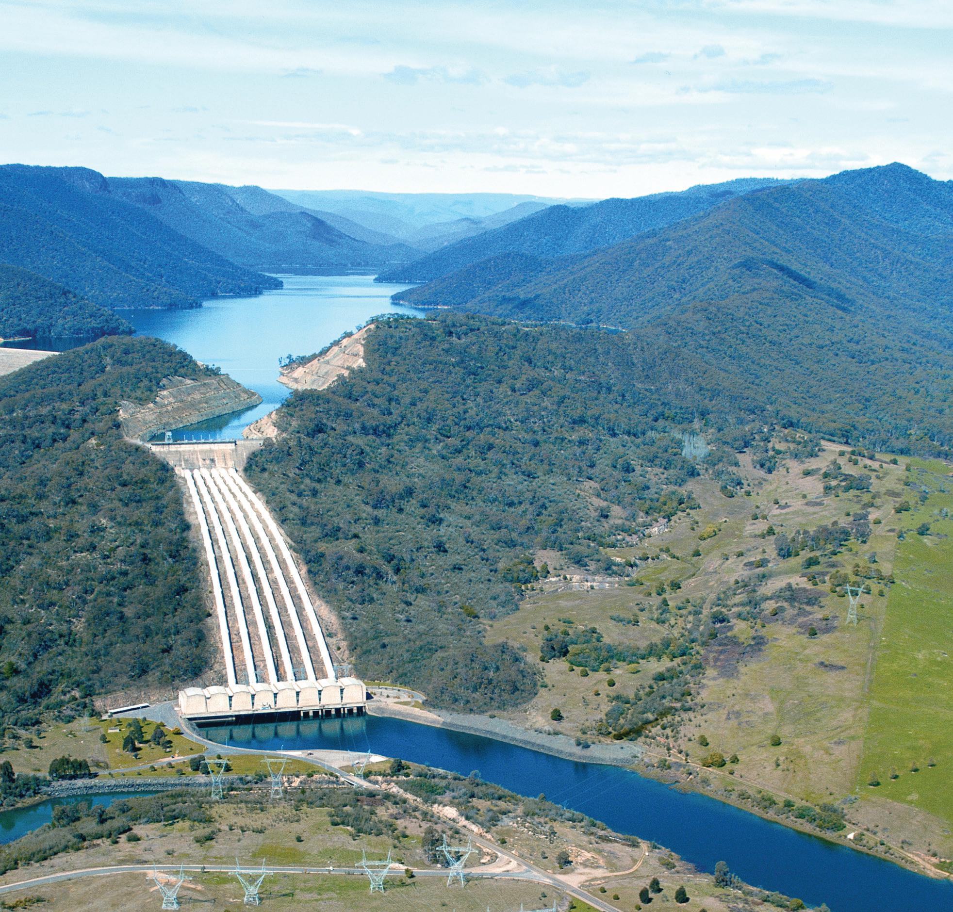
PROJECTS

About the scheme
The Snowy Mountains Hydro-electric Scheme is one of the most complex integrated water and hydro-electric power schemes in the world.
The Scheme collects and stores the water that would normally flow east and diverts it through trans-mountain tunnels and power stations. The water is then released into the Murray and Murrumbidgee Rivers for irrigation.
The Scheme took 25 years to build and was completed in 1974. More than 100,000 people from over 30 countries came to work in the mountains to make true a vision of diverting water to farms to feed a growing nation and to build power stations to generate renewable electricity for homes and industries.
Sixteen major dams, seven major power stations (two underground), a pumping station, 145 kms of inter-connected trans-mountain tunnels and 80 kms of aqueducts were constructed. Even before the Scheme was completed, it was named as one of the civil engineering wonders of the modern world.
The Snowy Mountains Scheme on average produces around 4,500 gigawatt hours each year of clean renewable energy for the National Electricity Market. In doing so, the Scheme prevents around 4,500,000 tonnes of Carbon Dioxide being released each year. That’s the equivalent of the exhaust from around 1 million cars.
Snowy Hydro is constantly exploring ways to enhance the Scheme through
Detailed planning work has now commenced for the Upper Tumut project phase. The works associated with the replacement of main transformers and 330kV cables for Tumut 1 underground Power Station is underway and the first four transformer replacements have been successfully completed. The replacement of the fifth transformer has commenced with remaining transformers to be replaced over the coming months.
Delivery of all four new turbine runners for Tumut 2 Power Station has occurred. The first of Tumut 1 turbine runners is arriving in early 2013 with the delivery of the remaining runners for Tumut 1 occurring over the next 12 months, prior to the scheduled outages commencing in 2014.
The initial unit upgraded in the Murray region, Unit 14 at Murray 2 Power Station was completed in early 2008. 2012 has seen a return to the region with the controls and protection upgrades in Murray 1 with Unit 8 completed in December 2012 and Unit 7 returning to service in early 2013. The control and protection upgrade outages at Murray 1 will continue through 2013, and 2014 until early 2015 when the last controls and protection upgrade and the first mechanical refurbishments of the Murray 1 Power Station is planned to take place. The contract for the design and purchase of the Murray 1 turbine runners has been signed with design of the first turbine runner under way and delivery of the first runner is scheduled to occur in February 2015 prior to commencement of the first mechanical upgrade outage.
the addition of mini hydros at Tumut 3, Jindabyne and Jounama and upgrades of the existing operating plant.
The Scheme is operated and maintained by Snowy Hydro Limited.
Today, Snowy Hydro continues to play a vital role in the growth and the development of Australia’s national economy, by diverting water that underwrites over $3 billion in agricultural produce and by generating clean renewable energy.
Snowy Hydro currently provides around 40% of all renewable energy that is available to the eastern mainland grid of Australia, as well as providing fast response power to light up the morning and evening rush hours of Sydney, Brisbane, Canberra, Melbourne and Adelaide.
42
PROJECTS
Tumut 3 Power Station
Pumping Station
The Snowy Mountains Scheme has one pumping station at Jindabyne and a pump storage facility at Tumut 3 Power Station. Jindabyne Pumping Station pumps water from Lake Jindabyne through the Jindabyne-Island Bend Tunnel to the Snowy-Geehi Tunnel at Island Bend and was completed in 1969.
The two pump sets at Jindabyne consist of a 25.4 MW synchronous centrifugal Pump capable of pumping 12.7 m3/sec at 189.3m head and an associated a 6.7 MW Induction motor booster/lift pump which pumps 12.7m3/sec at 48.8m head.
The upgrades focussed on improved condition monitoring to reduce maintenance costs and saw substantial improvements with the control, instrumentation and monitoring systems, mechanical and electrical protection relays and actuating devices and all associated cabling all being upgraded. Excitation systems were also replaced as part of the upgrade.
A Rockwell Control Logix system is now in place, supported by Areva and GE Relays for protection as well as various other field instrumentation.
The upgrades were carefully time to ensure the outage duration fit within the pumping regime.
The upgrades will provide a reliable and maintainable control system for motor control and starting as well as duplication of the protection systems to increase level of protection.
All of the major overhauls and upgrades have all been completed without significant injury or incident. Outstanding teamwork, dedication, and skill has been displayed by all involved, contributing to the successful implementation of a complex, high quality finished product. The project represents an investment in maximising asset value through increasing turbine capacity and efficiency, maintaining long term reliable operational capability and modernising the Scheme assets through replacing ageing technology.
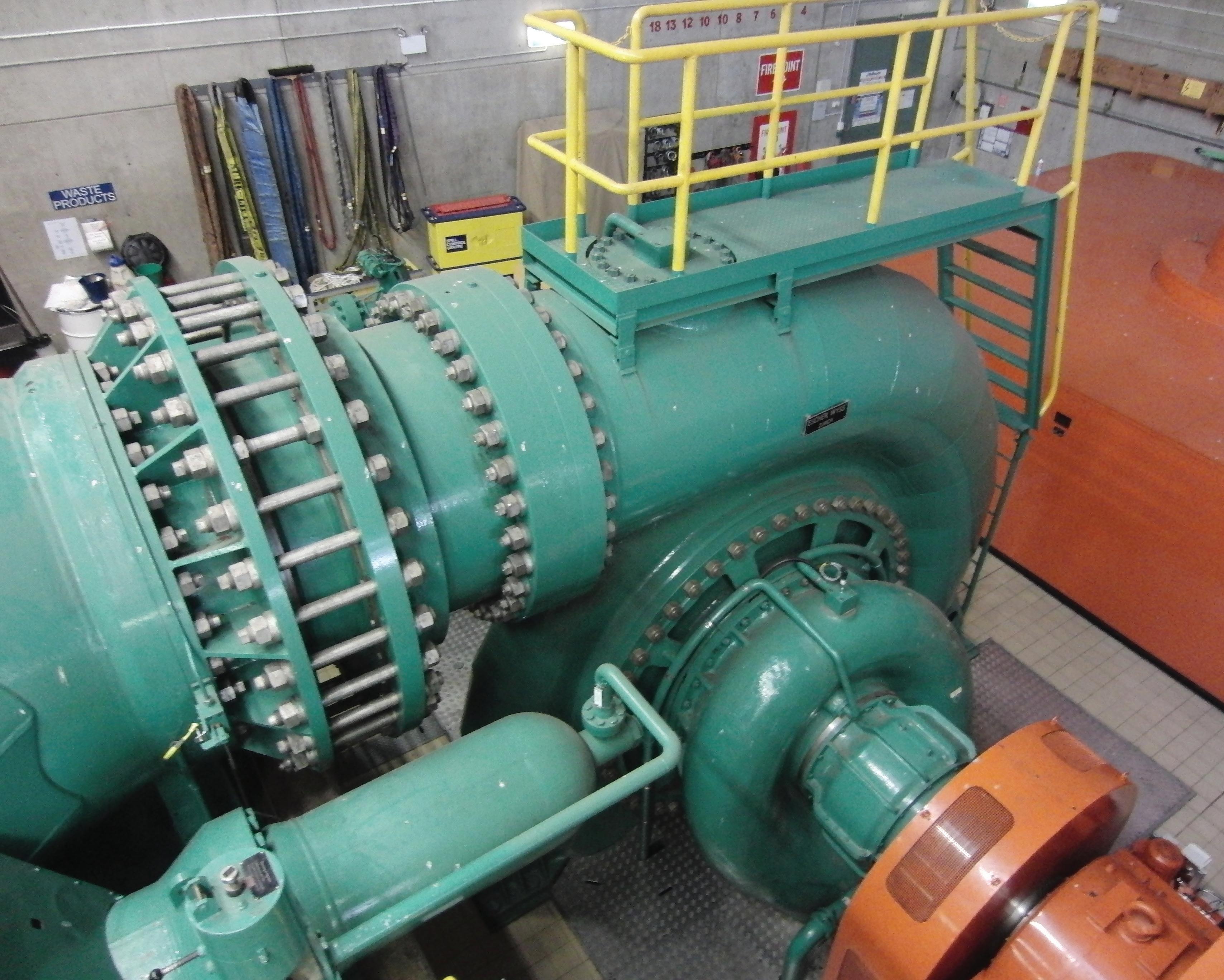
43
PROJECTS
The Jindabyne Pumping Station
Innovation for water pumping station
Paringa is a small town in the Riverland area of South Australia famous for its vineyards, almond, citrus and stone fruit orchards. The area lies north of the Barossa Valley region – one of Australia’s most famous wine regions.

Water is a vital resource in the Riverland area where summers are dominated by hot dry days.
Over the last five years, the region has been subject to strict water restrictions imposed by drought conditions. Water is pumped out of the nearby Murray River to irrigate the area. Actions to achieve water use efficiency are paramount in this region, while pumped water is subject to stringent restrictions imposed by local authorities.
ABB value provider GH Electrical, based in Mildura, have been working with local authorities to engineer a suitable solution for the Paringa pumping station, which provides water to this region. Additional pumps have been installed, major upgrades have been implemented including installation of dual pumps and improved control systems, contributing to overall improvement of pump station capacity.
The most energy efficient and cost effective solution was to install a special application on two pumps.
Rather than using a traditional solution of two frequency drives for the two pumps, just one frequency drive was
Fact file
1 x ABB drive ACS800-01-205 160 kw 254 Amp
1 x ABB RSYC-0 synchronising module
2 x 150kw 4pole motors driving 2 x Kelly & Lewis pumps into common manifold with 20m rising main plus 5.6 km pipeline at approximately 600 kpa
1 x ABB PLC AC500-eCo
1 x passive harmonic filter
44
PROJECTS

designed together with a synchronous by-pass. The synchronous bypass uses one frequency drive to control one pump up to speed - putting that pump directly on line – allowing the frequency
converter to control the second pump. Overall, the application drives a sizeable 300 kW pump motor. An ABB single drive and two pump motors regulate the flow pressure. The synchronizing unit is coupled together using ABB smart electronics, low voltage components and a PLC unit which takes care of the special starting phase.
The ABB variable frequency drive ramps all the motors up to speed at a controlled rate, minimizing the inrush current required by each motor at startup.
The variable frequency drive ensures that the two units are operated at the desired speed, thus avoiding over compensation from the network or more than one unit carrying more than its design load level – which would adversely affect harmonic levels on the local network.
Since this pumping station is close to a residential area, there was also need to reduce noise and electrical energy interference issues that had occurred over the years when the huge pumps were started. To reduce electrical noise, the team at GH Electrical applied ABB
harmonic filtering. This solution also adheres to stringent requirements from the local power supply authority with regard to starting currents, harmonic levels and possible voltage drops on the network.
GH Electrical have plenty of experience with pumping stations and irrigation systems. Their specialist knowledge and expertise has provided an ABB solution that is not only acceptable to local authorities but also to the many residents who rely on energy and water in this rural environment. An environment close to the Barossa Valley famous for it a major wine producing area and tourism destination.

Water and wastewater utilities are facing many challenges from managing leakage and pressure, optimizing pump performance, improving potable water quality, reducing energy consumption and CO 2 emissions to lowering maintenance costs. ABB’s drives, motors and PLCs are designed to help motor-driven applications such as pumps, fans, compressors and conveyors, tackle these, and other, challenges. To discover how to improve your utility’s energy efficiency and productivity, visit www.abb.com/water
45
Optimize
compromising energy
ABB Australia Pty Limited Tel. 1800 222 435 www.abbaustralia.com.au/productguide PROJECTS For more information please contact: G.H. Electrical Contracting and Automation Mildura, Victoria, 3500 Phone: (03) 5023 1652 or (03) 5023 3441 or ABB Australia Pty Limited Tel: 1800 222 435 Email: drives@au.abb.com www.abbaustralia.com.au
process performance without
efficiency.
Local capability key to emergency mine dewatering

In June 2012 Gippsland in Eastern Victoria faced some of the worst floods in recent memory. On June 6, the Morwell River dramatically burst its banks, sending floodwaters into the Yallourn open cut coal mine, damaging a coal conveyor and slowing production, then two weeks later, the mine flooded again, further affecting production - and threatening Victoria’s power supply.
The mine is Australia’s second largest open cut mine and is adjacent to the Yallourn power station, where it provides continuous source of fuel for generation at the Yallourn Power Station, which is responsible for nearly 22% of Victoria’s electricity consumption. The power station owner, TRU Energy, now known as Energy Australia, had to mobilise fast to clear the water out of the mine and maintain a reliable electricity supply.
TRU Energy secured environmental approval from the EPA and quickly set to work to divert the Morwell River through 3.5 kilometres of pipe into the LaTrobe River.
But the first order of business was getting the water out of the mine at a faster rate than it was coming in. Dewatering pumps were installed at the bottom of the mine to pump the water out. The set-up
required a large number of dewatering pumps and Coates Hire, Kennards Hire, Link Pumps and Bridge Pumps were all able to quickly supply what was needed.
Before a large diameter pipeline could be installed, TRUEnergy urgently needed a fast solution to carry the water out of the mines - that solution was layflat hose, and they needed a lot of it and quickly.
Fortunately Crusader Hose, one of the world’s leading suppliers of layflat hose, manufactures their entire product locally in Melbourne. The team at Crusader were able to swing quickly into action, delivering the required product. Layflat hose has the advantage of being able to be deployed very quickly and in next to no time was carrying the water out of the mines. Layflat hose is able to successfully
46

pump at 10 bar operating pressures without problems.
In all, Crusader supplied 4800m of 8” Heavy duty layflat hose, safely getting the dewatering operation through its first two months by which time TRU Energy had installed a large 1.60m diameter, 3.5 km long pipeline, supplied by Resource Equipment Ltd (REL).
Commenting on the works in July 2012, TRUEnergy Group Executive Manager Operations and Construction, Michael Hutchinson, said “The partial diversion of the Morwell River is a major milestone in our recovery work. This work, combined with reduced rainfall and river flow, has meant we are now able to pump more water from the mine than what is coming in. While the flows will remain dependent on the weather, this is a fantastic achievement.”
At this stage, they were able to get the required flows through the large pipeline and the layflat was decommissioned.
“It’s been an extraordinary effort by the workers who, despite facing some cold and wet conditions, have been committed to restoring the mine and power station to full capacity” said Michael Hutchison. With its work done, the Crusader layflat hose was rewound and it is able to be redeployed again.
In commenting on the success of the dewatering project, the Managing Director of Crusader Hose, Mr Francois Steverlynck said “We understood the
challenge of the mine to get back into operational capability and hence mobilised our entire factory staff to assemble couplings onto all the layflat hose. We used a very secure wire whipping method to ensure that the couplings would not blow off and to the credit of all staff, not one did!”
This quick response to the emergency mine dewatering ensured that Victoria’s electricity supply was maintained and shows the benefits of that local manufacturers can provide in an emergency.


WATERLORD WATERLORD

47
Australia’s leading manufacturer of layflat hose 22 Industry Place Bayswater VIC 3153 Australia Telephone: +61 3 9720 1100 Email: sales@crusaderhose.com.au www.crusaderhose.com.au MINE DEWATERING HOSE
Gosford council’s sewage pump station upgrade program
Gosford City Council, on the New South Wales Central Coast, is currently investing between five and seven million dollars each year to improve the performance of many of its 185 sewage pump stations. Since 2009 over 40 of its ageing pump stations have been completely upgraded, refurbished or seen their pumps replaced, and works are either underway or planned at more than 20 other stations.
Program overview
The Council’s Sewage Pump Station Upgrade Program is an important part of its efforts to protect the local community and environment against sewer overflows and odours by improving the reliability, capacity and performance of the region’s sewer network.
“A number of pump stations have been operating for over 30 years. So the program’s first step was to carry out condition assessments at all 185 stations to identify those needing highpriority upgrade works,” says the Council’s Senior Project Delivery Engineer,
Mark Losurdo, who is responsible for overseeing the program’s delivery.
“Replacing ageing parts and equipment, including each station’s pumps, is helping us improve current service levels across the network and cater for extra demand as the population grows.”
The program’s significant investment is also ensuring the Council’s pump stations continue operating to a standard that complies with the environment protection licence issued by the New South Wales Environment Protection Authority and does not pose a safety risk to operational staff or the community.

Pump replacement works
Over the past three years almost 65 pumps have been replaced at 40 pump stations as part of the Council’s program and a further 22 pumps across a number of other stations are expected to be replaced in the next twelve months.
“The pumps we’ve replaced so far have been operating for between 12 and 35 years,” Mr Losurdo explains.
“There’s certainly no ‘one pump fits all’ in our network. We operate a large number of pump stations due to the region’s diverse topography and widely distributed population and this means the size and number of pumps at any particular station also varies significantly.
“Many of our pump stations only service small populations and typically might operate two small 2.4kW pumps. On the other hand some of our pump stations service much larger suburbs and need to pump over high ridgelines. In cases like this up to four large 200 kW pumps are needed.”
Pump replacement works are a key part of the Council’s program, along with increasing the storage capacity of a number of pump stations, improving their odour control systems and upgrading electrical, telemetry and other mechanical components.
Earlier condition assessments showed each pump station has its own particular upgrade requirements but generally, the Council’s program mostly involves the replacement of existing centrifugal pumps with new similar pumps.
PROJECTS 48
‘The major sewage pump station servicing the Gosford CBD has undergone a $2.6 million upgrade as part of the Council’s program.’

“Our preference has been to stick with submersible electric centrifugal pumps, mainly because of their reliability, cost effectiveness and low maintenance requirements. This approach has also given us the flexibility to introduce incremental increases to a pump’s capacity if needed,” Mr Losurdo says.
“Improvements with these pumps over time have seen a reduction in the amount of energy needed to pump the required duty and more sophisticated technology now allows us to monitor each pump’s performance more closely.”
To date the Council is pleased with the performance of the newly installed pumps.
Program challenges
“We expect the level of salt water that infiltrates our network, given its coastal location, has shortened the life of our existing pumps in many cases. This is an issue that we have looked to address when installing the new pumps and continue to tackle via other upgrade and rehabilitation works,” Mr Losurdo says.
“With the supply of new pumps there’s always the challenge of balancing project lead times around their delivery and making sure proper witness testing of their operation is completed before Council accepts them. Plus, by-passing each pump station while construction proceeds is always a delicate and complex process.”
Gosford City Council’s Sewer Network (at a glance)
The Council transports, treats and disposes of sewage for:
• around 157,000 people
• over 65,000 residential properties
• around 3,000 businesses and public places
The Council transports the region’s sewage using:
• around 1,500 kilometres of sewer mains (primarily gravity based)
• over 180 sewage pump stations
The Council treats the region’s sewage at its two sewage treatment plants in Kincumber and Woy Woy.
The Council disposes of treated effluent via the Winney Bay ocean outfall between Copacabana and Avoca Beach.
Program status
Another pump station refurbishment has recently been completed. The construction of a new sewage pump station and the refurbishment/upgrade of five other stations is underway and expected to be completed this year.
Four other pump station projects will also start this year, and design activities for required works at another six stations are currently underway.
More information is available at www.gosford.nsw.gov.au
49 PROJECTS
Around 24 wet wells have been completely restored. including pump replacement works
The Australian office building market
The total occupied space for office buildings in Australia is estimated at approximately 21.0 million square metres (sqm). While government offices account for 21.9 percent of this total office space, the majority (78.1 percent or 16.4 million sqm) is commercial office buildings. The global financial crisis and more recent weaker economic conditions have severely affected investment in the Australian commercial building market. The market expects a return to trend economic growth in 2012-2013, underpinned by further growth in tenant demand. Apart from limited new supply, low vacancy levels are expected, particularly for prime grade offices (which are the most environmental friendly commercial buildings). This presents considerable opportunity for rent rises for owners and investors. Despite the strength of the Australian dollar, offshore investors continue to show strong interest in the Australian commercial property market. In terms of pumps used in office buildings, the refurbishment market is expected to be the key driver for pumps market revenue growth in the near term because investments in new office building construction is likely to be below trend in 2013-14.
The green building market
Commercial and government office space across the country account for 10.0 percent of Australia’s greenhouse emissions. This makes the office building sector a key area of focus for improving environmental outcomes at a total level.
The property industry in Australia has witnessed significant developments in relation to sustainability in recent years. This has been driven at all levels—the individual property level, as well as the corporate and the external environment level (e.g., legislation, standards, government incentives, environmental costs, and customer demand).
Australia’s Commercial Building Disclosure program commenced in November 2011. According to this program, all sellers and lessors of office space of 2,000 square meters or more are required to obtain and disclose a current Building Energy Efficiency Certificate (BEEC). Such a certificate allows the
NABERS Energy star rating for the building, general energy efficiency guidance, and an assessment of tenancy lighting in the area of the building that is being sold or leased. As a national program, the goal is to improve the energy efficiency of Australia’s largest office buildings. It also provides more transparency to make informed decisions while renting office space.
The establishment of green building rating schemes in Australia has been a key success factor of the green building agenda. The “Green Star” and “NABERS” rating schemes are the two major key initiatives to evaluate the environmental design and environmental performance of office buildings. They encompass a range of office building criteria, cover various property types, and are comparable to the international green building benchmarks in the U.S. and the U.K. Both rating schemes have been actively supported by the property industry in
Australia and have, over time, transformed Australia’s property and construction markets.
A ‘rated’ building is considered “premium” office accommodation, and is more likely to deliver benefits such as a higher return on investment, reduced vacancies, and higher face rents (the quoted rent before taking into account incentives or increases).
Opportunities for the pump industry
The addressable opportunity for pump suppliers to office buildings is typically across applications such as water boosting, circulation, drainage and waste, fire fighting as well as metering or dosing.
The ongoing challenge of high price sensitivity among customers in the building services industry is expected to lead to more competitive pricing by pump manufacturers.
HVAC 50
However, key office building trends translate into specific drivers of pump market demand. For example, recycling and reuse of water in office buildings helps drive demand for booster pumps for water transfer as well as metering pumps for chemical dosing (to treat water). Reduced town mains pressure may spur demand for larger fire fighting pumps. Increased focus on occupational health awareness will boost demand for metering pumps for dispensing chemicals in cooling towers. Retrofitting HVAC systems to raise ‘green’ performance will drive demand for more energy-efficient circulator pumps. Right sizing of motors and minimization of leaks (as part of overall system efficiency improvement) will help grow service revenues for pumps across most applications.
In fact, there is a significant opportunity to educate and engage customers on the criticality of regular and appropriate maintenance of pump systems. This service market has considerable untapped potential since the frequency and adequacy of pump maintenance in office buildings is currently well below optimum levels.
The shift to activity based workplace design and ‘smart buildings’ will eventually lead to increased demand for
intelligent pumps. In 2012, the median workspace ratio for office buildings was around 14.0 sqm per person across Australia, down from 17.6 sqm in 2008. The push to improve workspace efficiency and smarter workplace design – particularly open plan formats - is the prime driver for this decreasing trend. In the context of the drive for improved efficiencies, pumps that provide increased energy savings in buildings are likely to see increased demand. Although the initial cost of installation of energy efficient pumps is high, it is more costeffective for end-users as the life cycle costs are significantly less, particularly as the price of traditional sources of energy continues to increase. The focus on efficiency is expected to be more on the whole system, rather than just the pump components. Increased demand for energy efficient pumps will result in pumps designed with more electronic features that would enable better system integration and system efficiency.
This Market Insight was authored by Ivan Fernandez, Industry Director, Australia & New Zealand, Industry Practice, Frost & Sullivan.

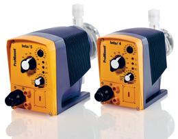

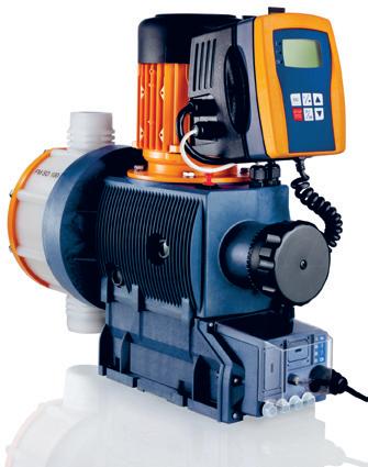
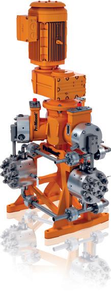
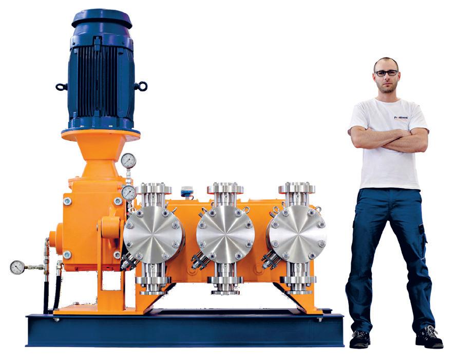


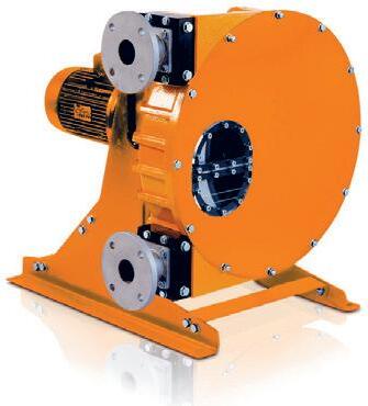
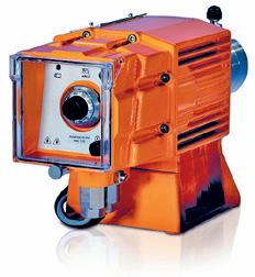

51
HVAC
more information, please email djeremiah@frost.com Chemical Metering and Transfer Equipment from ProMinent® for process and water treatment in the Mining, Oil and Gas Industry Solenoid and motor driven lower capacity metering pumps Process and flameproof metering pumps DULCOflex® hose and tube pumps, Spectra® PC pumps ProMinent Fluid Controls Pty Ltd Head office: Sydney (02) 9450 0995 Brisbane: (07) 3213 1900 Melbourne: (03) 8795 7430 www.prominentfluid.com.au High end metering pumps and dosing packages Pr o Minent ®
For media enquiries or
Pumps a key part of Darling Quarter’s sustainable success

Sega World in Sydney, Australia, was built in 1997 as the flagship tenant of the city’s tourism complex of Darling Harbour. It was designed and themed by gaming company Sega as one of several SegaWorld-branded amusement parks but even the 2000 Olympics couldn’t save it and it closed within four years. In 2003 the Sydney Harbour Foreshore Authority (SHFA) took the lease over the Sega World site at Darling Walk and in 2008 Lend Lease obtained the lease and demolished the Walk, replacing it over the next two years with a $500m mixed use project in a collaborative effort with the SHFA.
Now known as Darling Quarter, the development includes low-rise campus-style commercial buildings, known as Commonwealth Bank Place, and a family and leisure precinct with retail and dining options, a community green with a 4,000sqm playground and car park. Darling Quarter has reconnected the south end of Darling Harbour to the city of Sydney and Lend Lease has delivered an interactive work and play area for the local community, city workers and tourists. But the one important aspect of this project was Lend Lease’s determination to set the benchmark for a green precinct development in Australia.
52
The Grundfos solutions
While a combination of active and passive design features contributed to Lend Lease’s aim for a world-class green precinct, saving and recycling water would also help boost the chance for the elusive green star rating.
Darling Quarter saves a massive 92% on mains water consumption compared to conventional office buildings. This is achieved by a combination of black water treatment and reuse, employing sewer mining, and rainwater harvesting.
Both solutions feature Grundfos pumps and more than 50 Grundfos pumps are installed throughout Darling Quarter precinct. The selection of quality, Danish designed Grundfos pumps was made by the hydraulic consultants at Warren Smith & Partners and mechanical consultants at Arup in consultation with Lend Lease.
These include:
• Grundfos NB pumps for air conditioning circulation
• Grundfos Dual UPS (N) pumps for the hot water system
• Grundfos Hydro MPC for recycled water
• Grundfos Hydro MPC for cooling tower make up water
• Grundfos Hydro MPC for potable water
• Grundfos BM, SEG & CR pumps used in recycling of black water
• Grundfos SP pumps for rain-water reuse
• Grundfos SEG submersible pumps for sewage and stormwater pump outs

Demonstrating how modern, sustainable buildings can benefit the environment, the Darling Quarter on-site recycling water plant extracts sewage from the municipal sewer system.
The recycling plant is located in the basement of the Commonwealth Bank Place office buildings. Though only taking up 200m2 of space, the treatment plant treats 245 kilolitres of sewage a day, producing 166 kilolitres of treated water which is used for toilet flushing, irrigation and cooling tower make-up water.
The sewer mining infrastructure and recycled water treatment plant was designed by Warren Smith & Partners, supplied and installed by Veolia Water Solutions & Technologies Australia. Grundfos has installed factory assembled and tested pump sets and control panels. The pump sets consist of cast iron SEG grinder pumps for sewage and brine return to the municipal sewer main. Combined Grundfos BM booster pumps and CR centrifugal pumps are utilised in the treatment process.
For the irrigation of the public park and gardens, the Darling Quarter site also includes a rainwater harvesting system which was designed by Warren Smith & Partners and consists of a 300,000 litre underground tank, Grundfos BM and CR MPC pumps and treatment systems to collect rainwater.
Using rainwater allows Darling Quarter to help the SHFA to conserve its precious drinking water. In total, the rainwater reuse will save up to 60 million litres of drinking water per year.
The outcome
Lend Lease achieved its aim. Darling Quarter’s sustainable outcome was cemented by achieving a 6-star Green Star office V2 Design Rating.
Grundfos has played a major role in helping Lend Lease achieve this 6 star Green Star rating which recognises worldclass innovation.
The partnership between Grundfos, Warren Smith & Partners, ARUP and Lend Lease proved to deliver the most sustainable solution possible.
Steen Holm Jensen, Managing Director of Grundfos Pumps Australia, says: “The commercial building industry is looking to suppliers such as Grundfos to provide solutions that help achieve sustainable outcomes; both in terms of energy savings and reduced water use.
“We were delighted to have played a role in contributing to the environmental success of Darling Quarter.”
53
Centrifugal pump selection in the HVAC industry
The Australia n institute of Refrigeration, Air-conditioning and Heating (AIRAH) has recently developed a draft guideline for the selection and application of centrifugal pumps used in the building services industry for pumping water and other fluids. This article extracts some of that guideline.
The systems approach
Centrifugal pumps perform many important functions in environmental control systems. A pump provides the energy to move water and other fluids through piping, fittings and equipment, and is the heart of many HVAC&R systems. Proper pump design considers not just the pump but the entire pumping system, including the supply and demand sides of the system, and how the individual system components interact.
Best-practice centrifugal pump application in the HVAC&R industry requires practitioners to take a “systems approach” to pump selection, control, installation and commissioning. In a systems approach, attention shifts away from individual components to focus on total system performance.
Best practice pump application
• Document system operating conditions and system performance or outcome requirements
• Develop designs and design options that achieve the performance requirements or optimise the system outcomes
• Assess alternative designs and options, and select and document the option that provides the most benefit for the least cost
• Implement the selected option in accordance with the design documentation
• Assess installed system energy consumption and relate it to system performance
• Monitor and fine-tune the system over time
• Operate and maintain the system for optimum performance
• In particular, the pump selection, the pump connections to the distribution system and the method of pump control can have a significant impact on the system performance outcomes.
Selection information
Pumps are available in a range of volute and impeller combinations that meet the requirements of various pumping systems. Pump selection is the process of matching the characteristics of the pump to the requirements of the system. A pump should be selected to operate within the stable portion of the pump curve. Information required by pump manufacturers to enable them to select an appropriate pump includes:
• Constant or variable flow design basis
• Maximum and minimum flow rate or flow profile
• System operating pressure (head) at maximum and minimum flow rate
• System operating temperature band, maximum and minimum temperatures
• Static pressure (head) at pump location at no flow condition
• Details of the fluid to be pumped including density, viscosity, etc
• Whether the system is open or closed-circuit
• Whether the fluid contains any solid matter, e.g. mud, particulate
• Materials of construction, system and pump
• The drive and, if electric, the power supply available
• Any starting limitations of the power supply
• Environmental conditions of the pump location, including ambient temperature and altitude
• Type of motor and enclosure, e.g. open protected, totally enclosed, etc
• Preferred speed limitation (governed by best efficiency)
• Type of vibration isolation required (inertia base, rubber in shear, seismic or standard springs)
• Any special electric controls, e.g. integral VFD, thermistors in windings, thermal overload protection, etc
Centrifugal pump costs
When selecting centrifugal pumps, considerations should include life-cycle costs such as:
• First costs (purchase and installation)
• Ongoing costs
• Energy use
• Maintenance requirements
• Reliability requirements.
The power consumed by a pump is dependent on the operating duty and the motor selected, including the power needed for any drive and impeller losses.
System design and specification
Centrifugal pumps cannot be designed in isolation from the distribution system. Designers and centrifugal pump suppliers need to take a holistic “systems” approach to design.
System resistance calculations
For a fixed piping network there will be a specific relationship between the flow through the network, and the pressure (head) required to produce the flow, independent of the pump used. The first step in the design of any pumped system should be the construction of this pressure-capacity curve for the system, called the system curve. Accurate system resistance calculations are necessary if the centrifugal pump is to perform in accordance with the required system design.
It is recommended that calculation of the system resistance be carried out by estimating changes in total pressure throughout the system.
Effects of errors in estimating system resistance
An error in the system curve calculation may result in the selection of a pump that is sub-optimal for the system. For detailed information on calculating piping and fitting system resistance, refer to AIRAH DA16 Water piping for air conditioning.
HVAC 54
Safety factors
System designers sometimes apply “safety factors” to their estimate of the system resistance, to safeguard against inaccurate evaluation. On occasion, these safety factors may compensate for resistance losses that were overlooked, or for variations occurring during the installation process, and the actual system will deliver design flow. The usual result, however, is that the estimated system resistance, including the safety factors, is in excess of actual system resistance. Since the centrifugal pump was selected to design conditions, it will deliver more fluid because the actual system resistance at the design flow rate is less than design estimate.
This means the centrifugal pump will usually be operating at a less efficient point on the pump performance curve, and may require more power than would have been the case at design flow. It may also result in much higher noise levels. Under these conditions, it may be necessary to reduce the centrifugal pump speed or to increase the actual system resistance (e.g. adjust a valve) to the value determined in the design calculations.
Adding safety factors to an accurately designed and calculated system curve will generally result in an oversized pump. Adding subsequent safety margins to installed pumps and to the pump motors compounds the problem of oversizing. Safety factors applied by designers to allow for uncertainties should be documented within the system design documentation and these are the only factors or margins that should be applied to the pump.
It is essential that, when a safety factor is applied during the system design calculations, it is quantified and documented and the information made available to other stakeholders in the project. Designers in HVAC&R often use a safety factor in the order of 10 per cent.
Centrifugal pump surge
Surges or transient pressures occur in pumping systems when pumps start and stop, or when valves open and close quickly. Pressure surges can stress system pipes, valves and fittings – high pressure surges cause bursts, and low pressure surges cause collapses. Pressure surges can also cause water hammer, a loud and potentially destructive internal force that can generate significant vibration.
Electronic starting and stopping of the
pump motor is an effective part of the solution to system surge problems. An advantage of VFDs is the soft-starting characteristics of the associated electronics. Slow-acting valves are also a design solution that should be considered.
System hunting
The term “hunting” applies to an underdamped control circuit. Sensors can be used to control valves or motor speeds, but if the control system responds too quickly, it will overcorrect and have to readjust in the other direction. Hunting refers to the condition where the system is continually moving back and forth without finding a stable control point.
System stability
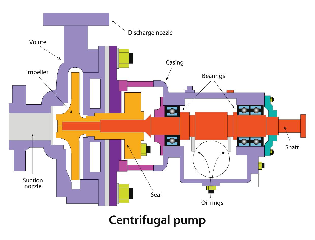
use variable speed control and no throttling valves or bypass lines
• Maintenance and management –consider system maintenance, filters and strainers, and automatic and remote monitoring systems.
System stability refers to the ability of the system to return to its normal operating condition after it has been temporarily displaced from that condition. Some centrifugal pumps are not stable at all operating ranges, and the centrifugal pump will continue to operate at the displaced condition even though the cause of the displacement has been removed. This is sometimes referred to as bi-stable flow, where the centrifugal pump can operate at two distinctly different conditions in the same system.
Optimising system designs
Systems can be optimised for a variety of goals, including energy efficiency, lifecycle costs, reliability and redundancy. When energy optimisation is a key goal, the following should be considered:
• Reducing flows and fluid velocity will reduce pumping energy
• Reducing system resistance –maximise pipe sizes, and minimise bends and fittings to minimise friction losses. Include a straight run into and out of the pump, or if that is not possible, use turning vanes and swirl diffusers to straighten flow.
• Accurate and confident design calculations remove the need for excessive safety factors and margins
• Commissioning for energy efficiency outcomes – measure, set and monitor KPIs
• Controlling for energy efficiency outcomes – for variable flow systems,
Energy is frequently wasted in pumping systems, and this wastage can be significant. A pumping system capable of optimising operating energy use will have the following properties:
• It is a variable-flow system with a pump that varies its speed to match the operating load conditions
• Design flow rates are minimised by maximising system temperature differentials
• Pipes are sized as large as possible for the design flow to minimise resistance, allowing for practical installation considerations and realistic capital costs
• The system incorporates some means of automatically controlling differential pressures and flow rates, across all terminal unit branches
• Pump speed is controlled to maintain a constant pressure across the most remote pressure-controlled sub-branches of the piping system
• Pressure losses through pipe fittings is minimised by avoiding non-essential bends and fittings, and by using wideswept bends wherever possible.
55 HVAC This article is an edited version of an article that was originally published in HVAC&R Nation magazine, and was reproduced with AIRAH's permission. The information was adapted from AIRAH's DA01 Centrifugal Pumps manual.
Let’s play the Mechanical Seal Game
By Larry Bachus, The Pump Guy®
OK kids, let’s play the Mechanical Seal Game. To play this game we need one industrial process plant. A paper mill, oil refinery, thermo-electric power plant, pharmaceutical/chemical plant, or municipal water plant will do. Next, we need a few hundred pumps. We’ll want all the global mechanical seal manufacturers (you already know who they are), and maybe a regional seal supply shop on hand. And, it’s a good idea to have a couple of Seal-less Pump distributors in the vicinity. Toss in a recent corporate merger and a few memos pledging more production with less people. Now you have all the elements and pieces to begin playing…”The Mechanical Seal Game”.
Start by aligning yourself with one of the major global seal companies. Hold joint corporate meetings and commit to use only their seals in all your pumps, wherever possible. After a frustrating 24 to 36-months, kick-out this seal supplier and bring in another major global seal company who just recently swallowed-up its competitor and has a disjointed line of un-matching seals and a fractured corporate philosophy.
Our goal is about 5 to 8-years average life on the mechanical seals on our cooling tower re-circulating pumps, transfer pumps, and process pumps. This was the promise of the corporate bigwigs when they assigned us our very own in-house seal technician and said we were working toward a common goal. Are we having fun yet?
After another 24 to 36-months of mysterious seal failures, exchanging blame and pointing fingers, kick-out this global seal supplier and move on to either another global seal company or possibly one of the regional seal houses. It is important to note that the
regional seal manufacturer came into existence after its distribution rights were summarily cancelled one day by a major seal company, or possibly was formed by disgruntled workers who made and built one of major seal companies, and then were downsized in a previous corporate merger.
This new alliance begins with a round of seal seminars, and a new and REALLY motivated in-house seal technician. We’re still trying to get about 5 to 8 years of seal life on the cooling tower water pumps. We know it is possible because we can get this type of seal life on the radiator water pump of the family car, and on the Freon compressor of the fridge.
Even the new seal literature says the seal faces are rated for 40,000 operating hours. But for some reason the mechanical seals fail mysteriously after a few weeks or months, dragging down the plant-wide MTBF statistics. Is the blur coming into focus?
By now we’ve rotated the maintenance engineer out of the department (and he’s
glad to leave), and the mechanical seal corporate bigwigs don’t come around anymore. Their interest ended when we signed the contract.
The purchasing agent is making decisions based on price, when suddenly a Seal-less Pump distributor comes onto the scene. His pumps don’t use seals, and the purchasing agent is tired of buying cheap seals. The sales agent can’t brag on his price, or the efficiency of his pumps, or the fact that they generate more heat than they can remove from the process, and they take larger motors, BUT THEY DON’T USE MECHANICAL SEALS. God Bless the Seal-less Pump.
12-months later the Seal-less Pumps have left a 3-kilometer trail of blood for every success story. The frustration is on everyone’s face. The chief engineer is ready to buy compressors, string pneumatic lines all over the plant to replace the electric motor drives with air-operated diaphragm pumps.
Just then, a new seal comes onto the market called the “dry-gas” seal.
MECHANICAL SEALS 56

The “dry-gas” seal literature indicates the allowable axial movement at the seal faces is stricter than the tolerance in the shaft axial bearings. The new seal technician explains the reasons we should develop an intimate relationship with a nitrogen supplier.
Let’s raise the frustration level even higher. The new engineer decides to stop playing the seal game. He figures the real problem is in the poor design of the pumps, so he’s going to change pump manufacturers. Because the piping, the pump bases, and mounting bolts are already in place, he tells the new pump supplier to quote a pump that fits on the same base, and mounts to the same piping as the previous pump supplier.
Let’s say that he changes a “Brand A” 3 x 4 x 10 back pull-out process pump for a “Brand B” 3 x 4 x 10 back pull-out process pump. As my teenage daughter might say, “If one brand of aspirin won’t cure your headache, chances are another brand of aspirin won’t cure it either”.
If you’ve made it through this article to this paragraph without laughing or crying,
or showing it to your friends, you’re probably thinking, “This drivel either comes from a really sick mind, or The Pump Guy has been around the block a few times and knows what he’s talking about.” The answer is…You’re correct!
By now Kids, I’m sure you’ve already guessed that the Mechanical Seal Game is played on the same board, with the same men, equipment, pieces, and rules as “The Bearing Game.” We can play “The Bearing Game” next week.
The real reason you can’t get good seal life, play the mechanical seal game, and experiment with seal-less pumps; is not in any corporate marriage, or finding the right seal company, or right price, or right maintenance engineer or philosophy. It is a process that began after your plant was designed and built.
The process started on the day your plant was commissioned. Let’s consider what happens once an industrial plant begins operating. Remember that the piping system governs the pump. Here we go.
To begin, the plant designers perform a truly magnificent feat of engineering
when they start with an empty field of weeds and rabbits, and end with an industrial plant where the pumps operate within 5% of best efficiency head and flow coordinates. But six months after the new plant is commissioned, most of the design parameters are invalid.
Scale forms on the inside diameters of the pipe. 200-mm pipe eventually becomes 190-mm pipe on the inside diameter. The increased friction moves the pump on its performance curve. In a ‘maintenance function’ to keep a plant running, 200-mm schedule 40 pipe is inadvertently exchanged with 200-mm schedule 80 or schedule 20 pipe. This moves the pump on its curve.
Cast iron pipe is replaced with carbon steel, stainless steel, or PVC pipe. Ball valves are exchanged with butterfly valves. Globe valves are substituted with cheaper gate valves. Long radius elbows are replaced with short radius elbows, or even welded mitred elbows to open space for more equipment. These changes move the pumps on their curves.
57
MECHANICAL SEALS
MECHANICAL SEALS
An instrumentation tech installs a flow meter into a pipe, and this increases the resistance. Friction losses increase again when probes and sensors are installed into the piping.
The “K” values (friction constants) for valves are based on full flow, totally open valves. A Process Engineer tells the operator to throttle a control valve because production has decreased. The pump migrates on its curve.
The process needs more heat so a heat exchanger is installed into the discharge pipe. The pump moves further away from best efficiency on the curve.
The “K” values for basket strainers and filters are based on clean filter screens. Over time, the filters clog with junk and debris. A partially clogged filter is like a partially closed valve. As the pump moves away from its best efficiency point, consumption of bearings and seals, and mysterious maintenance rises.
Then, along comes a filter salesman with a 30% discount on a case of new and improved filters. The new filters have a tighter screen for better filtration, and they fit right into the old filter cans. Does the purchasing agent or the storeroom tech, know how this will affect the pumps on their curves?
Does the process engineer care? You can bet they never considered it before. The filter salesman gets his commission on a case of filters, and at the same time finances a new car and vacation for the mechanical seal salesman.
The mechanical seal salesman is happy and winning sales awards. But

he doesn’t know that he’s about to be kicked out of the plant because his seals still can’t offer 5-years of service life on a cold water pump.
Here’s a good question. Is it possible that an apprentice mechanic might install a check valve in reverse or backward in the piping? Bet on it. What do you think this does to the pump on the curve? This pump will go through another mechanical seal and set of bearings before this error is discovered and corrected.
These are the days of variable speed motors. Most process engineers use variable speed to govern flow in blowers, fans and pumps. A 20% change in speed will bring about a 20% change in flow (lpm, or m3/hr.).
But, a 20% change in speed will change the pressures and heads (including the discharge head, friction head, and net positive suction head) by the square of a 20% change in speed. This is one of the affinity laws. If the pump’s speed is arbitrarily altered with a variable speed motor, the pump’s duty coordinates (head and flow) will slide away from the best efficiency coordinates depending on the profile of the system curve.
You’ve become an expert at the mechanical seal game when management files a malpractice lawsuit against the Design Engineers. Remember them? The guys who designed with pumps within 5% of their Best Efficiency points? The real credit (or blame) for this lies in the fact that a plant’s pumping system is extremely dynamic.
In the short term, levels in the tanks rise and fall, header and tank pressures vary, and valves are opened and closed according to the needs of production. In the long run, old equipment is exchanged with new equipment, scale forms on the inside of the pipes, and pumps lose their efficiency.
No one remembers the pumps were specified and bought with a best efficiency point (BEP), as though the system head and flow are static. Pumps should
be specified with a best efficiency range. The mechanical seal companies have also played a role in this farce. They are not guilty of manufacturing shoddy product, and they don’t start each day thinking of ways to cheat their customers. But they are guilty of not paying attention to their customers’ needs.
Back in the 1960s and 70s, the global automobile manufacturers (GM, Ford and Chrysler) were not paying attention, and they lost valuable market share to Asian and European auto manufacturers. To this day the big three auto manufacturers are still playing catch-up.
Read your mechanical seal literature. The seal companies manufacture and sell seals to resist the liquid pumped, and they manufacture seals that are easy to repair and easy to install. This is like manufacturing cars for the repair shops and panel beaters.
Have you ever read seal literature promoting a mechanical seal for pumps with inadequate NPSH? Inadequate NPSH is responsible for about 40% of all pumps in the shop today. But, how are you going to know this if your pumps don’t have adequate instrumentation?
Have you ever read mechanical seal literature promoting a seal for a deadheaded pump, or a dry-running pump, or an intermittent-service pump, or a pump in cavitation? The process industry needs mechanical seals for these everyday process conditions.
These are the reasons pumps spend so much time in the shop. The industry doesn’t really need another seal that any apprentice can install in 5 minutes, every 4 months. We already have too many of those seals!
The Pump Guy will jump over the cliff and say that the mechanical seal industry brought about and inspired the competition and popularity of the seal-less pump. In a sense, the mechanical seal industry invented the seal-less pump. It did so with its lack of attention and lack of vision.
The Pump Guy is Larry Bachus, a pump
ASME and works as a contracted mentor to refineries and
E-mail: larry@bachusinc.com. Phone: 1-615-361-7295.
58
consultant, lecturer and inventor based in the USA. Larry is a retired member of
process plants around the globe. You can contact Larry at:
Agree or disagree? This article represent’s the opinions of the author. Here at Pump Industry magazine, we’d love to hear your opinions - do you agree or disagree with Larry’s article? Please send all correspondence to magazine@pumpindustry.com.au
A new fire equipment company
A new company has emerged, offering new equipment purchasing opportunities to fire system install and maintenance companies. Fire equipment Australia can supply fire pump units, engines, electric motors, jacking pumps, pressure vessels, oil filters, pressure switches and morE.
Technical information and onsite support is available 24 hours 7 days by QBSA licenced & qualified technicians offering a range of advice encompassing Australian Standards, equipment troubleshooting and design.
Fire service and plumbing companies can now enjoy the benefits of delivery to site fully included in the supply quote, competitive market pricing, all provided and supported through qualified technicians.
Look forward to a one-stop website and mobile phone apps being online in May allowing access for secure purchases and orders to be processed, availability of detailed equipment information and specifications, on line technical assistance and support.
Become involved in a bold new industry initiative where all your fire equipment and system supply, install, and testing requirements can be looked after in one place.


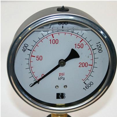
• Ability to purchase fire pumping equipment, accessories and valves directly from the importer and delivered to site.
• Unmatched lower prices
• Access to 24 hour technical assistance and support provided by qualified and QBSA licenced technicians
• UL, FM and AS approved equipment


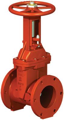
PRODUCT SHOWCASE
Fire Equipment Australia Proud Business Partners 24 Hour Hotline: (07) 3216 7373 | Direct office enquiries: (07) 3355 7676 Email: sales@fireequip.com.au | ABN 82 160 259 870 Suppliers of equipment you know and trust Huge savings on equipment you use everyday
Bruce Ellis
In the ongoing Pump Pioneer series, Chris Bland catches up with Bruce Ellis who started in the industry almost 50 years ago and whose career included many years as Managing Director of Mono Pumps
When did you first get into the pump industry?
I got into the pump industry by accident in June 1964. After completing my Degree in Mechanical Engineering at Uni of Melb and a 2 year Graduate Apprenticeship at GEC Steam Turbine Works in England, I was looking for a fill in job before starting Teacher Training in 1965. I went for a practice interview at Ingersoll-Rand (IR) in South Melbourne and accepted a job as a Sales Engineer specialising in pumps. At that stage I didn’t even know what a Sales Engineer did. I stayed with IR for a 15 years and never did get to Teachers College.
I got into pumps by accident. IngersollRand had recently started making pumps in Australia and were looking to increase sales of pumps in Australia. I was lucky that, at the time, there was a lot of expansion activity in the Refining and Petrochemical industries in Melb and Sydney and, with the backup from some good engineers in Ingersoll-Rand, was able to achieve good sales success.
After 15 years at IR, during which I moved from sales engineer, to sales manager, state branch manager, head office product manager and finally to manufacturing manager, I left IR and the pump industry to join Jaques Ltd as General Manager. This was an interesting two years in heavy engineering related to mining and quarrying, but I must have been subconsciously missing the pump industry because I was attracted to apply for a job as General Manager of Mono Pumps. After about 18 months at Mono, I was promoted to Managing Director.
I left Mono after 15 years and worked part time from home in a consulting/ sales role for a small USA maker of specialised Rock Drills that were used
primarily in drilling 200 to 1000mm foundation holes for bridges, landslide barriers, and buildings. This job involved frequent, enjoyable, trips to Japan.
I was then headhunted to start a small Australian Branch office for Roto Pumps who are an Indian competitor of Mono Pumps. This was an interesting, successful, learning experience that involved me more closely with Pump Distributors and the networking that is invaluable in small business.
My final (at least so far) involvement in pumps was 3 years as part-time pump technical specialist at Stevco Seals and Pumps.
What do you like about the pump industry?
I had always been interested in most things mechanical and always wanted to know how things worked. Pumps, along with other IR products such as process gas compressors, were not only intriguing themselves, but led to my involvement in various processes that used pumps, and other machinery that were used in those processes. In those days, it was easy to obtain permission to go on site to view existing processes and equipment in operation, and to get involved in troubleshooting that enhanced both my own and IR’s reputations.
To successfully sell pumps to Engineers and Engineering Contractors, you had to offer application advice that was valuable and dependable. In other words, the pump user had to consider that you were acting as a consultant first and salesman second. Your company also had to have good designs and be competitive. Fortunately, at my practice interview, i lucked out in picking IR.
Pumps are used in virtually every
industry and so give you the opportunity meet a very wide selection of people and be involved in a wide range of problems and successes. I have had the good fortune to spend hours yarning around campfires on NT Cattle Stations, after helping solve borehole pump problems. And have enjoyed problem solving with top Chemical Engineers in the Petroleum Industry, Chemists in Food Manufacturing, or Distributors of Solar Pumps.
How has the industry changed during your time in it?
I guess that the biggest change has been the reduction of import Tarrifs and changes to Exchange rate. As president of APMA in the late 1980s or early 1990s, I presented a pump industry view to the Industries Assistance Commission. The IAC recommendation to reduce pump Tariffs from 33% to 5%. The IAC’s view was that it would force manufacturers to become more competitive. The pump industry view was that it would force manufacturers to look at their options, with the most likely option being to import pumps rather than make them in Australia. This was especially likely considering the fact that most manufacturers were either overseas owned or had existing strong licence agreements or commercial relationships with overseas pump companies I think that history has shown that the pump industry view was more accurate. However, it is great to see that a few pump manufacturers such as TKL, United, Warman, and Mono have continued to make pumps locally.
What are some of the highlights of your career?
• I helped negotiate Ingersoll Rands largest Australian made pump order ($1,000,000 in 1967), and then supervised installation and commissioning.
PIONEERS 60
PUMP
• whilst I was managing manufacturing, in the mid 1970’s, IR made Boiler Feed pumps up to 3,000 HP, vertical cooling water pumps with 69 inch suction, and 1/2 HP water pumps.
• After retrenching 90 people in late 1970s with plenty of advance notice, it was pleasing that all except one employee had found alternative employment by the time he left IR
• I led Mono’s Engineering and Marketing team to develop a range of solar powered pumps for borehole and low capacity surface water pumps. This was an ongoing program that started in 1984 resulted in a world competitive range by the mid 1990’s.
• During a visit to Perth in the early 1990’s, I was able to sketch out a new range of pumps (during a lunch with a senior customer and Mono’s Distributor) that, following detailed engineering and development, met the customer requirements that we had identified. This new high pressure range greatly extended the previous range and became one of the fastest growing market segments of Mono’s worldwide industrial products. This range was primarily used for mine dewatering.
• Implementing a major upgrade of manufacturing and materials handling at Mono pumps in early 1990’s after many years of trying to gain capital Expenditure approval from the UK parent company. The upgrade included one of the latest CNC machines for manufacture of rotor blanks, shafts, etc and included innovations to use the machines more flexibly than in the UK.
Did you have a mentor at any time in the industry?
I had many mentors during my career. The one who I remember most clearly was Barry Ash, the engineer who spearheaded Ingersoll-Rands move into pump manufacture in the early 1960’s. As well as guiding me on pump capabilities, trouble shooting, and never say “can’t” approach to manufacturing, Barry once asked me a question that helped me balance work and private life forever. The question was: “Are you working to live, or living to work”? My interpretation of this was - If you do not work hard and smart, you will not be successful and family life will suffer. If you work too hard or too long hours, family life will suffer, and this will effect your work results.

Tell me about some of the other personalities in the industry that you have worked with?
Peter Moate. Peter was Branch Manager when I joined IR. Peter was not a pump man but taught me a lot about selling techniques and staff motivation. Peter went on to be Chairman of Eagle & Global Steel.
Bill Smith. Bill was the IR pump salesman in Sydney whilst I was selling pumps in Melbourne. We teamed together on numerous projects where the Engineering and Purchasing was done in Melbourne for a Sydney user, and vice versa. To be successful you had to work as a team and forget about who might get the most sales credit. Bill went on to buy a small pump company that he built into Kelair Pumps.
George Snow. George was the first employee of Mono Pumps in Australia. He developed and grew the company into the leading positive displacement pump manufacturer and supplier in Australia, and, I believe, was a founding member of Australian Pump Manufacturer’s Association (APMA). George became Chairman of Mono Pumps (Aust) when I became MD. Are you still involved in the industry today?
I have fully retired but have enjoyed a part time return to lead the re-write of the Positive Displacement Pump section of PIA Technical Handbook in conjunction with Alan Rowan and Geoff Daniels. This short project is virtually complete.
What advice would you give young people in the pump industry?
In any new job, you need to work particularly hard in the first 6 months to learn your job and to make your mark. Then,
and only then, look at the life balance between work and family (refer to 7 above). If you don’t get this right, you will not be successful in the long run. Because life continually changes, look at your life balance at least every couple of years.
If you are a pump salesman, I think that my strategy is still relevant. The first order is the tough one. Once you get it, stay with it and make sure it is successful. Use the application to learn about the customer’s industry and problems - it is much easier to get site access and your customer’s ear after you have the order than before. Make every sale and every field problem a learning experience. Then use this experience to help future customers to either avoid the problems, or if problems occur, use the opportunity to show that you and your company can solve problems faster than your competitors.
What do you like to do in your spare time?
I guess that I am a bit of a sporting and fitness fanatic. In summer I race small sailing dinghies three or four times per month and in winter, I cross-country ski as often as possible and race at least twice per season. This program gives me the year round incentive to stay fit with gym work, roller ski training, and swimming. These are supplemented by Tai Chi (I am an assistant instructor three hours per week), and Yoga.
My wife and I enjoy reading, weekends away at our on site van at Waranga Boat Club, a major overseas trip each year, and frequent MG Car Club activities with our two MG’s (1949 MG TC, and 2005 MG F).
I don’t know how I found time to work!
61
PUMP PIONEERS
The Mono team, from left to right; Bruce Ellis, Jacy Roach, Jim Mitchell, Simon Lambert and John Farrell.
Saving pump energy using air valves
By Johan Cilliers, Valve Product Manager, Amiad Australia
In our environmentally sensitive world, the need for air release from liquid transfer systems to improve system efficiency is gaining momentum.
The National Energy Savings Initiative recently published a report based on an analysis by ClimateWorks Australia which estimates that about $3.2 billion can be saved annually on energy costs by reducing baseline energy consumption by only 11%. A major part of the national energy consumption goes into operating drinking water and wastewater utilities, where every volume of water passed through a system, represents a significant energy cost and is
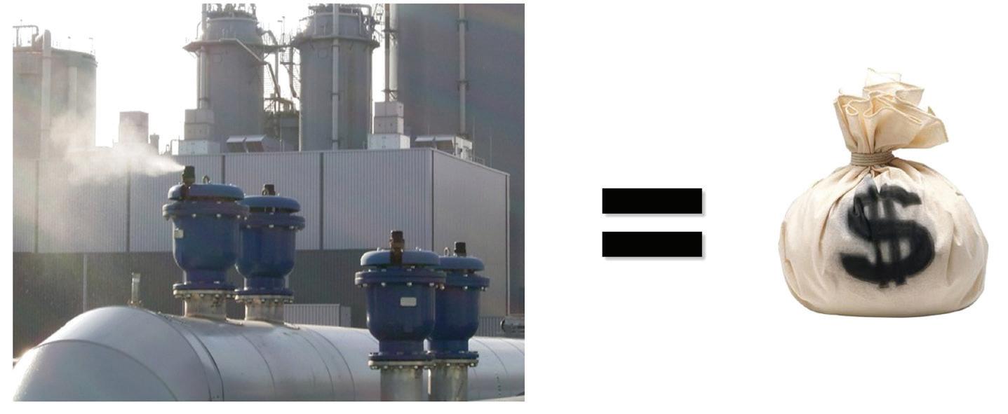
often the second to third largest expense that a water utility must cover.
Although the potential for considerable energy conservation by using air valves was claimed many years ago, only limited research has been conducted on this matter to date.
Air valves are sometimes labeled a form of black art, but once the basic air valve types and their primary functions are understood, it is surprisingly simple.
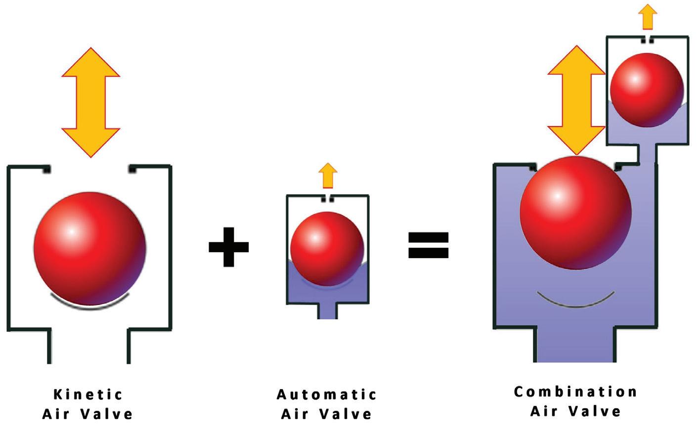
A “kinetic” or “large orifice” air valve has a single, large orifice with a single large float as its only moving part, and has two primary functions:
To allow the discharge of relatively large volumes of air from the pipeline during pipe filling and then closing as water enters the valve, followed by its equally important “vacuum breaking” function to introduce air back into the pipeline during pipe draining or in the event of pipe surges.
The “kinetic” or “large orifice” air valve component has one limitation in that it cannot release any air once it has closed when the system has been primed and pressurized, due to the (upwards) hydraulic force applied to the area of the relatively large orifice [Fh=P x A], which is significantly greater than the (downwards) gravity force of the float [Fg =m x g]. This means that the float remains in its closed position, regardless of whether the valve accumulates entrained air once the pipeline is in pressurized system operation.
An “automatic” or “small orifice” air valve has a single small orifice to “automatically” release smaller volumes of air, where
62
TECHNICAL

Even during Roman times the need to purge air from primitive water transfer systems was acknowledged, as illustrated by these ancient “air valves” made from hollowed-out rocks.
the orifice is small enough to create a hydraulic force less than the weight of the float, allowing it to open when entrained air accumulates inside the body even while the system is primed and pressurized.
When we combine one large “kinetic” and one small “automatic” orifice component into one unit, the resulting “Combination” or “double orifice” air valve can then perform both the small and large orifice functions. The resulting combination air valve is the most commonly used
air valve type in operation across the world. (Note: the term “double acting” is often used to indicate double orifice, but is ambiguous and not recommended).
Over the years several other features and functions have been developed and added to different air valve models and options available today include special “air gap separated” air valves, designed to handle liquids containing solids such as wastewater or other environmentally sensitive fluids such as in hyper-saline dewatering applications. Other sub-types
or add-on options include one-way bias devices to allow air in- or air outflow only, or non-slam / slow release air options to reduce local closing slam associated with (too) high air discharge velocities by restricting the air discharge rates with a third orifice of intermediate size. Most of the anti-slam air valve types can also be applied for system surge mitigation, effectively slowing down the water velocity in the system when & where appropriate, while the latest and more advanced “dynamic” air valve type operates on a different technology to most other combination air valve types, allowing high air discharge rates, but avoiding air valve closing slam by closing slowly.
Regardless of all these types and options, the “Combined” kinetic and automatic functions remain the primary purpose for the majority of air valves installed on pipelines.
There are several common sources of entrained air in liquids (some more common than others), but in virtually every pipe system entrained air is released from solution and increases in volume as the system pressure decreases. As the pressure decreases along the pipeline, every dis-entrained air bubble expands (ideal gas law : [PV =
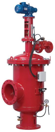

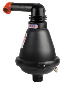
TECHNICAL
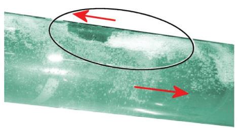
nRT]), to displace a larger volume of water resulting in increasing its buoyancy force [Fb= ρ x V x g], driving the larger bubbles towards the crown or high points along the pipeline. Air bubbles also flow along the crown of the pipe and can merge with similar bubbles into even larger pockets of air.
This natural tendency of air bubbles to rise vertically upwards, also causes air bubbles to rise against flow direction on downhill sloping pipe sections. At a “critical” flow velocity, the smaller air bubbles start to be dragged along the flow, but although a few attempts have been made by researchers to predict the critical flow velocity, most resulted in different results and formulas for various pipe diameters and pipe slopes.
One reason for the different results from the various “critical” flow velocity research projects, is that although smaller air bubbles may start to get drawn in the flow direction on a downhill
sloping pipe above certain flow velocities, some of these smaller bubbles then merge into larger pockets which then again rises against the flow direction due to the increased buoyancy force of the larger pocket, and again accumulate at local peaks along the pipeline.
Recent research projects indicated that the headloss at the location of each air pocket is typically equal to the vertical height (“H”) of such air pocket.
With many such air pockets potentially trapped along a pipeline and almost certainly at any local peaks relative to the HGL (Hydraulic Grade Line), each such air pocket restricts the liquid flow passage, increasing the flow velocity and associated friction loss below the air pocket for the “length” of the air pocket, somewhat like a semi-closed valve at each such location.
The red HGL on this illustration assumes only one such trapped air pocket, and indicates the additional losses the pump needs to overcome due to the trapped air, compared to the designed (ideal) HGL in blue, which assumes no air pockets.
Centrifugal pumps come in many different models, types and sizes, with different characteristic pump curves, some with relatively flat curves, and others steeper.


Some of these curves are stable and some are unstable (as explained in previous pump magazine articles), with potentially more than one possible operating duty.
Submersible centrifugal pumps typically have relatively low operating efficiencies, while end-suction centrifugal pumps with suction pipe connections are often more efficient.
There are several reasons to select a pump to operate at best efficiency point (BEP), not only to limit pump wear, but also to deliver the highest flow rate at the lowest power requirement.
Every system has different hydraulic characteristics and similarly every pump has a particular characteristic pump curve. But let’s consider the additional pump pressure required in the HGL comparison above. From the pump and system curve point of view, we see that the pump duty point moves back up the pump curve when air is trapped in the pipe, not only resulting in increased pump duty pressure and reduced flow rate delivered, but the pump efficiency has also decreased.

The pump shaft power requirement can be calculated, where the power required in the illustration above increases by a considerable 6.5%.
In the example above the pump curve is stable and relatively flat, and assumes only a single trapped air pocket, hence

in many cases the increase in pumping power can vary considerably, as illustrated by the following case study.
Case Study
The following pump records are for a wastewater system which was performing well below its designed capacity. The system was investigated and since these symptoms are consistent with flow restrictions such as trapped air, the decision was made to replace some of the existing kinetic only air valves with combination type air valves, to enable automatic (small orifice) release of the entrained air while the system was operating.
64 TECHNICAL
Pump and system curves with and without air trapped
HGL with and without air trapped
Downslope entrained air flow

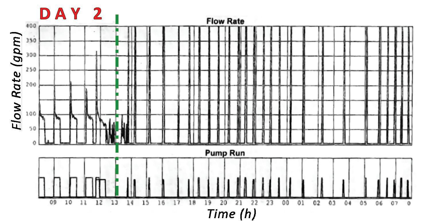
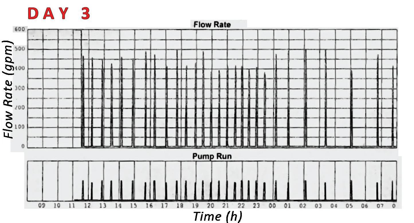
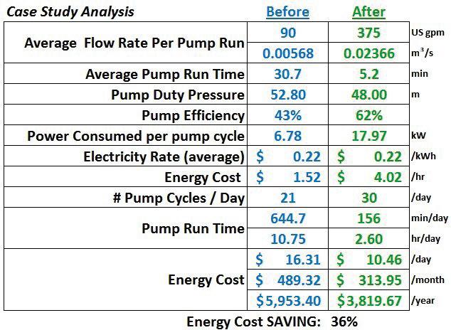
The first 24 hour pump operation record (BEFORE) is of the system while originally fitted with five kinetic (large orifice only) air valves along the pumping main, showing relatively long pumping periods, and low flow rates.
During the second 24 hour operation record, two of the kinetic (only) air valve types were replaced with A.R.I. D025 air gap separated combination air valve types. An immediate system improvement not only caused the pump operating periods to decrease, but also resulted in the flow rate improving such that the flow rate reading literally went off the report scale.
On the third 24 hour operation record (AFTER), the report’s flow rate scale was re-adjusted to show the full extent of the new, efficient system operation.
The payback period for the two A.R.I. air gap separated combination air valves valued at around $1150.00 each is approximately 13 months, but this payback period could even be less considering that the pump life is also extended in terms of bearing and seal life, or cavitation free operation when operating near the pumps’ best efficiency point.
The Author
Johan Cilliers majored in fluid mechanics during his mechanical engineering studies before 15 years of pump station- and associated hydraulic design consulting work and 5 years of pump contracting- and automatic control valve design work in South Africa. Johan was appointed to the position of senior air and automatic control valve applications engineer and national valve product manager for Amiad Water Systems (Australia) in 2002, and regularly presents air and automatic control valve application training to various water authorities, consulting engineers, major contractors and other water industry stakeholders across Australia.
Acknowledgements
Contributions from and peer reviewed by Bernd Husemann, director of Airvalve Germany, Laurent Dupuis, product manager of Airvalve France, Yiftach Brunner, applications engineer of A.R.I. Flow Control Accessories ltd, and Jamie Pickford, WA state manager of Amiad Water Systems.
65
TECHNICAL
Understanding pump curves 3: centrifugal pumps in parallel
By Ron Astall, United Pumps Australia
Centrifugal pumps are frequently operated in parallel to achieve higher system flows, to enhance system flexibility or to provide greater pump redundancy and hence better system availability. For very large projects, limited availability of sufficiently large pumps or limits on driver size or electrical starting current may dictate the use of multiple pumps. There are traps for the unwary. Simply running an additional pump in parallel may not provide the expected results.
In our last article Stable & Unstable Curves, we looked at what makes a centrifugal pump curve “stable or “unstable”. We also discussed the importance of understanding your system and, in particular, how the system will only operate where the pump curve intersects the system curve, and the differences between “steep” system curves and “flat” system curves. These preceding concepts are absolutely crucial to understanding many of the issues associated with operating pumps in parallel.
To begin, we will define parallel operation and outline how to predict system performance when two or more pumps are operated in parallel. We will discuss
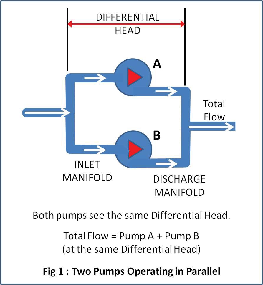
selection rules for parallel operation and then look at how different system characteristics react to parallel pump operation.
Parallel operation
“Parallel” operation means that two or more pumps are operating with common inlet and outlet systems. This means that each pump will have the same differential head. The total flow is the sum of the individual pump flows. See Fig 1.
Predicting performance
To predict the system performance, a combined curve for all pumps can be produced by adding the individual flows from each pump curve at a common head. This is illustrated in Fig 2 below :
As with any pumping system, the system will operate where the combined curve intersects the system curve.
In this example, the Pump curves used are not identical and this highlights a likely serious operating problem. Because Pump ‘A’ has a higher head at zero flow, this pump will overpower Pump ‘B’ at low system flows. This is highlighted in Fig 3.
In this scenario, the pump with the lower head will be stalled, and assuming that a non return valve has been fitted, it will be running at closed valve with all the attendant risks and damage.
Matching pump curves for parallel operation – selection rules
The primary concern when running centrifugal pumps together in parallel is that pumps share the load safely at lower flows.
This does not mean that pumps must have identical characteristics. Groups of low flow pumps and high flow pumps are often operated together in parallel to match variable system demand. The aim is that all pumps have matching heads at low flow to prevent pumps being stalled or blocked in by the others.
1. It is most important that the zero flow or “shut valve” heads are matched for pumps that will operate together in parallel.
2. Unstable pump curves must be avoided for parallel operation, particularly where there is any chance of operation anywhere near their point of instability. Unstable pump curves present a very real risk of surging when operating in parallel.
3. Steeper pump curves are preferred for parallel operation to assist with load sharing at low flows. Pump curves that are very flat at low flow are prone to wide flow variations with
66
TECHNICAL

minor changes in head and may make load sharing difficult. See Fig 4.
4. Be aware of minor performance variations that may change the suitability of otherwise well matched pumps. If one pump has had more use and is worn, its curve may no longer match the other pumps. Pumps using different drivers such as a steam turbine driven pump operating in parallel with an electric motor driven unit may operate at sufficiently different speeds to cause mismatch of pump curves at low flow.
Will parallel operation suit your system?
This depends on what you are trying to achieve.
If the aim is to increase and decrease system flow by operating one, two or more pumps in parallel to meet changing demand then it is important to understand the type and limitations of your system.
If your system curve is relatively “flat”; ie. mostly static difference in levels and minimal pipe friction, then operating pumps in parallel will provide a useful performance variation.
If your system is mostly friction resistance (a steep system curve) such as a closed loop circuit or a lengthy pipeline, then performance variation will be minimal. This may be a good or a bad thing depending on what you are trying to achieve.
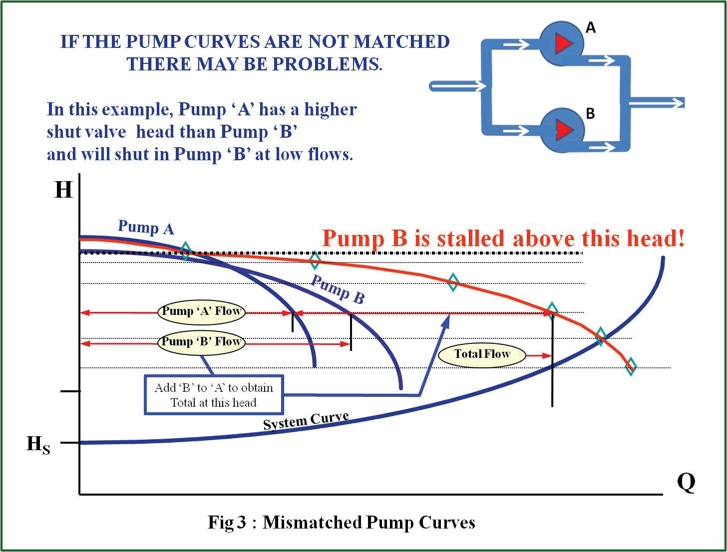


67
TECHNICAL
Flat system curves
Refer Fig 5.
When the system resistance is relatively flat (not much friction), operating additional pumps in parallel will produce a useful flow increase. Incorrectly, many operators expect that flow will double if two pumps are running in parallel. This cannot happen because, when added together, the combined pump curve intersects the system curve at a higher head due to increased frictional resistance and hence each pump will be operating at a higher head and lower individual flow than when operating alone.
Steep system curves
Refer Fig 6.
When the system curve is steep (mostly friction) this steep increase in friction head as system flow increases, means that each pump will be running at a significantly higher head and the individual pump flows will be much less than in single operation. Overall, the change in flow will be small when additional pumps are switched on.
This may be frustrating if you want to increase or vary system flow by switching pumps on and off.
Conversely, this particular aspect of steep systems; such as long pipelines and closed loop recirculating systems; is very useful to pump users that need to maximise system reliability.
These users will often specify multiple combinations of pumps operating in parallel to minimise system disruption in the event of a pump failure.
Typically, in critical applications such as cooling water circuits, three pumps may be installed with the normal operating mode being two running in parallel and the third being a standby unit. If it becomes necessary to shut one of the operating pumps down, the remaining operating pump will still provide a high percentage of the system flow until the standby pump can be started.
Is parallel operation good for you?
Installing pumps to operate in parallel can be an excellent strategy.
It is however very important to understand the aim of the exercise.
Parallel pump installations are a great idea in the following circumstances:

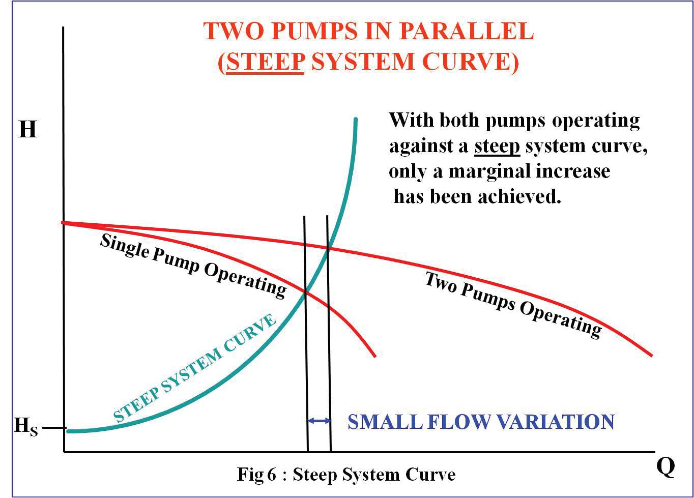
1. Where limited availability of sufficiently large pumps or limits on driver size or electrical starting current dictate the use of multiple pumps.
2. When flow needs to be varied according to varying system demand and when the system resistance characteristic is reasonably “flat”.
3. Where the use of multiple combinations of pumps operating in parallel in a “steep” system resistance will minimise potential system disruption in the event of a pump failure.
Remember:
1. It is most important that the zero flow or “shut valve” heads are matched for pumps that are to operate together in parallel.
2. Unstable pump curves must be avoided for parallel operation.
3. Steeper pump curves are preferred for parallel operation.
4. Be aware of minor performance variations that may change the suitability of otherwise well matched pumps.
Most important of all; understand your system.

68
TECHNICAL Next issue : Is variable speed the perfect solution?
pump school

Glossary of pump terms A-K
Brown Brothers Engineers Australia Pty Ltd, www.brownbros.com.au.
A
Absorbed Power
The actual amount of power being consumed by the pump at a specific flow and head.
Adapter (or Support Head)
Connects and aligns the power (bearing) end of an ANSI pump to the wet end.
A.N.S.I. B73.1 Standard
American National Standards Institute. A set of specifications (envelope dimensions) for centrifugal pumps.
Absolute pressure (normally in kPaA) Atmospheric pressure added to gauge pressure.
Affinity laws
They are used to determine changes in capacity, head and power due to changes in shaft speed. The same laws can be used to estimate changes in capacity, head and power due to changes in impeller diameter.
Air ingestion
Air is coming into the stuffing box because of a negative suction pressure.
Alignment
The centreline of the pump is perfectly aligned with the centreline of the driver (usually an electric motor).
Ambient temperature or pressure
The environmental temperature or pressure in the area where the equipment is located.
Atmospheric pressure
At sea level, atmospheric pressure 101.3 kPaA.
API Standards
Standards produced by the American Petroleum Institute for various pieces of equipment applied in the oil and gas industries. Various API codes are applicable for pumps dependent on the type of pump. Examples are API610, API685 etc.
Axial Thrust
The resultant of all axial forces (i.e. in direction of the pump shaft) acting in the pump rotor.
Axial Thrust Balancing
Methods by which the axial thrust is balanced to minimize bearing loads.
B
Back to Back Impellers
In multistage pumps, some impellers are located on the shaft facing opposite directions. This is one method of achieving axial thrust balancing.
Back plate
Used in some centrifugal pumps to position the stuffing box and provide an impeller wear surface.
Back Vane
A radial narrow vane located on the back shroud of an impeller and is designed to balance axial thrust.
Back pull out pump
A design that allows the wet end of the pump to be left on the piping yet allows the power end and adapter to be removed. A.N.S.I. pumps are designed this way.
Back to back double seal
Two mechanical seals located in a pump with the rotating seal faces in opposite directions.
Balance Holes
Holes in the back shroud of an impeller designed to balance axial thrust.
Balanced seal
A design in which the seal face closing area is reduced to lower the closing force, and reduce the heat generation between the faces.
Ball bearing
Consists of an inner race, an outer race, and a series of balls between them. Often called a precision or anti friction bearing.
Bar
Metric unit for pressure and is equal to 100 kPa.
Barrier fluid
The high-pressure fluid that is circulated between the two seals in a double mechanical seal. The fluid should enter the bottom and leave the top to prevent air pockets.
Base plate
The pump and motor are mounted on this unit.
Bearing
Supports the rotating shaft and allows it to turn with a minimum amount of friction. Could be either sleeve or antifriction type.
Bellows
A component of a mechanical seal that can be manufactured from metal or nonmetallic materials to eliminate flexing, rolling or sliding.
Belt Drive
A combination of belts and pulleys that transfers torque from the driver to the pump.
B.E.P (Best Efficiency Point)
The best efficiency point on a pump curve for a specific impeller diameter. It is the point where the power coming out of the pump (water power) is the closest to the power used by the pump (absorbed power) from the driver. This is also the point where there is no radial deflection of the shaft cause by unequal hydraulic forces acting on the impeller.
Buffer fluid
The low pressure fluid that is circulated between the two mechanical seal in a tandem seal.
Buna N
Sometimes called Nitrite. A common elastomer used in the sealing of oil or water.
69
Bushing
A close fitting support device used to restrict flow between two liquids, thermally isolate a hot liquid, support the rotating shaft or break down pressure.
Bypass line
material e.g. liquid to vapour, liquid to solid, solid to vapour.
Close-coupled
This is a German standard that defines various industrial products.
Deflection Movement or displacement of the shaft in a radial direction.
Density

Used to either re-circulate fluid from the pump discharge to the stuffing box, the stuffing box to the pump suction, or the pump discharge to a lower pressure point in the system. This can also be used as a manual means of flow control.
C
Canned pump
A seal/less pump with the shaft, bearings and rotor contained in a can to prevent product leakage. These are generally limited to pumping clean lubricating liquids.
Capacity
Volumetric flow of liquid measured in, litres/sec, m3/hr etc.
Cartridge seal
A self-contained assembly containing the seal, gland, sleeve, and both stationary and rotating seal faces. Usually needs no installation measurement. Must be used in a pump with impeller clearance adjustments are made.
Cavitation
Cavities or bubbles form in the fluid lowpressure area and collapse in a higherpressure area of the pump, causing noise, damage and a loss of capacity.
Centreline design
The pump is mounted to the base plate by feet attached to the sides of the volute instead of the bottom. These are used in higher temperature pumping applications e.g. API applications and allows thermal expansion to occur in without the necessity of re alignment.
Centipoise
One unit for dynamic viscosity of a liquid.
Centistoke
One unit for the kinematic viscosity of a liquid. Dynamic viscosity divided by the liquid specific gravity at the same temperature gives kinematic viscosity.
Centrifugal pump
A pump that imparts energy to a liquid with centrifugal force.
Centrifugal separator (or cyclone separator)
Equipment that utilises centrifugal force to separate solids out of the fluid. In pumping, they are used in seal flush lines.
Change of state
This defines a change in phase for any
A close-coupled pump is characterised by a common or rigidly-coupled motor and pump shaft. These pumps do not have a flexible coupling. There are no pump bearings and all thrust is carried by the motor bearings.
Concentricity
When the parts share the same centerline they are concentric to each other.
Condensate
This defines the change on phase of a vapour to liquid e.g. steam to water.
Constant Level Oiler
This is used to maintain the oil level in a bearing housing to the correct level as oil is used.
Cooling jacket
Cooling jackets can be located on the pump casings and /or the stuffing box of the pump to control the temperature of the fluid. Cooling jackets can be part of the component casting or separate bolt on items.
Corrosion
This is a chemical or electrochemical reaction on material surfaces that changes the profile and/or composition of the surface.
Corrosion resistant
An arbitrary term that indicates a corrosion rate of less than 0.05 mm per year.
Coupling
This is used to connect the pump to the driver. It transmits torque between the driver and pump. It can be a flexible coupling that allows some axial and radial misalignment or rigid which does not allow for any misalignment. Allowable misalignment is determined by manufacturers of the coupling.
Critical speed
Any object made of an elastic material has a natural period of vibration. When a pump rotor or shaft rotates at any speed corresponding to its natural frequency, minor unbalances will be magnified. These speeds are called the critical speeds.
Cryogenic Pumping
This generally refers to pumping liquid gases at very cold temperatures.
Cutwater
A part of the pump casing that directs the pumped liquid to the pump discharge. D D.I.N. standard
Measured in kg/m3 or lb/in 2. This is the ratio of the mass of a liquid in a given volume to the magnitude of that volume. Refer to Specific Gravity.
Design Duty Point
This is generally defined for a pump as a capacity at a head or pressure of the liquid being pumped, ideally the design duty point on a centrifugal pump as at BEP.
Dilatant liquid
A liquid whose viscosity increases with increased shear rate e.g. agitation.
Differential Pressure
The difference between the outlet pressure and the inlet pressure. Differential pressure is sometimes called the Pump Total Differential Pressure.
Discharge Head
The outlet pressure of the pump converted to head of liquid.
Double seal
An outdated term describing two seals in a pump. The latest terminology is “dual seals”, back-to-back double seals or tandem seal. In the past the term was used to describe a higher-pressure barrier fluid between dual seals.
Double suction pump
A pump with an impeller where liquid enters the impeller on both sides. The rotor is generally (but not always) suspended between two bearings. These pumps are generally of higher capacities.
Double volute
A centrifugal pump design that incorporates two cut waters to decrease radial loads and minimise shaft deflection when the pump is operating away from the B.E.P. Lowers the efficiency of the pump and therefore seldom used on smaller size impellers.
Dry running
Operating a pump without liquid in the pump and therefore in the seal area.
Dual Seal
Two seals running in various configurations back to back, tandem, face to face, or concentric.
Ductility
The property of a metal that allows a great deal of mechanical deformation without cracking.

70

Efficiency
In centrifugal pumps, this is the useful power in the liquid to the expended power. That is power out of the pump divided by power into the pump.
Elastomer
A rubber-like material that, when compressed and then released will basically return to its original shape in less than five seconds.

Electrolysis
A process involving chemical change caused by the passage of an electric current through a liquid.
E.P.D.M or E.P.R
Ethylene propylene rubber. This is a common elastomer used in the sealing of water based and higher pH materials. Cannot be used in petroleum products.
Erosion
This is wear caused by mechanical action of the liquid on the surface of the materials. It is obviously more prevalent if the liquid contains solids.
Eye of the impeller
The center of the impeller where the fluid enters.
F
Face combination
The materials chosen for the two lapped seal faces. An example is carbon graphite running on silicon carbide.
Face-to-face seals
Two seals running against a common seal face. The barrier fluid pressure is always lower than stuffing box pressure.
Face lubrication
The fluid or vapor that exists between lapped mechanical seal faces.
Face pressure
The sum of all the loads on the seal face including the spring load, hydraulic load and shaft axial thrust, divided by the area of the seal face. This face load is reduced by friction between the sliding elastomer and the shaft or sleeve.
Flashing
A rapid change in phase from a liquid to a gas.
Flooded suction
This refers to a situation where the liquid level on the suction side of a pump is higher than the pump centerline and the liquid flows to the pump by gravity.
Fluorocarbon
This is a genetic term for an elastomer of which Viton (a Dupont product) is a typical example. The material has good
compatibility with hydrocarbons, has high temperature capability but poor mechanical life.
Flush
Putting an outside liquid into the stuffing box of the pump at a pressure higher than stuffing box pressure. All of this liquid mixes with and dilutes the pumped fluid.
Foot Valve
A type of check valve with a built-in strainer. Used at the point of the liquid intake to retain liquid in the system, preventing the loss of prime when the liquid level is below the pump centreline.
Free length
The uncompressed axial length of a seal.
Friction Head
This is the head loss due to friction as liquid flows in pipes and fittings.
G
Gasket
This is used between two static surfaces to provide a seal. Made from a variety of deformable materials.
Gland
The part that holds one half of the mechanical seal and attaches to the stuffing box.
H
Hard face
A seal face either rotating or stationary. The most common materials are silicone carbide, ceramic, tungsten carbide, Stellite, Ni-resist. The hard face must be the wider seal face.
Hastelloy “C” (also known as Alloy C)
A nickel-rich, corrosion-resistant and very hard alloy.
Head
The equivalent height of the liquid that will produce a particular pressure. Can be calculated from H (metres)= pressure in kPa/(9.8 x specific gravity).
Horizontally Split Pump
This is a pump where the casing is split into two sections in the axial plane. This means there is a top and bottom-half casing. Connections are normally on the bottom-half casing to allow removal of the top casing for pump inspection without needing to disconnect pipework.
Hydraulic balance
A method of reducing mechanical seal face loading by reducing the seal face closing area.
Hydrocarbon
A petroleum product consisting of hydrogen and carbon.
II.D.
Inside diameter.
I.S.O.
International Standards Organization. Sets pump and seal standards for the metric community.
Impeller
The rotating component of a centrifugal pump that imparts energy to the fluid being pumped. Available in open, semiopen and closed design.
Impeller eye
The centre of the impeller or the point where fluid enters the impeller.
Impeller shroud
The plates located on one or both sides of the impeller vanes. Prevents solids from penetrating behind the vanes.
Impeller vane
Located between the eye and the discharge side of the impeller. Directs the flow of the liquid to the outside diameter of the impeller.
Inducer
A small axial flow vane that attaches to the impeller of a centrifugal pump that reduces the N.P.S.H. required by a pump. This improvement occurs across a narrow capacity range and the impact can be detrimental outside of this range.
Induction motor
The most common type used in industry. Has a slippage of 2 to 5 percent compared to synchronous motors.
Inline pump
Mounted in the piping generally between two flanges. No base plate or alignment required.
J Jacket
Usually refers to the heating/cooling jacket surrounding the stuffing box on some pumps.
K Kalrez®
An “elastomer-like” material manufactured by E.I. Dupont that is used to seal most solvents and other aggressive fluids. It is available in several different grades.
Kilowatt
One thousand watts. The normal unit for power in the metric system.
Kpa (kilopascals)
A metric unit of pressure.
71
E
L-Z will appear in the next edition
Editorial schedule
August 2013
Main feature
Pump manufacturing
Imports & exports
Industry Focus
November 2013
Main feature
Focus
February 2014
Main feature
of the industry
Focus
& heavy industry
Pump Products
protection
May 2014
Main feature
Reliability
Industry Focus
Water
HVAC
Plastics, rubber, chemicals
Pump Products
Seal-less pumps
Deadline: 14 June, 2013 Related Products:
and drives
Cylinders & actuators
Pump Products
Deadline: 6 September, 2013
Instrumentation, control & monitoring
Pressure, temperature and level gauges and sensors
Vibration instrumentation and analysis sensors
Flow meters, control panels
alignment tools
Condition monitoring sensors
Deadline: 29 November, 2013
Related Products
Valves
Pipes and piping systems
Filtration systems
Lubricant & lubrication systems
Coatings
Custom casting
Vacuum pumps
Deadline: 21 March, 2014
Related Products: Seals
Connectors
Couplings & seals
Bearings
Mechanical seals/support systems
Elastomeric seals/gaskets/packing
Wear rings
f.el.som Middle East
Fire Equipment Australia Flowserve
Hydro Australia
Milton Roy
Northern Diesel & Hydraulic
Precision Balancing
ProMinent
Pump Affinity
Pump Systems
Pumps & Compressors Conf.
Pumpserv
Regal Beloit
Robertson Technology
Sterling Pumps
Stevco Seals & Pumps Victoria
International Corporation
Pumps
Missed out this time?
Don’t worry, as the next edition is just around the corner
Contact Chris Bland to book in now for the next edition to ensure you don’t miss out again; (03) 9440 5721 or magazine@pumpindustry.com.au Never
INDEX 72 ABB Australia Acromet Aesseal Amiad Australia Brown
Engineers Chesterton
Brothers
Crusader Hose Emtivac
Haskel
United
Australia Welling &
Xylem
Systems ADVERTISERS’ INDEX 45 3 23 63 6 OBC 47 17 21 59 10 9 29 9 34 33 51 49 19 IFC 37 13 31 25 7 IBC 8 11 15
Toshiba
Crossley
Water
State
Industry
Oil
Gas LNG Manufacturing
&
Pump
Mining Food Wastewater Coal Seam Gas
Motors
Gears
Compressors Fans
Balancing
Energy efficiency Industry
Power generation Fire protection Irrigation Pump
Repair & maintenance
Products
miss an issue - subscribe now for free
www.pumpindustry.com.au and hit subscribe to ensure you keep receiving Australia’s number 1 pump source!
Go to


 Figure 2
Figure 4
Figure 3


