
Secure IBC storage & decanting solutions
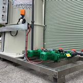
Polymaster’s unique Enclosed IBC Bund solves many of the problems associated with IBC storage and chemical/fluid decanting in a weather resistant, purpose-built enclosure.
Æ Full weather protection – stops rain entering the enclosure
Æ Easy forklift loading with wide forklift access from both side and back
Æ 250ltr day tank
Æ Lockable cabinet to keep system secure
Æ Venting by two sides
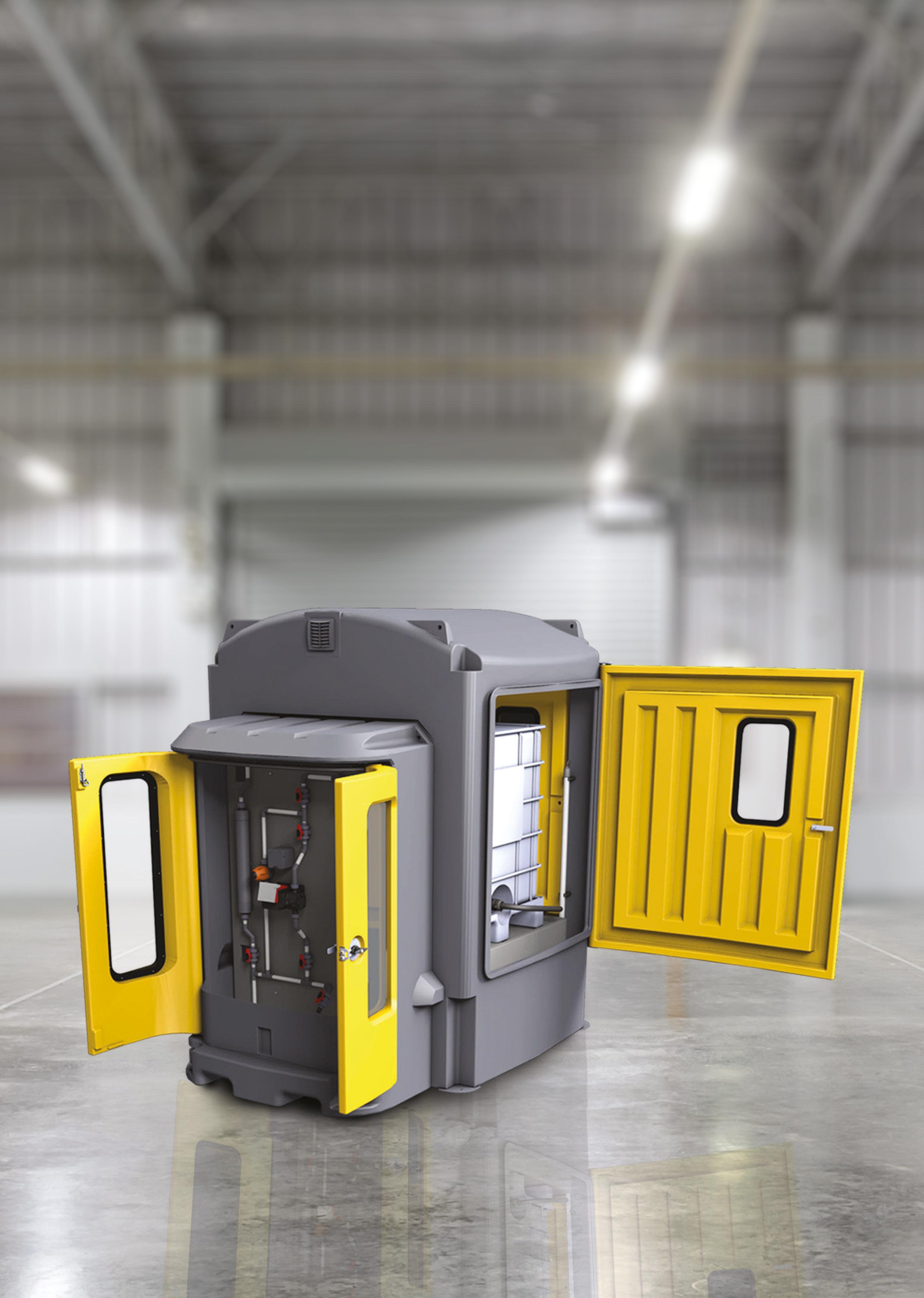
Æ Viewing windows incorporated into the doors
Æ 110% bund capacity complies with AS3780
Æ Sight tube and low-level alarm available
Æ Chemical resistant – high grade polyethylene construction


Hello all and welcome to the Spring 2023 edition of Pump Industry Magazine. By the time you read this edition it will be spring, always a welcome time; that said I feel we had a mild winter this year, or so it seems from here in Brisbane. As we head towards summer the Bureau of Meteorology is yet to formally announce whether we are entering another El Nino period, which would bring higher temperatures, dryer conditions and the likelihood of bushfires; the events in the northern hemisphere being a timely reminder of the devastation of such weather patterns.
• That there are health and safety concerns which can result from persons performing plumbing work without having completed a plumbing apprenticeship.”
Not the response we were hoping for, but not unexpected.
Pump Industry Australia Incorporated C/-340, Stuarts Point Road Yarrahapinni NSW 2441 Australia Ph/Fax: (02) 6569 0160 pumpsaustralia@bigpond.com www.pumps.org.au
PIA Executive Council 2023
John Inkster – President Brown Brothers Engineers
James Blannin – Vice President De.mem – Stevco
Kevin Wilson – Treasury/Secretary Executive Officer
Alan Rowan – Councillor Executive Officer – Publications and Training, Life Member
Ken Kugler Executive Officer – Standards, Life Member
Steve Bosnar – Councillor Franklin Electric/Pioneer Pumps
Geoff Harvey – Councillor Irrigation Australia
Joel Neideck – Councillor TDA Pumps
Jamie Oliver – Councillor Grundfos Pumps
Mat Arnett – Councillor Ebara Pumps
Michael Wooley – Councillor Tsurumi Pumps
Billie Tan – Councillor Regent Pumps
In the Winter 2023 edition I suggested that the RBA might increase the cash rate, however for the last two months they have chosen not to. But, there is consensus that there might be one or two increases yet to come as the RBA considers higher rates to control inflation, which has dropped to six per cent year-over-year down from seven per cent in the previous period. As we experience a softening in key parts of the economy, Australia is well positioned to weather tougher economic times not seen in other economies around the world, New Zealand included.
As I have stated previously, we are fortunate that the pump industry is a diverse one that provides a high degree of resilience not experienced by other sectors, which means that our industry remains in pretty good shape even if the economy is subdued over the coming months and maybe into next year. Agriculture, mining, trucking and rail are testament to that.
In recent editorials I have commented on the continuing dialogue with QBCC and the Services Trade Council (STC) regarding the rules, interpretation and regulations covered by the PD Act 2018. On 12 June 2023 the PIA Council received the following response from the STC.
“The Council have noted the concerns raised by your association and considered proposals for possible legislative amendments, including the introduction of a new restricted licence – the Council has decided to maintain the status quo.
The Council’s reasons for this decision were:
• That there are concerns with identifying and prescribing appropriate qualifications for a restricted licence, as specialist training programs do not currently exist; and
On 11 August a sub committee of the PIA held a meeting with representatives of the QBCC, where we asked for further clarification for the STC’s decision that states their concerns with identifying appropriate qualifications for a restricted licence. The PIA sub committee is investigating options to counter this argument. As the PD Act 2018 has legal implications for your business and many other SME’s I urge you all to review the Act to fully understand the potential ramifications to your business. The Act may be viewed by googling Plumbing and Drainage Act 2018
Of note is the Schedule 1 Dictionary of terms used and what “apparatus”, “drainage” and “plumbing” are defined as within the Act.
The meeting was cordial, constructive and informative, but it did occur to the sub committee that not enough is known about the Act and a lot more educational material is needed to help members understand what they can and cannot do. There is much to learn and know.
By the time this is published, a Breakfast Meeting will have been held on Monday 25 September, hosted by life member and stalwart of the industry, John Link of Link Pumps in Altona, who'll be sharing his 65 years of involvement in the pump industry. For those unable to make it, this meeting will be covered in the Summer 2024 edition of Pump Industry
And then on Tuesday 14 November the 20th AGM of Pump Industry Australia will be held at Box Hill Golf Club, Melbourne so please mark this in your diaries also. More information will be sent out closer to the event. The AGM is your opportunity to be involved and have your say about PIA activities and what you expect of Council; you may even consider election to Council, as there is nothing like being involved to augment change. It also marks my last term as President. After being President for four years and Vice President for ten years prior it is time for generational change.
Alan our Publications and Training EO is working on updating the PVC tables in the PFH and is working on an article on Intake Design for publication in Pump Industry Magazine.
Thank you for your continued support of PIA and hopefully will see you at our AGM.
John Inkster – President
Climate
population growth, and water scarcity are creating new challenges, and desalination is becoming an important alternative to traditional freshwater resources.



ABN: 36 426 734 954
C/- The Commons, 36–38 Gipps St, Collingwood VIC 3066 P: (03) 9988 4950 monkeymedia.com.au info@monkeymedia.com.au pumpindustry.com.au magazine@pumpindustry.com.au

Editor: Katie Livingston
Assistant editor: Steph Barker
Journalists: Tess Macallan, Kody Cook. Yasmin Isaacs
National Media Executives: Rima Munafo, Brett Thompson, Ryan Sheehan
Design Manager: Alejandro Molano
Senior Designer: Luke Martin
Designers: Danielle Harris, Ozlem Munur
Marketing Manager: Radhika Sud
Marketing Associates: James Holgate, Natalie Ta
Digital Marketing Assistants: Rhys Dawes, Bella Predika
Publisher: Chris Bland
Managing Editor: Laura Harvey
ISSN: 2201-0270
PIA MEMBER NEWS
This magazine is published by Monkey Media in cooperation with the Pump Industry Australia Inc. (PIA). The views contained herein are not necessarily the views of either the publisher or the PIA. Neither the publisher nor the PIA takes responsibility for any claims made by advertisers. All communication should be directed to the publisher. The publisher welcomes contributions to the magazine. All contributions must comply with the publisher’s editorial policy which follows. By providing content to the publisher, you authorise the publisher to reproduce that content either in its original form, or edited, or combined with other content in any of its publications and in any format at the publisher's discretion.


VIC GOV ANNOUNCES
AGREEMENT FOR LOY YANG
AStructured Transition Agreement has been made between AGL and the Victorian Government, which will ensure a 12-year notice period for the closure of the Loy Yang A coal-fired power station.
The newly formed agreement will help avoid uncertainty where the changing plans of power companies can deter new renewable generation entering the market, increasing electricity prices to customers. It also aims to provide the workforce, community and energy market with confidence that the power station will remain available until 2035.
As part of the agreement, AGL has also provided formal market notifications that Loy Yang A will close in 2035.
The community in the Latrobe Valley is currently undergoing transition within the energy sector workforce, and the Victorian Government is also working closely with AGL to deliver a worker transition package that is over and above the existing obligations.
State Minister for Energy and Resources, Lily D’Ambrosio, said that the closure of the power station will allow for the retraining of workers.
“AGL’s decision to close Loy Yang A in 12 years’ time allows for workers to plan, reskill and retrain with our full support as Victoria moves towards 95 per cent renewable energy generation by 2035.”

TRANSITION YANG A PLANT
The agreement is set to balance the requirement to support a safe and reliable energy system whilst delivering investment certainty until Victoria has enough renewables and storage capacity to replace Loy Yang A.
The package will also help to assist AGL retrain, reskill and find new working opportunities for its staff closer to home.
AGL has also agreed to provide a $50 million Community and Economic Development Fund – on top of its rehabilitation obligations – to help repurpose the Loy Yang A site and provide broader community benefits.
The Victorian Government is also investing an initial $1 billion towards delivering 4.5GW of power through new build renewable energy projects as part of the State Electricity Commission (SEC), which is the equivalent replacement of Loy Yang A.
Since 2014, the State Government has invested more than $2 billion in creating thousands of extra jobs throughout the Latrobe Valley and is expected to help the Loy Yang A workers, their families and Latrobe Valley community members with the transition in the coming years.
Member for Eastern Victoria, Harriet Shing, said that the agreement will benefit the community.
“This agreement provides crucial certainty and support for workers, communities, and businesses across the Latrobe Valley – it’s another part of an ambitious and optimistic transition for a region that has a lot to be proud of,” Ms Shing said.

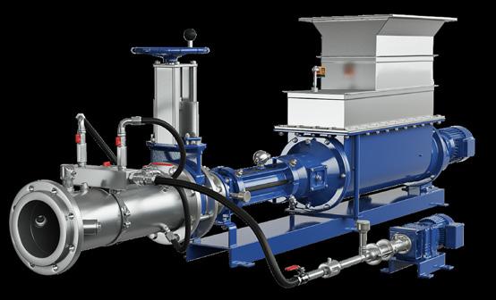
In the field of progressive cavity pumps, Smart Air Injection is the efficient solution for pumping dewatered sludge with a dry solids content of 20-40% over long distances: effortlessly, with low pressure and up to 1,000 m.
y Low investment costs and reduced operating costs y Long lifetime due to low pressure level y Closed system solution with a small footprint y Simple integration into existing automation and control systems y Energy efficient due to Smart Conveying Technology
Construction complete on SA desalination plant
Residents in remote outback town, Oodnadatta in South Australia now have access to clean drinking water after SA Water implemented a newly constructed desalination plant.
The new small-scale reverse osmosis plant, stationed on Kurka Drive, can produce up to 210,000L of safe and clean drinking water each day for residents.
SA Water General Manager for Sustainable Infrastructure, Amanda Lewry, said that the new desalination plant marks an important milestone for the outback town.

The containerised facility can produce up to 210000 litres of clean and safe drinking water. Image courtesy of SA Water
“This project will make such a difference to the daily lives of our customers in Oodnadatta, and to see a new supply of drinking water now flowing to their taps is a significant milestone,” Ms Lewry said.
“The plant itself was assembled inside of a protective container in metropolitan Adelaide, before making the 1000-plus
kilometre journey to Oodnadatta via truck for final installation.
“Sourcing water from the Great Artesian Basin, the plant uses reverse osmosis to treat and remove salt and other impurities commonly found in the state’s groundwater supplies, before the end product is piped to local customers for use in their kitchens, bathrooms, laundries and gardens.”
SA Water’s previous network throughout Oodnadatta had been designated as a non-drinking supply with residents having to source their drinking water from private rainwater tanks, water carting, bottled products and localised desalination units.
“We are proud to have worked closely with the Oodnadatta community on delivering their new tap water, and the benefits it will bring,” Ms Lewry said.
“Travellers visiting the outback town will also be able to top-up their reusable drinking bottles thanks to the town’s new smart drinking water fountain, designed with a solar-powered chilling system to keep the water cool throughout the hot summer months.”
Progress is also being made on the delivery of desalination facilities in the remote townships of Marla and Marree, to be delivered over the course of the 2020-24 regulatory period.
Innovative solutions to solve your environmental pollution problems
MAIRS Technology uses traditional technologies and innovative engineered solutions to service a range of industries and customers to help manage their environmental needs and systems, whilst meeting environmental and health safe regulations, and health of nearby communities.
Our capabilities:
• Project Management Services
• Engineering Service Support
• Equipment Spares Supply
• Construction services and supervision
• Sub-contract management
• Commissioning and training
• Asset inspections and reports
• Asset maintenance and management planning
• Optimisation and system improvements

03 9028 8080 sales@mairstech.com www.mairstech.com


Roto KWIK Pumps
Specially Designed for Fast-Track Maintenance
Because Every Second Matters
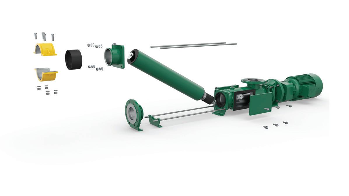
Clamp
Specially designed clamp enables quick removal of rotor and stator without dismantling discharge line.
Split Coupling Rod
Enables quick dismantling of pumping elements from the coupling rod.
Dual Inspection Windows
Provides access to split coupling rod and also allows removal of any blockage.
SYDNEY WATER COMMENCES
$185M wastewater network upgrade
Sydney Water has announced the commencement of a $185 million upgrade to the Richmond wastewater network to support the region’s rising population, with the major works expected to create 200 local jobs.
The project will include a new wastewater pumping station and the construction of a new seven-kilometre main, which is expected to transfer wastewater from North Richmond to Richmond.
The improvements are in keeping with Sydney Water’s goal of building critical water and wastewater infrastructure to enable the construction of future dwellings in Greater Sydney.
Senior project manager, Greg Cable, said that the planned works will play a major part in ensuring a more sustainable future.
“Growth is set to increase by 70 per cent over the next 30 years. The completed upgrades will help future proof the region’s rapidly growing population.”
The project will contribute to circular economy benefits by expanding water recycling capacity at the site and the production of biosolid matter for reuse.
Upgrades to the Richmond Water Recycling Plant are expected to be completed in 2026.


A POWERFUL PARTNERSHIP

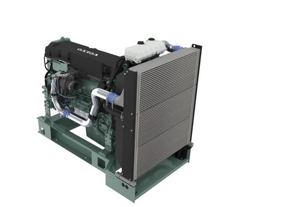
Volvo Penta. Robust, fuel efficient industrial diesel engines that keep running even in the toughest conditions. Easy to install, operate and maintain. A powerful partnership you can trust all the way from the drawing board throughout the operational life of your engine. Competitively priced complete power-pack units ready for delivery Australia wide with a local support team on hand 24/7. To find your nearest dealer visit www.volvopenta.com

Davey Water Products acquired for $65M
Global water treatment and pool equipment manufacturer, Waterco Limited (Waterco), has acquired Davey Water Products through a $64.9 million transaction, completed on 1 September 2023.
The acquisition of Davey Water Products (Davey) – a subsidiary of GUD Holdings Limited (GUD) – has cemented Waterco as one of the largest Australian-owned and operated entities in the water industry.
With a combined 131-year history in the multi-billion-dollar global water industry, the acquisition will enable Waterco to expand its reach while providing increased market presence and growth opportunities for shareholders.
Waterco Founder, Executive Chairman and Chief Executive Officer, Soon Sinn Goh, said, “We are excited about the potential synergies between Waterco and Davey. By working together, we believe we can create a stronger and more competitive water treatment and pool equipment business.
“We believe this approach would be less disruptive than a full merger or integration, but will still lead to significant benefits for both companies.”
The company will focus on three key areas: increased market share, enhanced product offerings and improved operational efficiency.
Waterco is taking a long-term view of its investment in acquiring Davey. The company is committed to sustainable growth and believes that this acquisition will help it achieve its goals of becoming a global leader in the water technology industry.
"By adopting a long-range outlook, Waterco is positioning itself for success in the years to come," Mr Goh said.

“Davey is an iconic Australian brand; we are respectful of its long heritage and understand the need for careful planning and execution in order to minimise disruption to the company's operations and reputation.”
Davey has been manufacturing water pumps and other water treatment products in Australia for nearly 90 years, a tradition Waterco intends to keep.
“We are proud of its local manufacturing capabilities, which we believe are essential for the company's future success," Mr Goh said.
Davey has a team of experienced and skilled engineers and technicians who are dedicated to creating high-quality products that meet the needs of its customers.
Davey COO Peter Wolff says the company is confident that this combination will be successful.
“We are committed to working with Waterco to create a winning team and leverage the strength of both brands,” he said.
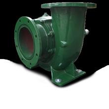
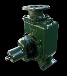
CROSSLEY CHINA PUMPS
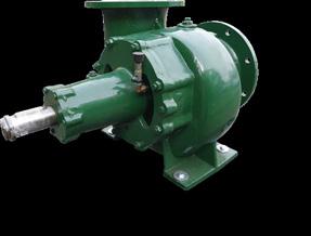
Welling & Crossley can now supply a range of self-priming and mixed-flow China Pumps. Ranging from 100mm (4”x 4”) to 300mm (12”x 12”).
Mixed-flow pumps feature:
• Table D flanges
• Oil bath / Mechanical seals
• Stainless steel shaft

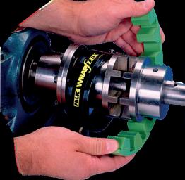
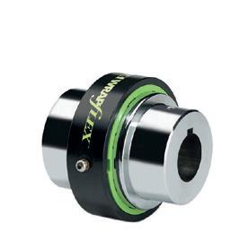
Wrapflex and Omega
Not your average pump drive

• The benchmark in Elastomeric Couplings for Pumps
• Engineered materials and patented designs to increase longevity and reduce reactive load on equipment
• Flexible enough to accommodate moderate misalignment and vibration
• Split elements for ease of in-situ replacement
• Stocked in Australia for quick and stress free access


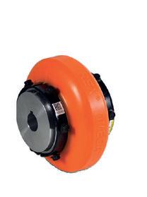
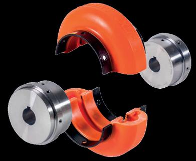
Orange Peel®
• Coupling and Shaft Guarding
• Configurable to fit most applications
• Powdercoated steel and Polyethylene variants
• Multiple sizes and styles
• Off the shelf availability
VALE ARTHUR CONNOR
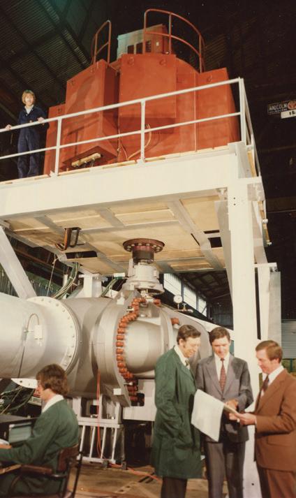

Respected engineer and pump industry pioneer, Arthur Connor, has passed away. Arthur made a significant contribution to the pump industry over several decades, including the early days of the PIA’s precursor, the Australian Pump Manufacturers Association (APMA).
Arthur was part of the senior executive team at Kelly & Lewis, a leading pump manufacturer during the 20th century that at its peak employed
nearly 500 staff at manufacturing facilities in Springvale, Victoria. As a pump hydraulics designer, Arthur was responsible for the design of many major pump projects for the water, power generation and sewage sectors throughout Australia.
His efforts and involvement in the pump industry have also been recognised by the Institution of Engineers, Australia, who elected him a Fellow following his retirement in 1993.
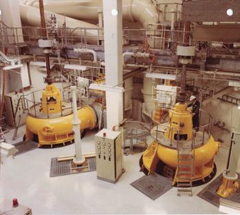
Arthur was well-respected throughout his life and career and will long be remembered for his dedication and contribution to the industry.

When Quality and Innovation come together.
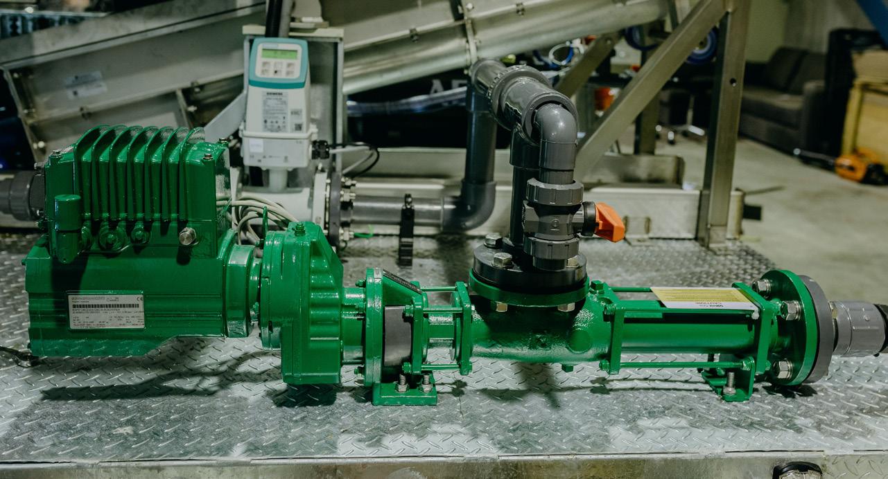
How can we help you achieve your fluid transfer goals?
By listening to your operational requirements, and being in tune with your pump application’s demands. We provide efficient and sustainable solutions using the latest of drive system technology from our vast range of products.
Worrying


WEG LAUNCHES NEW MOTOR LINE combining efficiency with sustainability
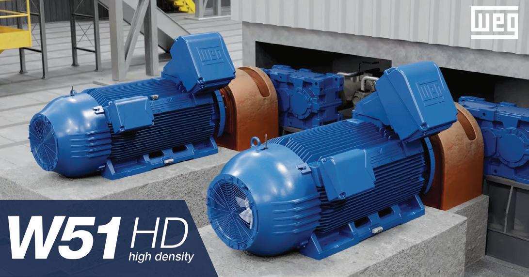
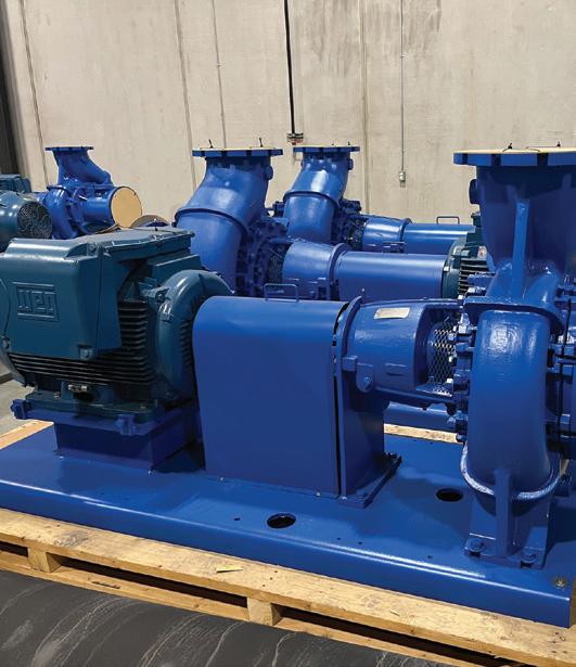
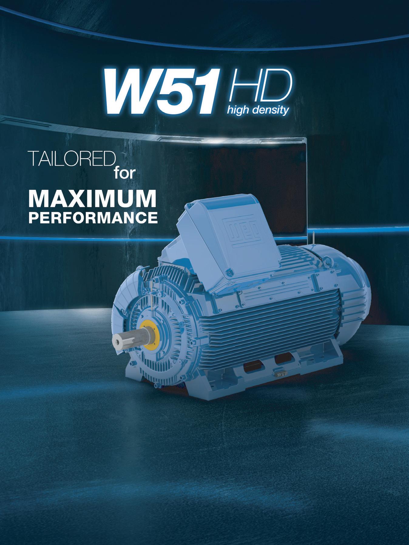
WEG has announced its new W51 High Density (HD) motor line, which utilises high density technology to focus on high performance and lower resource consumption.
The W51 HD motors are compact, customisable and suitable to solve a great variety of applications, delivering better performance and longer durability. Available in low and medium voltage, and in IEC 315 to 450 or NEMA 5000 to 7000 frames, the W51 HD motors have a modern concept, in line with the market expectations for highly efficient products and rational use of natural resources due to their reduced size and weight.
The technology behind W51 HD
In order to deliver more power in a smaller size and weight, the motors have a cooling system with an exclusive design and a larger heat exchange area, patented by WEG. The bearings are also designed with an optimised cooling system to ensure
greater reliability, which translates into low maintenance requirements and longer service life. In addition, its innovative acoustic system dramatically reduces noise levels to some of the lowest on the market.
Achieving maximum performance
The W51 HD line is developed with advanced engineering tools and features state-of-the-art technology that allows it to deliver performance above the market standards.
This line is designed to be interchangeable with other motors, flexible to install and highly customisable according to the requirements of each application. It also offers a wide range of accessories, further adding to its versatility.
For more information, scan the QR code to watch the W51 HD Motor product video.

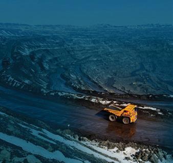
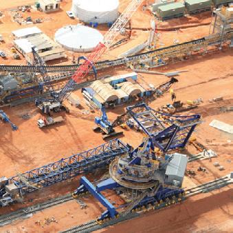
Deliver more power in less space: this is the goal of the WEG W51 HD line. The motors with High Density technology are compact and customisable, meet the new demands of the market, and adapt easily to the most diverse types of applications, delivering better performance and greater durability.
Ebara Pumps and Hayward Gordon JOIN FORCES
Ebara Corporation Japan has recently acquired 100 per cent equity of the Hayward Gordon Group, based in Toronto, Canada.
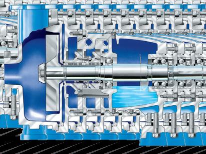
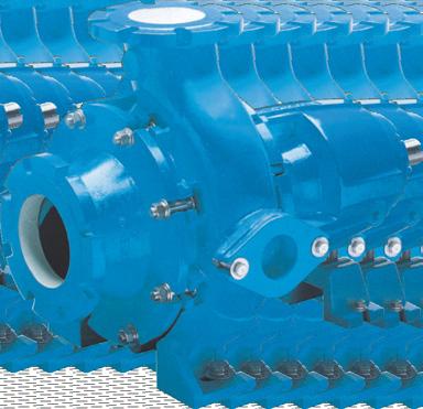
For more than seven decades, Hayward Gordon’s pumps, mixers and equipment have been a premier choice in North America for pumps and mixers for the water management, mining, chemical, energy, oil and gas, mineral processing, food and beverage, and wastewater treatment industries.
The acquisition is a tremendous opportunity to expand Ebara’s product portfolio to include Hayward Gordon’s heavy-duty process pumps and extensive line of mixers; and to develop Hayward Gordon’s manufacturing capabilities and the synergies of the Ebara Corporation worldwide sales network.
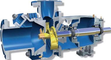
Hayward Gordon has a range of specialised pumps and mixers for solid handling, which includes the – XCS screw impeller pump from 100mm
to 400mm discharge. This pump is suitable for large or stringy solids, shear sensitive mediums and has inherent low NPSHR characteristics.
Other specialised pumps in Hayward Gordon’s range include the Chopx series of chopper pumps that perform the dual function of cutting and pumping, making them ideally suited for applications that require reduction of solids size and/or protection of downstream equipment. Pumps are available in pedestal mount, submersible and vertical line shaft or cantilever design.
The third unique pump in this highly specialised range of Hayward Gordon solid handling pumps is the Torus recessed impeller pump. These pumps can handle solids with a maximum 200mm sphere size, subject to the discharge size of the pump. This range has 16 models and wet end


parts are also available in a number of materials including CD4Mcu, 28 per cent chrome iron, NiHard and Super NiHard – for both corrosion and abrasion resistant applications.
In addition to these three popular solid handling pumps, Hayward Gordon also manufactures a specialised vertical jacketed molten sulfur pump with the option of vertical bearing or cantilever configuration.
As well as the Hayward Gordon pump range the company also manufactures a range of mixers suitable for a variety of industries, including wastewater management, mining, pharmaceutical, chemical, and food and beverage.
About Ebara Corporation.
Ebara Corporation was founded in Japan in 1912 as a manufacturer of industrial pumps. Today, as a group it consists of more than 100 companies in six continents, with a workforce of more than 19,000 team members in companyowned and Japanese-managed factories that cover ten countries and four continents.
The huge scale of production and distribution is matched by a constant commitment to research, development and design of new products and the modern technologies for the manufacturing of them. Ebara products have gained a worldwide reputation for their technology and quality.
Ebara Corporation and Hayward Gordon now working together to provide high-quality, cost-effective, harsh duty pumps and mixers for the most challenging fluid applications in the most demanding industries across the globe.


DRIVE SYSTEMS OPENS NEW QLD OFFICE
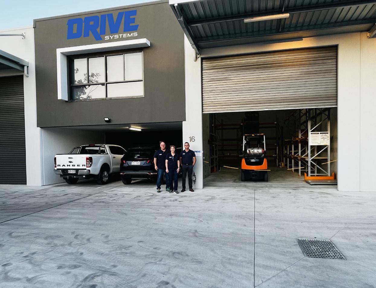
Long term PIA member, Drive Systems, has recently opened the doors to its additional premises in Crestmead, Queensland.
This wholly Australian-owned business first opened its Melbourne head office in early 2017, and with its steady increase in presence across Australia, it was only a matter of time before it expanded into one of the country’s most important pump markets.
State Manager, David Harker, said, “We chose Crestmead as it is located in the western freight corridor of Brisbane. From here we can service the whole of Queensland with whichever freight method is required.”
Mr Harker has more than 27 years of industry experience and is a true power transmission professional, and boasts an excellent knowledge of the full range of couplings. Be it disc, grid, gear, or elastomeric couplings, David can help you with the correct coupling selection and supply ex stock.
“It's not just motors, gearboxes and couplings, we are also stocking Mayr Brakes and Torque limiters, exclusively imported from Germany. Mayr is an industry leader and an excellent fit for our ‘quality first’ supply partner program,” Mr Harker said.
Drive Systems’ founder, Dean Hansen, said, “The overwhelming majority of our suppliers are based in Europe – CMD France, Esco Belgium, Siko Germany, Mayr Germany Mini Motor Italy, and Resatec Switzerland. Quality is our cornerstone, but our focus is on more than that. Choosing long-established, reliable manufacturing partners not only ensures quality products for our customers, but also supply chain stability. There is a reason why other brands are cheap, and it’s not always just in the quality of the manufacturing. Service and reliable delivery are important parts of the supply chain package.
A national leader in mechanical power transmission, Drive Systems has customers right across the country, and stock holdings in three states. This expansion into Queensland complements the company’s recent appointment of Motor Gear Box Products (MGP) as its exclusive distributor in Tasmania.

CHILLER HEAT PUMPS LEADING THE WAY IN SUSTAINABLE BREWING
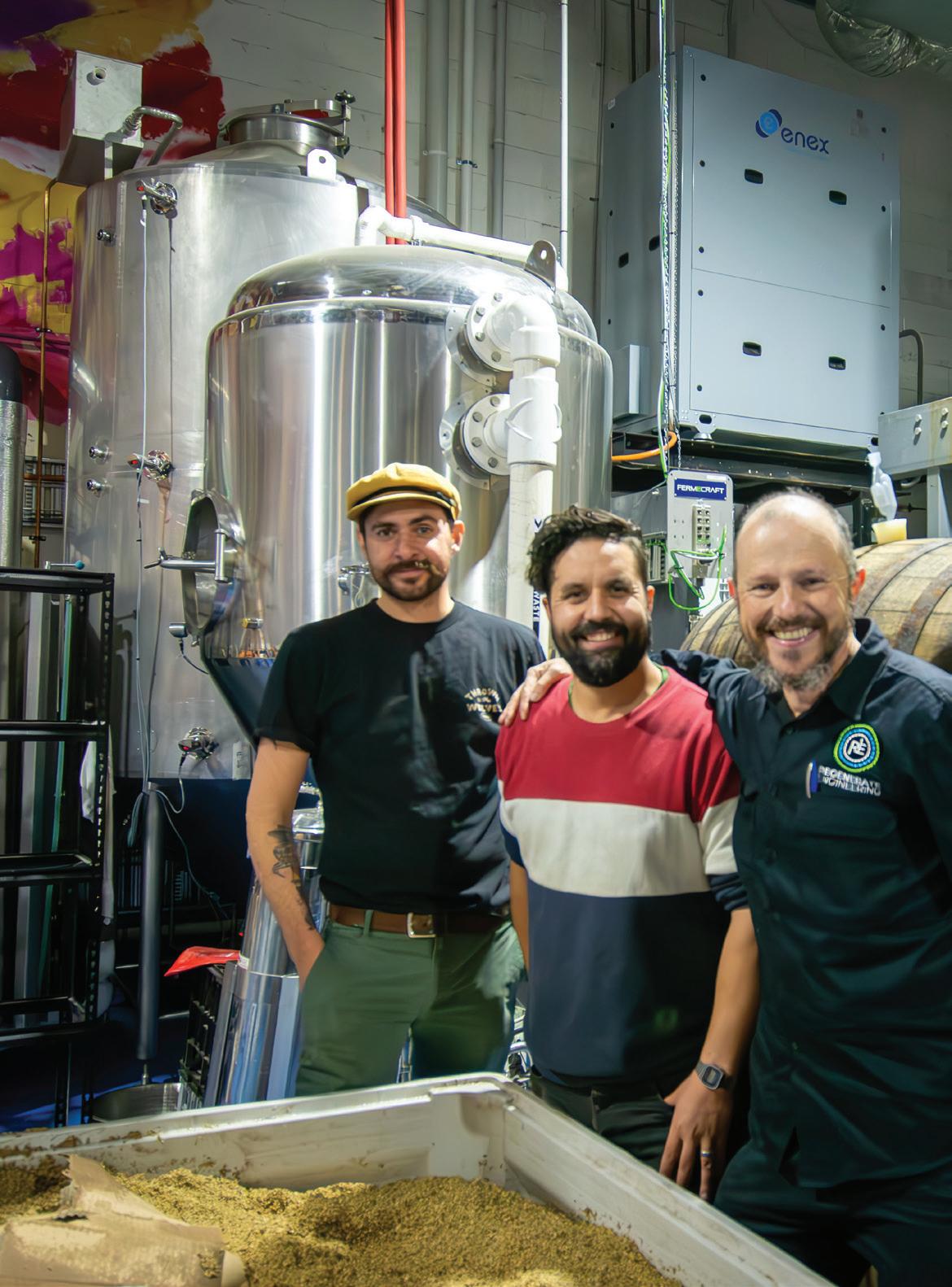

Australians have always loved their beer. Increasingly they are loving craft beers from smaller, independent brewers, with more than 600 independent brewers now operating across the country. Despite their popularity, many of these smaller operations face an uncertain future due to the pressure of rising energy costs and the energy intensive nature of brewing. However, Melbourne’s 3 Ravens Brewery is demonstrating how highly efficient heat pumps and some careful planning can allow you to produce a lot more beer for your energy dollar.
What started out as a small brewing exercise to produce a custom beer for a wedding, has now seen 3 Ravens become a leading independent Australian beer name. The 3 Ravens team are focused on continued growth, but, true to their values, want to ensure that as they increase production, they are also reducing their impact and giving back to their local Thornbury community. Thus, the brewery sought a better solution than upgrading the business-as-usual (BAU) equipment to cope with the planned larger volumes.
For 3 Ravens General Manager, Nathan Liascos, sustainability has always been really high on the brewery’s business agenda.
“We see sustainable brewing as not just vital for the future of our business, but the wider industry. In planning for growth we wanted to go beyond the basic green measures and explore sustainable practices to maximise efficiency and lead the way in renewable energy innovation in our industry,” Mr Liascos said.
To do this, 3 Ravens engaged energy consultancy, Regenerate Engineering, to analyse the existing facility and processing equipment to better understand where and how the energy was being used and how it could be used better.
Director at Regenerate Engineering, Jon Fettes, said, "Brewing beer is extremely energy intensive, using a lot of energy for cooling and heating processes.
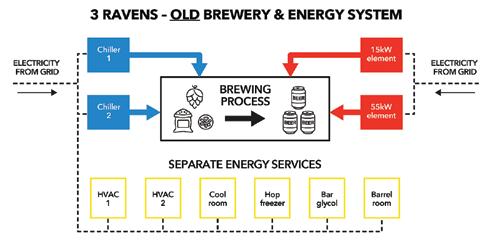
“Like at many other breweries, 3 Ravens had a fairly balanced mix of heating and cooling being provided by different pieces of equipment. But the waste heat from one machine would make other equipment work harder to deliver their services as well as making the workspace uncomfortable,” Mr Fettes said.
A more efficient approach
Although 3 Ravens has always been an electric-only brewery, its electric processes have not been very efficient. Before the recent upgrade, a 15kW resistive element was used to preheat filtered water (hot liquor) and then 55kW elements were used to further heat then boil the wort produced from that hot liquor and the mash ingredients. Two chillers were operating independently to produce chilled glycol treated water and chilled filtered water (cold liquor) to operate all process and ingredient cooling services. Also, the site had several ageing electric reverse cycle R22 HVAC split systems to provide space cooling and a cold storage facility.

Sticking with the existing equipment while ramping up production would have seen the brewery’s energy costs skyrocket and required a costly upgrade to the site’s electrical capacity. Continuing with the BAU equipment would also have created a significant liability with the HVAC equipment as the phase-out of harmful R22 refrigerants continues.
Regenerate Engineering and 3 Ravens approached the expansion and energy upgrade in a holistic and integrative way to maximise benefits to the business and the environment. With its focus on renewable energy and sustainability, planning for the energy project was aided by pre-feasibility and feasibility studies managed by the Australian Alliance for Energy Productivity (A2EP) and funded by the Australian Renewable Energy Agency (ARENA) through its Advancing Renewables Program.
The feasibility studies included a detailed mass/energy balance of the process, applying pinch analysis principles to the analysis and development of options. The analytical work detailed how the proposed equipment could be integrated into the current plant and the extensive upgrades that would be required. An expansion of the initial proposal into space heating and cooling (HVAC) services for public spaces at the site was recommended due to further thermodynamic and cost efficiencies, which were identified in the process.
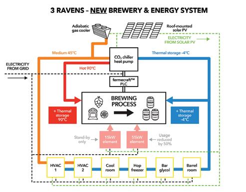
In the feasibility studies, a CO2 chiller heat pump was identified as a key piece of equipment. The chiller heat pump – a single cycle, flexible CO2 refrigerant chiller with advanced heat extraction – would largely replace the inefficient and separate heating and cooling processes.
Before the equipment changeover in the brewing hall, there were a number of other important, complementary measures that were needed to address space heating and cooling issues and maximise the benefits of the wider project. First, 3 Ravens installed a “cool roof” to reduce thermal impacts from outside climate on the internal climate to increase comfort and reduce the work required by air conditioners. Then 74kW of solar

The challenges of using heat from chillers as process heat
All breweries use chillers that have a glycol tank as storage. Every chiller, by virtue of the laws of physics, makes more heat than cold, but traditionally the heat is airborne and a nuisance rather than a resource. Heating processes have rarely been integrated with cooling in brewing operations before. Typically, heat pump systems work best operating in a constant state (optimised with variable speed systems), however, brewing is by nature a batch process. Where the heating and cooling services come from the same machine it is a challenge to ensure that the system can produce both thermal streams where they are not required at the same time. While the brewing is still a batch process, the key to success in making this work is system flexibility, redundancy, increased storage and better use of heat exchangers in the process. This can ensure that the chiller heat pump can run for quite long periods. All these aspects will be driven and managed at 3 Ravens through advanced programmable logic controller (PLC) from Fermecraft, which utilises Industry 4.0 technology to automate the brewing to maximise energy efficiency.
Applications and reduction of resistive heating duty
Using the thermal model with scenario modelling, operational range was analysed according to the worstcase usage profiles of different brew recipes and schedules – including sour beers, which require cooling and steeping after inoculation and then re-boiling after an initial short boil. Seasonal performance of the CO2 chiller heat pump system was accounted for, as efficiency – or coefficient of performance (COP) – varies according to ambient conditions. Further, when
HVAC is added, the system needs to be robust enough to withstand the seasonal extremes and the demand that this adds. It is worth noting that the cool roof installed at the facility is expected to increase the more efficient “cool weather” CO2 season by helping the roof-mounted adiabatic gas cooler run more efficiently.
Current state of play and expected benefits
As of June 2023, the new system has been installed. It will be closely monitored and further tweaks and adjustments will be made as 3 Ravens adds brewing automation features and commissions the space heating and cooling. It is anticipated that the impact of the system will be a huge improvement in energy productivity, with 3 Ravens looking to quadruple its production over the next few years without a corresponding increase in energy consumption. This will mean greater financial sustainability for the business and less emissions per beer for their climate-conscious customers.
“These energy focused upgrades have enabled us to ramp up production, control our costs and significantly reduce the emissions associated with each beer we brew. Something that’s really important to both us and our customers,” Mr Liascos said.
“We hope that our actions inspire and motivate other breweries to take the same path and reinforce the importance of safeguarding our environment for generations to come.”
“What’s exciting about this project is that it is highly scalable and replicable – although modelling and plant choice will need to be adjusted to suit electrifying gas-powered process heat,” Mr Fettes said. “Rolled out across the brewing industry, the energy and emissions savings would be substantial.
Read the full detailed case study for this project on the FutureHeat website: www.futureheat.info/post/3-ravens-brewery-melbourne-heat-pumps-for-beer-production
SUSTAINABLE PUMPING: LEAVING THE PLANET TO OUR GRANDCHILDREN
By Robert Welke, WATER PUMPING INSTITUTEOur current model for calling tenders for pumping systems is based on price. The lowest price pump system is usually also the highest emitter of greenhouse gases, which does not bode well for our grandchildren’s future.
Sustainable pumping can be defined as a balanced mix of environmental responsibility and economic sustainability. That is, the minimum energy input (reduced CO2 emissions) for the maximum work output (return on investment) amortised over say 25 years.
It can be graphically described by the chart shown (Figure 1).
The key components of sustainable pumping include:
• Cost of energy
• Volume of water pumped
• Total pumped head
• Pump and motor efficiency
• Variable frequency drives
Now, the pump industry could be forgiven for believing that the pump and motor have the major roles to play in influencing sustainable pumping. After all, pump and motor efficiency play a role in converting energy into useful work, right?
No, it’s the hydraulics that has the major influence in sustainable pumping. So, then, what if we keep the water velocity down, and design all our pipeline systems to 1.5m/s max velocity, that will fix that, right?

Wrong, in fact, very wrong! The ubiquitous 1.5m/s rule of thumb for maximum water velocity has no place in hydraulic calculations for sustainable pumping.
Case study 1
Let’s look at two examples of a pump selection, both pumping 32l/s through 300m of pipe, over 25 years:
Pump A runs for 100 per cent of the year, 24/7/365, and pumps 1000ML/yr through PVC pipe. This may be a water treatment plant pump, for example.
Pump B runs for 15 per cent of the year and pumps 150ML/ yr through PVC pipe. This may be a sewage pump or a 25Ha orchard irrigation pump, for example.
Both pipes are derated to C Value = 130.
The optimum diameter for pump A system is 250NB with a water velocity of 0.59m/s and head loss of 0.42m (pipe friction only), with 1.64kWh/ML energy consumption.
The optimum diameter for pump B system is 200NB with a water velocity of 0.9m/s and head loss of 1.24m. (pipe friction only), with 4.84kWh/ML energy consumption.
If pump C had been selected with a water velocity of 1.5 m/s, its headloss would be 4.34m resulting in 16.95kWh/ML, or a 1000 per cent increase over pump A. And its more than likely that this is what would have been designed and supplied in this instance because of the existing competitive tendering process. Perhaps even higher velocity than 1.5m/s!
No one denies the need for the role that pumping water has in our life. But how efficient are these pumping systems at delivering today’s needs while being environmentally friendly enough to preserve the planet for our grandchildren?
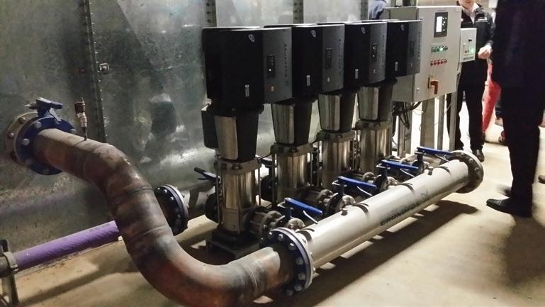
Because pump A runs continuously, its pipe size is configured larger, with low head loss and therefore lower motor kW than pump B, saving 23t of CO2 emissions so that your grandchildren can have a future on this planet
Now, that’s sustainable pumping!
Case study 2
A saving of $18,800 (52 per cent) per annum in pumping costs was achieved on this dairy centre pivot irrigation scheme in Victoria, Australia in 2018, using sustainable pumping principles.
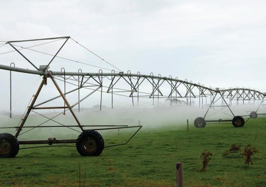
An audit by the author found the pump running off BEP at 57 per cent efficiency, and the rising main from the pump to the centre pivot was 150NB PVC with 63m head loss.
The pump was replaced with a fit for purpose selection with 78 per cent efficiency.
The pipeline was replaced with 200NB with a reduction in pumped head of 25m. The combination of the replacement pump and larger pipe netted $18,800pa reduced electricity cost, with two-thirds of that attributed to pipeline friction reduction.
It reduced CO2 emissions from 180t per year to 80t per year, saving 100t of CO2 each year from going to the atmosphere.
That’s sustainable pumping!
Future of pumping water
Our pumping industry is an important component of the water industry as a whole.
And yes, pump and motor efficiency do have a small role to play in pumping sustainability. However, it is pipeline hydraulic efficiency that largely determines pumping system sustainability.
Should we be looking to review our tendering model of lowest cost, and replace it with lowest pumping emissions tenders?
Perhaps we could be working towards some form of mandate to regulate pumping systems to be designed with limited greenhouse gas emissions, so our grandkids have a better future to look forward to.
Author Robert Welke worked at SA Water for 25 years conducting extensive pumping and pipeline energy efficiency monitoring of its 130,000kW major pumping and pipelines infrastructure. Robert established WATER PUMPING INSTITUTE (2003), a pumping and hydraulics’ consultancy based in Adelaide, which applies his SA Water knowledge plus experiences in other water industry groups. He has never sold product and has spent his whole career with a pressure gauge in one hand, flowmeter in the other, and now offers auditing and training courses serving clients in Australia and New Zealand.
For more information on WATER PUMPING INSTITUTE and its training course Pumping System Master Class for Water & Wastewater, visit www.talle.biz/wpibillwww.html
USING UNIQUE GEOMETRY AND AN INNOVATIVE SETTING SYSTEM TO SAVE ENERGY IN PC PUMPS
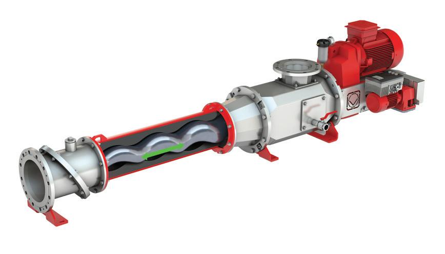
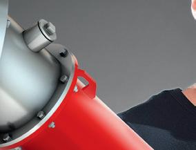
The HiCone supports pumping capacities of up to 290 m3/h, and its revolutionary, conical shaped rotor and stator as well as its clever adjustment system allows for high profitability and durability.
Brad Adams, Managing Director at Vogelsang Pty Ltd said, “With the HiCone, we are once again setting new standards for progressive cavity pumps. We have met the demands of our customers for reduced life-cycle costs and longer service times with the further development of our technology.”
Readjust instead of changing parts
With conventional progressive cavity pumps, if a gap arises between rotor and stator due to wear in operation, the capacity drops. This often means a sudden, drastic fall of the pump performance and the replacement of the rotor and stator. Conversely, the HiCone allows axial readjustment of the rotor. Its conical shape ensures that the gap is regulated, meaning that the pump is back to its original condition and the pumping capacity returns to 100 per cent. Instead of the costly and time-consuming process of changing parts, the problem can be solved with a quick and easy adjustment made during ongoing operation.
Vogelsang GmbH & Co. KG has launched HiCone progressive cavity (PC) pump, which combines a conical form with an innovative setting system to conserve energy and significantly extend its service life.
Combined with Vogelsang’s integrated QuickService concept, this significantly reduces life-cycle costs for the user and higher pump availability, since there are no elaborate service deployments.
A unique swivelling mechanism
If replacement is nevertheless necessary, the rotor-stator unit is swung out and can then be renewed either as a unit or individually. A wearresistant sleeve, which does not need to be unmounted to change parts, protects the sturdy cardan shaft.
Lower electricity requirement for increased energy efficiency
Thanks to the clever adjustment system, the rotor and stator can be optimally positioned to each other according to operating parameters, such as pressure, temperature and viscosity. This results in lower power consumption, which reduces the electricity requirement. Wear is also reduced at the same time.
Automatic start-up delivering higher efficiency
In addition, the HiCone’s automatic start-up saves power. The rotor and stator are positioned in such a way that there is only minimal clamping between them. This means that a smaller motor
is needed to ramp up the pump than in conventional progressive cavity pumps, which reduces the power requirement when starting the pump to a minimum. This increases the energy efficiency and reduces the costs for power electronics. The result is lower electricity costs and reduced procurement expenses for users. The start-up process is fully automatic without the need for additional control. The clamping between the rotor and stator can be adjusted during the entire service life at the touch of a button or at the click of a mouse from the control room.
Online monitoring of the status
Mr Adams said that another advantage for users is that they can view the status of the pumping elements in a real-time display.
“Instead of being surprised by a sudden failure, they receive continuous information and can plan parts changes in advance,” Mr Adams said.
“Our customers need technology that is long-lasting and can be flexibly adapted to differing pumping tasks and operating parameters. The HiCone gives them a highly efficient pump, which can be individually adjusted and readjusted.”






FULL POWER UNTIL THE END




vogelsang.info/au/hicone


VOGELSANG
– LEADING IN TECHNOLOGY
vogelsang.info


Multiplied service life and significantly reduced life cycle costs: With its conical rotor and stator geometry, an innovative adjustment system, and its intelligent automatic start-up, the new HiCone ® stands for maximum efficiency. Start for a new era with Vogelsang and be one of the first to benefit from the advantages of the superior HiCone ®


ENERGY SAVING SLUDGE PUMPING SYSTEM FOR wastewater treatment plants
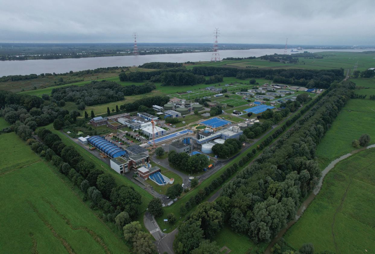
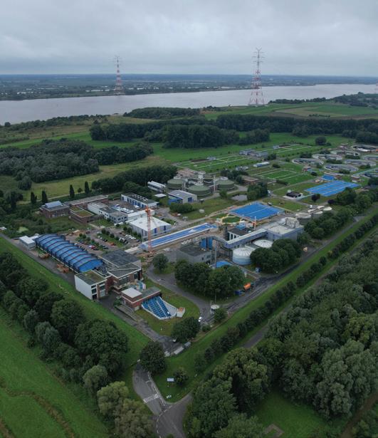
Smart Air injection (SAI) is a new sludge pumping system that is offering wastewater treatment plants (WWTP) a costeffective and energyefficient solution. Here we look at how this technology is reducing the carbon footprint of the Hetlingen WWTP, near Hamburg, Germany, which is now saving around 20–25 per cent of energy in thick sludge pumping alone.
Environmental and economic considerations play a decisive role when municipal water utilities are considering the purchase of new pumping technology. Worldwide, SEEPEX's energy-efficient and lowmaintenance SAI-system ensures that thick sludge reaches its destination at low pressure, even for distances longer than 1km.
Two conveying technologies for a customised solution
SAI is a customised system solution that uses a combination of progressive cavity pumping and dense phase pneumatic conveying to discontinuously transport short plugs of highly dewatered sludge in a particularly
energy-efficient manner. In principle, it's just like the good old pneumatic mail. As a result, friction losses only occur along these plugs and not in the entire pipe, resulting in numerous unique advantages, such as the ability to transport sludge for up to 1km with a low-pressure pump and PN10 piping.
For water utilities in Australia, SAI poses an alternative to conventional processes, and has been tried and tested overseas for years. The energy saving it provides means that SAI can quickly pay for itself, and more than 80 customers already benefit from this innovation, which is patented in Europe, the USA and China.
Implementation at the Hetlingen WWTP
Located north-west of Hamburg, Germany, the Hetlingen WWTP serves more than 40 towns and communities, treats more than 31 million cubic metres of wastewater per year and processes about 46,000Mg of sludge per year – which is anaerobically stabilised, dewatered in centrifuges and pumped into silos. After anaerobic stabilisation, the digested sludge is dewatered in centrifuges in a separate building and then falls through a hopper into the pump cellar. From there, it was previously pumped by two piston pumps to two silos located 60m away and 30m higher. The dewatered sludge was then trucked to an off-site incinerator for thermal recovery. When the centrifuges were replaced in a planned rebuild, the piston pumps were found to be undersized. In addition, maintenance requirements and energy costs were very high.
Hetlingen WWTP turned to SEEPEX when it needed to improve its solids handling technology following the replacement of centrifuges and feed pumps. The main challenge was to find a new thick sludge conveying system that would fit into the existing infrastructure along with the re-planning of the thickening sludge silos. The result, as envisioned by the plant operators, was a system that would minimise maintenance and energy costs, as well as downtime for servicing. The goal was to significantly reduce the total cost of ownership (TCO) in direct comparison to installed piston pumps. In addition, the wastewater authority wanted a much more flexible system that would be suitable for future upgrades. As the centrifuges for dewatering had already been ordered, a quick solution had to be found to transport the 5–15m³/h of sludge to the two silos within the existing infrastructure and without interrupting operations.
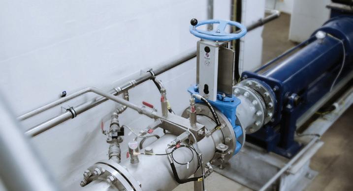
Smart Air Injection including sensors, compressed air connections and lubricant injection points.
After extensive consultation and a comprehensive review of the plant's specific conditions, SEEPEX experts set about developing a solution that was perfectly tailored to the plant. In the end, SEEPEX was chosen as the general contractor to supply and install two redundant systems. The scope of supply included installation, piping and cabling. Delivery was completed within six months. The bespoke SAI system was supplied with a hopper pump (BTHE 130-12) with a moveable stuffing part for easy removal and access to the rotor side joint and screw conveyor (Rotor Joint Access), a dosing pump for lubricant supply, a compressed air system consisting of a compressor and air receiver, and a control cabinet with integrated control. In addition, SEEPEX installed two separate pipelines (PN16, DN250 in stainless steel) over a length of 90m (60m horizontal, 30m vertical), including the necessary sensors and isolation valves. The integrated automation technology (SAI controller) allows the two outdoor silos to be fed as required.
Pneumatic dense phase conveying with supporting lubricant minimised friction losses in the pipeline. The characteristic pressure behaviour of SAI is also evident in Hetlingen, where the
pipeline pressure in operation is only 2–3bar. In contrast, hydraulic operation using a piston pump was achieved at up to 70bar. By reducing the operating pressure, it was possible to use a PN16 stainless steel pipeline. Due to the low pressure level compared to conventional solutions with much higher operating pressures, it was possible to save costs in the purchase of piping.
In addition, the low operating pressure significantly increases the service life of all pump and pipework components. Overall, SAI saves around 20–25 per cent of energy per year compared to a piston pump. The Rotor Joint Access maintenance concept, with its moveable stuffing part, simplifies pump maintenance and saves costs. It allows quick and easy access to the rotor-side joint for easy maintenance without dismantling the pressure branch or stator. In this way, the innovative SAI system solution greatly simplifies maintenance. With these new pumps up and running, the Hetlingen WWTP will have to intervene less frequently during operation and the entire operational side runs more smoothly. Significant energy savings during pump operation will reduce the plant’s carbon footprint, boosting their climate protection measures.
SEEPEX is one of the world's leading specialists in the field of pump technology. Its product portfolio includes progressive cavity pumps, pump systems and digital solutions. SEEPEX also offers innovative solutions for conveying aggressive or abrasive media with low to high viscosities. Since 2021, SEEPEX has been part of the Ingersoll Rand Group, a global supplier of mission-critical flow creation and industrial solutions, consisting of more than 40 renowned brands. Ingersoll Rand Inc. (NYSE:IR), driven by an entrepreneurial spirit and ownership mindset, is dedicated to helping make life better for our employees, customers and communities. For more information, contact SEEPEX or visit www.IRCO.com

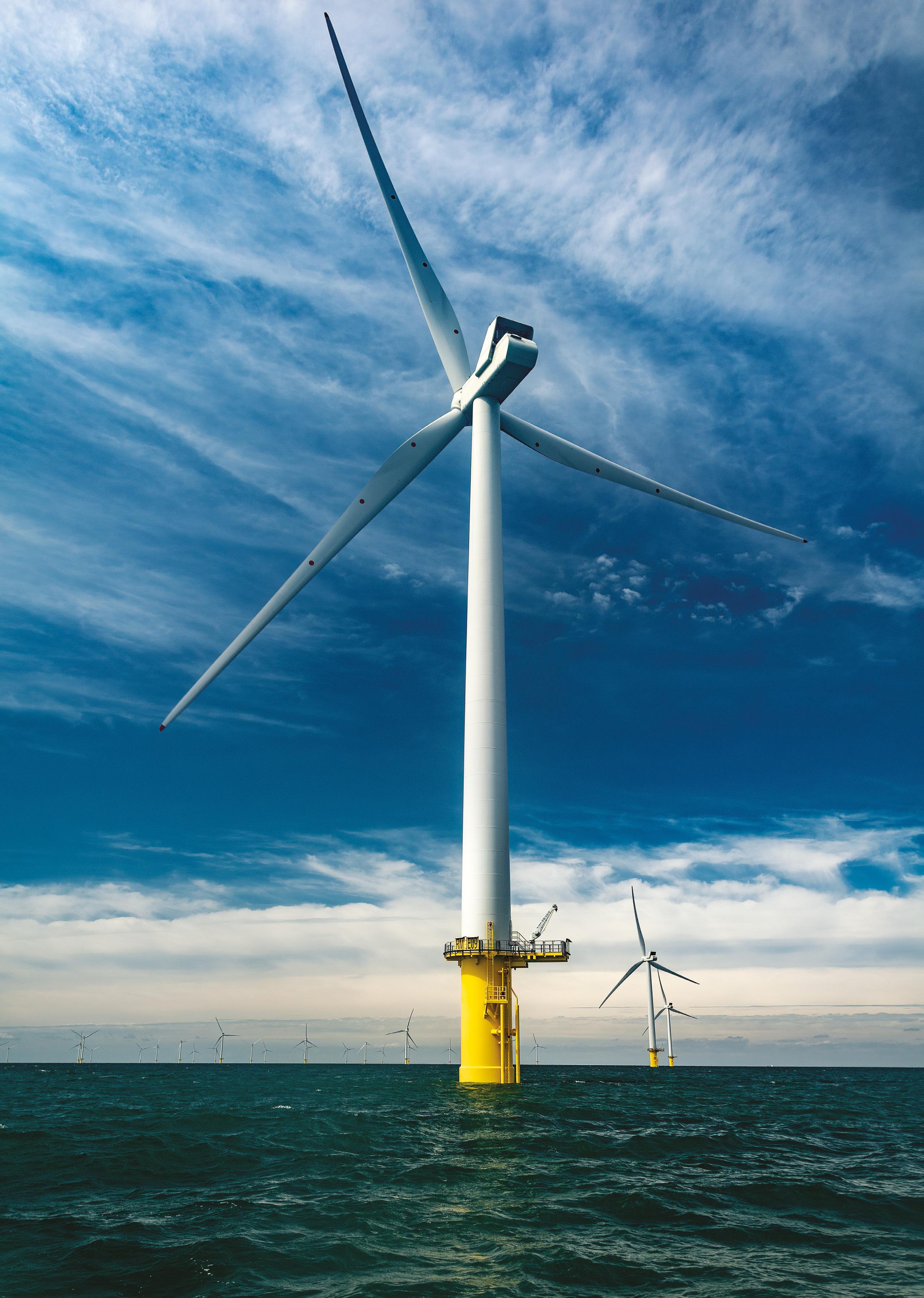
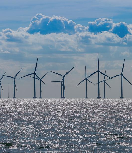
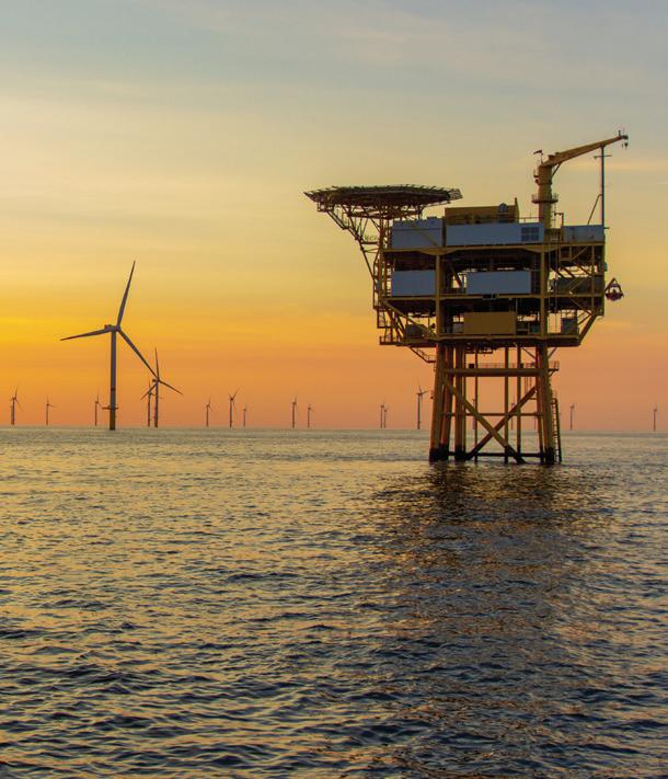
As the focus on renewable energy production continues to increase around the globe, offshore wind farms have become a key part of many countries’ strategies to produce clean, green energy. Here we explore how smart pump technology could play a vital role in this industry, and further our country’s transition to renewables.

Offshore wind farms offer many of the same benefits as land-based wind farms – they provide renewable energy, do not consume water and do not emit any environmental pollutants or greenhouse gases. However, offshore wind farms also offer many benefits that traditional land-based wind farms do not. One such benefit is that wind speeds at sea tend to be significantly faster than those on land – even relatively small increases in wind speed yield large increases in energy production, with a 24km/h wind generating twice as much energy as a 12km/h wind. Offshore wind speeds also tend to remain more steady than onshore wind speeds, enabling steady and stable generation of energy. Wind speeds on land tend to decrease into the late afternoon and early evening, which are peak times for domestic energy use. This is not the case with offshore winds, which tend to remain steady through the evening hours.
Another benefit of offshore turbines is that many countries tend to have high populations in coastal areas – Australia is a prime example of this, with more than 85 per cent of the population living within 50km of a coast. Land-based wind farms require large swathes of empty land to install and run turbines, which often means they need to be installed away from urban centres. Offshore farms can be installed at sea closer to densely populated coastal areas, enabling smooth power delivery to domestic dwellings.
Wind in the works
According to RenewEconomy, there are currently 26 offshore wind farm projects proposed across Australia, with the majority concentrated in New South Wales, Victoria and Western Australia. The process of establishing an offshore wind farm is long and complex: although every effort is made to minimise environmental impact, little is known about the long-term effects of offshore wind farms on marine flora and fauna – so ensuring strict compliance with environmental guidelines is crucial. Projects must go through multiple feasibility, evaluation and compliance stages before beginning construction. A new legal framework has further enabled development within the sector, with the Offshore Electricity Infrastructure Act being introduced in June 2022.
Thankfully, Australia can look to other countries in the world – primarily the United Kingdom, which is currently the second-largest producer of offshore wind behind China – for guidance and inspiration. As of October 2022, operational offshore wind farms in the UK totaled 2,595 turbines with a combined capacity of 13,628MW. The cost of offshore wind has historically been higher than that of onshore wind, however costs have decreased significantly and offshore wind power in Europe became price-competitive with conventional power sources in 2017.
Almost all offshore turbines currently installed around the globe are fixed foundation structures. Fixed foundation turbines are considered to be the most viable type for areas with water depths of less than 50m and average wind speeds higher than 7m/s. Floating turbines are considered technically viable with water depths from 50 to 1,000m. There are currently only three floating turbines deployed around the world.

Pumps playing their part
Pumps and pumping applications are used at many stages of offshore turbine installation, connection and maintenance. Pumps are especially vital in the installation and securing process for offshore turbines. Offshore turbines require different types of bases for stability, according to the depth of water. Types of underwater structures used to secure turbines at sea include monopile, tripod, and jacketed, with various foundations at the sea floor including monopile or multiple piles, gravity base, and caissons.
Fixed foundation turbines are generally installed using pile drivers to ensure that the foundation can be placed deeply and securely into the sea bed. The typical construction process for a monopile foundation in sand involves driving a large hollow steel pile roughly 4m in diameter and approximately 25m deep into the seabed and through a 0.5m layer of larger stone and gravel in order to minimise erosion around the pile. A transition piece is then attached to the driven pile, which generally includes features such as boat-landing equipment, cathodic protection, cable ducts for underwater cables and more. Sand and water are then pumped from the centre of the pile, to later be removed and replaced with concrete. An additional layer of even larger stone, up to 0.5m diameter, is applied to the surface of the seabed for longer-term erosion protection. Pumps used in this process are generally kinetic hydrodynamic diesel pumps and/or hydraulic pumps.
Suction caissons, or suction anchors, are another popular choice for offshore turbine anchorage. Suction caissons are a type of fixed platform anchor, featuring an open bottomed tube embedded in the sediment and sealed at the top while in use so that lifting forces generate a pressure differential that holds the caisson down. Attachment to the sea bed is achieved either through pushing or by creating a negative pressure inside the caisson skirt by pumping water out of the caisson; both techniques have the effect of securing the caisson into the sea bed. The foundation can also be rapidly removed by reversing the installation process, pumping water into the caisson to create an overpressure.
Hyping hydraulics
Wind turbines vary greatly in the ways in which they are controlled and powered. Every turbine requires some sort of internal mechanism to convert wind power into energy, as well as mechanics to transmit that energy to a generator. In order to take most advantage of the wind generated offshore, turbines need to be large enough to keep up with wind speeds that are much higher than those on land. According to the European Academy of Wind Energy (EAWE), the drivetrain of horizontal-axis wind turbines (HAWTs) generally consists of a rotor–gearbox–generator configuration in the nacelle, which enables each wind turbine to produce and deliver electrical energy independent of other wind turbines. While the HAWT is a proven concept, the turbine rotation speed decreases asymptotically and torque increases exponentially with increasing blade length and power ratings.
EAWE has presented a business case for hydraulic pump transmissions, or drivetrains, for offshore turbines. In an effort to reduce turbine weight, maintenance frequency, component complexity and thus the levelised cost of energy (LCOE) for offshore wind, hydraulic drivetrain concepts have been considered from as early as 1967. Traditionally, these concepts used oil as the hydraulic medium because of its fluidity and availability – but this presented restrictions, as a drivetrain using an oil pump would need to operate in a closed circuit in order to minimise the need for oil refreshment and avoid environmental impacts.
To overcome this, the TU Delft Wind Energy Institute (DUWIND) developed the Delft Offshore Turbine (DOT). The DOT is a hydraulic wind turbine concept that replaces conventional drivetrain components with a single seawater pump. The single water pump is powered by the turbine rotor and effectively replaces high-maintenance components in the nacelle, which in turn reduces the weight, support structure requirements and turbine maintenance frequency. Maintenance of nacelle components can be one of the most challenging aspects of offshore wind production. Turbine maintenance often requires manual work, which can be dangerous and costly.
DUWIND have also made the case for a prototype pumppowered turbine using off-the-shelf components – the DOT500. When the concept was initially developed in 2018, a low-speed high-torque seawater pump, required for the ideal DOT concept, was not commercially available. Instead, the study used a Vestas V44 600kW turbine and retrofitted its drivetrain into a 500kW hydraulic configuration. The original Vestas V44 turbine is equipped with a conventional drivetrain consisting of the main bearing, a gearbox and a 600kW three-phase asynchronous generator. The blades are pitched collectively by means of a hydraulic cylinder driven by a HPU (hydraulic power unit) with a safety pressure accumulator. The DOT500 became a fully functional hydraulic wind turbine, with fully automated and safe operation. After retrofitting the V44 drive train, a 32 per cent nacelle mass reduction was achieved. The novel spear valve torque control technology enables active regulation of the rotor speed. The total power transmission efficiency was predictably low, as a result of the double hydraulic circuit.
As a result of these tests, DUWIND is currently in development with the DOT3000 Power Train System (DOT3000 PTS) – a seawater-hydraulic drive train. The drive train, consisting of a high-torque, low-RPM, multi-MW pump, as well as a hydraulic support system, is an essential part of the innovative hydraulic multi-MW class wind turbine, which is being developed by Delft Offshore Turbine (DOT) company. The project is likely to be completed in December 2023.
Cutting-edge controllers
Another advancement in the renewable energy industry is the proliferation of smart technology. Opportunities for automation, as well as secure communication through digitalisation, are becoming more and more achievable. Offshore turbines especially benefit from automation –turbines need to be in the correct position to take most advantage of wind, and automation of positioning allows for turbines to be maximised with minimal interference or manual input.
While smart technology is already fairly commonly used in smaller-scale, onshore wind energy, offshore farms present new challenges. Firstly, turbines are unable to connect to traditional infrastructure as this doesn’t extend to deep sea ranges. There is also the challenge of ensuring electrical components are protected from the elements, as turbines can face some hefty winds and seas. Thirdly, controllers must allow for multiple components to work together to optimise turbine performance.
A wind turbine controller consists of a number of computers that continuously monitor the condition of the wind turbine and collect statistics on its operation. As the name implies, the controller also controls a large number of switches, hydraulic pumps, valves, and motors within the wind turbine. Communication between the controller and the operator has traditionally been conducted via phone, radio or fibre optics – but these types of communication can be unreliable and do not provide constant, up-to-date information on turbine performance.
Many companies are now installing wireless infrastructure as part of their turbine components, which enables turbines to be powered and controlled as part of the industrial Internet of Things (IoT). Self-optimisation can be programmed into the turbine controller, enabling the controller to assess measurement data from the turbine in order to maximise performance. Wind direction and speed can be interpreted by the controller, which can then direct turbine movement to optimal positioning by communicating with the pumps and
valves that control movement. Companies have developed such technology – using industrial wireless LAN (IWLAN), ethernet switches – to enable diagnostic functions for evaluation devices within a turbine. IWLAN in the nacelle allows network access via mobile communications.
Another big benefit of using smart controllers in turbines is the ability to instigate predictive maintenance. Predictive maintenance is a technique that uses data analysis tools and techniques to detect anomalies in operations, as well as possible defects in equipment and processes, so that they can be fixed before resulting in operational failure. Predictive maintenance of pumps is already common in many industries as pump units are frequently exposed to bearing failures, water/oil leaks and electrical faults. Machine learning can be used to assess component data and devise a predictive maintenance schedule. In the case of wind turbines, which use hydraulic and potentially seawater-powered pumps, predictive maintenance is an incredibly valuable tool in reducing reactive maintenance which results in higher downtime, higher repair cost and high safety risks.
Key takeaways
When considering the options available for offshore wind turbine components, a seawater-hydraulic drive train coupled with a wireless communication or IWLAN controller seems to present an ideal solution. The opportunity for turbine automation, predictive maintenance and wireless control, combined with the reduced LCOE and maintenance frequency of a hydraulic seawater pump, takes offshore wind turbines from a cumbersome, difficult prospect to an innovative, easyto-maintain source of renewable energy. While we are yet to see Australia’s offshore wind industry fully take shape, it may well present an exciting opportunity for the pump industry.
JOINING FORCES: THE TYPES OF PUMP COUPLINGS AND HOW THEY WORK
The primary role of a coupling is to join the rotating pump shaft to the drive shaft of the motor, which allows it to efficiently transmit power to the pump. However the right coupling in the right application can also offer plenty of advantages, including accommodating misalignment between shafts, permitting axial adjustment, vibration dampening, and absorption of shock loads. Here we look at the two main types of couplings, and explore their individual benefits.
Pump couplings can be organised into two overarching categories: rigid and flexible couplings. In general, rigid couplings are best suited to applications in which a solid connection between two shafts is desired. They can handle high precision and torque, but typically don’t offer misalignment absorption capabilities. Some common cases where you can find a rigid coupling are in vertical turbine, vertical in-line and short set pump applications. Conversely, flexible couplings are typically used in applications where compensation is needed for misalignment, movement or deflection. As the name suggests, they are much better at accommodating axial, parallel and angular misalignments and are better suited to reducing transmission of shock loads or vibration. However, they offer less torque transfer than their rigid counterparts and are less suitable for applications where precision is vital. Flexible couplings are often selected for horizontal, base plate and mounted pump applications.
Rigid couplings
Although rigid couplings are the most basic, they are also often the most cost effective and their simple structure makes for easy assembly and maintenance. The most common configuration for rigid couplings are flange, sleeve, clamp, ring, set screw and spline couplings.
Flange couplings
Flange couplings consist of two flanged hubs that are joined by a bolted pattern that allows for perfect alignment of the two hubs. This type of coupling are designed for heavy duty applications. For this reason they are often found in pressurised piping systems where two pipes need to connect.
Sleeve couplings
The simplest type of rigid coupling, sleeve couplings consist of a hollow cylindrical sleeve keyed to the shafts to be connected. These couplings are used when the two shafts are perfectly aligned, and are not recommended for high power transmission or high speeds.
Spline couplings
Like sleeve couplings, but there are slots on the inner diameter of the sleeve that correspond to the same number of slots on the shaft’s outer side. This allows them to sustain high rotational speeds and remain largely insensitive to overloading.
Clamp couplings
Used to connect shafts of the same diameter, clamp couplings are designed for quick and easy installation and removal. These couplings consist of two half cylinders that clamp on the ends of shafts and are held together by steel bolts and use just one key over the whole length.
Ring compression couplings
This coupling configuration consists of two cones that are placed on the shafts and a sleeve that fits over these cones. Three bolts are used to draw the cones towards each other and wedge them firmly between the shafts and the outer sleeve.
Set screw couplings
Set screw couplings are comprised of a cylinder that is attached to the shaft using screws that impinge upon the shaft, and often also include a keyway for keyed shafts, which gives additional capacity to transmit torque. However, they can loosen under vibration.
Flexible Couplings
Flexible couplings is an umbrella term that covers any coupling that can accommodate some degree of movement between the shafts, and can also be used for reducing vibration and noise. There are generally three categories that flexible couplings fall under: mechanically flexible, material flexible and non-contact magnetic.
Couplings that are mechanically flexible utilise parts that are designed to roll or slide against each other to compensate for misalignment. Some examples of these are grid and gear couplings
Grid couplings
Grid couplings involve two toothed hubs that are joined by a hi-tensile metal grid spring element, which transmits the torque between the two shafts. The high torque density is the main benefit of this style of coupling, and its design allows the grid to be easily changed without removing the hubs. However it has limited ability to accommodate misalignment and as it is grease lubricated it requires ongoing maintenance.
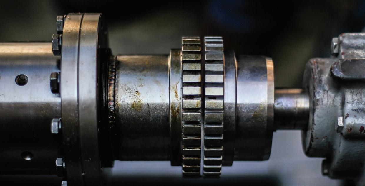
Gear couplings
A gear coupling is comprised of two metal hubs with external gear teeth that engage with teeth in the sleeve. This type of coupling can handle very high torque and has excellent misalignment capability. It is well-suited to extremely high loads and is often the coupling of choice for high torque drives.
In material flexible couplings, it’s the coupling element itself that flexes to compensate for misalignment. Some common examples are:
Jaw couplings
These couplings have intermeshing jaws on each hub that fit into an elastomeric spider that is responsible for torque transmission. This solution is relatively cost-effective thanks to its replaceable rubber elements and cast iron hubs and is disposed of and replaced rather than maintained. It is well suited for transmission of shock loads and can dampen reactionary forces and vibration.
Shear in place couplings
Similar to jaw couplings but designed so the hubs are separated. In the event of an element failure, the driving hub disengages from the driven, spinning freely to avoid motor or pump damage.
Tyre couplings
In the past these couplings were often made from rubber, which made them cumbersome and increased the axial loads on the bearing. However modern iterations utilise split urethane elements and variable spacer lengths to make this one of the most versatile economic coupling choices. These couplings are resistant to a lot of chemicals and inert to water.
Disc couplings
Disc couplings transmit torque between a driving to a driven bolt through a series of thin, stainless steel discs assembled in a pack. These couplings are all-metal and have replaceable disk packs, resulting in little to no maintenance and a strong ability to handle high torques and compensate for misalignment. Popular in the oil, gas and petrochemical industries.
Diaphragm couplings
These couplings involve two diaphragms with an intermediate member between them. They are quite versatile and can accommodate for multiple angles of misalignment and can transmit torque at high speeds without the need for lubrication. They are often found in turbines, compressors, generators and aircraft.
Non-contact magnetic couplings
Magnetic couplings use a magnet to couple the pump to the motor, which creates a small air gap between the magnet and the two components. This lack of physical contact means that misalignment and thermal expansion do not pose a problem. As there is also no mechanical seal involved this type of coupling also eliminates the risk of leakages, which is ideal for hazardous liquids. However, any particles present in the liquid it is handling can stick to the magnet. They are also not wellsuited to excessive torque, and this can cause the magnets to decouple and the pump shaft to slip.

PUMP PIONEERS: MALCOLM EYRE
Starting out
My first job out of Swinburne University was with Southern Cross Machinery, which back in the day was probably the biggest agricultural pump company. They didn't just do pumps, they did diesel engines, complete irrigation systems, all sorts. I was based in Dubbo, and we worked on the first travelling irrigators that were ever made in Australia.
I came back to Melbourne after about 18 months and began working at Industrial Engineering Limited as an Applications Engineer. I was with them until the beginning of 1974, at which time it was through them I got transferred to Germany. Industrial Engineering Limited had purchased a manufacturing licence from a German company called Rheinhütte. They are a manufacturer of chemical pumps and valves.
International education
Early in 1974, I went to Germany on the understanding that I would learn all about the product, from the manufacturing stage through to selling, the whole lot. After discussing with Industrial Engineering Limited, who was still paying my salary at that stage, I took the job on. I went to Germany thinking that the Germans were a hardworking, diligent lot. Back at that time anyway, they were what I call pigeonholed. Here in Australia, people multitask, whereas in the company I was working with over there, they were very pigeonholed.
I was there until the end of 1976, at which time I was homesick and there were a few other things going on in my life, so I came back to Australia. I went back to Industrial Engineering Limited, and I became the New South Wales Sales Manager.
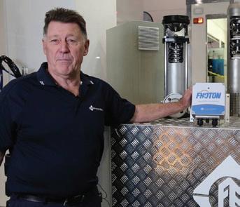
Malcolm Eyre’s incredible career in the pump industry has spanned over half a century. Currently the Managing Director of Franklin Electric Australia, Malcolm has lent his expertise to a wide range of roles and companies all over the world. Here, we take a look at his history in the pumps industry, international accomplishments and how the industry has changed over the past 50 years.
Returning to Australia
In mid-1978 I went and joined a fledgling company by the name of Kelair Pumps – who are still in business now – but at that stage they were only a very young company. After a short period with them, one of the other guys that was working at Kelair and myself decided that we could do it on our own. So we made the break and formed a company called Pump Engineers, which has nothing to do with Pump Engineers Victoria. They tried to register the same name, I think within the first 12 months of us being in business. And I said, "No, you can't have that. We already had it registered."
So off we went on our own, we were very successful in the early stages. We were successful until we took on one project that didn't go right, so we sold the company as a going concern to Envirotech, and from there I went and worked with them on a threeyear contract.
After three years, I went back to Kelair and became the Victorian and Tasmanian manager for Kelair Pumps. Then went to KSB in 1992 as the Victorian-Tasmanian Sales Manager, held that position for six years, and then became the Export Manager and National Service Manager.
I left the pump industry temporarily and took a sea change, running a stock feed business for five years. In 2007, I joined Brown Brothers. I was promoted to the position of Manager for Brown Brothers for Victoria and Tasmania and held that position until July 2015, at which time I was headhunted by Franklin Electric, and here I am. Of all the wonderful memories working in the industry, there’s been a lot of jobs along the way. But being headhunted for this role at 66 would have to be the most memorable moment of my career – it’s a pretty big move.
Variety, the spice of life
My favourite thing about working in the pump industry is that it's very varied. No two jobs are ever the same. In the pump industry, there are a number of problems that have to be solved, and I enjoy that side of it as well. Also, the people – I've met a great bunch of people through the industry, both working with them and through competitor companies.
The biggest change that's taken place in my time is the introduction of variable speed drives (VSDs). When I came back into the pump industry after an absence of five years, and these VSDs had come into play in a large way, I'd never really bothered to pick it up. I thought, there'll
be younger guys that are computer savvy and have this tech that I didn't have. So I've relied on others to do that side of the business. That change put me a bit on the back foot, because being elderly…I use the old cliche: you can't teach an old dog new tricks.
Memorable mentors
In my early days at Industrial Engineering Limited, I had a mentor by the name of Alan Scott. He was the National Sales Manager, and Scotty was a very personable person and pointed me in the direction that we are in a people business. That's been my philosophy pretty much all the time, but I picked that up from Alan.
Another personality I worked with was Bill Smith, who was one of the part owners of Kelair Pumps. Bill, I'd put him down as a mentor as well. Bill and I had a really good relationship. The Managing Director of KSB, a German guy who was in fact the managing director when KSB employed me, his name was Peter. And, again, Peter was a good influence.
Industry evolution
Something that's changed dramatically since I started was that when I started, just about every pump that was sold in Australia was made in Australia. Now, I don't think there's anybody making pumps completely in Australia. I think Davey Pumps may make some of their products, but I don't know that they make the whole product. That's the biggest change, the fact we've gone from a country that used to make pumps of every shape and size and now we make nothing.
Another thing is that now everybody that makes a pump somewhere in the world is trying to sell it in Australia. The pump market pie has shrunk, but the number of players in it has grown. So it's been, in that respect, a tough business. It's not a complicated business. I think I'm getting out of the business at the right time. At 75, I've had enough. It's been a great industry to me, I've had a pretty good life out of it, I've met a lot of great people, and that's about it.
Surmountable challenges
I think the pump industry's got a bright future in Australia. Our two biggest export commodities are mining and agriculture, and in both those fields, pumps play a pretty big part. Unfortunately, there's no research and development done in Australia. And that, I believe, was one of the downfalls, along with the fact that our market is so small. And the other challenge, what goes hand in glove with that, is our labour costs. That's one of the other reasons why manufacturing disappeared here.
After the pump industry
In my spare time I do a bit of walking. I am a very keen Richmond supporter, and just go to the football most weekends if I'm not going somewhere. I tend to go away a bit, I have two sons, one lives in Sydney, the other one lives in Canberra, so I go and see them quite regularly. And come the 15th of September when I retire, I've got a caravan ready and I'm going on a never-ending trip around Australia.

Understanding pump curves #10: when best efficiency isn’t best
By Ron Astall, United Pumps AustraliaLong-time readers of Pump Industry will be familiar with Ron Astall’s popular series of articles on understanding pump curves. In this installment, Ron is back to explain how to select centrifugal pumps for very low flow.
If anyone can remember my previous dissertations; Understanding pump curves #5 and #6 you will recall our exhortations to select centrifugal pumps to operate as close as possible to their best efficiency point (BEP). Indeed, this is enshrined in most pump engineering standards. The American Petroleum Institute standard API 610 has a strong preference for pumps to be selected to operate between 80 per cent and 110 per cent of BEP and most other specifications echo a similar requirement.
I am going to suggest; possibly controversially; that this is not always the best approach for efficiency and power consumption. I propose that in some circumstances we ignore the accepted wisdom. For an engineer this can be scary! A variation on an old children’s joke illustrates this; “Why did the engineer cross the road? They looked in the file and that’s what they did last time”.
A senior machinery engineer once bluntly warned me about blindly following a specification; saying that “a specification is the first refuge of the incompetent”. Having now possibly insulted many of you, let us review the generally accepted wisdom.
It is best practice to select and operate pumps close to their BEP
Generally, this is absolutely true. Why do we want to operate pumps close to BEP?
Consider this example from the PIA pump handbook (Figure 1):
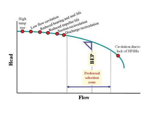
To recap, Figure 1 is generalised but provides a convenient overview of the scary symptoms associated operation well away from BEP with issues such as:
• Increased internal turbulence
• Recirculation
• Increased pressure fluctuations
• Increased vibration due to the above
• Increased axial thrust – depending on pump hydraulic balance method
• Increased radial thrust; particularly with single volute casings
• Temperature rise due to high internal energy loss High radial (side loading) on the shaft is a real problem when pumps are operated at low flows. Premature bearing failure is a risk, along with shaft breakage. In Figure 2, I have added the radial loading. The red and the blue lines show how the radial load varies with operating point for both a single volute casing and a double volute casing respectively:

So, what are the circumstances where we might place less importance on this sage advice? The answer is when we have very low flow duty points. This is all about the parameter Specific speed (Ns).
Specific speed:
This was discussed in Understanding pump curves #7 –are your pumps running too slowly? The parameter Specific Speed (Ns) relates to impeller shape, which influences pump efficiency. Specific Speed is calculated at the BEP of a pump, as shown in Figure 3.
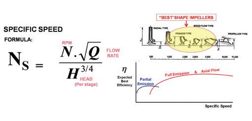
From the Ns formula, the mathematicians amongst us will see that for a given RPM and head, a low BEP flow rate will give us a low Ns, and a narrow impeller. Narrow impeller passages are inherently less efficient than the more open passages of higher Ns impellers.
What can happen is that a small pump selected at BEP for a low flow rate service may have a lower operating efficiency than a larger pump running back on its curve.
Figure 4 shows just one example of two pumps selected for the same duty.

The pump ‘B’ selection looks ugly. Pump ‘A’ is running close to BEP and gives us a warm fuzzy feeling. It should be a smooth, reliable pump. And it will be.
But, pump ‘B’ is more than eleven percentage points more efficient than pump ‘A’ and will use 33 per cent less power
(5.6kW less). In continuous operation that will be 49,056 fewer kilowatt-hours per annum, and at 15c per kilowatt-hour, that equals $7,358.00 a year of cost savings. This is not an unusual example.
The purists and devotees of the accepted wisdom will prefer Pump ‘A’. Those striving for power savings will prefer pump ‘B’.
Can a pump running back on its curve be reliable?
Yes it can. Typically the minimum Continuous Stable Flow (MCSF) quoted by experienced manufacturers will be around 25 per cent to 35 per cent of BEP flow. A selection in this region and above is not necessarily a reliability trap if it is done for efficiency reasons.
The purists and the devotees of rigid specifications may howl, but yes, a properly engineered pump can be designed for the radial loads and the bearing life. Modern shaft design can provide sufficient rigidity for reliability and mechanical seal life. The important question is the total cost of ownership. No one wants to trade away reliability for a better efficiency, if the trade means higher maintenance costs and unplanned outages.
How do we ensure reliability?
Casing design:
• If we look back at Figure 2, it is obvious that a double volute pump will have a much lower radial loading on the shaft and bearings. Go for a double volute or a multiple volute (diffuser) casing if available. This will reduce the radial loads at partial capacity.
• In smaller pumps, sometimes circular single “volute” casings are used to reduce side loads at partial capacity. With a circular casing, the side loading typically increases with flow and is reduced at partial capacity.
Rugged bearing frames:
• Yes, every pump brochure says the design of their bearing frame is rugged. But some are more rugged than others.
• Pump manufacturers have various standard bearing frames in their range; each of which will support a number of hydraulic sizes (wet ends). Each bearing frame is designed to handle the largest wet end in its group. If your selected pump is not the largest on that frame size, then it is overdesigned. That’s good news.
• Use an accepted design standard that stipulates bearing life and shaft deflection criteria such as ANSI B73.1, ISO 5199 or – if you are really serious – API 610.
Summary
I am not suggesting that it is better to run a particular pump back on its curve than at BEP. We like to select our pumps to run at BEP. However, for very low flow rates, chasing pumps with a BEP to match the duty may not give us the best selection.
What I am proposing is that sometimes, the best pump selection may not be the one that follows the accepted rules. Be prepared to bend the rules when your analysis shows you a better way. You may end up with a slightly larger pump that has better efficiency, lower power costs; and with attention to design it can be as reliable.

The pump industry relies on expertise from a large and varied range of specialists, from experts in particular pump types to those with an intimate understanding of pump reliability; and from researchers who delve into the particulars of pump curves to experts in pump efficiency. To draw upon the wealth of expert knowledge the Australian pump industry has to offer, Pump Industry has established a panel of experts to answer all your pumping questions.
As energy costs remain high around the world, increasing the operational efficiency of wastewater treatment plants (WWTPs) continues to be of great importance. One process that is often overlooked is the transport of dewatered sludge to silos, containers or other storage locations. This edition of Ask an Expert looks at a combination of progressive cavity pumping and dense phase pneumatic conveying called Smart Air Injection (SAI). This cutting-edge technology improves process efficiency and significantly reduces energy consumption, investment and lifecycle costs, resulting in an unprecedented reduction in total cost of ownership.
Q. What are the challenges of transporting dewatered sludge over long distances?
A. Highly viscous media, such as dewatered sewage sludge, are difficult to pump over long distances due to their weak flow characteristics. Poor flowability causes significant pressure loss in the pipeline, which can only be overcome by using sequential pumping solutions such as belt and screw conveyors with multiple drive units. These multiple drive units require a large amount of energy and maintenance, resulting in higher energy and maintenance costs. Large high-powered pumping solutions could also be used to transport dewatered sludge (i.e. piston diaphragm or multi-stage progressive cavity pumps) but again, as with belt and screw conveyors, both energy and maintenance costs are much higher with these alternatives.
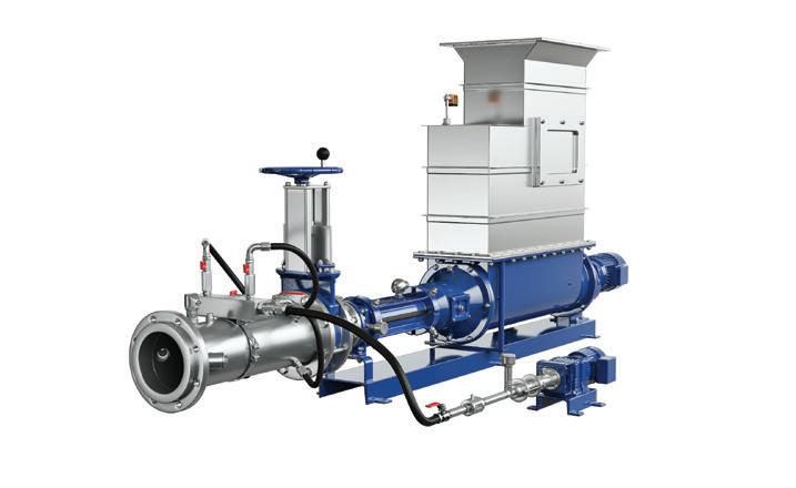
For dewatered sludge transport, the SAI system offers unprecedentedly low energy consumption and reduced total cost of ownership.
Q. What is so special about this new pumping solution?
A. Smart Air Injection (SAI) pumps viscous media with variable dry solids content over long distances. It is a customised solution that uses a combination of progressive cavity pumping and dense phase pneumatic conveying to transport highly dewatered sludge discontinuously in short plugs, unlike any other conventional conveying technology. As a result, friction losses occur only along these plugs and not in the entire pipe, resulting in numerous unique advantages, such as the ability to transport up to 1km with a low-pressure pump and PN10 piping.
Q. How does this technology work?
A. With SAI, the sludge is first compacted by an open hopper pump in the pressure pipe and then conveyed
by pulsed compressed air injections, similar to a pneumatic post system. The timing of the air injection is determined by an algorithm optimised for the SAI application based on the discharge pressure level. In addition, the sludge plug is coated with a lubricant solution to reduce pipe friction for dense phase conveying, thereby increasing the energy efficiency of the entire system. Overall, very little compressed air is required for pumping.
Q. Our WWTP is a complex network of machinery and piping. Do I have to build everything from scratch?
A. No, the existing old piping can still be used, although the new system does not require high-pressure piping and valves. The good news is that the solution is extremely flexible. This means that distances of up to 1km with
changes in direction and elevation are no problem. In the case of rebuilds, SAI systems can also be adapted to new plant layouts.
Q. What are the greatest advantages of this pump system?
A. This state-of-the-art technology can significantly reduce operating costs by up to 72 per cent for energy and 88 per cent for maintenance. Reduced discharge pressure extends the life of all conveying components. Investment costs are reduced by up to 90 per cent through the use of thin-walled piping and valves (PN10). As a customised pumping solution, it is designed to meet the needs of the plant and is parametrised on site to optimise energy consumption. It is also remarkably economical, as the total investment and follow-up costs are comparatively low.
Peter Vila, Managing Director of SEEPEX Australia, is a progressive cavity pump expert. He has been involved with pumps for over 40 years. Peter spent the first five years repairing pumps and the following 35 years in technical sales, 20 of which have been with SEEPEX progressive cavity pumps.
For more information on progressive cavity pumps, please contact SEEPEX Australia on (02) 4355 4500 or at info.au@seepex.com

Leading fluid path solutions provider expands Australian presence with new Perth office
Watson-Marlow Fluid Technology Solutions (WMFTS) is celebrating the opening of its new Perth office, the company’s second in Australia.
Previously operating solely out of its Sydney office, WMFTS has been a leading provider of fluid path solutions for the past 13 years. This new Perth office brings the Watson-Marlow team closer to its Western Australia-based customers so that it can further enhance its quality of service.

This new Perth base is located in Belmont, and is focused on directly supporting, selling, servicing and repairing WMFTS solutions.
Elie Elazar, Country Manager at Watson-Marlow Australia, said, “We’re delighted to strengthen our presence in the market with the opening of our second office in Perth. We put the customer at the heart of everything we do and with our Perth site, we are making sure that we can truly partner with them on their fluid path challenges.”
INTAKE DESIGN – PART 2
The PIA’s Australian Pump Technical Handbook is a cornerstone text for the Australian pump industry and, in our opinion, a must have for anyone who deals with pumps on a regular basis. In this ongoing series, we feature abridged chapters from the classic book to showcase the various areas covered and to reacquaint readers with the technical aspects of pumps. Here, we continue our investigation into intake design.
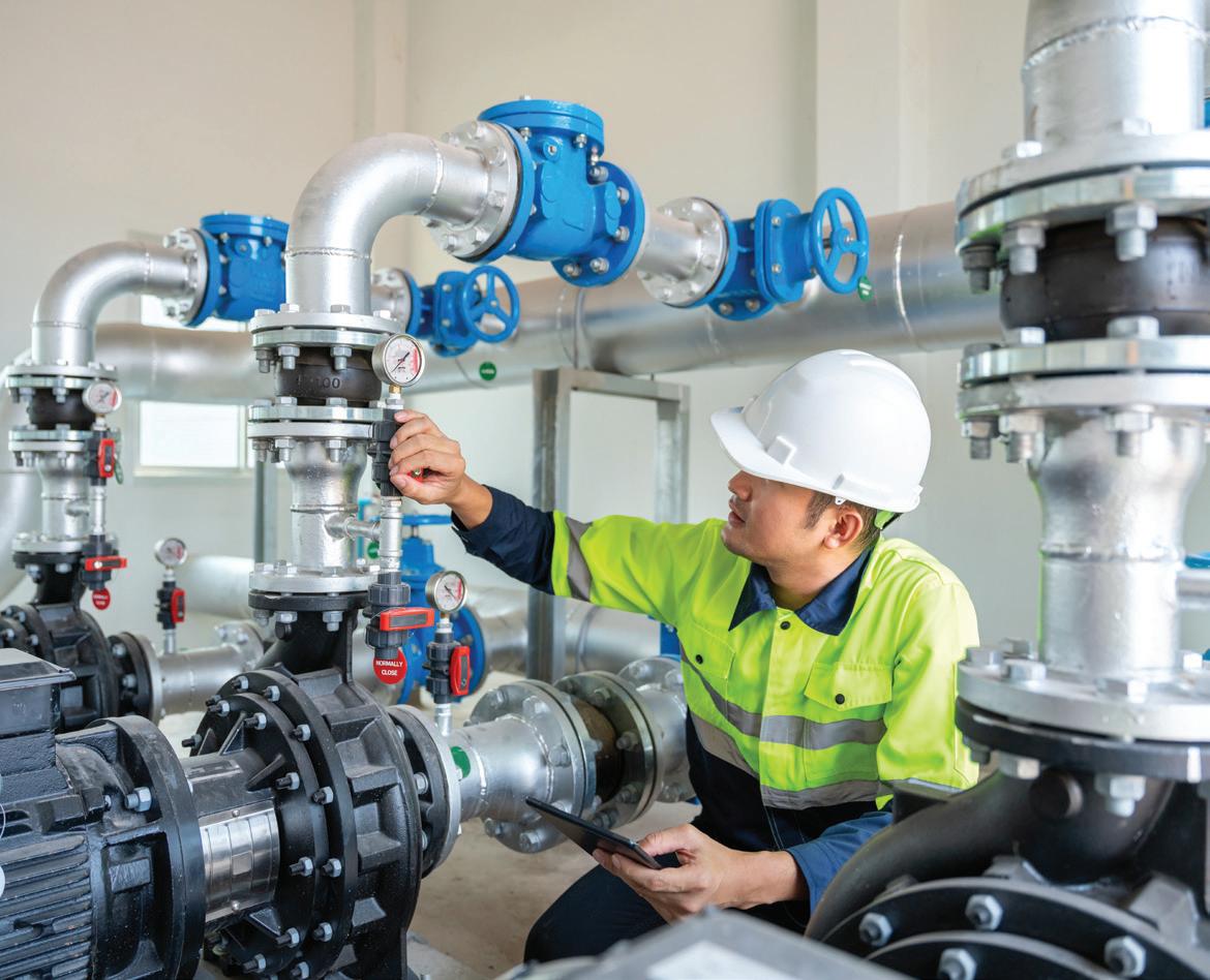
In part two of this section on intake design we cover how to calculate the volume of a sump, in order to ensure that the pumps in the sump operate satisfactorily without any of the problems outlined in the previous article.
Optimum sump volumes
During the start-up of an electric motor, higher than normal operating currents are drawn from the power supply. This causes a transient disturbance in the supply, which results in a voltage dip, and produces significant heat energy in the motor. These effects put a limit on the maximum number of starts for a motor in a given time, and therefore on the minimum sump volume. This should be considered when deciding sump dimensions for optimum flow conditions.
Factors to consider include:
• Inlet flow to the sump
• Sump retention time
• Number of pumps required
• Discharge capacity of each pump
• Operating level of each pump
• Desirability of fixed or variable speed pumps
• Minimum cycle time for each pump
If variable speed pumps are used, the number of starts per hour ceases to be of significance and the minimum sump volume is governed by the control system for varying the pump speed. The water level can normally be held to within 500mm of a set point for this type of control.
Minimum sump volume for a one-pump system (fixed speed pump)
The minimum volume is defined by the highest start level and the lowest stop level in the sump and is given by the formula:
Where: V = The minimum sump volume
Qi = Inlet flow to the sump in litres/sec
S max = Motor maximum allowable starts per hour
Q a = Average pump flow between start and stop levels, i.e.:
Q a = (Q1+Q2)
2
Where:
Q1 = Pump flow at pump start level n litres/sec Q2 = Pump flow at pump stop level in litres/sec
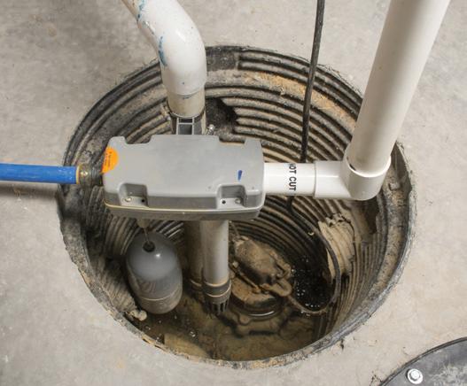
The minimum size of the pump sump is determined by the allowable numbers of starts per hour, Smax, of the pump driver. The number of allowable starts per hour is normally a function of motor design and this information is provided by the motor manufacturer.
The above formula can be used when the inflow is constant, and the pump flows are known. If a sump is being designed from scratch, then assumptions need to be made. Safe assumptions are to design the pump flow to be twice the maximum inflow. This minimum volume is calculated from:
In reality the inflow is rarely constant and will differ according to the time of day, the weather, etc. This formula will provide a calculated sump volume that is over specified for periods where the pump is inactive, i.e. during dry weather and night flows. However, it will ensure that the sump does not overflow.
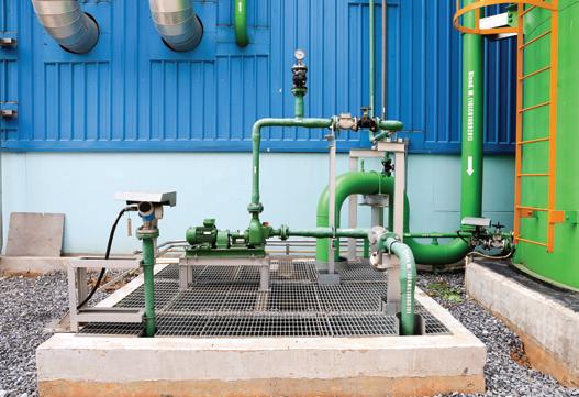
Minimum sump volume for multi-pump system (fixed speed pumps)
The volume calculated using previous equation for a single pump can be used as the base for a multi-pump system with additional volume needed to be allowed for each additional pump in the system.
What this volume is, depends on a number of factors, including the start/stop sequence of the various pumps, the minimum allowable pump cycle time, the capacity of each pump in the system, how the inflow to the sump varies and if pumping sewage the possibility of it turning septic from too long in the pump sump. We recommend that this calculation be done on an individual basis by a professional engineer with experience in multi-pump system design.
In the case of a two pump system in which one of the pumps is a standby unit, the start level for the standby pump should be a minimum of 150mm above that of the working pump, this ensures that the standby pump will not accidentally start.
Summary
It is important that pump sumps are sized correctly to avoid the problems discussed in part one of this article. Model testing should be conducted to ensure that the size of pumps proposed will work properly in the sump, and wherever else it is necessary, and to confirm that the pumps and sumps will operate effectively.
PUMP SCHOOL

WHAT IS AN INTERNAL GEAR PUMP AND HOW DOES IT WORK?
An internal gear pump is a type of positive displacement pump, characterised by an external gear (driving gear) and an internal gear (driven gear) with internal teeth. The external gear drives the internal gear, meshing together inside the casing, causing fluid to be trapped and transported from the pump's inlet to the outlet.
The choice between gear pumps and other pump types depends on several factors, including the specific application requirements, fluid properties, flow rates and pressures. It's important to evaluate these factors and consult with a pump expert to determine the most suitable pump type for a particular application.
Take the following example of a Viking positive displacement pump, which clearly demonstrates how it works.
Viking’s simple “gear-within-a-gear” principle has only two moving parts. The first part is the positive displacement of the liquid that is accomplished by filling all the spaces completely between the teeth of the rotor and idler gears.
With every revolution of the pump shaft, a certain amount of the liquid enters the pump through the suction port. The liquid then goes on to fill the spaces between the teeth of the rotor and the idler. The crescent on the pump head then separates the flow of the liquid as it effortlessly moves toward the discharge port.
The idler gear, which carries the liquid between its teeth and the inside surface of the crescent, is then rotated on the pin, which is supported by the pump head.
The rotor gear transports the liquid between its teeth, which travels between the casing and the outside surface of the crescent that is connected to the pump shaft. The four diagram drawings illustrated show how a positive displacement pump works.


The missing link in your B2B Marketing Strategy
While traditional trade publications have quality audiences and high levels of trust, they can lack the full range of services to guarantee a return on your investment. And while traditional marketing agencies offer the latest marketing techniques, they don’t have the audience or the industry understanding the B2B sector needs.
Monkey Media is the missing link that brings together a trusted brand and powerful audience, with a complete agency offering.
TO FIND OUT MORE SCAN THE QR CODE NOW
EDITORIAL SCHEDULE & ADVERTISERS INDEX
The ifm moneo platform goes beyond monitoring and detection, it gives you full visibility and control over your assets allowing you to perform maintenance at optimal times.
The ifm moneo platform goes beyond monitoring and detection, it gives you full visibility and control over your assets allowing you to perform maintenance at optimal times.

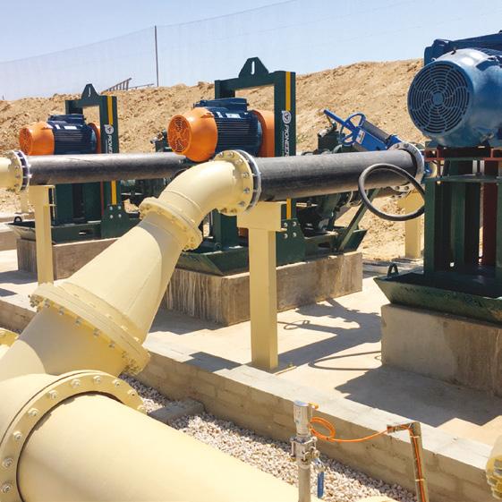

You don’t need a data scientist or analytics expert to know the condition of your machinery.
You don’t need a data scientist or analytics expert to know the condition of your machinery.
A self-service tool that enables successful predictive maintenance programs through the help of artificial intelligence methods.
A self-service tool that enables predictive maintenance programs through the help of artificial intelligence methods.
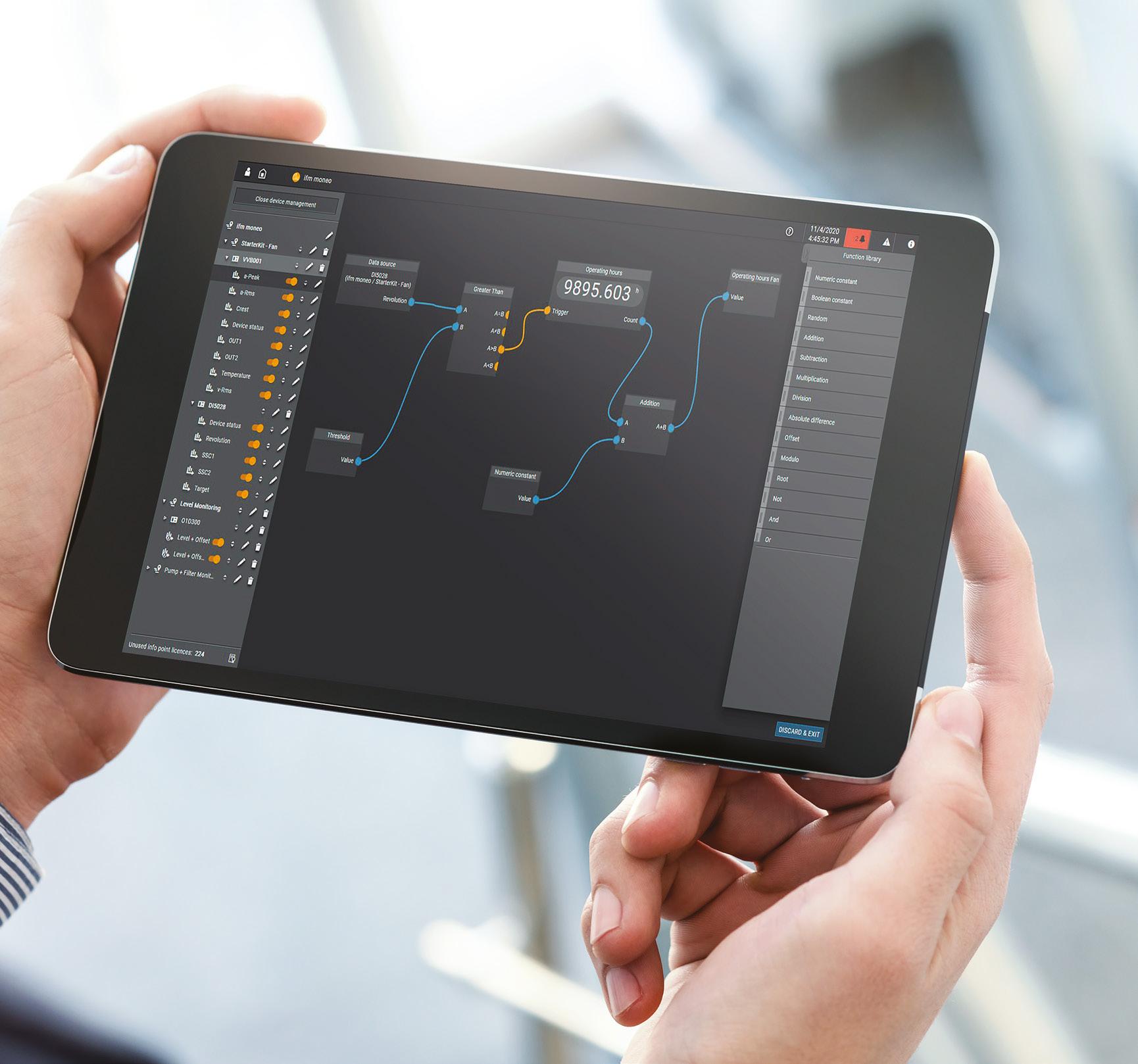


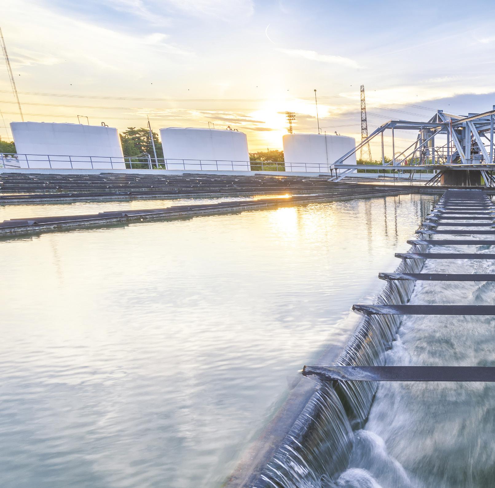


Pump stations and submersible pumps face many challenges causing unplanned breakdowns. The moneo solution can detect the following issues:
Pump stations and submersible pumps face many challenges causing unplanned breakdowns. The moneo solution can detect the following issues:
n Predictive monitoring of bearings, gears and electric motors
n Predictive monitoring of bearings, gears and electric motors
n Rotating pump parts
n Rotating pump parts
n Pumps rotor and valves
n Pumps rotor and valves
n Water pressure, temperature and flow rate at the pumps outlets
n Water pressure, temperature and flow rate at the pumps outlets
n Faulty or damaged bearings
n Faulty or damaged bearings
n Faulty or damaged seals
n Faulty or damaged seals
n Wear issues and rub issues
n Wear issues and rub issues
n Imbalance
n Imbalance
n Cavitation
n Cavitation
n Looseness
n Looseness
n Unusually high signatures in grinders and macerators
n Unusually high signatures in grinders and macerators
