pumpindustry

Everything you need to know about valves State of the Industry: changes ahead for 2016
The dos and don’ts of pumping fuel oil
SUMMER 2016 ISSUE 14
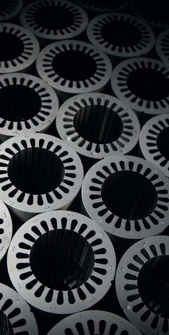

HIGH QUALITY MOTORS ON DEMAND ON BUDGET QUALITY. SERVICE. RANGE. LOW VOLTAGE MOTORS 0.06kW to 1400kW SINGLE PHASE 0.09kW to 3.7kW HIGH VOLTAGE 355kW to 10 MW www.techtop.com.au info@techtop.com.au Melbourne: 03 9753 2222 Brisbane: 07 3106 5111


Pump Industry Australia Incorporated
Kevin Wilson – Secretary PO Box 55, Stuarts Point NSW 2441 Australia
Ph/Fax: (02) 6569 0160 pumpsaustralia@bigpond.com
Ron Astall – President United Pumps Australia & Astech Consulting Services
John Inkster – Vice President Brown Brothers Engineers
Keith Sanders – Councillor Australian Industrial Marketing & Life Member
Alan Rowan – Councillor Life Member
Frankie Camilleri – Councillor John Crane
Ashley White – Councillor Davey Products
David Alexander – Councillor KSB Australia
David Brooks – Councillor Flowserve Australia
President’s welcome
Welcome to a new year, and a new issue of Pump Industry.
2015 was a busy year, building on the hard work from 2014, with the essential input of PIA secretary Kevin Wilson and our three part time Executive Officers, Keith Sanders (Marketing and Statistics), Alan Rowan (Publications and Training) and Ken Kugler (Standards). Thanks to these gentlemen for an excellent and productive year.
As in 2014, the common themes were education and improvement. PIA’s vision is to continue our focus on education and training with ongoing seminars, conferences and workshops.
Our cooperation with Chris Bland, Laura Harvey and Aaron White of Monkey Media is highly valued and we continue to receive positive comments from pump users on the relevance and quality of this Australian publishing initiative.
When visiting a customer in New Zealand last November I was surprised to see a copy of Pump Industry on his desk. We agreed that there were too many photos of me in the magazine, but he remarked that he considered it to be a great read and that he always looks forward to the next issue.
You can read elsewhere in this issue more detail on some of our key achievements during 2015, including our new relationship with the Hydraulic Institute; but one achievement that I particularly want to highlight is the
roll out of the PIA’s Installation and Commissioning Training Program. Congratulations go to Alan Rowan and his team of Ken Kugler, Keith Sanders and Fred Van Ross. I know it has been a hard slog and that the workload will continue with ongoing refinements and improvements. Well done!
You can also read about John Link being awarded PIA life membership. It was a particular pleasure for me to be able to officiate at this time. His generous approach to life and work continues to be an inspiration.
John’s role in assisting with our Installation and Commissioning Training Program is consistent with his ideal of an educated and competent industry, an industry where sound engineering, ethics and a level playing field prevail.
While I have used this before, I think it is appropriate to again mention a quotation from Astronaut John Glenn Junior – the first American to orbit the earth, a US senator and later the oldest ever Astronaut when he flew again in the Space Shuttle.
“As I hurtled through space, one thought kept crossing my mind - every part of this rocket was supplied by the lowest bidder.“
An educated and competent industry is important if we are going to rely on the ‘lowest bidder’.
Ron Astall President, Pump Industry Australia
www.pumpindustry.com.au pump industry | Summer 2016 | Issue 14 1 PUMP INDUSTRY


3,345

Editor’s welcome
Welcome to the first edition of Pump Industry for 2016.
by Monkey Media Enterprises
ABN: 36 426 734 954
PO Box 3121
Ivanhoe North VIC 3079
P: (03) 9440 5721
F: (03) 8456 6720
monkeymedia.com.au
info@monkeymedia.com.au
pumpindustry.com.au
magazine@pumpindustry.com.au
Publisher and Editor: Chris Bland
Managing Editor: Laura Harvey
Marketing Director: Amanda Kennedy
Marketing Consultant: Aaron White
Marketing Consultant: Jordan Harbinson
Associate Editor: Michelle Goldsmith
Associate Editor: Emily Thomas
Journalist: Jessica Dickers
Designer: Alejandro Molano
Creative Director: Sandy Noke
ISSN: 2201-0270
It has become somewhat of a tradition that in the first issue for the year, we bring you an overview of how the industry has performed over the previous year, and what’s in store for the year ahead.
This year, we’ve conducted our most comprehensive survey yet, speaking to countless pump industry professionals to gain their insights into the challenges they’re facing and the successes they’ve had.
Overall we found our respondents to be feeling positive about what lies ahead; while there’s no denying that 2015 has been one of the most difficult years our industry has faced, our respondents feel that the tide is starting to turn and that the year ahead will be better than the year gone. Sectors experiencing growth, including water and wastewater, and domestic
This magazine is published by Monkey Media in cooperation with the Pump
not necessarily the views of either the publisher or the PIA. Neither the
advertisers.
All communication should be directed to the publisher.
The publisher welcomes contributions to the magazine. All contributions
providing content to the publisher, you authorise the publisher
with other content in any of its publications and in any format at the publisher's
and commercial construction, will provide benefits to the industry; and the increasing need for energy efficient products and the service of existing equipment are also expected to keep the industry busy.
The full results of the survey and our analysis of your responses make for compelling reading – turn to page 30 for the full story.
The start of 2016 also marks the start of an exciting new period for the PIA. Last November I attended the PIA’s Annual General Meeting, where I had the chance to learn a bit more about some of the new initiatives the PIA has underway. These include a fully revamped website, and a new partnership with the US Hydraulic Institute, which will lead to increased knowledge sharing – a clear benefit for all PIA members.
Chris Bland Publisher and Editor
2
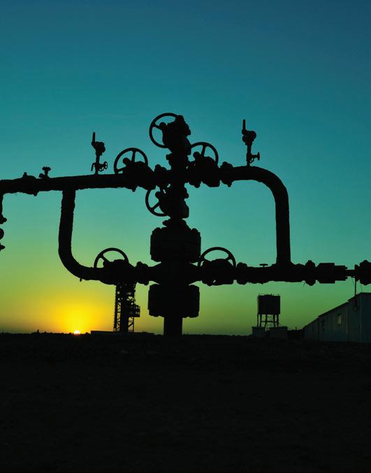
Cover image highlights our feature on pumping in the oil and gas industry.
Published
Industry Australia Inc. (PIA). The views contained herein are
publisher nor the PIA takes responsibility for any claims made by
comply with the publisher’s editorial policy which follows. By
to reproduce that content either in its original form, or edited, or combined
discretion.
must
SUMMER 2016 ISSUE 14 Everything you need to know about valves State of the Industry: changes ahead for 2016 The dos and don’ts of pumping fuel oil
pumpindustry
Authorised Australian Distributor for

Head Office: 88 Wedgewood Road, Hallam VIC 3803, Australia Phone: (03) 9796 5001 Fax: (03) 9796 3499
SOLID HANDLING PUMPS & MIXERS FOR PROCESS INDUSTRIES
RECESSED IMPELLER RECESSED IMPELLER
SCREW CENTRIFUGAL SCREW CENTRIFUGAL
CHOPPER PUMP CHOPPER PUMP
VERTICAL BEARING VERTICAL BEARING

SUBMERSIBLE SCREW CENTRIFUGAL SUBMERSIBLE SCREW CENTRIFUGAL
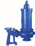
Large internal passages for handling solids up to 200 mm
Replaceable wear element, extra-thick castings and hard metal construction for abrasion resistance.
Foot mounted casing provides true back pull-out.
Available in horizontal, vertical dry pit, vertical bearing, vertical cantilever and submersible designs.
Gentle, low shear pumping action minimizes product damage and prevents emulsification.
Single channel open impeller for solids up to 178 mm diameter
High efficiency reduces power costs.
High flow/low head hydraulic characteristics.
Low NPSH.
Available in horizontal, vertical dry pit & submersible designs
Simultaneously chops and pumps solids. Eliminates the need for grinders.
External and internal cutting actions.
Patented high efficiency, anti-fouling impeller.
Available in horizontal, vertical dry pit, vertical bearing, vertical cantilever and submersible designs.
Economical solution for general duty in industrial sumps
Reliable self-priming independent of pit depth.
Optional sealed columns for harsh environments. Standard designs for pit depths up to 14 feet, custom versions to 20 feet+.
Recessed impeller, chopper and process pump wet-ends available.
For submerged operation in tanks or sumps. Chopper, recessed impeller, and screw centrifugal designs available.
Capacities up to 910 m3/hr
Heads up to 61 metres
Temperatures up to 150°C
Solids up to 200 mm diameter
Capacities up to 2730 m3/hr
Heads up to 60 m
Temperatures up to 150°C
Solids up to 178 mm diameter
Capacities up to 1408.4 m3/hr
Heads up to 39.624 m
Temperatures up to 150°C
Capacities to 681.36 m3/hr
Heads to 91.4 metres
Temperatures up to 204°C with jacketing
Capacities up to 2730 m3/hr
Heads up to 60 m
Temperatures to 110°C
152 mm diameter maximum solids size
ST SERIES TOP ENTRY MIXERS
ST SERIES TOP ENTRY MIXERS


Three drive sizes cover this series which feature a third lower output bearing which helps isolate hydraulic loads from the gearbox.
2.24 to 14.91 kW
Typical mixing volume: 18.93 to 132.49 m3
service@pumpdoctor.com.au s a les@ p um p d oc t o r. c o m.au www.pumpdoctor.com.au
> > >
> > > > > >
> > > > > > > >
> > > > > > > >
> > > > > > > > > >
> > > > > > > >
Head Office: 5 Brigden Gate, Halton Hills, Ontario L7G 0A3 Canada. Phone: (905) 693-8595 Fax: (905) 693-1452 For more information visit www.haywardgordon.com



STATE OF THE INDUSTRY
Recently Pump Industry undertook the most comprehensive survey we’ve ever conducted in order to present a detailed analysis of the industry’s outlook for 2016.
To add another perspective to our State of the Industry analysis, we spoke to Ivan Fernandez, the Industry Director at Frost & Sullivan’s Industry practice in Sydney.
PUMP SYSTEMS
at the total piping system
In the first of a regular series of columns on overall piping systems, Ray Hardee discusses how the various elements making up a total pumped system work together to meet system requirement.
OIL & GAS
ASK AN EXPERT
4 pump industry | Summer 2016 | Issue 14 www.pumpindustry.com.au
State of the Industry in 2016: adapt, diversify, survive 30
Analyst weighs in ...................................................... 38
Looking
.......................... 40
The dos and don’ts of pumping fuel oil ................... 42 Getting out of hot water 45
Progressive cavity pumps ........................................ 46 CONTENTS PIA NEWS The new face of the PIA ...........12 PIA MEMBER NEWS Sulzer launches new process pump range ..............................16 New centrifugal pump range by Gorman-Rupp .....................17 Operating pumps at partial capacity: causes of vibration ...18 INDUSTRY NEWS Produced water treatment 20 Improved safety in explosive atmospheres ...........................22 Drive solutions for the water world.............................................. 23 From humble beginnings to dramatic expansion..................24 Efficiency and flow monitoring ................................26 Not to be sniffed at 27 Optimised water solutions ......28


REGULARS
considerations by industry
are vital components of pumping systems and pipelines in near-countless different industries.
This article presents some conventional and innovative ways to apply check valves in hydraulic circuits. The author has successfully used all the configurations in various projects.
A beginner’s guide to the right actuator
A valve, in its most basic form, consists of a body and an internal moving component (closure element), which shuts off or restricts flow through the valve.
REPAIR AND
and tricks for maintaining your
you following maintenance best practices?
to know your pump system:
speed and system head
caught up with Bob Pullen to reflect on his years as a pioneer of the Australian pump industry.
www.pumpindustry.com.au pump industry | Summer 2016 | Issue 14 5 pumpindustry VALVES Selecting valves:
and application ......................................................... 48 Valves
Check valve applications 52
................. 56
MAINTENANCE Tips
AODD pump ............................................................. 60 Are
.... 63 TECHNICAL Getting
specific
67
President’s welcome ................... 1 Editor’s welcome ......................... 2 News ............................................ 6 Pump pioneers .......................... 68 We
Pump school .............................. 71 Which pump do I choose? Editorial schedule ...................... 72 Advertisers’ index ..................... 72
Pumpserv appoints new sales representative
Ross Shaylor has recently joined the team at Pumpserv as their new Sales Representative. Ross has a long history in industrial sales and started in the pump industry in 2010, initially working for Ebara Pumps as NSW Area Manager before moving to Brown Brothers Engineers. Ross has a proven track record of developing and maintaining positive relationships with key stakeholders. Continually looking for opportunities to expand his knowledge and understanding of pumping and industrial applications, Pumpserv is an ideal business for Ross to expand his knowledge base.
Pumpserv is a distributor of all major pump brands in Australia, and offers everything from design, supply, installation to service. Currently Pumpserv manufactures for other local and international pump companies, designing and manufacturing stainless steel base plates, as well as small to large stainless steel manifolds for varying pump system configurations.
Pumpserv’s engineering workshop capabilities range from pump refurbishment to multiple pump station assemblies and electrics. Infield pump service work is also offered by Pumpserv, particularly for golf courses.
Harcourt finds new contractor after disputes
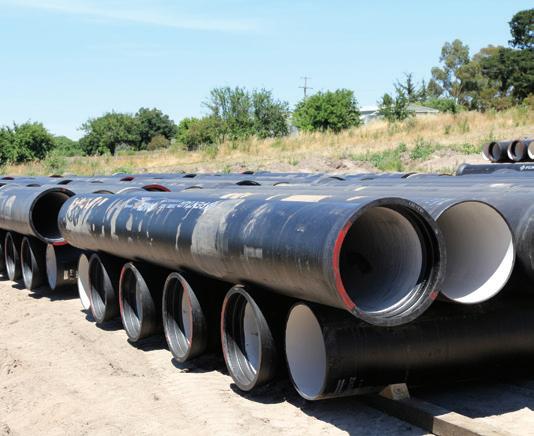
Coliban Water (VIC) has announced the construction company that has been awarded two contracts for the remaining Harcourt Rural Modernisation Project pipeline works.
Leed Engineering and Construction has been awarded the contracts for the backbone and reticulation network pipeline works.
Phone: +61 3 9720 1100 Email: sales@crusaderhose.com.au
www.crusaderhose.com.au

6 pump industry | Summer 2016 | Issue 14
NEWS
FLEXIBLE RISING MAIN 22
Bayswater VIC 3153
Industry Place
Australia
FLEXIBORE
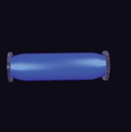
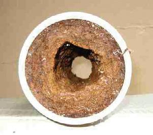
Flexibore reduces head loss, improves flow rate and eliminates iron bacteria build-up due to swelling under pressure. SWELLING ELIMINATES BUILD-UP
FLEXIBORE
A delivery program for completion of the pipeline, property reinstatement and the installation of customer connection points was developed in December 2015 and construction on the remaining works began in January 2016.
The Harcourt Rural Modernisation Project aims to upgrade irrigation channels to the Harcourt region and provide Harcourt residents with year round access to water through a piped system.
The piped system will replace the existing concrete and earthen gravity channel system.
The project includes approximately 65km of pressurised pipeline, two pump stations located at Faraday and Barkers Creek Reservoir and a balancing storage tank.
The project was put on hold in 2014 after disputes with previous contractor Redline Group, but work recommenced on the Barkers Creek and Faraday pump stations in November 2015.
Project superintendent, Mick Dunne, said the corporation was continuing to work towards having the project completed in time for the 2016/17 rural season.
Mr Dunne said, “With these two key contracts now awarded, and work already underway on the two pump station sites at Barkers Creek and Faraday, the project is progressing.
“While this procurement phase has been underway, we have been busy working behind the scenes with customers to ensure they are ready to connect to the new pipeline system when the project is completed next year.
“We are still working toward having the pipeline ready to deliver water to our 160 customers in time for the 2016/17 rural season,” Mr Dunne said.
To date 95 per cent of the backbone pipeline has been installed, with 17.7km out of the 19km and 25.4km out of the 44km (55 per cent) of the network pipeline now installed.
Hydroflo has a new home
The team at Hydroflo have a new and improved facility, with 10 tonne crane capacity and pump test facilities to 300kw.
You can now find Hydroflo at 115 Munibung Road, Cardiff, New South Wales.
For any enquiries you can contact the team on 02 4922 9020, and for more information about Hydroflo and the products and services they offer, head to www.bcip.com.au.

ONGA®
SSS SERIES
• All Stainless Steel construction wet end
• 4 models – 0.55 kW to 2.2 kW
• Flow rates to over 500 LPM
• Ideal for water transfer, irrigation, wash down and mild chemical use (Viton seal kit required)
• Liquid temperatures up to 85°C

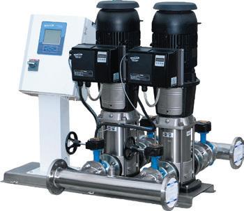
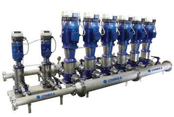
PVMI MULTI-PUMP SYSTEMS
• Up to 6 pumps
• Full 304 Stainless Steel wet end (316 available)
• Individual Variable Frequency Drives
• PLC Master Controller
• 316 Stainless Steel manifolds
• Main and individual isolators
www.pumpindustry.com.au pump industry | Summer 2016 | Issue 14 7 NEWS
www.onga.com.au www.southerncross.pentair.com
Global pump manufacturers ranked
Arecent survey by Timetric’s Mining Intelligence Center (MIC) has revealed the top global pump manufacturers in the mining industry, with one Australian company among the ranks.
Weir Minerals, Xylem and Kirloskar ranked as top three global pump manufacturers in the survey, accounting for 47 per cent of the total nominations.
The survey asked over 630 mine managers and senior decision-makers across more than 500 mines globally, to nominate the leading manufacturers (in first and second place) for different types of mining equipment, including pumps and submersibles, regardless of their own supplier.
With more than 240 votes and nominating 50 different manufacturers, combining nominations as the first and second leading company, respondents nominated Weir Minerals as the leading manufacturer of mining pumps, dewatering pumps and submersibles, receiving 24 per cent of the total nominations.
This was followed by Xylem with 14 per cent of the total nominations, and Kirloskar in third place with 9 per cent. AllightSykes was next with 5 per cent and KSB received 4 per cent rounding out the top five manufacturers.
The results show the strength of Weir Minerals in penetrating the market in five of the six regions,

where they received more than 20 per cent of the votes.
Xylem, however, is the only other top manufacturer that received nominations in every region, with the most mentions in Latin America of the leading manufacturers.
Australia, Asia and Africa appear to be more competitive markets for the leading players as four out of five of the top manufacturers received nominations in each of these regions.
Australian based company, AllightSykes, was mentioned the most in Australia, but was also considered as a leading manufacturer in Asia and Africa.
Timetric’s Senior Mining Analyst, Nez Guevera, said, “Conditions in mining industries around the world remain challenging as the fall in commodity prices have far-ranging impacts that will continue to weaken the unit sales of new mining pumps.
“However, there are opportunities for growth with the demand for replacement pumps, a bigger focus on recycling and reusing water, and investments made towards productivity improvements.”
8 pump industry | Summer 2016 | Issue 14 www.pumpindustry.com.au NEWS
Comprehensive Pump Support Reliable & Responsive Service
Engineered Pump Rebuilding
Since 1969, Hydro has built its worldwide pump service organization by bringing a high level of engineering expertise and quality service to the pump aftermarket. Hydro Australia works with our customers to evaluate and understand the root causes of pump degradation or failure and to provide unbiased engineering analysis, quality workmanship and responsive field service for improved plant operation.
Certified Service Centre
Hydro Australia has always been committed to Quality and Occupational Health & Safety. Hydro Australia holds the AS:NZS ISO 9001:2008 certificate in addition to the AS:NZS 4801 and AHSAS 18001 certificates.
Turnkey, Field Service and 24/7 Emergency Response
Hydro Australia’s Field Service team has extensive knowledge of pumps from most major manufacturers and provides turnkey service, installation / start-up supervision, field machining, vibration analysis, laser alignment, pump system troubleshooting and emergency field response 24 hours a day, 7 days a week.
Pump Parts
When you require a part and are facing a long lead time, Hydro Australia can meet your needs in a reduced time frame through our reverse engineering, patternless casting and integrated manufacturing processes. Hydro's engineers review and evaluate all parts to offer important upgrades and apply new technologies that will reduce wear and improve reliability.
Pump Testing - Managing Risk
Ensure your pump will perform as required. Hydro’s 5000HP Performance Test Lab, located in the United States, is compliant to API610 and Hydraulic Institute standards and can test horizontal, vertical, and submersible pumps.
Training
Hydro teaches practical solutions and troubleshooting techniques for common pump problems and offers specialized hands-on training programs. View upcoming courses online at www.hydroinc.com.
Call Hydro Australia at (03) 51650 390 with your pump service inquiries or contact Ross Bertolimobile: (0418) 581190 email: ross@hydroaustralia.com.au.
A Hydro Company Hydro Australia, Pty. Ltd. Hydro Australia Pump Service Centre Morwell, Victoria 3840 www.hydroaustralia.com.au (03) 51650 390
Vale Bob Moore
PIA Life Member, Robert J ‘Bob’ Moore sadly passed away on 5 November aged 88.
Bob was one of the true elder statesmen of the industry, having started working in pumps in 1955, and regarding himself as a lifelong “pump man”. He was a friend and mentor to many in the industry from the time he started in the industry in the 1950s until well past his retirement in the late 1980s.
Bob held a number of roles during his time in the pump industry, including stints at a number of leading Australian pump manufacturers including Kelly and Lewis and FN Bethune.
Bob was involved in the founding of the PIA (then APMA) in the 1960s and served as President of APMA 1975/76 and Chairman of the BPMA 1986/87.
His passion for pumps led him overseas, working as Managing Director for Mather and Platt’s Machinery Group based in Manchester UK. Later, he became Managing Director of Britain’s second largest pump company, SPP Group, and led a management
buyout of that particular company. This was followed by the successful floating of the company on the London Stock Exchange.
Bob’s extensive career reflects his passion and dedication to the pump industry both in Australia and abroad, and he inspired many in the industry with his skill and expertise.
After his retirement, Bob remained socially active with the industry through his relationship with the PIA.
He also continued his involvement with the industry through the writing and publication of two non-fiction works – Toss of a Coin, a reflection on his career in the pump industry, and Kelly and Lewis: a fine old engineering company - it’s rise and demise, which covers the history of Kelly and Lewis, the company where Bob spent more than half of his career.
You can read more about Bob’s career and life in Pump Industry’s profile of him, which can be viewed online at www.pumpindustry.com.au/ robert-j-bob-moore.

Vale Peter Snow
Peter Snow arrived on the Australian pumping scene when he came to Australia from the UK in the early 1960s from Mather & Platt (M&P), around the time that M&P acquired Kelly & Lewis. Peter resided in Sydney and was in charge of sales of M&P electric motors.
In the later years of his life he was employed by Weir Engineering and was heavily involved in both motor and boiler feed pump applications and sales. He was well known for his technical expertise and widely respected in the power generation field, particularly within the Electricity Commission of NSW and the State Electricity Commission of Victoria (as they were then known).
Peter also worked for Ingersoll-Rand during the 1970s where he headed the utility division in Sydney. Colleagues
from those days remembered Peter as a gentleman who was only too happy to pass on his knowledge to young engineers starting out.
Outside of work Peter was a very keen golfer and was a member of the Roseville Golf Club in Sydney for 48 years.
Sadly Peter passed away in hospital on 29 August 2015, aged 87. His birthday was only a couple of weeks earlier on 8 August. His passing followed his twin brother, who passed away only a few months before Peter did.
Peter never married but his brother had one daughter. His niece travelled from the UK and delivered Peter’s eulogy, which featured a touching mix of humour and solemnity.
10 pump industry | Summer 2016 | Issue 14 www.pumpindustry.com.au
Bob Moore.
NEWS
New pumps for QLD pump station
Three new KSB pumps have been installed in the City of Logan’s largest wastewater pump station in Queensland.
The three 8.4 tonne pumps were then lowered into a 20m-deep concrete dry well in the pump station.
Logan City Council Roads and Water Infrastructure Committee Chairperson, Don Petersen, said the 25 tonnes of infrastructure – valued at approximately $450,000 – were part of a major upgrade of the Alfred St wastewater pump station at Slacks Creek.
“The Alfred St pump station is really the workhorse of Logan’s wastewater network,” Mr Petersen said.
“It’s responsible for pumping 84 per cent of the city’s wastewater to the Loganholme Wastewater Treatment Plant for processing.”
Recent upgrades of the pump station valued at $6.8million have included replacement of switchboards, refurbishment of wet and dry wells and improvement of staff access for maintenance.
The City of Logan Council’s water infrastructure alliance has invested 22,500 working hours in the task.
“The three new pumps installed at Alfred St pump station replace three older models that were at the end of their useful life,” Mr Petersen said.
“Our new pumps are state-of-the-art and each can move around 1,300 litres of wastewater per second, lifting it 33 metres. They are an impressive 3m high and 1.5m in diameter.
“Council took the specification of the pumps very seriously as we want them to work efficiently and support the smooth operation of the city’s wastewater network for many years to come,” Mr Petersen said.
Mr Petersen said an engineer from the Logan Water Infrastructure Alliance visited the KSB factory in Germany to verify the pumps’ performance and witnessed them being readied for their six-week journey by ship to South East Queensland.
IRRIGATION & INDUSTRIAL
SUBMERSIBLE PUMPS & MOTORS
Moving Water Is Our Business
Franklin submersible pumps and motors are ideal in the most demanding applications and offer unmatched reliability, service, and availability.

Konichiwa Tsurumi
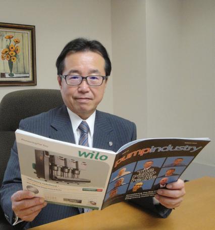
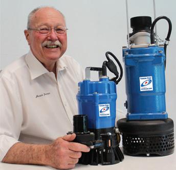
Our latest Pump Industry selfie comes to us from Japan, where Tsurumi Pump President Osamu Tsujimoto was spotted reading our magazine.


www.pumpindustry.com.au pump industry | Summer 2016 | Issue 14 11 NEWS
2079_Franklin New Pump Ad_FE807.indd 1 20/3/12 6:28:02 PM
FE942 06/13 www.franklinwater.com/au 1300 FRANKLIN (372 655)
The new face of the PIA
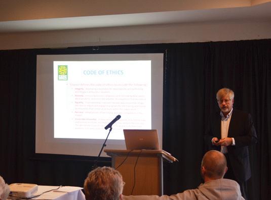
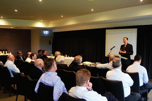
Last November the PIA gathered for its annual general meeting and dinner, an evening which was well attended by the association’s membership. Attendees learned about a range of new initiatives for the association, which will be rolled out across 2016.
The PIA was particularly excited to announce a new alliance with the Hydraulics Institute (HI), which will see the two associations working together to provide mutually beneficial outcomes for their members.
During 2015, the PIA signed a Memorandum of Understanding with the HI covering a range of activities, including:
• The sale of HI publications through the PIA website
• The promotion of HI webinars through PIA website
• The involvement of HI personal in selected Australian seminars
• Access to HI online training programs via the PIA.
The PIA sees this as a significant step in providing members with access to wide ranging information and data from a highly recognised international source.
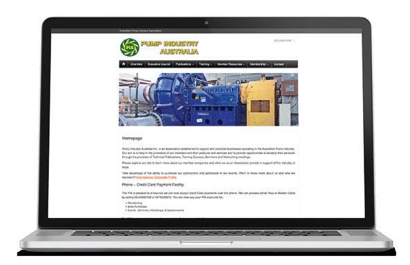
In conjunction with the HI partnership, the PIA has also launched a revamped version of its website, which has been designed to better promote the Association and its members.
The new-look site, which is now mobile friendly, features an online store offering a wide selection of pump industry related publications. This includes a selection of HI publications, which are now available under the agreement outlines above. The PIA website also features links to other sites which might be of value to members, newsletters, and access to a new members only section of the website.
In addition to this, there is a calendar listing all upcoming meetings and events, as well as a section listing all members and Life Members. The members section has been improved and includes sections containing past AGM minutes, technical papers, industry statistics, and much more.
Head to pumps.asn.au to check out the new site.
12 pump industry | Summer 2016 | Issue 14 www.pumpindustry.com.au
PIA NEWS
Ron Astall delivers his President’s Report at the AGM.
ANGUS FLEXIBLE PIPELINES PROVIDES INNOVATIVE LAYFLAT HOSE SOLUTIONS FOR A WIDE RANGE OF FLUID TRANSFER APPLICATIONS
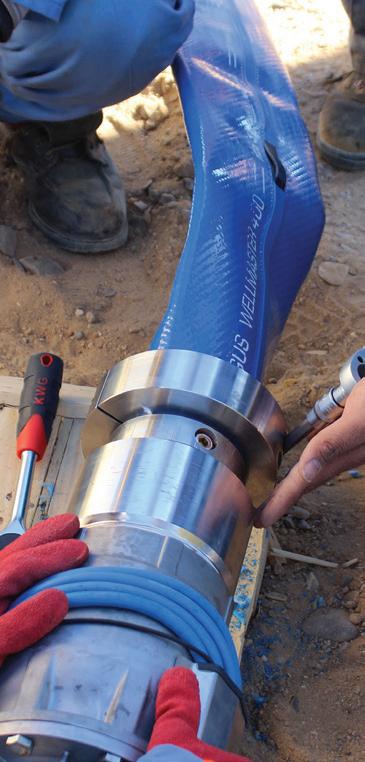
Wellmaster is the Industry Standard Flexible Rising Main for all types of ground water extraction and well-monitoring operations.
OVER 70,000 installations worldwide

Flexible Rising Main

Wellmaster Approvals:
Reg 31 UK
NSF 61 USA/Canada
DVGW W270 Germany
DM174 Italy
Institut d’Hygiene Switzerland
AFNOR France
AS 4020 Australia/NZ

www.pumpindustry.com.au pump industry | Summer 2016 | Issue 14 13 PIA NEWS
9/67 Depot Street BANYO Qld 4014 M: 0400 243 175 Ph: 07 3256 7624 Angus Flexible Pipelines Australia Pty Ltd
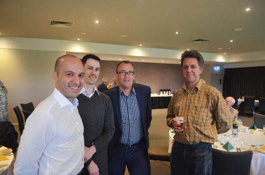
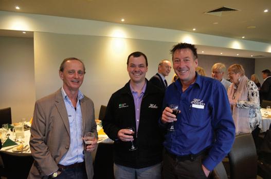
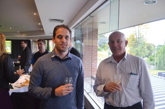
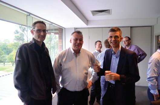
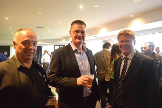
John McAndrew presented to attendees during the AGM (top left); before members enjoyed the chance to mingle with clients and colleagues afterwards.



www.pumpindustry.com.au PIA NEWS THE AWAKENING OF A MPump Pty Ltd NEW TECHNOLOGY sales@Mpump.co THE WORLDS MOST ADVANCED AODD FOR DISTRIBUTION OPPORTUNITIES: AUSTRALIAN BY DESIGN
PIA ANOINTS NEWEST LIFE MEMBER
At the PIA’s annual general meeting in November, John Link was named the newest Life Member for the Association.
John joins a prestigious group, with Life Membership only having been granted to 16 other members.
John started his first business – a crop spraying business – in 1959, before moving into pumps. According to John, “I think I was about the first person to set up a pump company whilst never having worked for an established pump company. Most of what I knew at the time was from the practical use of pumps when crop spraying.”
Over the 1980s and 1990s John’s business
went from strength to strength and grew into the business it is today.
“I have always been very passionate about my customers, employees and business,” said John. “Currently I have eleven employees, who I consider to be friends, and I run Link Pumps as a family business with pleasant customers who appreciate the informal friendliness of our service.”
John’s friends in the industry are many, and there are many who know they can turn to John for advice or assistance when they have a challenging pump that has them stumped.
Congratulations on achieving PIA Life Membership John.

www.pumpindustry.com.au pump industry | Summer 2016 | Issue 14 15 PIA NEWS
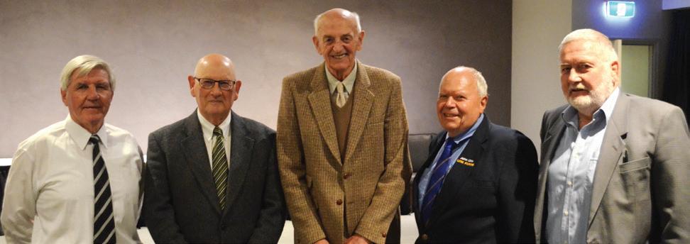
PIA Life Members Keith Sanders, Geoff Daniels, Bill Aitken, John Link and Bill Coulter.
PIA President Ron Astall presents John Link with his Life Membership.
Sulzer launches new process pump range
Sulzer has launched a new innovative SNS end suction single stage process pump range. It is designed to exceed the highest standards of performance and reliability, as well as the requirements of the ISO5199 standard.
The new pump range was developed for pumping applications in the pulp
and paper, water and wastewater, chemical processing, power, oil and gas, hydrocarbon processing, and general industries.
The SNS process pumps are designed to pump clean and slightly contaminated liquids, viscose liquids, and fibrous slurries. The unique hydraulic design ensures efficient


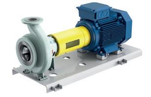
pumping with a low net positive suction head required across the whole pump range.
State-of-the-art simulation technology was used for designing the reliable and highly efficient impeller, casing, and shaft sealing. This resulted in very efficient hydraulics with improved shaft sealing conditions to ensure high reliability. Optimised patent-pending balancing holes in the impeller, together with a new design for the sealing chamber, guarantee ideal conditions for maximising the lifetime of the seal.
The innovative mechanical shaft seal solution provides easy assembly and maintenance. At the same time, it reduces the total cost of ownership by cutting down operation, maintenance, and downtime costs to a minimum. The compact pump design minimises shaft deflection and extends the shaft seal lifetime while decreasing unexpected shutdowns and overall maintenance costs.
Sulzer’s heavy-duty, rigid, and compact bearing units are leakage-free, which minimises unexpected shutdowns and reduces the maintenance costs. Standardised base plate, back pull-out design and flexible spacer coupling with an electric motor of standard feet make the installation quick and easy, thus bringing down the installation cost.
Due to the unique design, innovative features, and inventive standardisation of the SNS series, service and spare part inventory costs are also lower than they were previously.
The new SNS process pump is also the most efficient process pump range on the market, exceeding European Union requirements for energy-related products.
“With the new SNS product line, Sulzer provides its customers with very cost-effective pumping solutions, both on initial investment and on energy consumption. This represents a significant contribution to improve our customers’ profitability and environmental footprint,” said Cesar Montenegro, Division President Pumps Equipment at Sulzer.
16 pump industry | Summer 2016 | Issue 14 www.pumpindustry.com.au PIA MEMBER NEWS | PARTNER SOLUTIONS
Sulzer Australia Pty Ltd Phone 03-85813750 jonathan.fullford@sulzer.com www.sulzer.com TCO savings 21% MEI 0.7 ErP 2015 Modern industry demands more energy efficient pumping solutions so we’ve broken the conventions in the name of efficiency. The revolutionary design increases efficiency, lowers energy consumption and minimizes total cost of ownership. You just have to decide what to do with the savings you make? NEW Sulzer SNS pumps – Efficiency by design How Will the Savings Make You Feel? For more information on the new SNS pump series, visit www.sulzer.com/en/Products-and-Services.
New centrifugal pump range by Gorman-Rupp
Gorman-Rupp has announced the release of a new range of centrifugal end suction pumps through Australian distributor, Hydro Innovations. Called the 6500 Series, the range contains six solids handling models and three effluent pump models.
The range has been designed to have a very low lifecycle cost and minimal service requirements, making them ideal for delivering an excellent ROI. The Smart Scroll® volute allows installers to position the discharge in any one of eight positions, which increases flexibility in pump installation to help reduce installation costs.
Pumps are fitted with SiC/SiC oil lubricated seals, with separate oil chambers for seal and bearing oil and separate sight glasses so that operators can tell at a glance that oil levels and clarity are right in each chamber. The chambers are also separated by an atmospheric vent that keeps water pressure away from the bearings if a mechanical seal fails. Oversized bearings and alloy steel shafts (with options for stainless steel) add to the reliability, as does the double volutes designed into the higher head models.
Solids handling models have minimum 76mm spherical solids handling capability, flow rates from 20 litres per second (LPS) through to 900 LPS, and heads to 120 metres. They also have a side access (clean-out) port for easy access to pump interiors for inspection and blockage removal, while pusher bolt capability assists in the removal of the suction flange. Effluent models range in flow from 20 LPS through to 350 LPS, with heads to 155 metres.
For more information on these pumps, contact Hydro Innovations on 02 9898 1800 or by emailing info@hydroinnovations.com.au.


www.pumpindustry.com.au pump industry | Summer 2016 | Issue 14 17 PIA MEMBER NEWS | PARTNER SOLUTIONS
Operating pumps at partial capacity: causes of vibration
By Dr Gary Dyson, Managing Director, Hydro Global Engineering Services (UK) and Chandra Verma, Chief Design Engineer, Hydro Australia
It can be common for pumps to operate at low flow. This is inevitable in many cases, as the nature of many process operations place varying demands upon the equipment.
Whilst operating at low flow, a machine is under much greater duress than at most other operating flows. To understand why operating at extreme low flows can cause pump problems, it is instructive to analyse the nature of the flow through the machine.
Using computational fluid dynamics, Hydro Australia has been able to model this flow picture. By truly understanding the nature of the flow regime Hydro Inc Engineers have been able to re-design and refine equipment for wider operating regimes and greater mean time between failures.
Hydraulically generated vibration
The days have long passed where pump vibrations were viewed as largely a matter of mechanical balance. Nowadays, we recognise that, even if a pump has near perfect mechanical balance, it will still exhibit remnant vibrations.
The intensity of this remnant vibration turns out to be flow related, with a minimum at or around best efficiency point. Clearly the hydraulic design of the pump has some significance in its vibration behaviour.
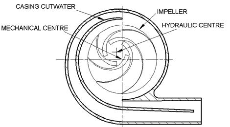
Vibration at “one times” shaft rotational frequency is frequently ascribed to driver misalignment, or mechanical balance. However, this can also be caused by the impeller if it is machined eccentric to its hydraulic centre. The impeller behaves like a hydraulic cam while in the pump, even though it may be in near perfect mechanical balance in air. See Figure 1.
Hydraulically generated vibration – vane pass
From a hydraulic design standpoint, vibrations at vane pass frequency are always inherent, due to the way impellers generate head.
Each vane had a pressure differential between the top and under side of the van. This pressure differential results in a velocity difference over both surfaces of the vane.
This difference propagates through the passage out into the collector. Thus the collector, and anything connected to it, will experience a fluctuating velocity field once per impeller blade pitch. These result from the turbulent ‘wake’ generated at the trailing edge of the blade, which is fuelled by the two different velocity streams mixing out. See Figure 2.

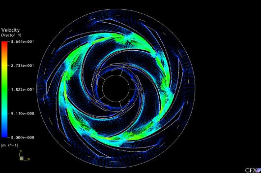
At partial capacity this flow picture greatly deteriorates, as shown in Figure 3. Each passage is filled with slow moving fluid. The diffuser passages are stalled and the velocity is heavily time dependent. Operated in this condition it is easy to see how vibration and heat can become a problem for pumps reliability.
Vibration caused by inlet back flow
This phenomenon is always present within a pump operating at low capacity, and always contributes to the vibration level.
High-energy liquid is expelled from the impeller eye. This expelled liquid dominates the suction passage, occupying
18 pump industry | Summer 2016 | Issue 14 www.pumpindustry.com.au
PIA MEMBER NEWS | PARTNER SOLUTIONS
Figure 1. Hydraulic cam causing high 1x vibration.
Figure 2. Varying velocity experienced by diffuser.
Figure 3. Complex nature of the flow regime at low capacity.
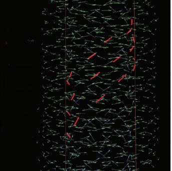
the two-thirds of the flow area from the pipe outer diameter downwards towards the channel centreline (see Figure 4). The extent that the expelled liquid fills the suction channel remains unchanged with distance from the impeller. This flow spirals helically down the periphery of the suction pipe.
Each impeller blade generates individual streams. The tangential velocity imposed on the regime by the impeller dominates the flow causing the helical spiral angle to be approximately equal to the blade inlet angle. This angle does not diminish with distance from the impeller implying that both the tangential and axial components of the velocity decay proportionally to maintain this angle.
The inner third of the suction channel area contains a spiralling core of slower moving fluid. Viscous effects transmit tangential energy from the high-energy peripheral flow and drive this core in a helical spiral counter to the direction of pump rotation. Flow is dominated by the axial component of the velocity and tangential forces exerted by the peripheral flow cause the inner helical flow angle to be approximately double the outer angle. Again the helical spiral angle remains
ABOUT THE AUTHORS
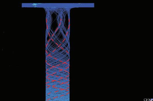
constant. See Figure 5.
Whilst these velocity streams are not responsible in the computational analysis for a vibration component, this cannot be said in a real situation. Pump suction and piping designs contain discontinuities such as splitters, elbows and reducers.
The velocity streams impacting on these features contribute to the vane pass frequency vibration.
Conclusion
Being able to visualise the nature of the flow with a centrifugal pump allows a greater understanding of how these flow impact on the reliability of the equipment.
Vibration is no longer viewed as merely a function of the mechanical balance but is also influenced by the design of the bladed components, the operating philosophy and the precision of the build of the pump.
By using advanced computational techniques it is possible to refine and manage these contributing factors to minimise hydraulically generated vibration.
Dr Gary Dyson is the Managing Director of Hydro Global Engineering Services, based in the United Kingdom and Chandra Verma is the Chief Design Engineer for Hydro Australia, based in Morwell, Victoria.
HYDROVAR
• Motor or wall mountable
• Fully programmable on site
taking
• Software specifically designed for pump operation, control and protection
• High level hardware design
• More flexibility and cost savings
• Energy savings up to 70%
• Simple mounting “clip and work”
• Multi-pump capability up to 8 pumps

1300 4 BBENG


www.pumpindustry.com.au pump industry | Summer 2016 | Issue 14 19 PIA MEMBER NEWS | PARTNER SOLUTIONS
Figure 4. Internal core of spiralling fluid in suction channel.
Figure 5. Helical spiralling inlet backflow at suction duct periphery.
Ph:
www.brownbros.com.au
®
Call us today for a Hydrovar® technical brochure to see how we can deliver your pumping solutions. DELIVERING PUMPING SOLUTIONS 03/15
, the modern variable speed pump drive
pumping to a new level of flexibility and efficiency.
Produced water treatment
The effective separation of oil and water is a vital part of any oil and gas production facility. The preservation of oil droplet size and prevention of emulsion formation is crucial to the effective treatment of oily water.
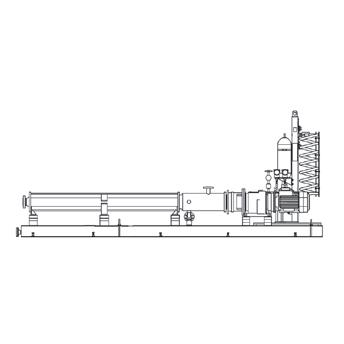
Feeding of oily water separation equipment, either gravimetric or dynamic, is optimised by low shear pumping equipment. The slow running speeds and gentle action of progressive cavity pumps eliminates problems caused by emulsion formation.
Feeding the oil/water mixtures to the separator using a high quality progressive cavity pump, from a reputable global manufacturer, is a ‘state of the art’ solution for maximising the overall efficiency of the system. No demulsifying chemicals need to be added, so operating costs are substantially reduced. Specifying even wall stator technology reduces internal slippage and shear, while also offering a compact design where space is at a premium.
Flow rates can be regulated via simple speed control which eliminates the need for control valves and spillback lines (as used with centrifugal pumps). The removal of these valves further reduces points of shear in the process system. Semisubmersible, vertically mounted progressive cavity pumps provide a flexible solution in restricted space and when fitted in a can, this configuration will optimise the NPSH available and the process conditions.

Produced water recycle pump
Conveying capacity:
18.2 m³/hr (80 USGPM)
Pressure: 14.9 bar (216 psi)
Material EN 1.4501
API 682 plan 53B seal system
Benefits include:
• Compact design, with even wall stator, saves space
• Flexible installation and use of semi-submersible in-can design, provides compact footprint
• Minimal shear on oil droplets prevents emulsion formation
• Variable flow rate is controlled via simple speed adjustment to optimise efficiency of separation systems
• Pumps can operate with low NPSHr 0.3m (0.98ft) eliminating the need for a separate booster pump
• Eliminates the need for adding chemicals, providing substantial cost savings.
For more information, or to request a free site survey to establish if SEEPEX can help you, contact SEEPEX Australia on 02 4355 4500 or info.au@seepex.com.

Slop oil pump
Conveying capacity:
25.6 m³/hr (113 USGPM)
Pressure: 13.4 bar (194 psi)
API 682 Cat 2 seal 53B system
Flare drum pump
Conveying capacity:
11.28 m³/hr (50 USGPM)
Pressure: 18 bar (261 psi)
API 682 Plan 53B system
20 pump industry | Summer 2016 | Issue 14 www.pumpindustry.com.au
INDUSTRY NEWS | PARTNER SOLUTIONS
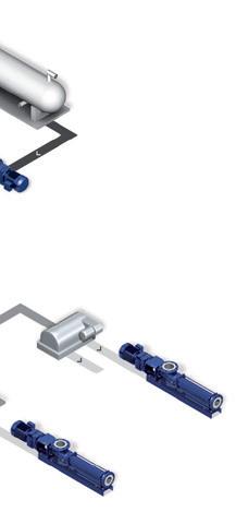
FLOW CHART BASED ON PRODUCED WATER TREATMENT
WATER TREATMENT

APPLICATIONS
1. BE range pumps lift oil from the slop oil tank to the separator
2. BN / BE range pumps transfer product from the knock out drum to the separator
3. BN / BE range pumps transfer product from open and closed drains to the separator tank
4. BN / NS / N range pumps with even walled stator technology transport produced water to hydrocyclones
5. BN / NS / N range pumps transport reject oil back to the upstream separators or water to induced gas flotation (IGF) units


WHY REPLACE WHEN YOU CAN ADJUST?


SEEPEX Smart Conveying Technology extends the life of your stator. Adjustment of the retaining segments takes just 2 minutes and restores 100% pump performance.
Tests have shown up to 3x stator life compared to conventional progressive cavity pump design Join the smart revolution and test our innovation “Smart Conveying Technology”.


SEEPEX Australia Pty. Ltd. Tel +61.2.4355 4500 pvila@seepex.com www.seepex.com

www.pumpindustry.com.au pump industry | Summer 2016 | Issue 14 21 INDUSTRY NEWS | PARTNER SOLUTIONS produced water oily water water hazardous drains water oil oil RANGE BN knock out drum pump RANGE BE RANGE BN centrifuge / hydrocyclone feed pump RANGE BN open drain pump RANGE BN reject oil pump RANGE BN closed drain pump RANGE BE canned pump RANGE BN reject oil pump 9 PRODUCED WATER TREATMENT FLOW CHART BASED ON PRODUCED
slop oil tank separator centrifuge hydrocyclone closed drain tank knock out drum APPLICATIONS 1. BE range pumps lift oil from the slop oil tank to the separator 2. BN / BE range pumps transfer product from the knock out drum to the separator 3. BN / BE range pumps transfer product from open and closed drains to the separator tank BN / NS / N range pumps with even walled stator technology transport BN / NS / N range pumps transport reject oil back to the upstream
Improved safety in explosive atmospheres
KTR has expanded its ROTEX® coupling line with the new ROTEX® non-sparking for maintenance-free use in potentially explosive environments. This failsafe innovation assures operation in cases of spider element wear while reliably preventing sparking.
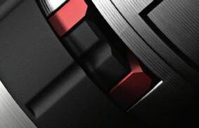
The jaw geometry consists of a conductive high-tenacity plastic that is injected onto the hub body which continues to be made of steel or other metals such as aluminium. The newly developed synthetic material prevents any static charging and is also designed to be so hard wearing that even in cases of elastomer wear out, torque will still be transmitted without any danger of sparking. As a result, maintenance work can be postponed to a convenient time frame.
The failsafe and maintenance-free ROTEX® non-sparking is certified under EU directive 94/9/EC (ATEX 95) and thus deemed suitable for the use in explosive atmospheres. The shaft coupling has a compact design and can be axially plugged in. It offers good dynamic properties, excellent vibration damping
and a low moment of inertia.
The ROTEX® non-sparking ensures dampened torsional vibration during power transmission and absorbs shocks generated from imbalanced machinery.
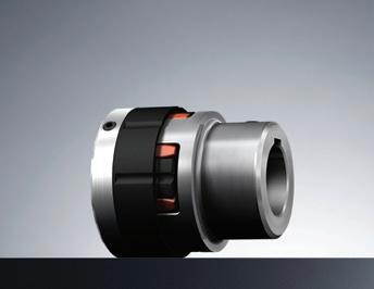
The new explosion-proof ROTEX® non-sparking coupling displaying injected jaw geometry on one side.
The new coupling is also available in various double-cardanic finishes for large shaft misalignments that maintain low restoring forces and ensure sound dynamic properties.
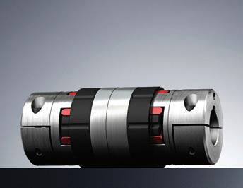
With the double-cardanic design, the centrepiece comes with injected jaw








22 pump industry | Summer 2016 | Issue 14 www.pumpindustry.com.au
INDUSTRY NEWS | PARTNER SOLUTIONS
geometry
The ROTEX® Non-Sparking is exclusively distributed in Australia and New Zealand by Deanquip. For further information or technical support, please contact +61 3 9729 0201 or send an email to sales@deanquip.com. www.ktr.com Thanks to new material and production technologies the fail-safe ROTEX® Non Sparking can continue to operate if the spider has worn off with no danger of sparking, ensuring a carefree operation in hazardous locations. More safety for hazardous locations Phone: +61 3 9729 0201 www.deanquip.com Your KTR distributor in Australia.
on both sides.
Drive solutions for the water world
FCR Motion Technology is proud to present the Emotron FDU series of pumping variable speed drives from CG Drives & Automation.
Born as Emotron in 1937, Emotron has developed solutions for the control and monitoring of electric motors. With over 30 years of experience in water handling applications, Emotron’s pumping solutions guarantee longer service life, flexibility, system protection and improved cost-efficiency.
The rugged construction of the IP54 FDU variable speed drive is designed to withstand the toughest environmental conditions, with power ranging from 0.75 to 3,000kW. The full featured FDU is designed to regulate the motor speed to control flow, and pressure with an in-built suite of pumping specific features which include:
Multi pump control – The control of up to seven pumps regulating the flow/ pressure of the system, selecting the pump to give them all equal running time. Should one pump fail, the system
automatically selects the next available pump, avoiding unnecessary down time.
Auto rinsing – When running at low speed, sludge can build up reducing the efficiency of the pump. With auto rinsing the system can be programmed to run at full speed at certain intervals or on start up to prevent this sludge building up.

System sleep – This function can be activated in low flow or no flow situations to prevent the pump from overheating and reduce energy consumption.
Damage protection – The built in shaft power monitor uses a unique load curve protection function to detect situations such as dry-running, cavitation, overheating, blocked pipes, etc.
Energy saving – By regulating the speed of the pump to control flow or pressure, the system will only use the power required to deliver the required output, saving considerable energy when demand is low.
Simple descriptive text – Simple descriptive programming parameters and operating units for pressure, flow, speed, etc, can be customised to suit user needs.
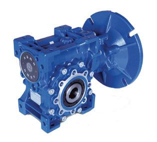
FOR ALL YOUR PUMPING APPLICATIONS MOTOVARIO INLINE
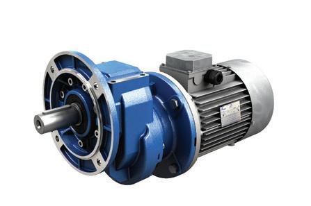
• Increased mechanical performances


AND WORM GEARBOXES

• High external radial capacity and mechanical strength
• Reduction ratios between 1.3 and 280
• Specific reinforced seals, taper roller bearings and thrustbearings available
EMOTRON DRIVES, SOFT STARTERS AND SHAFT POWER MONITORS


• Torque control, smooth start and stop modes to avoid water hammering
• Dedicated software for pump control systems
• Programmable timers with real time clock
• Early warnings and safety stops
• Optimized monitoring for energy saving
• Control of up to 7 pumps
• IP20/21 and IP54 rating www.fcrmotion.com
(03) 9362 6800
www.pumpindustry.com.au pump industry | Summer 2016 | Issue 14 23 INDUSTRY NEWS | PARTNER SOLUTIONS
For more information visit www.fcrmotion.com or call 03 9362 6800.
Universal mounting foot mount, flange
foot/flange
mount and
mount
From humble beginnings to dramatic expansion
Since the relaunch of the Tsurumi product range in Australia four years ago, the results have been nothing short of astonishing. When Aussie Pumps began supplying Tsurumi Pumps, the company found that Tsurumi’s reputation was well known by pump specialists but not necessarily by users such as farmers, consultants and even mine engineers.
“We knew the quality and standing of Tsurumi internationally and shared a desire to make the brand a market leader in Australia. This would match the standing and reputation the product already has in North America, Europe and South East Asia,” said Aussie Pumps Chief Engineer John Hales.
Tsurumi has spent 91 years becoming the world’s number one manufacturer of electro-submersible pumps with an annual production capability in excess of 1.4 million units. This story charts the progress of the dynamic Japanese company.
Humble beginnings
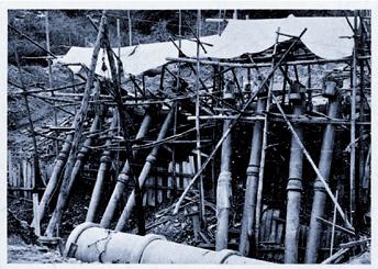
The company started out in 1924 as a manufacturer of agricultural vertical shaft pumps. The primary function was for applications in paddy fields and Japanese horticulture. By 1951 the company had grown into Tsurumi Manufacturing Company Ltd and had produced a two-stage vertical shaft pump for construction dewatering use.
That evolution of agricultural pumps was a huge breakthrough for Tsurumi. It introduced them to the construction market, a vital industry during the rebuilding of post-war Japan.
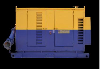
PUMP HIRE and REPAIRS
Repairs
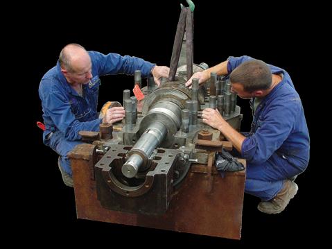
Our continuous exposure to a wide range of problems and Industrial applications across numerous markets, has ensured we have the know how to handle pump repairs of all sizes and complexities, including re-engineering, testing, laser alignment and condition monitoring.
With each repair job we implement a thorough inspection process and follow strong control and stringent acceptance criteria carried out by a team dedicated to keeping your pump working at optimal performance.
Hire
Link Pumps has been servicing the needs of Australian Industry with pump hire solutions for over 50 years, and as such has built a reputation for being able to solve complex engineering problems and additionally undertake complex setups with complete reliability notwithstanding working to the exacting standards of environmental and occupational health and safety expected by that of our customers and regulatory authorities.
In 1955 the company launched the first electro-submersible pumps, the EP Series. Now there was no stopping Tsurumi.
With that technology and a booming domestic market, the company threw itself into the development of a range of new products. This included a newly developed lightweight dry type motor series. The dry motors replaced the conventional oil filled motor, with major features and benefits for users. By 1965,
For all your Pump Hire and Repair needs you can’t go past Link Pumps, so call us now…. We perform, Anytime, Anywhere
4 Ponting Street, Williamstown North,3016
24 pump industry | Summer 2016 | Issue 14 www.pumpindustry.com.au INDUSTRY NEWS | PARTNER SOLUTIONS
LINKPUMPS
Tsurumi started producing two stage vertical shaft pumps in 1951 for the construction market.
Phone: (03) 9391 9600 Email: sales@linkpumps.com.au

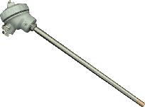
the submersible pumps incorporated built-in circle thermal protectors (thermostats) to protect the motor from overheating.
During this period of rapid growth the company opened an Osaka sales office and a separate branch in Tokyo. In 1965, a Sapporo sales office was added in Hokkaido, and another sales office opened in Fukuoka (on Japan’s island of Kyushu).
In the early 70s a major breakthrough in the introduction of a solids handling impeller was achieved by the company. Unique to Tsurumi at the time, the company introduced the concept of a vortex style impeller which enables the passage of solids without clogging or excessive wear on the pump end.
By now Tsurumi, guided by Mr Tsujimoto as President, was sensing that there was a world outside Japan for the company’s products. In the early 70s Tsurumi started exporting through trading houses and entered the European, North American, South East Asian, Australasian and Middle East markets. That explosion of activity was generated by the company’s quality standards, extremely competitive prices and innovative designs.
By 1979 Tsurumi had established subsidiary companies in Hong Kong, Singapore and the United States. To keep pace, a brand new factory was built on a green-field site in Kyoto. A new plant designed to dramatically increase productivity included an enhanced R&D department and test rigs capable of handling pumps big enough for flood mitigation and municipal sewage applications.
By now Tsurumi had come an awfully long way from vertical shaft agricultural pumps and had developed a range of dewatering pumps, slurry pumps, sewage pumps and even aerators. Driven by worldwide demand they provided realistically priced products that were deemed to be of a level of reliability not found elsewhere.
“The company philosophy is very typically Japanese,” said Mr Hales. “It’s a combination of modern innovation combined with traditional Japanese attention to detail,” he said.
In the year 2000 the Kyoto plant acquired ISO 14001 certification.
International growth
By 2005 Tsurumi had established additional subsidiaries in Germany, Taiwan, Malaysia and Shanghai. Additional subsidiary companies would be established in the coming years in Korea, Thailand and in the Middle East.
Today the Kyoto plant represents a massive development of manufacturing and engineering excellence. Modernized and developed using the most modern robot technology, the production capacity from this one plant alone is over one million units per year.
Tsurumi philosophy
Tsurumi traces its beginnings back to the projects it undertook to improve the harsh conditions in Japanese farming villages, introducing vertical irrigation pumps more than 90 years ago.
During the rebuilding of Japan after the Second World War, Tsurumi was the first domestic company to establish submersible pump technology. During that subsequent period of high economic growth Tsurumi contributed to the expansion of many industrial sectors by assisting in the development of social infrastructure through water related urban planning and flood control projects.
The company’s capability enabled it to participate in major Japanese projects like the Akashi-Kaikyo bridge
(between Honshu and Awaji Island across the Akashi Strait).
The philosophy of the company has always been to be ‘water and people friendly’. Tsurumi encourages creativity, harmony and passion from the President, Mr Osamu Tsujimoto, to staff. The staff are committed to facing the challenges delivered by changing times.
The message for Australia
Australian Pump, a well-established and progressive Australian company, are absolutely committed to bringing Tsurumi to the market.
“Capitalising on the company’s engineering, production, and perhaps more importantly their philosophy, make them an unstoppable force in the pump business” said Mr Hales. “Working with Mr Tsujimoto and the Tsurumi team means we get incredible engineering support. A positive, progressive attitude and access to products that are built to quality standards means Australian customers receive the world’s best.”
Australian Pumps Tsurumi business has expanded dramatically since the establishment of a Tsurumi Pump Bank. This bank puts millions of dollars worth of Tsurumi stock at the disposal of Australian customers.
“Providing the combination of the best product, at the best price and short lead time is our goal,” said Mr Hales.
For further information including detailed catalogues, technical data and material on the huge range of submersible pump products visit www.aussiepumps.com.au or contact Australian Pump Industries on 02 8865 3500.
www.pumpindustry.com.au pump industry | Summer 2016 | Issue 14 25 INDUSTRY NEWS | PARTNER SOLUTIONS
Mr Osamu Tsujimoto President Tsurumi masterminded the robotised production plant in Kyoto.
Mr John Hales, Aussie Pumps’ Chief Engineer with the latest evolution of Tsurumi dewatering pumps.
Efficiency and flow monitoring
Some studies have shown that 30 to 50 per cent of the energy consumed by pump systems could be saved through equipment or control system changes. The fact is – monitoring pump efficiency and rate of wear will save you money.
In today’s world where there’s an increased awareness of the need to use energy efficiently and operate in a manner that is sustainable, in the pump industry there is constant pressure on users to reduce energy wastage, reduce costs and reduce pollution.
The saying goes “If you cannot measure it, you cannot manage it”. This is also true for energy wastage and being able to know where and how much energy is wasted, is the first step to reducing energy wastage. The question that needs answering is: If I want to save money, when is the ideal time to rebuild my pump?
Real-time efficiency monitoring or pump tests?
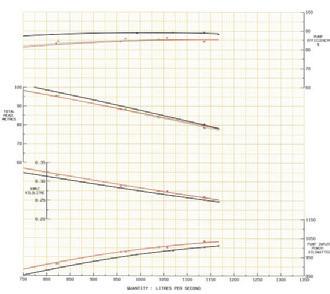
The Marcor Pump Efficiency Monitor measures real-time pump energy wastage and flow rate accurately, using the thermodynamic method as
described in ISO5198. It allows you to manage your pump and pumping system’s performance in real-time rather than relying on periodic pump test results. Any condition that arises which can lead to energy wastage or pump damage, can be responded to immediately.
The Pump Efficiency Monitor was developed to provide pump and asset managers with a reliable tool to accurately measure and monitor energy wastage and to be able to confidently forecast maintenance activities. This efficiency monitor provides all the necessary information to realise significant savings.
For the price of two or three pump tests, pump end users can now monitor the performance of their pump in
real-time for at least the next 20 years. Pump management staff can spend more time managing pumps and pump systems to reduce energy wastage, and less time collecting pump performance data in the field.
The device uses the thermodynamic method for determining the energy losses in the pumped fluid. This method has the advantage of determining percentage energy losses by measuring the changes in pressure and temperature across a pump. It does not require a flow meter reading.
The key parameters the monitor measures are energy wastage (%), pump efficiency (%), cost of pumping (kWh/kl), flow (l/s), head (m) and power (kW).
For more information on how the Marcor Pump Efficiency Monitor can help your business, visit www.marcor.com.au or call 08 8326 7171.
Pump Performance Testing
S In-situ pump performance testing
S Portable pump test equipment
S Real-time pump efficiency monitoring
S Differential Temperature Transmitters (1mK)
S Pump test equipment rental S Reduce your energy bill S Extend the life of your pumps S Reduce greenhouse gas emissions



26 pump industry | Summer 2016 | Issue 14 www.pumpindustry.com.au INDUSTRY NEWS | PARTNER SOLUTIONS
.com.au Serving the industry - Caring for the environment E: enquiries@marcor.com.au. Ph: 0450 027 110
Let us:
Not to be sniffed at
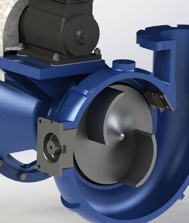
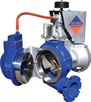
New to the AllightSykes range of Sykes pumps, the SW has been specifically designed for sewage and wastewater applications. The patent-pending SW range is capable of pumping large solids up to 100mm. It chops and shreds debris, rope, and other types of stringy items that normally partially or fully clog pumps.
The SW pump range boasts an array of new and exciting features to ensure optimum pump performance in times of need. To test and prove this patent pending concept, Sykes Pumps have carried out extensive field trials with various water authorities with excellent results and feedback.
The SW pumps are based on the market leading Sykes heavy duty and robust CP range with significant commonality and interchangeability of key components.
The SW features a fully open non clog design impeller capable of handling large
solids. A shredder claw that is designed to tear and shred stringy material that normally would wrap around the impeller and clog the pump. The cutting pockets in the front wear plate chops and shears large object allowing them to be passed through the pump. The inspection insert is designed to allow easy access to the volute chamber enhancing maintenance and repair activities.
Optional extras include soundattenuated acoustic canopies, road registerable trailers, heavy duty skid base, remote pump monitoring, increased fuel capacities and fuel tank bunding.
For more information on the range of Sykes pumps
freecall 1300 255 444
SEWER & WASTE PUMP RANGE
New to the AllightSykes range of Sykes pumps, the SW has been specifically designed for s ewage and waste water applications.
The patent-pending SW range is capable of pumping large solids up to 10 0mm. It chops and shreds debris, rope, and other type stringy items that typically clog pumps. For more information on the Sykes range of pumps, visit our website or freecall 1300 255 444
www.pumpindustry.com.au pump industry | Summer 2016 | Issue 14 27 INDUSTRY NEWS | PARTNER SOLUTIONS
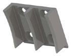
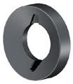
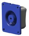
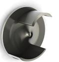
INSPECTION INSERT CUTTER POCKET SHREDDER CLAW NON-CLOG IMPELLER
experts FREECALL 1300 255 444
to speak to one of our de-watering
visit www.allightsykes.com or
to
to a dewatering experts.
available,
speak
Optimised water solutions
Dating back to 1982, the Shakti Pumps story is one of a company which has gone on to produce stainless steel submersible pumps, energy saving submersible motors, vertical multistage centrifugal pumps, pressure boosters, self-priming, end suction, open well and solar pumps. In the three decades since it was established the company has grown phenomenally and has become one of the few pioneers in the world to produce 100 per cent stainless steel submersible pumps.
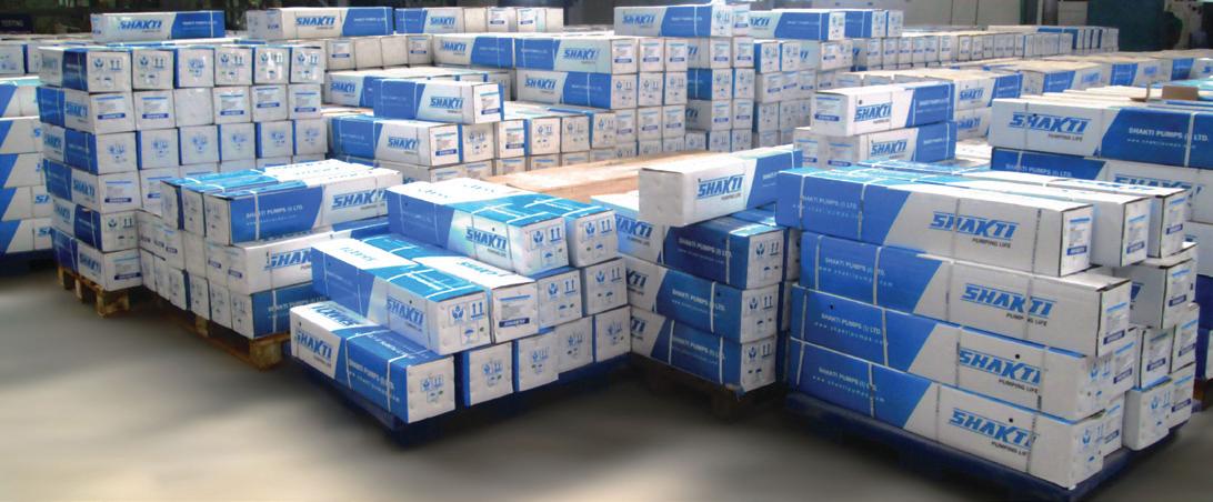
The company employs international best practice technology to manufacture its products. This technology includes cutting-edge Japanese and European machines, modern CNC machines and stamping machines.
Thanks to dedicated efforts in R&D and technological innovation, Shakti Pumps has emerged as a leading entity in the pump industry, catering to domestic as well as international markets, with a notable reach of more than 100 countries.
Today, Shakti Pumps is a leader in the global pump industry, thanks to stateof-the art technology and continuous innovation. Their pumps have applications in raw water intake, drinking water treatment, water distribution, wastewater control and flood control, and wastewater treatment.
Shakti Pumps supplies a broad range of equipment and solutions designed specifically for water utility applications. Shakti is at the forefront of promoting and facilitating energy efficient and
sustainable technology, ensuring that water supply and wastewater facilities meet future challenges and regulations.
Shakti domestic pumps are ideal for use in homes, where they are used to maintain water pressure in taps and for general applications like watering gardens and operating fountains.
Shakti Pumps also meet varied agricultural needs, be it drip irrigation, agricultural sprinkler systems or watering crops; and they are used in industries for a variety of purposes including cutting and grinding, firefighting, managing sewage, and the heating and cooling of systems.
Shakti Pumps is a major force in places like hotels, corporate buildings and shopping malls, where heavy pressure and boosting is required. The company supplies pumps with the latest digital technology for cooling, heating and wastewater management.
Shakti Pumps also has a range of solar pumps, ranging in size from 0.37 to 75kW, that are simple and easy to operate, offering 40 per cent more
discharge than other ordinary pumps.
From draining flooded water from areas like basements, car parks and empty cesspools, to managing sewage in a water treatment plant, Shakti Pumps are widely used in the domestic, industrial and commercial sectors.
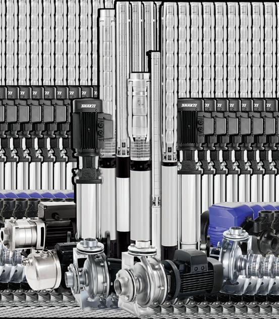
The range of Shakti Pumps products includes:
• Submersible pumps and motors
• Solar pumps
• Vertical multistage centrifugal pumps
• Pressure booster pumps
• Mono block end suction pumps
• Sewage pumps
• Immersible pumps
• Open well pumps
• Hydropneumatic booster systems
• Self-priming pumps.
28 pump industry | Summer 2016 | Issue 14 www.pumpindustry.com.au INDUSTRY NEWS | PARTNER SOLUTIONS
more information please visit the company website - www.shaktipumps.com.au.
For

State of the Industry in 2016: adapt, diversify, survive
Recently Pump Industry undertook the most comprehensive survey we’ve ever conducted in order to present a detailed analysis of the industry’s outlook for 2016.
After a challenging 2015, coming off the back of the depressed oil price and the global fall in commodities prices, we were keen to measure and understand our reader’s expectations for the year ahead. Are we expecting the challenges of 2015 to continue? Or is the mood more optimistic, thanks to new opportunities in water, wastewater and energy efficiency?
The data from our respondents suggests it’s a bit of both. When asked how they expect their own company to perform in 2016, our respondents are feeling positive, with 45 per cent expecting their own performance to be better than 2015; and 44 per cent expecting to perform about the same. Only 8 per cent of respondents believe performance in 2016 will be worse than 2015, and the remaining 3 per cent were unsure. These responses are shown in Figure 1.
Interestingly, while our respondents are feeling positive about their own performance in 2016, their thoughts about the industry more broadly aren’t necessarily reflective of this. 49 per cent of respondents believe the industry will perform about the same as 2015, while a much smaller 22 per cent expect the industry as a whole to improve. 18 per cent expect the industry to perform worse than 2015, and the remaining 11 per cent were unsure. These responses are shown in Figure 2.
The discrepancy between personal performance and industry performance could be down to a number of reasons; perhaps our respondents are feeling more positive about their own ability to ride out the challenges of 2015 and prosper more in 2016. Or perhaps the difference suggests that the industry has a slightly less positive view of the broader industry’s performance which is not necessarily justified.
Performance by vertical
To gain an understanding of how the pump industry is performing across
a range of key verticals, we asked our respondents about their performance in these industries in 2015, and we asked our respondents how they expect to perform in these industries in 2016. From the responses we’re able to gain an insight into the best and worst performing verticals, according to our respondents, and gain an insight into which verticals show the most promise in 2016.
Figure 3 highlights the performance of our respondents across several verticals. From the baseline, this graph highlights the verticals in

Our respondents have noted a lack of major projects is having an impact on the pump industry.
30 pump industry | Summer 2016 | Issue 14 www.pumpindustry.com.au
STATE OF THE INDUSTRY
which businesses overall ‘decreased somewhat’’ or ‘decreased significantly’ (bar below the baseline) and the verticals in which businesses overall ‘increased somewhat’ or ‘increased significantly’ (bar above the baseline).
From this graph we can see that our respondents had a challenging year across a number of sectors, with those involved in mining the hardest hit. As for how our companies expect to perform in 2016, respondents believe that conditions will improve across a number of verticals. While it’s anticipated that

the mining, plastics and rubber and pulp and paper sectors will continue to be challenging markets to operate in, our respondents believe in all other sectors their performance will increase or increase significantly.
In particular, the irrigation, water and wastewater, food and beverage and building services and HVAC sector all seem poised to offer pump company’s significant growth – a trend which continued to present itself throughout the survey.
How do you expect your company to perform in 2016?
www.pumpindustry.com.au pump industry | Summer 2016 | Issue 14 31 STATE OF THE INDUSTRY
Worse than 2015 About the same as 2015 Better than 2015 Don't know
8% 44% 45% 3% Figure 1.
How do you expect the Pump Industry overall to perform in 2016?
External factors affecting the industry
To gain an understanding of how macroeconomic conditions, such as the value of the Australian dollar, are impacting the Australian pump industry, we asked our respondents to describe their positive or negative impact on the industry.
Analysing the responses, we’ve been able to generate graphs which represent which of the factors will have the greatest impact on the industry (Figure 4) and then order these from the impacts that will have the most negative impact to those that will have the most positive impact (Figure 5).
Figure 4 shows us that the performance of the mining industry, the value of the Australian dollar, the approval of major projects and the price of commodities stand out to our respondents as being the most influential over the Australian pump industry. The agricultural industry and global oil price are seen to have a similar impact on the industry, and further down the list of influencing factors are interest rates and unemployment figures.
How has the volume of work for your business changed in the following sectors in 2015?
How do you expect the volume of work for your business in the following sectors to change in 2016?
Figure 5 provides us with interesting insights into the factors that are proving to be most challenging to navigate; and allows us to compare these to factors which are providing a positive boost to the industry. It’s clear that commodities prices, the global oil price and the mining industry downturn – three factors which are all somewhat linked – are having the biggest negative impact on the industry. On the flip side, the broader agricultural industry and the approval of major projects are seen as critical factors in improving the performance of the pump industry.
This was reflected when we asked our respondents about the key verticals they expect to drive growth in the Australian pump industry in 2016 –water and wastewater came in first, with irrigation third and building and HVAC fifth. Interestingly, while our respondents identified mining as the single vertical have the biggest negative impact on their business, they are clearly expecting things to improve in 2016, with mining identified by 41 per cent of respondents as a key source of industry growth in the year ahead.
32 pump industry | Summer 2016 | Issue 14 www.pumpindustry.com.au STATE OF THE INDUSTRY
Worse than 2015 About the same as
Better than 2015 Don't know 18% 49% 22% 11%
2015
same decrease increase Mining Oil & Gas Pulp & paper Plastics & rubber Chemicals & pharmaceuticals Manufacturing Power generation Building services/ HVAC Food & beverage Water & wastewater Irrigation
Figure 2.
Figure 3.
www.pumpindustry.com.au pump industry | Summer 2016 | Issue 14 33 STATE OF THE INDUSTRY
impacts on the industry Performance of mining industry Value of Australian dollar Major projects approved and/or underway Commodities prices Agricultural industry Global oil price Interest rates Unemployment rate Other -20 -15 -10 -5 0 5 10 15 20 25 30
Commodities prices P erformance of mining industry Global oil price A ustralian unemployment rate Interest rates V alue of A ustralian dollar Major projects approved and/or underway Agricultural industry P ositive influence Negative influence
Significant
Influential factors in the Australian pump industry
Figure 4.
Figure 5.
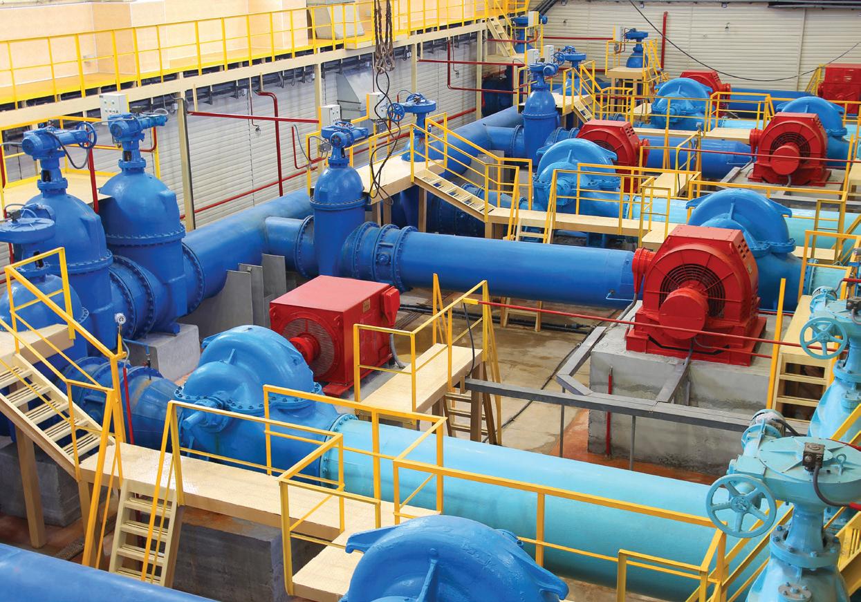
The mining factor
According to our respondents, the collapse in commodities prices and subsequent downturn in the mining industry has had a major impact on the pump industry. Almost 66 per cent of respondents said that in 2015, the volume of work for their business from the mining industry had ‘decreased’ or ‘decreased significantly’. For 21 per cent, their workload from the mining industry remained the same; and just 13 per cent reported an ‘increase’ or ‘significant increase’ in their volume of work from the mining industry.
The extent to which businesses are hurting as a result of this downturn varies considerably. Responses ranged from “Massively” to “The impact hit three years ago and has stayed flat since” to “Our resellers have
experienced negative growth in this sector, hence our sales have been impacted” and “Hard – thanks to our useless government’s inability to warn us about it.”
One of our hardest-hit respondents noted, “With a 60 per cent downturn in business, we’ve had to take severe action to reduce overheads...we’re in survival mode and are endeavouring to enter new markets. Unfortunately, most markets seem tough and there is a fight to the bottom going on.”
The ripple effect of the mining downturn has also been felt further afield than just companies working in the sector. “Although we only deal with the mines to a small degree, industry as a whole is affected, which has a ripple effect on us,” noted one respondent. This was a common sentiment from
companies not involved in the mining industry – while they themselves haven’t been affected by the downturn, companies in the mining space have been driven into their sectors, increasing competition. “The downturn has driven mining pump suppliers into our traditional markets, and this will keep impacting us in 2016,” noted another.
One bright spot in the mining industry which several respondents commented on was the increase in repair and maintenance works being provided to the industry. In an environment where capital budgets have been cut, it makes sense that the aftermarket would record growth for the pump sector, as companies seek to maximise the performance and extend the life of existing equipment.
Noted one respondent, “Upgrades
34 pump industry | Summer 2016 | Issue 14 www.pumpindustry.com.au STATE OF THE INDUSTRY
The water and wastewater industries are poised to provide growth to the pump industry players in this space.
in mine sites have significantly reduced, however, maintenance and repairs are keeping the business stable in 2015.” Added another, “Capital sales have slowed greatly, however pump service work has grown.”
Also looking for the silver lining was our respondent who noted, “The downturn and need for cost savings will help remove incumbent pumps, which will help us install more of our next generation pumping equipment.”
Further at the other end of the spectrum were the companies who reported that the back half of 2015 had provided a stabilising effect for mining supplies.
“We have picked up our figures in the last six months,” noted one respondent. “If anything we are struggling to keep up with demand in mining currently.”
This respondent reflected the overall attitude of respondents towards the mining industry, with 41 per cent expecting the mining industry to be a key driver of growth for the pump industry in 2016.
Ripple effects
Some of the ripple effects from the mining downturn - including the decreased value of the Aussie dollarare also impacting the Australian pump industry.
The drop in the dollar’s value is hitting importers the hardest, with several noting that as a result it is becoming a lot more expensive for them to import equipment, with the result being decreased margins, increased costs for customers (challenging in a low capex environment) or a combination of both.
A lack of work in the mining sector is also impacting the oil and gas industry, which in 2015 has faced the challenge of losing some of its largest customers. As a result, four of Australia’s refineries have now shut their doors, having flow on effects for the pump companies supplying those plants.
With Queensland’s CSG to LNG industry now effectively operational, supply work to this market has slowed down. Repair and maintenance work should provide a line of business to some, although this shouldn’t pick up for a few years yet.
Our respondents also believe that challenges in the mining sector have
dented confidence, particularly within governments, to greenlight major projects, a traditional source of work for many in the pump industry.
The one bright spot in the area of major projects and construction remains in the housing market, where growth has been sustained in 2015 – and this is expected to continue in 2016. A steady stream of new housing estates in the major metropolitan regions (Sydney, Melbourne and Brisbane), as well as the development and redevelopment of residential areas closer to CBDs, is providing a relatively steady stream of work to companies serving these markets.
Agriculture, water, wastewater: where you need to be now
While times have been tough for those impacted by mining, commodities prices and the Aussie dollar, our respondents working in areas like agriculture and irrigation, and water and wastewater have had a solid 2015 and are expecting further improvement in 2016.
As parts of Australia enter their third year of drought conditions, operators working in the irrigation sector have received a boost to their businesses, as farmers turn to irrigation systems to water their crops with ground or bore water. The El Nino conditions
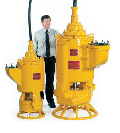
A TRIAL ON YOUR MOST DEMANDING SLURRY APPLICATION
Goodwin Submersible Pumps are recognised globally for their unrivalled heavy duty performance. The Australian pump industry has been taken by storm by the Goodwin precision engineered slurry pump, outclassing the competition with its strength and endurance, energy cost savings over the life of the pump, as well as reduced labour and maintenance costs.
The Goodwin Submersible Pump also has exponentially better performance than its competitors;
• Able to pump slurries of up to sg 2.8
• True dry run feature and
• Submergence depth of 28m
Located in Brisbane, Perth and Sydney we service Australia nationwide. Our fully trained technicians are available to assist with commissioning and installation, as well as provide ancillary products to assist with your pumping needs. The
Slurry Pumps
For further information & a Submersible Pump Trial... Call +61 (0)7 3205 7860
www.pumpindustry.com.au pump industry | Summer 2016 | Issue 14 35 STATE OF THE INDUSTRY
technical expertise of
Submersible Pumps has been proven in the steel,
and mining industries - pumps are now sold on five continents with centres of excellence in Europe, India, China, Brazil, South
and now Australia.
www.goodwinaustralia.com.au
for the most demanding environments
Goodwin
power
Africa
Submersible

currently affecting the country - which are expected to continue into 2016 - are likely to continue to support businesses in the irrigation space in the year to come.
“Sales of irrigation equipment due to drought has been the single biggest
factor affecting our business in 2016,” said one respondent. Added another, “Farmers being allowed to use more irrigated water has had a positive impact on our business.” Respondents are expecting this to continue into 2016, with one respondent predicting “More
REDEFINING THE FLAP VALVE PUMP

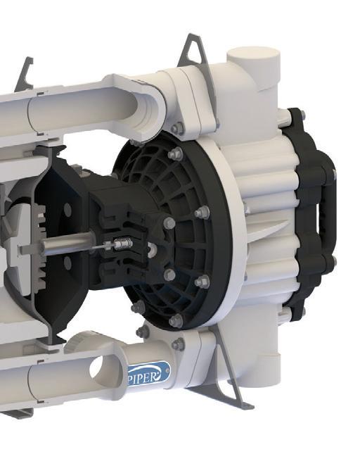


deep irrigation bores and on farm recycling pumps will be installed due to reduced surface water supplies in 2016.”
Equally important to our respondents in 2016 is the impact the water and wastewater sectors are going to have on their business. Noted one respondent, “As populations increase so does demand for water and wastewater plants, as well as infrastructure and residential buildings, all of which should provide good opportunities for companies in the Australian pump industry.”
Another respondent noted that “The need for water savings will also play a massive role in years to come, with better reliability required from pump sealing technologies.”
Other respondents focused on the aftermarket as a key growth area: “With the whole market being more opex driven, the opportunities will be on the service side of the pump businesses.”
Where to now?
Energy efficiency continues to loom as a key growth area for our respondents. Our respondents are now beginning to identify the need for better efficiency in pumps as a key business opportunity. “Energy consumption of pumping systems will be a key opportunity area, with an emphasis on reducing operating costs versus capital cost,” said one respondent.
Added another, “Efficiency is a major factor, and we can see this trend, so optimisation of existing plant, as well as new more efficient pumps and systems are the way to go.”
While it’s been another challenging year for the industry, there have been glimpses of hope, and importantly, there’s key growth areas the smart players in the game can turn their attention too.


Adapting and diversifying will be the keys to success in 2016.
36 pump industry | Summer 2016 | Issue 14 www.pumpindustry.com.au STATE OF THE INDUSTRY
SANDPIPERPUMP.COM/HDF2NM All Bolted Construction Leak free design. Bottom Discharge Gravity assist is ideal for pumping liquids with settling solids. Flap Check Valves Performance & solids handling. ESADS+Plus Air Valve Externally Serviceable Air Distribution System. Solids Range Up to 1.8” (46mm). Superior Dry Prime Up to 20’ (6.1 m) of water. The new 2” Heavy Duty Non-Metallic Flap Valve Pump has been designed to solve the most common problems in mine dewatering, sump, and chemical transfer applications. Lightweight & Portable At 53 lbs (24 kg) it is safely and easily transported.
Call Kelair for more information or to arrange a demonstration Phone 1300 789 466 www.kelairpumps.com.au
DANGERS IN BOTTOM LINE FOCUS
One of the biggest challenges our respondents are facing in this low-cost environment is the shift in customer thinking it has created, with many respondents noting that their customers are more focused on the bottom line than anything else when considering their pump purchased. Comments from respondents included:
• Customers have no interest in exploring opportunities, they just want to save money
• They want to reduce every transaction to the lowest common denominator
• There’s little cash flow available and this is unlikely to change
• Customers are and will continue to demand products for cheaper price – quality is moving down the decision making process
• More and more pumps are being ‘run to fail’ rather than having proactive maintenance programs
• Customers have become very price driven and are disregarding quality
• Customers see little to no value in technical expertise and backup, and simply buy based on price
One respondent summed up the issue well when they said “Many end users have limited expenses to only necessary items. Purchasing for improvements, efficiency gains and total life cycle cost, are being deemed ‘nice to have’, and quotes for such products have been rejected.”
Also frustrating the industry is the fact that many customers, in the quest for the lowest price, are turning to imported products – which often don’t stand up to locally made or quality imported products.
“We’re seeing more internet sales and increased Asian brand imports,” noted one respondent. Another added, “Although the quality appears to be slowly improving,the poor quality pumps coming out of countries such as China ultimately make a technician’s life very difficult in the field.”
According to another respondent, “The low quality products flooding the market are driving the high quality manufacturers to cheapen their offerings, reducing their own quality in order to remain viable.”
For customers that are sticking with their traditional suppliers, respondents say they are finding their customers to be non-committal and capital expenditure wary. Noted one, “Customers are much slower to make decisions, and I’m finding we have many more engineers creating enquiries just to appear active.” Another agreed, even adding, “Customers are taking longer to make decisions –and then often they make the wrong ones!”
The caution in utilising funds is also resulting in a tendency to delay the maintenance of existing assets. Noted one respondent, “Customers are, more and more, running assets to destruction.”



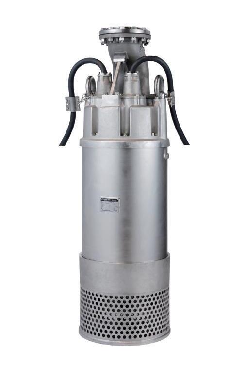
www.pumpindustry.com.au pump industry | Summer 2016 | Issue 14 37 STATE OF THE INDUSTRY
Analyst weighs in
To add another perspective to our State of the Industry analysis, we spoke to Ivan Fernandez, the Industry Director at Frost & Sullivan’s Industry practice in Sydney.
Like our industry respondents, Mr Fernandez notes that it has been a challenging 12 months for the pump industry – however, he does see light at the end of the tunnel, particularly for businesses established to assist with aftermarket services.
“The single biggest positive trend for the industry in 2016 will be in the area of aftermarket servicing,” said Mr Fernandez. “Continued weak macroeconomic conditions will prompt pump users to service rather than replace their equipment. This, combined with the fact that businesses will be able to realise substantial energy savings through regular servicing, will provide the aftermarket with a steady stream of work in 2016.”
Budgetary constraints will however continue to be an issue in 2016, but according to Mr Fernandez, even more challenging is the lack of insight the industry will continue to face from end users.
“There is a lack of awareness amongst a number of pump end users in relation to optimal pump service frequency, and the benefits that can be realised as a result,” he noted. Continuing to educate end users
about their pumps and their optimum operating conditions will a key area for pump professionals to focus on.
For companies supplying and manufacturing equipment, there will be challenges in two key areas: a greater need for fixed pricing; combined with a desire for increasingly sophisticated technologies.
“In the current climate, there is a need for longer term spare parts pricing and fixed price repair arrangements to improve accuracy of operations and maintenance budget forecasts,” noted Mr Fernandez.
“The industry will also face increased demand for advanced control technology for easier operational control, monitoring and remote management; especially for condition monitoring systems and other related diagnostic tools.
“These trends will put pump service providers under increased pressure in relation to price and delivery of valueadded services.”
Like the respondents in our own survey, Mr Fernandez believes that growth for the pump industry will come from sectors such as water, wastewater and construction (both
residential and commercial). He also forecasts some improvement for the mining sector in 2016 which is good news for the pump industry.
For companies seeking out new opportunities, Mr Fernandez has clear advice.
“Opportunities for the pump industry exist in the area of value-added services, such as condition monitoring, asset management,advanced diagnostics, smart pumping and optimisation.
“Over the next 12 months, educating customers will be critical. There will be an increase in the number of end users encouraged to develop their own in-house service teams, thus impacting outsourced revenue opportunities; and their will be indirect competition from engineer, procure, construct contractors, niche engineering support companies and service providers for related equipment.”
The smart companies will act now to figure out how they will mitigate these challenges and position themselves as ‘need to have’ rather than ‘nice to have’ provider in the current marketplace.


38 pump industry | Summer 2016 | Issue 14 www.pumpindustry.com.au
STATE OF THE INDUSTRY
52 Woodlands Drive, Braeside Victoria 3195 PO Box 876, Braeside Victoria 3195 Tel: (03) 9588 6900 Fax: (03) 9588 6999 Email: info@lkdiesel.com.au Web: www.lkdiesel.com.au •Petrol engines up to 13 HP •Diesel engines up to 83 HP •Generating sets up to 30 KVA We provide diesel engine solutions to EMPOWER your business Pump specifications Type BA150E D285 Max flow 430 m3/hour max Max pressure 27 mwc Connections DN 150 (6”) Solids handling 80 mm Impeller type Semi-open impeller Priming system BBA MP50 Engine Perkins 404D-22 Canopy M10-23 Weight (net) 1600 kg Sound 61 dB(A) at 10m NEW BBA150E dewatering pump in stock 6” diesel driven, sound attenuated, vacuum assisted dewatering and sewage pump OTHER PUMPS AVAILABLE $35,700 FEBRUARY SPECIAL
Repair,
Re-Design
Ef ficiency Impr ovement
Reconditioning
Restor e Clear ances
Re- Engineering
P f T ti erfor mance Testing.
Services available include:
• Inspection and trouble-shooting
• Case build up and re-machining
• Aillitfid bi Axial split case facing and reboring
• Axial thrust balancing
• Shaft and bearing API 610 upgrades
• Mechanical Seal upgrades to API 682
• Bearing housing & back cover retrofit
• Lube system upgrades
• Composite Wear Parts
• Tighter clearances
• Hydraulic Re-Rating
• Ridtti Rapid prototyping
• Driver upgrades (MEPS compliance)
• Baseplateadaptors and rebuilding
• Custom Spare Parts
• Rotating Element balancing
• ASME & AS1210 qualified Welding
• Hydrostatic Testing
• Performance Testing
• FFT Vibration

vice


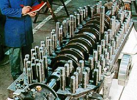


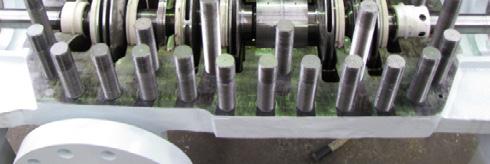
Centrifugal
Re-Manufactur e and
Ser
For ALL types of
Pumps
analysis A.B.N. 37 006 317 979 EMAIL unitedpumps@unitedpumps.com.au http://www.unitedpumps.com.au/ 31 WESTERN AVENUE SUNSHINE, VICTORIA 3020 P.O. BOX 348, SUNSHINE, VICTORIA 3020 •PHONE +613 9312 6566 •FAX +613 9312 6371
Looking at the total piping system
by Ray Hardee, Chief Engineer, Engineered Software
In the first of a regular series of columns on overall piping systems, Ray Hardee discusses how the various elements making up a total pumped system work together to meet system requirement.
Pumped systems can be classified as either process systems, in which a product is made, or support systems, in which a service is supplied. Figure 1 is an example of a process system in which a fluid is pumped through a process to make a final or intermediate product. In this example we have a process fluid that is pumped from a supply tank, through a heat exchanger, a control valve and then into a distillation tower. Systems like this are often found in refineries and chemical plants.
Figure 2 is an example of a support systems that provides cooling water to equipment within a plant. Here we have a cooling water system that removes waste heat from equipment or plant processes. We also have a pump that circulates water from a cooling tower basin, through multiple parallel circuits where the cooling water removes excess heat from the equipment, flows through a control valve, then back to the cooling tower where the excess heat is removed by evaporation of some of the cooling water.
Elements of a pumped system
Piping systems are composed of many pieces, so at first glance, it may seem difficult to understand its operation. If we can look at each item, then identify its function, we can start to make sense of the system and its interconnections.
All equipment found in pumped systems fall into three basic elements: pump elements, process elements and control elements. These elements work together so the system can meet its design requirements.
• The pump elements include the pump, the drive adding energy to the pump, pump seals and other support systems for the pump and drive.
• The process elements include the supply and destination tanks, the interconnecting pipelines and the process equipment found in Figures 1 and 2.
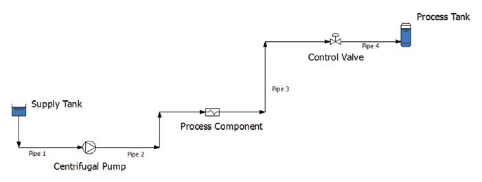
• The control elements include the control valve and plant instrumentation to control the process variable and safely operate the system.
Every pumped system, regardless of its size or complexity, is made of these three basic elements so the system can meet its design objectives.
Function of each element
Now that we know the three elements found in every pumped system it’s time to discuss their function within the system. We’ll start out with the pump elements.
The pump elements supply all the fluid energy to the system required by the process or the service. The drive takes external energy (electricity for a motor or steam for a turbine) and converts it to mechanical energy to the pump shaft. The rotating pump shaft drives the impeller which converts the mechanical energy to kinetic energy. The pump impeller and casing are used to convert the kinetic energy to fluid energy, referred to as head, to move the process fluid through the pumped system.
The process elements consist of tanks and vessels making up the boundary of our piping systems, the pipelines to transport the process fluid through the system and the process element to meet the system objectives.
For example the purpose of the system presented in Figure 1 is to provide heated process fluid to the process tank prior to going on in the system.
The control elements consist of the instrumentation, control loop/s and control valves needed to improve the quality of the product. For example, the system is designed to provide a quantity of fluid to the process tank at a specific temperature. If the temperature control loop does not maintain the fluid temperature into the process tank distillation the process will not operate efficiently. It is important to remember that the energy added in the heat exchanger is thermal energy and does not affect the hydraulic energy added to the system by the pump.
Considering the usage of energy for moving the fluid in the piping system, the energy supplied by the pump is used by the process elements and the control elements, and it can be reduced to the following formula, which shows the relationship of the energy supplied by the pump and the energy used in the system:
hpump=hprocess+hcontrol
In the formula the value h is in meters of fluid. Measuring fluid energy in meters of fluid is customary when working in pumped system, as a result all the examples presented in this column will list fluid energy in meters of process fluid.
40 pump industry | Summer 2016 | Issue 14 www.pumpindustry.com.au
PUMP SYSTEMS
Figure 1. An example of a process system in which the fluid passes through the system to make a product.
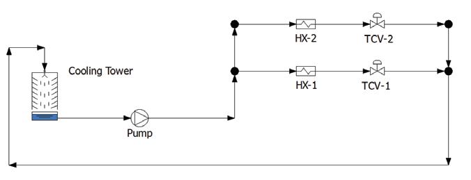
Figure 2. An example of a support system in which a fluid is recirculated in the system to provide cooling water to various plant loads.
Conclusion
In this introduction we grouped the elements found in every pumped system and the purpose of these elements. We also saw how the energy
supplied to the system by the pump is used by the process elements and control elements to make a product and improve its quality.
In future articles we will look at typical problems associated with real life piping
systems, develop troubleshooting skills to identify the problem and determine the possible solutions. In the next issue of Pump Industry we will look at a system that is unable to meet an increased flow requirement and what can be done to correct the system.
In my experience, the best way to demonstrate a point is with examples. I like to provide real life examples to build troubleshooting skills in my columns. I have accumulated a variety of examples of pumped systems experiencing problems, but one thing I have learned is that I haven’t seen them all. That’s where you come in. If you have or are experiencing a problem within a pumped system, let me know and we’ll troubleshoot it together and then share the results with other readers.
Ray Hardee is a registered professional engineer in the United States, with more than 45 years experience in operating, starting and designing fluid piping systems. He is also one of the principal founders of Engineered Software, Inc, a company which develops software and training services for fluid piping systems. The company developed the PUMP-FLO program which is used by over 117 pump manufacturers worldwide for the selection of centrifugal pumps. For more information about Ray or his company, head to www.eng-software.com.



www.pumpindustry.com.au pump industry | Summer 2016 | Issue 14 41 PUMP SYSTEMS VARIABLE SPEED DRIVE AND SOFT STARTER REPAIRS Save $ Repair your drive NO Site modifications NO Reprogramming NO Drive commissioning NO Document updates NO Retraining No OEM support? - Discontinued model? - Spike damage? ALLEN BRADLEY, DANFOSS, ABB, ITT/LOWARA, PDL All drives undergo a health assessment and restoration during repair and overhaul for confidence 20 YEARS OF EXPERIENCE SPECIAL ITT Lowara Hydrovar – overhauls 2kW – 4kW Gen 3: $560 + GST Gen 4 : $450 + GST Includes interface, functional and load testing 2 year parts and labour warranty for the complete drive. Integra Drive & Automation Services 0467 231 121 WWW.INTEGRAAUTOMATION.COM.AU Automation and instrumentation repairs | EMC compliance assessments | On site system troubleshooting
The dos and don’ts of pumping fuel oil
by Chad Wunderlich, Engineering Manager – Technical Customer Service, Viking Pump
Though the handling of fuel oils is not necessarily challenging, the reliable handling of fuel oils is a complex matter, critical for heating and transportation systems. A contributing factor to the complexity of handling fuel oils is the wide range of application details for the various fuel oils:
Capacities 0.1GPM (0.02m3/hr) to 1,000+GPM (230+m3/hr)
Pressures 25PSI (1.75BAR) to 250PSI (17.5BAR)
Viscosities 30SSU (1cSt) to 7,500SSU (1,650cSt)
Temperatures Ambient outdoor to 250°F (120°C)
These variances from application to application result in a wide range of pump constructions and drives. Despite these variances, there are some common guidelines to follow to ensure smooth operation and long pump life.
Rotary pumps are an excellent means of loading and unloading, transferring, and circulating fuels. These pumps can be used with fuel oils including diesel fuel, heavy oils, crude oil, gasoline, kerosene, jet fuel and LP Gas.
Dos and don’ts
Pumping at slower speeds and lower pressures; and using materials designed for the anticipated temperature, will pay off in longer, trouble-free service, even if oil properties vary from those originally anticipated.
The key things to do when pumping fuel oils include:
• Install the pump as close as possible to the supply tank
• Leave working space around the pumping unit
• Use large, short, and straight suction piping; ‘short and fat’ pipes are excellent
• Install a strainer in the suction line
• Double-check alignment after the unit is mounted and the piping is hooked up
• Provide overpressure protection for the discharge side of the pump, either in-line or on the pump
• Extend service life with preventive
maintenance procedures such as periodic lubrication, adjustment of end clearance, and examination of internal parts
• Obtain, read, and keep the maintenance instructions furnished with your pump, drive, and other system equipment.
Conversely, when pumping fuel oils, do not:
• Run a pump at faster than approved speeds
• Run a pump at higher than approved pressures
• Run a pump at higher than approved temperatures
• Use extra large, extra long suction line with a suction lift.
Installing a vacuum gauge and a pressure gauge on or near the pump will also help lengthen service life. Gauges provide a window into what is happening inside the pumping system. Properly interpreted readings can give clues to the nature of many problems. Longterm readings will show gradual changes taking place within the system.
Given the availability of certain fuels at any particular time, many fuel oil systems now accommodate various fuels (No 2 through to No 6 fuel oil, for example). Each fuel oil differs slightly in properties and these differences place unique demands on the system. Be sure to discuss these differences with your pump/system supplier.
Handling crude oil
Crude oil is a naturally occurring liquid found in formations of the earth. It is typically extracted by large reciprocating pumps called pump jacks. Crude oil is then refined into fuels such as gasoline, diesel, kerosene, and other fuel oils. Characteristics such as color and viscosity vary from site to site, but typically fall into the following ranges:
Wyoming, Montana
California
Pennsylvania
(4-170 cSt) at 60°F (15°C)
34-210 SSU (2.5-45 cSt) at 100°F (38°C)
75-1,200 SSU (15-250 cSt) at 60°F (15°C)
45-300 SSU (5.5-65 cSt) at 100°F (38°C)
40-4,800 SSU (4-1,050 cSt) at 60°F (15°C)
34-700 SSU (2.5-150 cSt) at 100°F (38°C)
45-200 SSU (5.5-40 cSt) at 60°F (15°C)
38-90 SSU (3.5-18 cSt) at 100°F (38°C)
Due to crude oil’s high viscosity and wide range of application conditions, rotary pumps are well suited to handling crude oil. Rotary pumps are used for transport, refining, pipeline injection, and for high working pressure pipeline sampling applications. While compatible with cast iron, pumps for refinery and pipeline sampling applications are typically steel. Pump construction will depend on the particular oil and application.
Many crude oils contain dirt, sand, and other particulate prior to refining. Often pumps for dirty crude oil are supplied with hardened parts to prevent the particulate from damaging the pump.
Handling gasoline and light fuel oils
Light oils such as gasoline, kerosene, and jet fuels have low boiling points and as such, are the first to be distilled off from crude oil. They are used primarily as fuels. All are fairly easy to handle, but are thin (29-35SSU/0.9-2.5cSt), non-lubricating, and have high vapor pressures. Lifts (when the pump port is above the liquid level in the supply tank) should be kept to six feet or less to prevent vapourising the liquid at the pump inlet. Be sure to check the system net positive suction head (NPSH) to make sure it’s adequate.
Handling No 2 and 6 fuel oils
Fuel oils in the United States have six classifications based on their boiling points, composition, and purpose. Fuel oils No 2 and 6 are most commonly
42 pump industry | Summer 2016 | Issue 14 www.pumpindustry.com.au
Viscosity Texas, Oklahoma 40-780 SSU
Location
OIL & GAS
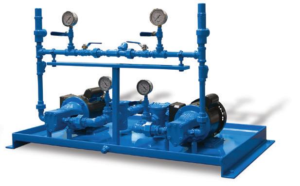
used. No 2 fuel oil is used for truck fuel, heating, and power generation. No 6 fuel oil is used for ship fuel (commonly referred to as Bunker C oil), heating (though usually reserved for larger buildings), and power generation. Typical application conditions for handling fuel oils are as follows:
Viscosity
No 2 fuel oil ranges from 2.5 to 7cSt (35 to 50SSU), but may get even thicker at temperatures below freezing because of congealing wax. No 6 fuel oil ranges from 20 to 1,650cSt (100 to 7,500SSU) in the normal handling temperature
range, but may vary widely depending on the source of the oil, sulfur content, and blend.
Normal handling temperatures
No 2 fuel oil is typically handled in the range of -20° to 100°F (-30° to 38°C). No 6 fuel oil is typically handled above 100°F (38°C) to reduce the viscosity for ease of handling.
Unheated, buried tanks with two or more feet of ground cover will normally stay within a range of 40° to 70°F (4.5° to 21°C), depending on locale and time of year.
Lift should be kept to a minimum.

Repairs To All Makes Of Pumps & Seals
Full Line Mechancial Seal Manufacturer & Supplier
Australian distributor for Hi-Fab Seals
Australian distributor for Prochem Chemical Pumps
All Seal & Pump Spares
Seal Testing
Submersible Pump & Seal Spares & Repairs On Site Evaluation
Site Surveys
Full Pump Repair Service
Pump Base Fabrication
Steam Turbine Repairs On Site Monitoring
Troubleshooting
Reliability Improvement


For No 2 fuel oil, the vacuum reading at the pump should not exceed 15”Hg under the worst conditions. Lifts should be kept to under ten feet and may be even less depending on suction piping length, fittings, and priming conditions. The vapor pressure of No 2 fuel oil is less than 0.1PSI (0.0069BAR) at ambient temperatures. If the vacuum at the pump exceeds 15”Hg, entrained air in the oil may cause capacity and noise problems. Under vacuum conditions the air will expand and the pump will not deliver its full capacity of oil. While the rotary pumps are self priming, a


www.pumpindustry.com.au pump industry | Summer 2016 | Issue 14 43 OIL & GAS Recycle your Pumps & Seals Total Pump Upgrade, Re-build, New Cartridge Seal, Bearing Protectors, Installation, Laser Alignment
Chemical
Worthington 10LN Re-build
Prochem
Pumps
Repairs to all makes & models Split Seal Repairs Two fully equipped workshops for all your pump & seal repairs, machining and engineering needs. Brisbane, 24-26 Neumann Road Capalaba 4157. Ph: (07) 3245 6587 F: (07) 3245 6586 www.rathboneengineering.com.au
Hi Fab Seals
Repairs
18 Malduf Street Chinchilla 4413. Ph:
E:
Submersible
Surat Basin,
(07) 4665 5355 F: (07) 4665 5356
lance@rbsealing.com.au
Discharge Header
Header Basket Strainers Motors Check Valves UL-343 listed External Gear Pumps
Suction
Figure 1.Duplex fuel oil skid for delivering No 2 fuel oil built by Viking Pump.
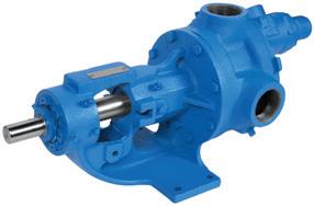
foot valve is typically recommended to minimize the chance for losing suction.
For No 6 fuel oil under the worst conditions (i.e. highest viscosity and lowest liquid level), position the pump and select pipe and fitting size to give vacuum readings of 15”Hg or less. The viscosity of No 6 Fuel Oil varies from one tank car load to the next. Some tank cars contain ‘light ends’ which affect viscosity and may cause lift problems.
For systems to handle No 2 or No 6 fuel oil, designing a system to handle either liquid presents problems in sizing the suction lift, fittings, and strainer.
Large rotary pumps are often used in the refining process of fuel oil as well as for transport and delivery. Upon delivery, smaller rotary pumps takeover (usually 30 GPM and smaller), often assembled
as a duplex pump system complete with drive equipment, strainers, valves, and controls (see Figure 1). These duplex systems insure continuous oil delivery to critical applications such as:
• Fuel supply to diesel generators used for backup power
• Transferring fuel from storage tanks to smaller day tanks
• Boosting low pressure fuel oil to burner pressure on oil-fired furnaces
• Recirculation oil filtration system to ensure clean and/or water-free oil.
Depending on the service and system location, these pumps may require special construction and testing (i.e. pumps which are UL-343 listed for fuel oil service).
Handling LP gas
Propane is normally a gas, but is compressible to keep in its liquid state for storage and transport. LP gas is used for heating, as a cooking fuel for barbeques and portable stoves, and as fuel in some vehicles such as buses, locomotives, and fork lifts.
Rotary pumps are used for bulk plant transfer service, truck unloading, and
bottle filling. Due to the high working pressure, high vapor pressure, and extremely low viscosity, LP gas pumps require special construction (Figure 2).
Due to the high vapour pressure, NPSH must not be overlooked. Placing the pump too far from the supply tank, allowing the LP gas to get too hot, or running the pump too fast may lead to cavitation, which in turn will lead to noise, reduced capacity, and reduced pump life. The LP gas pump in Figure 1 features a return-to-tank pressure relief valve. This valve allows the LP gas to flow back to the supply tank when the discharge valve is closed, rather than cycling the gas through the pump. By doing so, less heat is imparted to the LP gas and the gas is not allowed to boil in the pump.
Before selecting a pump for fuel it’s important to speak with the pump/system representatives to address all aspects of the application. Seal selection, drive sizing, and NPSH must all be addressed to insure years of reliable fuel handling.
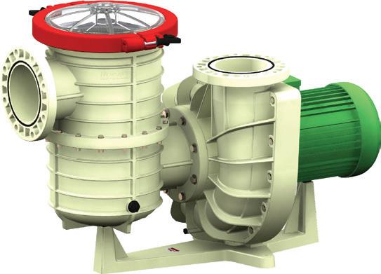
44 pump industry | Summer 2016 | Issue 14 www.pumpindustry.com.au
Aquaculture, Sea Water & Chlorinated Water Corrosion-free Pum P ing Lightweight Quiet Thermoplastic up to 45kW PH +61 7 3057 5861 FAX +61 7 3806 4528 info@actionaquatics.com.au European Nozbart Thermoplastic pump (Tsunami Series
45kW) Action Aquatics - Half Page.indd 2 12/11/2015 11:07 PM OIL & GAS
Figure 2. Image of a UL-51 listed Rotary Internal Gear Pump for handling LP gas.
up to
Getting out of hot water
If you need reliable and efficient pumps to move hot and viscous fluids; If you need to move hot oils as high as 400°C, or hot water up to 207°C; If you need these pumps to save you money while they’re pumping; Then Pump Power Australia has just what you need with their complete range of German Allweiler ALLHEAT® Pumps.
Pump Power Australia is proud to be the exclusive Australian supplier of Allweiler ALLHEAT® pumps for over 20 years and is proud to be partnered with a manufacturer that specialises in such superior product design, engineering and precision. The ALLHEAT® range of pumps is just one of the many ranges of industrial pumps which Allweiler produces.
Allweiler began developing thermal oil pumps back in 1960. Since that time, they have produced and delivered several hundred thousand pumps for heatcarrier applications and now have a global market share of around 25 per cent, which is growing. Allweiler is one of the industry’s major players, with their heatcarrier pumps being used successfully in every industrialised country of the world.
When you choose a heat-carrier pump from Allweiler, you are choosing from a manufacturer widely experienced in designing and optimising for real-world applications.
For every heat-carrier and every pumping task
Allweiler produces its own pump units and complete pump packages for virtually every requirement related to heat transfer. This includes mineralbased, synthetic as well as hot water applications. ALLHEAT® pumps are not only universally suitable for all heatcarrier liquids, they are engineered to not leak, to not give under pressure and to be completely safe for the operator when used according to instruction, unlike many cheaper versions from
other manufacturers.
The magnetic drive option, ALLMAG®, are 100 per cent hermetically sealed, so they meet the most stringent environmental requirements. They can safely move toxic, environmentally hazardous and odorous heat carrier liquids without spillage or seizing up. With process, block, and inline versions, these pumps can be easily adapted to the installation conditions at your plant.
Service and support guaranteed
If you decide to use an ALLHEAT® pump, you can count on service and support no matter where you are located. Pump Power Australia stocks a complete range of Allweiler pumps and spare parts for prompt delivery.
Allweiler pumps are available in Australia through Pump Power Australia. For more information, visit www.pumppower.com.au or call 03 9933 7400.
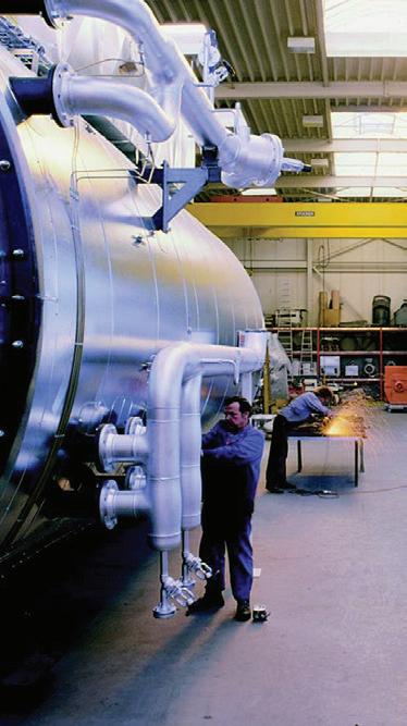
Allweiler ALLHEAT® Pumps
Suitable for virtually every requirement related to heat transfer, including both mineralbased as well as synthetic heat carrier oils and hot water.
• Great quality and great prices
• Proven long term reputation and reliability
• German precision & engineering
• Long life & low maintenance
• Safe operation
• Special pricing for OEM’s
• Pumps and parts in stock now
• Only available from Pump Power Australia
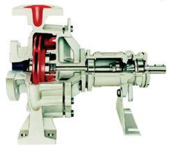
Please call or email us for a quotation



www.pumpindustry.com.au pump industry | Summer 2016 | Issue 14 45 OIL & GAS | PARTNER SOLUTIONS
on a wide range of pumps, services or spare parts Pump Power Australia Pty Ltd 9 Export Drive, Brooklyn VIC 3012 P: 03 9933 7400 F: 03 9315 1345 E: sales@pumppower.com.au The BEST SOLUTION for HOT
OIL & WATER applications

The pump industry relies on expertise from a large and varied range of specialists, from experts in particular pump types to those with an intimate understanding of pump reliability; and from researchers who delve into the particulars of pump curves to experts in pump efficiency. To draw upon the wealth of expert knowledge the Australian pump industry has to offer, Pump Industry has established a panel of experts to answer all your pumping questions.

Progressive cavity pumps
Our progressive cavity pump expert is Peter Vila, Managing Director of SEEPEX Australia.
Peter has been involved with pumps for 35 years. He spent the first five years repairing them and the subsequent 30 years directly in technical sales, and for the past 15 years he has been predominately involved with SEEPEX progressive cavity pumps.
We don’t seem to hear a great deal about progressive cavity pumps being used for applications within the oil and gas sector. Is this because they are not particularly suited to oil and gas duties?
Actually, the complete opposite is the case, with many oil and gas duties being successfully met by a vast array of progressive cavity (PC) pump models. Applying PC pump technology correctly to the application is crucial for reliable
in-service performance. Care must be taken to understand the needs of particular applications, in order to apply correct designs, within what are typically complex systems. Understanding how different equipment interacts can be the difference between failure and success.
In addition to highlighting examples of typical PC pump applications within the oil and gas sector, here is a summary of some key considerations when contemplating the use of progressive cavity pumps for these applications.
Low shear
Gentle low-shear pumping action. Oil and water mixtures generally must be transported with minimal damage to the oil droplet size, to minimize risk of creating emulsions that are difficult to separate. The Society of Petroleum Engineers (SPE) paper 18204 confirms that progressive cavity pumps are the best pump technology for oil/water separation.
Self-priming and no gas locking
Excellent self-priming characteristics and suction lift capabilities, even on gaseous liquids, up to 9m (29.5ft.).
Handling of multi-phase products
Oil, water and gas can be transported
reliably by uniquely configured progressive cavity pumps, with control systems to deal with variable flow requirements. PC pumps can be configured to handle up to 99 per cent gas content.
Solids handling
Progressive cavity pumps handle products with entrained solids. Drill cuttings and sand, for example, are handled with low internal velocities.
Low NPSH requirements
The NPSH requirement of progressive cavity pumps can be as low as 0.3m (0.98ft.). This is ideal for liquids with elevated temperatures and high vapour pressures.
Viscosity is not a limitation
From low viscosity condensates to heavily dewatered, oily sludge cake, progressive cavity pumps can handle the challenge. With open hopper designs, non-flowable products are efficiently fed into the rotor/stator pumping elements.
Stable and variable flow
Progressive cavity pumps deliver accurate metered flow with every revolution of the rotor. Flow rate variation is minimal, even across broad
46 pump industry | Summer 2016 | Issue 14 www.pumpindustry.com.au ASK AN EXPERT
pressure ranges. Flow rates are directly proportional to pump speed.
Low pulsation
The flow from a progressive cavity pump has minimal pulsation, so there is no need for pulsation dampeners.
Versatile
Integration of progressive cavity pumps is generally quite easy – they can be installed horizontally, vertically, in a can or fully submerged, to fit virtually any available space. Also, depending upon the process requirements, pump flow is reversible.
High pressures
Progressive cavity pumps can have uniquely special universal-joint construction, meaning they can easily handle suction pressures up to 150 bar
(2175 psi) with both pin and cardan-type universal joints.
In summary, progressive cavity pumps can transport thin to highly viscous products with or without solids, at low to high temperatures, pumping gently and with minimal pulsation. They also feature excellent metering accuracy and can easily pump media such as produced water and chemical additives. Most progressive cavity pump manufacturers should be able to offer pumps which are engineered to meet the requirements of API 676. SEEPEX is certainly one of these manufacturers, having built progressive cavity pumps according to API 676 for more than 40 years.
For more information on progressive cavity pumps, please contact SEEPEX Australia (02) 4355 4500 or info.au@ seepex.com
Progressive cavity pumps have a wide range of applications across the oil and gas industry.











www.pumpindustry.com.au pump industry | Summer 2016 | Issue 14 47 ASK AN EXPERT
Selecting valves considerations by industry and application

Choosing the right valves
Classifying valves by the first parameter, motion, means looking at some distinct differences in valve design.
The types of valves appropriate for a particular system are heavily dependent on the specific application and the functions the valves will fulfill in the system. When selecting a valve for a given application a number of important factors must be taken into consideration. These include, but are not limited to:
The flow media – The nature of the fluid being pumped has a range of implications for the system and the type of valves appropriate. Fluid characteristics that must be taken into account include the flow properties of the media, whether it is corrosive or abrasive, and potential chemical reactivity with the materials from which the valve or other system components are made.
System pressure and temperature – Valves and the materials they are composed of must be capable of withstanding and operating effectively under the environmental conditions of the system, including high or low temperature and pressure extremes.
Application and function – Depending on the requirements of your system valves may be required to fulfill various functions. Different types of valves will be more capable of meeting the requirements of your application. For instance, does the valve only need to completely stop or start the flow, or should it also play a regulatory or flow throttling role? How much leakage can be tolerated by the system? Is the valve required to release or regulate system pressure? How precisely must the valve be able to control the flow?
Cleaning and maintenance requirements – How easily can maintenance or cleaning activities be performed on the valves? How regularly must they take place to maintain performance?
Integration with other system components – The choice of valves must take the other instrumentation components and overall system design into consideration.
Other application specific criteria – Your particular application may have other specific requirements of valves and your industry may require valves to meet specific standards. For instance, in some applications strict hygiene criteria may apply which will affect the type of valves that can be used in a system. Safety standards may also dictate various
48 pump industry | Summer 2016 | Issue 14 www.pumpindustry.com.au
VALVES
Valves are vital components of pumping systems and pipelines in near-countless different industries. The functions valves fulfill in these systems can include stopping and starting flow, regulating the rate and direction of flow, preventing backflow, and regulating system pressure. While valves may sometimes be dismissed as secondary considerations when designing a pump system, choosing the right valves can have significant implications for the system’s performance, safety, efficiency and longevity.
by Michelle Goldsmith, Pump Industry Associate Editor
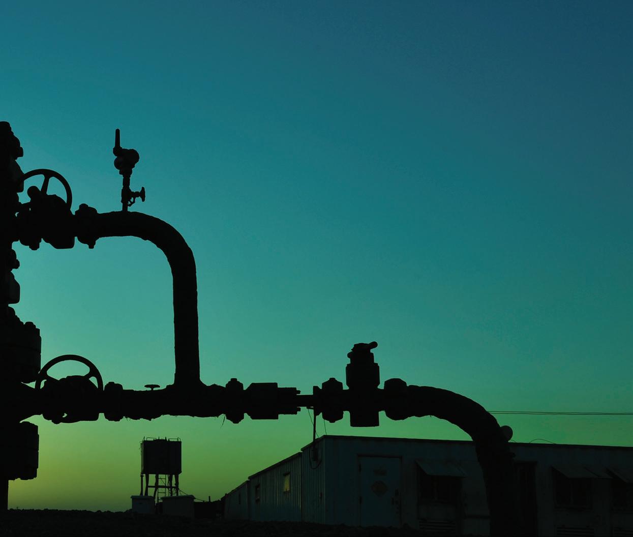
criteria for valves for particular applications. Noise level or firesafety requirements are also among the myriad factors that may come into play when choosing valves.
Classifying valves by control method and function
Valves are frequently classified by either the method of control they employ or the function they perform in a system. Methods of control include linear motion or rotary motion. Linear motion valves move components linearly (for instance, moving a disc, plug or diaphragm into or out of the flow passage) to stop, start or throttle the flow of fluid through the valve. These type of valves generally offer high accuracy and are more resistant to cavitation than rotary valves. On the other hand, rotary motion valves work by rotating closure elements (such as a disc or ellipse) about an angular or circular shaft across the diameter of the passage to impede the flow of fluid. Usually a 90°, or quarter-turn, will fully block the passage of fluid through the valve.
Valves can also be classified by their usual function. For instance, stop/start valves (alternatively known as on/off valves) either completely block or completely allow the flow of fluid. Although some can be used to throttle flow by turning them partway to the closed position, they are not designed
for this purpose and using them this way is not recommended. On the other hand, throttle or control valves are designed to throttle or regulate the speed of fluid flow and pressure of a system as well as being able to completely impede the flow when required.
Non-return valves are those which open or close depending on the direction of flow, to prevent backflow. Flow in one direction opens the valve while floe in the reverse direction closes it. Pressure release valves open slowly when system pressure becomes too high, releasing excess pressure to prevent system overpressurisation.
Here we will examine some of the most commonly used valve types, their method of operation and their functions.
Stop/start valves
• Gate valves (linear motion, stop/start function)
Gate valves (also known as sluice valves) operate via the use of a sliding part, or gate, that can be moved in or out of the path of the conveyed substance. This is particularly useful for straight-line flows and when you wish to isolate a particular area of a pipeline.
• Rotary ball valves (rotary motion, stop/start function)
Rotary ball valves utiliise a ball like structure containing
www.pumpindustry.com.au pump industry | Summer 2016 | Issue 14 49
VALVES
channels through which fluid may flow. To block the flow of fluid, the ball is rotated so that entry to the channels no longer matches up with the passage of the fluid.
• Plug valves (rotary motion, stop/start function) Plug valves make use of a rotating cylindrical or conically tapered plug containing passageways through which fluid may flow when the valve is open.
Throttle or flow control valves
• Diaphragm valves (linear motion, control/throttle function) Diaphragm valves, also known as membrane valves, involve a flexible diaphragm material connected to a compressor, which is moved up and down by the valve’s stem to open and close the valve, either completely or to various degrees. It is the diaphragm material and not the operating mechanism of the valve that is exposed to the media within the pipeline and therefore must be of appropriate material.
• Butterfly valves (rotary motion, control/throttle function) Butterfly valves utilise a disk-shaped rotary closing mechanism positioned in the centre of the pipe by a rod passing through it. This rod is connected to an actuator on the outside of the valve. Rotating the actuator rotates the disk, which can be turned face-on to the flow to completely block fluid from passing, at various angles to control flowrate, or completely parallel to allow for maximum flow rate.
• Globe valves (linear motion, control/throttle function) Globe valves are primarily used for modulating flow through a pipe system. They consist of a moveable disk shaped plug and a stationary ring seat. The plug is connected to a stem that is controlled on the outside of the valve and can be screwed into the seat to throttle the flow of fluid through the valve.
• Needle valves (linear motion, control/throttle function) Needle valves are primarily used to precisely regulate
flow in systems with low overall flow rates. These valves operate through the use of a small port and a tapered, needle-shaped plunger, which may be gradually retracted from its seat to allow more fluid to pass through.
• Squeeze valves (linear motion, control/throttle function) Squeeze valves are pressure-operated valves that may perform both on/off and flow modulating functions. They involve the use of a tubular cuff element that is squeezed together via mechanical, hydraulic or atmospheric pressure to block the flow of fluid through a system. To open the valve, the pressure is released and the cuff relaxes. Different levels of pressure can close the valve to various degrees to regulate the flow.
• Pinch valves (linear motion, control/throttle function) Pinch valves perform both on/off and flow regulating functions, often via direct contact to the process tubing of a system. The tubing is pinched shut to prevent flow through the valve. The sleeve may be pinched to varying degrees to modulate flow. Because no valve components (upon which material may become caught) contact the fluid being conveyed, pinch valves are particularly useful in hygienic applications.
Common additional valve considerations by industry
For certain industries there are some additional general criteria that are commonly considered when choosing valves. These, include, but are not limited to, those discussed below.
Pipeline industries
Valves used in large pipelines are often required to be piggable. In other words, when open, the valve bore must have a diameter that allows a pipeline pig to pass through to perform various maintenance, inspection and cleaning activities. Often these are full bore valves, with a bore size the same size as the rest of the pipeline when open. Often these are ball valves.






50 pump industry | Summer 2016 | Issue 14 www.pumpindustry.com.au VALVES
MILLENNIUM COUPLING COMPANY “WE WORK UNDER PRESSURE!” AUSTRALIA’S BROADEST RANGE OF HOSE COUPLINGS AND RELATED PRODUCTS PRICEONLINE & AVAILABILITY Free, Fast, Delivery anywhereinAustraliaonordersover$50excGST ANY COUPLING, ANYTIME, ANYWHERE www.mcc-ltd.com.au | 1300 853 250
Valves used in certain pipeline industries, such as the oil and gas industries, also often need to be able to be operated remotely and are frequently required to be able to deal with extreme environmental conditions. These may include extremely high temperatures and pressures or extremely low pressures and cryogenic temperatures, depending on application and the stage of the oil and gas production process.
Food and beverage industries
Food and beverage industries often have very strict hygiene standards to which they must adhere. This often means that valves which come into direct contact with food are required to meet very specific criteria such as not containing any rough surfaces, crevices or pores in which food materials and bacteria could accumulate. They must also be made of compliant materials that will not absorb material or degrade and contaminate the product. In some cases a valve type that does not come into contact with the product at all may be preferable.
Water and wastewater
Valves used in water and wastewater applications will need to conform to a number of criteria. The material from which valves are made is important for water and wastewater
treatment applications, as the valve must be able to withstand any chemicals it may come into contact with. Applications where the water may contain solids or stringy materials often require valves that are not vulnerable to clogging or material buildup, often ruling out certain valve types such as butterfly valves.
Chemicals and pharmaceuticals
Valves in the chemical and pharmaceutical industries must comply with strict safety standards dependent on the flow media. For instance, they must be made from materials that are non-reactive with any chemicals they will be exposed to and often must be able to handle abrasive or volatile materials. Extremes of temperature or pressure may also be experienced. Valves in these industries are often required to provide very accurate flow control and prevent leakage of potentially hazardous materials.
These are just some of the many considerations one must take into account while specifying valves for a system. While determining the right valves can be complicated, correct valve choice is vitally important for the overall efficient, safe, compliant and effective operation of a pumping system.
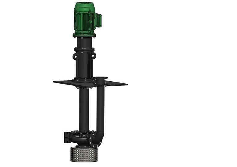
www.pumpindustry.com.au pump industry | Summer 2016 | Issue 14 51 VALVES Phone: 03 9793 7577 Web: asmpumps.com.au Email: sales@asmpumps.com.au No mechanical seals or bearings submerged in the liquid Can run dry indefinitely without damage Wide range of options to suit all applications Solids Handling & Clean water options available YOUR CUSTOM DESIGN PARTNERS OVER 50 YEARS EXPERIENCE NEVER HAVE A MECHANICAL SEAL FAILURE AGAIN WITH THE CANTILEVER COLUMN C SERIES PUMP RANGE
Check valve applications
by Neel Kaila, Director, Neel Pty Ltd
This article presents some conventional and innovative ways to apply check valves in hydraulic circuits. The author has successfully used all the configurations in various projects.
Check valves
A check valve, clack valve, non-return valve or one-way valve is a valve that normally allows fluid (liquid or gas) to flow through it in only one direction. A check valve is an electronic equivalent of a diode which permits the flow of electrical current in one direction only. The various practical applications of check valves are as follows.
• The check valve prevents the discharge tank back flowing into suction tank during pump stoppage.
Single pump systems
This is the most common application of a check valve where a check valve permits flow from suction tank to the discharge tank and prevents the reverse flow from the discharge tank back to the suction tank during pump stoppage or pump failure. Refer to Figure 1.
Series pumping systems
When pumps are connected in series especially when pumping fluids in cross country pipelines then it is recommended to place check valves in parallel to each pump. Under normal operation the discharge pressure of the pump will keep the check valve in closed position. However if any pump fails then the pressure drop across the pump will activate the check valve. This will split the flow in two streams and reduce the hydraulic losses. Refer to Figure 3.
Emergency cooling systems
This is a smart way of using check valves. Under normal operation only a small amount of fluid will go to the header tank and the same amount will overflow and drain back into the suction tank. So in effect the header tank will be always charged with water. The main flow will go through the load. The discharge pressure of pump will keep CV2 closed. When the pump fails CV2 opens and drains all the water via the load thereby saving critical equipment and allowing sufficient time for controls to take over. Refer to Figure 4.
Pressure relief systems
Parallel pump systems
This is another common application of check valves. In this configuration two or more pumps are connected in parallel. Refer to Figure 2. The check valve has two functions in such a scenario:
• The check valve prevents the duty pump, pumping into the standby pumps
Spring loaded check valves are commonly used in gas projects as relief valves for low pressure applications. Once the system pressure goes above the cracking pressure the check valve opens and releases the gas to a safe location or flare header. Figure 5 shows a sketch for this application.
Vacuum breaker systems
Check valves can also be used as vacuum breakers. Figure 6 shows a sketch for this application for a boiler steam drum. Under positive pressure the check valve
52 pump industry | Summer 2016 | Issue 14 www.pumpindustry.com.au
VALVES
H1 H2 > H1 SUCTION TANK DISCHARGE TANK H2 Reference Datum Reference Datum H1 H2 > H1 Duty / Stand by Pump SUCTION TANK DISCHARGE TANK H2 SUCTION TANK Pump A Check Valve installed in parallel to each pump Pump B DISCHARGE TANK
Figure 1. Check Valve in Single Pump System.
Figure 2. Parallel Pump System.
Figure 3. Series Pumping Systems.
Figure 4. Emergency Cooling Systems.
Figure 6. Check Valve as Vacuum Breaker.
Figure 5. Check Valve as Pressure Relief Valve.
Figure
Check Valves as Foot Valve in Suction Lift.
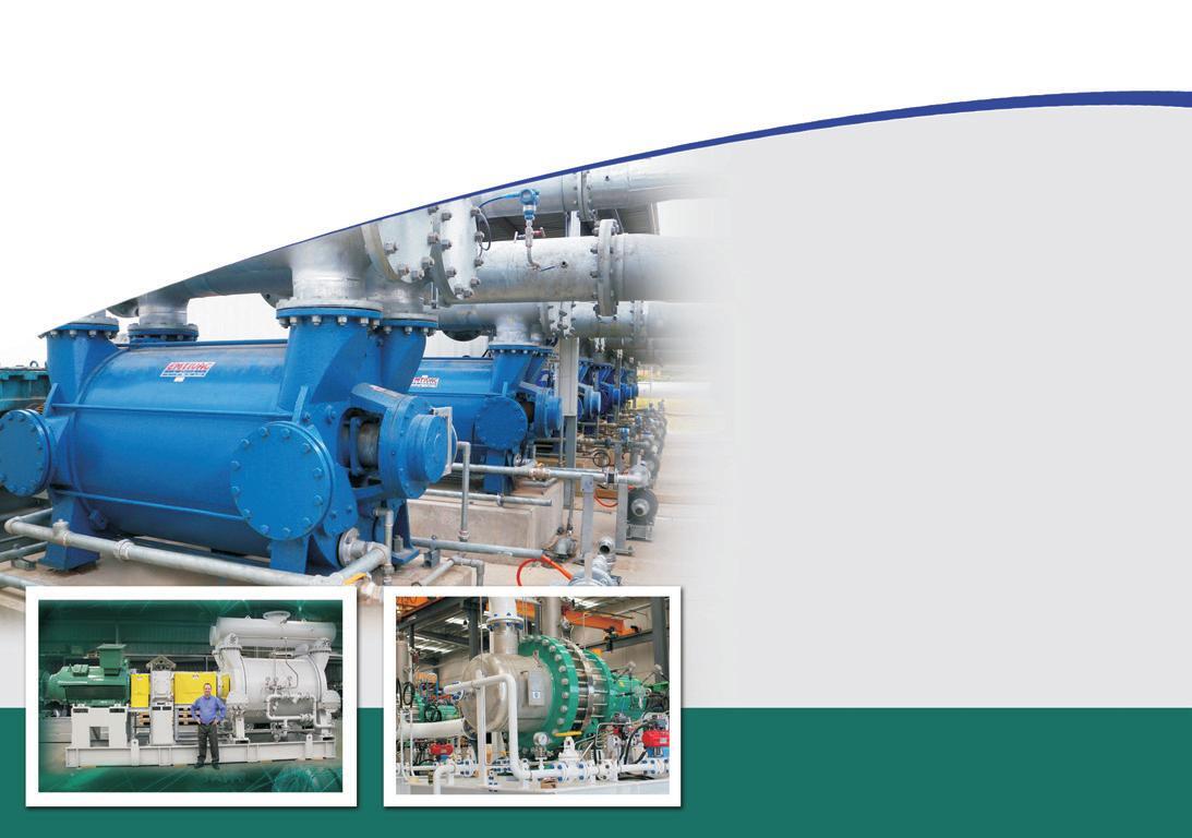
www.pumpindustry.com.au pump industry | Summer 2016 | Issue 14 53 VALVES SUCTION TANK LOAD HEAT EXCHANGER CV1 CV2 OVERFLOW HEADER TANK Normal Flow when pump is working Normal Flow when pump fails SUCTION TANK DISCHARGE TANK Foot Valve Discahrge Check Valve Gas Compressor Crackering Pressure P1 Nitrogen Pure Gas Crackering Pressure P2 Vent For Pressure Relief P2 > P1 Steam Drum Vacuum Breaker Check Valve used as vacuum breaker Drain Level Gauge Steam Stop Valve
7.
remains closed. In case a vacuum is developed in the steam drum, the drum pressure falls below atmospheric and permits the entry of air, thereby breaking the vacuum and preventing the vessel from buckling collapse.
Foot valve
A foot valve in a lift pump is nothing but a check valve placed at pump suction which maintains the pump prime. The check valve on the discharge side ensures that the pump will retain its prime even if the foot valve malfunctions due to clogging etc. Refer to Figure 7.
Mixing streams
Check valves can also be used to maintain the purity of individual streams before they mix. Refer Figure 8.
Combustion systems
Check valves to a certain extent can also mitigate the deflagration risk in pre-mix combustion systems. In case the premix ignites in the mixing pipe the pressure rise accompanied by flame propagation will slam the check valve and may reduce the risk of the flame propagation upstream of check valves. However this is not 100 per cent
fail safe and other means may be required to mitigate this risk. Refer to Figure 9.
Water hammer mitigation
In pumping systems the check valve can also help to mitigate the water hammer. For example if the pump fails, there will be reverse flow from the discharge tank to suction tank. The magnitude of this reverse flow determines the water hammer i.e. the lower the reverse velocity, the lower the pressure rise due to water hammer. The reverse velocity of a check valve is a function of valve inertia and the valve spring constant.
Conclusion
A word of caution to all readers that each application presented above must be properly analysed and undergo a HAZOP (Hazards and Operability) review before it is incorporated in final design. For any questions or clarifications the author can be contacted at neel.kaila@gmail.com.

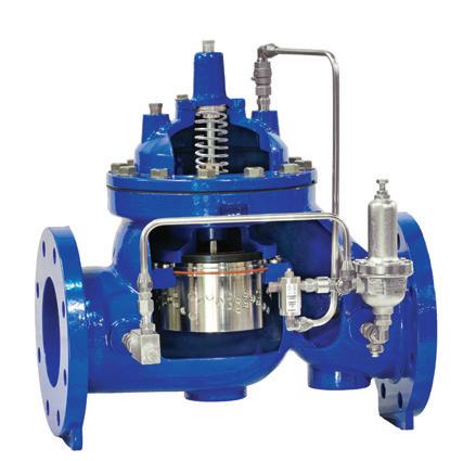
54 pump industry | Summer 2016 | Issue 14 www.pumpindustry.com.au VALVES
Combustion Chamber Gas AIR MIXING PIPE premix VENTURI DON’T SETTLE FOR LESS. singervalve.com
in Queensland, New South Wales, Western Australia, Northern Territory, South Australia, Tasmania, Victoria and ACT FLUID A FLUID B Mixture of Fluid A+B
Represented
Figure 8. Check Valve in MIXING STREAMS.
Figure 9. Check Valves in Premix Combustion Systems.

MANUFACTURING
Find more information online www.pumpindustry.com.au/directory 2016 pumpindustry
WASTEWATER CAPABILITY GUIDE
MINING OIL & HVAC GAS
A beginner’s guide to the right actuator
A valve, in its most basic form, consists of a body and an internal moving component (closure element), which shuts off or restricts flow through the valve. To automate that valve, an actuator is added. The best way to understand valve actuation, however, is to begin by exploring the valves they will drive.
There are many types of valves in the industrial world, which are categorised by type, industry, size, pressure class or one of many other considerations. Which actuator is needed for automation, however, really depends on four basic parameters: motion, force, speed and frequency of operation.
Motion
Classifying valves by the first parameter, motion, means looking at some distinct differences in valve design.
Linear valves
Valves with a closure element that requires linear movement can use a fluid power linear cylinder or a diaphragm coupled to a smooth stem. Alternatively, a multi-turn actuator with an electric or fluid power motor could be used to drive a threaded stem.
Valves with a linear motion on the closure element need a rotary-tolinear conversion mechanism to allow them to be automated by multi-turn actuators. This conversion mechanism is described using one of these three categories of valve stem designation: 1) rising non-rotating stem, 2) rotating non-rising stem, or 3) rising rotating stem.
The rising non-rotating stem valve (Figure 1) is typically a gate valve that has a fixed threaded stem. A matching
threaded nut in the actuator (the stem nut), when rotated, will move the stem up or down. The stem is connected to the disc or plug (closure element) in the valve and the actuator can open or close the valve by rotating the stem nut in a clockwise or counterclockwise direction. Because the stem nut is located in the actuator assembly, the thrust of the valve is also contained in the actuator, usually in the base of the unit.
The rotating non-rising stem valve (Figure 2) works on a similar principle to the rising non-rotating stem valve, but has the stem nut located in the closure element of the valve. This is more complex because the valve design has to allow for the length of the threaded stem to fit inside the closure element as it travels to the open position. The valve thrust is contained in a thrust bearing in the valve top works.
The rising rotating stem (Figure 3) is a hybrid of the previous designs. The stem nut is located in the top of the valve; so, as the stem is rotated, it raises or lowers the closure element. The actuator is coupled to the valve stem with a sliding spline or ‘butterfly’ nut arrangement. Typically the thrust of the valve is contained by the top works of the valve.
Although the closure element moves in a linear fashion, the actuator output is rotary. The movement is converted from a rotary motion to a linear motion by the stem nut.
For valves with no linear-to-rotary conversion mechanism, a linear output actuator is needed to achieve the required motion. The most common of this type are pneumatic linear actuators used to operate process control valves (Figure 4).
Part-turn valves
Most part-turn valves require a quarter turn of the valve stem to move from closed to open and vice-versa. This type of valve, having a standard movement of 90 degrees, allows use of an actuator with a known travel distance. The closure element on the quarter-turn valve could be a disc (butterfly valve), a sphere (ball valve), the frustum of a cone (tapered plug), or a variation or combination of these types (Figures 5 and 6).
Force
The force required to move the valve through its range of motion is critical in selecting an actuator. In the case of sliding stem valves (Figure 7), this force would be a linear push or pull. For multiturn or part-turn valves, a rotary force or torque is required.
The torque (Figure 8) required to operate a valve usually varies with the size of the valve, the valve design and the differential pressure across the valve. Typically, it is this differential pressure in the closed position that
56 pump industry | Summer 2016 | Issue 14 www.pumpindustry.com.au
VALVES
KEY VALVE COMPONENTS
STEM NUT
STEM NUT
THRUST BASE
TOP WORKS
VALVE STEM
ROTATING NON RISING STEM ON GATE VALVE
DRIVE BUSH AND STEM
ACTUATOR DRIVE BUSH
TOP WORKS
THRUST BEARING
THREADED VALVE STEM
STEM NUT
HOLLOW CLOSURE ELEMENT (WEDGE) ACCOMODATES STEM AS VALVE OPENS
SEAT
CLOSURE ELEMENT (WEDGE)
PLUG VALVE WITH RISING ROTATING STEM
ACTUATOR DRIVE BUSH
BUTTERFLY NUT
FIXED VALVE
STEM NUT
THREAD ON STEM
CLOSURE ELEMENT (PLUG)
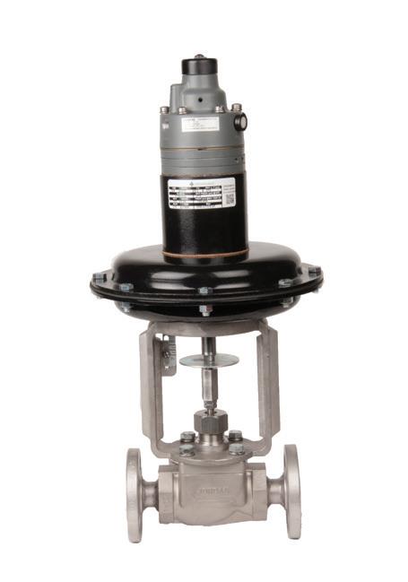
www.pumpindustry.com.au pump industry | Summer 2016 | Issue 14 57 VALVES
STEM
Figure 1. Rising non-rotating stem valve, gate valve.
Figure 3. Rising rotating stem, globe valve.
Figure 4. Linear output, spring diaphragm pneumatic actuator on a sliding stem valve. Image courtesy of Richards Industries.
Figure 2. Rotating non-rising stem, gate valve.
STEM

PLUG VALVE WITH SLIDING STEM
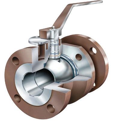
STEM
THREAD TO ATTACH COUPLING
TOP WORKS FLANGE FOR ACTUATOR MOUNTING CLOSURE ELEMENT (PLUG)
Force "F"
Perpendicular distance to line of Force "D"
Torque "T" is the force acting on a moment arm "F" multiplied by the perpendicular distance from the line of force to the pivot point of the moment arm "D" T = F x D
58 pump industry | Summer 2016 | Issue 14 www.pumpindustry.com.au VALVES
Figure 5. Resilient seated butterfly valve. Image courtesy of CIRCOR Energy.
Figure 7. Sliding stem valve.
Figure 8. Rotary force measurement, torque.
Figure 6. Ball valve. Image courtesy of CIRCOR Energy.
Pivot point
creates the greatest force requirement of the valve, which is the force required to open the valve.
The larger the valve closure element, the larger the force on the seats. For some valves, such as gate and globe valves, this force can be calculated and a reasonable estimate of the valve force demand can be made for sizing the actuator.
Other considerations are stem packing friction, the media temperature and the mechanical characteristics of the valve and valve stem.
For quarter-turn valves, however, it is not possible to independently calculate the torque demand of the valve with accuracy. This has to be done by physical measurement of each valve size under the various differential pressure conditions.
Several types and designs of actuator are needed to cover the full range of output force required for covering the spectrum of valve sizes and pressure classes. The greater the valve torque demand, the larger the actuator and the more costly.
Speed
The speed of operation required by a valve application defines what power is needed from the actuator.
Power is defined as work done during a specific time frame. The work done by an actuator is the force demanded by the valve multiplied by the distance over which that force has to be applied (the valve travel). If this work has to be done over one minute, for example, then the power needed would be twice as much as that needed to operate the same valve over two minutes.
For electric actuators, this is a critical parameter because it dictates the motor power. For fluid power actuators, this parameter impacts the size of the
Frequency of operation for automated valves
Continuosly Moving
60 starts per hour Stationary Modulating Duty Regulating
supply and exhaust lines as well as the direction control valve sizing. In both cases, cost is significantly impacted, as is the physical size of the actuator.
Frequency of movement
The preceding valve demand criteria dictates the needed output motion, force output and power of the actuator. The required frequency of operation has a direct impact on the durability of the mechanical drive and robustness of the controller (Figure 9).
Isolating or regulating duty valves and actuators usually only need to operate infrequently. As a result, little wear on mechanical components and controls occurs.
Modulating process valves, however, may operate constantly. This requires a degree of resistance to wear on the valve and actuator assembly. For this reason, it’s important that modulating
4000 starts per hour
2000 starts per hour
1200 starts per hour
600 starts per hour
requirements are factored into the actuator selection. Not only is greater mechanical wear on the drive train possible, but also the controls must be capable of constant change without overheating or failing.
Many subjective opinions have been made on the definition of modulating and regulating duty. However, the industry has adopted milestones of 60 and 1,200 starts per hour for actuator capability. Figure 9 attaches some general nomenclature to those start frequencies.
This column is only a brief description of the key parameters of a valve that must be considered when choosing an actuator. In reality, there are many other options that need to be defined when selecting the appropriate actuator for a valve and its application. These topics are covered in more detail in the book Valve actuators (see below).
Chris Warnett is currently the principal of CPLloyd Consulting (www.cplloydconsulting.com), which provides marketing and applications expertise for the valve automation industry and its customers. He has over 37 years of engineering, sales and marketing experience in valve automation. This column is excerpted from Chris’ book Valve actuators: a comprehensive introduction to the design, selection, sizing and application of valve and damper actuators. For information on purchasing the book, visit www.cplloydconsulting.com or contact Chris at chris@cplloydconsulting.com. This article originally appeared in VALVE Magazine. For the latest valve news head to www.VALVEmagazine.com.
www.pumpindustry.com.au pump industry | Summer 2016 | Issue 14 59 VALVES
Figure 9. Frequency of operation chart.
Duty (on/off)
Duty Isolating
Tips and tricks for maintaining your AODD pump
by David Rozee, Managing Director, TriArk Pumps
Air Operated Double Diaphragm (AODD) pumps have a range of applications across various industries. Here, David Rozee shares the tips and tricks he’s picked up when it comes to maintaining AODD pumps.
AODD pumps are the real workhorses of the industrial pump world and are used in a wide range of industries. These include chemicals, food processing, paints, electronics, road construction, maintenance for industrial processes, electricity production facilities, food processing, wastewater and sludge processing, and mining. They are self-priming, will run dry without doing any damage and use no electricity. Powered completely from compressed air, they are used in applications where electricity is not available or must not be used, such as hazardous or explosive situations or at remote sites.
AODD pumps are particularly versatile in being capable of pumping fluids from fluidised dry powder to shear-sensitive liquids, viscous liquids and abrasive slurries. AODD pumps contain fewer moving parts than many other types of pumps and therefore require less maintenance, yet provide easy access to those parts that may need servicing.
Basic pump components
AODD pumps benefit from their simplicity of operation. Figure 1 shows a schematic diagram of an AODD pump, where A & B are the diaphragms, 1-4
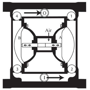
the ball valves and I and O the inlet and outlet ports respectively. The air valve is usually a shuttle valve to route the compressed air alternatively to each diaphragm. The movement of diaphragm A towards the middle of the pump generates a partial vacuum in the chamber. This makes ball valve 1 close, while ball valve 2 opens as air pressure moves liquid from the inlet into the chamber. At the same time, diaphragm B compresses the volume in its chamber, which closes valve 3 and forces fluid past valve 4 and out through the outlet port. When the air valve drives back the movement of the diaphragms, fluid is
pumped through the left hand side of the pump.
Since the diaphragms are fixed to the walls of the pumping chamber, there are no sliding seals in the pump. There are no shaft seals or packing boxes involved. There is a choice of materials for the pump body, diaphragms and ball valves, depending on the fluid to be pumped. Diaphragms and balls are generally elastomer-based or manufactured from thermoplastic materials such as modified PTFE, where maximum chemical resistance is required. Discharge flow rates are adjusted by controlling the air inlet or the discharge flow, so no complicated control systems are required.
Preventative maintenance
AODD pumps are very reliable since they have very few moving parts and components that can wear. They compare very favourably with pumps that have close-fitting sliding or rotating mechanisms, where the passage of abrasive slurries, for example, can cause excessive wear to the moving parts of the pump. This can lead to significant down-time and repair costs. These problems do not arise with AODD pumps since large internal volumes and flow through prevent clogging, with
60 pump industry | Summer 2016 | Issue 14 www.pumpindustry.com.au
REPAIR & MAINTENANCE
Figure 1. AODD pump schematic.
the size of solid particles that can be pumped related to the pump size.
Key factors to consider for preventative maintenance are:
• Diaphragm lifetime
• Compressed air quality
• Flushing of pumps after use.
The diaphragm is a dynamic seal that converts the pneumatic pressure on one side to a fluid pressure on the other (the material to be pumped). Although the differential air pressure across the diaphragm and corresponding internal stresses are lower in comparison with similar stresses in mechanically driven diaphragm pumps that use the diaphragm to generate pressure, the AODD pump diaphragms must flex through millions of cycles to do their work. All diaphragm types will have a finite flex life and the use of a pump stroke counter allows the flex life to be monitored as a part of preventative maintenance good practice. Elastomer diaphragms are typically guaranteed for a flex life of approximately 20 million cycles and PTFE-based diaphragms for around 12 million cycles, but some PTFE diaphragms have been known to last 30 million cycles. Although the pumps can run dry with no damage, diaphragm flex life can be reduced if the pump runs dry for extended periods of time.
Careful consideration should be given to the compressed air supply used. Air is drawn into the compressor from the atmosphere and will contain some moisture. This air expands rapidly inside the pump with the result that the water can freeze. The ice formed on the moving parts of the air valve can cause them to stick, causing the pump to stall. Although air valves are designed to minimise this possibility, it is good practice to make sure that the air is dried before it enters the compressor. In addition, engineers frequently lubricate a compressed air line. This practice should be avoided due to the potential to contaminate the pumped fluid. There is an additional environmental benefit to using oil-free compressed air since no oil mist is vented into the atmosphere
as well as the fact that there are also no costs associated with oil consumption or lubrication.
Since AODD pumps can be used for pumping such a wide range of fluids, consideration should be given to flushing the pump through after use, especially for fluids such as concrete, or glue, which will solidify in the pump if not removed after pumping is complete. Once a substance has solidified in the
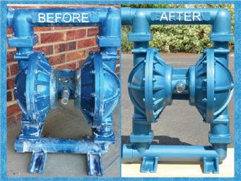

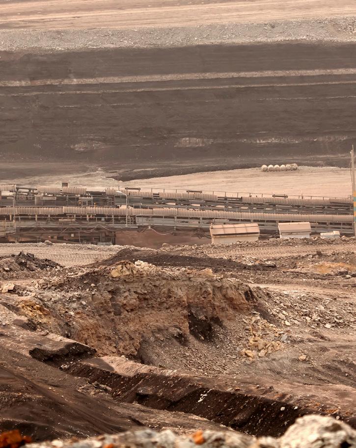
DEWATERING PUMPING?

www.pumpindustry.com.au pump industry | Summer 2016 | Issue 14 61 REPAIR & MAINTENANCE
pioneerpump.com We offer more efficient, more economical pumps that outperform equivalent sized packages. Our extrememly competitive pricing doesn‘t compromise quality, and gives you more bang for your buck. All of our packages are built from the ground up in Australia, and meant to withstand the harshest conditions.
Look at Pioneer Pump for the best solutions. • 50 cfm vacuum priming pump/system to prime faster. • Lift higher with better NPSH characteristics. • All Ductile Iron Casing and hardened SS impeller for longer product life. • Patented Pioneer Pump Spring loaded Posi Lock Air Value design in priming chamber allows no blow-by, reduced impact on the environment. • Modular design of pumps, skids and fuel cell bases for faster delivery time. Contact Sales: 03 9988 1650 Email: ppausales@pioneerpump.com 67 Proximity Drive, Sunshine West, Vic 3020 pioneerpump.com.au Figure 2. Blagdon B50 AODD pump before and after refurbishment by Tri-Ark Pumps Ltd.
Maintenance and repair strategies
Since AODD pumps are used in such a wide range of applications and industries, individual users will have their own approach to maintenance and repair strategies. Uses can vary from the occasional emptying of a container using the pump as a scavenger, to 24/7 use on a critical production line. Although AODD pumps are easily dismantled for maintenance or diaphragm replacement, not all users will want to carry out their own maintenance or repair - they may prefer to return the pump to the supplier for refurbishment. Most AODD pumps come with a manufacturer’s five year warranty (excluding consumable items) but often a pump returned under warranty will undergo a lengthy investigation by the manufacturer to
decide the cause of the fault, and that could be very disruptive to a user. Some independent suppliers will offer a 5 year no quibble guarantee which avoids this lengthy process.
For pumps being used in critical 24/7 applications, having a spare pump that can be swapped in the event of a pump failure is essential. This may literally be a spare, or one being used in a different application that can be used at short notice. The most comprehensive approach would be a three-pump strategy – one in use, and two spares. In the event of a failure, the damaged pump is replaced by a spare and returned for repair, still leaving a spare on site while the repair is carried out.
For companies who want to carry out their own repairs, an ‘airside’ repair kit can be provided which contains components such as ball valves,

diaphragm valve seats etc. that are in contact with the pumped fluid, and a ‘dry side’ kit which contains items such as a pump shaft, o-rings, gaskets etc. For many years now, companies have sought to lower their overheads by holding less stock, so many end users may be reluctant to hold spares for their pumps.
Finally, the cost of repairs and refurbishment should be considered. In today’s ‘consumable society’, it is often cheaper to simply buy new rather than pay for a repair. In the world of AODD pumps, the rule of thumb is that pumps less than a 1/2” are generally not worth repairing.

62 pump industry | Summer 2016 | Issue 14 www.pumpindustry.com.au REPAIR & MAINTENANCE
Visit www.triark.com. INNOVATION & EXPERIENCE IN PUMPED FLUID SYSTEMS New and improved facility with 10 tonne crane capacity & pump test facility to 300kw. 115 Munibung Rd, Cardiff NSW 2285 Ph: (02) 4922 9020 Fax: (02) 4954 20320 pumps@bcip.com.au www.bcip.com.au System Design Water Recycling Systems Filtration Water Treatment Systems Irrigation Design & Installation STABLE FOUNDATION EXTENDED CAPABILITIES Condition Monitoring Asset Management Risk Assessment Audits Pipe System Flow Modelling Field & Workshop Repairs
David Rozee is the Managing Director of TriArk Pumps.
Are you following maintenance best practices?
by Heinz P. Bloch, PE, Process Machinery Consulting

Maintenance best practices for pumps in industrial and municipal services deserve more of our attention than we seem to routinely give them. Well-explained details for pump maintenance best practices can be found in a wide variety of published literature; there’s really no excuse not to have your maintenance regime up to scratch.
Generally speaking, relevant details are in the public domain, in plain view of those truly interested in learning, and we do our part to encourage reliability professionals and managers to embrace maintenance best practices for pumps. Some need to make changes if the right priority is not presently given to the implementation of true maintenance best practices. Elevating the priority ranking of doing repairs properly often requires a shift in the mindset of managers and senior professionals. But while managers and maintenance personnel tend to desire quick results
– and because human nature is what it is – changes in mindsets are needed. Even a subconscious awareness of having to make changes becomes an obstacle to the implementation of best practices. Bear with me and I will explain.
Precursor activities
Maintenance best practices are achieved only after having done due diligence. In other words, precursor activities have to be carried out. By way of analogy: the reliability of a passenger car is dependent upon (a) its design, (b) the quality and diligence of follow-up maintenance, and (c) the competence
www.pumpindustry.com.au pump industry | Summer 2016 | Issue 14 63
REPAIR & MAINTENANCE
of the car’s driver-operator. It’s no different in a pump user facility: each of these entities – design, maintenance, operation – must do their respective jobs correctly. Unless all three are done well, there will be no reliability. While there will be much talk about best practices, little (if anything) is often done to impart lasting value.
Project engineering
Again reverting to an automobile analogy, planning to market a new automobile model involves up-front design. Design details always create maintenance consequences. It is no different with the assets which end up in a pump user’s facility. All the maintenance efforts in the world cannot turn a fundamentally bad or maintenance-intensive design into a technically superior asset.
The fact is: you cannot make a silk purse out of a sow’s ear. A facility needs a sensible budget, not a bare-bones budget. Good projects originate with cost estimating manuals that reflect reliable equipment. A project must use experience-based specifications to describe and properly estimate the cost of reliable equipment. Reliable assets must be purchased and installed. Before the actual commissioning, soundly executed projects move into a training phase. People must learn (i.e., be trained) in how to properly operate and maintain this equipment.
Don’t blame others!
A logical realisation is to rule-out finger-pointing and fault-finding between a maintenance department and an operating department. The smartest organisations are conveying to the maintenance department head that he or she will be asked, at random intervals, to trade places with the operations department head. The operations department head will then become the maintenance department head. That simply means that the two department heads will positively learn to communicate and cooperate; they will adopt a statute whereby they show consideration for each other’s issues and concerns on a daily basis. If they don’t learn to communicate and cooperate, each will have terminated their own careers.
Input from SMEs
Best maintenance practices are put in writing; and they require input from subject matter experts (SMEs). SMEs are not born; they are groomed and nurtured. These experts may report at different levels in an organisation, but will be given access to a sponsor, someone very near the top. SMEs are people with abilities and know-how which would be perilous for project people to ignore. SMEs are given a role statement which delineates their role and assigns to them both accountability and empowerment. Their role quite obviously includes project involvement up-front, never after decisions are already made by managers whose concerns are inevitably focused on the present and for whom the future is too far out to be of concern. Regrettably, in today’s environment reward and progression are often based entirely on cost and schedule instead of long-term lowest cost of ownership.
Owners of decisions
In our context, ‘owner’ simply means that best practices companies designate an ‘owner of final decisions’. That owner of decisions has to live with his rulings, first as the project executive, then as the plant manager. He or she instructs the next layer of managers to use predictive maintenance routines which are tracked so as to identify the optimum maintenance or scheduled shutdown intervals. It’s in this particular layer of management where the trading of places between an operating department head and a maintenance department head takes place. It is this layer of management which sees to it that written instructions are followed, be they maintenance or operationsrelated. The managers in this layer are held accountable and, in turn, will hold accountable the supervisory levels reporting to them.
Deming was right
Following the above roadmap for several decades will inculcate in an organisation what an exceedingly competent observer of the world scene, W. Edwards Deming, taught with absolute clarity in the mid-1940s. In his ‘14 points of total quality management’, Deming described a set of management
Figure 1.
A bi-directional tapered pumping ring is typical of the many upgrade components available for mechanical seals in process pumps (Source: AESSEAL, Rotherham, UK).
practices which bring about quality and productivity. Wildly optimistic maintenance practitioners (and their disciples) sometimes push aside Deming and replace his fundamental principles with a new flavour of the year. Shortly after World War II, Deming tried to provide highly relevant in-depth consulting services to US automobile makers. When the US auto industry ignored his work, Deming went to Japan and assisted Japan’s auto industry to regain and expand both quality and market share. We now know that Deming was right over 75 years ago; we also know that his principles are as true today as ever.
Rediscovering these practices and following Deming’s guidance towards maintenance best practices makes a lot of sense. We can certainly apply his thinking to the process pumps we design, manufacture, install, repair, maintain, and operate:
1. Create constancy of purpose for improvement of product and service.
A reliability engineering group must view every maintenance event as an opportunity to upgrade. The investigation of the feasibility of upgrading (see Figure 1) should have been done beforehand; it should be a pro-active endeavor.
2. Adopt a new philosophy which makes mistakes and negativism unacceptable.
Accountability is the key here. If you’ve taken your car to the dealer on three consecutive Mondays to have a leaking water pump repaired and find the job to be unsatisfactory every time, you might ask some serious questions. Why not ask
64 pump industry | Summer 2016 | Issue 14 www.pumpindustry.com.au REPAIR & MAINTENANCE
questions at your plant when a critical process pump repair isn’t done right three times in a row? Why the double standard as we shift from our automobile to the plant’s process pumps?
3. Stop being dependent on mass inspection.
While this is not usually a concern for a pump user’s facility, invoke the corollary. Ask the responsible worker or maintenance technician to certify that his work meets the quality and accuracy requirements stipulated in your facility’s work procedures and checklists.
4. End the practice of awarding business on price alone.
You’ve probably never bought the least expensive pair of shoes, so don’t buy the cheapest pump, or the cheapest replacement parts for the pump. Understand and redefine the function of your purchasing department. Let them negotiate price and delivery of the mechanical seals and rolling element bearings specified and selected by a competent reliability engineering group, but don’t let the seal vendor lobby your buyers. Pay particular attention to the meaning of ‘specify’ and work up detailed specifications for important parts.
5. Improve constantly and forever the system of production and service. Understand that in a process plant, improvement will come from the proper daily interaction of operating, mechanical/maintenance and reliability/technical workforces. Be sure not to let the reliability/ technical function become a service organisation. They are the support arm which needs to push your company to the top. Don’t let them get inbred by depriving them of access to the outside world.
6. Institute training.
It has been our experience that very few managers know just exactly what type of training is required by their mechanical/maintenance or reliability/technical workforces. Say, for example, the shop is primarily involved in repairing repeat pump failure events. The mechanic or machinist dismantles a pump, finds a defective bearing and replaces it. For decades that’s been your repair approach, but not so at the bestof-class competition. Your best-ofclass competition probably taught
their personnel that bearings fail for a reason, and unless you uncover the reason, you are just setting yourself up for many more repeat failures.
7. Institute leadership. What an elusive concept it is! Perhaps we could look at a small slice of it, the one that deals simply with guidance and direction. A leader recognises that for reliability professionals to be productive, they must be resourceful. The leader must be in a position to outline the approach to be followed by the reliability professionals in, say, achieving extended pump run lengths. The true leader would steer professionals to publications and mentors, would recommend the development of single-page specifications for acceptable bearing types and configurations, and would see to it that inquiries to mechanical seal manufacturers would elicit responses in sufficient detail to acquire the statistical basis for justifying the procurement of better products.
8. Drive out fear. In my younger years we used to have an unwritten contract which implied that employee loyalty will be rewarded by job security. This contract no longer exists today. But you can initiate guidance and action steps that show personal ethics and evenhandedness which are valued
and respected by your workforce. Their performance will be motivated by your example, by your work habits and character traits. Fear will no longer be a performance motivator.
9. Break down barriers between staff areas.
You should never tolerate the kind of ill-perceived competition among staff groups that invariably cause them to withhold pertinent information from each other, or makes one group shine at the expense of their peers.
10. Eliminate slogans and exhortations for the workforce.
Just because a catchy safety slogan at the plant entrance serves as a fitting reminder to work safely does not mean that hot-air exhortations will strike a responsive chord. We all subscribe to the belief that actions speak louder than words.
11. Eliminate numerical quotas. Think how well your automobile would be repaired if the mechanic had a quota of eight automobile repairs per day. If your reliability professionals work a 40-hour week and you expect them to solve 20 problems per week, don’t be surprised if they do a rather superficial job, at best. If a problem is worth solving, allocate the time needed to do the work. One powerful reason why some process
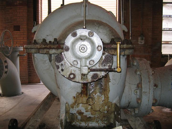
www.pumpindustry.com.au pump industry | Summer 2016 | Issue 14 65 REPAIR & MAINTENANCE
Figure 2. Process pump in distress. (Source: author).
plants are only marginally profitable is because they claim to have neither the time nor the money to do the job right the first time, but somehow end up doing it over a second and third time. That’s not how the best-of-class competition operates!
12. Remove barriers to pride of workmanship.
Give your reliability person credit for keeping his or her work environment clean. Don’t convey the message that the job must be done so quickly that there is no time to make it look good (see Figure 2), no time to accurately monitor bearing temperatures in the induction heater, no time to calibrate the torque wrench. If reliability could be achieved without pride of workmanship, we would be happy to take delivery of a new car with ill-fitting doors and streaky paint. And the surgical scar on a hospital patient might as well look like the zipper on an old mailbag if nobody cares!
13. Institute a vigorous program of training and education.
I’ve asked myself why W. E. Deming seems to repeat himself in listing
TRAINING under numbers 6 and also number 13. No doubt he wanted to underscore the staggering importance of training to the achievement of consistently high quality, productivity and profitability. We can be equally certain that Deming understood that engineers leaving colleges and universities require copious amounts of additional training in order to be productive and proficient contributors. This training may come from such sources as trade journals, vendor seminars, or even the assignment of presentations to Management or to certain Operations Groups. Two of the most costly Management misconceptions are that maintenance can always be deferred and that training the workforce is no more important than the (occasionally misguided) training executives are often receiving from industrial psychologists, wild water rafters and golf pros.
14. Go beyond a plan, and take action to achieve this transformation. Taking action means exercising leadership. Leadership must come from a perceptive, knowledgeable
individual. Risks must be assessed, roadblocks and impediments must be removed. Leadership is needed because new directives have to be communicated to others. Their cooperation has to be sought and “empowerment” redefined in some instances. Deming used the term “transformation” because he no doubt realised that that’s what it may take to escape from the constraints the traditional mindset is imposing on the pump maintenance worker.
Finally, the most productive and highly profitable pump users are ones viewing every maintenance intervention as an opportunity to upgrade. At these best-of-class companies a maintenance or reliability professional is ready and able to answer two questions without delay and hesitation: (1) is upgrading possible, and (2) if upgrading is possible, will it be cost-justified in the particular case at issue?
Designating, grooming and rewarding such an individual will be of great value to the enterprise. It will promote good reading habits and is sure to drive down pump failure frequencies.


66 pump industry | Summer 2016 | Issue 14 www.pumpindustry.com.au REPAIR & MAINTENANCE
Phone (03) 9873 8744, or email sales@hebco.com.au For sales and support, call H.E Brehaut Pty Ltd. Australia's Amarillo experts since 1982.
Getting to know your pump system: specific speed and system head
The PIA’s Australian Pump Technical Handbook is a cornerstone text for the Australian pump industry. In this ongoing series, we feature abridged chapters from the classic book to showcase the various areas covered and to reacquaint readers with the technical aspects of pumps. In this issue, we explore the concepts of specific speed and system head.
Specific speed
Specific speed is a criterion used to describe the discharge characteristics of a pump. Specific speed is the speed at which an ideal pump, geometrically similar to the actual pump, will raise a unit of volume in a unit of time through a unit of head. The specific speed of a pump is calculated from pump speed, total head and flowrate data at BEP.
The normal range of specific speed is from 500 to 12,500. Generally, pumps with a high flowrate and low head have high specific speed values, while pumps with high head at a low flowrate have lower specific speeds.
The specific speed relates to the geometry of the pump rotor and is independent of pump size.
Specific speed can be used to categorise centrifugal pumps, allowing the pump user to determine the type of pump required for a given application. Choosing a more efficient pump for an application can significantly reduce costs.
Specific speed and efficiency
The maximum efficiency a pump can attain is heavily reliant on specific speed. In general, efficiency increases as the specific speed rises.
Specific speed not only relates to impeller geometry, but also the trend of the characteristic curves for total dynamic head, power consumption and efficiency.
At low specific speed, power consumption is at a minimum of zero flowrate, and rises as flowrate does. This is an overloading characteristic and the motor must be sized to meet the conditions that may occur during operation.
At medium specific speed, this is a non-overloading characteristic and the pump can operate safely across the
entire flow range with a motor sized to meet the peak requirements.
High specific speed pumps have a falling power characteristic with maximum power occurring at minimum flow. This means they should not be used in zero flow conditions. Discharge throttle valves or bypass systems should be avoided and variable speed drives should be considered for such systems.
System head
In a general sense, ‘head’ is a measure of the pressure imparted to a fluid in a pump system, referring to the height (in metres) of a fluid column that can be supported by the pump’s output. Mathematically, ‘head’ is the energy per unit weight of the pumped liquid in a system. Knowing the total head of a system is necessary in order to calculate values such as the specific speed of a pump system and determine if a pump is operating efficiently.
However, head can be lost in numerous ways throughout a system and a number of different factors of the system in question will affect the value of the system’s head.
Friction losses in pipes and fittings
As a liquid flows through a system the resistance it encounters results in a loss of head. This loss is commonly known as ‘friction loss’ and is measured in metres of liquid or head.
The head loss in a given system is a function of the roughness of the pipe’s interior surface, the length of pipe through which the fluid must travel, the fluid velocity and fluid viscosity.
Additional losses are generated by obstructions to the flow path caused by valves, fittings and other system components, bends and changes in direction, and changes in the cross section or shape of the flow path. Head can also be lost at the inlet and exit of a piping system.
The friction losses throughout a system can be calculated by accounting for these factors using equations, tables and formula included in the Australian Pump Technical Handbook and Pipe Friction Handbook.
The uses of head
For centrifugal and rotodynamic pumps ‘head’ is the parameter directly relating to the energy available to overcome pump inlet losses. This relationship is more complicated for other types of pump, such as reciprocating positive displacement pumps, where the flow varies during the pumping cycle. For these types of pumps valve lift pressures and fluid acceleration and deceleration may affect the system head. Therefore the guidance of the pump manufacturer may be necessary to ensure that all necessary factors have been considered.
Further information and detailed diagrams, equations and schematics can be found in the Australian Pump Technical Handbook, available from the PIA website (pumps.asn.au/publications).
In the next edition of Pump Industry we will look at how to select the right centrifugal pump for a particular application.
www.pumpindustry.com.au pump industry | Summer 2016 | Issue 14 67
TECHNICAL
This is an edited extract from the Australian Pump Technical Handbook which can be ordered online at pumps.asn.au/publications.
Bob Pullen
With over 50 years experience in the pump industry, Bob Pullen has had a long and exciting career. From establishing Pullen Fluid Dynamics, acquiring Jay and Short Pumps and publishing the first ever Australian Pump Journal, his passion for the industry is evident. Bob shares his thoughts about his career, the industry today and why he’s just not ready for retirement.
Starting out
In 1960, after completing the first year of a Technical College course in mechanical and electrical engineering, I applied for the position of cadet engineer with McPhersons Ltd at Ajax Pumps. I was anxious to join the workforce during the day and complete my studies at night, because I wanted to combine Technical Studies with daily hands-on, practical experience.
The program offered an interesting mix of workshop and engineering office training, and as a cadet, the industry immediately took my interest. It was (and still is) something that consumes and motivates me. After Ajax Pump Works factory training, I was transferred into sales, and the face-to-face experience is where the learning really began.
Passionate about pumps
What I like about the pump industry is the diversity. As the second most used machine in the world, you will find pumps in mining, food processing, waste disposal, fire protection, flood mitigation, irrigation and many, many more industries. Each application is a little different.
For example, mining demands an understanding of critical carrying velocity and wear resistance while food processing demands an understanding of hygiene and pump design that can be easily cleaned in place. Of course there are many more examples but the lesson is clear – each industry has its unique requirements and the pump engineer must have a broad knowledge.
A long and varied career
After Ajax Pumps, I joined FN Bethune (Pomona Pumps) as an Industrial Sales Engineer. Not long after I started there, R.J. (Bob) Moore from Kelly and Lewis was appointed the new General Manager.
Although I was probably too young, Mr Moore promoted me to Victorian Sales Manager and gave me a staff of three. Outside of my Victorian state responsibilities, I was sent to Gladstone Alumina Refinery to commission large slurry pumps, to Tasmania to commission mining dredge pumps, as well as many other responsibilities that gave me a look into life outside the office.
With the approval and encouragement of Mr Moore, I branched out into self employment and created Fluid Dynamic Engineering with Frank Muscroft. Together, we manufactured stainless steel milk transfer pumps for Kraft Foods and food handling pumps for Shepparton Preserving Company.
We also made a well-intentioned effort at publishing the very first Australian Pump Journal in July 1968. High on enthusiasm, but short of working capital, it lasted for only a few issues, proving that there is merit in having a business plan before starting a new venture, rather than just having high hopes. However, I’m delighted to see the current Pump Industry magazine succeed in providing a quality informative source of information and training.
After a few years, Frank Muscroft moved on, and Kelly and Lewis acquired Fluid Dynamic Engineering. It was then that I started a new venture, Pullen Fluid Dynamics. At Pullen Fluid Dynamics I continued with food handling and milk transfer pumps, but I also developed a range of corrosion resistant chemical pumps known as the Red Dart and a range of Australian designed and built submersible sewage pumps. Second only I think to Don Forrer.
Simpson Pope provided us with the electrical components while we developed the non-clog pump end, the motor stator body and the cover

components. Marcel Herzig from Sulzer Pumps in Switzerland then joined us as our designer, and from there we were in a serious business supplying pumps to various Water Authorities around Australia, who all had high expectations of design and quality. The growth of Pullen Fluid Dynamics led to my next and most important development, which was my acquisition of the Sydney based Pump Company J.T. Jay in the early 1970s.
J.T. Jay, also known as Jay and Short Pumps, had a proud 100-year history and a top class reputation with the Sydney Water Board and NSW Department of Public Works. Jay and Short not only designed solid case and split case sewage pumps, but they had their own cast iron and bronze foundry.
The Jay acquisition provided the youthful staff at Pullen Fluid Dynamics with their own foundry, as well as a fully equipped machine shop. With a name change to Pullen-Jay Pumps and the introduction of submersible sewage pumps into the solid and split case sewage pump range, it didn’t take long before sales ballooned.
68 pump industry | Summer 2016 | Issue 14 www.pumpindustry.com.au
PUMP PIONEERS
Bob Pullen.
Heading overseas
Some of the products we built at Pullen Fluid Dynamics for Sydney Water were large 450mm vertical split case sewage pumps, so I saw the need for a manufacturing colleague with casting and machining capabilities that were beyond the Pullen Jay team.
After several visits to Malaysia, I negotiated a manufacturing and design agreement with Chung Khong Engineering in Ipoh. Marcel designed the casings and impellers in Australia, and Chung Khong cast and machined the large components in Malaysia. We then assembled and tested the complete pumps back in Australia. Back in 1970 this was probably one of the earliest joint offshore manufacturing agreements entered into by an Australian Company.
Chung Khong also had their own range of Ni-hard metal pumps for the Malaysian tin mining industry, and I was fortunate to learn by watching them work in the mines. While I didn’t know it at the time, my knowledge and respect for the Chinese owners of Chung Khong was to serve me well in my later pump manufacturing pursuits in Mainland China, over twenty years later.
As the ‘new kid on the block’ in the Australian sewage pump market, it didn’t take long for the UK based pump company Allen Gwynnes to show an interest in Pullen Jay Pumps. Allen Gwynnes, Amalgamated Power Engineering, purchased Pullen Jay Pumps in 1975 and I was required to leave the pump industry because I signed a non-compete clause in the agreement.
During this enforced absence I tried a number of different career options: motor vehicle manufacture, cranes, superannuation planning, fibreglass, transmission, and even a brief venture into catering, but none of these satisfied me, so inevitably I came back to pumps.
Drawn back to pumps
It was a breath of fresh air when Colin Montgomery of Duraqual Pumps and Bill Smith of Kelair Pumps gave me the opportunity to rejoin the pump industry.
At Duraqual Pumps, I learned about the different high pressure piston pumps and diaphragm metering pumps. From chemical dosing to water jet cutting of concrete, the Duraqual
experience was a whole new world for me.
At Kelair Pumps, my role as ABS (Germany) Product Manager saw me travel to Sweden, Germany and Ireland, as well as around Australia. We enjoyed great success with the large ABS range of water and sewage pumps offered to government authorities both in Australia and New Zealand. I remain indebted to Bill Smith for this opportunity as it was an exciting time for all of us at Kelair after we successfully launched this large product range.
After Kelair Pumps, I moved on to Nossiter Pumps. Ben Nossiter offered me a consulting role, as he wanted to expand his business into export opportunities. Indirectly, this resulted in me making contact with Lanshen Pumps in Nanjing China, who, ironically, had been manufacturing ABS pumps under licence at the time I was ABS Product Manager.
The pieces of my jigsaw puzzle quickly fitted together, as my early Malaysian Chung Khong Chinese experience allowed me to seamlessly adapt to the mainland Chinese business protocol, which is very different from Australian and European business practices.
My various interlocking relationships from Pullen Jay, Chung Khong, Kelair, ABS Germany and Lanshen opened the door for me to a design and manufacturing agreement with Clearet Environmental Technology in Suzhou China to produce a range of small submersible sewage and drainage pumps. I also assisted in setting up a polyethylene rotomolding factory in a Suzhou factory, which now manufactures its own polyethylene pump stations for the local Chinese market.
The (possible) final chapter of my story is my present endeavour at SPE Polytech, manufacturing polyethylene package pump stations in Australia. I look back on the 55 years since I first joined Ajax Pumps and I am very grateful for the opportunities that the Australian pump industry and some key people have presented to me.
Changes in the industry
I think pump designs are now more efficient, refined and OHS conscious, and electrical controllers are much more
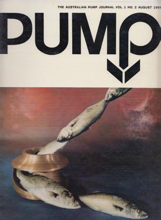


www.pumpindustry.com.au pump industry | Summer 2016 | Issue 14 69 PUMP PIONEERS
sophisticated. We now also have access to a wider database of basic application knowledge through the internet, but sadly there is generally a lack of product knowledge, which is no doubt brought on by lack of training. The problem of lack of training can be directly related to the reduction in Australian manufacturing, as the importation of pumps from Asia has had a major impact, and this is a topic that raises heated debate.
In terms of suppliers I think there are too many importers for our population of 23 million. My personal involvement in offshore manufacturing has given me an inside view from both sides of this issue, but it cannot be denied that it has had an impact on the larger Australian pump manufacturers, resulting in less research, development and staff training.
Career highlights
There are two memorable moments that stand out in my career. The first was the bittersweet creation of The Australian Pump Journal in 1968. This venture had all the exuberance and energy of youth, but without the wisdom and experience that only comes in later years.
The second highlight was the acquisition of Jay and Short Pumps in my early thirties. The feeling of being a part of their long history and past heritage, combined with the energy of my youth was a great experience. J.T. Jay showed me where others in the pump industry had been before us, walking the same road and designing and building similar pumps.
It’s all about the people
Three people stand out as mentors in my career: Bob Moore of FN Bethune (Pomona Pumps), Colin Montgomery of Duraqual Pumps and Bill Smith of Kelair (ABS Pumps).
Bob Moore threw me in the deep end, but stayed around long enough to teach me to swim. He made me a state sales manager at 23 years old and he gave me the experience to supervise site commissioning of large mining slurry pumps all around Australia.
As Colin Montgomery’s General Manager, I learned the art of ultra high pressure pumping along with his wide range of metering pumps. He also gave
me extensive travel opportunities in Australia and Asia.
Lastly, Bill Smith gave me the opportunity to rejoin the Australian pump industry after my enforced non-compete absence, following the sale of Pullen-Jay. As his ABS Product Manager, I visited ABS pump factories in Sweden, Germany and Ireland. We also introduced the Blivet package sewage treatment plant into Australia and Indonesia.
I’ve also worked with many other personalities in the industry. Without a doubt, John Link is one of the most colourful and interesting people in the pump industry. During one of my many visits to my colleagues Chung Khong Engineering in Malaysia, John arrived one day riding a motorcycle through the jungle, with his long grey beard flowing in the wind and multicoloured Malaysian Batik crash helmet on his head. He certainly made my conservative grey business suit, white shirt and blue tie seem drab by comparison. After time at Pullen Jay, Brian pritchard went on to own and operate B-Line Pumps.
Significant industry developments
Without a doubt, the most significant development that I have witnessed is the sad, but inevitable, demise of major Australian pump manufacturers.
From as far back as the 1960s and 1970s, Australia has suffered from a small population base compared to Europe, America and Japan. Australian manufacturers could not enjoy the economies of scale afforded to their overseas competitors. This meant that research and development was difficult to fund against a lower sales volume.
Lowering the rate of import duty was a factor. People have argued that this was a necessary step for the overall Australian economy to produce a level playing field, and that the loss of some Australian pump manufacturers along the way was collateral damage. In later years, the emergence of Asia, with the benefit of low cost labour and rapidly improving technology, finished off the decline.
The news is not all bad though, as innovative, specialised design and manufacturing is the future challenge for the Australian pump industry, and Australians are versatile and flexible
thinkers. During my many visits to China, I have witnessed the ability of the Chinese to experiment and perfect the art of manufacturing, but I have also witnessed their limitation in the flexible use of their individual components to produce an even wider range of pumps. Australians have no such limits in their imagination of multiple practical installation possibilities. So here is an opportunity for Australia to be flexible and innovative.
The greatest challenge facing the pump industry today is to think outside the square. We need to find a better way to do what has already been done and find existing markets that are not well serviced and then fill the void. If the pump is the second most used machine in the world, then the opportunities are widespread- if you can recognise them.
Life today
These days I’m working at SPE Polytech where I manufacture polyethylene underground package pump stations. At 72 years old, I get my fair share of friendly criticism from my retired friends, when I am continually unable to accept their invitations for bowls or golf. However, I am proud to say that SPE Polytech have sold into all Australian states and my products are now used by many prestigious pump companies. They have been exported to New Zealand, New Guinea, Vanuatu, Fiji and the Solomon Islands.
Outside of the industry, my wife Denise and I are about to celebrate our 50th wedding anniversary. In our spare time we enjoy going to restaurants and live theatre, as well as seeing our sons Grant and Craig, their partners Carolyn and Cindy and our four grandchildren Ben, Ally, Josh and Brooke. We are now watching the grandchildren prepare for university which is a real treat. Ben is already in his first year of a Business/ Law Degree and Josh is about to enter Business/Marketing. So who knows, maybe they are two new ‘Pump Men’ in the making.
If I could give any advice to pump industry professionals today, it would be that while training and knowledge are prerequisites, your attitude, commitment, service and ability to go the extra distance are just as important. Never stop learning, and don’t just make the pump industry a job – make it a career.
70 pump industry | Summer 2016 | Issue 14 www.pumpindustry.com.au PUMP PIONEERS
PUMP SCHOOL

Question: Answer:
There are two general types:
Which pump do I choose?
As a pump user you will be confronted with the decision as to whether your application requires a dynamic or positive displacement pump.
1. Rotodynamic (which the main sub-classification is centrifugal)
2. Positive displacement
Rotodynamic
Rotodynamic pumps are rotary machines in which energy is continuously imparted to the pumped liquid by a rotating impeller, propeller or rotor.
Positive displacement
Positive displacement pumps are rotary or reciprocating machines in which energy is periodically added by application
of force to movable boundaries of enclosed fluid containing volumes, resulting in a direct increase in pressure.
In general, the basic conclusion/rule is that:
• Centrifugal pumps are for pumping clean, low viscosity liquids
• Positive displacement pumps are best for slurries and high viscosity liquids.
As with all general rules there are important exceptions – in fact there are times when you can use a centrifugal pump on high viscosity and when you can employ a positive displacement pump for clean, cold, low viscosity liquids. If in doubt, consult your pump supplier.
www.pumpindustry.com.au pump industry | Summer 2016 | Issue 14 71
Article courtesy of Kelair Pumps Australia – When Pump Knowledge Matters. For more information phone 1300 789 466 or visit www.kelairpumps.com.au.
Rotodynamic Centrifugal Radial Flow Mixed Flow Axial Flow Single Suction Double Suction Self-Priming Non Self-Priming Jet (Ejector Boosted) Gas Lift Electromagnetic Special Peripheral Single Suction Single Stage Multistage Single Stage Multistage Open Impeller Closed impeller Single Stage Multistage Open Impeller Semi-Open Impeller Closed impeller Positive Displacement Reciprocating Piston Plunger Diaphragm Mechanical Diaphragm Piston/Plunger Hydraulically Actualed Diaphragm Vane Piston Flexible Member Screw Gear Lobe Circumferential Piston Screw Controlled Volume Single Acting Double Acting Single Rotor Multiple Rotor Rotary Rotodynamic Positive displacement
72 pump industry | Summer 2016 | Issue 14 www.pumpindustry.com.au ADVERTISERS’ INDEX Action Aquatics 44 Allight Sykes ............................................. 27 Angus Flexible Pipelines 13 Applied Pump Engineering 3 ASM Pumps 51 Australian Pump Industries 37 Brown Brothers Australia ...................... 19 Crusader Hose ......................................... 6 Deanquip ................................................... 22 Emtivac Engineering 53 Irrigation Australia 2016 IBC FCR Motion Technology 23 Franklin ........................................................ 11 Goodwin Submersible Pumps Australia.35 Hebco .......................................................... 66 Hydro Australia ......................................... 9 Hydro Innovations 17 Hydroflo Solutions 62 Integra Drive & Automation Services 41 Kelair Pumps Australia 36 Link Pumps ................................................ 24 LK Diesel Service ..................................... 38 Marcor ......................................................... 26 Millennium Coupling Company 50 Pentair Southern Cross 7 Pioneer Pump 61 Pump Power 45 Rathbone Engineering ............................ 43 RPS Group 14 SEEPEX Australia 21 Shakti Pumps 29 Singer Valve ............................................... 54 Sulzer Australia ........................................ 16 Techtop Australia .................................... IFC United Pumps Australia 39 WEG Australia OBC Welling & Crossley 47 Editorial schedule Subscribe NOW www.pumpindustry.com.au/subscribe/ SUMMER 2017 Deadline: 25 November 2016 MAIN FEATURE AOG Special: Oil & Gas Also featuring Valves State of Industry survey Training WINTER 2016 Deadline: 3 June 2016 THE MINING ISSUE Also featuring Coal Seam Gas Wastewater Motors and Drives Marine AUTUMN 2016 Deadline: 1
2016 BUMPER EVENT ISSUE. HUGE BONUS DISTRIBUTION AT MAJOR EVENTS IN MAY OzWater ARBS: HVAC feature Irrigation Australia Also featuring Seals SPRING 2016 Deadline: 23 September 2016 ENERGY EFFICIENCY ISSUE Also featuring Fire Food Power Generation Recycling Plus the 2017 Industry Capability Guide
April







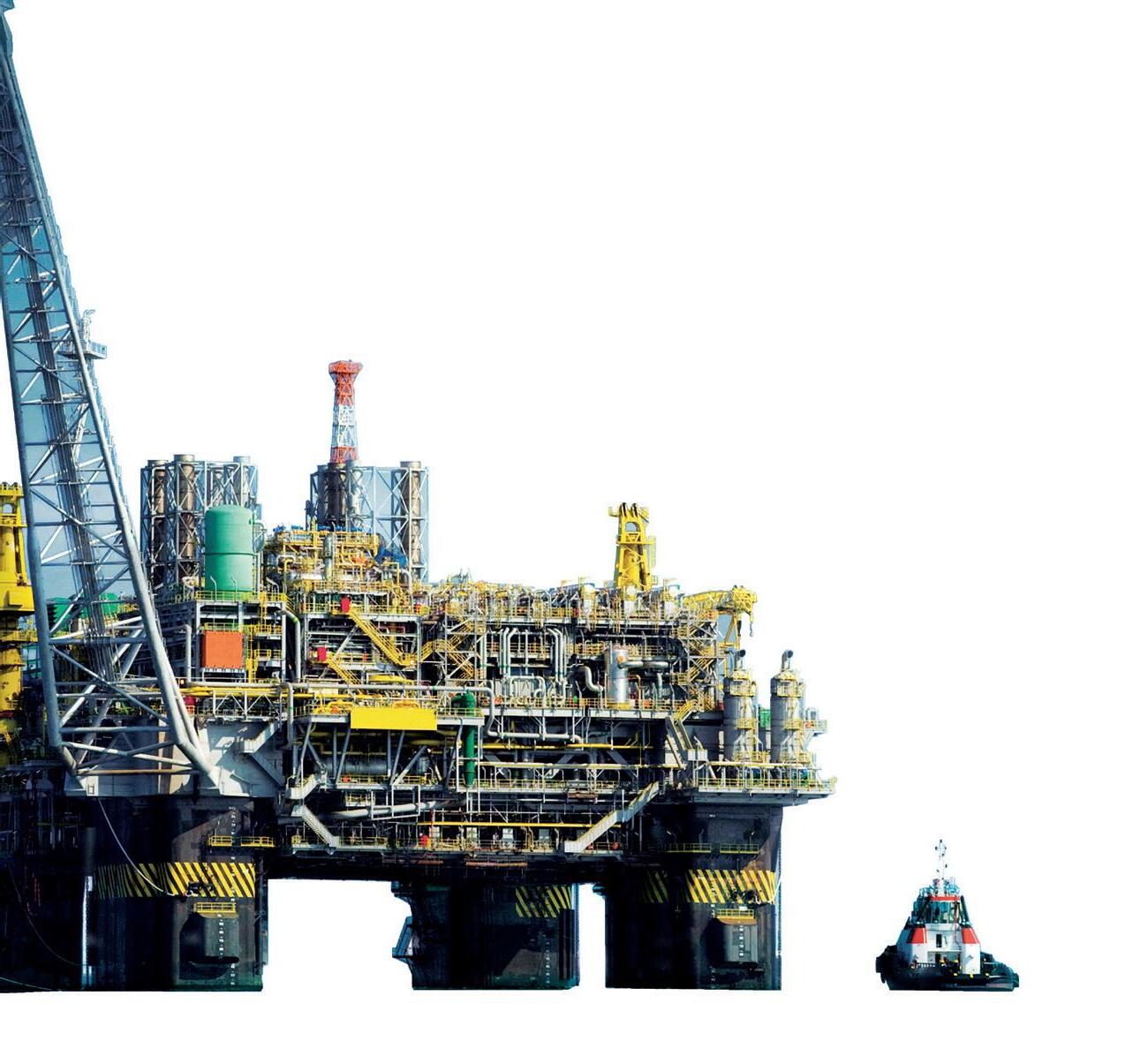
Innovative, efficient and compliant. That sums up the WEG W22 Ex series of hazardous motors.




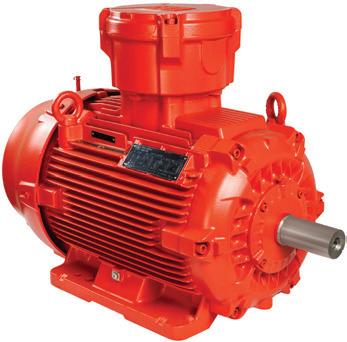
From small Low Voltage motors through to large High Voltage machines, our comprehensive ranges of Ex-d, Ex-nA, Ex-tb, Ex-tc and Ex-p motors comply to all the relevant IEC standards and are designed with reliability, efficiency and overall performance in mind.
For more information, please contact your local Sales Representative. www.weg.net/au
Motors | Automation | Energy | Transmission & Distribution | Coatings W22 Ex-d Flameproof. Ultimate Safety. Ultimate Efficiency.


