6 minute read
Decarbonisation: Land Ametek
Philippe Kerbois* and Neil Simpson**, Independent Consultant - Simpson Combustion & Energy Ltd, discuss how a glass manufacturer could start the decarbonisation journey to achieve a sustainable solution.
Note: This article is based on the presentation by Philippe Kerbois, and Neil Simpson presented in Istanbul on 18th November 2022 at the 37th Sisecam International Conference.
� Philippe Kerbois and Neil Simpson present their paper at the recent Sisecam conference in Istanbul.
While the end goal of decarbonisation may be known, it is key to establish the starting point of the journey in order to ensure that the correct path is taken to achieve a sustainable solution in the glass industry. Recent container and float glass case studies1 illustrate how Near Infrared (NIR) In-furnace Thermal Imaging surveys can show the current position. The output provided is best interpreted as a CFD model which can validate a digital twin. Typically, the initial process is to establish if the furnace thermal profile is optimised for the furnace design. Additionally, in parallel, any refractory hot/cold spots should be identified, and the top of the regenerators inspected. By utilising the patented reflection method, it is possible to show that the ‘mirror’ is, in fact, a micro-layer of foam which is insulating the heat transfer to the glass. Suppressing this foam can create energy cost savings in the region of up to six figures. By sealing the holes and reducing the parasitic air, operators can save 3-5% reduction in energy, plus a corresponding reduction in CO2. By starting with the low-hanging fruit, validating models, and defining a path from a known starting point, furnace operators know where they are starting from, even if destinations may change.
In February 2020 Simpson C&E had to cancel a Training Course in Singapore due to Covid. A bespoke online training course for one of the companies who had planned to attend identified that they had a new furnace, but the energy was significantly above budget by several hundred thousand. Due to Covid travel restrictions, engineers couldn’t travel to the location. However, the AMETEK Land NIR-Borescope-2K-Glass (NIR-B-2K-Glass) was sent to the location, and Global Field Service Engineer for Glass, Mark Briggs, provided online remote training to the site personnel on how to operate the equipment, while the customer engineering team made the physical measurements. The .erfx file data was transferred to Neil Simpson, who analysed

� Fig 1. Using the NIR-Borescope to review the peep-holes closest to the bridge wall

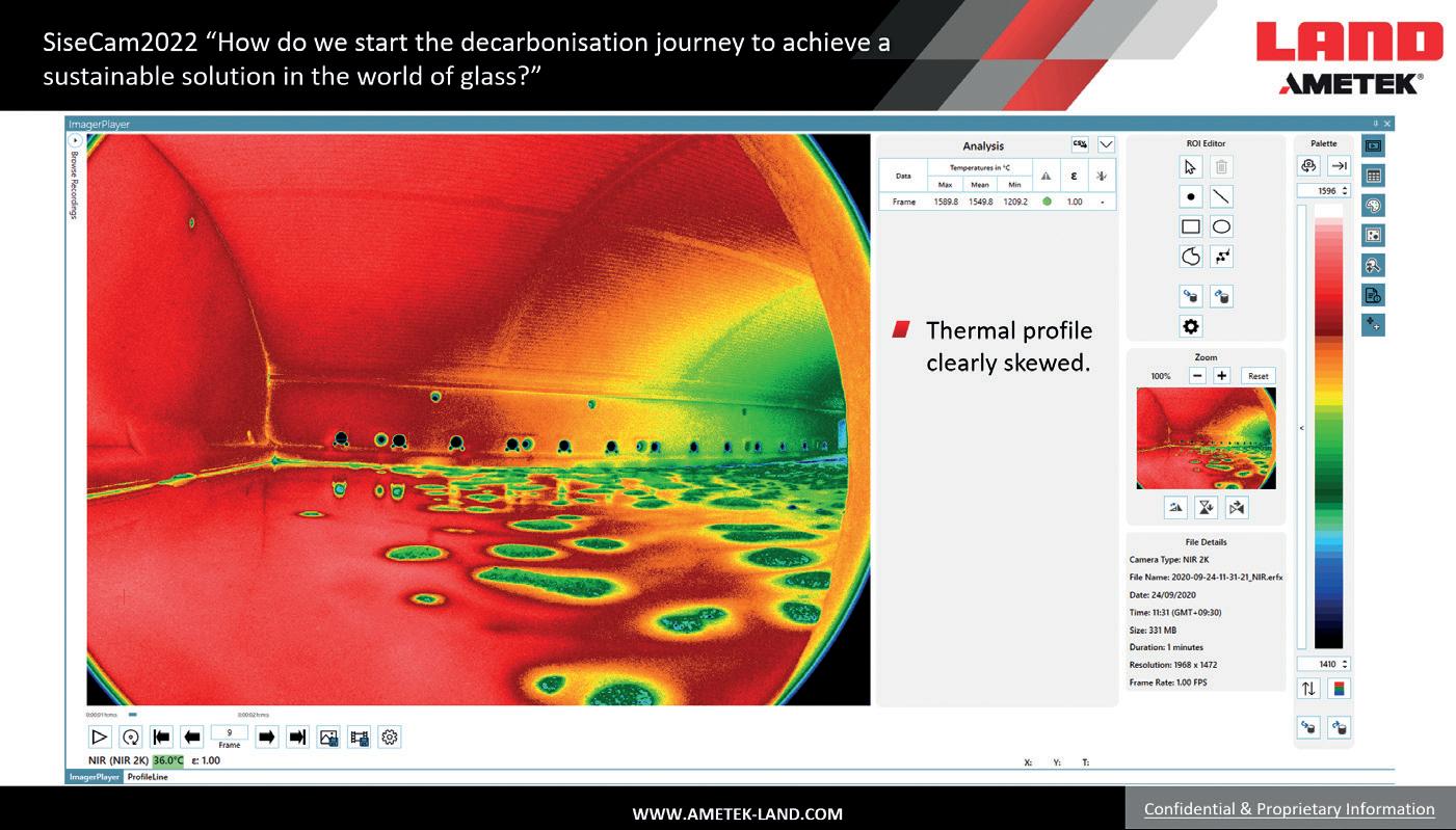
� Fig 2. Identification of pronounced skewing of the furnace profile. it remotely in Scotland. There was an opportunity to use the time difference to have an analysis done overnight. By the end of the second day, the majority of the peepholes had been analysed. An initial view of the front melt surface suggested there was an open mirror.
On the third day, the decision was made to make additional measurements on the peep-holes closest to the bridge wall (see Fig 1).
There was a pronounced skewing of the furnace profile (see Fig 2), but this was not sufficient to explain the high energy usage.
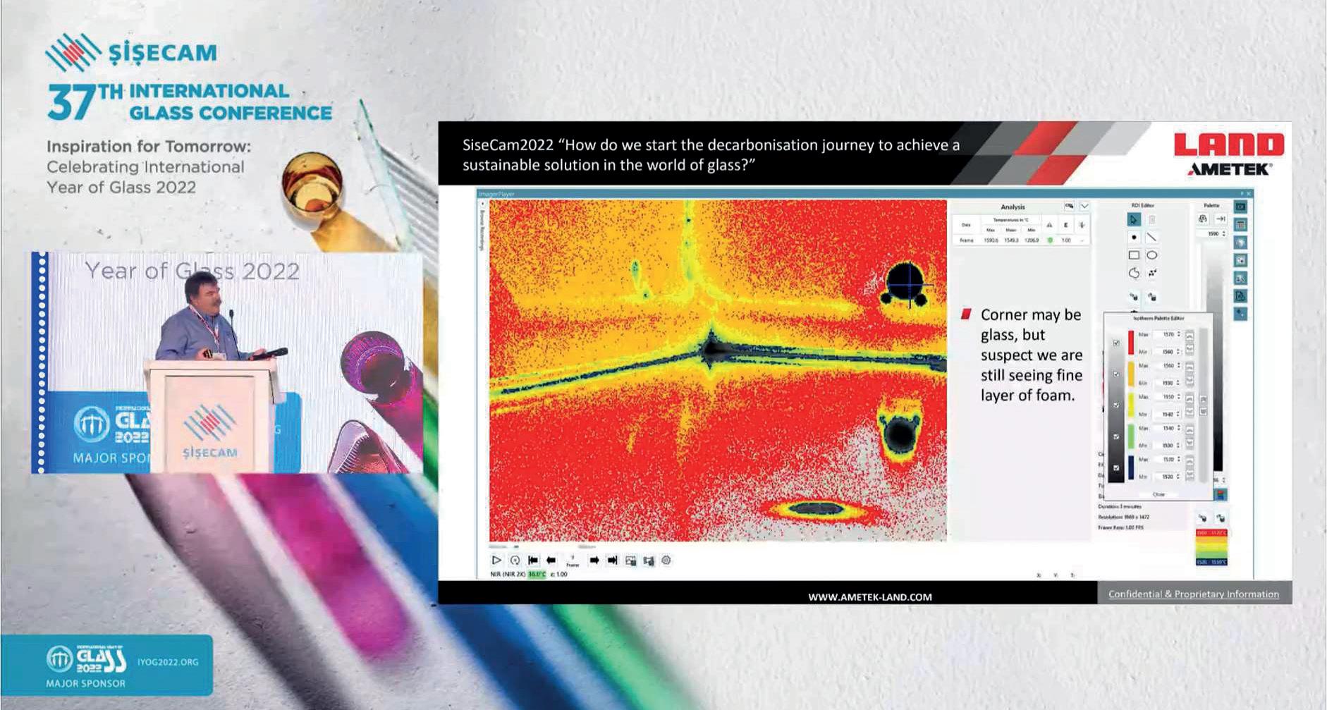
More detailed analysis of the images, and specifically the reflection on the glass surface, suggested that the surface temperature was too high to be open melt but was, in fact, caused by a micro-layer of foam which was reflecting the heat and not absorbing it (Fig 3).
Through a simple change in combustion, the foam layer was dispersed. The crown temperatures started to drop as the glass temperature started to rise, necessitating a reduction in energy. The budgeted energy and CO2 were achieved, with hundreds of thousands saved!
This example of using thermal imaging for troubleshooting poses the question of whether we really know how to optimise a furnace. Clearly, a thermal survey can be used as part of the process to identify and fix holes or over-cooling to save energy and CO2. By optimising flames and the thermal profile to suit furnace
� Fig 3. Identification and visualisation of foam on the glass surface.

throughput and improve yield a variance to the budget can be achieved. Permanently installing and integrating temperature data into an Industry 4.0 control system is also a great tool to help train, retrain and retain furnace personnel.
There are many lessons that can be learned from the past. Looking at a YouTube video which was made in 1950 to celebrate the 200th anniversary of making glass in O-I Alloa, UK an operator is seen using a disappearing fi lament pyrometer which was a forerunner of the Cyclops and the NIR-B-2K-Glass. Perhaps most relevant is the view of the Jubilee Furnace which was fi red using on-site producer gas from coal. The gas composition was 55% hydrogen, so it would suggest that 55% H2 fi ring will still be possible in the future.
Until 2028, there is the opportunity to recruit and develop process engineering personnel who can benefi t from the information provided by the NIR-B-2K-Glass. It will also validate existing CFD models to develop new furnaces for new fuels and oxidant sources to improve yield and energy to reduce CO2.
When it is understood what works and what the limits of operation are, alternative fuels and new furnace designs can be considered to achieve the 2050 decarbonisation goals.
Questions were raised following the presentation. Firstly, an academic asked if the technology existed to bring forward the 2050 goals to 2030.
The nature of the current furnace operation is to set a furnace life of 20 years in a fl oat furnace which makes the glass industry conservative to change. It is not unusual for it to take up to seven years for a glass company to accept a new technology. Rarely does anyone want to be fi rst to explore new methods.
Overall, new technical solutions will be found, but commercial challenges will likely be greater.
The second practical question was on which locations to consider installing a furnace camera on a fl oat furnace. There are pros and cons for every location. The optimum location may differ from a new furnace to an old one. There is negligible cost to make provision in a new furnace for a camera. It is possible to core drill an AZS refractory block and use the core as a plug for the future. It is easy to justify up to eight or more locations where you can use the NIR-B-2K-Glass. �
[1] Note: As part of the background case studies, reference was made to the following Glass Problems Conference Papers: � 2017 – Cross Fired Furnace Optimisation for Record Pull – Through furnace thermal profi le optimisation. � 2018 – End Fired Furnace NOx Emission Reduction – Through fl ame heat release analysis and regenerator optimisation � 2019 – Survey Tool and Glass Temp - Not Just a Pretty Picture – By identifying holes in refractory � 2020 - Supporting Hot and Cold Furnace repairs – By helping to fi x the holes and support heat-up and cool-down. � 2021 – In-Furnace Thermal Imaging Survey of a Float Furnace for Combustion Optimisation.

*Glass Industry Manager, AMETEK Land, land.enquiry@ametek.com. www.ametek-land.com
**Simpson Combustion secombustioncourse@gmail.com


