
6 minute read
Thermal E ects of Engineered Polymer Composite Ties on Track Gauge
Special Considerations for EPC Ties
Yin Gao, Principal Investigator I, MxV Rail
Since the early 2000s, MxV Rail has been evaluating the performance of engineered polymer composite (EPC) ties and working to improve design guidelines and recommendations as part of the Association of American Railroads (AAR) Strategic Research Initiatives (SRI) program. e EPC ties, which have been used at the Facility for Accelerated Service Testing (FAST) and in revenue service tracks for over two decades, are the most common type of composite ties, and they o er a potential alternative to solid sawn timber ties. e material used for EPC ties is especially attractive for use in regions where wood is susceptible to degradation by moisture and decay organisms.
However, recent research performed at FAST in Pueblo, CO, under the AAR SRI Program showed that track supported by EPC ties experienced more gauge widening variations due to temperature changes than track supported by wood ties. Speci cally, the track gauge for tracks with EPC ties was approximately 0.2 inch wider in the a ernoon than in the morning. Direct sunlight in the a ernoon can cause the top surface of the ties expand more than the other parts of the ties, thereby causing bending of the ties and widening of the track gauge. is article includes eld measurements that show the track gauge changes due to thermal in uence and presents the results of computer simulations that illustrate how thermal properties a ect EPC tie performance.
Field Investigation
In the fall of 2016, track gauge measurements were taken at di erent times throughout a single day at FAST using a track geometry inspection vehicle. Unloaded gauge measurements were taken on three EPC tie zones and wood/concrete tie zones in the same curve and using the same inspection vehicle. At the time of each test run, the tie temperatures were measured for one tie sample in each test zone. MxV Rail researchers measured tie temperatures at di erent locations on the ties’ tops and bottoms (measured from tie end and side). Ambient temperatures were recorded as well. e gauge measurement from the lowest tie temperature was recorded at 7:30 am, and the gauge measurement from the highest tie temperature was recorded at 2:00 pm.
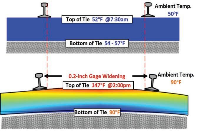
Figure 1 shows both the ambient temperature and the temperatures recorded at various locations on a tie at the coolest and warmest times of the day. e plot also supports the general observation that the bottom of the tie tends to remain insulated by both the tie itself and the crib ballast. e insulation e ect creates a thermal gradient and generates center negative bending. Linear expansion of the tie coupled with center negative bending resulted in about 0.2 inch of gauge widening—a measurement that was consistent between all three EPC tie zones. No measurable gauge increase was observed in the adjacent wood or concrete tie zones throughout the day.
Model Description
In-track gauge measurements indicated that EPC ties can expand under heat and generate measurable gauge widening. A nite element model was established to further investigate the thermal e ect on EPC ties.
e model included 1) two short pieces of rail, 2) two American Railway Engineering and Maintenance-of-Way Association (AREMA) 14-inch tie plates, 3) one EPC tie, and 4) a supporting ballast layer. e steady-state thermal analysis was used to model the e ects of steady thermal loads on the system and quantify the resultant gauge widening using structural analysis.
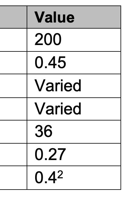
As shown in Figure 2, heat sources were applied both on the rails and on the top surface of the EPC tie (red area), excluding the tie plate area. e convection areas were all surfaces of all the components in the system. Because this was a preliminary study on the thermal e ect on the track gauge of EPC ties (not speci c to any type of tie), each model used the typical mechanical properties of each component, as listed in Table 1.
Modeling Results
Gauge widening was calculated by changing three parameters in eight simulation cases— coe cient of thermal expansion (CTE), thermal conductivity (TC), and temperature condition— as listed in Table 2. e CTE of 3.5×10⁻⁵ in./in./°F is the lowest value of the three types of EPC ties on the FAST track; the CTE of 5×10⁻⁵ in./in./°F is the average value of the three types of EPC ties on the FAST track; and the CTE of 7.5×10⁻⁵ in./ in./°F is the maximum allowable value in the AREMA Manual for Railway Engineering 4 e TC of 0.45 W/(m· C) is expected for high-density polyethylene,3 which is the typical EPC tie material; 1 and 10 W/(m· C) are considered high but reasonable TC values for polymer compounds.5
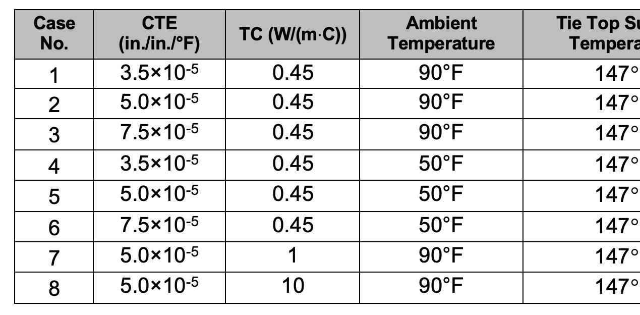
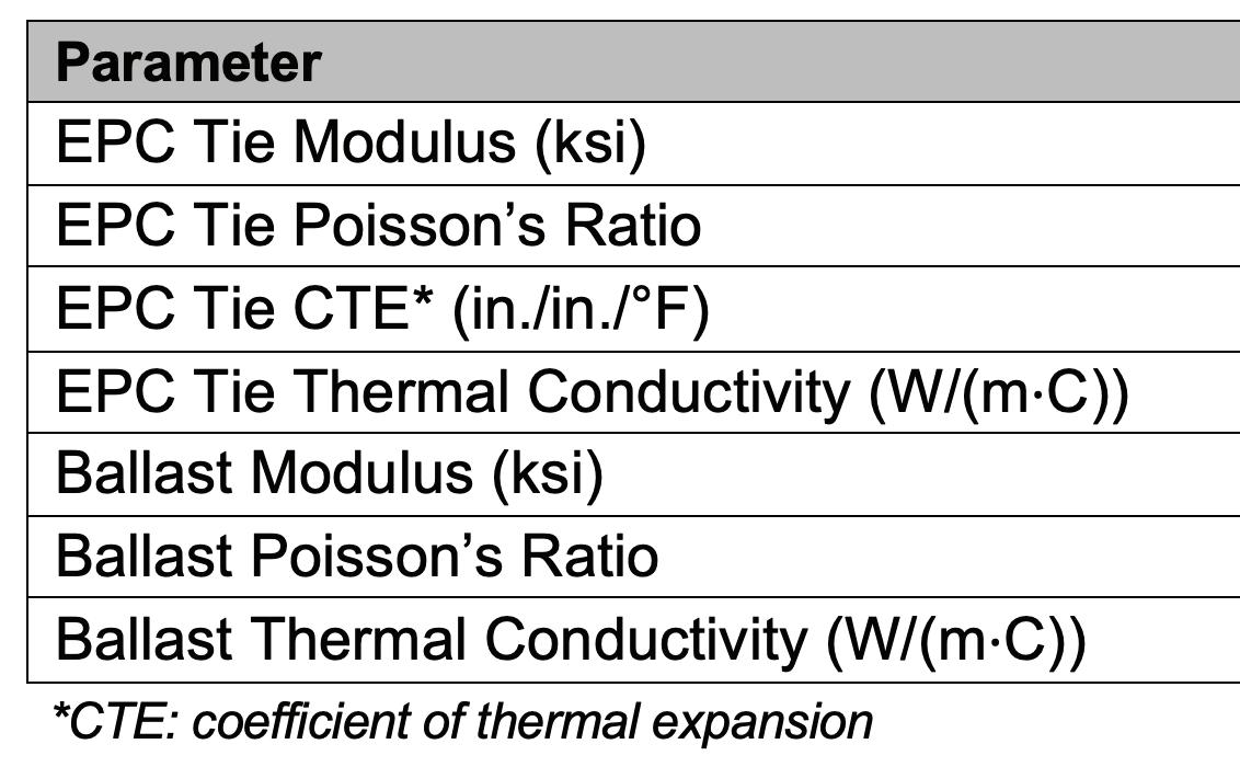
Table 2. Modeling parameters in simulation cases.
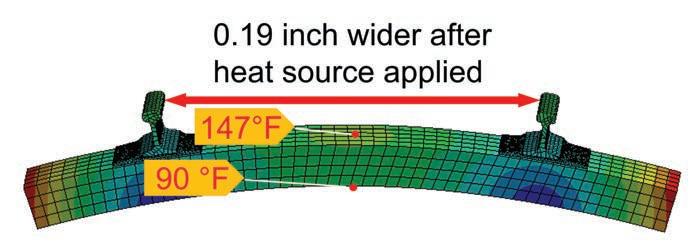
Cases 1, 2, and 3 were used to simulate the actual in-track temperature conditions in the FAST test for EPC ties with di erent CTEs. Cases 4, 5, and 6 represented extreme di erential temperatures between the top surface of a tie and the ambient temperature. Cases 7 and 8 increased the TC values using the parameters in Case 2 as a baseline. e in-track temperature and gauge widening measurements taken at FAST were used to verify the model. e CTE was assumed to be 5×10⁻⁵ in./in./ºF for all three types since each type showed a constant gage widening in the FAST test. e modeling results show a 0.19-inchwide gauge (Figure 4) that was close to the in-track measured value of 0.20 inch. e resulting temperatures on the tie’s bottom (93 ºF) closely matched the actual measurements (90 ºF).
For each simulation case, track gauge was rst calculated using a low-temperature condition with the ambient temperature and all components at 50 F and then using a high temperature condition (simulated direct sunshine on the tie tops), which is listed in Table 2 for each case. e gauge widening value for each simulation case was the di erence between the two track gauge values calculated above (Table 3).
According to Federal Railroad Administration’s (FRA) Track Safety Standards, the allowable gauge widening for Class 4 and 5 tracks is 1 inch. Based on the results, the gauge widening caused by the thermal e ect on EPC ties did not exceed the FRA standards. Track gauge widening can be the result of several superimposed causes, including 1) installation tolerances, 2) loading over time, 3) rail gauge face wear, 4) plate cutting/reverse rail cant, and 5) spike kill. If a Class 4 or 5 track is built at a 56.5-inch track gauge with EPC ties, the amount of classspeci c gauge widening may be reduced by at least 10 percent (Case 1) right a er construction and possibly more (29 percent in Case 6) for the tracks supported by EPC ties.
Comparing Case 1 to Case 6, two obvious and reasonable observations can be made:
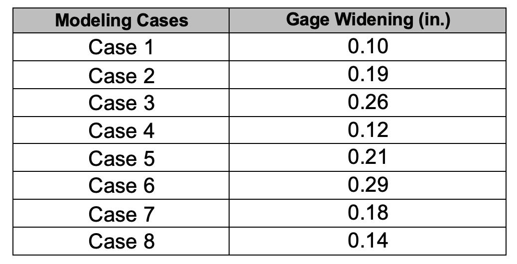
• e track gauge widened more as the CTE of EPC ties increased.
• e track gauge widened more as the di erential temperature between the top surfaces of the ties and the ambient temperature increased.
Cases 2, 7, and 8 showed decreased gauge widening with increased TC values. In ties with a higher TC, the temperature eld was more uniform, making the ties bend less. erefore, a higher TC could reduce the thermal e ect on the gauge widening of EPC ties.
Conclusions
A eld investigation was performed to measure the track gage variations of EPC ties. In addition, a nite element model was built by researchers at MxV Rail to investigate the thermal e ect on the performance of EPC ties. e results from this work showed:
• Field measurements taken at FAST showed a 0.2-inch track gauge widening (consistent between all three EPC tie zones) due to the temperature swing in one day.
• Track gauge widening ranges from 0.10 to 0.29 inch in the simulation cases that had changes in temperature cases, the coe cient of thermal expansion, and the thermal conductivity of EPC ties.
• e extent of the gauge widening in the modeling did not exceed the FRA safety standards for any track class, but the thermal gauge widening could reduce the amount of gauge widening from other causes without altering the track class.
• e amount of gauge widening is predicted to be less when using EPC ties with a higher thermal conductivity.
Acknowledgement
MxV Rail gratefully acknowledges the support from the Association of American Railroads Strategic Research Initiatives Program – Tie and Fastener Systems.
References
1. McHenry, M., Y. Gao, and J. Baillargeon, 2018, “Implementing Improved Composite Tie Design and Testing Guidelines into the AREMA Manual for Railway Engineering,” Proceedings, 2018 Annual AREMA Conference.
2. Engineering ToolBox. ermal Conductivity of selected Materials and Gases. Available at: https://www.engineeringtoolbox.com/thermal-conductivity-d_429.html [Accessed January 28th, 2023].
3. Santa, G., F. Peron, A. Galgaro, M. Cultrera, D. Bertermann, J. Mueller, and A. Bernardi. 2017. “Laboratory Measurements of Gravel ermal Conductivity: An Update Methodological Approach.” Energy Procedia, Volume 125, Pages 671-677.
4. Manual for Railway Engineering, Chapter 30 – Ties, 2022
5. Grundler, M., T. Derieth and A. Heinzel, 2016, “Polymer Compounds with High ermal Conductivity.” 2016 AIP Conference Proceedings 1724, 020049.


