Exodraft installation guide for Rais Gas.
If the flue cannot stay within the maximum guide lengths it may be a solution to install an Exodraft smoke extractor. This guide will go through the assembly of Exodraft smoke extractor on a Rais gas fire.
Installation must be performed by an authorized electrician and an authorized gas plumber. Note: This document may only be used as a guide. If any doubt contact your Exodraft dealer. The guide only covers the overall view of the assembly procedure, for the installation procedure, follow the Exodraft installation manual.
Model:
RHGC
Due to the design, it is possible to install a RHGC exodraft smoke extractor on horizontal as well as vertical smoke ducts with many bends. However, the length of the flue may be Min. 5 meters and Max. 60 meters, with 15 pcs. bends of 90 degrees. The smoke extractor provides optimal draft in the flue in all weather conditions. With constant flow monitoring and automatic shut-down in accordance with the Gas Directive.
RHGC is made for concentric LAS chimney systems, where the flue gases from the gas fireplace are drawn out of the chimney, at the same time as the fireplace is supplied with fresh combustion air.

EXODRAFT / RAIS GB 1 - GB NSN 2022

EXODRAFT / RAIS 2 - GB NSN 2022 GB Installation overview EFC21
Installation example overview

EXODRAFT / RAIS GB 3 - GB NSN 2022
Relay for receiver connected to the EFC21

Wiring positions to the EFC21 can be seen on Figure 1-2 - page 12
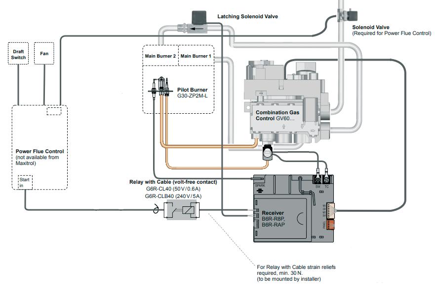
Position Q - External start
Position 8 & 9
Relay for receiver
Connect the Relay to the “Relay” port on the left side of the receiver.
EXODRAFT / RAIS 4 - GB NSN 2022 GB
EFC21
Relay for receiver connected to the EFC21
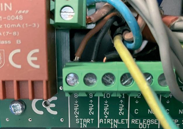
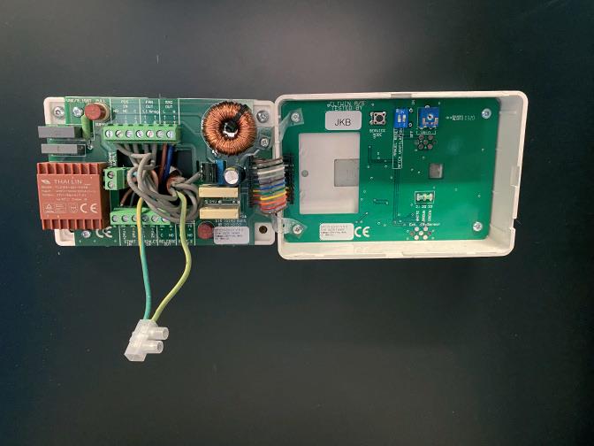
Wiring positions to the EFC21 can be seen on Figure 1-2 - page 12
Position Q - External start
Position 8 & 9
EFC21
Relay to EFC21
Connect the brown wire to port 8
Connect the black wire to port 9
EXODRAFT / RAIS GB 5 - GB NSN 2022
Solenoid valve placement


Wiring positions to the EFC21 can be seen on Figure 1-2 - page 12
Position G - Solenoid (SMG)
Position 6 & 7
We recommend Exodraft SMG14 1/4 up to 10kW fireplaces and Exodraft SMG 12 1/2 from 10kW and upward. The solenoid valve may be placed a maximum of 1 meter from the GV60 gas valve
EXODRAFT / RAIS 6 - GB NSN 2022 GB
The solenoid is connected on the gas inlet to the GV60 gas control valve. The solenoid shall be connected to the EFC21 port 6 and 7.
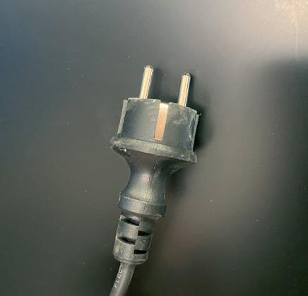
Power supply for the EFC21

Wiring positions to the EFC21 can be seen on Figure 1-2 - page 12
Position R - 230VAC
Position N & L
EXODRAFT / RAIS GB 7 - GB NSN 2022
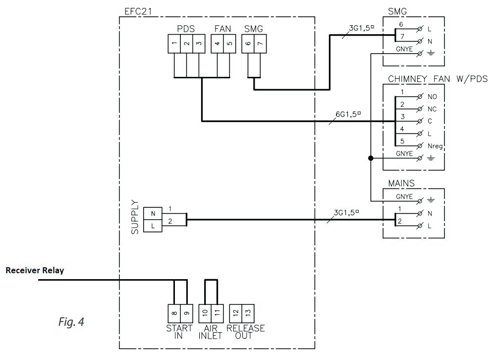
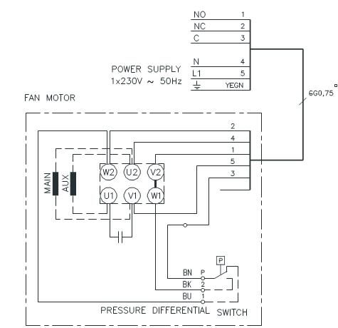
From RHGC trough the isolation switch to the EFC21 Wiring positions to the EFC21 can be seen on Figure 3 - page 13
Position E - Pressostat - 1,2 & 3

Position F - Fan 4 & 5
Please note that Exodraft fans require extra safeguards in accordance with current power regulations. It should be possible to shut down the RHGC from the outside while doing service/installation on the system using a isolation switch or safety switch from Exodraft.

The RHGC is equipped with 5 grey wires marked from 1-5. The wires should be installed in the order described on figure 3 page 13

EXODRAFT / RAIS 8 - GB NSN 2022 GB
Start - Fan motor (Under the Fan cover)
End - EFC21
Fan Motor Wiring
Pressostat wiring
Check that the blue, black and brown wires are connected as the picture below. Check that the rubber pipes are connected.
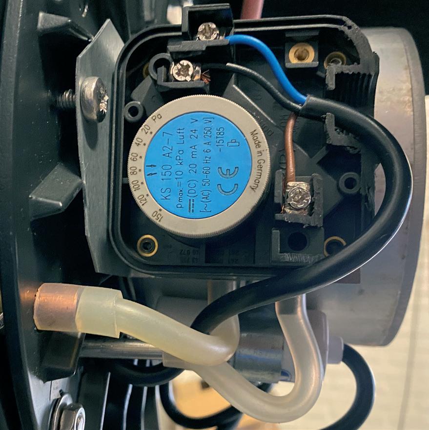
The pressostat is placed under the cover of the fan.

EXODRAFT / RAIS GB 9 - GB NSN 2022
Pressostat
First start up and adjustment
When doing commissioning all windows and doors must be closed prior to commissioning. If there is another form of ventilation in the room, it should be run at full speed during the commissioning.
Before the test, the speed of the fan most be determined and adjusted. The adjustment should be done on the back side of the EFC21 at position K - See figure 2 on page 12. Fan speed it determined by lighting the fire and adjusting the speed of the Fan by looking at the flame picture. The flame picture most be calm and flame colour blue in the beginning at light yellow before 10minutes burning time. At shut-off make sure that no gas leakage is detected, if so, speed should be increased.
Commissioning is carried out with the control box open. Only touch components with electrically insulated tools.
DIP Switch settings
We recommend to put the Manual Reset on “On” (position 1) and the After Ventilation to “ON” (position 1).
1) Service Mode
- Open the control panel (EFC21)
- Press ON/OFF button on the front of the EFC21 panel
- Turn on the fireplace - Wait until the light turns green (not flashing)
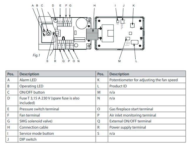
- Press the service mode button (figure 1 position I)
- Alarm LED (figure 3 position A) will flash RED
- Operating LED (figure 3 position B) will flash according to the pressure switch position

EXODRAFT / RAIS 10 - GB NSN 2022 GB
2) Setting the pressure switch
To set the pressure switch, remove the Fan cover.
Set the pressure switch to a minimum by turning anti-clockwise.
- Slowly increase the pressure switch setting until it cuts out (you will hear a click) or until the Operating LED (figure 4 position B) changes from GREEN to RED.
- Make a note of the pressure switch setting at cut-off.
- Set the pressure switch to 10 Pa below the previously noted cut-off value.
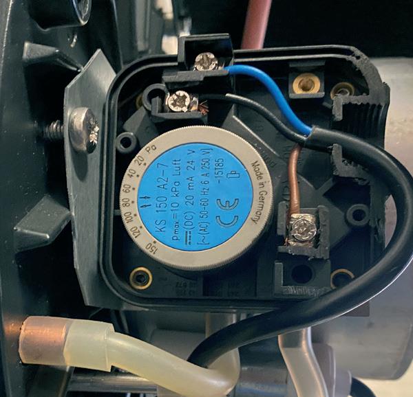
- Press ON/OFF button on the front of the EFC21 panel (figure 4 position A). Service mode is now deactivated.
3) Testing the setup
- Press ON/OFF button on the front of the EFC21 panel (figure 4 position A).

- Start the fireplace.
- Check there is no leakage from the combustion chamber.

- If a leak is detected start the adjustment from the beginning.
- After running for ten minutes with no leakage, turn the isolation switch off and the fail-safe function is being checked. The fireplace should cut-out after 15 seconds after the pressure switch has cut-off. Remember to switch the isolation switch back on.
- Fit the cover.
Operating LED
EXODRAFT / RAIS GB 11 - GB NSN 2022
Alarm LED On/Off
Figure 4


EXODRAFT / RAIS 12 - GB NSN 2022 GB
Wiring diagram EFC21
Figure 1
Internal EFC21 overview
Figure 2
EXODRAFT / RAIS GB 13 - GB NSN 2022
Fan to EFC21 wiring diagram
Figure 3


