ASSEMBLY INSTRUCTIONS - FLUE PIPE INSTALLATIONS FOR GAS FIREPLACES

DK - 1
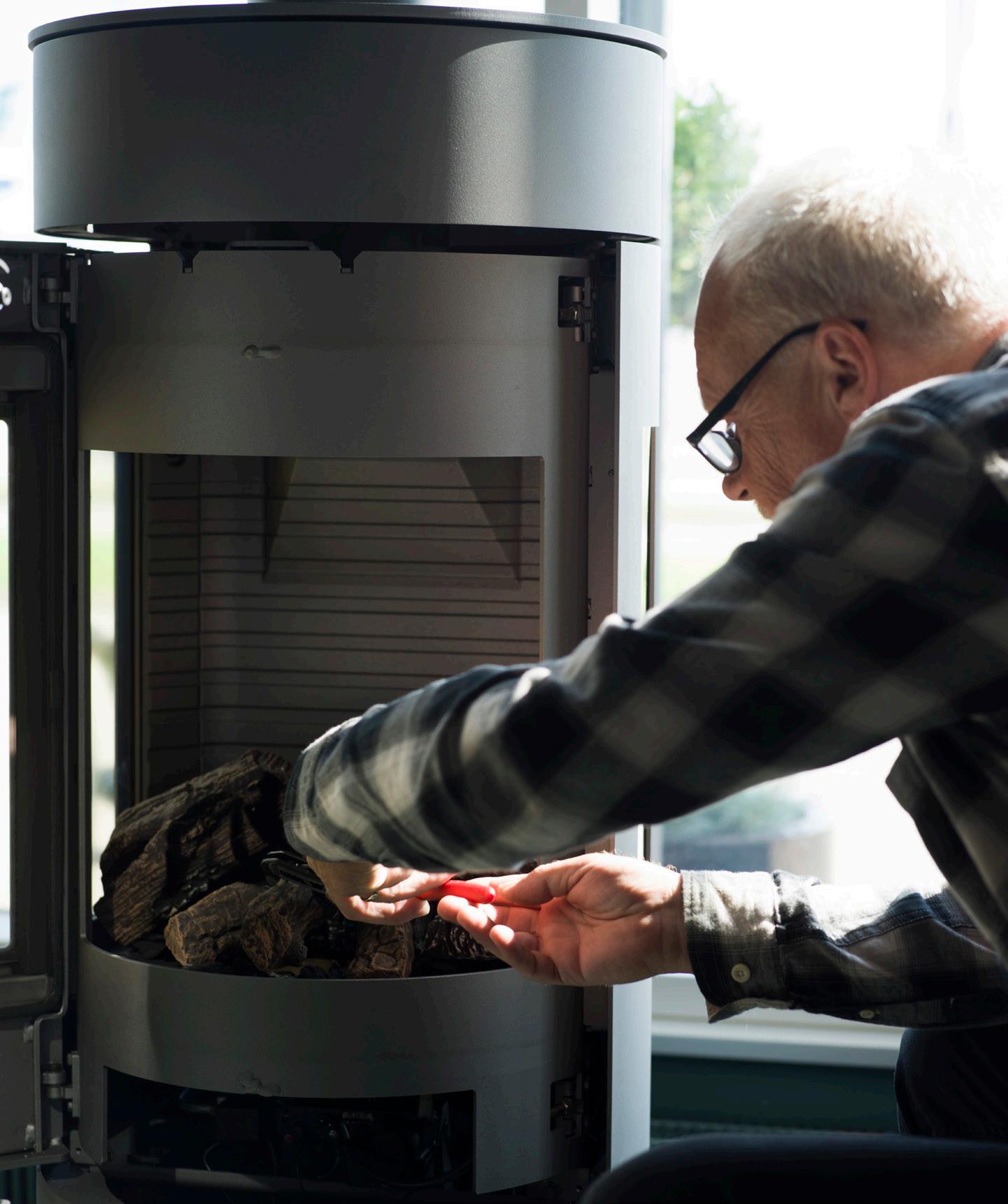
GENERAL INFORMATION
GENERAL INFORMATION
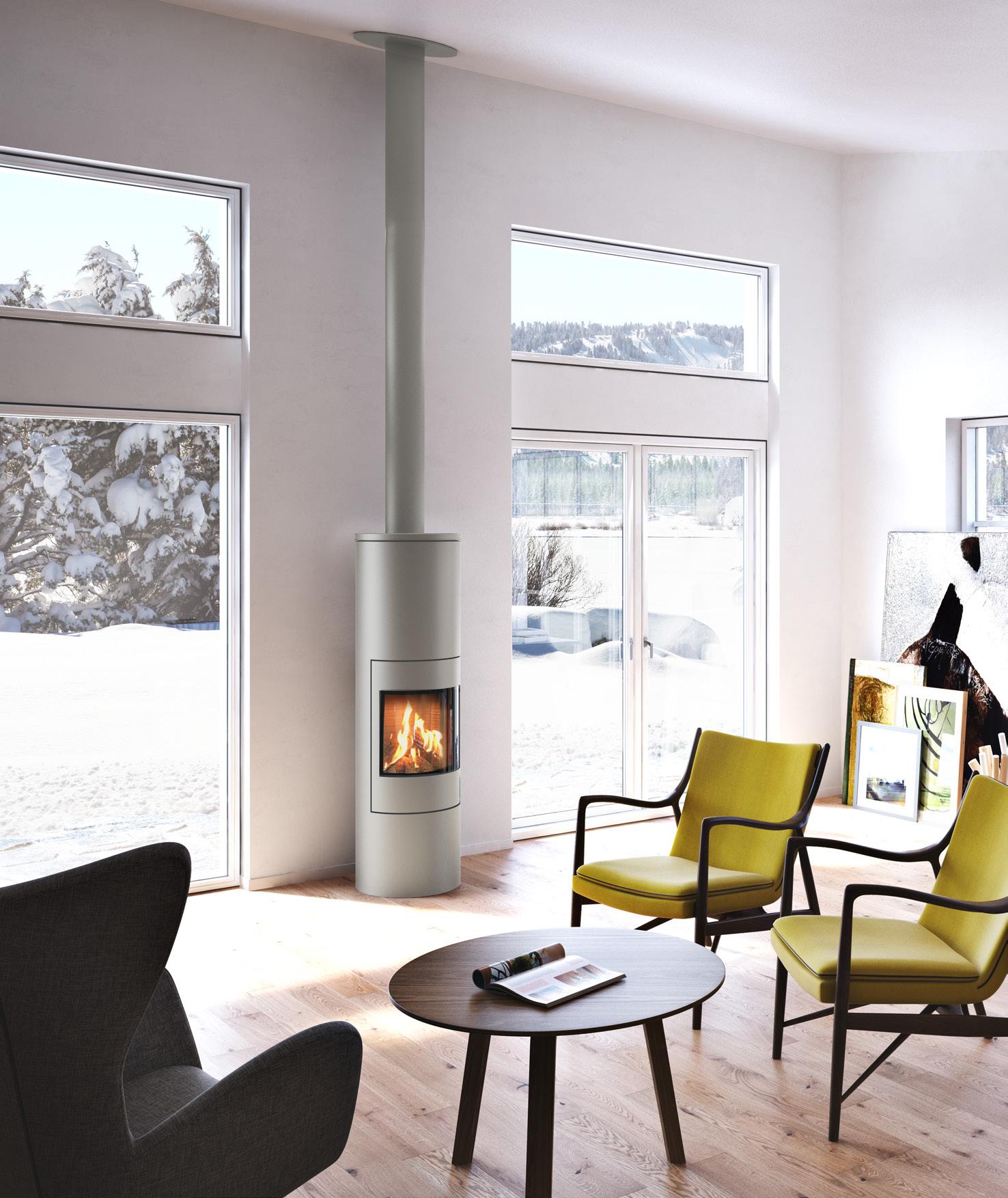
These assembly instructions describe how to connect a gas fireplace to a balanced flue, i.e. a flue that consists of two pipes, one inside the other (also called a concentric flue). The outer pipe draws fresh air in from outside for combustion, while the exhaust gases are removed through the inner pipe.
These instructions are based on five different flue solutions for a gas fireplace. The five solutions are:
• Flue system using an existing chimney
• Flue system through a roof
• Flue system through a wall
• Flue system up along wall
• Flue system through a snorkel terminal
There are a great many variations of these five solutions.
The solutions are divided into two types – assembly instructions using US pipe and assembly instructions using USD pipe.
US pipe is our “general” pipe, which is especially used for solutions where the flue pipes are not visible. They are assembled using pipe clamps and are available in black and stainless steel.
USD pipe (also called “design pipe”), is often used for solutions where the flue pipes are visible. The pipes are pushed in against each other and have almost invisible joints. The pipes are available in different RAIS colours and a smooth pipe clamp is also available.
The instructions show the main principle of the flue solution using a complete drawing, followed by the individual details with an explanation of how the individual sections are assembled.
DIMENSIONS AND APPROVED LABELS
The flue pipes are available in two different dimensions: Ø100/150 (product numbers end in 10) and Ø130/200 (product numbers end 13).
RAIS/ATTIKA recommends that the fireplace is fitted with the following flue make: OnTop Metaloterm USD or OnTop Metaloterm US. Other approved flue system manufacturers are: Jeremias, Muelink & Grol and Poujoulat PGI.
These user instructions are based on Metaloterm’s flue pipe, which can be used directly in the gas fireplace without a start section.
GB 2 - GB
Balanced flue system using an existing chimney US pipe 4 USD pipe 12 Balanced flue system through a roof US pipe 20 USD pipe 28 Balanced flue system through a wall US pipe 36 USD pipe 42 Balanced flue system up along a wall US pipe and USD pipe 48 Balanced flue system through a snorkel terminal US pipe and USD pipe 60 Power fan - fan solution for long flue 68 CONTENTS GB GB - 3
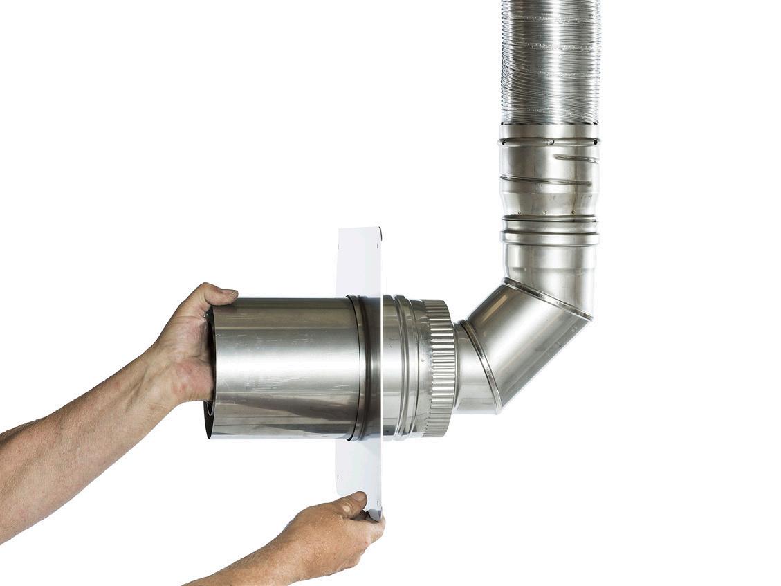
BALANCED FLUE SYSTEM USING AN EXISTING CHIMNEY (RENOVATION DRAWING)
US PIPE
In this section, you will learn how to install a balanced flue system through an existing chimney using US pipe. The examples are shown with pipe dimension Ø100/150 – the pipes are also available in dimension Ø130/200 (product numbers end in 13). NB: When using pipe dimension Ø130/200, the clearing must be at least Ø200.
USDVC2 10: AIR INTAKE AND EXHAUST GASES COWL
See explanation 7
USSAN1: COVERING AND TRANSITION FOR DOUBLE PIPE
See explanation 6
X AC 10: TRANSITION FROM FLEXIBLE HOSE TO SINGLE PIPE
See explanation 5
XE: FLEXIBLE HOSE, 10 m
See explanation 4
XA 10: TRANSITION FOR FLEXIBLE HOSE
See explanation 3
USSAN2: TRANSITION FROM CONCENTRIC PIPE TO SINGLE PIPE
See explanation 2
US 100/50/25: FLUE PIPE
See explanation 1
NB!
Option for horizontal pipework and direction changes with bends (USB 90/45/30/20/15) also available.
See page 36 for explanation.
GB 4 - GB
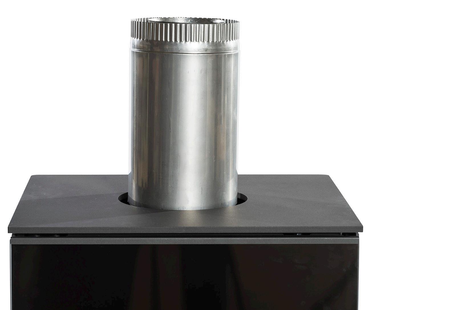
EXPLANATION 1: FLUE PIPE (US 100/50/25)

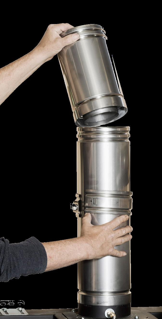
FLUE PIPE (US 100/50/25)
With free-standing gas fireplaces, fit a pipe with measuring points (USEM 10).
Fit the flue pipe with the end with a single groove down towards the fireplace.
Always assemble with a pipe clamp (USKB)
GB GB - 5
EXPLANATION 2: RENOVATION SET (BASE) (USSAN2)
RENOVATION SET (BASE) (USSAN2)
Can be fitted both horizontally and vertically.
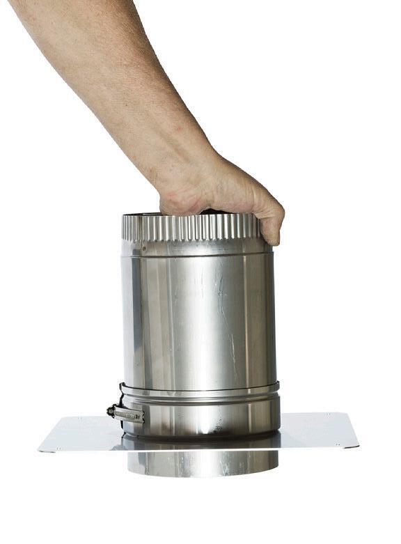
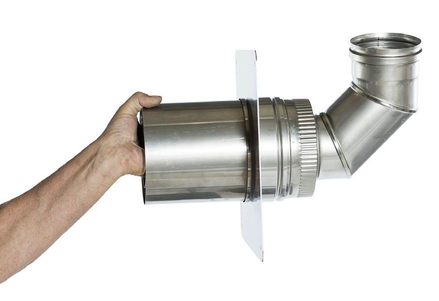 Plate for fitting on wall. Seal with sealant or with gasket.
GB 6 - GB
Bend inside chimney (MEB 90 10)
EXPLANATION 3: TRANSITION PIPE (BOTTOM) (XA 10) FROM US PIPE TO FLEXIBLE HOSE
TRANSITION PIPE (BOTTOM) (XA 10) FROM US PIPE TO FLEXIBLE HOSE
Flexible hose, 10 m (XE 1010)
Transition for flexible hose in chimney (XA 10)
Fit the flexible hose in XA 10.
Bend for easy fitting to flexible hose (MEB 90 10)
GB GB - 7
EXPLANATION 4: FLEXIBLE HOSE (XE 10 10)
FLEXIBLE HOSE (XE 10 10)
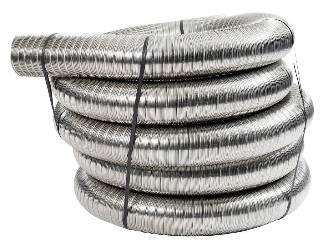
Available in a box with 10 m. If 10 m is not enough, more flexible hose can be joined together using an X AK 10.
Cut the flexible hose (XE 10 10) to a suitable length.
GB 8 - GB
EXPLANATION 5: TRANSITION PIPE (X AC) IN TOP OF THE CHIMNEY FROM THE FLEXIBLE HOSE TO US PIPE.
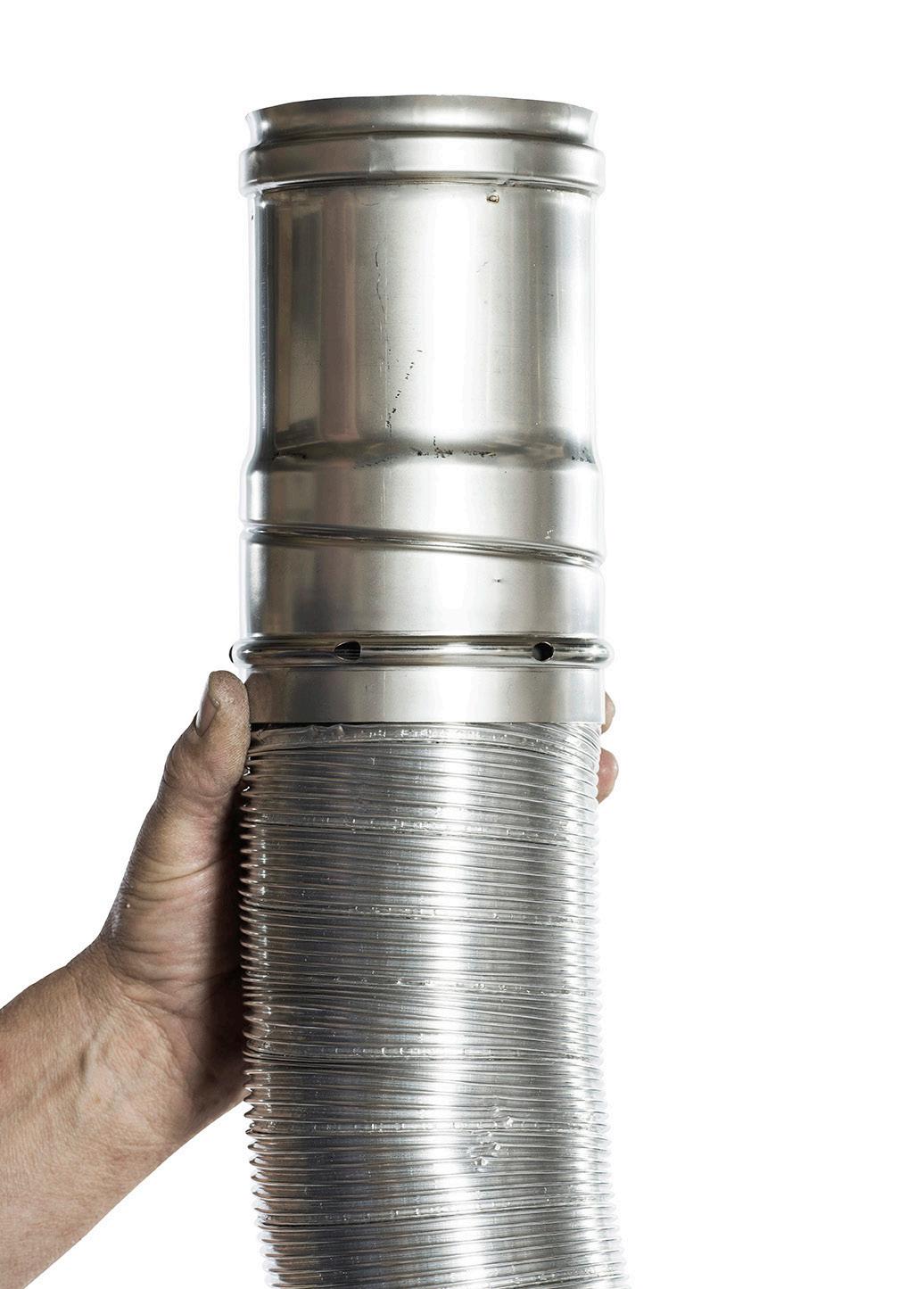
TRANSITION PIPE (X AC) IN TOP OF THE CHIMNEY FROM THE FLEXIBLE HOSE TO US PIPE
Push the flexible hose (XE 10 10) inside the transition pipe (X AC) and it will lock securely.
GB GB - 9
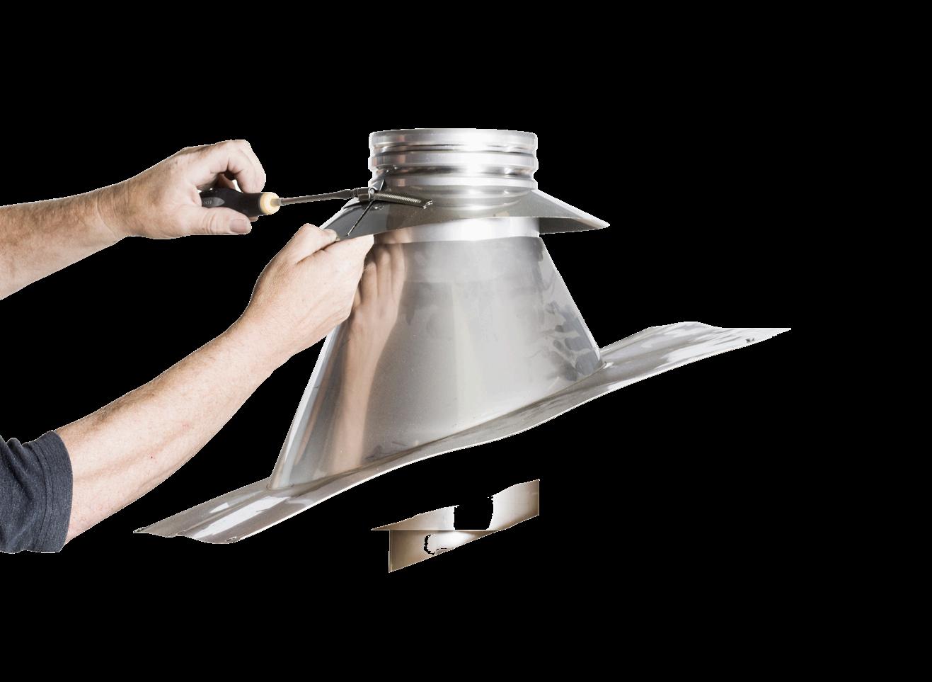
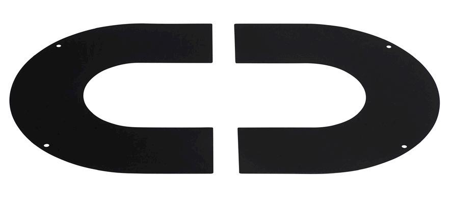
EXPLANATION 6: TRANSITION FOR DOUBLE PIPE IN TOP OF CHIMNEY (USSAN1)
TRANSITION FOR DOUBLE PIPE IN TOP OF CHIMNEY (USSAN1)
Split flue for fitting in brick chimney. This flue is a double pipe in the top and bottom. The hose is for exhaust gases and the cavity around the hose is for the intake of fresh air.
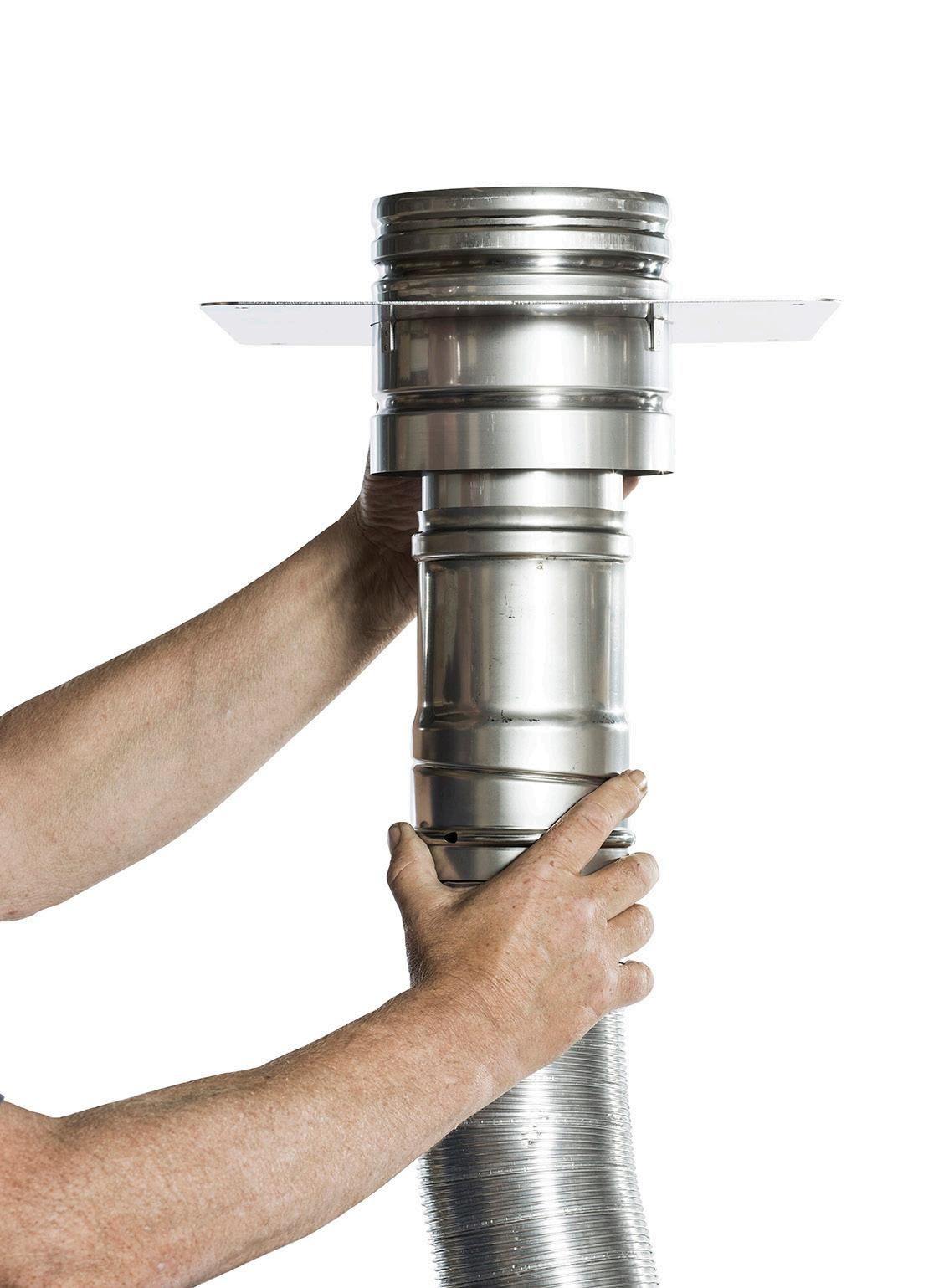
Transition for double pipe in top of chimney (USSAN1)
Secure the plate to the chimney top and fully seal it with sealant.
Transition for flexible hose in top (X AC)
GB 10 - GB
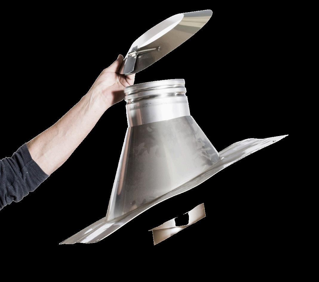
EXPLANATION 7: EXHAUST GASES COWL AND AIR INTAKE COWL (USDVC2 10)
EXHAUST GASES COWL AND AIR INTAKE COWL (USDVC2 10)
Available in black or stainless steel.
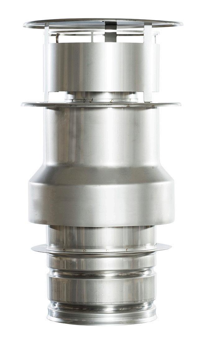
Exhaust gases cowl and air intake cowl (USDVC2)
Fit using a pipe clamp (USKB)
GB GB - 11
BALANCED FLUE SYSTEM USING AN EXISTING CHIMNEY (RENOVATION DRAWING)
USD PIPE
In this section, you will learn how to install a balanced flue system through an existing chimney using USD pipe. The examples are shown with pipe dimension Ø100/150 – the pipes are also available in dimension Ø130/200 (product numbers end in 13). NB: When using pipe dimension Ø130/200, the clearing must be at least Ø200.
USDVC2 10: AIR INTAKE AND EXHAUST GASES COWL
See explanation 7
USSAN1: COVERING AND TRANSITION FOR DOUBLE PIPE
See explanation 6
X AC 10: TRANSITION FROM FLEXIBLE HOSE TO SINGLE PIPE
See explanation 5
NB!
Option for transition from USD pipe US pipe using adaptor (USDO) is also available.
XE: FLEXIBLE HOSE, 10 m
See explanation 4
XA 10: TRANSITION FOR FLEXIBLE HOSE
See explanation 3
USSAN2: TRANSITION FROM CONCENTRIC PIPE TO SINGLE PIPE
See explanation 2
USD 100/50/25: FLUE PIPE
See explanation 1
NB!
Option for horizontal pipework and direction changes with bends (USDB 90/45/30/20/15) also available. See page 42 for explanation.
GB 12 - GB
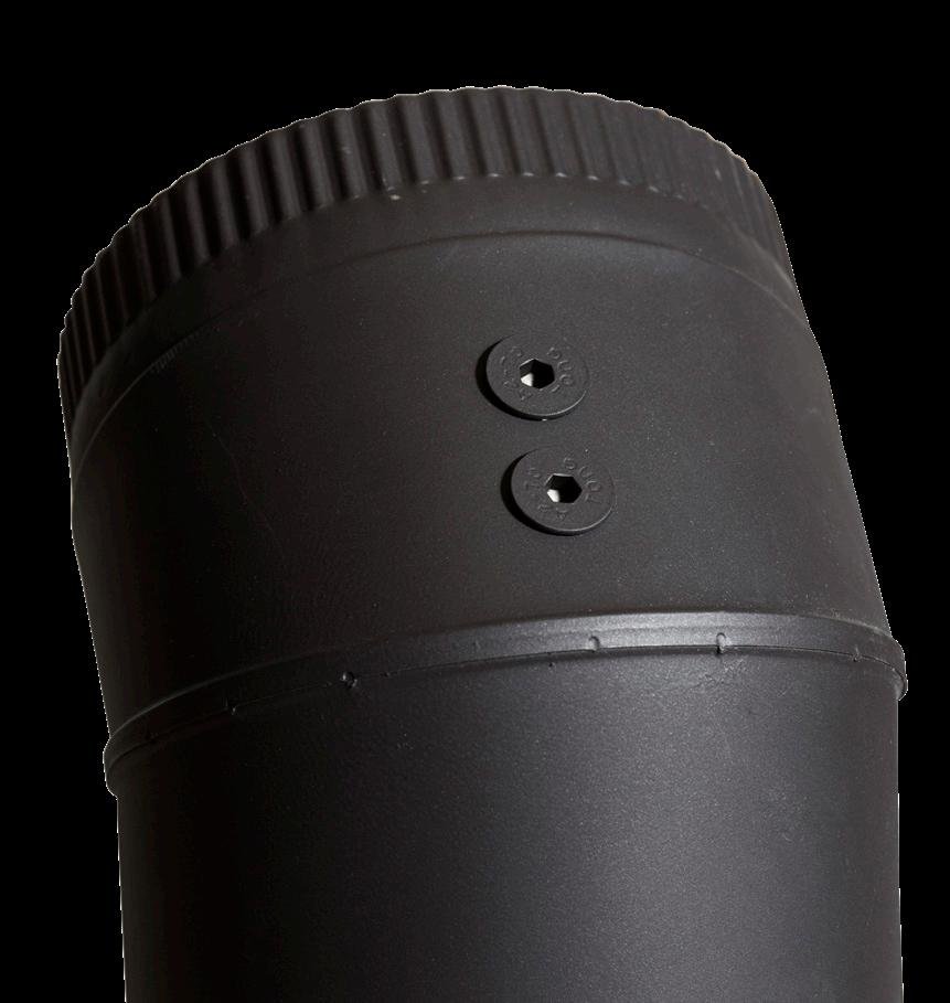
EXPLANATION 1: FLUE PIPE (USD 100/50/25) – “DESIGN PIPE”
FLUE PIPE (USD 100/50/25) – “DESIGN PIPE”
Available in six RAIS colours. When using USD pipe for free-standing gas fireplaces, you must always use a pipe with a measuring point. The measuring point may not be positioned in against the wall – there must be enough space to take readings.
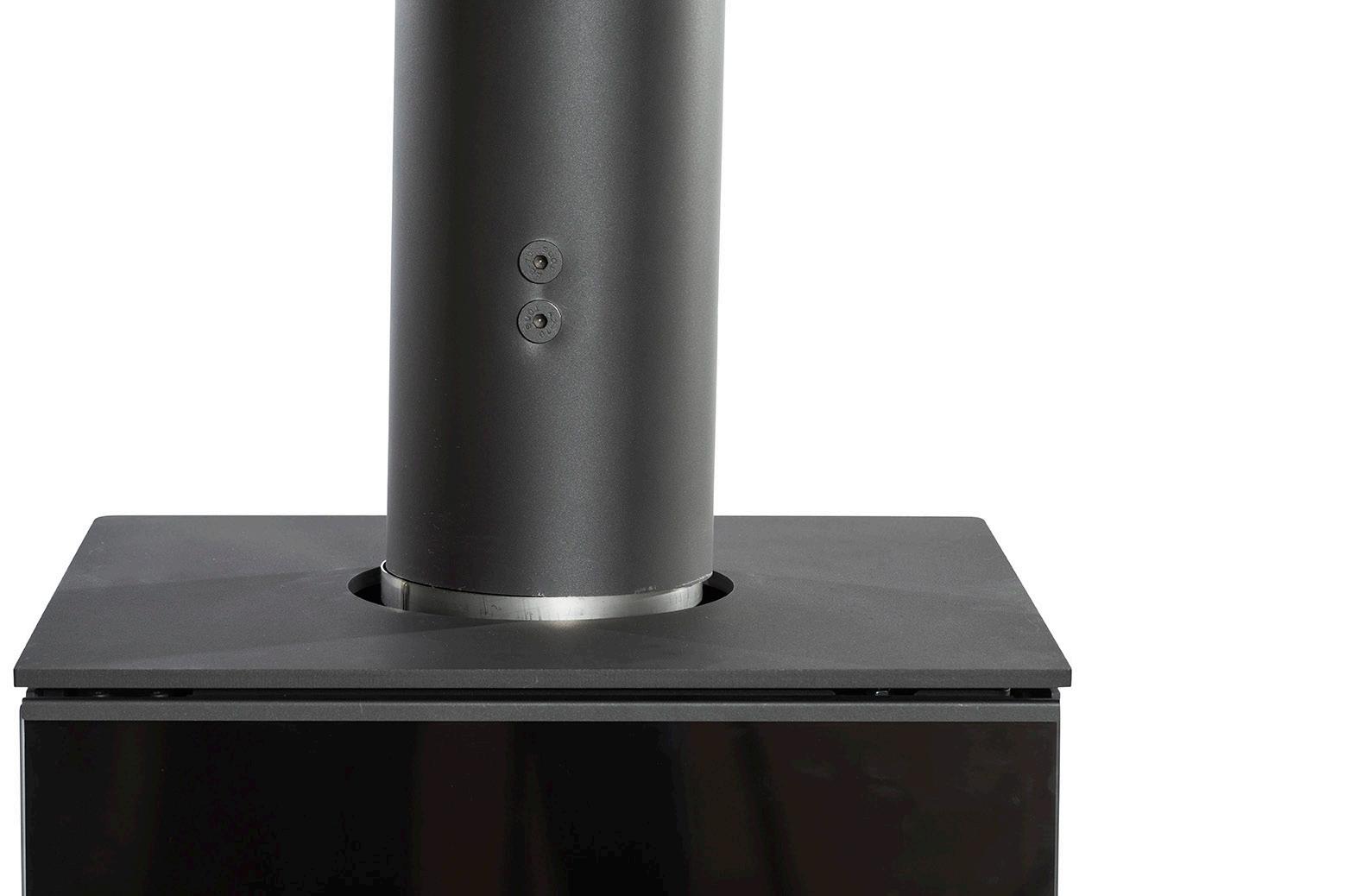

Fit the smooth end down in the fireplace. Next, push the pipes together so that the joints are almost invisible.
OBS: A smooth pipe clamp is also available for USD pipe.
Measuring point
GB GB - 13
EXPLANATION 2: RENOVATION SET (BASE) (USSAN2)
RENOVATION SET (BASE) (USSAN2)
Available in six RAIS colours. Can be fitted both horizontally and vertically.
Plate for fitting on wall. Seal with sealant or with gasket.
GB 14 - GB
Bend inside chimney (MEB 90 10)
EXPLANATION 3: TRANSITION PIPE (BOTTOM) (XA 10) FROM US PIPE TO FLEXIBLE HOSE
TRANSITION PIPE (BOTTOM) (XA 10) FROM US PIPE TO FLEXIBLE HOSE
Flexible hose, 10 m (XE 1010)
Transition for flexible hose in chimney (XA 10)
Fit the flexible hose in XA 10.
Bend for easy fitting to flexible hose (MEB 90 10)
GB GB - 15
EXPLANATION 4: FLEXIBLE HOSE (XE 10 10)
FLEXIBLE HOSE (XE 10 10)
Available in a box with 10 m. If 10 m is not enough, more flexible hose can be joined together using an X AK 10.
Cut the flexible hose (XE 10 10) to a suitable length.
GB 16 - GB
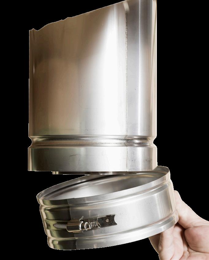
EXPLANATION 5: TRANSITION PIPE (X AC) IN TOP OF THE CHIMNEY FROM THE FLEXIBLE HOSE TO US PIPE
TRANSITION PIPE (X AC) IN TOP OF THE CHIMNEY FROM THE FLEXIBLE HOSE TO US PIPE.
Push the flexible hose (XE 10 10) inside the transition pipe (X AC) and it will lock securely.
GB GB - 17
EXPLANATION 6: TRANSITION FOR DOUBLE PIPE IN TOP OF CHIMNEY (USSAN1)
TRANSITION FOR DOUBLE PIPE IN TOP OF CHIMNEY (USSAN1)
Split flue for fitting in brick chimney. This flue is a double pipe in the top and bottom. The hose is for exhaust gases and the cavity around the hose is for the intake of fresh air.
Transition for double pipe in top of chimney (USSAN1)
Secure the plate to the chimney top and fully seal it with sealant.
Transition for flexible hose in top (X AC)
GB 18 - GB
EXPLANATION 7: EXHAUST GASES COWL AND AIR INTAKE COWL (USDVC2 10)
EXHAUST GASES COWL AND AIR INTAKE COWL (USDVC2 10)
Available in black or stainless steel.
Exhaust gases cowl and air intake cowl (USDVC2) Fit using a pipe clamp (USKB)
GB GB - 19
US PIPE
BALANCED FLUE SYSTEM THROUGH A ROOF
USDVC2 10: AIR INTAKE AND EXHAUST
GASES COWL


See explanation 6


USSR: STORM COLLAR


See explanation 5
ROOF FLASHING
See explanation 4


USDQ: ROOF GUIDE


See explanation 3
USKB: PIPE CLAMP
See explanation 2
US 100/50/25: FLUE PIPE


See explanation 1

In this section you will learn how to install a balanced flue system through a roof using US pipe. The examples are shown with pipe dimension Ø100/150 – the pipes are also available in dimension Ø130/200 (product numbers end in 13). NB!
Option for horizontal pipework and direction changes with bends (USB 90/45/30/20/15) also available. See page 36 for explanation.


GB 20 - GB
EXPLANATION 1: FLUE PIPE (US 100/50/25)
FLUE PIPE (US 100/50/25 10)
With free-standing gas fireplaces, fit a pipe with measuring points (USEM 10).
Fit the flue pipe with the end with a single groove down towards the fireplace.
GB GB - 21
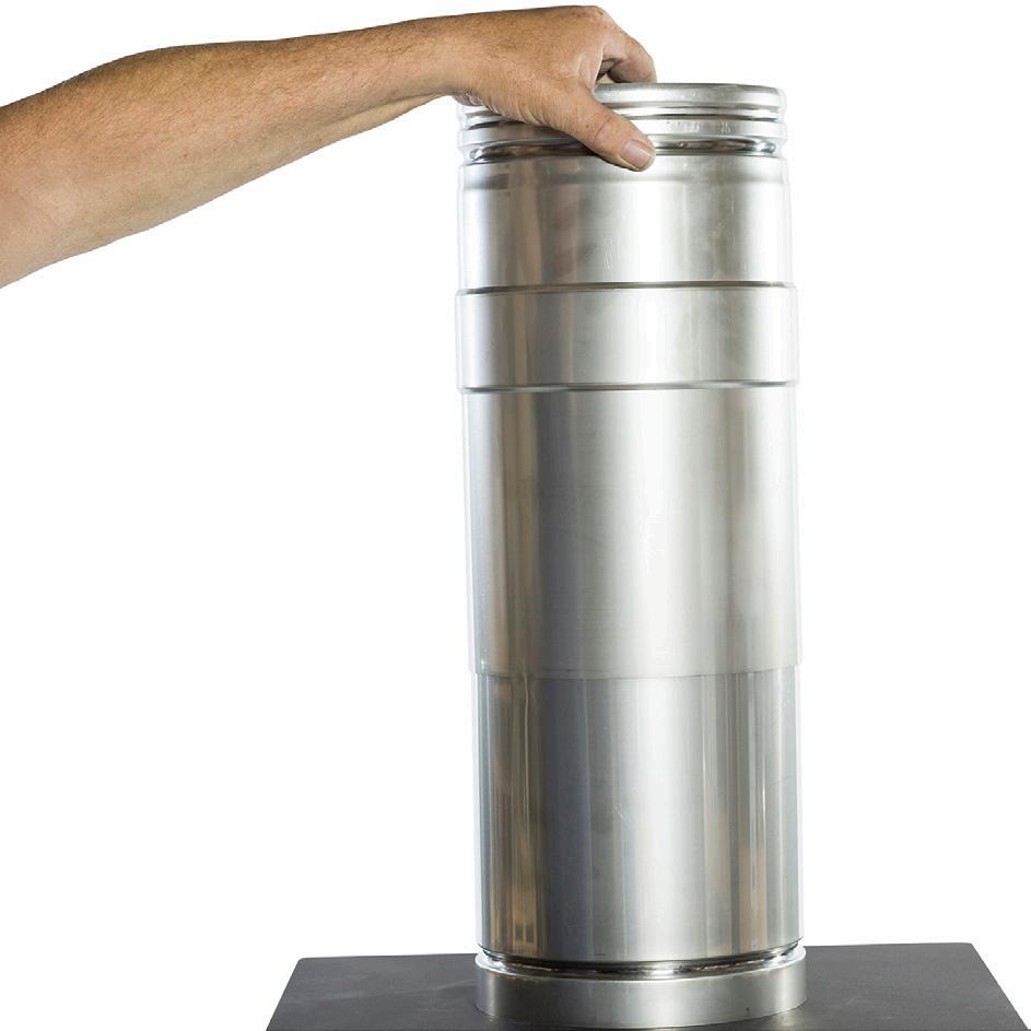
EXPLANATION 2: PIPE CLAMP (USKB)
PIPE CLAMP (USKB)
GB 22 - GB
Fit the pipes together and lock using the pipe clamp (USKB).
EXPLANATION 3: ROOF GUIDE (USDQ)
ROOF GUIDE (USDQ)
To secure the flue against wind and weather.
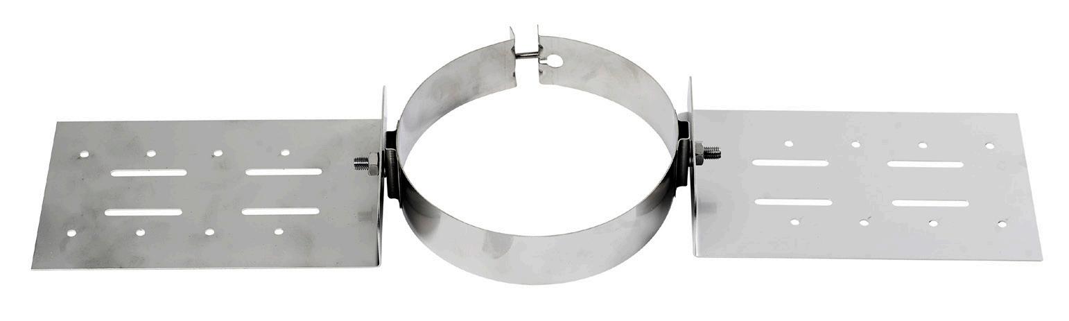
Fit around the flue.
Secure to rafters.
GB GB - 23
EXPLANATION 4: ROOF FLASHING
ROOF FLASHING
Fit the roof flashing down over the flue pipe. Push the side up towards the roof ridge up under the roof plate. Press the remaining sides down to the roof plates.
GB 24 - GB
EXPLANATION 5: STORM COLLAR (USSR)
STORM COLLAR (USSR)
Fit the storm collar down over the flue pipe, all the way down to the roof flashing and tighten.
GB GB - 25
EXPLANATION 6: EXHAUST GASES COWL AND AIR INTAKE COWL (USDVC2 10)
EXHAUST GASES COWL AND AIR INTAKE COWL (USDVC2 10)
Available in black or stainless steel.
Exhaust gases cowl and air intake cowl (USDVC2)
Fit using a pipe clamp (USKB)
GB 26 - GB
GB GB - 27
BALANCED FLUE SYSTEM THROUGH A ROOF
USD PIPE


In this section you will learn how to install a balanced flue system through a roof using USD pipe. The examples are shown with pipe dimension Ø100/150 – the pipes are also available in dimension Ø130/200 (product numbers end in 13).
USDVC2 10: AIR INTAKE AND EXHAUST
GASES COWL


See explanation 6


USSR: STORM COLLAR


See explanation 5
ROOF FLASHING
See explanation 4


NB!
Option for transition from USD pipe US pipe using adaptor (USDO) is also available.


USDQ: ROOF GUIDE


See explanation 3
USDR: ROSETTE FOR DESIGN PIPE


See explanation 2
USD 100/50/25: FLUE PIPE


See explanation 1


NB!
Option for horizontal pipework and direction changes with bends (USDB 90/45/30/20/15) also available. See page 42 for explanation.


GB 28 - GB
EXPLANATION 1: FLUE PIPE (USD 100/50/25) – “DESIGN PIPE”
FLUE PIPE (USD 100/50/25) – “DESIGN PIPE”
Available in six RAIS colours. When using USD pipe for free-standing gas fireplaces, you must always use a pipe with a measuring point. The measuring point may not be positioned in against the wall – there must enough space to take readings.
Fit the smooth end down in the fireplace.
Next, push the pipes together so that the joints are almost invisible.
OBS: A smooth pipe clamp is also available for USD pipe.
Measuring point
GB GB - 29
EXPLANATION 2: CEILING ROSETTE (USDR)
CEILING ROSETTE (USDR)
Available in different degrees (0–60 degrees) and in six RAIS colours.
Fit between the pipe and ceiling using the accompanying screws.
GB 30 - GB
EXPLANATION 3: ROOF GUIDE (USDQ)
ROOF GUIDE (USDQ)
To secure the flue against wind and weather.
Fit around the flue.
Secure to rafters.
GB GB - 31
EXPLANATION 4: ROOF FLASHING
ROOF FLASHING
Fit the roof flashing down over the flue pipe. Push the side up towards the roof ridge up under the roof plate. Press the remaining sides down to the roof plates.
GB 32 - GB
EXPLANATION 5: STORM COLLAR (USSR)
STORM COLLAR (USSR)
Fit the storm collar down over the flue pipe, all the way down to the roof flashing and tighten.
GB GB - 33
EXPLANATION 6: EXHAUST GASES COWL AND AIR INTAKE COWL (USDVC2 10)
EXHAUST GASES COWL AND AIR INTAKE COWL (USDVC2 10)
Available in black or stainless steel.
Exhaust gases cowl and air intake cowl (USDVC2)
Fit using a pipe clamp (USKB)
GB 34 - GB
GB GB - 35
BALANCED FLUE SYSTEM THROUGH A WALL


US PIPE
In this section you will learn how to install a balanced flue system through a wall using US pipe. The examples are shown with pipe dimension Ø100/150 – the pipes are also available in dimension Ø130/200 (product numbers end in 13).


USDHC1/USDHC2: WALL TERMINAL


See explanation 5

USB: BEND 90°


See explanation 4


USPP: ADJUSTABLE PIPE


See explanation 3
USKB: PIPE CLAMP

See explanation 2
US 100/50/25: FLUE PIPE


See explanation 1


GB 36 - GB
EXPLANATION 1: FLUE PIPE (US 100/50/25)
FLUE PIPE (US 100/50/25 10)
With free-standing gas fireplaces, fit a pipe with measuring points (USEM 10).
Fit the flue pipe with the end with a single groove down towards the fireplace.
GB GB - 37
PIPE CLAMP (USKB)
EXPLANATION 2: PIPE CLAMP (USKB)
Fit the pipes together and lock using the pipe clamp (USKB).
GB 38 - GB
EXPLANATION 3: ADJUSTABLE PIPE (USPP)
ADJUSTABLE PIPE (USPP)
Adjustable pipe 330–500 mm.
GB GB - 39
Pull the sliding pipe out to the desired length and lock using the accompanying pipe clamp.
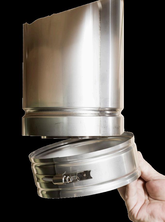
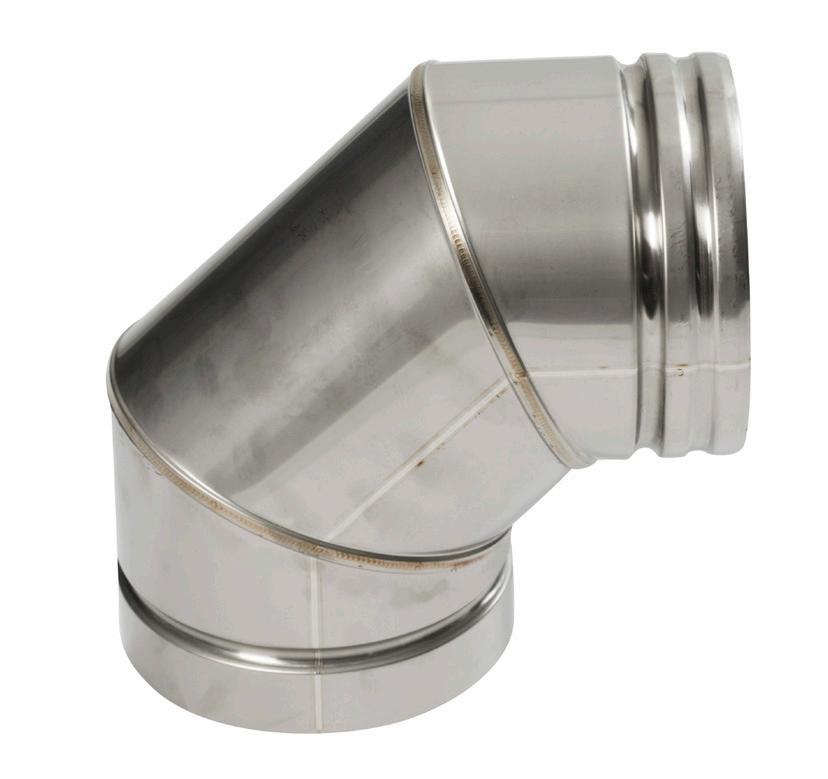
EXPLANATION 4: BEND 90° (USB 90/45/30/20/15)
BEND 90° (USB 90/45/30/20/15)
GB 40 - GB
Fit the bend using a pipe clamp.
EXPLANATION 5: WALL TERMINAL (USDHC1/USDHC2)
WALL TERMINAL (USDHC1/USDHC2)
Available in black or stainless steel.
USDHC1: for brick wall. Flange 240 x 240 mm
USDHC2: for flammable wall. Flange 300 x 300 mm
Fit outside and secure to the wall using the accompanying screws.
The wall terminal must be fitted with a 3 degree slope in the exhaust gases part.
GB GB - 41
BALANCED FLUE SYSTEM THROUGH A WALL


USD PIPE


In this section you will learn how to install a balanced flue system through a wall using USD pipe. The examples are shown with pipe dimension Ø100/150 – the pipes are also available in dimension Ø130/200 (product numbers end in 13).


USDHC1/USDHC2: WALL TERMINAL See explanation 4


NB! Option for transition from USD pipe US pipe using adaptor (USDO) is also available.


USDB: BEND 90° See explanation 3


USDPP: ADJUSTABLE PIPE See explanation 2


USD 100/50/25: FLUE PIPE WITH MEASURING POINT See explanation 1


GB 42 - GB
EXPLANATION 1: FLUE PIPE (USD 100/50/25) – “DESIGN PIPE”
FLUE PIPE (USD 100/50/25) – “DESIGN PIPE”
Available in six RAIS colours. When using USD pipe for free-standing gas fireplaces, you must always use a pipe with a measuring point. The measuring point may not be positioned in against the wall – there must be enough space to take readings.
Fit the smooth end down in the fireplace.
Next, push the pipes together so that the joints are almost invisible.
OBS: A smooth pipe clamp is also available for USD pipe.
Measuring point
GB GB - 43
EXPLANATION 2: ADJUSTABLE PIPE WITH OPTION FOR CUTTING (USDPP)
ADJUSTABLE PIPE WITH OPTION FOR CUTTING (USDPP)
Available in six RAIS colours.
Cut the pipe to the desired length and lock using the accompanying pipe clamp.
GB 44 - GB
EXPLANATION 3: BEND 90° (USDB 90/45/30/15)
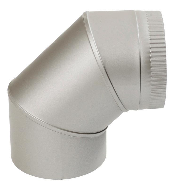
BEND 90° (USDB 90/45/30/15)
Available in six RAIS colours.
Fit the bend by pushing the pipes together.
GB GB - 45
EXPLANATION 5: WALL TERMINAL (USDHC1/USDHC2)
WALL TERMINAL (USDHC1/USDHC2)
Available in black or stainless steel.
USDHC1: for brick wall. Flange 240 x 240 mm
USDHC2: for flammable wall. Flange 300 x 300 mm
Fit outside and secure to the wall using the accompanying screws.
The wall terminal must be fitted with a 3 degree slope in the exhaust gases part.
GB 46 - GB
GB GB - 47
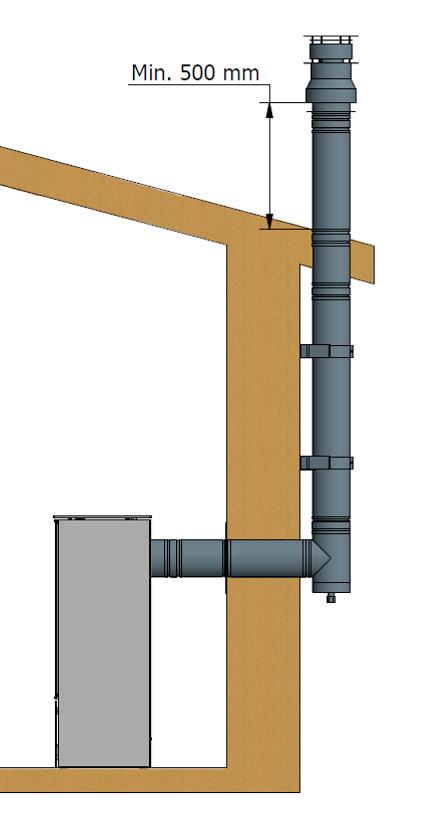
BALANCED FLUE SYSTEM UP ALONG WALL
US PIPE
In this section you will learn how to install a balanced flue system up along a wall using US pipe. The examples are shown with pipe dimension Ø100/150 – the pipes are also available in dimension Ø130/200 (product numbers end in 13).
USDVC2 10: AIR INTAKE AND EXHAUST GASES COWL
See explanation 10
US 100/50/25: FLUE PIPE
See explanation 9
USR: WALL ROSETTE
See explanation 2
USEM: FLUE PIPE WITH MEASURING POINT
See explanation 1
NB!
Option for transition from USD pipe US pipe using adaptor (USDO) is also available.
USMB 10: WALL BRACKET
See explanation 8
USKD: PIPE CLAMP
See explanation 7
UST 90 10: T PIECE
See explanation 6
USE: CONDENSATION PLUG
See explanation 5
99-USRBK 10: CONDENSATION PAN
See explanation 4
USPP: ADJUSTABLE PIPE
See explanation 3
GB 48 - GB
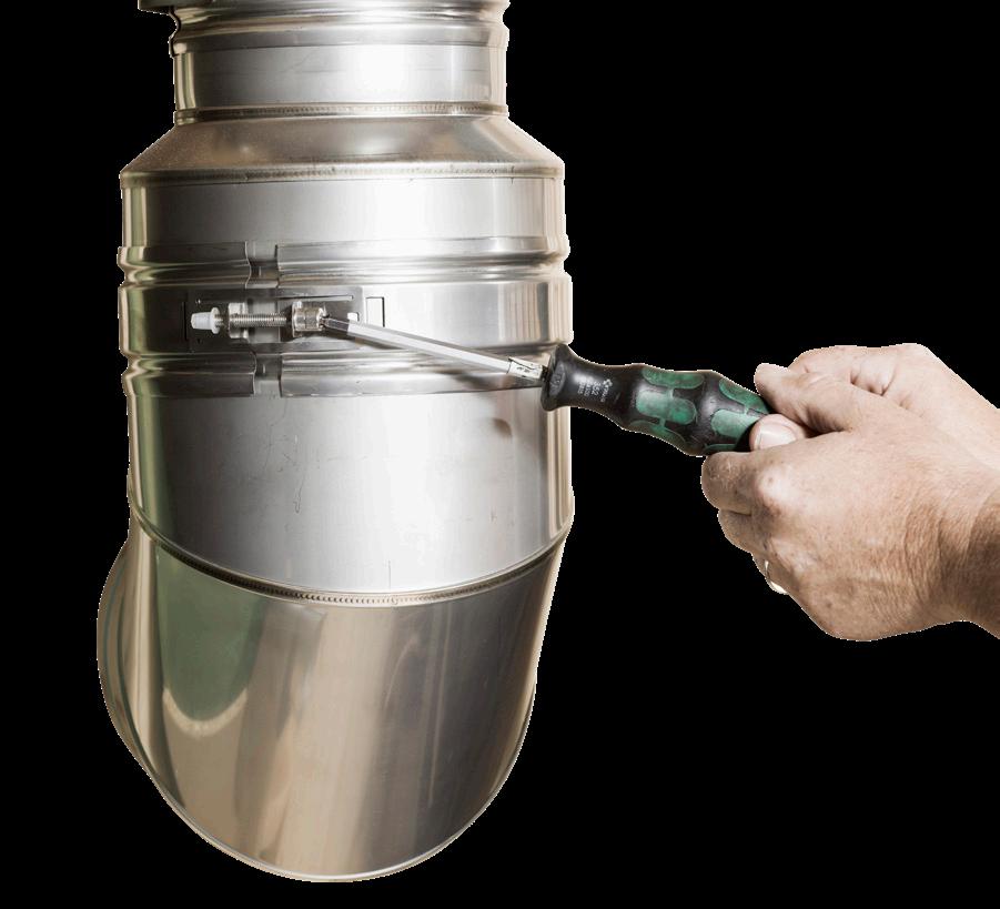
EXPLANATION 1: FLUE PIPE WITH MEASURING POINT (USEM)
FLUE PIPE WITH MEASURING POINT (USEM)
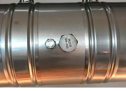
With free-standing gas fireplaces, fit a pipe with measuring points.
Bolt for outer pipe
Plug for inner pipe
GB GB - 49
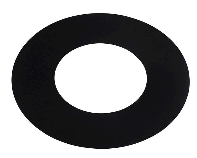
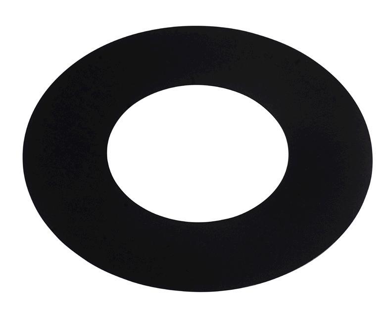
EXPLANATION 2: WALL ROSETTE (USR 10)
WALL ROSETTE (USR 10)
GB 50 - GB
Fit between the pipe and wall using the accompanying screws.
EXPLANATION 3: ADJUSTABLE PIPE (USPP)
ADJUSTABLE PIPE (USPP)
Adjustable pipe 330–500 mm.
Pull the sliding pipe out to the desired length and lock using the accompanying pipe clamp.
GB GB - 51
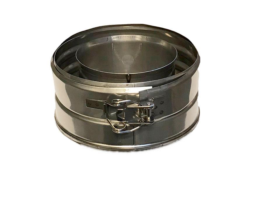
EXPLANATION 4: CONDENSATION PAN (99-USRBK 10)
CONDENSATION PAN (99-USRBK 10)
GB 52 - GB
Fit the condensation pan using a pipe clamp.
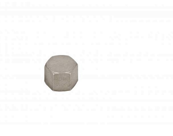
EXPLANATION 5: CONDENSATION PLUG (USE)
CONDENSATION PLUG (USE)
GB GB - 53
Fit in the extension of the condensation pan.
EXPLANATION
6: T PIECE (UST 90 10)
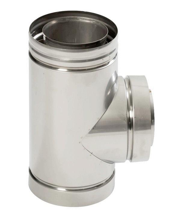
T PIECE (UST 90 10)
Connection through wall.
Fit the condensation pan here.
GB 54 - GB
EXPLANATION
7: PIPE CLAMP (USKB)
PIPE CLAMP (USKB)
GB GB - 55
Fit the pipes together and lock using the pipe clamp (USKB).
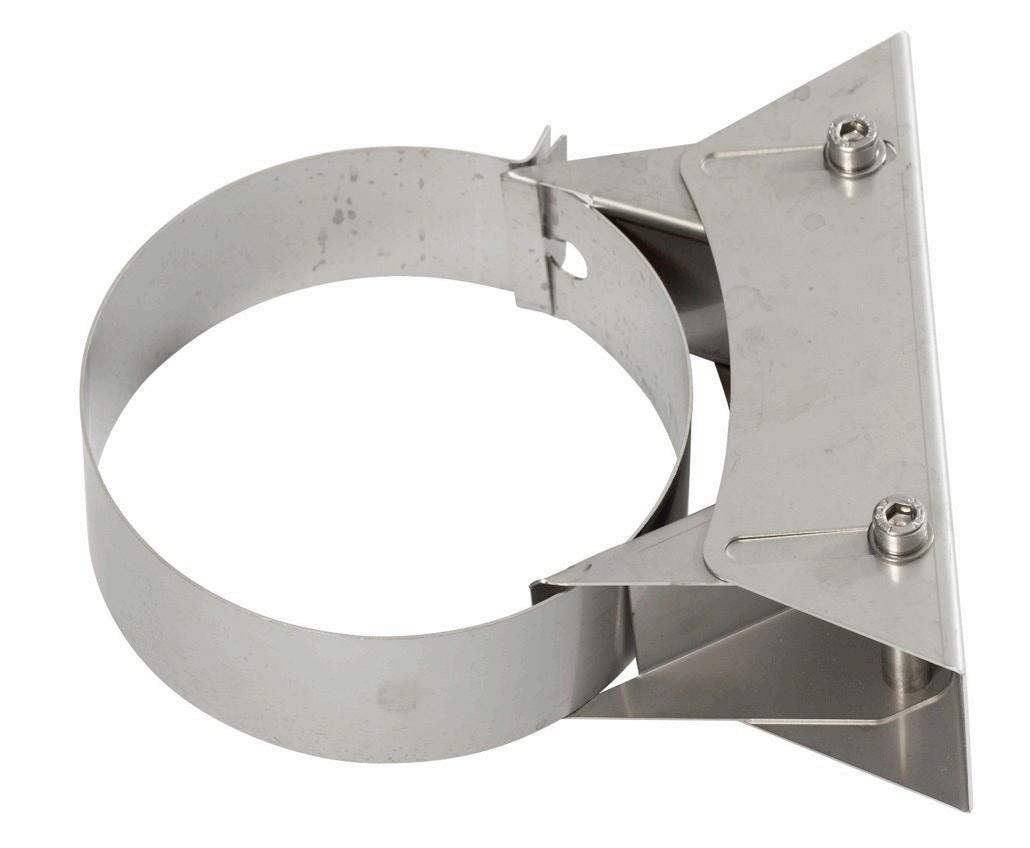
EXPLANATION 8: WALL BRACKET (USMB 10)
WALL BRACKET (USMB 10)
The bracket secures the flue pipe to the wall.
GB 56 - GB
Fit the bracket using rawl plugs and two screws.
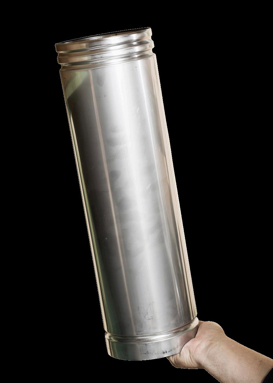
EXPLANATION 9: FLUE PIPE (US 100/50/25)
FLUE PIPE (US 100/50/25 10)
Available in lengths 1000 mm, 500 mm and 250 mm.
GB GB - 57
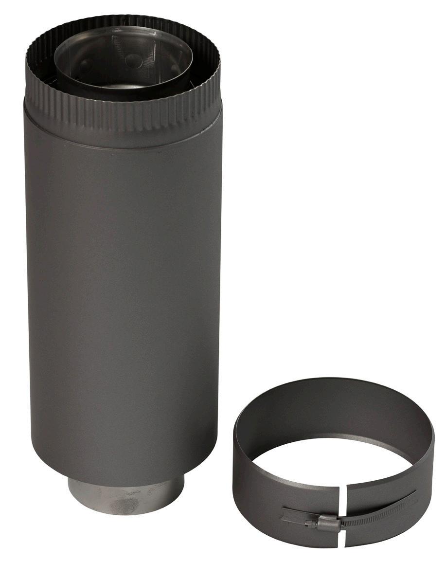
EXPLANATION 10: EXHAUST GASES COWL AND AIR INTAKE COWL (USDVC2 10)
EXHAUST GASES COWL AND AIR INTAKE COWL (USDVC2 10)
Available in black or stainless steel.
Exhaust gases cowl and air intake cowl (USDVC2)
Fit using a pipe clamp (USKB)
GB 58 - GB
GB GB - 59
BALANCED FLUE SYSTEM THROUGH A SNORKEL TERMINAL
US AND USD PIPE
In this section you will learn how to install a balanced flue system through a snorkel terminal for a top or bottom outlet. The examples are shown with pipe dimension Ø100/150 – the pipes are also available in dimension Ø130/200 (product numbers end in 13).
USDC10: SNORKEL TERMINAL
See explanation 5
US10U0052: WALL PENETRATION 600 mm
See explanation 4
USDR 10: WALL ROSETTE
See explanation 3
USDI 90 10: BEND WITH MEASURING POINT
See explanation 2
USD 100/50/25: FLUE PIPE
See explanation 1
NB!
Option for horizontal pipework and direction changes with bends (USB and USB 90/45/30/20/15) also available. See pages 36 and 42 for explanation.
TOP OUTLET REAR OUTLET GB 60 - GB
THE PRINCIPLE OF A BALANCED FLUE SYSTEM


THROUGH A SNORKEL TERMINAL
The snorkel terminal is available in two lengths: 865 mm (USDSC 10) and 1300 mm (US10U0036) in black and stainless steel.
GB GB - 61
Flue from gas fireplace in the inner pipe Wall
penetration Air intake Exhaust gases
EXPLANATION 1: FLUE PIPE (USD 100/50/25) – “DESIGN PIPE”
FLUE PIPE (USD 100/50/25) – “DESIGN PIPE”
Available in six RAIS colours.
Fit the smooth end down in the fireplace. Next, push the pipes together so that the joints are almost invisible.
OBS: A smooth pipe clamp is also available for USD pipe.
GB 62 - GB
EXPLANATION 2: BEND WITH MEASUREMENT POINT (USDI 90/45/30/15 10)
BEND WITH MEASUREMENT POINT (USDI 90/45/30/15 10)
When using US or USD pipe for free-standing gas fireplaces, you must always use a pipe with a measuring point.
Fit by pushing the pipes together.
Measuring point
GB GB - 63
EXPLANATION 3: WALL ROSETTE (USDR 10)
WALL ROSETTE (USDR 10)
Available in six RAIS colours.
Fit between the pipe and wall using the accompanying screws.
GB 64 - GB
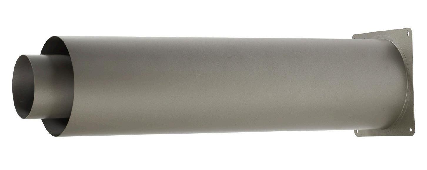
EXPLANATION 4: WALL PENETRATION (US10U0052 600 mm)
WALL PENETRATION (US10U0052 600 mm)
If required, cut off excess pipe length. Fit outside and inside using four screws.
GB GB - 65
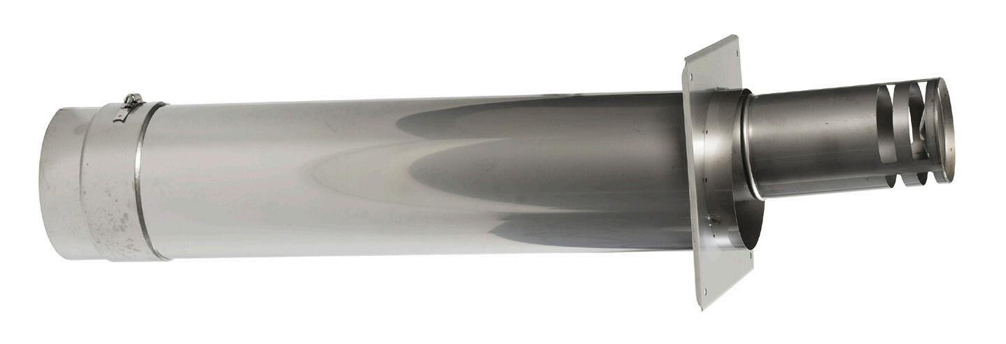
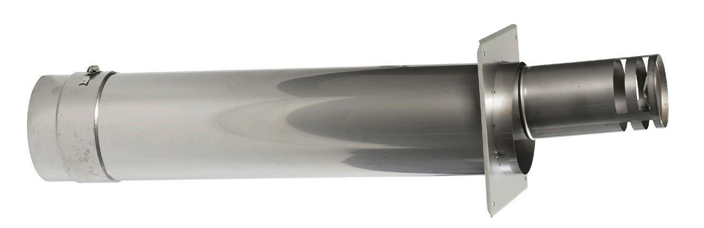
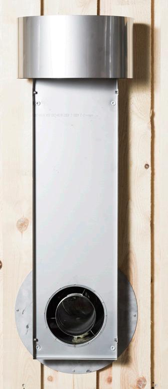
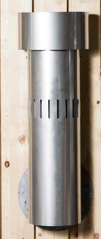
EXPLANATION 5: SNORKEL TERMINAL (USDC10)
SNORKEL TERMINAL (USDC10)
The snorkel terminal is available in two different heights: 865 mm (USDSC 10) and 1300 mm (US10U0036). The snorkel terminal can be fitted directly onto a brick wall or fitted to a flammable wall using a spacer.
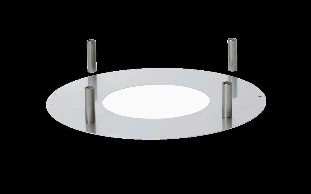
THE SNORKEL TERMINAL ON A NON-FLAMMABLE WALL.
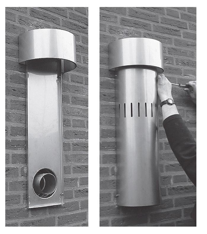 Fit the rear plate onto the wall using the four screws.
GB 66 - GB
Fit the front plate onto the rear plate using four screws.
EXPLANATION 5: SNORKEL TERMINAL (USDC10)
SNORKEL TERMINAL ON A FLAMMABLE WALL
Fit the exterior wall rosette using four screws. Install the wall penetration through the wall rosette.
Exterior wall rosette with 5 cm spacer pipe.
 Fit the rear plate onto the wall using the four screws.
Fit the front plate onto the rear plate using four screws.
Fit the rear plate onto the wall using the four screws.
Fit the front plate onto the rear plate using four screws.
GB GB - 67
The screws for fitting go through the exterior wall rosette.
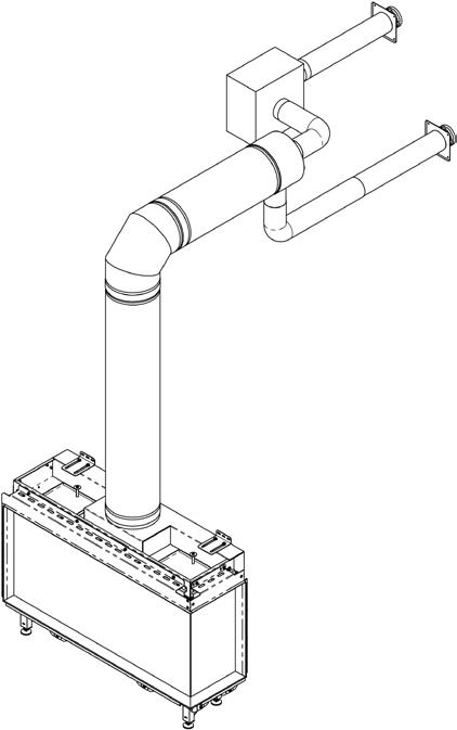
POWER FAN– FAN SOLUTION FOR LONG FLUE
POWER FAN– FAN SOLUTION FOR LONG FLUE
Solution benefits:
• More options for installation of gas fireplace.
• Provides flue options with small pipe dimension.
• Can be used for up to 30 m in length.
• Provides flue options that are otherwise not possible or unsuitable.
• Can be installed inside the building.
• Provides option for small discreet grate in the facade wall.
For more information, please contact RAIS/ATTIKA.
GB 68 - GB
POWER FAN– FAN SOLUTION FOR LONG FLUE
Return: Min. 0.2 m Max. 20 m
Power fan min. 1.5 m from fireplace.
Intake: Min. 0.2 m
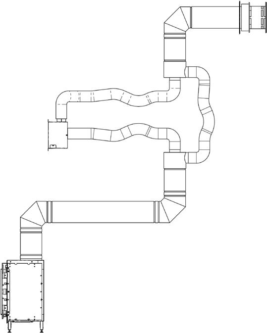
Max. 10 m
Max. 25 m for Ø200/130 mm.
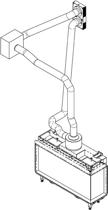
Max. 18 m for Ø150/100 mm.
Balanced flue at start and end.
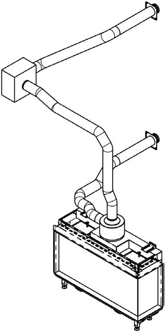 Flue with single pipe assembled in double wall terminal.
GB GB - 69
RAIS A/S Industrivej 20 9900 Frederikshavn Denmark www.rais.dk ATTIKA FEUER AG Brunnmatt 16 CH-6330 Cham Switzerland www.attika.ch 70 - DK
