2 minute read
ROBOTISM
Digital Design And Robotic Fabrication

Advertisement


Tehran, Iran | Fall 2019
Role: Instructor
Credits: Photos and diagrams were created by the workshop students and instructors. https://issuu.com/ramtinhaghnazar/docs/booklet_robotism____fall2029
ROBOTISM was a ten-day workshop held in December 2019 at the University of Tehran, focused specifically on the computational design and robotic fabrication. The workshop included 45 undergraduate and graduate architecture students who were divided into groups of 5 to 6 and practiced working with the robot. KUKA KR6 with a KRC2 controller was used in this workshop.
After teaching the KRL Syntax at the beginning of the workshop and elaborating on how to generate G- odes, the students did two series of basic exercises in their groups to learn the concept of paths in robot simulation in the first part of the workshop. For the first exercise, they were asked to draw continuous curves with specific patterns in grasshopper 3d and define the motion path of the robot and after generating the G-codes they started to light painting by using a simple LED as a tool that was placed on the robot’s head. Groups produced corresponding G-codes to make the robot follow the specified paths and print the pattern with the light. In the next exercise, each group was asked to design a structure by placing wooden pieces with specific sizes and numbers, making sure that it could maintain its stability throughout the assembly without the need for screwing or gluing.
After performing introductory tasks by the teams and getting acquainted with practical challenges like properly defining planes to prevent collision of the robot arm with its surroundings, and installation of the pneumatic gripper and air pump, students embarked on designing a pavilion on a scale of one to one. The major restriction to be considered in designs was the amount of available material, 40 square meters of 18-mm plywood. All of the proposals were assessed by the jury, and eventually, one of them opted for the final project. Modifications were also made to finalize the design.
The final design had to be prepared for the assembly process. Given the limitation of the robot’s reach to 1.6m and the conditions of the site, we decided to halve the arch and also split each half to 4 and 5 sections respectively, making a total of 9 sections. Two methods were proposed for connection of wooden pieces; utilizing a glued roller to which each wooden piece would be rubbed by the robot and placed at its position, or using a collaborative human-robotic fabrication technique in which someone would use a pneumatic nail gun to fasten objects together after being placed by the robot. Considering some practical issues and time constraints, the latter was preferred. the fabricated sections in the workshop space were transported to the campus and assembled over two hours.


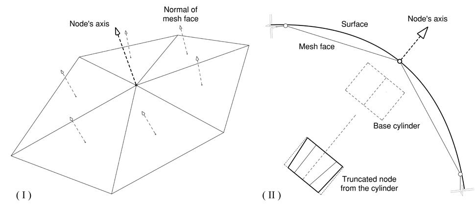
Form finding and discretization DIagrams:
- Main surface.
- Discretization.
- Dividing the installation to 9 parts considering robot size and stability of each part.

Assembly Diagrams:

The arm picks each element from the designed stand and places it in a specific position. In the grasshopper code, we checked some critical points. Firstly, each part has to be stable by itself during and at the end of the placing process. Thus, the code checks its stability in every step. Next, some of the elements, shown in red, do not have suitable support, and their pivots are out of the below elements. Therefore, we placed extra blocks without connecting them to the main ones to make the red blocks stable.


