
RILLORAZAKRYSTN 2016portfolioarchitecture-present
Our proposal for the city of Lampedusa is a space that answers to the island’s need for a green communal space that can help the locals reconnect to the island by preserving the existing conditions, value the limited resources and work towards making Lampedusa into a self-sustaining island. To do this, we propose the Oasis. This new urban green space protected by a canopy is a place for environmental education in which cultural, recreational and gastronomical opportunities as well as providing indoor and outdoor thermal comfort are provided for the locals and tourists.

Oasis Lampedusa, Italy Technische Universität München, Summer 2018 Building Technology and Climate Responsive Design Professor Thomas Auer, Prof. Dipl.-Ing
In collaboration with Doron Revach and Anna Volinia

C T Y F A B C D F 1 0 1 23 5 6 7 4 8 9 10Proposed Green Forum Liceo - Istituto Onnicomprensivo L. Piradello Scuola Materna Municipale (Pre-Elementary) Elementary and Middle School Scuola Materna (Pre-elementary school) Marina Diving Lampedusa The Green Diving Moby Diving Center Lampedusa 0 1 2 3 4 5 6 7 Educational Hot-Spots BAC SITE: unused green area PU B L C G R EE N PU B L C S PAC COMMERCIALRESIDENTIALES TOURISM EDUCATION ProgramsPiaPiaPMUNICIPALITYSPORTOFFICESVIAROMAortoDiLampedusazzaCom.BrignonezaG.Garibald Near the Site fromthesuburb fromtheharbor Scale: 1:200 0 1 2 104 Section A-A

PROMOTION:programEMPLOYEES: summer stage for students of the professionalPROVISION:school gray water and organic waste for the green areas two pavilions for public environmental and sustainable tourism educationspaceWORKSHOPS:LECTURES:forschool, innovative methods of communication and education RECREATIONAL CENTER: after school space for children PUBLIC AND PRIVATE INDOOR EVENTS: rentable space, temporary exhibitions
FASTWOODYPERENNIALPIONEERSGROWINGTREESLONGTERM TREES

small eventsperformancesforchildren PARK MOSSES GRASSES GRASSES
meetingPLAZApointlarge gathering greenspaceBOTANICAL PATH discovering the flora typical of the GREENTRADITIONALSUSTAINABLEislandKITCHENTERRACESrelaxingareashadedgreenspacewithseatingMODULARCANOPY(FUTUREGREENROOF)solarcontrolfreeconfiguration
SUBSTRATUM: the C horizon is the parent material from which the upper soil layers developed. It consists primarily of large BEDROCK: the parent material from which the upper soil layers developed consists of large rocks.
SUMMER TIME noonnoon eveningevening SCHOOL TIME SCHOOL TIME eveningnoonafter centerrecreationalschool summer stage for students indoor cinema city privateassembliesmeetings KITCHEN eveningnoon SCHOOL TIME KITCHENWORKERSCHILDRENTEENSRETIREESTOURISTS

Hotel O’Scia TOPSOIL: it is only 5-10 inches thick and consists of organic matter and minerals. This is the soil layer where plants and organisms primarily live.
AMPHITHEATERCHILDRENTEENSWORKERSRETIREESTOURISTS
FLEXIBLE PAVILIONS GREEN


STAGEWALLS
workshopslectures after centerrecreationalschool summer stage for students indoor cinema city privateassembliesmeetings artistic and temporaryperformancesmusicexhibitions KITCHEN SUMMER TIME eveningnoon SUMMER TIMESCHOOL TIME SUMMER TIMESCHOOL TIME SCHOOL TIME noonnoon eveningevening noonnoon eveningevening eveningnoon WORKERSCHILDRENTEENSRETIREESTOURISTS AMPHITHEATERCHILDRENTEENSWORKERSRETIREESTOURISTSFLEXIBLEWORKERSCHILDRENPAVILIONTEENSRETIREESTOURISTS outdoor lectures outdoor lectures public outdoorperformanceslecturescinema outdoorperformancescinema MINI THEATER CHILDREN TEENS WORKERS RETIREES TOURISTS meetingplaygroundpointevents for children small performances workshopslectures after centerrecreationalschool summer stage for students indoor cinema city privateassembliesmeetings artistic and temporaryperformancesmusicexhibitions KITCHEN Scale: 1:2.000N 0 5 10 5020 Stakeholders of the Oasis Site Plan Floor Plan A A
SUBSOIL: mostly made of clay, iron minerals as well as organic matter, which has been washed down to this horizon by rainwater.
PHASE:TRANSITIONALareagreenunusedCONDITION:EXISTINGSOILREMEDIATIONPROCESSCONNECTIONSANDGREENQUALITYEDUCATIONTHERMALCOMFORT


SUMMER TIME noonnoon eveningevening SCHOOL TIME SUMMER TIMESCHOOL TIME SCHOOL TIME noonnoon eveningevening eveningnoon WORKERSCHILDRENTEENSRETIREESTOURISTS
thermal benefits visual atmosphere integration of solar panels structure for climbing plants nutrition education
outdoor lectures public outdoorperformanceslecturescinema
FLEXIBLEWORKERSCHILDRENPAVILIONTEENSRETIREESTOURISTS
WORKERSCHILDRENTEENSRETIREESTOURISTS FLEXIBLEWORKERSCHILDRENPAVILIONTEENSRETIREESTOURISTSworkshopslectures

FuturePresent Thermal Comfort Strategies


summer sun radiation blocked by the fixed canopy and absorbed by the PV panels DOUBLE ROOF CROSS VENTILATION CROSS autumn(indoorVENTILATIONcomfort)andspringsunradiation blocked by the closed canopy winter sun radiation passes through the open canopy CONTROLLED SHADING WITH THE OPERABLE CANOPY (outdoor comfort) FASTER COOL DOWN IN THE EVENING EVAPOTRANSPIRATION(climbingplants) WINDS FROM THE NW FORVENTILATIONNATURAL 27° 76° 52° The site is ex posed to plenty of solar ingsummerradiationintenseprotectedTheopen.theradiationthetheInyear.throughoutradiationthethewinter,sitereceivesmostsolarwhencanopyissiteisfromsolarinthebyclosthecanopy. Site Radiation Analysis Annual Summer Winter CanopyClosedCanopyOpenSiteExisting 1600< 1440 1280 1120 960 800 640 480 320 160 <0 kWh/m2 Fixed Operable Green Canopy Module Variations
The green canopy flourishes and becomes more dense over time, providing more shade. The canvas on the canopy is replaced with a structure for green to grow. The fixed modules stay as they are.


The Museo Modulo is the headquarters for the Chicago International Architecture Biennale 2017 located in the neighborhood of the West Loop in Chicago. Our proposal makes architecture as a form of public art and a center for cultural production. The Museo Modulo was derived from our speculative architecture studies in Metabolism. Our proposal is able to expand by creating modules that attach to the exisitng structure by 3D printers, robots and drones that work within the building. The large atrium allows for interlocking of different spaces and for the drones to fly up to the roof.

In collaboration with Max Zorn
Museo Modulo Chicago, Illinois University of Illinois in Urbana-Champaign, Fall 2017 Architecture and Urban Design Professor Thérèse Tierney, Ph.D
SPECULATIVE ARCHITECTURE: MUSEUM OF THE FUTURE collaboration and learning. In addition to the exhibition modules, there are also modules for cafes, lounges, libraries, etc. These modules are able to shift and rearrange itself based on a profile that each visitor submits. There fore, the museum shapes itself to the needs of the visitor. The artifacts in these modules represent different moments in time, therefore these artifacts should remain to be exhibited, to never be forgotten. We should not forget our history, it plays a big part in shaping our present and our future.
B1*G0203040506070809101112131415rooftop bar rooftop restaurant rooftop architecturearchitecturerestaurantlibrarylibrarygallery+daycaregallery+daycare officesoffices mechanicalpermanenthanginghangingauditoriumauditoriumworkshop+atrium+gallery+VRgallerygallery+gallerystorage+lobbyglassboxbar+lobbyrooms
The museum of the future should continue to grow and expand instead of being constrained by a form. The concept of Metabolism informs the structure of the mu seum. Modules that house different exhibits are created in the base of the museum, flown out to different art ists, scientists, or historians using deployable balloons, and brought back to the museum to be plugged in. This allows for the museum to continue to grow instead of removing exhibits to be replaced with something new. This also creates an opportunity to transport exhibits to other locations around the world. The museum not only exhibits artifacts, but also be comes a space for

Lobby view: hints of each space is visible as user ascends the main stair in the lobby.


Form studies with interlocking modules.


Final model: cast rockite and wood.


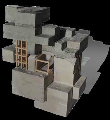
Atrium View: robotic arms in the workshop build parts for pavilions to be transported and constructed by flying drones to the rooftop.
Form progression from interlocking modules to final form.
a b c d gef h i j k

k.j.i.h.g.f.e.d.c.b.a.
150/50 mm steel RHS roof insulationprotectivestoneconstruction:tileslayer;seal reinforced concrete floor deck 310-450 mm steek hollow-floor construction reinforced concrete slab cinema wall construction: double polycarbonate panels floor construction: 30 mm flooring 140 mm composite floor slab with thermal grid 310-450 mm steel hollow-floor construction reinforced concrete slab auditorium wall construction: double glazing, 0.5 spacing fabric curtain 6mm laminated safety glass gallery wall construction: double glazing, 0.5 spacing 6mm laminated safety glass 6 mm laminated safety glass aluminumgrate siding reinforcedinsulation concrete gallery wall construction: concrete panels with perforations double glazing, 0.5 spacing basement wall construction: vapor reinforcedinsulationbarrierconcrete basement floor construction: stone reinforcedtiles concrete vaporinsulationbarrier
GROUND LEVEL PLAN BASEMENT 1 PLAN BASEMENT 2 PLAN
Mountain Film Institute Luster, Norway

AAB B09.09.09.09.09.09. 10. 05. 06.07. 07. 02.02.02. 08.02.08.08. 01. 04.04. 45’ 42’ 42’ 61’ 167’ 15. 16. 08.11.08.08. 06. 04.04. 12. 14. 13. 45’ 57’ 42’ 34’ 41’ 58’ 54’ 14’ 16. 08. 04.04. 18. 17. 16. 17. 17.17.17.19. 85’ 45’ 36’ 58’
Dedicated to support the art of mountain films, my pro posal aims to provide spaces for film viewing, exhibi tion and shelter while providing views to the Hurringane peaks. The harsh climate of the mountains in Norway and the 2030 Challenge with 60% target was considered in the design and technologies of the film institute.
University of Illinois at Urbana-Champaign, Spring 2017 Technology & Performance Professor Vidar Lerum, Ph.D

RELAX012 618 WORK012 618 OBSERVE012 618 WATCH012 618 OPERATING HOURS SCIENTISTSARTISTSHIKERSWORKERS
UNOBSTRUCTED VIEW panoramic view of the Hurrungane peaks on the terrace by the main enterance. FRAMED VIEW Experience the Hurrungane peaks with the exhibit. NO VIEW Focus on the mountain films.
04.03.02.01.
The different activities that oc cur in the institute was broken down to four categories: relax, work, observe and watch. The daily occupancies of spaces that fall under each category were studied so that the placement of the different program areas correspond to the time of day that activity is being done.

DIMINISHING VIEW OF THE HURRUNGANE PEAKS
rectangle form with the long side towards the south to maximize solar gain and views to the extrudeHurringane.from the south wall for program for views.carvea path through the institute to provide for a tunnel view of the Hurrin gane from the approach. add the glass column as the entrance and acts as a beacon in the evening hours.
As the user decends through the Institute, the view of the Hurringane peaks dimin ishes based on the activity on each level. Approach from the main road

DAILY OCCUPANCY

Solar
& SOLAR
PV
PV
HEATINGMECHANICALMODE
ELECTRICITY CONCEPT
PV
FACADE ENERGYdouble skin electronicallyfacade:operated PV panels air cavity, 36 in anodized aluminum rainscreen panel rainscreen structure air gap, 2 in OSB, 1/2 in mineral fibre insulation, 16 in air/vapor barrier precast concrete wall panel, 16 in gypsum board, 5/8 in occupiable roof structure: stone tiles, 1 in strain & drain vapor barrier OSB, 1/2 in mineral fibre insulation, 16 in concrete hollow core, 16 in raised floor: stone tiles, 1 in raised floor support floor concretediffuserhollow core, 12 in dropped ceiling: knife edge dropped ceiling light doubleairsinglealuminumboxreturnreflectorfixtureairductwindowsystem:frameglassgap,11inglass,low-e,1/2in.spacewithargon gas thermally broken frame concrete floor structure: polyethelyne house wrap mineral fibre insulation, 20 in concrete slab, 22 in concrete footing, 24 in CIRCULATION CONCEPT / a: thermal solar panels, 1,030 sqft. b: ventilation & heat recovery c: water d: heat store e: operable windows f: naturally ventilated a: water collection b: disinfection c: heat store d: micro waste water filtration e: showers f: water saving fixtures g: grey water reuse a: photovoltaics, 15,400 sqft b: heating c: excess power sold to grid Energy on Surface (kWh/yr) Solar Energy Generated (15%) (kWh/yr) Panels Closed (95%/yr) 572,200 86,000 81,700 Panels (5%/yr) 705,000 105,900 5,300 on Roof 447,500 67,100 67,100
a b c d e a g b c d e a b c 0’ .5’ 2.5’ 5’ a b c d e 10 10050 UNFOLDEDkWh/sqft
POWER
d.b.a.c.e.f. WATER
BIPV 50,400 7,600 161,7007,600 161,100 kWh/yr Target (kBTU/sqft-yr)60% Floor(sqft.)Area Required(kBTU/yr)energy Enetertainment 16.8 18046 303,173 Lodging 28.8 2,569 73,987 Cafeteria 82.8 1,433 118,652 Library 36.8 818 525,00030,102 154,000 kWh/yr 2030 CHALLENGE, 60% TARGET HEATING / VENTILATION CONCEPT COOLINGMECHANICALMODE: PV panels open to allow fresh air into building. PV panels are rotated to an angle that maximizes the amount of solar energy captured throughout the summer months. Panels also act as shading devices.
Outer skin is closed but the air in the corridor airradiation.heatedbecomesbysolarThewarmisthencirculatedinsidethebuilding.Thecorridoralsoactsasaninsulatingbuffer. Summer Sun Winter Sun FACADE DESIGN: Inspired by the silhouette of the mountains
Deployable Structures: Fall 2016, University of Illinois at Urbana-Champaign


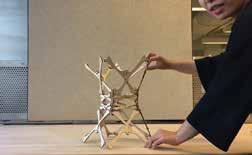


In collaboration with Miya Teng, Ivana Rakshit, Yuqiao Zhang and Edward Shen. We studied deployable structures in order to explore its potential in architecture. 4.

The Lake Winnipeg’s Writer’s Studio, situated on the south of the beautiful lake, is a completely passive and adaptive structure. Winnipeg’s climate demands high heating loads, so to answer to this requirement, we proposed a building envelope system that consists of double glass vacuum system, an air buffer zone and a wall of water for thermal mass. Oriented with a view of the lake, visiting writers can draw inspiration from nature. 1.
Other Projects


Case Study - Cadix by Sergison Bates Architects: Summer 2018, Technische Universität München In collaboration with Maja Paulsen Skjerdingstad and Pauline Vermeulen. We studied how repetition implies the replication of an element, over and over, while experiencing intensity in this sameness, brought about by the repetition of pattern by modeling case study buildings in 1:100 scale. 3. angle of each angulated member: α = 360°/9 = 40° Ψ = φ = 180° - α Ψ = φ = 180° - 40° = 140° length of each angulated member: sin(α/2) = (b/2)/l sin(40°/2) = (b/2)/9” b < 6.16”
Found Moments - Light & Atmosphere Studies: Summer 2018, Technische Universität München In collaboration with Maja Paulsen Skjerdingstad and Pauline Vermeulen. In speculation of the possible atmospheric character of the shared spaces of a very large collective building, we were asked to find an existing place that expresses material atmosphere. Then recreated the lighting levels and atmosphere we observed in the photograph (left) by modeling in 1:10 scale and photographing the model from the exact angle (right). 2.
Entirely Passive Building in Winnipeg, Canada: Summer 2018, Technische Universität München


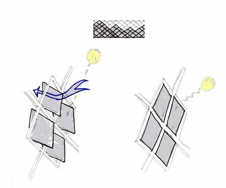
This screen blocks solar radiation but isn’t allowing enough daylight into the spaces. This screen is successful in blocking solar radiation and allows sufficient daylight into the space.
Daylight in this room is not DaylightisDaylightsufficient.inthisroomsufficient.inthisroom is sufficient. Bringing the overexposed wall back will still allow for sufficient daylight (while reducing the amount of solar radiation on the facade) like the room directly north. Daylight in this room can be improved. South Facade Solar WinterRadiationSolstice North Facade Solar SummerRadiationSolstice <0.000.501.001.502.002.503.00<lux)300>Time(%DA>3000lux>5%1000 kWh/m Fall/Spring Equinox South Facade NoAngle:Cut-off22°VerticalShadingShadingCut-offAngle:33°Cut-offAngle:45° Fall/Spring Equinox West Facade Fall/Spring Equinox East Facade Summer Solstice North Facade <1.01.52.02.53.03.54.04.55.0< kWh/m2 zoneDesired Daylight AvailabilityDaylight Autonomy UDI OverlitUDI Underlit 0 100 DA (% Time > 300 lux) >5% >3000lux 0 100 UDI Underlit (% Time > 300 lux) 0 100 UDI Overlit (% Time > 300 lux)
Solar SummerRadiationSolstice <0.000.501.001.502.002.503.00<lux)300>Time(%DA>3000lux>5%1000 kWh/m2


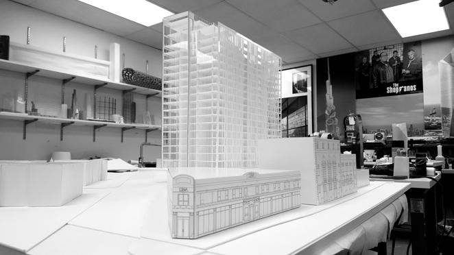
During my time at SOM Chicago, I was fortunate enough to join a team working on a mixed use development in the heart of Chicago’s Lincoln Park neighborhood. I had the opportunity to work on the exterior facade design and model (above).
1.
Daylight
DaylightisDaylightsufficient.inthisroomsufficient.inthisroom
South
This wall being pushed out resulted in higher exposure to solar radiation during the winter months.
Solar
Daylight in this room is not Daylightsufficient.intheseroomscanbeimproved.
Daylight in this room is not is sufficient. Bringing the overexposed wall back will still allow for sufficient daylight (while reducing the amount of solar radiation on the facade) like the room directly north. Daylight in this room can be improved. Facade Facade

Transsolar KlimaEngineering Intern, New York, NY
Skidmore, Owings & Merrill Architectural Designer, Chicago, IL

© Transsolar newyork@transsolar.comInc. 220 E 23rd St. Suite 403 New York, NY 10010 KP KR +1 212 219 2255 Centre of Excellence in Biomedical Engineering Kigali, Rwanda Solar Radiation & Daylight Analysis 14 December 2018 4 Availability and Radiation Availability and Solar Radiation

With Transsolar, was responsible for simulating daylight (upper right) and solar radiation (left & above) conditions with respect to the project location and context. By simulating daylight conditions, was able to determine if the percentage of glazing or the shading devices are optimized for best indoor daylight quality. The solar radiation studies helped determine if the existing shading devices is appropriate for its respective facades. It can also help make informed decisions in determining appropriate building massing and locating possible locations for passive building systems. 2.

Daylight
This screen blocks solar radiation but isn’t allowing enough daylight into the spaces. This screen is successful in blocking solar radiation and allows sufficient daylight into the space.

Daylight in this room is not Daylightsufficient.intheseroomscanbeimproved.
© Transsolar newyork@transsolar.comInc. Availability Availability
220 E 23rd St. Suite 403 New York, NY 10010 KP KR +1 212 219 2255 Centre of Excellence in Biomedical Engineering Kigali, Rwanda Solar Radiation & Daylight Analysis 14 December 2018 4 Daylight

Professional Experience
This wall being pushed out resulted in higher exposure to solar radiation during the winter months.
and Solar Radiation Daylight

and Solar Radiation
Solar WinterRadiationSolstice North
Workplace Interiors Office in New York, NY. Developed(Completed).architectural plans, construction documents, presentation materials. Modeled, documented and detailed architectural stair (shown below). Lead the design, layout, finish selections, details and drawings of restrooms. Worked directly with reps to select brand new, highend products and finishes. Owned keynotes of all recorded finish and materials, kept keynotes organized for the use of spec writer.


A-654 A-654A-655 TOSCHEDULEDGUARD,DETAILSREFERENLARGEDSCHEDULEDENLARGEDSCHEDULEDGLASSCEILINGSCHEDULEDSCHEDULEDTOSCHEDULEDPLATFORM/PLANTERWOODPANELENCASECONVECTORGYPCEILINGWOOD/FABRICSMOKEBAFFLECEILING,SEERCPCEILING,SEERCPTOSTAIRPLANANDFORTREADSANDTYP.WOODPANELCOVERCONVECTOR MS3MS306 WP 05 MS3MS3 06 WP 05 MS3 06 WP 05 05 MMSMS3MS2MS3MS3MS3 A-656A-656A-656SIM ETCHEDBACKPAINTEDGLASS A-656 SIM ALIGNALIGN ALIGN ALIGN ALIGN ALIGN ALIGN ALIGNMENT WITH SMOKE BAFFLE WOOD FINISH SEAMS TO ALIGN THROUGHOUT A-654A-655 SCHEDULED CEILING, SEE ENLARGED RCP. REFER TO STAIR PLAN AND DETAILS FOR TREADS AND GUARD, SCHEDULEDTYP..CEILING, SEE ENLARGED RCP. WOOD STAIR UP TO 2ND TREAD SEE DETAILS 05 MS3 21 05 MS3 23 05 MS3 24 05 MS3 25 05 MS3 22 05 MMS MMSWP05WP0505 MS3 22 05 MS3 21 05 MS3 21 05 MS3 LIGHTINGSCHEDULED25FIXTURE A-656 A-656 NOTE: PROVIDE WATERPROOFING INSIDE AT BOTTOM AND SIDES OF PLANTER A-657A-657 ALIGNALIGN ALIGN ALIGN ALIGN ALIGNALIGN ALIGNALIGNALIGNALIGN 43RD FLOOR (CONSTRUCTION) 44TH FLOOR (MARKETING) 46TH FLOOR (CONSTRUCTION) 47RD FLOOR (MARKETING) 47TH FLOOR (CONSTRUTION) 48TH FLOOR (MARKETING) CA SHEET NUMBERTITLE JobDrawnCheckedApprovedNumber ISSUEPROJECTKEYPLANCHART.00C2010AMBM6BCPWBCCNRA A 655 46TH 48TH FLOOR STAIR SECTIONS 035792.000CheckerAuthorApprover BESSEMER TRUST Copyright © 2020 Perkins&Will 630 FIFTH AVENUE, NEW YORK, NY 10111 1271 AVENUE OF THE AMERICAS, NEW YORK,10020NY BESSEMER TRUST 3/8" 1'-0"1 46TH -48TH FL STAIR -WEST SECTION 3/8" 1'-0"2 46TH -48TH FL STAIR -SOUTH SECTION. MARK ISSUE DATE DESIGN DEVELOPMENT 09.05.2019 50% CONSTRUCTION DOCUMENTS11.07.2019 ISSUED FOR LANDLORD REVIEW PRE-PURCHASE 02.14.2020 ISSUED FOR BID 03.23.2020 ADDENDUM #1 04.17.2020 ISSUED FOR CONSTRUCTION03.23.2020 FDFD FD FD FEC 09 TL 05A 09 TL BATHROOMPRIVATE05C47002 06 WP 01 06 WB 01 09 WF LOUNGE0147030 09 DCS 02 09 WB 04 09 CPT CAPTAIN04AOFFICE47001 SEESEEHALLWAYELEV.ELEV.09TL1847016 09 PT 01 09 RB 01 09 STORAGELF47035 RM.# 09 PT 01 09 RB 01 09 SDT 01 47027IDF 09 TL 14 09 RE KITCHEN0247007 09 TL 14 09 RE 02 WALK COOLERIN4700909 DCS 02 09 WB 04 09 CPT 04A PHONE47037ROOM RM.# ELEVATORLOBBYSEEELEV.SEEELEV.09TL2147000 09 DCS 02 06 WB 04 TL HALLWAY1847020 STAIR47029 B C D E F G H K M N SEE ELEV. SEE ELEV. 09 CPT 05 CONF47021ROOM SEE ELEV. SEE ELEV. 09 CPT 05A CONF47023ROOM SEE ELEV. SEE ELEV. 09 CPT 05A CONF47022ROOM09 WC 03 06 WB 05 09 CPT 04A CONF47025ROOM 09 WC 03 06 WB 05 09 CPT LOUNGE0647026SEE ELEV. SEE ELEV. 09 CPT 04 CONF47028ROOM CONF ROOM 06 WP 02 06 WB 02 09 WF 4700303 SEE ELEV. SEE ELEV. 09 CPT 04 CONF47004ROOM SEE ELEV. SEE ELEV. 09 CPT 04 CONF47006ROOM CONF ROOM 09 WC 03 06 WB 05 09 CPT 4701104A 09 WC 03 06 WB 05 09 CPT LOUNGE0647010SEESEEHALLWAYELEV.ELEV.09TL2147005 RM.# SEE ELEV. SEE ELEV. 09 CPT 05 CONF47015ROOM SEE ELEV. SEE ELEV. 09 CPT 05A CONF47013ROOM SEE ELEV. SEE ELEV. 09 CPT 05A CONF47014ROOM 09 TL 05A 09 TL WOMENS0447034 09 TL 05A 09 TL MENS0447033 09-CPT-04 09-CPT-05 09-CPT-03 09-CPT-05 09-CPT-03 09-CPT-05 09-CPT-03 09-CPT-0409-CPT-04 09-CPT-09 A-605C A-60311 SIM 09 DCS 06 WB 04 09 TL 47031ACOAT21 RM.# HARDMECHANICALFLOOR47000A 09-CPT-04A 09-CPT-04A 09-CPT-05A RM.# 09 PT 01 09 RB 09 LF VESTIBULE0147036 09-CPT-04B 09-CPT-04B 09-CPT-04A09-CPT-04B 09-CPT-05B09-CPT-05A 09-CPT-05B09-CPT-05A09-CPT-05B09-CPT-05A09-CPT-05B09-CPT-05B09-CPT-05A RM.# SEE ELEV. SEE ELEV. 09 CPT 05 CONF47017ROOM RM.# 09 DCS 02 06 WB 04 09 TL HALLWAY2147032 09 DCS 02 06 WB 09 TL HALLWAY214702909 PT 01 09 RB 09 TL 47032A24JC 09-TL-21 06-WP-01 09-CPT-05B09-CPT-05A09-CPT-05B09-CPT-05A09-CPT-04B09-CPT-04A 09-CPT-04B09-CPT-04A FN1 FN6 FN6FN6 A-619 43RD FLOOR (CONSTRUCTION) 44TH FLOOR (MARKETING) 46TH FLOOR (CONSTRUCTION) 47RD FLOOR (MARKETING) 47TH FLOOR (CONSTRUTION) 48TH FLOOR (MARKETING)DC CONSULTANTSPROJECT FOODSTRUCTURALAUDIOVISUALOWNERSERVICECONTRACTOR PERKINS & WILL ARCHITECTS, P.C. SECURITY BESSEMER TRUST 1271 AVENUE OF THE AMERICAS, NEW YORK,10020NYSILMANSHEN MILSOM WILKE 417 FIFTH AVENUE NEW YORK, NY 10016 32 OLD SLIP, 10TH FLOOR, NEW YORK, NY 10005 ROBERT DERECTOR ASSOCIATES 19 WEST 44TH STREET NEW YORK, NY 10036 ROBERT DERECTOR TELECOM 19 WEST 44TH STREET NEW YORK, NY 10036 MILROSE CONSULTANTS, INC. 498 SEVENTH AVENUE NEW YORK, NY 10018 CODE SHEN MILSOM WILKE 417 FIFTH AVENUE NEW YORK, NY 10016 BESSEMER TRUST 630 FIFTH AVENUE, NEW YORK, NY 10111 JACOBS DOLAND BEER 192 LEXINGTON AV, SUITE 804 NEW YORK, NY 10016 JT MAGEN 44W 28TH STREET, 11TH FLOOR NEW YORK, NY 10001 ROBERT DERECTOR TELECOM 19 WEST 44TH STREET NEW YORK, NY 10036 215 Park Avenue4thSouthFloor New York, NY 212.251.7111212.251.700010003 www.perkinswill.com 1/8" 1'-0"1 47TH FLOOR FINISH PLAN


OVER TREADED PLYWOOD SCHED. OFFICE FRONT SYSTEM METAL EDGE TRIM SCHED.FIXTURELIGHT MIN6"ALIGN C-JOISTS RIM JOISTC-JOISTSTRACKTAB16"O.CWITHTREATED 3/4" T+GSTAIRSUBFLOORLANDNG SCHED. OFFICESYSTEMFRONT EXISTING CONCRETE RAMP 2X4 COLD FORM METAL METAL 3/4"JOISTSTUDTABHARDWOOD FLOOR 3/4" PLYWOOD SUBSTRATE JOIST RIM TACK COLD FORM METAL CHANNEL, MOUNT TO FLOOR HANDRAILMETALCAPGLASSGUARDRAIL2X4COLDFORMMETALSTRINGERANGLESUPPORT 121M0 1/2" 1'-0"1 HELIX POD CROSS SECTION 1/2" 1'-0"2 HELIX POD LONGITUDINAL 1/2" 1'-0"3 HELIX POD BRIM HEAD DETAIL 1/2" 1'-0"4 HELIX POD WALL DETAIL 1/2" 1'-0"5 OFFICE FRONT FLOOR DETAIL 1 1/2" 1'-0"6 HELIX POD STAIR DETAIL


A-506.00 DOAS24X6 6" ROUND X8 ELEC/IT 6" A-506.00 1" SOUND ABSORBING PLASTER CEILING PANEL MIN. NRC 0.70 CHILLED WATER PIPES PAINTED GYP BD 5/8" LOAD BEARING STUDS AND TRACKS BEYOND C-JOISTS RIM TRACK 5/8" LOAD BEARING STUDS TOP TRACK BOTTOMC-JOISTSTRACKTAB HOT WATER PIPES TRANSFER GRILLE PAINTED GYP AOUCTIC PANEL LINEAR SUPPLY DIFFUSER JOIST 16" O.C WITH TREATED 3/4" T+G SUBFLOOR CARPETACCESS PANEL BEYOND CONVENIENCE OUTLET SP HEAD AT EACH BEAM POCKET SP PIPE BEYOND C JOIST 16" O.C WITH TREATED 3/4" T+G BRACING,SUBFLOOROCMAX BRACING, OC MAX ACOUSTIC INSULATION 3" ROCKWOOL STAIR LANDNG SUPPLY DUCT WITH 1/2" ACOUSTIC LINER ACOUSTIC INSULATION 3"ACOUSTICROCKWOOLGYP. BD. ACOUSTIC GYP. BD. SCHED. LIGHT FIXTURE ACOUSTIC CEILING GELLERT BETTER THAN CONCRETE AT EXPOSED CEILING TECTUM PANEL. TECTUM MOUNTING METHOD WITHGAPAIR A-506.00 DOAS DUCT ACCESS PANEL A-506.00 PAINTED GYP SCHEDULED DISPLAY CHILLED WATER PIPES PAINTED GYP BD 5/8" LOAD BEARING STUDS AND TRACKS

STRUCTURE LAMINATED METAL PANEL OVER TREADED PLYWOOD SCHED. OFFICE FRONT SYSTEM METAL EDGE TRIM SCHED.FIXTURELIGHT MINSCHED.ALIGN FLOOR FINISH JOIST 16" O.C WITH TREATED 3/4" T+G SUBFLOOR SCHED. WALL FINISH WITH CLIPS AND BLOCKING BOTTOMPAINTEDREQUIREDASGYP.BD.TRACKBEYOND5/8" LOAD BEARING STUDS BEYOND TOP TRACK BEYOND ALIGN C-JOISTS RIM C-JOISTSTRACKTAB 8" JOIST 16" O.C WITH TREATED 3/4" T+GSTAIRSUBFLOORLANDNG SCHED. OFFICESYSTEMFRONT EXISTING CONCRETE RAMP 2X4 COLD FORM METAL METAL 3/4"JOISTSTUDTABHARDWOOD FLOOR 3/4" PLYWOOD SUBSTRATE JOIST RIM TACK COLD FORM METAL CHANNEL, MOUNT TO FLOOR HANDRAILMETALCAPGLASSGUARDRAIL2X4COLDFORMMETALSTRINGERANGLESUPPORT NORTHTRUE BLOCK 1171 RIVERSIDEWEST STRUCTURAL SITE, CIVIL, ENVIRO,CONSTRUCTION JobDrawnCheckedApprovedNumber D 1250 NewBroadway, www.perkinswill.com DATUM NOTE: LEVEL A 125INTERIOR506.00WESTEND 111 8TH NEWAVE,YORK,125NEWYORK,TACONICPARTNERSINVESTMENT 06/09/2021DEVELOPMENTDESIGNFORISSUED DESIMONE CONSULTING 360 31ST ST. 8TH FL, 140 BROADWAY,JAROS25THPINE STREET, 1315 PEACHTREE ST NE, HARVEY MARSHALL 173 WEST 81ST ST, ACOUSTICS 666 3RD AVE. 6TH FL, VERTICAL 125 WEST END 111 8TH AVE. ST.1500, 132 36TH ST. 10TH FL, JRM CONSTRUCTION 242 36TH ST, 11TH FL, MARK ISSUE 1/2" 1'-0"1 HELIX POD CROSS SECTION DETAIL 1/2" 1'-0"2 HELIX POD LONGITUDINAL SECTION DETAIL 1/2" 1'-0"3 HELIX POD BRIM HEAD DETAIL 1/2" 1'-0"4 HELIX POD WALL DETAIL 1/2" 1'-0"5 OFFICE FRONT FLOOR DETAIL A-462.001 A-463.001 Taconic 125 WEA21 June 25th 2021 Conference Center Finish Axon Ramp Feature Wall ReceptionNourish Boardroom Auditorium Restrooms Catering Corridor Storage Elec. MDF Flex Boardroom CHILLED WATER PIPES C-JOISTS RIM TRACK 5/8" LOAD BEARING STUDS TOP TRACK BOTTOMC-JOISTSTRACKTAB HOT WATER PIPES JOIST 16" O.C WITH TREATED 3/4" T+G BRACING,SUBFLOOR8'OCMAXSTAIRLANDNG A-506.00 PAINTED GYP SCHEDULED DISPLAY CHILLED WATER PIPES PAINTED GYP BD 5/8" LOAD BEARING STUDS AND TRACKS SPBEYONDELEC/ITHEADCFMF
SOUND ABSORBING PLASTER CEILING PANEL MIN. NRC 0.70 ACOUSTICAL CARPETPANELS JOIST 16" O.C WITH TREATED 3/4" T+G SUBFLOOR JOIST RIM TRACK BEYOND ACOUSTIC INSULATIONROCKWOOL ACOUSTIC INSULATIONROCKWOOL SCHED. LIGHT FIXTURE


SOUND ABSORBING PLASTER CEILING PANEL MIN. NRC 0.70 TRANSFER GRILLE SP HEAD AT EACH BEAM POCKET SCHED. LIGHT FIXTURE ACOUSTIC GYP. BD. 1" TECTUM PANEL. TECTUM MOUNTING METHOD WITH AIR GAP ACOUSTIC CEILING GELLERT BETTER THAN CONCRETE AT EXPOSED CEILING 7/8" LIGHT GAUGE HAT CHANNEL W/ INSULATION CAVITY FIRE TREATED WOOD SURROUND AT ALL OUTER EDGES OF TECTUM PANEL; FIELD PAINT EXPOSED SURFACE TO MATCH CONCRETE STRUCTURE LAMINATED METAL PANEL Science & Technology Life Sciences Hub in New York, NY. (Currently in Construction Document phase). In honor of the motor company the building previously held, motifs of automobiles, movement, and innovation is implemented in every Ownedspace.thedesign, documentation and detailing of the “Helix” (images on the right). Coordinated with MEP, Structural and Lighting Designers to ensure all disciplines are moving forward together. Assisted in the design of the ramp, entry, modernfold coordination, and consultant coordination of the conference center (below). Surveyed site conditions, developed renderings and 3D models of different design options to walk through with the client on Enscape.
SPBEYONDELEC/ITHEAD6"CFMF
SOUND ABSORBING PLASTER CEILING PANEL MIN. NRC 0.70 ACOUSTICAL CARPETPANELS SP PIPE BEYOND C JOIST 16" O.C WITH TREATED 3/4" T+G SUBFLOOR JOIST RIM TRACK BEYOND ACOUSTIC INSULATION 3" ROCKWOOL ACOUSTIC INSULATION 3" ROCKWOOL SCHED. LIGHT FIXTURE ACOUSTIC CEILING GELLERT BETTER THAN CONCRETE AT EXPOSED CEILING 1" SOUND ABSORBING PLASTER CEILING PANEL MIN. NRC 0.70 TRANSFER GRILLE SP HEAD EACH BEAM POCKET SCHED. LIGHT FIXTURE ACOUSTIC GYP. BD. TECTUM PANEL. TECTUM MOUNTING METHOD D 20 WITH AIR GAP ACOUSTIC CEILING GELLERT BETTER THAN CONCRETE AT EXPOSED CEILING 7/8" LIGHT GAUGE HAT CHANNEL W/ INSULATION IN CAVITY FIRE TREATED WOOD SURROUND AT ALL OUTER EDGES OF TECTUM PANEL; FIELD PAINT EXPOSED SURFACE TO MATCH CONCRETE
Reception Coat Room (4) Person Huddle Cafe StorageFurniture Storage Board Room Skyfold Work Cafe March 17, 2020 Spencer Stuart ― Stamford Office Design ALIGNALIGN ACOUSTIC BARRIER: TWO LAYERS OF GYP BOARD, BOTH SIDES, WITH ACOUSTICAL MATERIAL. LATERAL BRACING AS REQUIRED STRUCTURAL SUPPORT, REFER TO STRUCTURAL DRAWINGS POCKET AND ACOUSTIC BARRIER FRAMING MUST NOT INTERFERE WITH MOTOR UNIT, LIFTING MECHANISMS OR CABLES MUST ALLOW FOR EASY ACCESS VIA ACCESS PANELS MOTOR BY MANUFACTURER 1/4" ELECTRICAL CONTROL BOX ACCESS PANEL, COORDINATE EXACT LOCATION PER REQUIREMENTSMANUFACTURER'SSEERCP SEE RCP SEE RCP 1/4" HORIZONTAL BRACING BETWEEN STUDS CONTINUOUS TRIM REMOVABLE ACT PANEL FOR ACCESS NON LOAD BEARING FRAMING TO EXISTING STRUCTURE ABOVE STEEL CHANNEL FOR PARTITION SUPPORT REFER TO STRUCTURAL DRAWINGS HANGER BRACKET AND FLUSH STEELTRACK TRACK FOR OPERABLE PARTITION PREFINISHED TO MATCH SPECIALTYCEILINGCEILING, REFER TO RCP AND 7/A51 01 10" SEE RCP SHEET NUMBERTITLE Job Number ISSUEKEYPLANCHARTPROJECT 22020138BM30SS A51 02 CEILING DETAILS SPENCERSTAMFORDSTUART © 2020 Perkins and Will 353 N. CLARK, SUITE 2400, CHICAGO, IL 60654 677 STAMFORD,WASHINGTONBOULEVARD9THFLOORCT06901 SPENCERINTERNATIONALSTUART202022,MAYCONSTRUCTIONFORISSUE 1 1/2" = 1'-0"1 OPERABLE PARTITION (STACKED) SECTION -10-OPP-01 SKYFOLD 1 1/2" = 1'-0"2 OPERABLE PARTITION HEADER -10-OPP-02 MODERNFOLD MARK ISSUE DATE 1ISSUE FOR PERMIT LL REVIEW2020-05-04 2ISSUE FOR CONSTRUCTION2020-05-22 FEC DN UP UPDN PE-3 PE-4 PE-5 PE-2 PE-1 SE-11 PE-5 2 FEC 4 CODE CODEGENERALCOMPLIANCECOMPLIANCELEGEND EXITEXIT MIN20 FIREFIRE MHO MAGNETIC 999'-11" 00" OUT 226192DOOR32"19"OCCOCC 226192STAIR32"19"OCCOCC EGRESSWIDTHWIDTHOCCUPANCYOCCUPANCY(OCC 1. EXISTING WALLS SHOWN WITH MAINTAINED. 2. THESE DRAWINGS WERE DEVELOPED BY THE OWNER. 3. REFER TO ELECTRICAL DRAWINGS DETECTORS. 4. DOORS IN CORRIDOR PARTITIONS PASSAGE OF SMOKE UNLESS 5. REFER TO PLAN FOR FIRE EXTINGUISHER SEMI RECESSED, UNLESS NOTED 6. VERIFY THAT ALL EXISTING DOORS APPROPRIATE MARK THAT ARE 7. VERIFY THAT ALL EXISTING WALLS SMOKE TIGHT MEET THE REQUIREMENTS 8. THE BASE BUILDING RESTROOMS PROJECT SCOPE. 9. ALL EXIT SIGNS SHALL COMPLY HAVING JURISDICTION (AHJ).PATHEXISTINGEXISTINGNON EXIT ARRANGEMENTNUMBER GREATEST TRAVEL DISTANCE MINIMUM NUMBER OF EXITS REQUIRED: MAXIMUM DEAD END LENGTH: GREATEST COMMON PATH OF 133' 3" SHOWN 300' 0" PROVIDED REQUIRED 0" SHOWN 50' 0"MAXIMUM 45' 5" SHOWN 100' ALLOWED FOR SPRINKLERED7.34.23.52168 F COATSWELLNESSHUDDLE946OFFICE945OFFICE944ROOM943941MAILCOPY938FOCUS937OFFICE947WORKZONE952OFFICE948FOCUS936OFFICE949 OFFICE950TOUCHDOWN951 HUDDLEOPEN933 CORRIDORFOCUSFOCUS934935940CORRIDOR932 CORRIDOR931 FURN905STOR CAFE906STOR HUDDLE907WORK904CAFE BOARDROOM903HUDDLE908 COATS909 RECEPTION901CORRIDOR902 PHONE911 OFFICE912 OFFICE913 OFFICE914 OFFICE915 OFFICE916 CORRIDOR917 IDF919 BENCHINGOFFICEOFFICE920921922 HUDDLEOPEN923WORK924ZONE FOCUS926 CORRIDOR910WORK927ZONEOFFICELOUNGE928929OFFICE930 HJMP COATS918FOCUS925 PATH OF TRAVEL 133'-0" PATH OF TRAVEL 123'-3" TENANTN.I.C.SPACE TOILET M. 011 TOILET F. 09 008 TELECOM RM. 014 ELECTR. CL.STAIR012#2013 TOILET VEST. 09 010 TOILET VEST. 09 009 JANITOR'S CL. 09 017 SERVICE018LOBBY FAN09ROOM004 STAIR007#1 MAIL ROOM 09 005 CORRIDOR09003 ELECTR. CL. 09 002 ELEV. LOBBY 09 001 K G 943 L.5 K.9 H.5 G.2 4'CLR.1"CLR. 5 CLEAR CLEAR5'1" CEAR6 14 CLER5 CLEAR3" 4'CLEAR3/4"CLEARCLEAR11"CLEAR3'0" REMOTE POINT REMOTE POINT REMOTE POINT PATH OF TRAVEL 163'-11" COMMON PATH 45'-10" COMMON PATH 22'-11" 17010"34" OCC 47 OCC 17010"34" OCC 47 OCC 12517038"51"STAIROCCOCC 12517038"51"STAIROCCOCC NON RATED CORRIDOR PER IBC 1020.1 15,646 SF (TENANT SPACE 'B') 156100OCCUPANCYSFOCCOCCUPANTS 9,391 GSF (TENANT SPACE 'A') 94100OCCUPANCYSFOCCOCCUPANTS 4' 3" 4' 3" DOOR 'E2' DOOR 'E2' 17025"34" OCC 125 DOOROCC'S1'17025"34" OCC 125 DOOROCC'S2' 0 5 0 3' 6" 3' 1/2" (E) DRINKING FOUNTAINS (INCL. ADA) ASSEMBLY USE (<750 NET SF) PER 303.1.2, CLASSIFIED AS ACCESSORY TO GROUP OCCUPANCY POSTED OCCUPANCY SIGNAGE "NOT EXCEED 49 PERSONS" ø 0 0 (E) SERVICE SINK 4'CLR.2" 6VF 182364234182126 17 31' 8" 30' 0" 30' 30' 30' 0" 30' 0" 16' 8" 198' 4" VERTICAL ACTING OPERABLE PARTITION FOR ROOM SEPARATION HORIZONTAL SLIDING OPERABLE PARTITION FOR ROOM SEPARATION p 1/8" = 1'-0"1 CODE COMPLIANCE PLAN -LEVEL 09 *SEE PLANS FOR STAIR WIDTH PROVIDED *SEE PLANS FOR DOOR WIDTH PROVIDED Workplace Interiors Office in Stamford, CT. (Completed). Developed architectural plans, construction documents, presentation materials. Researched the client and their work style to inform the layout and design of the office. Lead the technical design and documentation of the entire scope of the project with the supervision of the Project Architect. Coordinated MEP, lighting, workstation, skyfold and modernfold design. Modeled entire project with finishes and lighting for a live walkthrough of 3D model through Enscape for client and stakeholders. Responded to Submittals and RFIs. LEARNING INDEPENDENTFOCUSRESEARCHDISCOVERY KNOWLEDGE SHARING CREATINGINTERACTIONSMENTORSHIPCONNECTIONS MANIFESTATION IMPLEMENTATION LEGACY RELATIONSHIPSGLOBALREACH LEARNING INDEPENDENTFOCUSRESEARCHDISCOVERY KNOWLEDGE SHARING CREATINGINTERACTIONSMENTORSHIPCONNECTIONS MANIFESTATION IMPLEMENTATION LEGACY RELATIONSHIPSGLOBALREACH


