RACTICUM P EPORT 2023
Hello, I'm Ritu Maharjan, an undergraduate s t u d e n t s t u d y i n g a r c h i t e c t u r e I ' m enthusiastic about the world of design and c o n s t r u c t i o n , w h e r e c r e a t i v i t y m e e t s functionality.


Hello, I'm Ritu Maharjan, an undergraduate s t u d e n t s t u d y i n g a r c h i t e c t u r e I ' m enthusiastic about the world of design and c o n s t r u c t i o n , w h e r e c r e a t i v i t y m e e t s functionality.

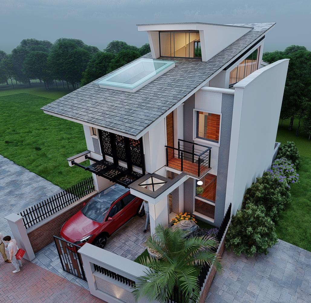
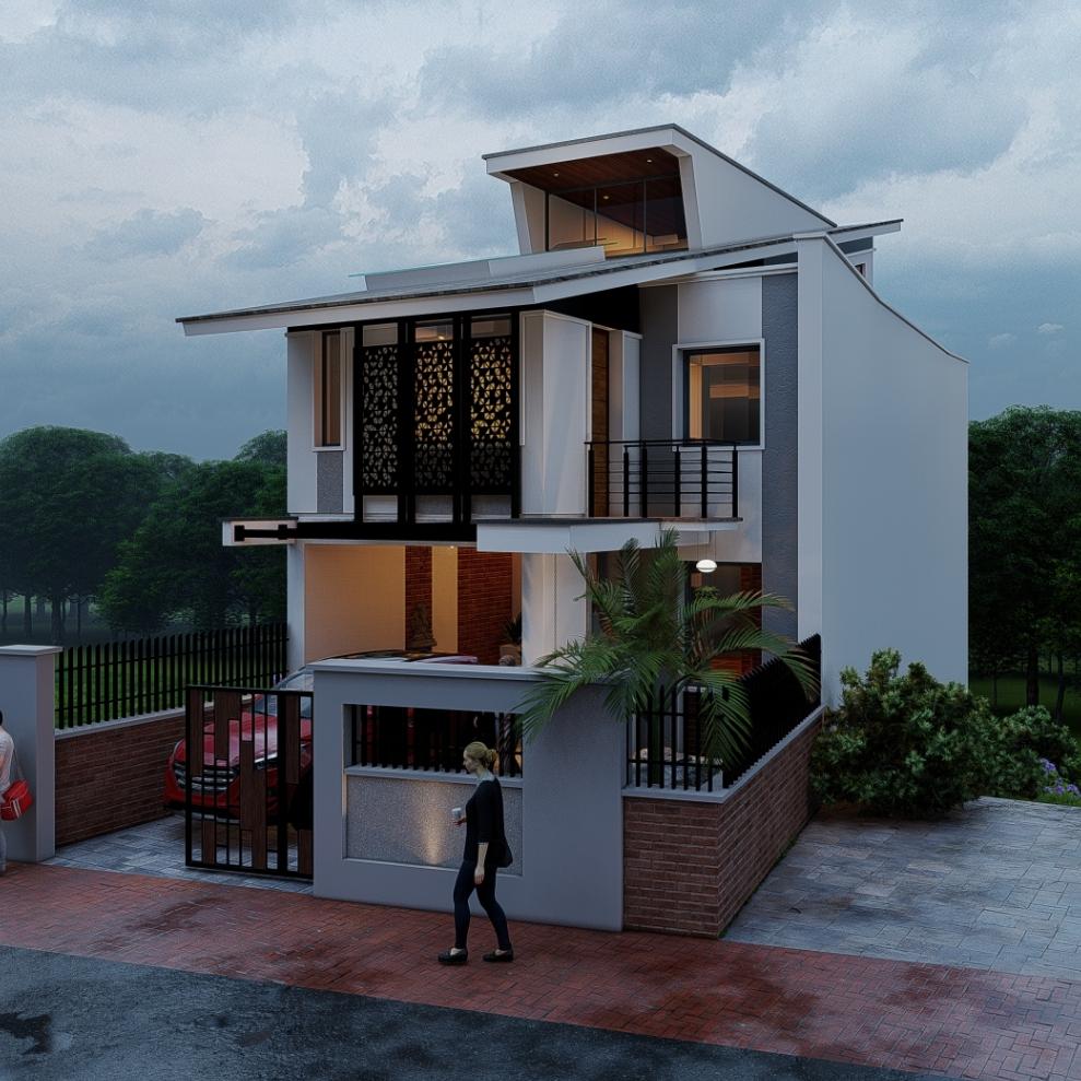
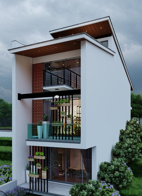
The primary objective of this project is to design and construct a distinctive farmhouse tailored to meet the specic needs and preferences of a bank manager. This residence, while seemingly straightforward, poses unique challenges due to its location on a complex site. The farmhouse will be situated on a naturally contoured terrain with three distinct elevations, each at varying heights, within a narrow horizontal space. Consequently, the design approach prioritizes creating an efcient and aesthetically pleasing building that integrates modern architectural elements, such as skillion and lean-to roofs. Additionally, the project incorporates shading mechanisms on the southern façade to effectively control sunlight exposure during daylight hours.
This project is driven by the specic requirement of our client, who desires a vacation farmhouse suitable for renting out to tourists seeking a holiday retreat. In alignment with the client's vision, a key requirement is the potential inclusion of a basement swimming pool, offering guests the unique and delightful opportunity to savor the breathtaking natural surroundings while indulging in a refreshing swim. Furthermore, the client has emphasized the necessity of a basement water tank within the project's specications. This water storage solution is vital for ensuring an uninterrupted and sustainable water supply, which is essential for meeting the needs of guests and maintaining the overall functionality and comfort of the farmhouse throughout their stay.

BY-LAWS
Ground Coverage = 70%
FAR = 2

Setback = 2m
ROW = 6m
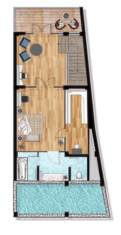
The basement plan reveals a thoughtfully designed living space, tailored for comfort and relaxation. It features a spacious bedroom complete with an ensuite bathroom and a convenient walkin closet, promoting privacy and convenience for the occupants The bedroom seamlessly connects to a cozy study room, providing an ideal workspace for reading, working, or simply unwinding. What s e t s t h i s s p a c e a p a r t i s i t s connection to a splendid deck area, where guests can revel in breathtaking scenic views while enjoying various activities. Safety is paramount, as evidenced by the surrounding shear wall protecting the water tank located to the south. Furthermore, the design ingeniously incorporates aesthetics and functionality by utilizing glass partitions rather than traditional brick walls in the bedroom and bathroom, enhancing the overall modern and open ambiance. This basement is impeccably suited for couples and tourists seeking a delightful retreat during their vacation.
0
1
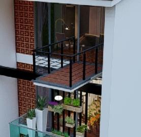

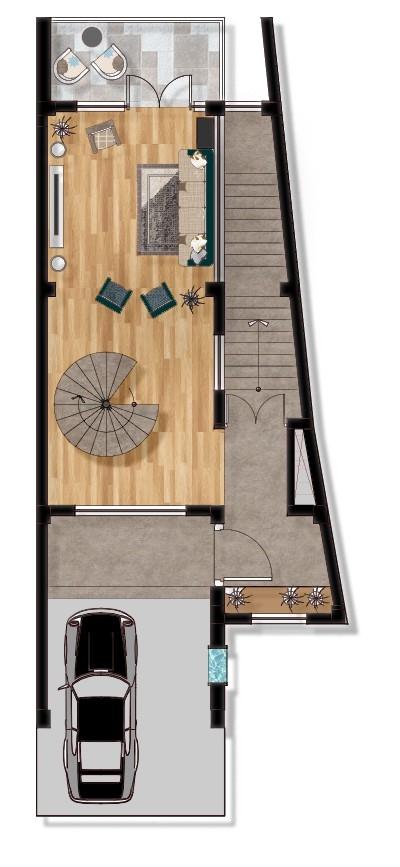
he main entrance to the farmhouse is accessed from the Teast direction, leading to a spacious ground oor with a distinct layout. Upon entering, you are presented with a choice to either proceed to the basement or stay on the ground oor. On the ground oor, a striking feature is a spiral staircase situated in close proximity to the entrance, offering an elegant focal point as well as easy access to other levels of the house. This oor primarily serves as a large living space, designed to promote an open and airy atmosphere It seamlessly connects to a balcony, extending the living area outdoors and providing a serene space for relaxation.
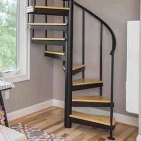

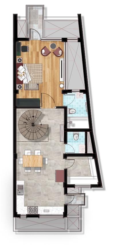
Continuing upwards to the second oor, you'll nd a well-appointed layout that offers both functionality and comfort. The highlight of this oor is the master bedroom, complete with an attached bathroom and a private balcony, providing a serene retreat for the occupants Adjacent to the bedroom, there is a thoughtfully designed kitchen and dining space that encourages communal g a t h e r i n g s a n d c u l i n a r y a d v e n t u r e s T o e n h a n c e organization and convenience, a dedicated storage room or pantry is incorporated into this area Additionally, to cater to the needs of guests and residents alike, an extra toilet is situated on this oor. The kitchen also boasts a small balcony, allowing for fresh air and natural light to ood the space while creating an ideal spot for a cozy morning coffee or herb garden.
My assignment involved translating an existing conceptual 3D design into detailed architectural drawings. These drawings were to be created following the rm's established drawing layers and standards. Additionally, I was tasked with developing a furniture layout based on my professional judgment. This involved determining the most functional and aesthetically pleasing arrangement of furniture within the designed spaces, considering factors like trafc ow and user comfort. Furthermore, adjustments to the foundation depths and building design were made in accordance with structural analysis ndings and specic client requirements.
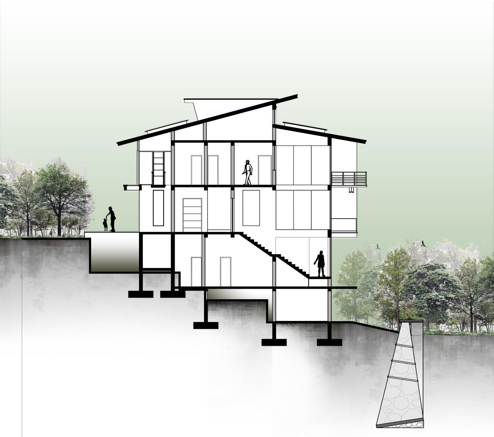
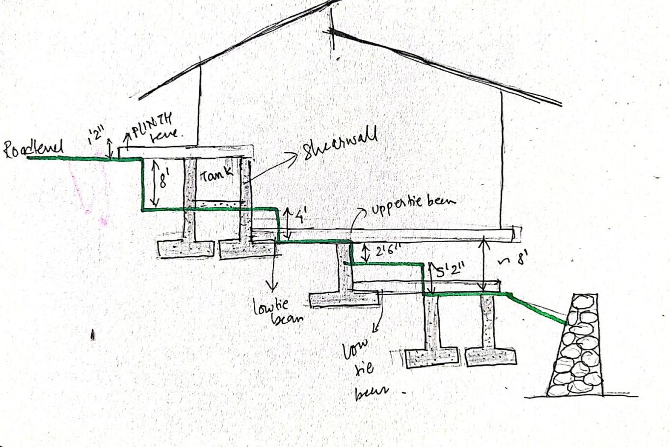
In the residence section, the diagram displays various levels of footings at different contour heights. The footings are categorized into two pairs at the top and bottom contours, with a single footing at the central contour. The lower tie beam of the topmost footing serves as the upper tie beam of the central one, and the lower tie beam of the central footing becomes the upper tie beam of the bottom footing. To support the soil, a retaining wall is constructed.


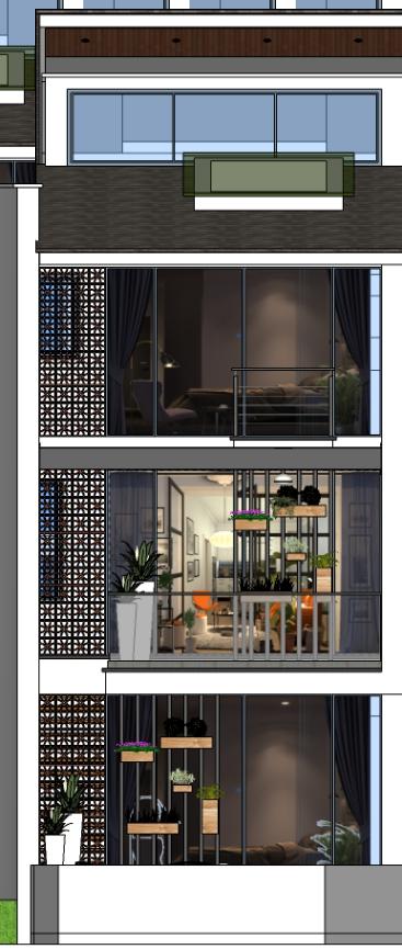
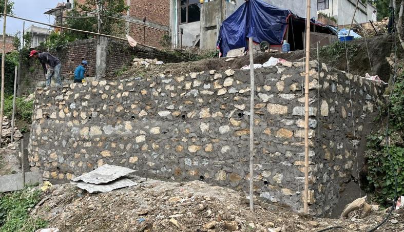
A retaining wall is a vital structural component in construction and landscaping that serves to retain or support soil or other materials, p r e v e n t i n g e r o s i o n a n d managing elevation changes in various outdoor settings. These walls come in a variety of materials, including concrete, wood, steel, or stone, each with its own aesthetic and functional advantages. Retaining walls are commonly used to create terraced landscapes on sloping terrain, provide structural support for buildings, roads, or gardens, a
r a l l appearance of outdoor spaces.
Here, the diagram above illustrates the details of the retaining wall. These retaining walls incorporate weep holes designed to alleviate the pressure and moisture exerted by the retained soil against the wall. As the wall's height increases, it gradually tapers down in size This intentional design minimizes the risk of the wall bending or toppling under the inuence of soil pressure, ensuring structural stability.
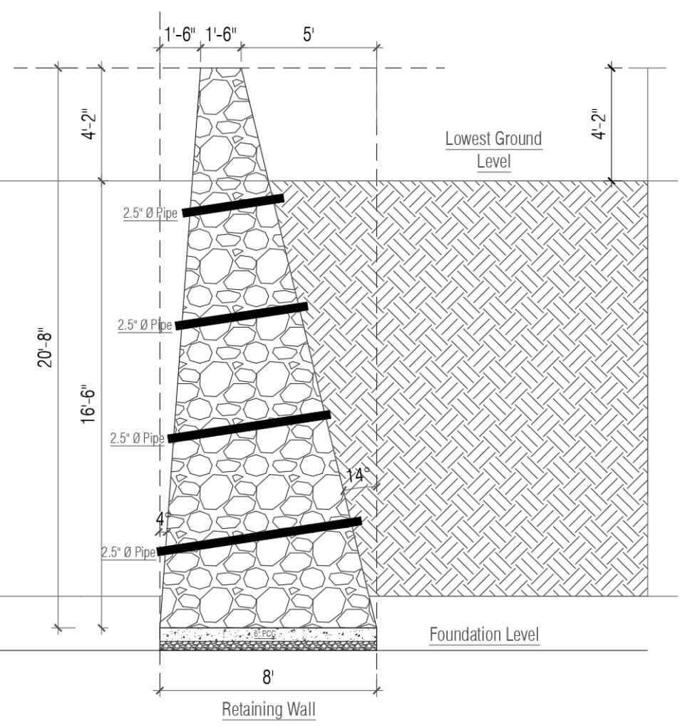
The weep holes are outtted with pipes, each having a diameter of 2 feet and 5 inches, facilitating the effective drainage of excess moisture from behind the wall. The retaining wall stands at a total height of 20 feet and 8 inches, with a width measuring 8 feet. Prior to the construction of this wall, a layer of placement of a 6-inch layer of PCC along with stone backlling. This meticulous preparation ensured a stable and level base upon which the retaining wall was constructed. The PCC layer and stone backlling collectively contribute to the structural integrity and long-term durability of the entire construction, providing a solid foundation capable of withstanding the pressures and demands of the retaining wall's signicant height.
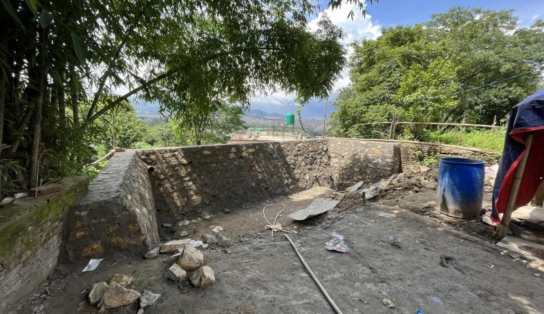
During the site visit, I observed that signicant progress has been made in the construction phase. The lower basement, designated for the swimming area, has been successfully completed, indicating substantial progress in the project's development. Additionally, the upper basement, with a notable oor height of 11’-4”, has been constructed with a staircase consisting of 20 steps, each having a 6.8” riser height, which is an important detail for accessibility and design considerations. Meanwhile, the lower basement stands at a height of 9’-4”, providing insights into the varying elevations within the structure.

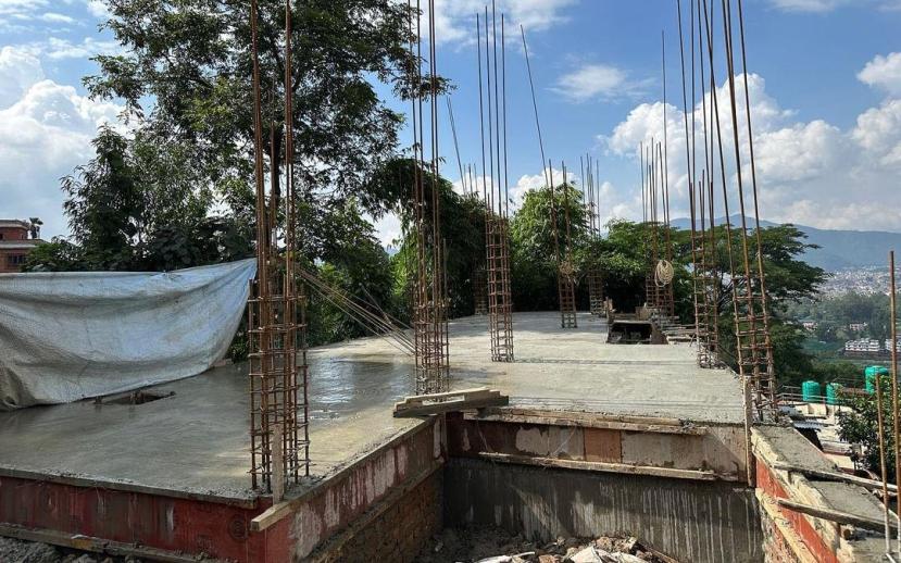
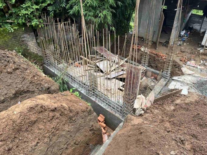
A combined footing is a type of foundation that supports two or more columns by sharing a single, continuous concrete slab beneath them. In this case, 8 dia. re-bar are used in the footing in 6” center to center spacing. PCC layer were already laid and column with development length and reinforcement were tied on the PCC layer and formwork were being prepared and after it, concrete mixture were prepared and laid over the formwork for the combined footing.
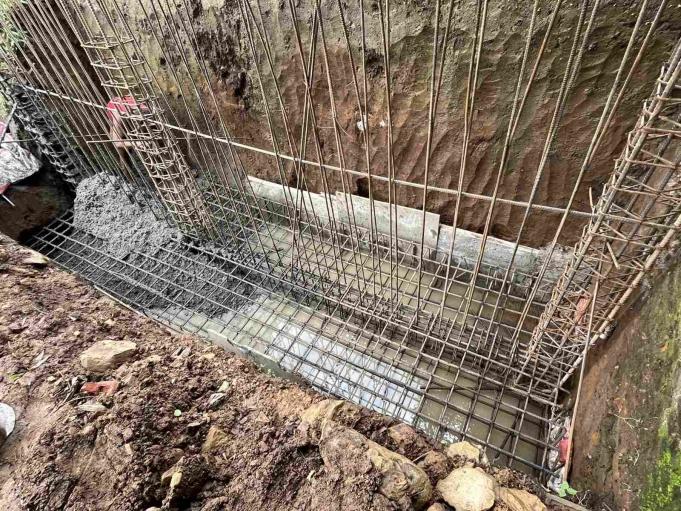
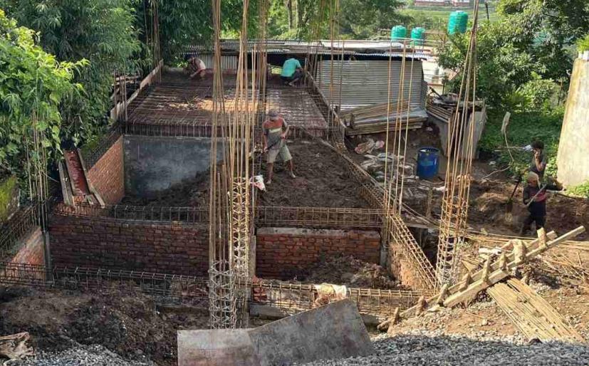
Backlling is the process of lling the voids or excavated areas around foundations, trenches, or structures with soil or other suitable materials. This is done to provide support, stability, and prevent settling or shifting of the structure. Backlling also helps in distributing loads evenly and improving drainage, ensuring the long-term integrity and safety of the construction project.
A shear wall in an underwater tank is a specially designed vertical structure within the tank's walls that provides resistance against lateral forces, such as water pressure. In this case, 8 dia. re-bar has been used horizontally and 10 dia. re-bar has been used vertically with 6” center to center spacing.
RCC casting is a crucial construction process involving the pouring and shaping of concrete mixed with steel reinforcement into desired molds or formwork. Proper curing and quality control are essential during RCC casting to achieve the desired strength and durability in the nished construction elements.
Through this experience, I've signicantly enhanced my prociency in CAD software, leveraging its capabilities for more efcient and precise design work. I've also acquired valuable knowledge on strategically arranging footing placements in alignment with site contours, optimizing structural stability and aesthetic harmony with the natural landscape. My understanding of retaining walls has grown, allowing me to integrate these crucial structural elements seamlessly into my projects. Furthermore, the invaluable insights gained from site visits during the initial construction phases have deepened my comprehension of the practical implementation of architectural concepts, providing me with a holistic perspective that extends beyond the drawing board These combined learnings have expanded my skill set and equipped me with a more comprehensive understanding of the architectural process from design to execution.
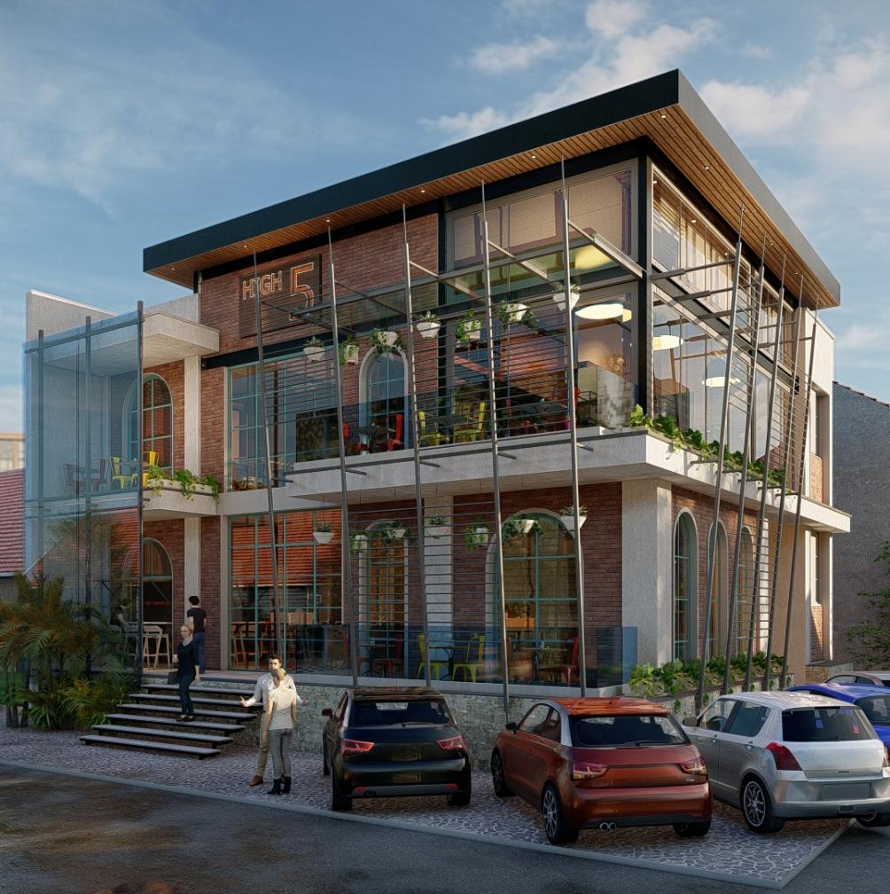
Mr. bibhu’s restaurant, chitwan Restaurant | 2605.25 sq.ft | ongoing
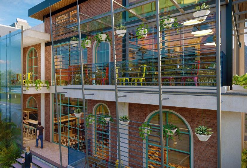
The primary objective of this project is to design and construct a distinctive restaurant tailored to meet the specic needs and preferences of businessmen. This project aims to conceptualize, develop, and successfully launch a modern restaurant that offers a contemporary dining experience. The application of restaurant concepts has enabled the creation of a space that caters to city residents of all ages. The concept of an open space serves as the foundation for the layout of tables and the ow of visitors within the restaurant. The restaurant is housed in a modern building with a pyramid hip roof design.
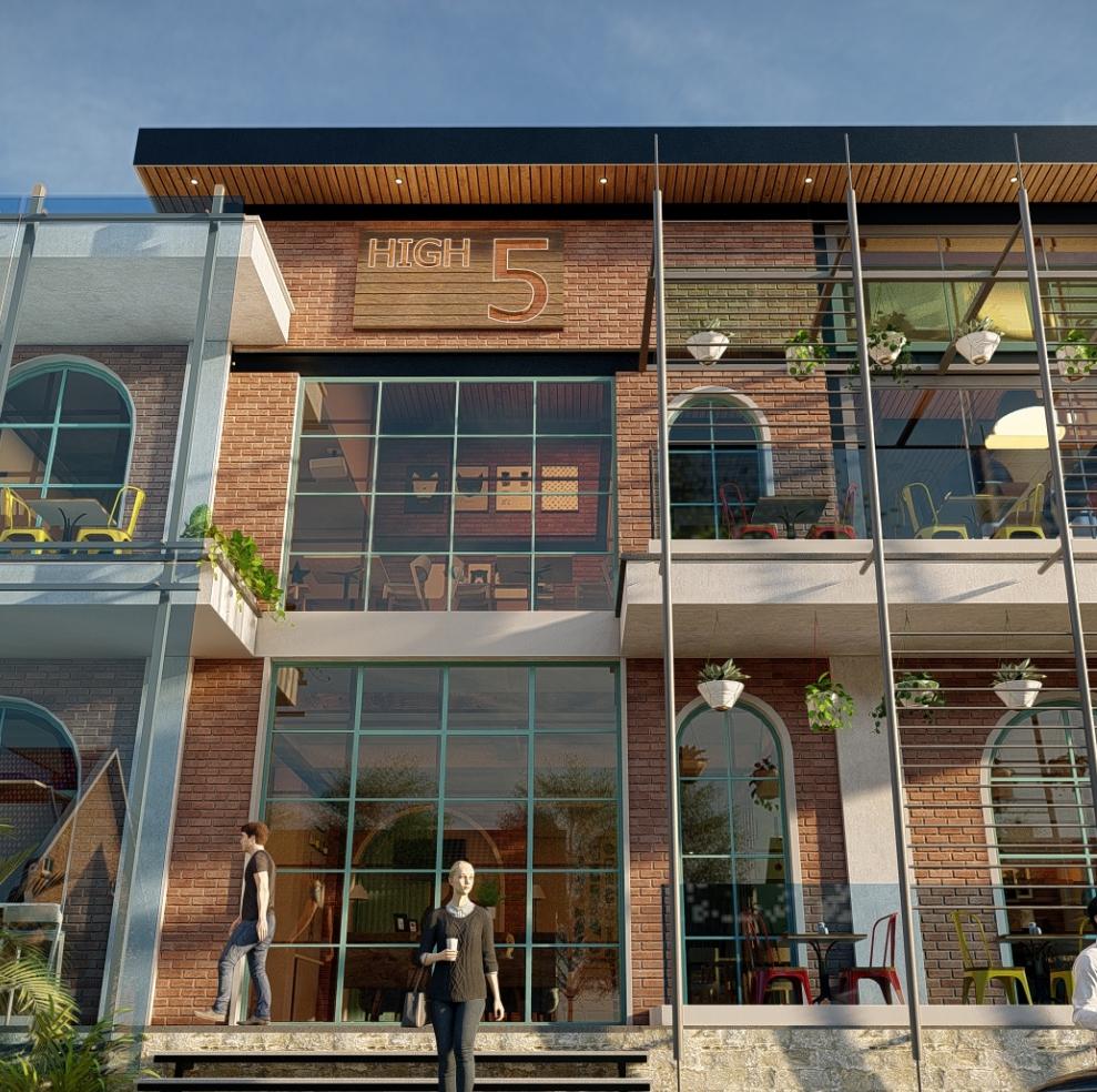
The client's key requirements for this project revolve around the establishment of a two-storey restaurant tailored to urban residents, including the essential provision of a basement for parking and service facilities. To maximize cost efciency, the client is open to the idea of integrating steel beams and columns into the restaurant's structural design. Furthermore, a paramount aspect of the client's vision is to embrace a retro-themed interior design aesthetic. In line with this, the client has specied the inclusion of key features within the restaurant, namely a pool table, a compact bar, a stylish bookshelf, and a dedicated stage area. These elements collectively represent the client's vision for a unique and engaging dining experience.
BY-LAWS
Ground Coverage = 60%
FAR = 2.5
Setback = 3m
ROW = 8m
4.

6.
7.
8.
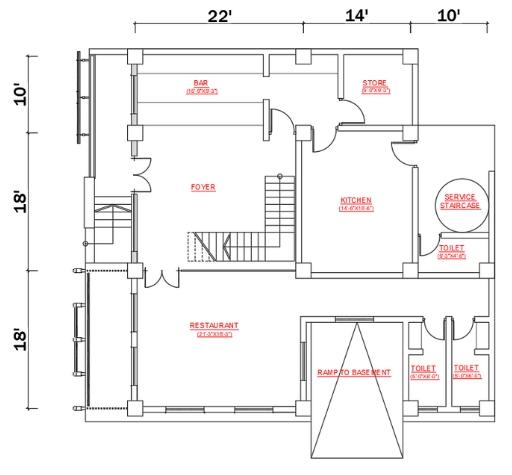
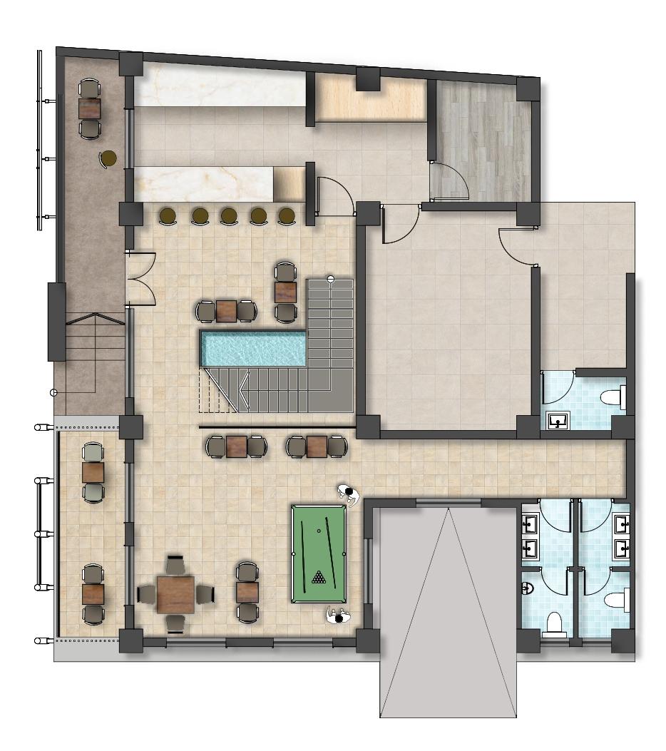
The restaurant's primary entrance is oriented towards the east, offering easy access for patrons. As guests step inside, they encounter the bar and counter area, strategically located in close proximity to the entrance for convenient service. Upon entering the main dining hall, a charming water fountain graces the space, surrounded by thoughtfully arranged seating areas to create a welcoming a n d v i s u a l l y a p p e a l i n g ambiance. Continuing into the main hall, there is a designated area featuring a pool table, providing an entertainment option for diners. Moving further east from the main hall, restrooms h a v e b e e n t h o u g h t f u l l y designed to cater to customer needs, ensuring comfort and convenience Additionally, the project includes well-planned spaces for the restaurant, ofce, and storage, all with easy access to a staff toilet facility situated in t h e e a s t e r n s e c t i o n . T h i s comprehensive layout optimizes the functionality and comfort of the restaurant while adhering to the client's specic requirements.

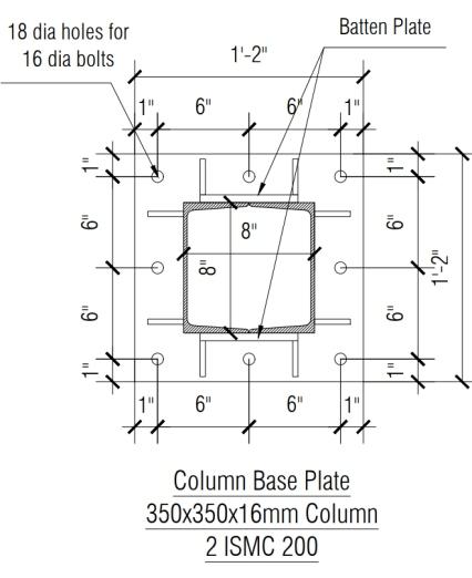
A column base plate is a structural component used in construction and engineering to connect a vertical column to its foundation or supporting structure It typically consists of a steel plate that is attached to the bottom of the column and a n c h o r e d t o t h e foundation or another structural element.

The rst oor of the restaurant has been thoughtfully laid out to p r o v i d e a v e r s a t i l e a n d enjoyable dining experience. It divides the space into two distinct dining halls and a central main hall, with a strategically positioned stage that serves m u l t i p l e p u r p o s e s , a c c o m m o d a t i n g s m a l l meetings, conferences, and intimate concerts while ensuring unobstructed views from all angles, including the primary dining area Glass partitions between these areas maintain a sense of separation while allowing for easy circulation. A balcony dining area adds charm and offers diners scenic views, and restrooms are conveniently located on the eastern side of the oor for guest comfort. This well-planned arrangement not only maximizes functionality but also creates an aesthetically p l e a s i n g a n d a d a p t a b l e atmosphere, catering to a range of dining preferences and event needs, making it an attractive destination for both residents and visitors.
2
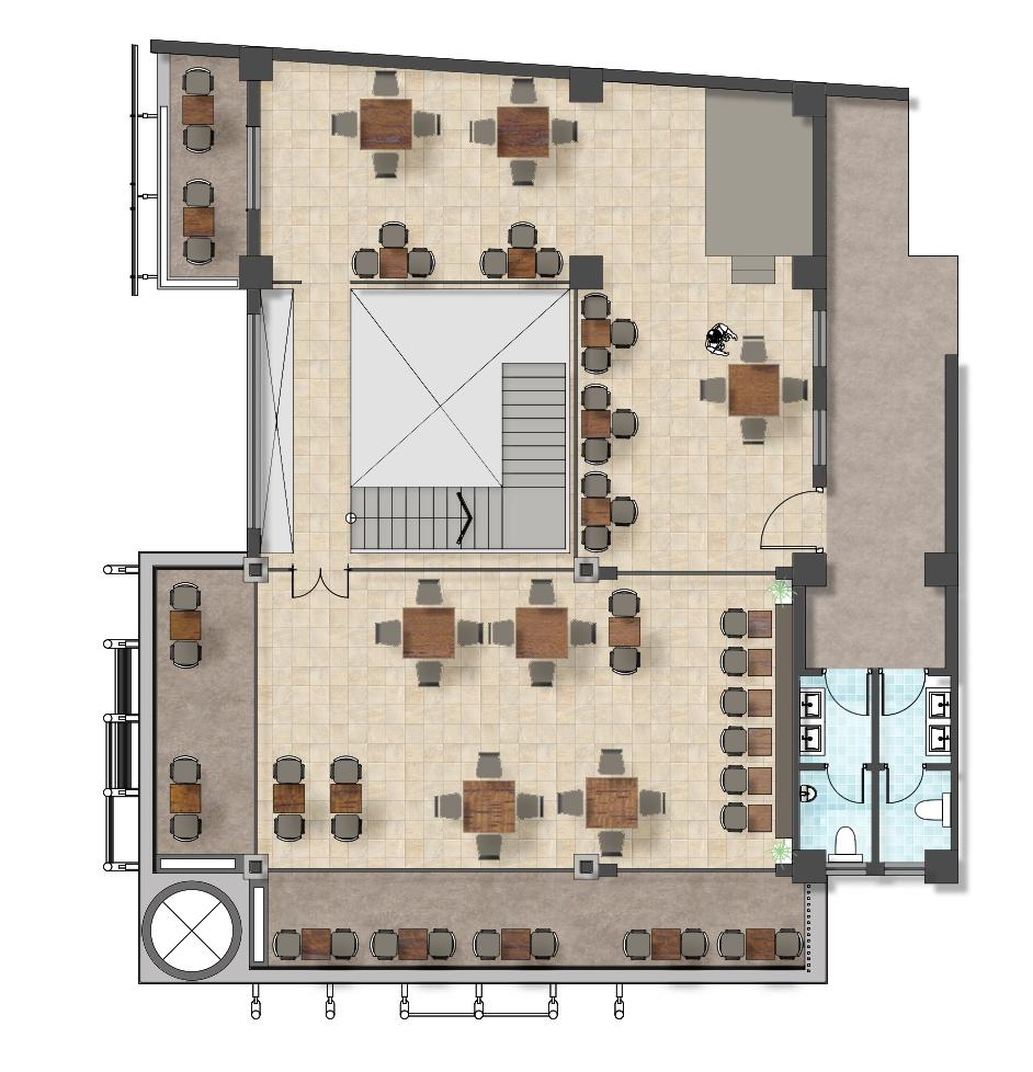
I have been assigned a project that entails revising the plans and sections of a restaurant due to adjustments in the grid's span This assignment also involves the conversion of an existing conceptual 3D design into meticulously detailed architectural drawings, following the specic drawing layers and standards set by our rm. Additionally, I have the responsibility of creating a furniture layout, determining the most functional and aesthetically pleasing arrangement of furniture within the designated spaces, while taking into account factors like trafc ow and user comfort. Furthermore, I've been tasked with calculating the oor height based on the number of steps required.
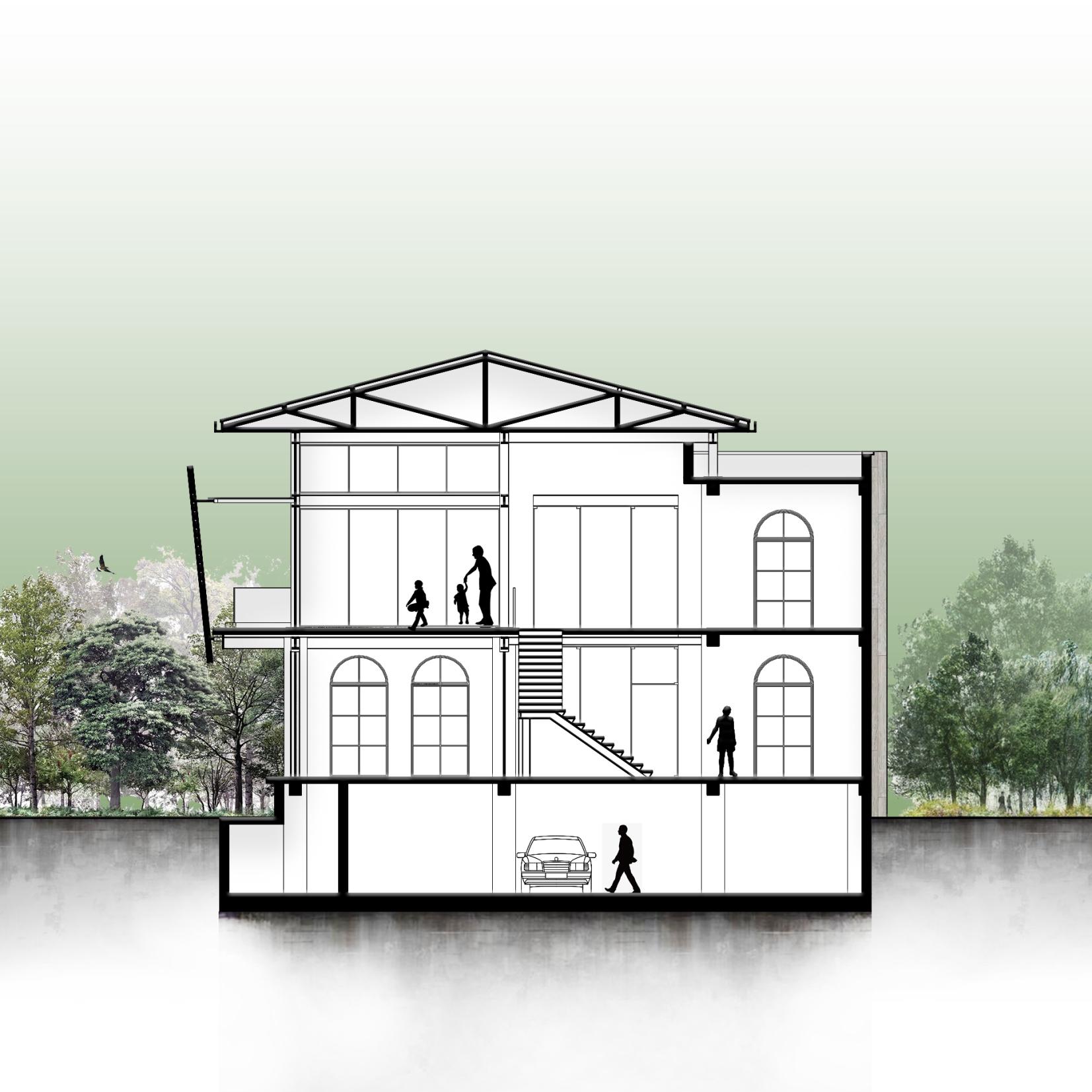
In the section, it's apparent that the basement serves a dual purpose, accommodating both parking spaces and service facilities. Furthermore, the inclusion of a metal staircase is noticeable, enhancing access within the structure. An interesting cost-saving measure is being implemented on the rst oor, where the original four columns are undergoing replacement with steel columns and beams, demonstrating an intention to economize on construction expenses while maintaining structural integrity.
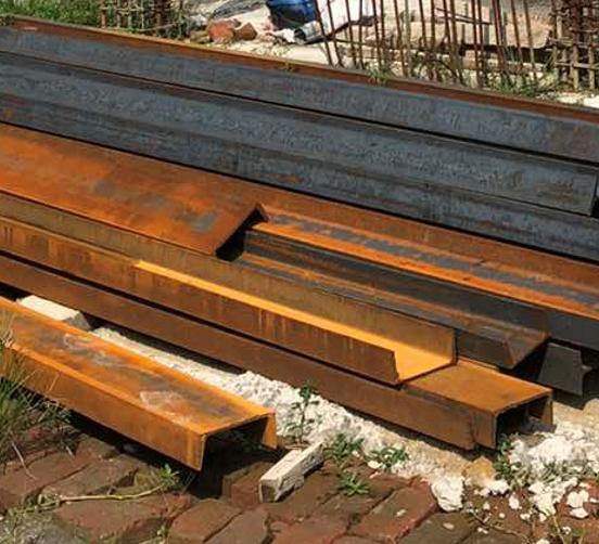
In gure 1, the detailed connection between the I-section beam and the Csection column is depicted In this conguration, two 200 x 200 mm ISMC sections are expertly welded side by side, forming a unied, larger structural post. This substantial post is then linked to the Isection beam through the use of a 6 mm llet weld and a 50 x 50 x 5 mm cleat. The llet weld, a frequently employed welding technique, is employed to effectively join the beam's anges to the open face of the column. This welding process ensures a robust and long-lasting connection, which is crucial for maintaining the structural integrity and strength of the overall framework.


Similarly, gure 2 demonstrates the detailed connection between the main steel beam and the secondary beam. Similar to the column connection, these beams are also securely joined using llet welds.

Wall Colour
Blinds Curtain

Mat Finish Farmaica
Sofa Texture

Column Colour
Dark Furniture
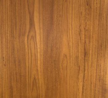
Texture for wooden post




Siyah Metal
Vaneer
Designer Floor Tiles

Porcelain Floor Tiles

Brick Facade
Wall Colour





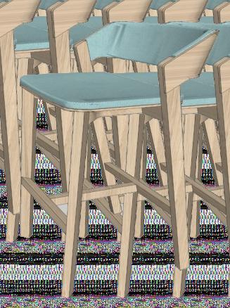


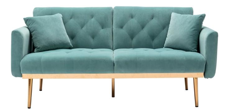 Designer Sofa
Dome Pendant Light
Plant
Mint Green Designer Sofa Plant
Long Arm Sconce
Wooden Bar Chair
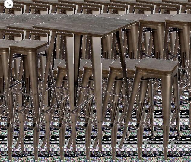
Metal-Wood Tall Table with Chair set
Photo Frame
Also, talking about the lightning, I’ve mainly focused on pendant lights, scondes, and track lightning each bringing their own unique qualities to a room illumination. Pendants offer versatile, hanging options with various styles, while sconces provide wall-mounted accents and space-saving designs. Track lighting, with adjustable xtures on a ceiling-mounted track, offers precise control and a modern aesthetic. Combining these lighting types strategically allows for a functional yet visually appealing lighting setup in any space.
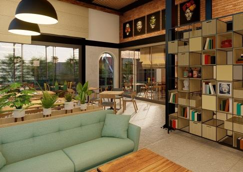
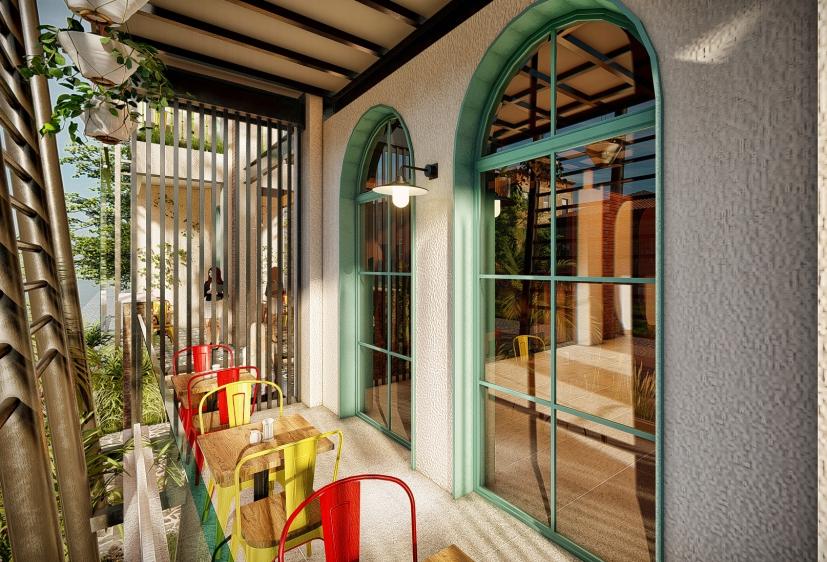
In my vision for this retro-themed interior, I've sought to create a seamless connection between the interior and the captivating brick facade of the exterior. To achieve this, I've meticulously incorporated elements such as graceful arches, w h i c h e l e g a n t l y a d o r n t h e handrails, walls, and partitions, mirroring the aesthetic charm of the arched windows on the outside. Collaborating closely with a seasoned architect, we've made thoughtful choices in materials, opting for the enduring appeal of metal accents that blend effortlessly with the warm, rustic character of sal-wood. For the color scheme, I've personally chosen mint green, creamy yellow, and pristine white to evoke a sense of nostalgia and sophistication throughout the interior. This project reects my dedication to creating a cohesive and visually pleasing living space that seamlessly marries retro aesthetics with modern comfort and functionality.
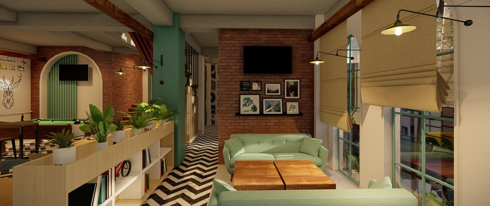
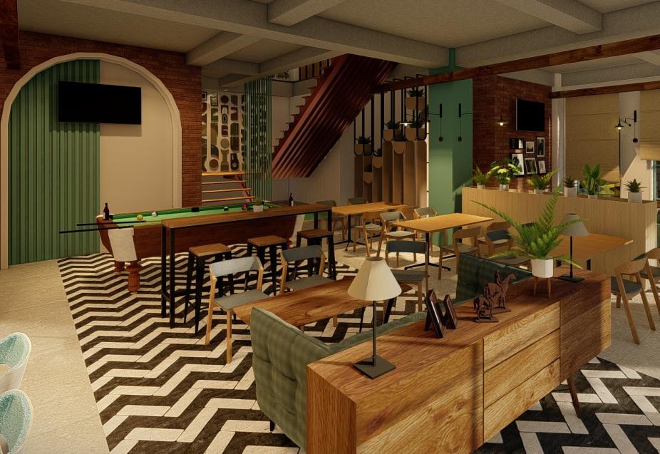
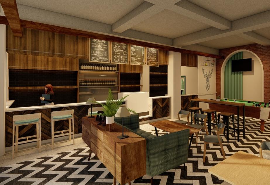
This project has been a rich learning experience, encompassing various aspects of architecture and interior design It's taught me the signicance of cost-effective structural decisions, such as opting for steel beams and columns, to ensure efciency without compromising on safety and durability. I've delved into the intricacies of restaurant furniture layout, discovering how the arrangement of furnishings impacts circulation and functionality, a crucial consideration for creating inviting and practical spaces. Additionally, I've honed my skills in rendering design les and gained insights into the art of material selection, vital for crafting cohesive and visually appealing interiors. Throughout this journey, the guidance of my senior architect has been instrumental in expanding my knowledge and expertise in these domains, setting a strong foundation for future projects and creative endeavors.
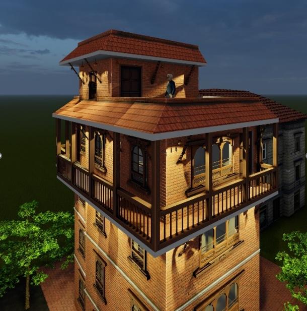
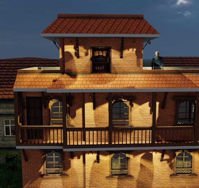
The primary objective of this project is to design and construct a distinctive residence tailored to meet the specic needs and preferences of local businessmen. This project aims to conceptualize and develop residence with traditional facade. The facade, a true masterpiece of craftsmanship, nds its essence in time-honored materials such as locally sourced bricks, featuring traditional windows that echo the aesthetics of a bygone era. Adding a touch of cultural authenticity, the project incorporates 'tuki' motifs in its lighting design, providing a warm and inviting ambiance that is both evocative and captivating. In harmonizing modern functionality with the beauty of Newari architecture, this residence promises to be a beacon of architectural excellence in the heart of Kirtipur, a testament to the enduring spirit of tradition.
As per the stipulated regulations governing the construction of this residence, the structure's height is meticulously restricted to a maximum of 45 feet, ensuring that it maintains a proportionate scale with the surrounding landscape. Furthermore, these guidelines mandate a generous setback of at least 1.5 meters (approximately 5 feet) on all three sides of the residence. At the front of the property, facing the road, an additional meter of setback is mandatory, allowing for an unobstructed view and enhancing the overall streetscape. In adherence to the principle of responsible land use, the regulations insist on a ground coverage of no more than 80 percent.

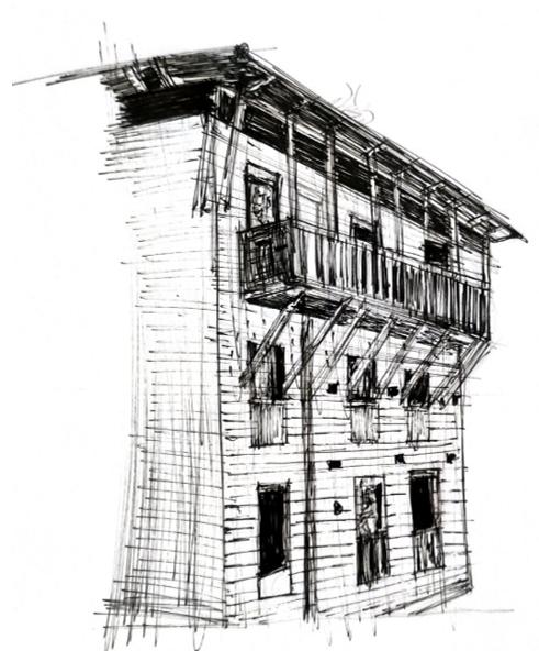

This project is driven by the specic requirement of our client, who desires a residence of a fourstory structure, with the ground oor reserved for a shop space. The driving force behind this design is the client's heartfelt desire for spaciousness. Given the substantial number of family members, the paramount consideration is the provision of ample room for everyone's comfort and convenience Additionally, because of the two contour levels on the site, the client wants the home entrance to be located on the upper level, while the entrance to the shop will be situated on the lower level.
Conceptual 3D
My assignment involved preparing the detail architectural drawings, sanitary drawings, electrical drawings and working drawings. I was also assigned the challenging responsibility of completing the structural drawings for this impressive residence. Guided by the experienced Senior Structural Engineer, I meticulously prepared detailed structural drawings for the entire building, all while under his expert supervision Moreover, I was entrusted with the crucial responsibility of estimating the total construction cost required for the project and meticulously crafting the bill of quantities.
To accommodate the client's desire for a four-story building while adhering to local bylaws specifying a maximum height of 45 feet, a creative solution was implemented The oor height was adjusted to 8 feet and 6 inches, with a total of 14 steps, each having a riser height of 7 inches. In alignment with the client's specic preferences, the m a i n e n t r a n c e w a s positioned on the upper level of the building, providing an elegant and distinctive entry point. Simultaneously, an additional entrance was integrated on the lower level, catering to the needs of the shop space and enhancing accessibility for customers and visitors.


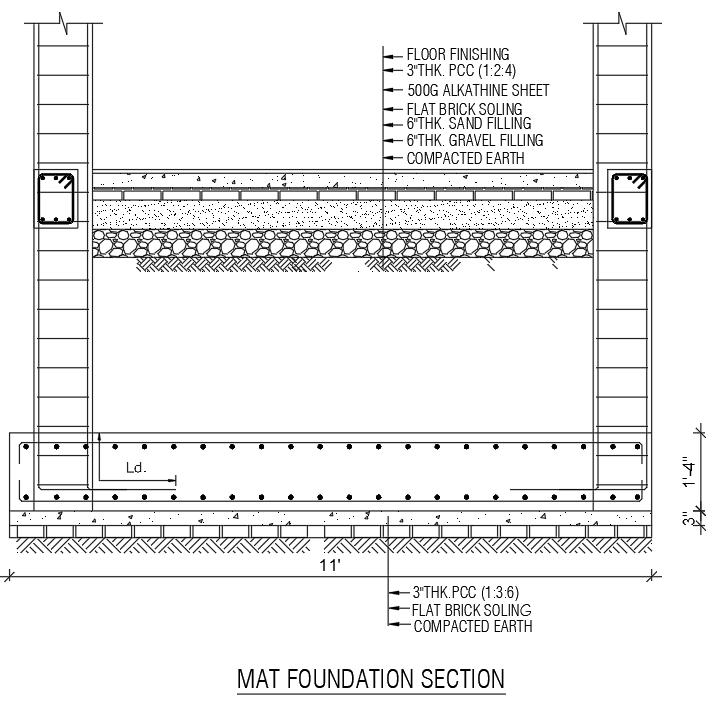
A mat foundation is a substantial concrete slab that uniformly distributes a building's load across the ground, rendering it well-suited for tall or heavy structures situated in regions with varying soil conditions or seismic activity In this context, the footing has a depth of 16 inches with the footing width measuring 11 feet Additionally, the provided gure also illustrates the oor nishing.
Slab Reinforcement bar length dened by calculation:
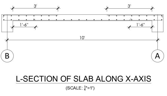

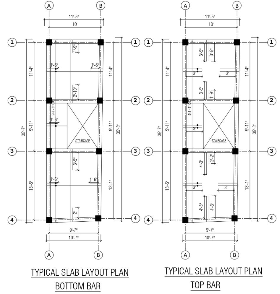
• When beam is placed at edge: 0.15 X C/C DISTANCE OF PILLAR
• When beam is placed at center: 0.3 X C/C DISTANCE OF PILLAR
When it comes to beam layout, there are two types of reinforcing bars:
through bars and extra bars. Through bars extend from one edge to another, while extra bars are used selectively, providing additional strength only where needed. Their length is calculated using the formula L/2.5, where 'L' represents the length of the beam.
Turning to the placement of stirrups in beams, it's essential to consider that bending moments are greater at the edges and supports compared to the middle section of the beam. As a result, stirrups are positioned closer together near the supports, typically within a distance of '2D,' where 'D' signies the depth of the beam. Typically, at the edges, stirrups are spaced 4 inches apart while in the middle section, they are spaced at a regular 6-inch interval, center to center.
Reinforcement Bar Size:
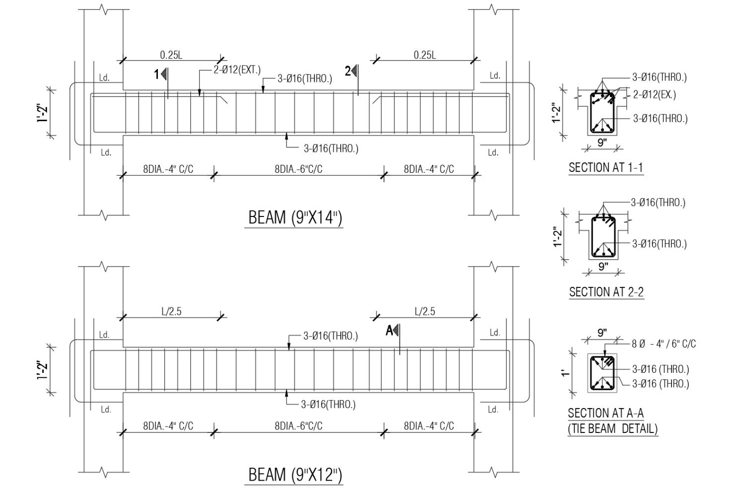
• 3 -16 DIA. BARS (THROUGHOUT)
• 2 -12 DIA. BARS (EXTRA BARS)
For more detail drawing refer to ANNEX
Providing & laying 75mm thick (1:3:6) cement, sand, stone chips-concrete and finishing the surface with floor hardner
FOURTH FLOOR
Lintel Band
• Above window and door frame to take load coming from wall,
• It may be of concrete, wooden, R.C.C., etc.
• The level of lintel is around 2.1m to 2.3m.
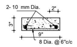
Sill Band
• Protects the junction of the window,
• Additional support and stability for the window,
• The level of sill is around 0.9m from oor level.
Providing & laying 75mm thick (1:3:6) cement, sand, stone chips-concrete and finishing the surface with floor hardner
THIRD FLOOR
Providing & laying 75mm thick (1:3:6) cement, sand, stone chips-concrete and finishing the surface with floor hardner
SECOND FLOOR
Interior plaster work (1:5) cement, sand mortar (1 2" thick) over RCC surface and wall in accurate line and level
Providing & laying 75mm thick (1:3:6) cement, sand, stone chips-concrete and finishing the surface with floor hardner
FIRST FLOOR
Providing & laying 75mm thick (1:3:6) cement, sand, stone chips-concrete and finishing the surface with floor hardner
PLINTH LEVEL
A shear wall is a vital structural element in building construction designed to resist lateral forces, such as wind, earthquakes, or other horizontal loads. Typically made of reinforced concrete or masonry, shear walls are strategically placed within a building to provide stability and prevent excessive swaying or deformation during external forces. In this context, the vertical re-bars have a diameter of 10mm, while the horizontal re-bars measure 8mm in diameter. These re-bars are positioned at a center-to-center distance of 6 inches.
3"THK.PCC (1:3:6)
After nalization of all the materials to be used in the superstructure, quantity estimation of the superstructure was done. A quantity estimate includes a list of quantities for all materials needed to complete a project. Its purpose is to give the client a complete list of all the quantities required for the project and what the cost will be for each quantity.
In words Sixty Three Lakhs Seventy-Two Thousand Seven Hundred and Five Rupees only
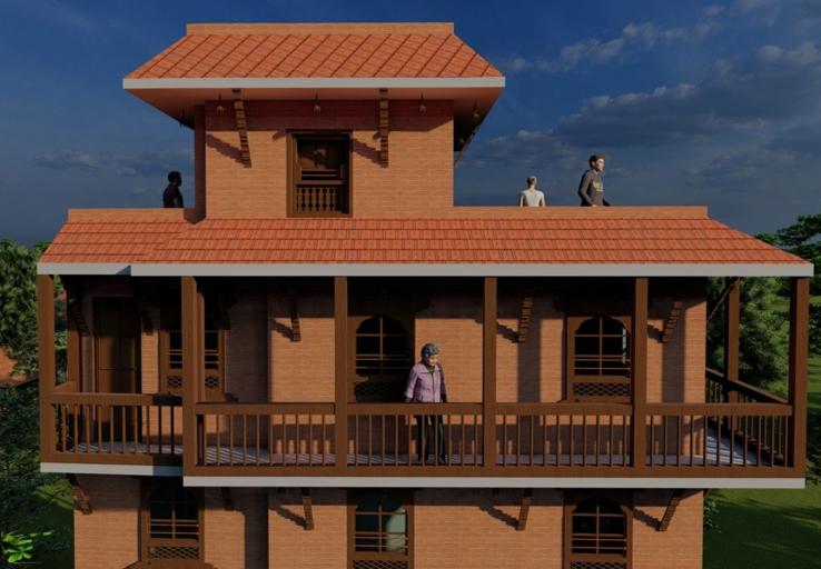
This project has been an invaluable learning experience for me, unveiling the art of designing and planning a residence within a conned space, showcasing the boundless possibilities of efcient spatial utilization Engaging in the creation of working drawings, I delved deep into the intricacies of architectural details, honing my understanding of essential elements such as lintel bands and sill bands. Furthermore, my collaboration with structural engineers illuminated the intricate world of structural drawings, equipping me with indispensable techniques and formulas for calculating development lengths and reinforcements, adding a new layer of depth to my knowledge. The assignment to estimate the bill of quantity was another enlightening task, expanding my expertise in construction materials, their rates, and types, fostering a holistic comprehension of the construction process. In sum, this project has been a treasure trove of knowledge, enriching my understanding of architecture, engineering, and construction management, and equipping me with a comprehensive skill set to tackle diverse challenges in the eld.
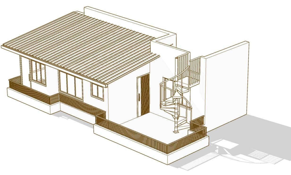

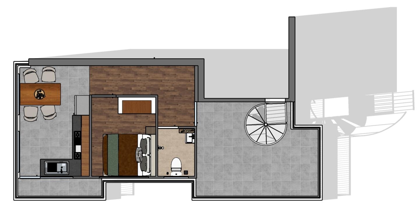
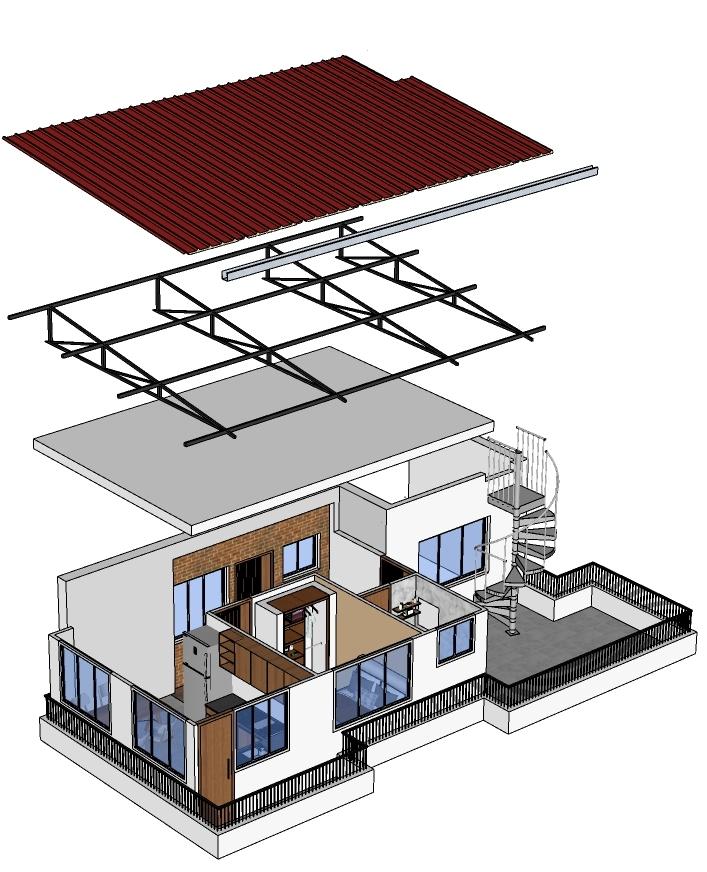
The primary requirement of our client is to create a home extension. This extension is intended for their personal use and comfort within their existing property, making it more suitable for their own needs and lifestyle. The client's vision includes the creation of a 1BHK (one-bedroom, hall, and kitchen) unit on their terrace. Additionally, they want to include a toilet, ensuring that the extension is fully equipped with basic amenities for comfortable living. The client desires to keep the project costeffective. To achieve this, they have expressed a preference for using pre-fabricated materials in the construction process. Prefabricated materials are known for their cost-efciency because they can reduce labor and construction time, ultimately saving money while maintaining quality.


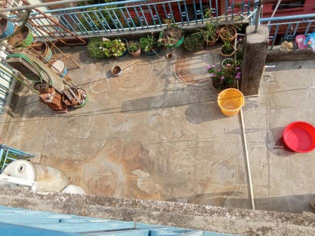
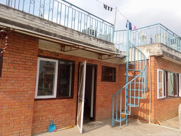

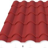
I was assigned the task of measuring the site and drafting a plan in accordance with the client's requirements As part of this responsibility, I conducted research to identify suitable pre-fabricated materials for the site. Subsequently, I engaged in discussions with the client regarding the proposed plan and the choice of materials. These discussions were a d y n a m i c e x c h a n g e o f i d e a s a n d considerations, where I had the privilege of presenting the intricacies of the plan and the merits of the chosen pre-fabricated materials.
1
In this project, meticulous and thoughtful planning took center stage, driven by the inherent constraints of limited space. Recognizing the spatial challenges, we embarked on a journey of creative problem-solving, which led to a strategic alteration in the placement of the staircase. This change proved pivotal, as it not only optimized space but also eliminated what had previously been a distracting element within the layout. Furthermore, our commitment to functionality and comfort extended to the kitchen area, where we introduced a small balcony. This clever addition not only enhanced the aesthetic appeal but also played a crucial role in facilitating proper air circulation, ensuring a fresh and inviting atmosphere in the heart of the home. These decisions exemplify how innovative design choices can maximize utility and aesthetics in even the most compact of spaces.

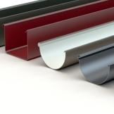

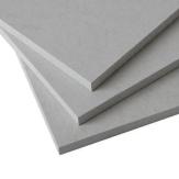
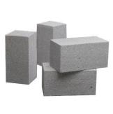
After nalization of all the materials to be used in the superstructure, quantity estimation of the superstructure was done. A quantity estimate includes a list of quantities for all materials needed to complete a project. Its purpose is to give the client a complete list of all the quantities required for the project and what the cost will be for each quantity.
BILLOF QUANTITY
Client Name - Mr.Krishna Maan Joshi
ProjectExtension of Prefabricated Works
LocationBuddhanagar , ktm
In words Seven Lakhs Sixty Five Thousand Eight Hundred and Seven Rupees only
This project has been an educational journey in various aspects of architecture. I've gained expertise in site measurements and translating them into precise AutoCAD drafts, a fundamental skill for accurate planning and execution Exploring diverse prefabricated materials has expanded my knowledge base, offering innovative solutions for construction. Interacting with the client has honed my communication and project management skills, crucial for meeting their needs and expectations. Furthermore, I've discovered the potential for building extensions on existing structures, particularly on terraces, using prefabricated materials, showcasing the adaptability and sustainability of modern architectural practices These experiences have enriched my architectural toolkit, equipping me to tackle complex projects with condence and creativity.