6 minute read
Warpage Simulation of Polymer Parts in Rotational Moulding


Large hollow seamless products of various size and shape are the hallmark of the rotational moulding process. Like all plastic processes, the processing parameters used to manufacture a rotationally moulded part can greatly influence the quality of the end-product. Perhaps some of the most critical parameters that govern part quality are the ones that control how the mould and product are cooled. If the mould is cooled nonuniformly, then this can induce thermal stresses into the part, even though the process is general thought of as being stress-free, as there is no pressure involved. In addition, if the cooling process is accelerated with the use of water for example, this can influence both the shrinkage rate experienced by the polymer and the final part shape. Of course, the application of release agent will play a major role as well. For thicker walled parts with long cooling cycles, it can be difficult to know what cooling parameters provide optimal cooling. This has led to researchers developing simulation models for process optimisation to achieve better productivity. For example, Crawford and Nugent[1] and Adams et al.[2] examined the unsteady heat transfer to identify optimum process variables through simulation. However, the warpage analysis was largely limited to experimental tests[3,4,5,6,7] and no simulation model for shrinkage and warpage existed prior to this work. Here, a novel approach using the thermal expansion coefficient (α) was used to predict warpage, with preliminary results presented by Seregar et al.[8] Iwakura et al.[9] determined that different mould materials and cooling methods exhibited different degrees of warpage and this work provided a numerical simulation solution. Extensive work investigating warpage analysis using different cooling techniques was also carried out by Tan.[10] which proved that the cooling rate of the polymer part plays a major role in warping of the part. The moulding data from some of the previous references was compared to the simulation results from this work. It should be noted that pressure has been shown to minimise part warpage[5,11], but the potential risk of damage to the mould requires appropriate safety measure are in place before this path should be considered. The simulation model in such cases can prove advantageous, saving time and money and can provide valuable feedback for process optimisation.
Simulation Model and Results
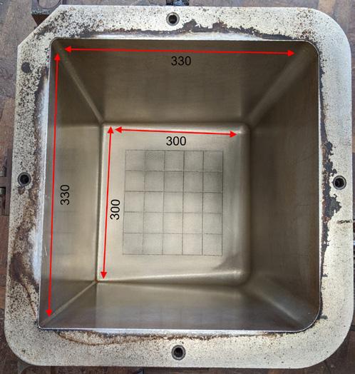
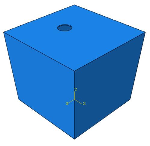
The sophisticated simulation of rotational moulding is difficult mainly because of unsteady heat transfer, lack of measured data (material and process parameters) and the motion of the mould. Additionally, the lack of information about the part conforming/ adherence to the mould surface makes the simulation modelling much more complex. In this simulation work, the 3D finite element modelling software Abaqus/Standard (Implicit solver) was used to model the process. A coupled temperature-displacement solver was adopted for modelling the cooling cycle, resulting in shrinkage and warpage predictions. A thermal expansion coefficient (TEC) approach was adopted for simulation of shrinkage and warpage[8]. The time-step size in transient (timedependent solution) is an important factor to avoid divergence in unsteady problems. Time incrementation can be controlled by the user or automatically by the Abaqus/Standard software. The time-step needs to be adjusted to 1e-6 (in the case of warpage simulation) to ensure the smooth convergence of the solution and the simulation program was executed at the supercomputer facility (HPC) at Queen`s University Belfast. In this work, we have presented warpage analysis of a drafted cube box mould used by Tan[10] as shown in Figure 1. The mould used had 10mm thick aluminium walls, with the overall dimensions shown in Figure 1 (a) and the HDPE part was 3 mm thick. The height of mould was 300 mm. The simulation begins with the cooling of the mould and polymer bed which are at a specified temperature (mould at 230°C and part at 220°C) down to a demoulding temperature (around 70°C). Heat is assumed to dissipate into the ambient air on either side of the surfaces. Edges and vent hole region are arrested from translation motion and an encastre boundary condition (rigid) is applied to the mould.
The linear-α modelling approach[12] is used in the simulation of the shrinkage and warpage model to predict the behaviour of polymer for different cooling conditions. A linear increase in the expansion coefficient is observed below the melting point[12] and the same trend is assumed to follow above melting point. The values constructed from this linear increase in expansion coefficient α for different cooling methods are presented in Table 1. It should be noted that during phase change of the material the expansion coefficient variation (rapid crystallisation effect) with temperature is not accounted for and will be presented in future work. Three cooling methods were used; forced external air (Ext air), external water (Ext Water), and external and internal water (EIW) cooling methods. The heat transfer coefficients were selected within the range as specified in the literature[12,13] for the simulation of these cooling conditions.
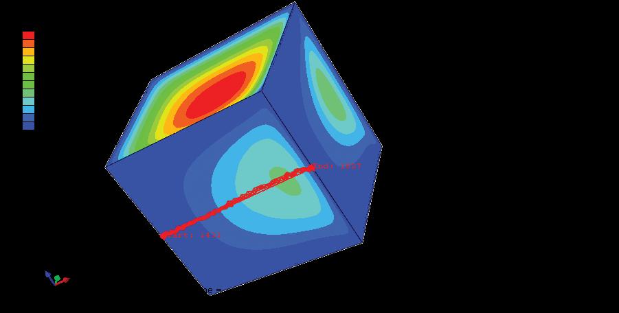
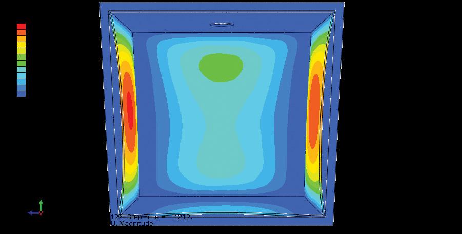
In the experimental measurement [10], warpage was measured at limited locations at the bottom surface of the part. However, simulation results enable analysing all the surfaces even on inner side of the part surface as shown in Figure 2 (a). Selected points as shown in Figure 2 (b) can be used to plot useful graphs like warpage at these points, as well as temperature, as presented in Figure 3. Table 2 summarises the warpage results against published experimental data by Tan[10] for three different cooling methods and they are in good agreement with each other. It can be concluded that cooling rate in the increasing order of their ability to warp the parts is defined in the relationship to follow, which corroborates the work of Bawishar and White[14]. Natural air connection <Mist/forced air <In. & Ext. water spray <water spray.
Conclusions
A novel method of linear-α based warpage simulation model accounting for temperature-based values was developed. It was used for warpage prediction under various cooling rates and the results are compared with experimental data in the referenced literature. Rapid external (Ext water) cooling of mould produced higher warpage in comparison to rapid internal and external cooling (EIW). EIW cooling method produced lesser warpage than in externally air-cooled parts. This analysis suggests if the cooling rate is controlled effectively on either side of the mould wall, faster cooling of part with minimum warpage can be achieved. An advanced α model considering crystallinity change during melt to solid phase change of polymer would provide a better warpage prediction. A future simulation model result will consider the effect of various thermo-mechanical properties of polymer and process parameters.
References
1. R.J. Crawford and P.J. Nugent, “Computer simulation of the rotational moulding process for plastics,” Plast. Rubber Process. Appl., vol. 11(2), pp. 107–124, 1989.
2. J. Adams, Y. Jin, D. Barnes, and J. Butterfield, “Simulation of the Rotational Moulding Process Using Discrete Element Methods,” 34th Int. Manuf. Conf., vol. 136, no. 1, pp. 23–42, 2021.
3. C.H.Chen, J.L.White, and Y.Ohta, “A fundamental experimental study of the mechanisms of warpage and shrinkage of polyethylene in rotational molding,” Int. Polym. Process., vol. 6(3), pp. 212–216, 1991.
4. Y.Ohta, C.H.Chen, and J.L.White, “Warpage in rotationallymoulded parts of polyethylene,” Kunststoffe Ger. Plast., vol. 79(12), pp. 42–44, 1989.
5. C. H. Chen, A. J.L. White, and Y. Ohta, “Mold pressurization as a method to reduce warpage in rotational molding of polyethylene,” Polym. Eng. Sci., vol. 30, no. 23, pp. 1523–1528, 1990.
6. SJ. Liu and CY. Ho, “Factors affecting the warpage of rotationally molded parts,” Adv. Polym. Technol., vol. 18(3), pp. 201–207, 1999.
7. L. Costa, M. C. Cramez, and A. J. Pontes, “A Study on shrinkage and warpage of rotational moulded polyethylene,” Mater. Sci. Forum, pp. 957–962, 2013.
8. J. Seregar, M. P. McCourt, M. P. Kearns, P. J. Martin, and G. Menary, “Simulation of Shrinkage and Warpage of Rotationally Moulded Polymer Parts,” Procedia Manuf., vol. 47, no. 2019, pp. 987–990, 2020.
9. K. Iwakura, Y. Ohta, A. C.H. Chen, and J. L. White, “A Basic study of warpage and heat transfer in rotational molding,” in ANTEC, 1989, pp. 558–562.
10. S.B. Tan, “Accelerated Cooling of Thermoplastics in Rotational Moulding,” Ph.D. Thesis at Queen’s University Belfast, 2010.
11. A. G. Spence and R. J. Crawford, “Removal of pinholes and bubbles from rotationally moulded products,” Proceed ings Inst. Mech. Eng. Part B J. Eng. Manuf., vol. 210, pp. 521–533, 1996.
12. S. B. Tan, P. R. Hornsby, M. B. McAfee, M. P. Kearns, and M. P. McCourt, “Internal cooling in rotational molding — A Review,” Polym. Eng. Sci., vol. 51, pp. 1683–1692, 2011.
13. J. L. Throne, SPE Topical Conference, 2004.
14. S. Bawiskar and J.L. White, “Comparative study of warpage, global shrinkage, residual stresses, and mechanical behavior of rotationally molded parts produced from different polymers,” Polym. Eng. Sci., vol. 34, pp. 815–820, 1994.


