Sheet Schedule

© THIS DRAWING IS THE COPYRIGHT OF DESIGNLABS LONDON LTD (DLL). It shall not be in any way used or reproduced or construct without their prior written consent. Al dimensions are to be checked on site by client or contractor prior to commencing any work. Work only to figured dimensions. Any discrepancies are to be reported to the DLL in writing and DLL shall not take responsiblity for site failing to inform discrepancies. Project : Drawing Scale Date : Rev Dwg No Status : ARCHITECTURE / INTERIOR / MANAGEMENT / PLANNING T: 07870661614 / 07888831314 E: info@designlabslondon.com W: www.designlabslondon.com DESIGNLABS LONDON Title Sheet - Sheet Schedule 16 Priory Road, Richmond TW9 3DF NC-GR0011/10/2022 Const
NC-GR00
NC-GR00-SC-001
NC-GR00-SP-100
11/10/2022
Issue
NC-GR00-SP-101 Specification 11/10/2022 Const Site Issue
NC-GR00-SP-102 Specification 11/10/2022 Const Site Issue
NC-GR01 Title Sheet- New Wall & Demolition Plan 11/10/2022 Const Site Issue
NC-GR01-DR-00-010 Ground Floor New Wall and Demolition Plan 11/10/2022 Const Site Issue
NC-GR01-DR-00-011 First Floor New Wall and Demolition Plan 11/10/2022 Const Site Issue
NC-GR01-DR-00-012 Second Floor New Wall and Demolition Plan 1 11/10/2022 Const Site Issue
NC-GR01-DR-01 Title Sheet- Sub-structure setting-Out Plans 11/10/2022 Const Site Issue
NC-GR01-DR-01-011 Sub-structure setting-Out Plans- Proposed Foundation Plan 1 11/10/2022 Const Site Issue
NC-GR02 Title Sheet- Setting-Out Sheets 11/10/2022 Const Site Issue
NC-GR02-DR-00-020 Setting-Out Plans'- Proposed Ground Floor Plan 2 11/10/2022 Const Site Issue
NC-GR02-DR-01-021 Setting-Out Plans'- Proposed First Floor Plan 1 11/10/2022 Const Site Issue
NC-GR02-DR-02-022 Setting-Out Plans'- Proposed Second Floor Plan 1 11/10/2022 Const Site Issue
NC-GR02-DR-XX-031 Setting-Out Sections'- Proposed Sections 1 11/10/2022 Const Site Issue
NC-GR02-DR-XX-032 Setting-Out Sections'- Proposed Sections 2 11/10/2022 Const Site Issue
NC-GR02-DR-XX-034 Setting-Out Sections'- Proposed Sections 2 11/10/2022 Const Site Issue
NC-GR02-DR-YY-035 Setting-Out Elevations'- Proposed Elevations 1 11/10/2022 Const Site Issue
NC-GR02-DR-YY-036 Setting-Out Elevations'- Proposed Elevations 11/10/2022 Const Site Issue
NC-GR02-DR-YY-037 Setting-Out Elevations'- Proposed Elevations 11/10/2022 Const Site Issue
NC-GR04 Title Sheet- Structural Drawing Sheets 11/10/2022 Const Site Issue
NC-GR04-DR-00-040 Proposed Ground Floor Structure 1 11/10/2022 Const Site Issue
NC-GR04-DR-01-041 Proposed First Floor Structure 1 11/10/2022 Const Site Issue
NC-GR04-DR-XX-045 Proposed Structural Sections 1 11/10/2022 Const Site Issue
NC-GR04-DR-XX-046 Proposed Structural Sections 1 11/10/2022 Const Site Issue
NC-GR04-DR-ZZ-047 Structural 3Ds 2 11/10/2022 Const Site Issue
NC-GR04-DR-ZZ-048 Structural 3Ds 2 11/10/2022 Const Site Issue
NC-GR05 Title Sheet- Building Elements Types and Schedule 11/10/2022 Const Site Issue
NC-GR05-SC-00-051 Under Floor Heating Schedule Page 1 of 2 11/10/2022 Const Site Issue
NC-GR05-SC-00-052 Under Floor Heating Schedule Page 2 OF 2 11/10/2022 Const Site Issue
NC-GR05-SC-00-055 Ground Floor- Flooring Plan and Schedule 11/10/2022 Const Site Issue
NC-GR05-SC-SC-056 Schedule- Wall, Floor and Roof Schedule 11/10/2022 Const Site Issue
NC-GR05-SC-SC-057 Window Schedule 2 11/10/2022 Const Site Issue
NC-GR05-SC-SC-058 Door Schedule 2 11/10/2022 Const Site Issue
NC-GR10 Title Sheet- Fire Safety Drawings 11/10/2022 Const Site Issue
NC-GR10-DR-00-100 Fire Safety Plans'- Proposed Ground Floor Plan 11/10/2022 Const Site Issue
NC-GR10-DR-02-102 Fire Safety Plans'- Proposed Second Floor Plan 11/10/2022 Const Site Issue
NC-GR12 Title Sheet Plumbing & Drainage 11/10/2022 Const Site Issue
NC-GR12-DR-00-120 Plumbing & Drainage Plans - Proposed Ground Floor Plan 11/10/2022 Const Site Issue NC-GR12-DR-XX-125 Plumbing & Drainage 3D 11/10/2022 Const Site Issue
NC-GR12-DR-XX-126 Bathroom Detail 11/10/2022 Const Site Issue
NC-GR12-DR-XX-127 Bathroom Detail 11/10/2022 Const Site Issue
NC-GR12-DR-XX-128 Bathroom Concept 14/10/2022 Const Site Issue
NC-GR13 Title Sheet- Lighting RCPs 11/10/2022 Const Site Issue
NC-GR13-DR-00-130 Lighting RCPs Plans - Proposed Ground Floor RCP 11/10/2022 Const Site Issue NC-GR13-DR-02-133 Lighting Notes 11/10/2022 Const Site Issue
NC-GR14 Title Sheet Electrical & Small Power Layouts (With Furniture) 11/10/2022 Const Site Issue NC-GR14-DR-00-141 Ground Floor Small Power layout 11/10/2022 Const Site Issue
© THIS DRAWING IS THE COPYRIGHT OF DESIGNLABS LONDON LTD (DLL). It shall not be in any way used or reproduced or construct without their prior written consent. Al dimensions are to be checked on site by client or contractor prior to commencing any work. Work only to figured dimensions. Any discrepancies are to be reported to the DLL in writing and DLL shall not take responsiblity for site failing to inform discrepancies. Project : Drawing Scale Date : Rev Dwg No Status : ARCHITECTURE / INTERIOR / MANAGEMENT / PLANNING T: 07870661614 / 07888831314 E: info@designlabslondon.com W: www.designlabslondon.com DESIGNLABS LONDON Sheet Schedule 16 Priory Road, Richmond TW9 3DF NC-GR00-SC-00111/10/2022 Const Project No: Project: 16 Priory Road, Richmond TW9 3DF Drawings Issue Sheet Sheet Number Sheet Name Current Revision Sheet Issue Date Project Status Sheet Status
Title Sheet Sheet Schedule 11/10/2022 Const Site Issue
Sheet Schedule 11/10/2022 Const Site Issue
Specification Sheets Title
Const Site
Specification
© THIS DRAWING IS THE COPYRIGHT OF DESIGNLABS LONDON LTD (DLL). It shall not be in any way used or reproduced or construct without their prior written consent. Al dimensions are to be checked on site by client or contractor prior to commencing any work. Work only to figured dimensions. Any discrepancies are to be reported to the DLL in writing and DLL shall not take responsiblity for site failing to inform discrepancies. Project : Drawing Scale Date : Rev Dwg No Status : ARCHITECTURE / INTERIOR / MANAGEMENT / PLANNING T: 07870661614 / 07888831314 E: info@designlabslondon.com W: www.designlabslondon.com DESIGNLABS LONDON Specification Sheets Title 16 Priory Road, Richmond TW9 3DF NC-GR00-SP-10011/10/2022 Const
GENERAL CONSTRUCTION NOTE TO COMPLY THE CONSTRUCTION WITH BUILDING REGULATION
GENERAL
THE FOLLOWING SPECIFICATION MUST BE READ IN CONJUNCTION WITH ALL ARCHITECTURAL GENERAL ARRANGEMENT DRAWINGS, SCHEDULES ETC. AND IS APPLICABLE WHETHER SPECIFICALLY REFERRED TO OR NOT. IT IS THE RESPONSIBILITY OF THE CONTRACTOR/SUB-CONTRACTOR TO ENSURE THAT ALL THEIR WORK IS IN COMPLIANCE WITH THE APPROPRIATE REQUIREMENTS OF THE RELEVANT BUILDING REGULATIONS, NHBC STANDARDS AND OTHER ALLIED LEGISLATION.
ALL MATERIALS ARE TO BE USED AND INSTALLED IN ACCORDANCE WITH THE RELEVANT MANUFACTURER'S INSTRUCTIONS AND RECOMMENDATIONS. ALL NEW SERVICES ARE TO BE PROVIDED IN ACCORDANCE WITH THE STATUTORY UNDERTAKER'S REQUIREMENTS. THE QUALITY OF ANY MATERIAL SHALL NOT BE LOWER THAN THAT DEFINED IN THE RELEVANT BRITISH STANDARD, OR THAT THE MATERIAL HAS BEEN SATISFACTORILY ASSESSED BY AN APPROPRIATE INDEPENDENT AUTHORITY I.E. BBA, BRE.
THE CONTRACTOR/SUB-CONTRACTOR MUST ENSURE THAT MATERIALS ARE 'FULLY SUITABLE' FOR THEIR LOCATION AND THAT ALLIED MATERIALS/BACKGROUNDS ARE APPROPRIATE. WHERE THERE IS NO LEGISLATED STANDARD, THE QUALITY AND USE OF THE PRODUCT SHALL BE IN ACCORDANCE WITH ESTABLISHED SATISFACTORY CUSTOMS AND PRACTICES. ALL WORK SHALL BE CARRIED OUT IN A SOUND, NEAT, DURABLE AND WORKMANLIKE MANNER. REASONABLE PRECAUTIONS SHALL BE TAKEN TO PROTECT FIXED AND UNFIXED MATERIALS AGAINST ANY DAMAGE LIKELY TO AFFECT THE FINISHED QUALITY OF THE BUILDING.
ALL CONTRACTORS/SUB-CONTRACTORS MUST ENSURE TO THEIR OWN SATISFACTION THAT THEY ARE IN POSSESSION OF THE CURRENTLY ISSUED DRAWINGS AND DETAILS, BEFORE COMMENCING THE RELEVANT 'WORK-STAGE' ON SITE.
NOTE: UNLESS STATED ALL CONSTRUCTION DETAILS ARE TO BE IN ACCORDANCE WITH THE ROBUST DETAILS DOCUMENT - LIMITING THERMAL BRIDGING AND AIR LEAKAGE PUBLISHED BY DTLR.
THE PRINCIPLE CONTRACTOR IS TO ENSURE THAT THE PROVISIONS OF THE CONSTRUCTION DESIGN MANAGEMENT (CDM) REGULATIONS ARE CARRIED OUT FULLY, INCLUDING ALL NOTIFICATIONS OF WORK REQUIRED UNDER LEGISLATION, PRIOR TO START OF WORKS.
FOUNDATIONS
THE EXISTING GROUND WITHIN THE EXTENT OF THE PROPOSED BUILDING CONSTRUCTION SITE SHALL BE CLEARED OF ALL TURF AND VEGETABLE MATTER PRIOR TO ANY FURTHER EXCAVATION BEING MADE. METHOD OF DISPOSAL OF ANY CONTAMINATED SOIL TO BE AGREED WITH THE LOCAL ENVIRONMENTAL OFFICER. FOUNDATION TRENCHES SHALL BE CLEAN AND TRUE AND CHECKED FOR SOFT AREAS, WATER ETC. AND LEFT WITH COMPACTED BOTTOMS.
FOUNDATIONS SHALL BE LOCATED CENTRALLY UNDER EXTERNAL AND LOAD BEARING INTERNAL WALLS UNLESS IS IT INDICATED IN ARCHITECTURAL DRAWINGS. ALL FOUNDATIONS SHALL BE DESIGNED WITH DUE REGARD TO SUBSOIL CONDITIONS, WATER TABLE, PRESENCE OF SULPHATES AND PREVIOUS GROUND USES ETC. DEPTH OF THE FOUNDATIONS TO SUIT SOIL CONDITIONS, ORIGINAL AND PROPOSED GROUND LEVELS, DRAINAGE TRENCHES AND PROXIMITY OF TREES/HEDGES, ALL TO THE SATISFACTION OF THE RELEVANT BUILDING CONTROL AUTHORITY/NHBC INSPECTOR. READY MIXED CONCRETE WILL ONLY BE ACCEPTABLE FROM SUPPLIERS USING A FULL QUALITY CONTROL SYSTEM.
ENTIRE FOUNDATION DESIGN TO BE IN-ACCORDANCE WITH STRUCTURAL ENGINEERS DESIGN DRAWINGS AND CALCULATIONS.
CONTRACTOR / SUB-CONTRACTOR TO MAKE SURE THERE IS NO ENCROACHMENTS ON SITE.
BELOW GROUND DRAINAGE
ALL DRAINAGE WORKS SHALL BE IN FULL ACCORDANCE WITH APPROVED DOCUMENT H OF THE BUILDING REGULATIONS, BS 8301 AND TO THE COMPLETE SATISFACTION OF THE RELEVANT BUILDING CONTROL BODY.
WHERE DRAINS PASS THROUGH EXTERNAL WALLS THEY ARE TO BE PROTECTED WITH A PRE-STRESSED CONCRETE LINTEL OVER (AS DESIGNED BY ENGINEER) WITH MIN. 150MM END BEARINGS, WITH 150MM CLEARANCE ALL ROUND PIPE AND THE OPENING IS TO BE MASKED WITH RIGID SHEET MATERIAL TO PREVENT THE INGRESS OF VERMIN OR FILL.
IF APPLICABLE, REFER TO DRAINAGE ENGINEER'S DETAILED DRAWINGS FOR DRAINAGE LAYOUT AND SPECIFICATION DETAILS.
GROUND FLOOR CONSTRUCTION
GROUND FLOOR CONSTRUCTION AS INDICATED IN ARCHITECTURAL GENERAL ARRANGEMENT DRAWINGS AND TO BE CONFIRMED BY ENGINEER.
GROUND BEARING FLOOR 75MM REINFORCED SAND/CEMENT SCREED (UNDER FLOOR HEATING TO SPECIALIST'S DESIGN - TO BE CONFIRMED BY THE END USE) ON 1200G POLYTHENE PROTECTION LAYER ON 100MM GA4000 CELOTEX INSULATION (FF4000 FOR UNDER FLOOR HEATING) OR SIMILAR APPROVED ON 1200G DPM ON 200MM REINFORCE-CONCRETE GROUND FLOOR SLAB WITH MESH REINFORCEMENT WITH MIN. 50MM COVER, (SEE ENGINEER'SDRAWING), ON BRICK BALLAST/CRUSHED STONE BASE ON WELL COMPACTED SOIL. 25MM CELOTEX INSULATION STRIP TO BE PROVIDED TO ALL PERIMETER WALLS. CONSTRUCTION TO ACHIEVE UVALUE OF 0.18
PLEASE NOTE FOR EXTENSIONS ANY EXISTING FLOOR VENTS TO BE CONNECTED WITH 4" PIPE AND VENTED TO EXTERNAL LEAF.
MOVEMENT JOINTS
REFER TO FLOOR PLANS AND STRUCTURAL ENGINEERS DETAILS FOR RECOMMENDED LOCATION OF MOVEMENT JOINTS TO OUTER LEAF BRICKWORK/BLOCKWORK, GENERALLY TO BE PROVIDED AT NOT GREATER THAN 6 METRE CENTRES FOR BLOCKWORK AND 12-15 METRE CENTRES FOR BRICKWORK. MOVEMENT JOINTS TO BE 10MM MINIMUM WIDE, LOCATED BEHIND RAIN WATER DOWN PIPES WHERE POSSIBLE AND FORMED WITH PROPRIETARY POLYURETHANE SEALING STRIP, WITH FLAT TIES BETWEEN PANELS AT 450MM VERTICAL CENTRES WITH ONE END DE-BONDED WITH POLY-SULPHIDE SEALANT TO EXTERNAL FACE OF BRICKWORK - COLOUR TO MATCH. NOTE : PROVIDE CAVITY WALL TIES WITHIN 150MM HORIZONTALLY, AT 225MM MAXIMUM VERTICAL CENTRES, EITHER SIDE OF MOVEMENT JOINTS.
EXTERNAL CAVITY WALL
CAVITY WALLS TO COMPLY WITH BS 5628. 325MM EXTERNAL WALL CONSTRUCTION ABOVE DPC COMPRISING 100MM AIRCRETE BLOCKWORK (TC 0.11) INNER SKIN, STRENGTH TO BE 7.3 N/MM.SQ, 12.5MM PLASTERBOARD ON DABS, STRICTLY IN ACCORDANCE WITH THE MANUFACTURER'S RECOMMENDATIONS. ALL WALLS ARE TO RECEIVE A PLASTER SKIM FINISH READY TO RECEIVE DECORATION.
CAVITY TO BE FULLY FILLED WITH 115MM KINGSPAN K107 CAVITY INSULATION OR SIMILAR APPROVED IN ACCORDANCE WITH MANUFACTURERS DETAILS. OUTER LEAF GENERALLY TO BE 102.5MM (FL DURABILITY) FACING BRICKWORK TO MATCH EXISTING. TOTAL EXTERNAL CAVITY WALL TO ACHIEVE MINIMUM 'U' VALUE 0.16 W /M2K.
LOWER CAVITY IS TO BE FILLED WITH A LEAN MIX CONCRETE UP TO A LEVEL OF 225MM MINIMUM BELOW DPC & IS TO BE LAID WITH SULPHATE RESISTANT MORTAR. PROVIDE PERPEND WEEPHOLES EVERY FOURTH VERTICAL JOINT IN THE OUTER LEAF AT THE BASE OF THE CAVITY AT 150MM BELOW D.P.C.
PROVIDE PROPRIETARY INSULATED CAVITY CLOSERS AT ALL WINDOW/DOOR OPENINGS AND CLOSE CAVITY AT TOP WITH INSULATED LINTEL.
ROOF CONSTRUCTION
ROOF DESIGNER/STRUCTURAL ENGINEER TO BE RESPONSIBLE FOR THE DESIGN OF THE WHOLE FOR THE ROOF INCLUDING ALL NECESSARY WIND BRACING ETC IN ACCORDANCE WITH BS5268: PART 3. ROOF TIMBERS DESIGNED AROUND A 200MM DEEP RAFTER.
ROOFING TILES AS SPECIFIED IN ARCHITECTURAL DRAWINGS (TO BS 5534 PT.1 AMENDED 1981) LAID WITH PITCH AND LAP IN ACCORDANCE WITH MANUFACTURER'S INSTRUCTIONS ON 50X38MM SW BATTENS (SIZE TO BE N ACCORDANCE WITH BS 5534) ON 'TYVEK SUPRO' OR SIMILAR APPROVED VAPOUR PERMEABLE BREATHER MEMBRANE. MEMBRANE DRESSED INTO GUTTERS ON 'TYVEK' EAVES CARRIER. ON SW PRE FABRICATED TRUSSED RAFTERS AND BRACINGS TO BS 5268 PART 3 1985, AT MAX 600 CTS. 30X5G.S RESTRAINT STRAPS AT VERGE AND CEILING LEVEL. PROVIDE AND BED ON 1:1:6 MORTAR 100X50MM SW TREATED WALL PLATE WITH RESTRAINT STRAPS TO WALL PLATE AT MAX 2 M CTS. TO BS 5628 PART 1. ALL EXTERNAL TIMBERS TO BE PRESERVATIVE TREATED.
FLAT ROOF LOFT VOID - ROOF INSULATION TO FLAT CEILING AREAS TO BE 200MM GLASS FIBRE INSULATION QUILT LAID IN 2 LAYERS. 100MM LAID BETWEEN TRUSSED RAFTERS/CEILING JOISTS AND 1 LAYERS 100MM IN CEILING VOID UNDER ROOF JOISTS
THE FIRST LAYER IS TO EXTEND THROUGH EAVES TO BUTT AGAINST THE CAVITY CLOSER AT THE TOP OF THE EXTERNAL WALL.
FLAT ROOF AT RAFTER LEVEL (WARM FLAT ROOF) FIBER GLASS WATER PROOFING LAYER OR SIMILAR APPROVED TO MANUFACTURER'S INSTRUCTIONS AND DETAILS. ON 18MM OSB 3 BOARD, ON 120MM KINGSPAN TR26 RIGID INSULATION OR SIMILAR APPROVED WITH VAPOUR CONTROL LAYER ON BOTH SIDES, ON 12MM OSB2 BOARD, ON SW FURRINGS TO GIVE MINIMUM 1:60 FALL, ON 175MM JOISTS (AS SPECIFIED BY ENGINEER), 15MM CEILING BOARD WITH VAPOUR CONTROL LAYER, CONSTRUCTION TO ACHIEVE U-VALUE OF 0.15
GREEN ROOF BUILD-UP: (IN ABEYANCE)
ALLOW FOR CUTTING THE OVERHANGING RAFTER FEET SQUARELY TO ACHIEVE PERFECT VERTICAL ALIGNMENT TO THE NEW FASCIA BOARDS, AS WELL AS A CONSTANT SOFFIT WIDTH.
TRUSSES TO BE SECURED TO WALL PLATES USING PROPRIETARY TRUSS CLIPS WITH NAILS FIXED THROUGH EACH AVAILABLE HOLE.
FORM HIPS AND RIDGE USING PROPRIETARY RIDGE AND BONNET HIP TILES, & CODE 5 LEAD ON VALLEY BOARDS IN ACCORDANCE WITH LEAD ASSOCIATION DETAILS,(ALTERNATIVELY A GRP VALLEY CAN BE USED AND INSTALLED STRICTLY IN ACCORDNACE WITH MANUFACTURES / SUPPLIERS GUJIDLINES AND RECOMMENDATIONS.
DAMP PROOF COURSE
HORIZONTAL DAMP PROOF COURSE TO BE MINIMUM 150MM ABOVE ADJACENT GROUND LEVEL. A SECONDARY DPC WILL BE PROVIDED 150MM ABOVE FLOOR LEVEL FOR MINIMUM DISTANCE OF 1.5M FROM ALL EXTERNAL DOORS WITH A LEVEL THRESHOLD. DPC/ CAVITY TRAY TO BE MARLEY AQUAGARD OR SIMILAR APPROVED AND IS TO BE INSTALLED STRICTLY IN ACCORDANCE WITH THE MANUFACTURERS INSTRUCTIONS AND RECOMMENDATIONS.
IF THE EXTERNAL GROUND LEVEL IS EQUAL OR ABOVE THE INTERNAL FINISH FLOOR LEVEL, THEN DOUBLE DPC TO BE PROVIDED, ONE AT FINISHED FLOOR LEVEL AND THE SECONDARY 150MM ABOVE EXTERNAL GROUND LEVEL. BOTH HORIZONTAL DPC'S TO BE CONNECTED WITH AND VERTICAL LAYER OF DPC ALL IN ACCORDANCE WITH ARCHITECTURAL DESIGN AND DETAILS.
CAVITY CLOSURE TO ALL WINDOWS AND DOORS TO REPLACE ALL VERTICAL DPC'S AND IN ORDER TO AVOID COLD BRIDGING.
THE HORIZONTAL DAMP PROOF COURSE SHALL CONSIST OF A LAYER OF 2000 GAUGE POLYTHENE DAMP COURSE TO BS 743/6515 ADEQUATELY LAPPED AT CORNERS AND JOINTS AND LAID ON A MORTAR BED.
WHERE EXTERNAL WALL CAVITY IS BRIDGED I.E. AIR BRICK/VENTILATOR OPENINGS AND METER CUPBOARD ETC. PROVIDE POLYTHENE CAVITY TRAYS COMPLETE WITH STOP ENDS OVER IN THE EXTERNAL WALL WITH OPEN PROPRIETARY PERPENDS. CAVITY TRAYS ARE TO PROJECT 150MM BEYOND EITHER SIDE OF LINTEL/OPENING.
AT ALL ROOF ABUTMENTS I.E PORCHES, GARDEN ROOMS ENSURE STEPPED D.P.C'S CAVITY TRAY WITH STOP ENDS ARE PROVIDED AND LINKED TO CODE 4 LEAD FLASHINGS AND SOAKERS. CODE 4 LEAD DRESSED BENEATH CAVITY TRAYS AND OVER ROOF SLOPES WITH ALTERNATE PERPENDS LEFT OPEN FOR WEEPHOLES ALL AS NECESSARY TO FORM WEATHER PROOF JUNCTION. ALL LEADWORK TO SOAKERS, FLASHINGS, VALLEYS ETC. ARE TO BE IN COMPLIANCE WITH THE RECOMMENDATIONS OF THE LATEST EDITION OF THE LEAD SHEET ASSOCIATION'S 'GUIDE TO GOOD PRACTICE'.
INTERNAL WALLS
INTERNAL PARTITIONS TO BE BRITISH GYPSUM 'GYPWALL' METAL STUD-PARTITIONING SYSTEM OR APPROVED TIMBER STUDS. FOR TOTAL OVERALL THICKNESS AND BUILD-UP SEE WALL SCHEDULE. METAL /TIMBER STUDS AT 600MM CTRS. .
PARTITIONS PARALLEL TO THE SPAN ARE TO BE LOCATED ON MULTIPLE JOISTS WHERE POSSIBLE AS RECOMMENDED BY ENGINEERED JOIST MANUFACTURER AND STRUCTURAL ENGINEER, OR SUPPORTED BY CLIPPED NOGGINS AS DETAILED BY MANUFACTURER..
ADDITIONAL 12.5MM STRUCTURAL PLY BOARD TO BE ADDED BETWEEN/ABOVE BATTENS TO SUPPORT THE KITCHEN/BATHROOM FITTINGS AND APPLIANCES.
PROVIDE CAVITY TRAYS & CODE 4 STEPPED AND APRON LEAD FLASHINGS AT ABUTMENTS OF ALL ROOFS WITH WALLS, LEAD CHASED INTO WALLS AND WEDGED AT MAXIMUM 450MM CENTRES AND POINTED IN 1:3 CEMENT/ SAND MORTAR. PROVIDE SOAKERS TO HIPS, VALLEYS AND ROOF/ WALL ABUTMENTS.
PROVIDE CAVITY TRAYS & CODE 4 STEPPED AND APRON LEAD FLASHINGS AT ABUTMENTS OF ALL ROOFS WITH WALLS, LEAD CHASED INTO WALLS AND WEDGED AT MAXIMUM 450MM CENTRES AND POINTED IN 1:3 CEMENT/ SAND MORTAR. PROVIDE SOAKERS TO HIPS, VALLEYS AND ROOF/ WALL ABUTMENTS.
© THIS DRAWING IS THE COPYRIGHT OF DESIGNLABS LONDON LTD (DLL). It shall not be in any way used or reproduced or construct without their prior written consent. Al dimensions are to be checked on site by client or contractor prior to commencing any work. Work only to figured dimensions. Any discrepancies are to be reported to the DLL in writing and DLL shall not take responsiblity for site failing to inform discrepancies. Project : Drawing Scale Date : Rev Dwg No Status : ARCHITECTURE / INTERIOR / MANAGEMENT / PLANNING T: 07870661614 / 07888831314 E: info@designlabslondon.com W: www.designlabslondon.com DESIGNLABS LONDON Specification 16 Priory Road, Richmond TW9 3DF NC-GR00-SP-10111/10/2022 Const
WINDOWS AND DOORS
WINDOWS: UPVC WINDOWS STYLE TO MATCH AS INDICATED ON ARCHITECTURAL DRAWINGS. ALL FIRST FLOOR WINDOWS AND ABOVE TO BE DESIGNED WITH EASY CLEAN HINGES TO ALLOW FOR CLEANING EXTERNAL GLAZING FROM WITHIN ROOM. NO WINDOW OPENINGS FIRST FLOOR AND ABOVE TO BE LESS THAN 800MM ABOVE FINISH FLOOR LEVEL UNLESS SAFETY GLAZING & GUARDING, (REFER TO AD N1 AND GLAZING SPECIFICATION BELOW), PROVIDED TO AT LEAST THE HEIGHT OF 800MM FROM FFL. CHILD RETRACTORS TO BE FITTED.
WINDOWS/EXTERNAL DOORS TO ALL HABITABLE ROOM UPTO 4.5M FROM GROUND LEVEL TO BE EMERGENCY EGRESS WINDOWS WITH UNOBSTRUCTED OPENABLE AREA 0.33M² WITH MIN 450X450MM OPENING AND BOTTOM OF OPENING NOT MORE THAN 1100MM FROM FFL, ALL INACCORDANCE WITH AD PART B.
PROVIDE TRICKLE VENTILATOR UNITS TO HEAD OF WINDOWS PROVIDING 2500MM2 EQUIVALENT TO HABITABLE ROOMS AND STRICTLY ACCORDANCE WITH AD PART F.
WINDOWS TO BE FITTED TO PROVIDE A 30MM EXTERNAL REVEAL FROM THE FACE OF BRICKWORK AND TO OVERHANG CAVITY CLOSURES BY A MINIMUM OF 30MM.
DOORS: PROPRIETARY MADE. PROVIDE LEVEL THRESHOLD IN COMPLIANCE WITH BUILDING REGULATION REQUIREMENTS PART M, ACCESS FOR THE DISABLED
FRONT ENTRANCE DOORS TO BE PROVIDED WITH A LEVEL THRESHOLD AND RAMPED ACCESS IN ACCORDANCE WITH AD PART M.
DRAUGHT STRIPPING TO ALL EXTERNAL DOORS AND WINDOWS. MASTIC TO BE APPLIED BETWEEN FRAMES AND BRICKWORK INTERNALLY AND EXTERNALLY.
WINDOWS AND DOORS TO ACHIEVE A U-VALUE OF 1.6 W/M2K.
EXTENDED CILLS OF APPROPRIATE LENGTH ARE TO BE ALLOWED FOR AREAS OVER RENDER TILE HANGINGS/ STUB CILLS TO BE PROVIDED FOR WINDOWS ABOVE STONE CILL
GLAZING
ALL GLAZING TO WINDOWS BELOW 800MM AND GLAZING TO DOORS BELOW 1500MM INCLUDING SIDELIGHTS WITHIN 300MM HORIZONTALLY TO BE FITTED WITH LAMINATED SAFETY GLAZING TO BS 6206 : 1981. ALL HEIGHTS TO BE MEASURED FROM FINISHED FLOOR LEVEL.
GLAZING TO BE INSTALLED IN FULL ACCORDANCE WITH AD PART L OF THE BUILDING REGULATIONS. 24MM DOUBLE SEALED GLAZED UNITS WITH LOW E GLASS TO BE USED. OBSCURE GLASS TO WC AND BATHROOM WINDOWS.
SMOKE ALARMS
AUTOMATIC MAINS OPERATED SELF-CONTAINED SMOKE DETECTORS WITHIN EACH UNIT CONFORMING TO BS 5446 TO BE PROVIDED TO CEILINGS AT LOCATIONS INDICATED ON THE PLANS. ALARMS TO HAVE PERMANENTLY WIRED CONNECTION WITH BATTERY BACK UP, INTERLINKED ONE AT EACH FLOORAND PROVIDED WITH SEPARATE FUSED CIRCUIT AT DISTRIBUTION BOARD IN ACCORDANCE WITH CURRENT IEE REGULATION. ALARMS TO BE LOCATED MINIMUM 300MM CLEAR FROM ANY WALL OR FITTINGS, AND NOT LOCATED DIRECTLY ABOVE ANY RADIATORS.
HEAT ALARMS TO BE PROVIDED IN OPEN PLAN KITCHEN.
VENTILATION
THE VENTILATION REQUIREMENTS ARE TO BE IN ACCORDANCE WITH THE BUILDING REGULATIONS 2006, WITH PARTICULAR REFERENCE TO THE FOLLOWING ITEMS:-
HABITABLE ROOMS - AN OPENING WINDOW OF 1/20TH (MINIMUM) OF FLOOR AREA, TOGETHER WITH A TRICKLE VENTILATION OPENING NOT LESS THAN 8000MM2 IN AREA TO HABITABLE ROOMS AND 4000MM2 ELSEWHERE DUCTING FROM EXTRACT FANS TO EXTERNAL AIR IS TO INCORPORATE CONDENSATION TRAPS. DUCTWORK SHALL FOLLOW THE SHORTEST PRACTICAL ROUTE TO THE EXTERNAL GRILLE WITHIN THE CONFINES OF STRUCTURAL VOIDS. ANY DEVIATIONS FROM THESE ZONES IMPACTING ON FINISHED ARCHITECTURAL SURFACE LEVELS MUST HAVE PRIOR APPROVAL KITCHEN - A COOKER HOOD WITH AN EXTRACT OF 30 LITRES PER SECOND, DUCTED TO EXTERNAL AIR WITH 15 MINUTE OVERRUN. EXTRACT FANS IN KITCHENS WITH WINDOWS NEED NOT HAVE 15 MINUTE OVERRUN BUT THE WINDOWS MUST BE OPENABLE AND HAVE TRICKLE VENTILATION OF 4000MM2.
BATHROOM - A MECHANICAL FAN WITH AN EXTRACT RATE OF 15 LITRES PER SECOND DUCTED TO EXTERNAL AIR WITH 15 MINUTE OVERRUN. WINDOWS IN BATHROOMS TO BE OPENABLE TOGETHER WITH TRICKLE VENTILATION OF 4000MM2.
UTILITY ROOM - WILL HAVE AN INTERMITTENT EXTRACT VENTILATION RATE OF AT LEAST 30L/S IN ACCORDANCE WITH APPROVED DOCUMENT F, TABLE 5.1A.
INTERNAL DWELLINGS WITH NO THROUGH VENTILATION ARE TO HAVE WHOLE HOUSE VENTILATION SYSTEMS IN ACCORDANCE WITH SPECIALIST MANUFACTURERS DESIGN, SPECIFICATION AND FULLY IN ACCORDANCE WITH THE BUILDING REGULATIONS
ELECTRICAL INSTALLATION
ELECTRICAL INSTALLATION TO BE IN ACCORDANCE WITH APPROVED DOCUMENT PART P WITH LOCATIONS OF SWITCHES, SPURS ETC IN ACCORDANCE WITH APPROVED DOCUMENT PART M. REFER TO ELECTRICAL SERVICES INSTALLATION AND DRAWINGS, WHERE APPLICABLE.
ALL ELECTRICAL WORK REQUIRED TO MEET THE REQUIREMENTS OF PART P, MUST BE DESIGNED, INSTALLED, INSPECTED AND TESTED BY A PERSON COMPETENT TO DO SO. PRIOR TO COMPLETION THE COUNCIL SHOULD BE SATISFIED THAT PART P HAS BEEN COMPLIED WITH. THIS MAY REQUIRE AN APPROPRIATE BS 7671 ELECTRICAL INSTALLATION CERTIFICATE TO BE ISSUED FOR THE WORK BY A PERSON COMETENT TO DO SO.
RAINWATER GOODS
115MM WIDE PVC-U OR TO MATCH WITH THE EXISTING HALF ROUND DEEP FLOW GUTTERS LAID TO FALLS TO DISCHARGE INTO 63MM DIA. UPVC RAINWATER DOWNPIPES. RAINWATER DRAINAGE DESIGN TO BE IN ACCORDANCE WITH APPROVED DOCUMENT H AND VERIFIED BY THE SUPPLIER.
ALL GUTTERS ADJACENT TO TREES TO BE PROVIDED WITH LEAVES GUARD.
LINTELS
LINTELS SIMILAR AS INDICATED IN ARCHITECTURAL DRAWINGS TO BE CONFIRMED AND DESIGNED BY STRUCTURAL ENGINEERS. GENERALLY IG GALVANIZED PRESSED METAL LINTELS OR SIMILAR WITH INTEGRAL INSULATION AND CAVITY TRAYS OVER, SIZE, TYPE, END BEARING & INSULATION TO MANUFACTURERS RECOMMENDATIONS TO SUPPORT ALL OPENINGS IN ALL INTERNAL & EXTERNAL LOAD BEARING WALLS. PROVIDE CONTINUOUS DPC CAVITY TRAYS BUILT OVER ALL LINTELS IN EXTERNAL CAVITY WALL. CAVITY TRAYS JOINED AND LAPPED MINIMUM 100MM AND SEALED BY APPROPRIATE CONTACT ADHESIVE. ALL LINTELS TO HAVE A MIN END BEARING OF 150MM EACH SIDE. PROVIDE MIN. 2 NO WEEP HOLES PER LINTEL AND AT 450MM CENTRES ABOVE LINTELS.
STRUCTURAL STEELWORK
STRUCTURAL STEEL WORK TO BS 5950.
ALL STEELWORK TO BE PAINTED WITH RED OXIDE PRIMER OR EQUIVALENT STEELS WITHIN FLOOR CONSTRUCTION AND SUPPORTING ANY STRUCTURE TO ACHIEVE A MIN. 30 MIN. FIRE RESISTANCE BY USING INTESUMENT PAINT OR 2 LAYERS OF FIRE RESISTANT BOARDS.
ALL EXTERNAL STEEL AND METAL WORK TO BE PAINTED GLASS BLACK.
TIMBER TREATMENT
ALL SOFTWOOD TIMBERS TO BE ADEQUATELY TREATED TO PREVENT INFESTATION BY THE HOUSE LONGHORN BEETLE IN ACCORDANCE WITH CURRENT BUILDING REGULATIONS. ALL STRUCTURAL TIMBERS, EXTERNAL FRAMES, WINDOW & SOFTWOOD CLADDING SHALL BE TREATED AGAINST FUNGAL ATTACK. ALL STRUCTURAL TIMBER TO BE MARKED DRY OR KD AND TO HAVE STRESS GRADE MARK.
PLUMBING INSTALLATION
ALL SANITARY PIPEWORK TO BE IN ACCORDANCE WITH BS 5572 : 1994 AND THE BUILDING REGULATIONS.
SOIL AND WASTE TO BE A SINGLE STACK DRAINAGE SYSTEM TO BS 5572:1978, CONNECTING VIA A SUITABLE ADAPTER TO THE UNDERGROUND DRAINAGE SYSTEM. DEPTH TO INVERT TO BE MINIMUM 450MM AT CONNECTIONS TO SVP.
INTERNAL VENT PIPES - REDUCE TO 75MM DIAMETER ABOVE TOPMOST CONNECTION AND TERMINATE WITH AN AIR ADMITTANCE VALVE IN ROOF SPACE WHERE POSSIBLE, OTHERWISE FIT AN AIR VENT IN THE BOX-OUT. DRAINAGE SCHEMES TO BE DESIGNED TO MEET THE REQUIREMENTS OF BUILDING REGULATIONS APPROVED DOCUMENT H, IN ACCORDANCE WITH THE INSTITUTE OF PLUMBING ENGINEERS ENGINEERING SERVICES DESIGN GUIDE AND IN ACCORDANCE WITH MANUFACTURERS INSTRUCTIONS AND BBA CERTIFICATION.
ALL WASTES TO HAVE 75MM DEEP SEAL TRAPS. ALL APPLIANCE TRAPS TO BE EITHER REMOVABLE OR FITTED WITH CLEANING EYE FACILITY. SVP - 100MM DIA PVCU TERMINATED AT PROPRIETARY ROOF VENT TILE 900MM ABOVE ANY WINDOW OPENING, OR DURGO AIR ADMITTANCE VALVE, WHERE INDICATED.
BRANCH WASTES TO BE SVP CONNECTED EITHER ABOVE CENTRE LINE OR 200MM BELOW CENTRE LINE OF WC SOIL CONNECTION. ROCKER PIPES USED WHERE DRAINS PASS THROUGH EXTERNAL WALLS. UNLESS OTHERWISE INDICATED - BATH, SINK AND SHOWER - 40MM DIA. UP TO 3M MAX. LENGTH 50MM DIA. FROM 3M - 4M MAX. LENGTH. WASH BASIN, BIDET - 32MM DIA. UP TO 1.7M MAX. LENGTH 40MM DIA. FROM 1.7M - 3M LENGTH .
100 NOMINAL DIAMETER, SALT GLAZED WARE, SUPERSLEVE OR SIMILAR OR EQUAL APPROVED. TOP RUNS MINIMUM GRADIENT OF 1:40 WITH INSPECTION CHAMBERS AT MAXIMUM 12M INTERVALS. PIPEWORK BELOW BUILDINGS TO BE ENCASED IN 100 THICK GRANULAR OR OTHER FLEXIBLE FILLING IN ACCORDANCE WITH THE MANUFACTURER'S RECOMMENDATIONS. SEE SITE DRAINAGE PLAN FOR DRAINAGE RUNS, GRADIENTS AND MANHOLE INVERTS. DRAINS PASSING THROUGH WALLS TO HAVE 50MM CLEARANCE ALL ROUND WITH LINTEL OVER.
THAMES WATER
ID THE PROPOSED BUILDING IS WITHIN 3M FROM PUBLIC SEWER, THEN A BUILD OVER AGREEMENT IS REQUIRED WITH THE THAMES WATER BEFORE THE START OF CONSTRUCTION ON SITE. PLEASE MAKE SURE THAT THE AGREEMENT IS IN-PLACE BEFORE THE START OF WORK.
SERVICES
SEAL AT FLOOR AND CEILING LEVELS THE BOXING-IN OF CONCEALED SERVICES. SEAL AROUND ALL PIPED SERVICES WHERE THEY PENETRATE OR PROJECT INTO HOLLOW CONSTRUCTIONS OR VOIDS.
GENERAL
THESE NOTES DO NOT COMPRISE A FULL SPECIFICATION. THEY ARE FOR GENERAL GUIDANCE ONLY AND THEIR PRIMARY FUNCTION IS TO ASSIST LOCAL AUTHORITY OFFICERS IN DETERMINING BUILDING REGULATION APPLICATIONS.
WHERE CLARIFICATION IS CONSIDERED NECESSARY, REFERENCE SHOULD BE MADE TO THE ARCHITECTURAL SERVICES CONSULTANT.
THE BUILDER WILL BE RESPONSIBLE FOR ENSURING THAT ALL BUILDING WORK CARRIED OUT BY THEM OR UNDER THEIR INSTRUCTIONS COMPLIES WITH THE RELEVANT CURRENT REGULATIONS, BRITISH STANDARDS AND CODES OF PRACTICE, BYE-LAWS AND MANUFACTURERS' INSTRUCTIONS.
THE U-VALUES QUOTED ABOVE ASSUME THAT A CALCULATION UNDER THE GOVERNMENT'S STANDARD ASSESSMENT PROCEDURE. BETTER VALUES MAY BE REQUIRED BY THE BUILDING REGULATION AUTHORITY TO IMPROVE THE ENERGY PERFORMANCE.
© THIS DRAWING IS THE COPYRIGHT OF DESIGNLABS LONDON LTD (DLL). It shall not be in any way used or reproduced or construct without their prior written consent. Al dimensions are to be checked on site by client or contractor prior to commencing any work. Work only to figured dimensions. Any discrepancies are to be reported to the DLL in writing and DLL shall not take responsiblity for site failing to inform discrepancies. Project : Drawing Scale Date : Rev Dwg No Status : ARCHITECTURE / INTERIOR / MANAGEMENT / PLANNING T: 07870661614 / 07888831314 E: info@designlabslondon.com W: www.designlabslondon.com DESIGNLABS LONDON Specification 16 Priory Road, Richmond TW9 3DF NC-GR00-SP-10211/10/2022 Const
New
Demolition Plans
© THIS DRAWING IS THE COPYRIGHT OF DESIGNLABS LONDON LTD (DLL). It shall not be in any way used or reproduced or construct without their prior written consent. Al dimensions are to be checked on site by client or contractor prior to commencing any work. Work only to figured dimensions. Any discrepancies are to be reported to the DLL in writing and DLL shall not take responsiblity for site failing to inform discrepancies. Project : Drawing Scale Date : Rev Dwg No Status : ARCHITECTURE / INTERIOR / MANAGEMENT / PLANNING T: 07870661614 / 07888831314 E: info@designlabslondon.com W: www.designlabslondon.com DESIGNLABS LONDON Title Sheet- New Wall & Demolition Plan 16 Priory Road, Richmond TW9 3DF NC-GR0111/10/2022 Const
Walls &
DN 1 NC-GR02-DR-XX-034 1 NC-GR02-DR-XX-032 NC-GR02-DR-XX-032 1 NC-GR02-DR-XX-031 Demolition Wall, & Door,Window Demolition Wall Demolition Existing Column Demolition Existing Doors 2 NC-GR02-DR-XX-032 2 1 E 4036 1630 4074 13562043 IW-12 INW-9 IW-11 IW-11 IW-12 EW-31 IW-13D EW-31 C0.05 SHS100x100x6.3 C0.04 SHS100x100x6.3 C0.03 160x80x10 Demolition of Existing Chimeny Wall 3 Demolition Wall, & Exterior Window EW-31 C0.02 UKC203x203x60 C0.01 UKC203x203x46 554 2940 AB D C B1 C0.06 SHS100x100x6.3 New Manhole 650x600mm New Manhole 650x600mm Drainage Pipe IW-13C EX-03 IW-21 SYMBOL LEGEND Denotes Span of block on beam floor at ground floor level. Wall Types Tag- See drawing for Wall Types Door Type & Number- See Door Schedule for futher details Window Type & Number- See Window Schedule for futher details Electrical Meter Incoming Water Mains VFS Vertical Fire Stops DFS Stepped Fire Stops (to follow roof line) © THIS DRAWING IS THE COPYRIGHT OF DESIGNLABS LONDON LTD (DLL). It shall not be in any way used or reproduced or construct without their prior written consent. Al dimensions are to be checked on site by client or contractor prior to commencing any work. Work only to figured dimensions. Any discrepancies are to be reported to the DLL in writing and DLL shall not take responsiblity for site failing to inform discrepancies. Project : Drawing Scale Date : Rev Dwg No Status : ARCHITECTURE / INTERIOR / MANAGEMENT / PLANNING T: 07870661614 / 07888831314 E: info@designlabslondon.com W: www.designlabslondon.com DESIGNLABS LONDON As indicated Ground Floor New Wall and Demolition Plan 16 Priory Road, Richmond TW9 3DF NC-GR01-DR-00-01011/10/2022 Const 0 SCALE 1: 2.521.510.50.5 m50 1 : 50 Ground Floor New Wall and Demolition Plan1
DN 1 NC-GR02-DR-XX-034 1 NC-GR02-DR-XX-032 1 NC-GR02-DR-XX-032 NC-GR02-DR-XX-031 Demolition Existing Roof & Skylights 2 NC-GR02-DR-XX-032 2 1 E 3 Demolish Existing Roof and Skylight AB D C B1 2168 985 5619 2780 2780 SYMBOL LEGEND Denotes Span of block on beam floor at ground floor level. Wall Types Tag- See drawing for Wall Types Door Type & Number- See Door Schedule for futher details Window Type & Number- See Window Schedule for futher details Electrical Meter Incoming Water Mains VFS Vertical Fire Stops DFS Stepped Fire Stops (to follow roof line) © THIS DRAWING IS THE COPYRIGHT OF DESIGNLABS LONDON LTD (DLL). It shall not be in any way used or reproduced or construct without their prior written consent. Al dimensions are to be checked on site by client or contractor prior to commencing any work. Work only to figured dimensions. Any discrepancies are to be reported to the DLL in writing and DLL shall not take responsiblity for site failing to inform discrepancies. Project : Drawing Scale Date : Rev Dwg No Status : ARCHITECTURE / INTERIOR / MANAGEMENT / PLANNING T: 07870661614 / 07888831314 E: info@designlabslondon.com W: www.designlabslondon.com DESIGNLABS LONDON As indicated First Floor New Wall and Demolition Plan 16 Priory Road, Richmond TW9 3DF NC-GR01-DR-00-01111/10/2022 Const SCALE 1: 2.521.510.50.5 m50 1 : 50 FIrst Floor New Wall and Demolition Plan1
NC-GR02-DR-XX-034 1 NC-GR02-DR-XX-032 1 NC-GR02-DR-XX-032 1 NC-GR02-DR-XX-031 Demolish existing Door 2 NC-GR02-DR-XX-032 2 1 E IW-11 100 4655 3477 3 AB D C 144 900 650 100 B1 SYMBOL LEGEND Denotes Span of block on beam floor at ground floor level. Wall Types Tag- See drawing for Wall Types Door Type & Number- See Door Schedule for futher details Window Type & Number- See Window Schedule for futher details Electrical Meter Incoming Water Mains VFS Vertical Fire Stops DFS Stepped Fire Stops (to follow roof line) © THIS DRAWING IS THE COPYRIGHT OF DESIGNLABS LONDON LTD (DLL). It shall not be in any way used or reproduced or construct without their prior written consent. Al dimensions are to be checked on site by client or contractor prior to commencing any work. Work only to figured dimensions. Any discrepancies are to be reported to the DLL in writing and DLL shall not take responsiblity for site failing to inform discrepancies. Project : Drawing Scale Date : Rev Dwg No Status : ARCHITECTURE / INTERIOR / MANAGEMENT / PLANNING T: 07870661614 / 07888831314 E: info@designlabslondon.com W: www.designlabslondon.com DESIGNLABS LONDON As indicated 1 Second Floor New Wall and Demolition Plan 16 Priory Road, Richmond TW9 3DF NC-GR01-DR-00-01211/10/2022 Const 0 SCALE 1: 2.521.510.50.5 m50 1 : 50 Second Floor New Wall and Demolition Plan1
© THIS DRAWING IS THE COPYRIGHT OF DESIGNLABS LONDON LTD (DLL). It shall not be in any way used or reproduced or construct without their prior written consent. Al dimensions are to be checked on site by client or contractor prior to commencing any work. Work only to figured dimensions. Any discrepancies are to be reported to the DLL in writing and DLL shall not take responsiblity for site failing to inform discrepancies. Project : Drawing Scale Date : Rev Dwg No Status : ARCHITECTURE / INTERIOR / MANAGEMENT / PLANNING T: 07870661614 / 07888831314 E: info@designlabslondon.com W: www.designlabslondon.com DESIGNLABS LONDON Title Sheet- Sub-structure setting-Out Plans 16 Priory Road, Richmond TW9 3DF NC-GR01-DR-0111/10/2022 Const Sub-structure Setting-Out Plans
1 NC-GR04-DR-XX-045 1 NC-GR04-DR-XX-046 3 NC-GR04-DR-XX-045 1 NC-GR02-DR-XX-034 1 NC-GR02-DR-XX-032 1 NC-GR02-DR-XX-032 NC-GR02-DR-XX-031 2 NC-GR02-DR-XX-032 2 1 E 3 Wall Foundation Bearing Footing1000x450mm Wall Foundation Bearing Footing1000x450mm Wall Foundation Bearing Footing 600x450mm C0.03 160x80x10 C0.04 SHS100x100x6.3 C0.05 SHS100x100x6.3 Concrete Foundation 300 x 800mm Concrete Foundation 650x900 C0.02 UKC203x203x60C0.01 UKC203x203x46 B0.02 UKC254x254x73 B0.01 UKC203x203x60 221 5399 2986 328 2 NC-GR04-DR-XX-046 2 NC-GR04-DR-XX-0466576 9104 346 ABD C 450 2539 650 2316 350 2408 450 B1 New Manhole 650x600mm New Manhole 650x600mm Drainage Pipe 8606 1039 3000 mm Threshold 2191 C0.06 SHS100x100x6.3 single brick wall edge of conc slab 150mm away from wall face concrete slab setback 150 SYMBOL LEGEND Denotes Span of block on beam floor at ground floor level. Wall Types Tag- See drawing for Wall Types Door Type & Number- See Door Schedule for futher details Window Type & Number- See Window Schedule for futher details Electrical Meter Incoming Water Mains VFS Vertical Fire Stops DFS Stepped Fire Stops (to follow roof line) © THIS DRAWING IS THE COPYRIGHT OF DESIGNLABS LONDON LTD (DLL). It shall not be in any way used or reproduced or construct without their prior written consent. Al dimensions are to be checked on site by client or contractor prior to commencing any work. Work only to figured dimensions. Any discrepancies are to be reported to the DLL in writing and DLL shall not take responsiblity for site failing to inform discrepancies. Project : Drawing Scale Date : Rev Dwg No Status : ARCHITECTURE / INTERIOR / MANAGEMENT / PLANNING T: 07870661614 / 07888831314 E: info@designlabslondon.com W: www.designlabslondon.com DESIGNLABS LONDON As indicated 1 Sub-structure setting-Out Plans- Proposed Foundation Plan 16 Priory Road, Richmond TW9 3DF NC-GR01-DR-01-01111/10/2022 Const 1 : 50 Proposed Foundation Plan1
© THIS DRAWING IS THE COPYRIGHT OF DESIGNLABS LONDON LTD (DLL). It shall not be in any way used or reproduced or construct without their prior written consent. Al dimensions are to be checked on site by client or contractor prior to commencing any work. Work only to figured dimensions. Any discrepancies are to be reported to the DLL in writing and DLL shall not take responsiblity for site failing to inform discrepancies. Project : Drawing Scale Date : Rev Dwg No Status : ARCHITECTURE / INTERIOR / MANAGEMENT / PLANNING T: 07870661614 / 07888831314 E: info@designlabslondon.com W: www.designlabslondon.com DESIGNLABS LONDON Title Sheet- Setting-Out Sheets 16 Priory Road, Richmond TW9 3DF NC-GR0211/10/2022 Const Setting-Out Plans
Notes:
1. ALL
2. THE
Rafter Direction - Rafter Size 150x50mm C24 @400 Centers
ANGLES,
WORKS COMMENCEMENT. ANY
REPORT IMMEDIATELY TO THE ENGINEER.
3. CONDITION OF ALL EXISTING STRUCTURAL ELEMENTS, WITH PARTICULAR ATTENTION TO EXISTING BEARING WALLS TO BE USED FOR THE PROPOSED DEVELOPMENT, TO BE CHECKED BY THE CONTRACTOR BEFORE WORKS COMMENCEMENT.
4. DRAWINGS TO BE READ IN CONJUNCTION WITH RELATIVE STRUCTURAL CALCULATIONS, DETAILS AND SPECIFICATION. 5. DO NOT SCALE FROM DRAWINGS. DIMENSIONS ARE INDICATIVE ONLY.
6. CONTRACTOR AND CLIENT TO BE AWARE OF CONSTRUCTION & DESIGN MANAGEMENT (CDM) DUTIES.
DN 1 NC-GR02-DR-XX-034 1 NC-GR02-DR-XX-032 1 NC-GR02-DR-XX-032 NC-GR02-DR-XX-031 2 NC-GR02-DR-XX-032 2 1 E 100 1356 DG.04 Type G1 DG.01 Type E IW-13C EW-31 IW-13D IW-12 DG.05 Type Q EW-31 818 3000 215 1976 346 INW-9 IW-12 IW-11 IW-11 3 758 866 4455 EW-31 Kitchen + Dining G5 Cinema/Media Room G6 WC G4 Living Room G2 Entrance Hall G1 Coats G3 EW30 221 6576 C0.03 160x80x10 C0.04 SHS100x100x6.3 C0.05 SHS100x100x6.3 C0.02 UKC203x203x60C0.01 UKC203x203x46 6078 346 8413 346 9104 8528 1042 4036 125 1630 100 2693 804 FL01 ABD C 145 3349 800 110 819 736 75 229 8606 276 55 814 1042 3888 405 272 Pocket for sliding doors C0.06 SHS100x100x6.3 B1 New Manhole 650x600mm New Manhole 650x600mm Drainage Pipe IW-21 IW-20 2986 5620 6010 6149 Internal doors in abeyance DG.02 Type B1 DG.06 Type B C0.07 160x80x10 SYMBOL LEGEND Denotes Span of block on beam floor at ground floor level. Wall Types Tag- See drawing for Wall Types Door Type & Number- See Door Schedule for futher details Window Type & Number- See Window Schedule for futher details Electrical Meter Incoming Water Mains VFS Vertical Fire Stops DFS Stepped Fire Stops (to follow roof line) Joist Direction - Joist sizes 220x50mm C24 @400 centers Double/Triple Trimmers sizes 2x200x50mm C24 Bolted @600 centers LEGEND Roof Slope Direction in Decimal Degree
DIMENSIONS IN MILLIMETERS UNLESS OTHERWISE SPECIFIED.
CONTRACTOR TO CHECK ALL DIMENSIONS,
DRAIN RUNS AND CONDITIONS ON SITE BEFORE
DISCREPANCIES
© THIS DRAWING IS THE COPYRIGHT OF DESIGNLABS LONDON LTD (DLL). It shall not be in any way used or reproduced or construct without their prior written consent. Al dimensions are to be checked on site by client or contractor prior to commencing any work. Work only to figured dimensions. Any discrepancies are to be reported to the DLL in writing and DLL shall not take responsiblity for site failing to inform discrepancies. Project : Drawing Scale Date : Rev Dwg No Status : ARCHITECTURE / INTERIOR / MANAGEMENT / PLANNING T: 07870661614 / 07888831314 E: info@designlabslondon.com W: www.designlabslondon.com DESIGNLABS LONDON As indicated 2 Setting-Out Plans'- Proposed Ground Floor Plan 16 Priory Road, Richmond TW9 3DF NC-GR02-DR-00-02011/10/2022 Const 1 : 50 Proposed Ground Floor Setting Out Plan1 0 SCALE 1: 2.521.510.50.5 m50 W-03 Type 2
DN 1 NC-GR02-DR-XX-034 1 NC-GR02-DR-XX-032 1 NC-GR02-DR-XX-032 1 NC-GR02-DR-XX-031 2 NC-GR02-DR-XX-032 2 NC-GR02-DR-XX-032 2 1 E C0.05 SHS100x100x6.3 W-01 TypeWC 3 Bedroom 4 F01 Bedroom 1 F07 Storage F03 Bedroom 2 F05 Bedroom 3 F02 Hallway F04 Bathroom F06 2x Trimmers 3x Trimmers 3x Trimmers B1.01 UKC203x203x60 804 140 9082 600 C0.03 160x80x10 B1.05 PFC150x75x18 6796 B1.04 PFC150x75x18 RF01RF02 B1.07 UKC152x152x23 AB D C B1.02 UKC203x203x86 3x Trimmers B1 Hopper + 75mm dia downpipe 100mm Dia Existing Drainage pipe going up 100mm Dia Proposed Drainage pipe going down 3x Trimmers 600 2168 985 218 985 218 985 3213 2780 2780 814 1042 2133 1755 405 6149 2986 5620 Joist Direction - Joist sizes 220x50mm C24 @400 centers Double/Triple Trimmers sizes 2x200x50mm C24 Bolted @600 centers LEGEND Roof Slope Direction in Decimal Degree 1. ALL DIMENSIONS IN MILLIMETERS UNLESS OTHERWISE SPECIFIED. 2. THE CONTRACTOR TO CHECK ALL DIMENSIONS, ANGLES, DRAIN RUNS AND CONDITIONS ON SITE BEFORE WORKS COMMENCEMENT. ANY DISCREPANCIES REPORT IMMEDIATELY TO THE ENGINEER. 3. CONDITION OF ALL EXISTING STRUCTURAL ELEMENTS, WITH PARTICULAR ATTENTION TO EXISTING BEARING WALLS TO BE USED FOR THE PROPOSED DEVELOPMENT, TO BE CHECKED BY THE CONTRACTOR BEFORE WORKS COMMENCEMENT. 4. DRAWINGS TO BE READ IN CONJUNCTION WITH RELATIVE STRUCTURAL CALCULATIONS, DETAILS AND SPECIFICATION. 5. DO NOT SCALE FROM DRAWINGS. DIMENSIONS ARE INDICATIVE ONLY. 6. CONTRACTOR AND CLIENT TO BE AWARE OF CONSTRUCTION & DESIGN MANAGEMENT (CDM) DUTIES. Notes: Rafter Direction - Rafter Size 150x50mm C24 @400 Centers SYMBOL LEGEND Denotes Span of block on beam floor at ground floor level. Wall Types Tag- See drawing for Wall Types Door Type & Number- See Door Schedule for futher details Window Type & Number- See Window Schedule for futher details Electrical Meter Incoming Water Mains VFS Vertical Fire Stops DFS Stepped Fire Stops (to follow roof line) © THIS DRAWING IS THE COPYRIGHT OF DESIGNLABS LONDON LTD (DLL). It shall not be in any way used or reproduced or construct without their prior written consent. Al dimensions are to be checked on site by client or contractor prior to commencing any work. Work only to figured dimensions. Any discrepancies are to be reported to the DLL in writing and DLL shall not take responsiblity for site failing to inform discrepancies. Project : Drawing Scale Date : Rev Dwg No Status : ARCHITECTURE / INTERIOR / MANAGEMENT / PLANNING T: 07870661614 / 07888831314 E: info@designlabslondon.com W: www.designlabslondon.com DESIGNLABS LONDON As indicated 1 Setting-Out Plans'- Proposed First Floor Plan 16 Priory Road, Richmond TW9 3DF NC-GR02-DR-01-02111/10/2022 Const 1 : 50 Proposed First Floor Setting Out Plan1 0 SCALE 1: 1000800600400200200 mm25
1 NC-GR02-DR-XX-034 1 NC-GR02-DR-XX-032 1 NC-GR02-DR-XX-032 1 NC-GR02-DR-XX-031 2 NC-GR02-DR-XX-032 2 1 E IW-11 DL.03 Type G 100 4655 1877 100 3477 IW-11 3 AB D C Bedroom 5 L01 Bathroom L04 Bedroom 6 L05 Hallway L03 Bedroom 7 L02 100mm Dia Existing Drainage pipe going down from second floor B1 DL.02 Type R Joist Direction - Joist sizes 220x50mm C24 @400 centers Double/Triple Trimmers sizes 2x200x50mm C24 Bolted @600 centers LEGEND Roof Slope Direction in Decimal Degree 1. ALL DIMENSIONS IN MILLIMETERS UNLESS OTHERWISE SPECIFIED. 2. THE CONTRACTOR TO CHECK ALL DIMENSIONS, ANGLES, DRAIN RUNS AND CONDITIONS ON SITE BEFORE WORKS COMMENCEMENT. ANY DISCREPANCIES REPORT IMMEDIATELY TO THE ENGINEER. 3. CONDITION OF ALL EXISTING STRUCTURAL ELEMENTS, WITH PARTICULAR ATTENTION TO EXISTING BEARING WALLS TO BE USED FOR THE PROPOSED DEVELOPMENT, TO BE CHECKED BY THE CONTRACTOR BEFORE WORKS COMMENCEMENT. 4. DRAWINGS TO BE READ IN CONJUNCTION WITH RELATIVE STRUCTURAL CALCULATIONS, DETAILS AND SPECIFICATION. 5. DO NOT SCALE FROM DRAWINGS. DIMENSIONS ARE INDICATIVE ONLY. 6. CONTRACTOR AND CLIENT TO BE AWARE OF CONSTRUCTION & DESIGN MANAGEMENT (CDM) DUTIES. Notes: Rafter Direction - Rafter Size 150x50mm C24 @400 Centers SYMBOL LEGEND Denotes Span of block on beam floor at ground floor level. Wall Types Tag- See drawing for Wall Types Door Type & Number- See Door Schedule for futher details Window Type & Number- See Window Schedule for futher details Electrical Meter Incoming Water Mains VFS Vertical Fire Stops DFS Stepped Fire Stops (to follow roof line) © THIS DRAWING IS THE COPYRIGHT OF DESIGNLABS LONDON LTD (DLL). It shall not be in any way used or reproduced or construct without their prior written consent. Al dimensions are to be checked on site by client or contractor prior to commencing any work. Work only to figured dimensions. Any discrepancies are to be reported to the DLL in writing and DLL shall not take responsiblity for site failing to inform discrepancies. Project : Drawing Scale Date : Rev Dwg No Status : ARCHITECTURE / INTERIOR / MANAGEMENT / PLANNING T: 07870661614 / 07888831314 E: info@designlabslondon.com W: www.designlabslondon.com DESIGNLABS LONDON As indicated 1 Setting-Out Plans'- Proposed Second Floor Plan 16 Priory Road, Richmond TW9 3DF NC-GR02-DR-02-02211/10/2022 Const 1 : 50 Proposed Loft Floor Setting Out Plan1 0 SCALE 1: 1000800600400200200 mm25
Notes:
Rafter Direction Rafter Size 150x50mm C24 @400 Centers
OTHERWISE
ANGLES, DRAIN RUNS AND CONDITIONS ON SITE BEFORE WORKS COMMENCEMENT. ANY DISCREPANCIES REPORT IMMEDIATELY TO THE ENGINEER.
3. CONDITION OF ALL EXISTING STRUCTURAL ELEMENTS, WITH PARTICULAR ATTENTION TO EXISTING BEARING WALLS TO BE USED FOR THE PROPOSED DEVELOPMENT, TO BE CHECKED BY THE CONTRACTOR BEFORE WORKS COMMENCEMENT.
4. DRAWINGS TO BE READ IN CONJUNCTION WITH RELATIVE STRUCTURAL CALCULATIONS, DETAILS AND SPECIFICATION.
5. DO NOT SCALE FROM DRAWINGS. DIMENSIONS ARE INDICATIVE ONLY.
6. CONTRACTOR AND CLIENT TO BE AWARE OF CONSTRUCTION & DESIGN MANAGEMENT (CDM) DUTIES.
Ground Floor 0 First Floor 3375 First Floor Mezzanine Level 5650 Roof Level 9155 Ground Floor Mezzanine Level 2815 Basement Ceiling -240 Lower Ground Floor Level -1880 Loft Level 6690 Garden LVL -600 0.1 Proposed Basement -3300 21 3 EW-31 Wall Foundation Bearing Footing1000x450mm Concrete Foundation 650x900 Concrete Foundation 300 x 800mm B0.02 UKC254x254x73 FL01 B1.03 UKC254x254x107 Steel Plate 6x310 B1.05 PFC150x75x18 IW-13D DG.01 Type E 550 3160 88 247 158 1 NC-GR06-DR-XX-060 2 NC-GR06-DR-XX-060 3 NC-GR06-DR-XX-060 590 450 Stepped Foundation B0.01 UKC203x203x60 B1.07 UKC152x152x23 RF.O1 Kitchen + Dining G5Cinema/Media Room G6 B1.01 UKC203x203x60 1000 190 485 2173 W-03 TYPE 2 25703 NC-GR06-DR-XX-061 W-03 TypeWC W-01 TypeWC 3186 1040 163 1040 163 1040 2141 W-02 TypeWC 300 W-04 TypeWB SYMBOL LEGEND Denotes Span of block on beam floor at ground floor level. Wall Types Tag- See drawing for Wall Types Door Type & Number- See Door Schedule for futher details Window Type & Number- See Window Schedule for futher details Electrical Meter Incoming Water Mains VFS Vertical Fire Stops DFS Stepped Fire Stops (to follow roof line) Joist Direction Joist sizes 220x50mm C24 @400 centers Double/Triple Trimmers sizes 2x200x50mm C24 Bolted @600 centers LEGEND Roof Slope Direction in Decimal Degree 1. ALL DIMENSIONS IN MILLIMETERS UNLESS
SPECIFIED. 2. THE CONTRACTOR TO CHECK ALL DIMENSIONS,
© THIS DRAWING IS THE COPYRIGHT OF DESIGNLABS LONDON LTD (DLL). It shall not be in any way used or reproduced or construct without their prior written consent. Al dimensions are to be checked on site by client or contractor prior to commencing any work. Work only to figured dimensions. Any discrepancies are to be reported to the DLL in writing and DLL shall not take responsiblity for site failing to inform discrepancies. Project : Drawing Scale Date : Rev Dwg No Status : ARCHITECTURE / INTERIOR / MANAGEMENT / PLANNING T: 07870661614 / 07888831314 E: info@designlabslondon.com W: www.designlabslondon.com DESIGNLABS LONDON As indicated 1 Setting-Out Sections'Proposed Sections 16 Priory Road, Richmond TW9 3DF NC-GR02-DR-XX-03111/10/2022 Const 0 SCALE 1: 2.51.510.50.5 m50 1 : 50 Proposed Section B1
Notes:
Rafter
3. CONDITION OF
THE ENGINEER.
EXISTING STRUCTURAL
PARTICULAR ATTENTION TO EXISTING BEARING WALLS
BE USED FOR THE PROPOSED DEVELOPMENT,
BE CHECKED BY THE CONTRACTOR BEFORE WORKS COMMENCEMENT.
4. DRAWINGS TO BE READ IN CONJUNCTION WITH RELATIVE STRUCTURAL CALCULATIONS, DETAILS AND SPECIFICATION.
5. DO NOT SCALE FROM DRAWINGS. DIMENSIONS ARE INDICATIVE ONLY.
6. CONTRACTOR AND CLIENT TO BE AWARE OF CONSTRUCTION & DESIGN MANAGEMENT (CDM) DUTIES.
Ground Floor 0 First Floor 3375 First Floor Mezzanine Level 5650 Roof Level 9155 Ground Floor Mezzanine Level 2815 Lower Ground Floor Level -1880 Loft Level 6690 Garden LVL -600 0.1 Proposed Basement -3300 E Concrete Foundation 300 800mm EW-31 Wall Foundation Bearing Footing1000x450mm DG.01 Type E 450 590 2125 470 1 NC-GR06-DR-XX-061 2 NC-GR06-DR-XX-061 1000 3142 FL01 RF.01 150 75 15 A B DC Kitchen + Dining G5 Bedroom 1 F07 Bedroom 6 L05 B1 Stepped Footing 2x12.5 Plasterboard Ceiling 2570 B1.02 UKC203x203x86 506 113 1763 113285 W-02 TypeWC 1 NC-GR05-SC-SC-058 Sim 2 NC-GR06-DR-XX-060 Ground Floor 0 First Floor 3375 First Floor Mezzanine Level 5650 Roof Level 9155 Ground Floor Mezzanine Level 2815 Lower Ground Floor Level -1880 Loft Level 6690 Garden LVL -600 E EW-31 247 2705 Stepped FootingB0.01 UKC203x203x60 ABD C Entrance Hall G1 Bedroom 5 L01 860 485 475 475 24866106001033 Rainwater hopper & Pipe Coats G3 WC G4 Bedroom 2 F05 Hallway F04 B1 SYMBOL LEGEND Denotes Span of block on beam floor at ground floor level. Wall Types Tag- See drawing for Wall Types Door Type & Number- See Door Schedule for futher details Window Type & Number- See Window Schedule for futher details Electrical Meter Incoming Water Mains VFS Vertical Fire Stops DFS Stepped Fire Stops (to follow roof line) Joist Direction Joist sizes 220x50mm C24 @400 centers Double/Triple Trimmers sizes 2x200x50mm C24 Bolted @600 centers LEGEND Roof Slope Direction in Decimal Degree 1. ALL DIMENSIONS IN MILLIMETERS UNLESS OTHERWISE SPECIFIED. 2. THE CONTRACTOR TO CHECK ALL DIMENSIONS, ANGLES, DRAIN RUNS AND CONDITIONS ON SITE BEFORE WORKS COMMENCEMENT. ANY DISCREPANCIES REPORT IMMEDIATELY TO
ALL
ELEMENTS, WITH
TO
TO
Direction Rafter Size 150x50mm C24 @400 Centers © THIS DRAWING IS THE COPYRIGHT OF DESIGNLABS LONDON LTD (DLL). It shall not be in any way used or reproduced or construct without their prior written consent. Al dimensions are to be checked on site by client or contractor prior to commencing any work. Work only to figured dimensions. Any discrepancies are to be reported to the DLL in writing and DLL shall not take responsiblity for site failing to inform discrepancies. Project : Drawing Scale Date : Rev Dwg No Status : ARCHITECTURE / INTERIOR / MANAGEMENT / PLANNING T: 07870661614 / 07888831314 E: info@designlabslondon.com W: www.designlabslondon.com DESIGNLABS LONDON As indicated 2 Setting-Out Sections'Proposed Sections 16 Priory Road, Richmond TW9 3DF NC-GR02-DR-XX-03211/10/2022 Const 0 SCALE 1: 2.521.50.50.5 m50 1 : 50 Proposed Section C1 1 : 50 Proposed Section D2
Rafter
C24 @400 Centers
Notes:
1. ALL DIMENSIONS IN MILLIMETERS UNLESS OTHERWISE
2. THE CONTRACTOR TO CHECK
DIMENSIONS, ANGLES, DRAIN RUNS AND CONDITIONS ON SITE BEFORE WORKS COMMENCEMENT. ANY DISCREPANCIES REPORT IMMEDIATELY TO THE ENGINEER.
3. CONDITION OF ALL EXISTING STRUCTURAL ELEMENTS, WITH PARTICULAR ATTENTION TO EXISTING BEARING WALLS TO BE USED FOR THE PROPOSED DEVELOPMENT, TO BE CHECKED BY THE CONTRACTOR BEFORE WORKS COMMENCEMENT.
4. DRAWINGS TO BE READ IN CONJUNCTION WITH RELATIVE STRUCTURAL CALCULATIONS, DETAILS AND SPECIFICATION.
5. DO NOT SCALE FROM DRAWINGS. DIMENSIONS ARE INDICATIVE ONLY.
6. CONTRACTOR AND CLIENT TO BE AWARE OF CONSTRUCTION & DESIGN MANAGEMENT (CDM) DUTIES.
Ground Floor 0 First Floor 3375 First Floor Mezzanine Level 5650 Roof Level 9155 Ground Floor Mezzanine Level 2815 Lower Ground Floor Level -1880 Loft Level 6690 0.1 Proposed Basement -3300 FL01 21 3 IW-11 F9.D37 Type Dr-II IW-12 IW-11 B1.01 UKC203x203x60 B0.01 UKC203x203x60 Stepped Footing IW-13D B1.03 UKC254x254x107 B1.05 PFC150x75x18 Steel Plate 6x310 DG.05 Type Q Wall Foundation Bearing Footing1000x450mm Concrete Foundation 650x900 Concrete Foundation 300 x 800mm B0.02 UKC254x254x73 247 2658 190 1000 450 2408 350 2316 650 2539 450 3142 600 1200mm Guage Polythene Layer 1200mm Guage Polythene Membrane Layer RF01 9164 Kitchen + Dining G5 Cinema/Media Room G6 Living Room G2 Bedroom 4 F01 Bedroom 1 F07 Bedroom 2 F05 Bathroom F06 Coats G3 Bedroom 5 L01 Bathroom L04 Bedroom 6 L05 Bedroom 7 L02 161 50175 9215 2570 Sim 1 NC-GR06-DR-XX-060 Sim 2 NC-GR06-DR-XX-060 Sim 3 NC-GR06-DR-XX-060 2100 800130 See detail in Structural Drawing RF.O1 3 NC-GR05-SC-SC-058 SYMBOL LEGEND Denotes Span of block on beam floor at ground floor level. Wall Types Tag- See drawing for Wall Types Door Type & Number- See Door Schedule for futher details Window Type & Number- See Window Schedule for futher details Electrical Meter Incoming Water Mains VFS Vertical Fire Stops DFS Stepped Fire Stops (to follow roof line) Joist Direction Joist sizes 220x50mm C24 @400 centers Double/Triple Trimmers sizes 2x200x50mm C24 Bolted @600 centers LEGEND Roof Slope Direction in Decimal Degree
SPECIFIED.
ALL
Direction Rafter Size 150x50mm
© THIS DRAWING IS THE COPYRIGHT OF DESIGNLABS LONDON LTD (DLL). It shall not be in any way used or reproduced or construct without their prior written consent. Al dimensions are to be checked on site by client or contractor prior to commencing any work. Work only to figured dimensions. Any discrepancies are to be reported to the DLL in writing and DLL shall not take responsiblity for site failing to inform discrepancies. Project : Drawing Scale Date : Rev Dwg No Status : ARCHITECTURE / INTERIOR / MANAGEMENT / PLANNING T: 07870661614 / 07888831314 E: info@designlabslondon.com W: www.designlabslondon.com DESIGNLABS LONDON As indicated 2 Setting-Out Sections'Proposed Sections 16 Priory Road, Richmond TW9 3DF NC-GR02-DR-XX-03411/10/2022 Const 1 : 50 Section A1 0 SCALE 1: 2.521.50.50.5 m50
Notes:


Rafter
Rafter Size 150x50mm C24 @400 Centers
BEARING WALLS TO BE USED FOR THE PROPOSED DEVELOPMENT, TO BE CHECKED BY THE CONTRACTOR BEFORE WORKS COMMENCEMENT.
4. DRAWINGS TO BE READ IN CONJUNCTION WITH RELATIVE STRUCTURAL CALCULATIONS, DETAILS AND SPECIFICATION.

5. DO NOT SCALE FROM DRAWINGS. DIMENSIONS ARE INDICATIVE ONLY.

6. CONTRACTOR AND CLIENT TO BE AWARE OF CONSTRUCTION & DESIGN MANAGEMENT (CDM) DUTIES.
Ground Floor 0 First Floor 3375 First Floor Mezzanine Level 5650 Roof Level 9155 Ground Floor Mezzanine Level 2815 Basement Ceiling -240 Lower Ground Floor Level -1880 Loft Level 6690 Garden LVL -600 0.1 Proposed Basement -3300 Sump Pit 1000x1000mm EW-31 Wall Foundation Bearing Footing 1000x450mm Stepped Footing 247 2705 RF01 Ground Floor 0 First Floor 3375 First Floor Mezzanine Level 5650 Roof Level 9155 Ground Floor Mezzanine Level 2815 Basement Ceiling -240 Lower Ground Floor Level -1880 Loft Level 6690 Garden LVL -600 0.1 Proposed Basement -3300 Wall Foundation Bearing Footing 1000x450mm DG.05 Type Q W-01 TypeWC 2658 247 440352151976346 6° 0 6818 675 2170 3247 44 Stepped Footing EW-31 RF01 485 300 DPC 40 658 579 40 619 40 40 670 40 670 40 710 SYMBOL LEGEND Denotes Span of block on beam floor at ground floor level. Wall Types Tag- See drawing for Wall Types Door Type & Number- See Door Schedule for futher details Window Type & Number- See Window Schedule for futher details Electrical Meter Incoming Water Mains VFS Vertical Fire Stops DFS Stepped Fire Stops (to follow roof line) Joist Direction Joist sizes 220x50mm C24 @400 centers Double/Triple Trimmers sizes 2x200x50mm C24 Bolted @600 centers LEGEND Roof Slope Direction in Decimal Degree 1. ALL DIMENSIONS IN MILLIMETERS UNLESS OTHERWISE SPECIFIED. 2. THE CONTRACTOR TO CHECK ALL DIMENSIONS, ANGLES, DRAIN RUNS AND CONDITIONS ON SITE BEFORE WORKS COMMENCEMENT. ANY DISCREPANCIES REPORT IMMEDIATELY TO THE ENGINEER. 3. CONDITION OF ALL EXISTING STRUCTURAL ELEMENTS, WITH PARTICULAR ATTENTION TO EXISTING
Direction
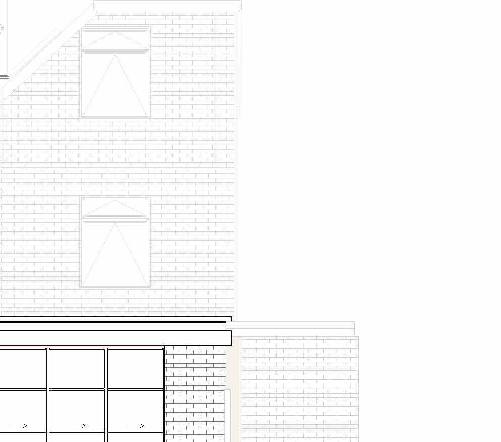
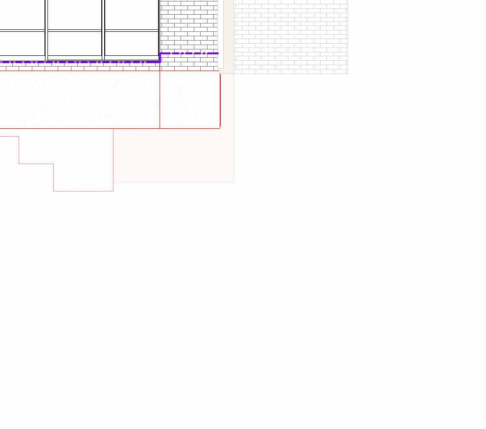
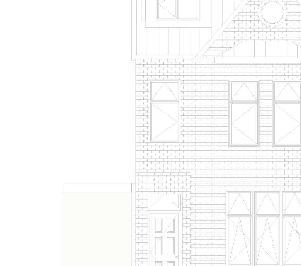
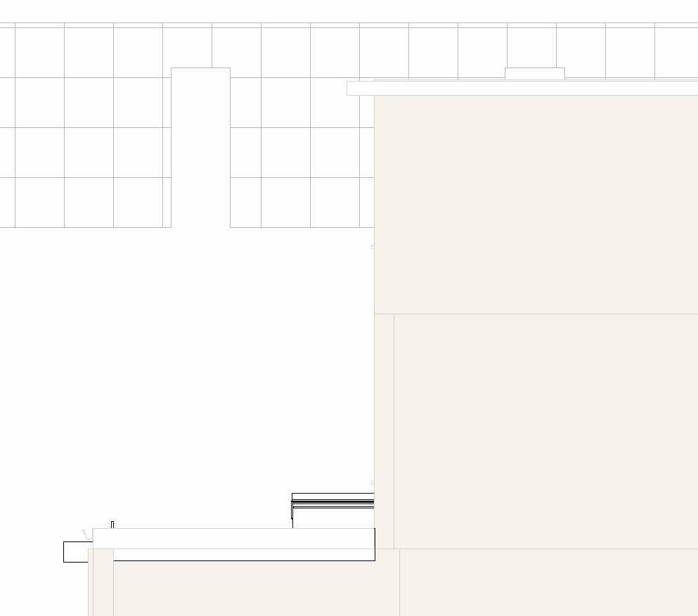
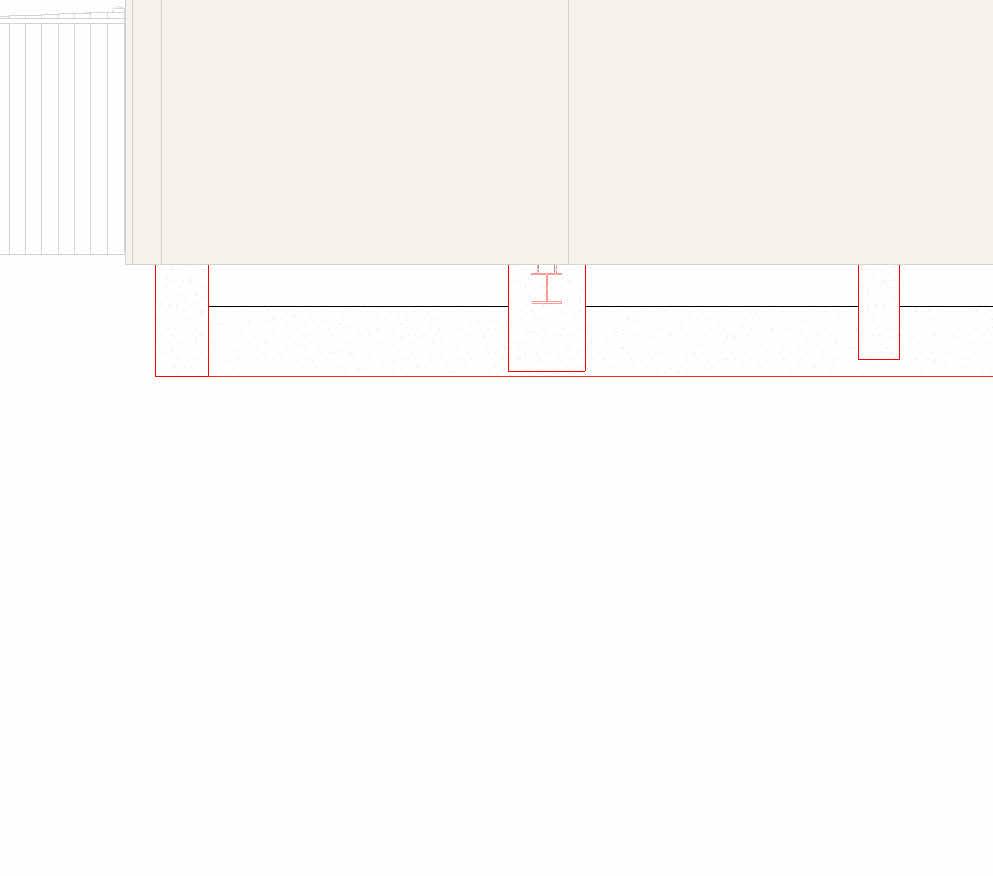
© THIS DRAWING IS THE COPYRIGHT OF DESIGNLABS LONDON LTD (DLL). It shall not be in any way used or reproduced or construct without their prior written consent. Al dimensions are to be checked on site by client or contractor prior to commencing any work. Work only to figured dimensions. Any discrepancies are to be reported to the DLL in writing and DLL shall not take responsiblity for site failing to inform discrepancies. Project : Drawing Scale Date : Rev Dwg No Status : ARCHITECTURE / INTERIOR / MANAGEMENT / PLANNING T: 07870661614 / 07888831314 E: info@designlabslondon.com W: www.designlabslondon.com DESIGNLABS LONDON As indicated 1 Setting-Out Elevations'Proposed Elevations 16 Priory Road, Richmond TW9 3DF NC-GR02-DR-YY-03511/10/2022 Const 1 : 50 Proposed Front Elevation1 1 : 50 Proposed Rear Elevation2 0 SCALE 1: 2.521.510.50.5 m50 W-03 TYPE 2
Notes:
Rafter Direction Rafter Size 150x50mm C24 @400 Centers
1. ALL DIMENSIONS IN MILLIMETERS UNLESS OTHERWISE SPECIFIED.


2. THE CONTRACTOR TO CHECK
DIMENSIONS, ANGLES, DRAIN RUNS AND CONDITIONS ON SITE BEFORE WORKS COMMENCEMENT. ANY DISCREPANCIES REPORT IMMEDIATELY TO THE ENGINEER.
3. CONDITION OF ALL EXISTING STRUCTURAL ELEMENTS, WITH PARTICULAR ATTENTION TO EXISTING BEARING WALLS TO BE USED FOR THE PROPOSED DEVELOPMENT, TO BE CHECKED BY THE CONTRACTOR BEFORE WORKS COMMENCEMENT.
4. DRAWINGS TO BE READ IN CONJUNCTION WITH RELATIVE STRUCTURAL CALCULATIONS, DETAILS AND SPECIFICATION. 5. DO NOT SCALE FROM DRAWINGS. DIMENSIONS ARE INDICATIVE ONLY.
6. CONTRACTOR AND CLIENT TO BE AWARE OF CONSTRUCTION & DESIGN MANAGEMENT (CDM) DUTIES.
Ground Floor 0 First Floor 3375 First Floor Mezzanine Level 5650 Roof Level 9155 Ground Floor Mezzanine Level 2815 Lower Ground Floor Level -1880 Loft Level 6690 0.1 Proposed Basement -3300 Concrete Foundation 650x900 Concrete Foundation 300 800mm Wall Foundation Bearing Footing1000x450mm Wall Foundation Bearing Footing1000x450mm EW30 26772658 247 3742 B0.02 UKC254x254x73 W-01 TypeWCRF01 SYMBOL LEGEND Denotes Span of block on beam floor at ground floor level. Wall Types Tag- See drawing for Wall Types Door Type & Number- See Door Schedule for futher details Window Type & Number- See Window Schedule for futher details Electrical Meter Incoming Water Mains VFS Vertical Fire Stops DFS Stepped Fire Stops (to follow roof line) Joist Direction Joist sizes 220x50mm C24 @400 centers Double/Triple Trimmers sizes 2x200x50mm C24 Bolted @600 centers LEGEND Roof Slope Direction in Decimal Degree
ALL
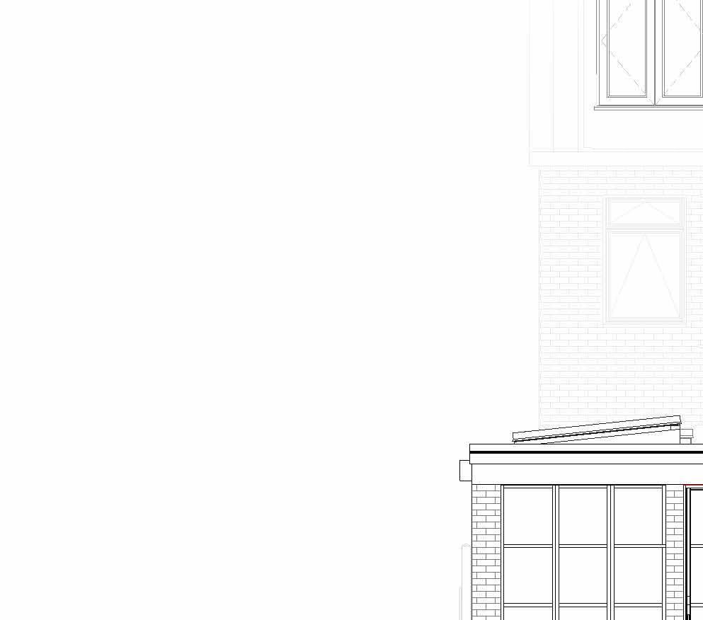
© THIS DRAWING IS THE COPYRIGHT OF DESIGNLABS LONDON LTD (DLL). It shall not be in any way used or reproduced or construct without their prior written consent. Al dimensions are to be checked on site by client or contractor prior to commencing any work. Work only to figured dimensions. Any discrepancies are to be reported to the DLL in writing and DLL shall not take responsiblity for site failing to inform discrepancies. Project : Drawing Scale Date : Rev Dwg No Status : ARCHITECTURE / INTERIOR / MANAGEMENT / PLANNING T: 07870661614 / 07888831314 E: info@designlabslondon.com W: www.designlabslondon.com DESIGNLABS LONDON As indicated Setting-Out Elevations'Proposed Elevations 16 Priory Road, Richmond TW9 3DF NC-GR02-DR-YY-03611/10/2022 Const 1 50 Proosed RHS Elevation 2 0 SCALE 1: 2.521.50.50.5 m50
Notes:
Rafter Direction Rafter Size 150x50mm C24 @400 Centers
THE

CONDITION OF
EXISTING STRUCTURAL ELEMENTS, WITH PARTICULAR ATTENTION TO EXISTING BEARING WALLS TO BE USED FOR THE PROPOSED DEVELOPMENT, TO BE CHECKED BY THE CONTRACTOR BEFORE WORKS COMMENCEMENT.
4. DRAWINGS TO BE READ IN CONJUNCTION WITH RELATIVE STRUCTURAL CALCULATIONS, DETAILS AND SPECIFICATION. 5. DO NOT SCALE FROM DRAWINGS. DIMENSIONS ARE INDICATIVE ONLY.
6. CONTRACTOR AND CLIENT TO BE AWARE OF CONSTRUCTION & DESIGN MANAGEMENT (CDM) DUTIES.
Ground Floor 0 First Floor 3375 First Floor Mezzanine Level 5650 Roof Level 9155 Ground Floor Mezzanine Level 2815 Lower Ground Floor Level -1880 Loft Level 6690 0.1 Proposed Basement -3300 Wall Foundation Bearing Footing1000x450mm Stepped Footing 247 2848 3545 985 218 985 218 985 2168 W-01 TypeWC EW-31 9104 DPC layer 300 W-02 TypeWC W-03 TypeWC W-04 TypeWB SYMBOL LEGEND Denotes Span of block on beam floor at ground floor level. Wall Types Tag- See drawing for Wall Types Door Type & Number- See Door Schedule for futher details Window Type & Number- See Window Schedule for futher details Electrical Meter Incoming Water Mains VFS Vertical Fire Stops DFS Stepped Fire Stops (to follow roof line) Joist Direction Joist sizes 220x50mm C24 @400 centers Double/Triple Trimmers sizes 2x200x50mm C24 Bolted @600 centers LEGEND Roof Slope Direction in Decimal Degree 1. ALL DIMENSIONS IN MILLIMETERS UNLESS OTHERWISE SPECIFIED. 2. THE CONTRACTOR TO CHECK ALL DIMENSIONS, ANGLES, DRAIN RUNS AND CONDITIONS ON SITE BEFORE WORKS COMMENCEMENT. ANY DISCREPANCIES REPORT IMMEDIATELY TO
ENGINEER. 3.
ALL
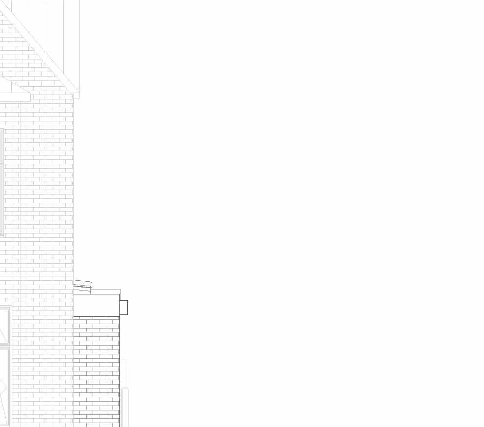
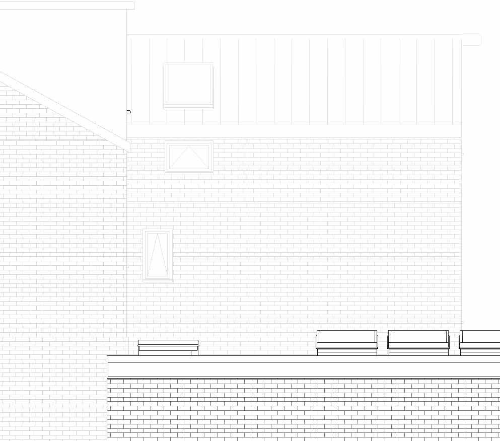
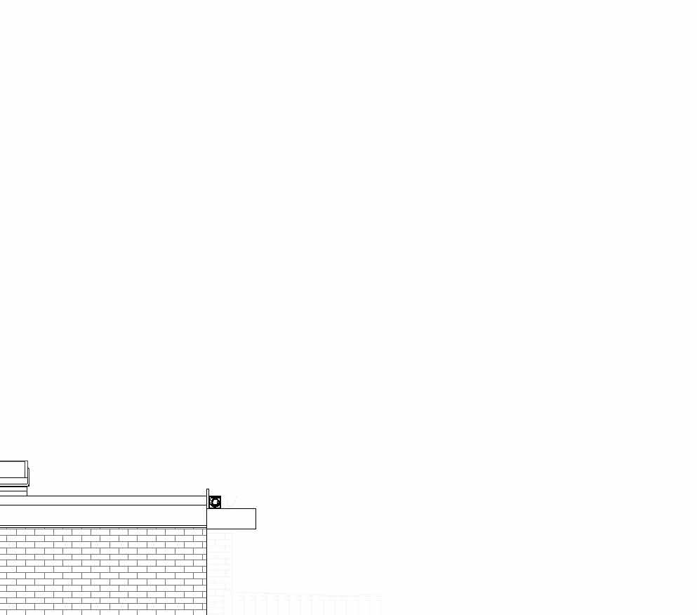
© THIS DRAWING IS THE COPYRIGHT OF DESIGNLABS LONDON LTD (DLL). It shall not be in any way used or reproduced or construct without their prior written consent. Al dimensions are to be checked on site by client or contractor prior to commencing any work. Work only to figured dimensions. Any discrepancies are to be reported to the DLL in writing and DLL shall not take responsiblity for site failing to inform discrepancies. Project : Drawing Scale Date : Rev Dwg No Status : ARCHITECTURE / INTERIOR / MANAGEMENT / PLANNING T: 07870661614 / 07888831314 E: info@designlabslondon.com W: www.designlabslondon.com DESIGNLABS LONDON As indicated Setting-Out Elevations'Proposed Elevations 16 Priory Road, Richmond TW9 3DF NC-GR02-DR-YY-03711/10/2022 Const 1 : 50 Proposed LHS Elevation1
Structural Drawing Set
© THIS DRAWING IS THE COPYRIGHT OF DESIGNLABS LONDON LTD (DLL). It shall not be in any way used or reproduced or construct without their prior written consent. Al dimensions are to be checked on site by client or contractor prior to commencing any work. Work only to figured dimensions. Any discrepancies are to be reported to the DLL in writing and DLL shall not take responsiblity for site failing to inform discrepancies. Project : Drawing Scale Date : Rev Dwg No Status : ARCHITECTURE / INTERIOR / MANAGEMENT / PLANNING T: 07870661614 / 07888831314 E: info@designlabslondon.com W: www.designlabslondon.com DESIGNLABS LONDON Title Sheet- Structural Drawing Sheets 16 Priory Road, Richmond TW9 3DF NC-GR0411/10/2022 Const
DN 1NC-GR04-DR-XX-045 1NC-GR04-DR-XX-046 3NC-GR04-DR-XX-045 1NC-GR02-DR-XX-034 1NC-GR02-DR-XX-032 1NC-GR02-DR-XX-032 1NC-GR02-DR-XX-031 2NC-GR02-DR-XX-032 21 E 3 C0.01 UKC203x203x46 C0.02 UKC203x203x60 B0.01UKC203x203x60 Concrete Foundation 300 x 800mm Concrete Foundation / 650x900 B0.02 /UKC254x254x73 C0.04 SHS100x100x6.3 C0.05 SHS100x100x6.3 Stepped Footing 2NC-GR04-DR-XX-046 2NC-GR04-DR-XX-046 A B D C0.03 160x80x10 5620 2986 154 814 4931 405 272 C B1C0.06 SHS100x100x6.3 C0.07 160x80x10 Joist Direction - Joist sizes 220x50mm C24 @400 centers Double/Triple Trimmers sizes 2x200x50mm C24 Bolted @600 centers LEGEND Roof Slope Direction in Decimal Degree 1. ALL DIMENSIONS IN MILLIMETERS UNLESS OTHERWISE SPECIFIED. 2. THE CONTRACTOR TO CHECK ALL DIMENSIONS, ANGLES, DRAIN RUNS AND CONDITIONS ON SITE BEFORE WORKS COMMENCEMENT. ANY DISCREPANCIES REPORT IMMEDIATELY TO THE ENGINEER. 3. CONDITION OF ALL EXISTING STRUCTURAL ELEMENTS, WITH PARTICULAR ATTENTION TO EXISTING BEARING WALLS TO BE USED FOR THE PROPOSED DEVELOPMENT, TO BE CHECKED BY THE CONTRACTOR BEFORE WORKS COMMENCEMENT. 4. DRAWINGS TO BE READ IN CONJUNCTION WITH RELATIVE STRUCTURAL CALCULATIONS, DETAILS AND SPECIFICATION. 5. DO NOT SCALE FROM DRAWINGS. DIMENSIONS ARE INDICATIVE ONLY. 6. CONTRACTOR AND CLIENT TO BE AWARE OF CONSTRUCTION & DESIGN MANAGEMENT (CDM) DUTIES. Notes: Rafter Direction - Rafter Size 150x50mm C24 @400 Centers SYMBOL LEGEND Denotes Span of block on beam floor at ground floor level. Wall Types Tag- See drawing for Wall Types Door Type & Number- See Door Schedule for futher details Window Type & Number- See Window Schedule for futher details Electrical Meter Incoming Water Mains VFS Vertical Fire Stops DFS Stepped Fire Stops (to follow roof line) © THIS DRAWING IS THE COPYRIGHT OF DESIGNLABS LONDON LTD (DLL). It shall not be in any way used or reproduced or construct without their prior written consent. Al dimensions are to be checked on site by client or contractor prior to commencing any work. Work only to figured dimensions. Any discrepancies are to be reported to the DLL in writing and DLL shall not take responsiblity for site failing to inform discrepancies. Project : Drawing Scale Date : Rev Dwg No Status : ARCHITECTURE / INTERIOR / MANAGEMENT / PLANNING T: 07870661614 / 07888831314 E: info@designlabslondon.com W: www.designlabslondon.com DESIGNLABS LONDON As indicated 1 Proposed Ground Floor Structure 16 Priory Road, Richmond TW9 3DF NC-GR04-DR-00-04011/10/2022 Const Proposed Steel Column Schedule Base Level Base Offset Top Level Mark Top Offset Type Length Type Comments Volume W Comments Ground Floor -305 Ground Floor Mezzanine Level C0.01 -25 UKC203x203x46 3095 0.02 m³ 0.0461 Ground Floor -305 Ground Floor Mezzanine Level C0.02 -25 UKC203x203x60 3095 0.02 m³ 0.06 Ground Floor -320 Ground Floor Mezzanine Level C0.03 -230 160x80x10 2905 0.01 m³ Ground Floor -240 Ground Floor Mezzanine Level C0.04 -170 SHS100x100x6.3 2885 0.01 m³ Ground Floor -240 Ground Floor Mezzanine Level C0.05 -170 SHS100x100x6.3 2885 0.01 m³ Ground Floor -240 Ground Floor Mezzanine Level C0.06 -170 SHS100x100x6.3 2885 0.01 m³ Ground Floor -320 Ground Floor Mezzanine Level C0.07 -230 160x80x10 2905 0.01 m³ Grand total: 7 Proposed Steel Beam Schedule Reference Level Mark Type Cut Length Volume Start Level Offset End Level Offset Comments Ground Floor B0.01 UKC203x203x60 4094 0.03 m³ -305 -305 Ground Floor B0.02 UKC254x254x73 6221 0.06 m³ -310 -310 Ground Floor Concrete Beam 450x600 610 0.30 m³ -240 -240 Ground Floor Concrete Beam 450x1560 600 0.40 m³ -240 -240 Ground Floor Concrete Beam 450x2035 1033 0.91 m³ -240 -240 Ground Floor Concrete Foundation 300 x 800mm 5987 1.68 m³ -240 -240 Ground Floor Concrete Foundation 650x900 6136 3.59 m³ -240 -240 First Floor B1.01 UKC203x203x60 3681 0.03 m³ -588 -588 First Floor B1.02 UKC203x203x86 5540 0.06 m³ -522 -522 First Floor B1.03 UKC254x254x107 6159 0.08 m³ -523 -523 First Floor B1.04 PFC150x75x18 2879 0.01 m³ -564 -564 First Floor B1.05 PFC150x75x18 6088 0.01 m³ -564 -564 First Floor B1.07 UKC152x152x23 2825 0.01 m³ -564 -564 First Floor Steel Plate 6x310 6280 0.01 m³ -714 -714 Grand total: 14 0 SCALE 1: 1000800600400200200 mm25
DN 1NC-GR04-DR-XX-045 1NC-GR04-DR-XX-046 3NC-GR04-DR-XX-045 3NC-GR04-DR-XX-045 1NC-GR02-DR-XX-034 1NC-GR02-DR-XX-032 1NC-GR02-DR-XX-032 1NC-GR02-DR-XX-031 2NC-GR02-DR-XX-032 2NC-GR02-DR-XX-032 21 E 3 B1.02 UKC203x203x86 B1.07 UKC152x152x23 B1.04 PFC150x75x18 B1.05PFC150x75x18 Steel Plate 6x310 C0.01 UKC203x203x46 C0.02 UKC203x203x60 B1.01UKC203x203x60 2NC-GR04-DR-XX-046 2NC-GR04-DR-XX-046 A B D C C0.05 SHS100x100x6.3 C0.03 160x80x10 B1 2x Trimmers 3x Trimmers 3x Trimmers 3x Trimmers 3x Trimmers Metal Post 60x60x08 Weld to PFC to support over hang Roof Joist Direction - Joist sizes 220x50mm C24 @400 centers Double/Triple Trimmers sizes 2x200x50mm C24 Bolted @600 centers LEGEND Roof Slope Direction in Decimal Degree 1. ALL DIMENSIONS IN MILLIMETERS UNLESS OTHERWISE SPECIFIED. 2. THE CONTRACTOR TO CHECK ALL DIMENSIONS, ANGLES, DRAIN RUNS AND CONDITIONS ON SITE BEFORE WORKS COMMENCEMENT. ANY DISCREPANCIES REPORT IMMEDIATELY TO THE ENGINEER. 3. CONDITION OF ALL EXISTING STRUCTURAL ELEMENTS, WITH PARTICULAR ATTENTION TO EXISTING BEARING WALLS TO BE USED FOR THE PROPOSED DEVELOPMENT, TO BE CHECKED BY THE CONTRACTOR BEFORE WORKS COMMENCEMENT. 4. DRAWINGS TO BE READ IN CONJUNCTION WITH RELATIVE STRUCTURAL CALCULATIONS, DETAILS AND SPECIFICATION. 5. DO NOT SCALE FROM DRAWINGS. DIMENSIONS ARE INDICATIVE ONLY. 6. CONTRACTOR AND CLIENT TO BE AWARE OF CONSTRUCTION & DESIGN MANAGEMENT (CDM) DUTIES. Notes: Rafter Direction - Rafter Size 150x50mm C24 @400 Centers SYMBOL LEGEND Denotes Span of block on beam floor at ground floor level. Wall Types Tag- See drawing for Wall Types Door Type & Number- See Door Schedule for futher details Window Type & Number- See Window Schedule for futher details Electrical Meter Incoming Water Mains VFS Vertical Fire Stops DFS Stepped Fire Stops (to follow roof line) © THIS DRAWING IS THE COPYRIGHT OF DESIGNLABS LONDON LTD (DLL). It shall not be in any way used or reproduced or construct without their prior written consent. Al dimensions are to be checked on site by client or contractor prior to commencing any work. Work only to figured dimensions. Any discrepancies are to be reported to the DLL in writing and DLL shall not take responsiblity for site failing to inform discrepancies. Project : Drawing Scale Date : Rev Dwg No Status : ARCHITECTURE / INTERIOR / MANAGEMENT / PLANNING T: 07870661614 / 07888831314 E: info@designlabslondon.com W: www.designlabslondon.com DESIGNLABS LONDON As indicated 1 Proposed First Floor Structure 16 Priory Road, Richmond TW9 3DF NC-GR04-DR-01-04111/10/2022 Const Proposed Steel Column Schedule Base Level Base Offset Top Level Mark Top Offset Type Length Type Comments Volume W Comments Ground Floor -305 Ground Floor Mezzanine Level C0.01 -25 UKC203x203x46 3095 0.02 m³ 0.0461 Ground Floor -305 Ground Floor Mezzanine Level C0.02 -25 UKC203x203x60 3095 0.02 m³ 0.06 Ground Floor -320 Ground Floor Mezzanine Level C0.03 -230 160x80x10 2905 0.01 m³ Ground Floor -240 Ground Floor Mezzanine Level C0.04 -170 SHS100x100x6.3 2885 0.01 m³ Ground Floor -240 Ground Floor Mezzanine Level C0.05 -170 SHS100x100x6.3 2885 0.01 m³ Ground Floor -240 Ground Floor Mezzanine Level C0.06 -170 SHS100x100x6.3 2885 0.01 m³ Ground Floor -320 Ground Floor Mezzanine Level C0.07 -230 160x80x10 2905 0.01 m³ Grand total: 7 Proposed Steel Beam Schedule Reference Level Mark Type Cut Length Volume Start Level Offset End Level Offset Comments Ground Floor B0.01 UKC203x203x60 4094 0.03 m³ -305 -305 Ground Floor B0.02 UKC254x254x73 6221 0.06 m³ -310 -310 Ground Floor Concrete Beam 450x600 610 0.30 m³ -240 -240 Ground Floor Concrete Beam 450x1560 600 0.40 m³ -240 -240 Ground Floor Concrete Beam 450x2035 1033 0.91 m³ -240 -240 Ground Floor Concrete Foundation 300 x 800mm 5987 1.68 m³ -240 -240 Ground Floor Concrete Foundation 650x900 6136 3.59 m³ -240 -240 First Floor B1.01 UKC203x203x60 3681 0.03 m³ -588 -588 First Floor B1.02 UKC203x203x86 5540 0.06 m³ -522 -522 First Floor B1.03 UKC254x254x107 6159 0.08 m³ -523 -523 First Floor B1.04 PFC150x75x18 2879 0.01 m³ -564 -564 First Floor B1.05 PFC150x75x18 6088 0.01 m³ -564 -564 First Floor B1.07 UKC152x152x23 2825 0.01 m³ -564 -564 First Floor Steel Plate 6x310 6280 0.01 m³ -714 -714 Grand total: 14 0 SCALE 1: 1000800600400200200 mm25
Ground Floor 0 First Floor 3375 First Floor Mezzanine Level 5650 Roof Level 9155 Ground Floor Mezzanine Level 2815 Basement Ceiling -240 Lower Ground Floor Level -1880 Loft Level 6690 Garden LVL -600 21 3 B1.03 UKC254x254x107 B1.05 PFC150x75x18 Steel Plate 6x310 Wall Foundation Bearing Footing1000x450mmConcrete Foundation 650x900 B0.02 UKC254x254x73 Concrete Foundation 300 x 800mm Stepped Footing 350 2316 650 2539 450 3753 240 800 240 900 190 1000 590 B1.04 PFC150x75x18 2655 6 150 C0.04 SHS100x100x6.3 C0.03 160x80x10 B1.04 PFC150x75x18 Metal Post 60x60x8 Weld PFC to support Overhang Roof Ground Floor 0 First Floor 3375 First Floor Mezzanine Level 5650 Roof Level 9155 Ground Floor Mezzanine Level 2815 Basement Ceiling -240 Lower Ground Floor Level -1880 Loft Level 6690 Garden LVL -600 0.1 Proposed Basement -3300 E Stepped Footing Wall Foundation Bearing Footing 1000x450mm B1.01 UKC203x203x60 B1.02 UKC203x203x86 C0.02 UKC203x203x60 C0.01 UKC203x203x46 A B DC 450 2036 610 600 1033 1695 475 475 485 250 590 1685 590 2578 1000 190 B1 © THIS DRAWING IS THE COPYRIGHT OF DESIGNLABS LONDON LTD (DLL). It shall not be in any way used or reproduced or construct without their prior written consent. Al dimensions are to be checked on site by client or contractor prior to commencing any work. Work only to figured dimensions. Any discrepancies are to be reported to the DLL in writing and DLL shall not take responsiblity for site failing to inform discrepancies. Project : Drawing Scale Date : Rev Dwg No Status : ARCHITECTURE / INTERIOR / MANAGEMENT / PLANNING T: 07870661614 / 07888831314 E: info@designlabslondon.com W: www.designlabslondon.com DESIGNLABS LONDON 1 50 1 Proposed Structural Sections 16 Priory Road, Richmond TW9 3DF NC-GR04-DR-XX-04511/10/2022 Const 1 : 50 Proposed Structural Section S11 1 : 50 Proposed Structural Section S33 0 SCALE 1: 2.521.510.50.5 m50 Proposed Steel Beam Schedule Reference Level Mark Type Cut Length Volume Start Level Offset End Level Offset Comments Ground Floor B0.01 UKC203x203x60 4094 0.03 m³ -305 -305 Ground Floor B0.02 UKC254x254x73 6221 0.06 m³ -310 -310 Ground Floor Concrete Beam 450x600 610 0.30 m³ -240 -240 Ground Floor Concrete Beam 450x1560 600 0.40 m³ -240 -240 Ground Floor Concrete Beam 450x2035 1033 0.91 m³ -240 -240 Ground Floor Concrete Foundation 300 x 800mm 5987 1.68 m³ -240 -240 Ground Floor Concrete Foundation 650x900 6136 3.59 m³ -240 -240 First Floor B1.01 UKC203x203x60 3681 0.03 m³ -588 -588 First Floor B1.02 UKC203x203x86 5540 0.06 m³ -522 -522 First Floor B1.03 UKC254x254x107 6159 0.08 m³ -523 -523 First Floor B1.04 PFC150x75x18 2879 0.01 m³ -564 -564 First Floor B1.05 PFC150x75x18 6088 0.01 m³ -564 -564 First Floor B1.07 UKC152x152x23 2825 0.01 m³ -564 -564 First Floor Steel Plate 6x310 6280 0.01 m³ -714 -714 Grand total: 14 Proposed Steel Column Schedule Base Level Base Offset Top Level Mark Top Offset Type Length Type Comments Volume W Comments Ground Floor -305 Ground Floor Mezzanine Level C0.01 -25 UKC203x203x46 3095 0.02 m³ 0.0461 Ground Floor -305 Ground Floor Mezzanine Level C0.02 -25 UKC203x203x60 3095 0.02 m³ 0.06 Ground Floor -320 Ground Floor Mezzanine Level C0.03 -230 160x80x10 2905 0.01 m³ Ground Floor -240 Ground Floor Mezzanine Level C0.04 -170 SHS100x100x6.3 2885 0.01 m³ Ground Floor -240 Ground Floor Mezzanine Level C0.05 -170 SHS100x100x6.3 2885 0.01 m³ Ground Floor -240 Ground Floor Mezzanine Level C0.06 -170 SHS100x100x6.3 2885 0.01 m³ Ground Floor -320 Ground Floor Mezzanine Level C0.07 -230 160x80x10 2905 0.01 m³ Grand total: 7
9155
5650
Floor 3375
Floor Mezzanine
2815
Ground Floor 0
Level 9155 Ground Floor Mezzanine Level 2815
First Floor Mezzanine Level 5650
First Floor 3375
PFC150x75x18
Plate 6x310
C0.05 SHS100x100x6.3 C0.04 SHS100x100x6.3
Ground Floor 0
Ceiling -240
Level 6690 Garden LVL -600
Wall Foundation Bearing Footing 1000x450mm
Ground Floor Level -1880
C0.06 SHS100x100x6.3
First
First Floor Mezzanine Level
Roof Level
Ground
Level
Basement Ceiling -240 Lower Ground Floor Level -1880 Loft Level 6690 Garden LVL -600 2 13 B1.05 PFC150x75x18 Steel Plate 6x310 B1.03 UKC254x254x107 Wall Foundation Bearing Footing 1000x450mm Wall Foundation Bearing Footing1000x450mm Concrete Foundation 650x900 Concrete Foundation 300 800mm B0.01 UKC203x203x60B0.02 UKC254x254x73 B1.01 UKC203x203x60 Stepped Footing C0.07 160x80x10
Roof
Basement
Lower
Loft
E
B1.05
Steel
A B DCB1
© THIS DRAWING IS THE COPYRIGHT OF DESIGNLABS LONDON LTD (DLL). It shall not be in any way used or reproduced or construct without their prior written consent. Al dimensions are to be checked on site by client or contractor prior to commencing any work. Work only to figured dimensions. Any discrepancies are to be reported to the DLL in writing and DLL shall not take responsiblity for site failing to inform discrepancies. Project : Drawing Scale Date : Rev Dwg No Status : ARCHITECTURE / INTERIOR / MANAGEMENT / PLANNING T: 07870661614 / 07888831314 E: info@designlabslondon.com W: www.designlabslondon.com DESIGNLABS LONDON 1 50 1 Proposed Structural Sections 16 Priory Road, Richmond TW9 3DF NC-GR04-DR-XX-04611/10/2022 Const 1 : 50 Proposed Structural Section S21 1 50 Proposed Section C22 Proposed Steel Beam Schedule Reference Level Mark Type Cut Length Volume Start Level Offset End Level Offset Comments Ground Floor B0.01 UKC203x203x60 4094 0.03 m³ -305 -305 Ground Floor B0.02 UKC254x254x73 6221 0.06 m³ -310 -310 Ground Floor Concrete Beam 450x600 610 0.30 m³ -240 -240 Ground Floor Concrete Beam 450x1560 600 0.40 m³ -240 -240 Ground Floor Concrete Beam 450x2035 1033 0.91 m³ -240 -240 Ground Floor Concrete Foundation 300 x 800mm 5987 1.68 m³ -240 -240 Ground Floor Concrete Foundation 650x900 6136 3.59 m³ -240 -240 First Floor B1.01 UKC203x203x60 3681 0.03 m³ -588 -588 First Floor B1.02 UKC203x203x86 5540 0.06 m³ -522 -522 First Floor B1.03 UKC254x254x107 6159 0.08 m³ -523 -523 First Floor B1.04 PFC150x75x18 2879 0.01 m³ -564 -564 First Floor B1.05 PFC150x75x18 6088 0.01 m³ -564 -564 First Floor B1.07 UKC152x152x23 2825 0.01 m³ -564 -564 First Floor Steel Plate 6x310 6280 0.01 m³ -714 -714 Grand total: 14 Proposed Steel Column Schedule Base Level Base Offset Top Level Mark Top Offset Type Length Type Comments Volume W Comments Ground Floor -305 Ground Floor Mezzanine Level C0.01 -25 UKC203x203x46 3095 0.02 m³ 0.0461 Ground Floor -305 Ground Floor Mezzanine Level C0.02 -25 UKC203x203x60 3095 0.02 m³ 0.06 Ground Floor -320 Ground Floor Mezzanine Level C0.03 -230 160x80x10 2905 0.01 m³ Ground Floor -240 Ground Floor Mezzanine Level C0.04 -170 SHS100x100x6.3 2885 0.01 m³ Ground Floor -240 Ground Floor Mezzanine Level C0.05 -170 SHS100x100x6.3 2885 0.01 m³ Ground Floor -240 Ground Floor Mezzanine Level C0.06 -170 SHS100x100x6.3 2885 0.01 m³ Ground Floor -320 Ground Floor Mezzanine Level C0.07 -230 160x80x10 2905 0.01 m³ Grand total: 7 0 SCALE 1: 2.521.510.50.5 m50 Metal Post 60x60x8 Weld to PFC to support overhang Roof


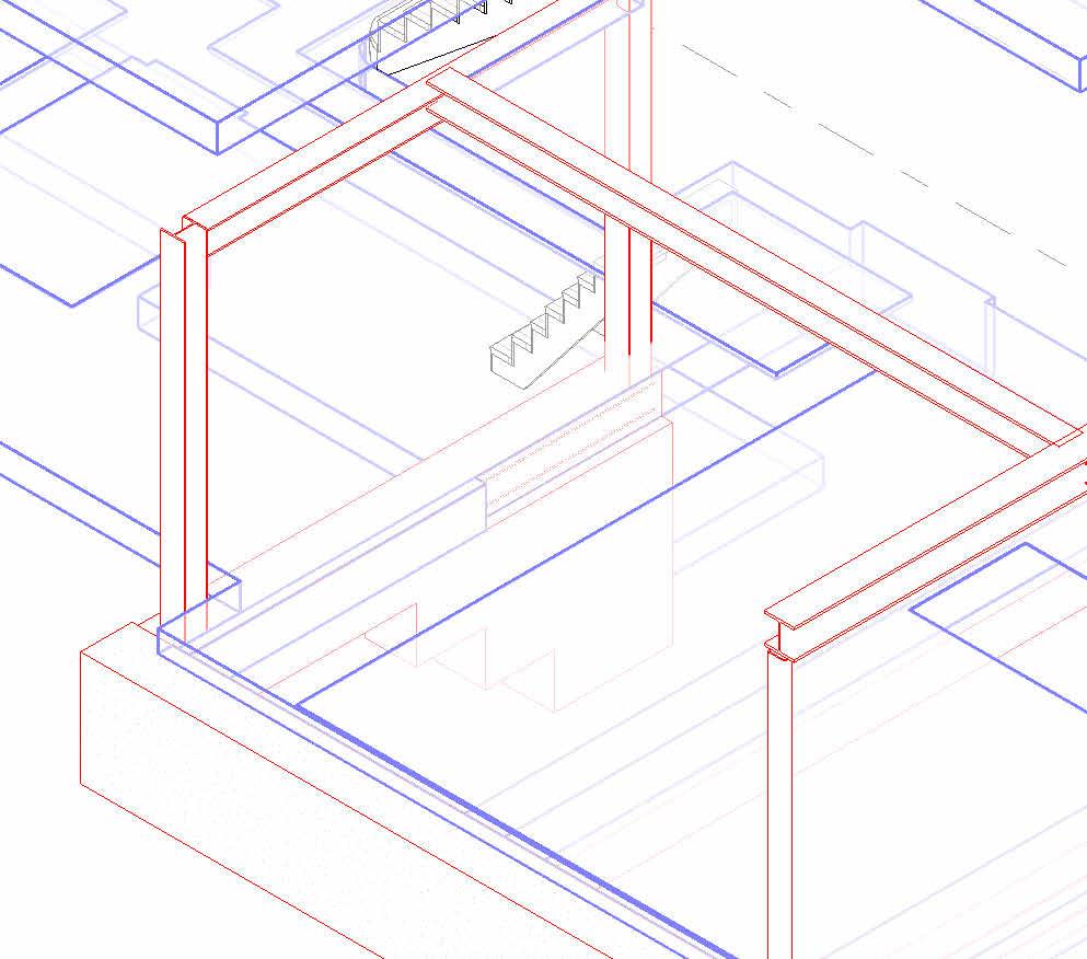
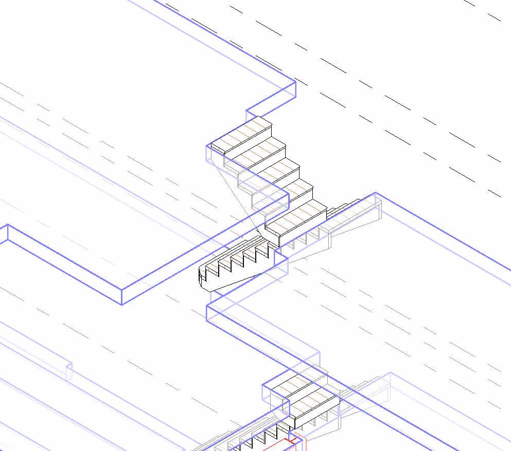

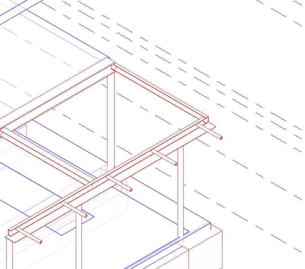

Wall Foundation Bearing Footing1000x450mm Wall Foundation Bearing Footing 1000x450mm Wall Foundation Bearing Footing 600x450mm Concrete Foundation 300 800mm ConcreteFoundation /650x900 B0.02/ UKC254x254x73 C0.05 SHS100x100x6.3 C0.04 SHS100x100x6.3 C0.02 UKC203x203x60 B1.01/ UKC203x203x60 C0.01 UKC203x203x46 B1.02/ UKC203x203x86 B1.03/ UKC254x254x107 B1.04/ PFC150x75x18 B1.05/ PFC150x75x18 C0.06 SHS100x100x6.3 C0.03 160x80x10 Steel Dowel 60x60x8 SHS to support overhang Roof C0.07 160x80x10 © THIS DRAWING IS THE COPYRIGHT OF DESIGNLABS LONDON LTD (DLL). It shall not be in any way used or reproduced or construct without their prior written consent. Al dimensions are to be checked on site by client or contractor prior to commencing any work. Work only to figured dimensions. Any discrepancies are to be reported to the DLL in writing and DLL shall not take responsiblity for site failing to inform discrepancies. Project : Drawing Scale Date : Rev Dwg No Status : ARCHITECTURE / INTERIOR / MANAGEMENT / PLANNING T: 07870661614 / 07888831314 E: info@designlabslondon.com W: www.designlabslondon.com DESIGNLABS LONDON 2 Structural 3Ds 16 Priory Road, Richmond TW9 3DF NC-GR04-DR-ZZ-04711/10/2022 Const Structural Isometrics 1 1
C0.04
B1.04/ PFC150x75x18
B1.07/ UKC152x152x23
B1.05/ PFC150x75x18
C0.01
B1.01/ UKC203x203x60
B1.02/ UKC203x203x86
C0.02


B0.02/


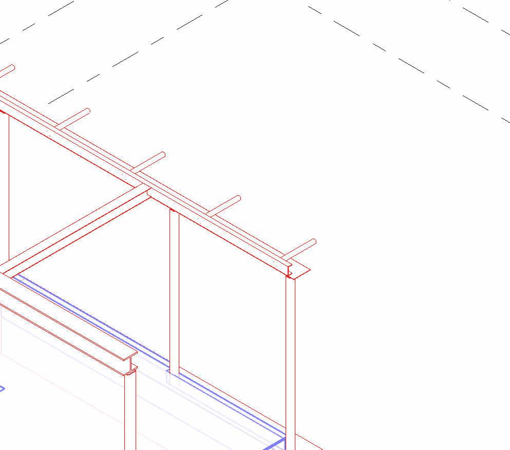

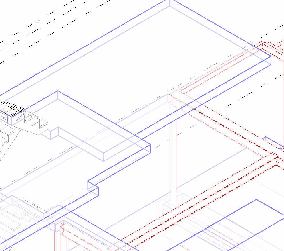
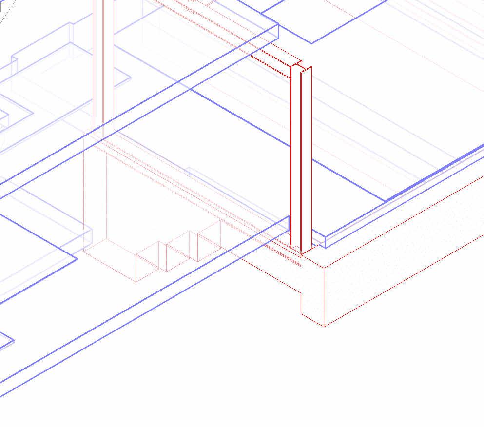

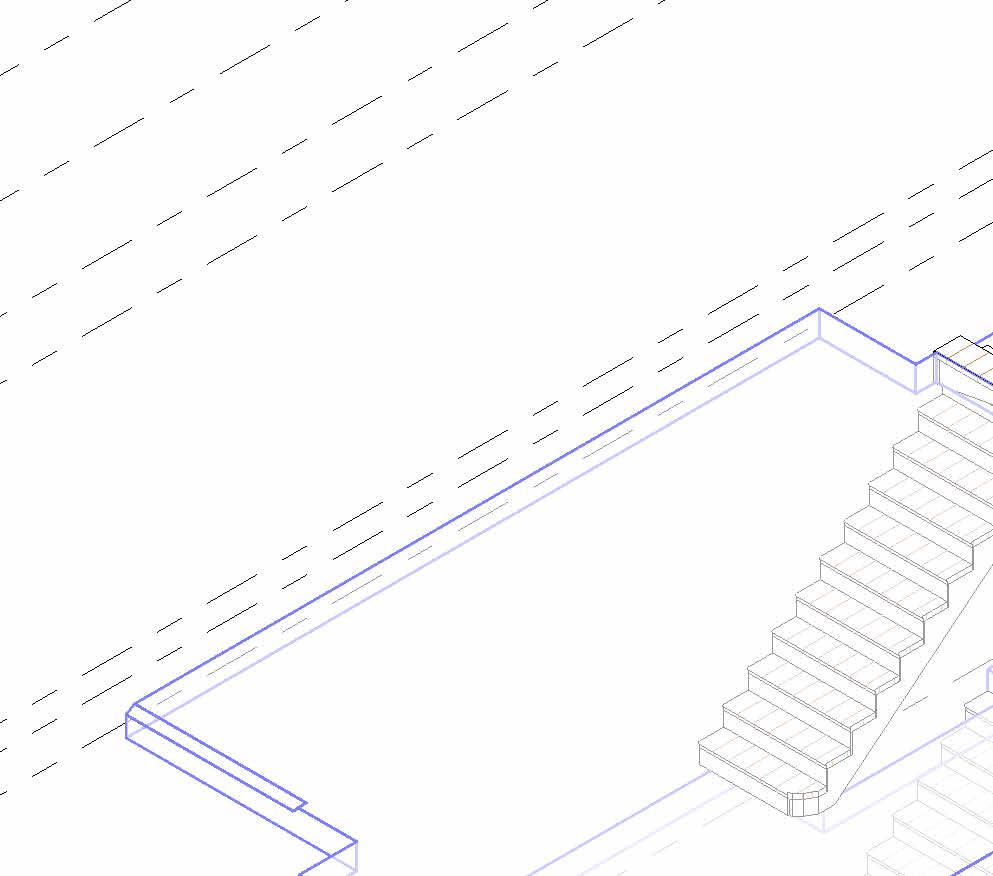
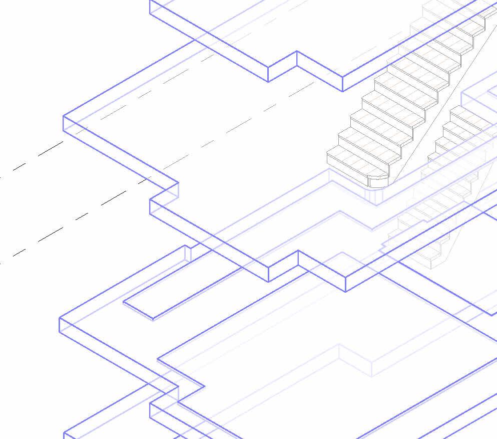


C0.06
C0.05 SHS100x100x6.3
C0.07
SHS100x100x6.3
UKC203x203x60
UKC203x203x46 Wall Foundation Bearing Footing 1000x450mm Sepped Footing B0.01/ UKC203x203x60 ConcreteFoundation /650x900
UKC254x254x73 Wall Foundation Bearing Footing1000x450mm SteelPlate/6x310
SHS100x100x6.3 B1.03/ UKC254x254x107 Dowels SHS60x60x8
160x80x10 © THIS DRAWING IS THE COPYRIGHT OF DESIGNLABS LONDON LTD (DLL). It shall not be in any way used or reproduced or construct without their prior written consent. Al dimensions are to be checked on site by client or contractor prior to commencing any work. Work only to figured dimensions. Any discrepancies are to be reported to the DLL in writing and DLL shall not take responsiblity for site failing to inform discrepancies. Project : Drawing Scale Date : Rev Dwg No Status : ARCHITECTURE / INTERIOR / MANAGEMENT / PLANNING T: 07870661614 / 07888831314 E: info@designlabslondon.com W: www.designlabslondon.com DESIGNLABS LONDON 2 Structural 3Ds 16 Priory Road, Richmond TW9 3DF NC-GR04-DR-ZZ-04811/10/2022 Const
© THIS DRAWING IS THE COPYRIGHT OF DESIGNLABS LONDON LTD (DLL). It shall not be in any way used or reproduced or construct without their prior written consent. Al dimensions are to be checked on site by client or contractor prior to commencing any work. Work only to figured dimensions. Any discrepancies are to be reported to the DLL in writing and DLL shall not take responsiblity for site failing to inform discrepancies. Project : Drawing Scale Date : Rev Dwg No Status : ARCHITECTURE / INTERIOR / MANAGEMENT / PLANNING T: 07870661614 / 07888831314 E: info@designlabslondon.com W: www.designlabslondon.com DESIGNLABS LONDON Title Sheet- Building Elements Types and Schedule 16 Priory Road, Richmond TW9 3DF NC-GR0511/10/2022 Const Building Elements Type Legends and Schedules (Wall, Roofs, Floors, Door & Window Type Schedules)
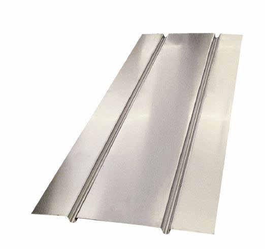
DN Kitchen + Dining G5 Cinema/Media Room G6 WC G4 Living Room G2 Entrance Hall G1 Coats G3 UFH2UFH1 UFH3 UFH4 UFH6 UFH6 UFH Zone 1 9.058 Sqm. UFH Zone 2 16.69 Sqm. UFH Zone 3 3.39 Sqm. UFH Zone 4 1.7 Sqm. UFH Zone 6 9.554Sqm. UFH Zone 5 34.672 Sqm. UFH Zone 6 3.562 Sqm. UFH Zone 1 1.170 Sqm. Concrete Under Floor Heating Timber Under Floor Heating facing brickwork existing wall damp proof course (assumed) ventilation to void provided by ventilation sleeves at intervals sloped to external face of wall existing wall 6mm parge coat -377 FFL 150mm min Perimeter strip of insulation abuts joist and masonry wall. Void below suspended floor is ventilated, using air bricks and connection sleeves at intervals. Min 150mm ventilation void area. Joists design according to individual project requirements and TRADA span tables. SUSPENDED TIMBER FLOOR assumed existing foundation concrete blinded over damp proof membrane on compacted hardcore timber joists supported by joist hangers Insulation between joists John Guest or similar Metal Spreader Plates for the underfloor heating pipes to floor joists over vapour control layer 9mm dot and dab layer perimeter insulation to joists to prevent thermal bridging 12.5mm plasterboard and skim finish 0 FFL 150mm min 240 102 10 102 18mm plywood for floor finishes. 232 377 232 heating pipe below plywood PIR Insulation between joists- insulation edge tape around using Gapotape to seal all edges and maximise insulation efficiency © THIS DRAWING IS THE COPYRIGHT OF DESIGNLABS LONDON LTD (DLL). It shall not be in any way used or reproduced or construct without their prior written consent. Al dimensions are to be checked on site by client or contractor prior to commencing any work. Work only to figured dimensions. Any discrepancies are to be reported to the DLL in writing and DLL shall not take responsiblity for site failing to inform discrepancies. Project : Drawing Scale Date : Rev Dwg No Status : ARCHITECTURE / INTERIOR / MANAGEMENT / PLANNING T: 07870661614 / 07888831314 E: info@designlabslondon.com W: www.designlabslondon.com DESIGNLABS LONDON As indicated Under Floor Heating Schedule Page 1 of 2 16 Priory Road, Richmond TW9 3DF NC-GR05-SC-00-05111/10/2022 Const 1 : 50 GA-Proposed Ground Floor Plan1 Kitchen Island Void Kitchen Island Void Furniture Void Staircase Void Compony Product Code Discription Size johnguest JGUFHSP400 JGUnderfloor Spreader Plates 390x1000 mm
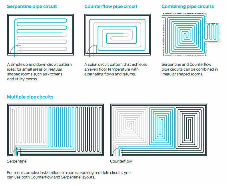
© THIS DRAWING IS THE COPYRIGHT OF DESIGNLABS LONDON LTD (DLL). It shall not be in any way used or reproduced or construct without their prior written consent. Al dimensions are to be checked on site by client or contractor prior to commencing any work. Work only to figured dimensions. Any discrepancies are to be reported to the DLL in writing and DLL shall not take responsiblity for site failing to inform discrepancies. Project : Drawing Scale Date : Rev Dwg No Status : ARCHITECTURE / INTERIOR / MANAGEMENT / PLANNING T: 07870661614 / 07888831314 E: info@designlabslondon.com W: www.designlabslondon.com DESIGNLABS LONDON Under Floor Heating Schedule Page 2 OF 2 16 Priory Road, Richmond TW9 3DF NC-GR05-SC-00-05211/10/2022 Const Piping circuit Layout USE COUNTERFLOOR PIPE CIRCUIT OF THIS PROJECT WHERE POSSIBLE (SMALLER SPACES) USE MULTIPLE CIRCUITS IN LARGER ROOMS
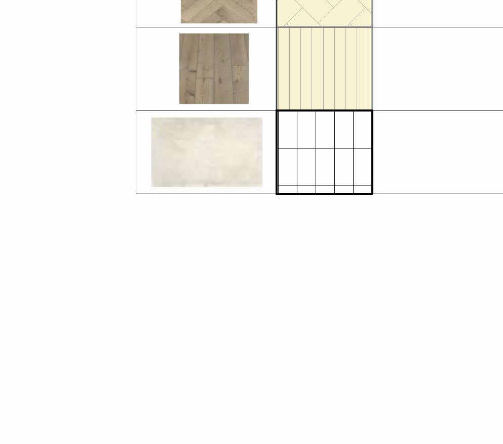
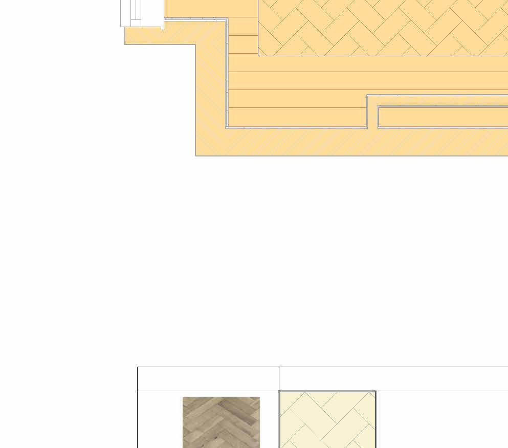
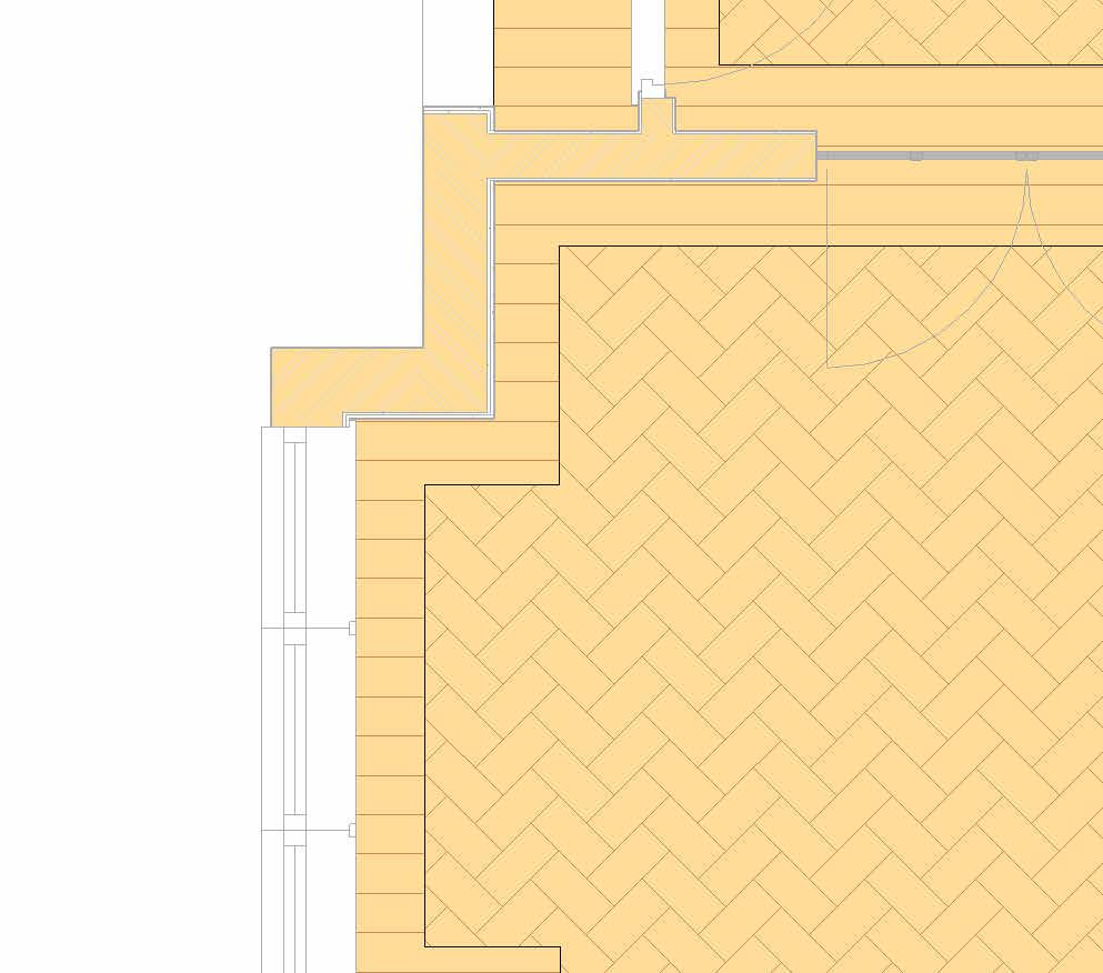
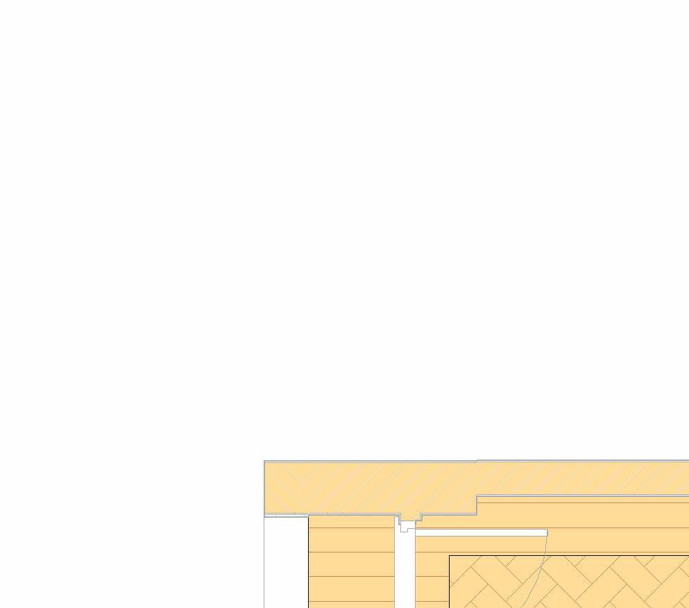

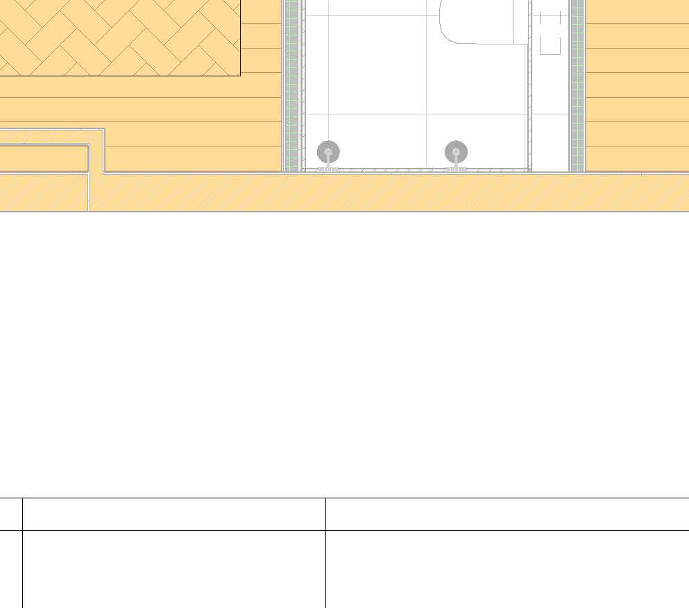
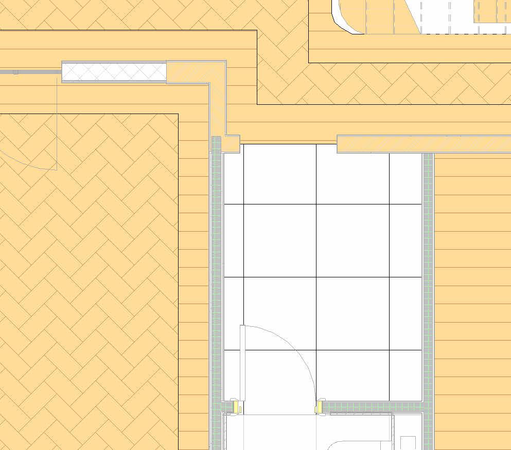

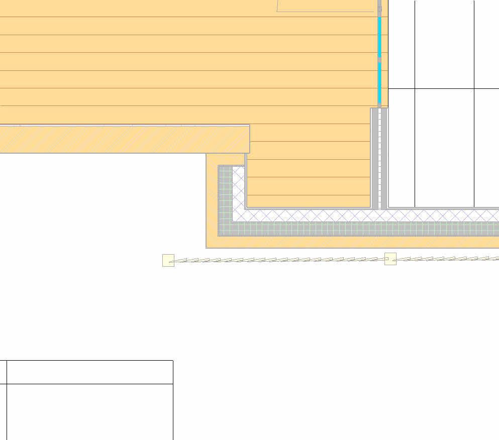
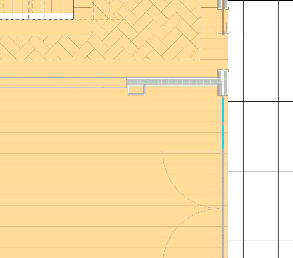
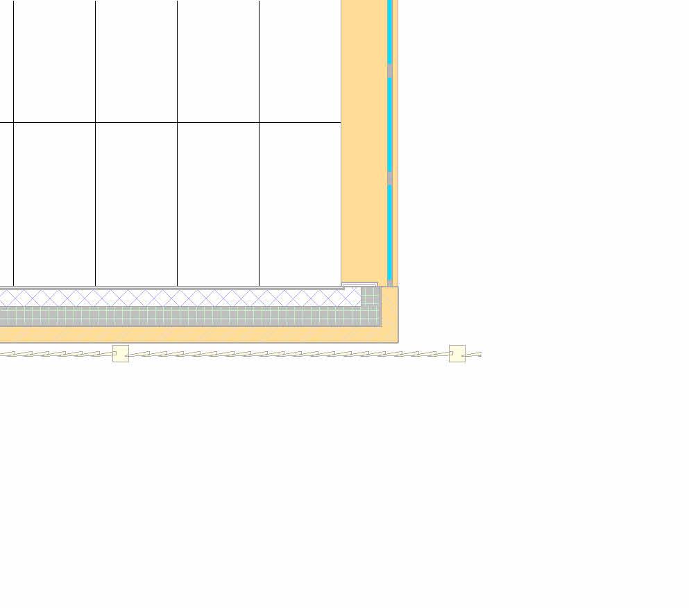
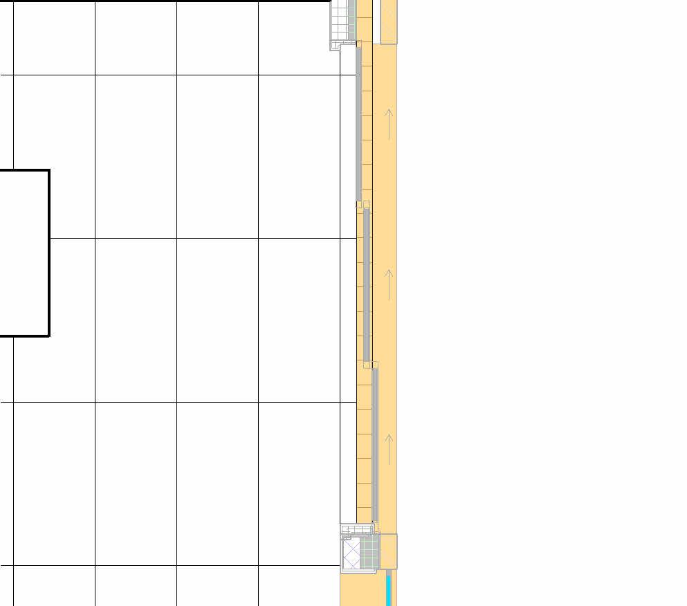
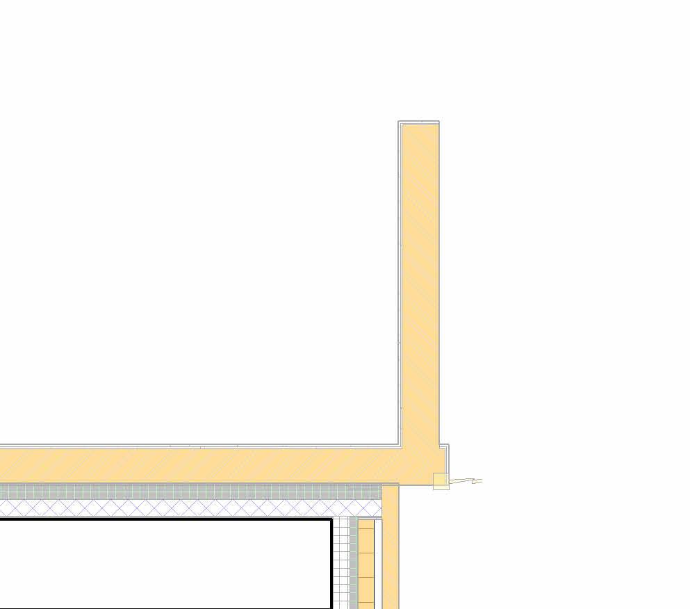
Area of Tile Floor 38 Sq m. 14 m² Cinema/Media Room G6 Kitchen + Dining G5 3 m² Coats G3 17 m² Living Room G2 13 m² Entrance Hall G1 WC G4 5505 7222 3905 3499 1020 698 1380 1360 Kitchen Void Kitchen Island Void Wood Flooring Wood Flooring 1000x500x11mm Tile Floor Legend Item Entrance Hall, Drawing Room Snug & all Bedroom Kitchen Description Small Herringbone Tongue and Grove 90x14/3x400mm with single plank boarder Bespoke Woodflooring iron 190x14/3x1900mm Rustic Grade Brush & UV Oiled Click System Aubergine Blanco Porcelain 1000x500x11mm Floor Legend Area Of Floor 38 Sq m. 28 Sq m. 18 Sq m. Notes: - Sub-floor or Substrate to be free of debris and leveled evenly before floor finishes applied. - Client /Contractor to double check if floor finishes are suitable for underfloor heating. © THIS DRAWING IS THE COPYRIGHT OF DESIGNLABS LONDON LTD (DLL). It shall not be in any way used or reproduced or construct without their prior written consent. Al dimensions are to be checked on site by client or contractor prior to commencing any work. Work only to figured dimensions. Any discrepancies are to be reported to the DLL in writing and DLL shall not take responsiblity for site failing to inform discrepancies. Project : Drawing Scale Date : Rev Dwg No Status : ARCHITECTURE / INTERIOR / MANAGEMENT / PLANNING T: 07870661614 / 07888831314 E: info@designlabslondon.com W: www.designlabslondon.com DESIGNLABS LONDON As indicated Ground Floor- Flooring Plan and Schedule 16 Priory Road, Richmond TW9 3DF NC-GR05-SC-00-05511/10/2022 Const
Exterior Wall Type Legend
DescriptionNo Cross-Section
New House External Cavity Wall (U-Value 0.14 W/m2k)
External to Internal Finish:
EXW-31
- 100mm Brick Work over, - 10mm Matching cavity over - 115mm Kingspan Kooltherm K106 Insulation, - 100mm block 7kN Concrete masonry blockwork over, - 8mm Adhesive Layer over, - 12.5 Plasterboard skimmed finished
Interior Wall Type Legend
DescriptionNo Cross-Section
IW-12
New Internal Stud Partition Wall -125mm ThickExternal to Internal Finish: 2x12.5 mm Plasterboard; 75mm Tanalised S/w Timber Studs @600mm c/c Filled with 50mm Isover APR 1200 Acoustical Insulation, 2x12.5 mm Plasterboard./ MR Plasterboard in Bathroom Area
IW-11
EXW-30
New House External Party Wall (U-Value 0.18 W/m2k)
External to Internal Finish:
- 100mm Celotex GA 4100 Insulation in 100mm cavity, - 100mm block 7kN Concrete masonry blockwork over, - 8mm Adhesive Layer over, - 12.5mm Plasterboard skimmed finished
New House External Brick Wall (U-Value N.A) External to Internal Finish:
EXW-03
- 100mm Matching Brick Work
IW-13C
New Internal Stud Partition Wall- 100 mm thick External to Internal Finish: 12.5 mm Plasterboard; 75mm Tanalised S/w Timber Studs @600mm c/c c/c Filled with 50mm Isover APR 1200 Acoustical Insulation, 12.5 mm Plasterboard./ MR Plasterboard in Bathroom Area
New Internal Stud Partition Wall with Pocket for door- 185mm thick External to Internal Finish: - 12.5 mm Plasterboard; - 50mm Metal Stud layer over, or 50x75 Tanalised S/w Timber Stud over @ 600mm c/c, - 50mm Isover APR 1200 sound insulation over,(Or Pocket for Door) - 50mm Metal Stud layer over, or 50x75 Tanalised S/w Timber Stud over@600mm c/c, - 12.5 mm Plasterboard
IW-9
IW-21 IW-20
New Internal Stud Partition Wall- 190mm thick External to Internal Finish: - 12.5 mm Gypsum wall board, - 8mm Adhesive Layer over, - 140mm Concrete Masonry Block Work over, - 8mm Adhesive Layer over, - 12.5 mm Gypsum wall board,
New Internal Stud Lining - 163mm
- 12.5
100mm
-50mm
GA 4100 PIR
stud
New Insulated Plasterboard Wall- 72.5mm
- 12.5
60mm
Brether
Gypsum
thick External to Internal Finish:
mm Gypsum wall board, -
Celotex
insulation over,
Memberane over,
Metal
layer
thick External to Internal Finish:
mm
wall board, -
insulation Floor Type Legend No Diagram Roof Type Legend RF.01 Flat roof No Diagram New Roof over G.F. Rear Extension- U-Value 0.15 5mm Water Proofing over 12mm Plywood Sheathing OSB Board over 140mm Kingspan TR 26 Insulation over Breather memberane over 18mm WBP Plywood Sheathing over 25mm to 50mm Variable height firrings over 175x50mm C16 Timber Joist @ 400 mm c/c FL01 Mainhouse: Concrete Ground Bearing Slab New House- Ground Level Insulated Floor 15mm Timber or tile Flooring over, 75mm Screed with heating pipes over, 100mm Kingspan Insulation over, 2000mm guage polyethene DPM membrane over, 200mm Concrete Slab with Reinforcement over, 50mm Sand Cement Binding Layer over, 150mm Type A Site Hardcore © THIS DRAWING IS THE COPYRIGHT OF DESIGNLABS LONDON LTD (DLL). It shall not be in any way used or reproduced or construct without their prior written consent. Al dimensions are to be checked on site by client or contractor prior to commencing any work. Work only to figured dimensions. Any discrepancies are to be reported to the DLL in writing and DLL shall not take responsiblity for site failing to inform discrepancies. Project : Drawing Scale Date : Rev Dwg No Status : ARCHITECTURE / INTERIOR / MANAGEMENT / PLANNING T: 07870661614 / 07888831314 E: info@designlabslondon.com W: www.designlabslondon.com DESIGNLABS LONDON 1 20 Schedule- Wall, Floor and Roof Schedule 16 Priory Road, Richmond TW9 3DF NC-GR05-SC-SC-05611/10/2022 Const
Denotes opening lines - Refer to window schedule & elevations for hanging. Skylights to be in powder coated finish extrnally in RAL 7016 and internally in RAL 9010 Client to confirm. All window frames to be in Hardwood and finished Externally n satin RAL 9010 as manufacturers details. Internally Window frames to be finished in RAL 9010 Client to confirm. Ironmongery to be proposed by manufacturer. Denotes 'Toughened Glazing'T Structural OpeningS/O Fixed Glass PaneFIXED Ground floor FFL SkylightInternal FIXED Glazing External Dim 1540 External Dim 2040 1 Nos. 3 Nos. TYPE WB TYPE WC Fixed Glazing External Dim 1040 External Dim 1040 Electrically (Switch) Openable 1000 x 1500mm skylight from Signature Electrically (Switch) openable 2000 x 1000mm skylight from Signature FORINTERNAL GLAZING-SEE DOORSHEDULE 1976 2170 3 40 670 40 670 40 670 40 40 578 40 40 579 40 40 579 40 EXTERNAL GLAZING Crittall Style Rear Side hung Casement Windows. Double/Triple Glazed U-Value: 1.4 W/m2K © THIS DRAWING IS THE COPYRIGHT OF DESIGNLABS LONDON LTD (DLL). It shall not be in any way used or reproduced or construct without their prior written consent. Al dimensions are to be checked on site by client or contractor prior to commencing any work. Work only to figured dimensions. Any discrepancies are to be reported to the DLL in writing and DLL shall not take responsiblity for site failing to inform discrepancies. Project : Drawing Scale Date : Rev Dwg No Status : ARCHITECTURE / INTERIOR / MANAGEMENT / PLANNING T: 07870661614 / 07888831314 E: info@designlabslondon.com W: www.designlabslondon.com DESIGNLABS LONDON As indicated 2 Window Schedule 16 Priory Road, Richmond TW9 3DF NC-GR05-SC-SC-05711/10/2022 Const Window Type Schedule Window No. Mark Width Height Sill Height Head Height Description & Operation Sidehung Tophung Window - Tilt & Turn Window Cleaning Comments W-03 TypeWC 985 1985 Fixed Flat Roof Skylight Yes Terrace Signature Skylight W-04 TypeWB 985 1485 Fixed Flat Roof Skylight Yes Terrace Signature Skylight
Ground floor FFL First PROPOSED INTERNAL DOORs Type G1 Single Swing Door Type E Pocket Door Type G Single Swing Door 2040 626 726 2040 926 2090 450 1400 1700 Loft Level PROPOSED EXTERNAL DOORs Type R 1100 Laminated clear glass balustrade to inside. Doors to open outside. Appox. 100mm stiles. External threshold Ground Floor 0 810 1630 810 40 345 40 345 40 3 40 345 40 345 40 3 40 345 40 345 40 4 40 345 40 345 40 2135 904 203 Crittall Style Double Door with Fixed Glazing Panes On Either Sides Type B Ground Floor 0 DG.05 Type Q 2658 4 EW-31 DPC 4035 19 94 411 40 670 40 670 40 650 20 42 30 41 944 40 942 40 943 40 External Rear Sliding Door With Pocket Type Q Ground Floor 0 Ground Floor Mezzanine Level 2815 740 2380 1600 40 320 40 360 80 360 40 320 40 660 40 40 740 40 740 40 740 40 40 Crittall Style Double Door with Fixed Glazing Panes Above Type B1 © THIS DRAWING IS THE COPYRIGHT OF DESIGNLABS LONDON LTD (DLL). It shall not be in any way used or reproduced or construct without their prior written consent. Al dimensions are to be checked on site by client or contractor prior to commencing any work. Work only to figured dimensions. Any discrepancies are to be reported to the DLL in writing and DLL shall not take responsiblity for site failing to inform discrepancies. Project : Drawing Scale Date : Rev Dwg No Status : ARCHITECTURE / INTERIOR / MANAGEMENT / PLANNING T: 07870661614 / 07888831314 E: info@designlabslondon.com W: www.designlabslondon.com DESIGNLABS LONDON 1 20 2 Door Schedule 16 Priory Road, Richmond TW9 3DF NC-GR05-SC-SC-05811/10/2022 Const 16 Priory Road- Door Schedule LOCATION DOOR REFERENCE STRUCTU RAL OPENING DOOR LEAF & DESCRIPTION FIRE NOTES Count Level Door Ref. Room Location Door Type Width (mm) Height (mm) Door Panel Height Door Panel Width Door Panel Thickness Single or Double Handing Vision Panel/Glazing Fire Rating Intumescent Seals Smoke Seals Self Closing Electronic Hold Open Notes / Comments Ground Floor Ground Floor DG.01 Kitchen + Dining Type E 876 2100 Sliding Pocket Door with Glazing N/A ● FD30 ● ● 1 Ground Floor DG.02 Entrance Hall Type B1 1520 2340 Double Door Single Swing See Drawings ● FD30 ● ● Double Door with Fixed Glazing Panes Above. Thickness & Pane Size to Specialist Design 1 Ground Floor DG.04 WC Type G1 736 2105 2040 626 44 Single Swing Door See Drawings 1 Ground Floor DG.05 Kitchen + Dining Type Q 4035 2700 Sliding Pocket Door N/A ● External Door, Thickness & Pane Size to Specialist Design 1 Ground Floor DG.06 Kitchen + Dining Type B 1630 2055 Double Door Single Swing See Drawings ● Double Door with Fixed Glazing Panes On Sides. Thickness & Pane Size to Specialist Design 1 Loft Level Loft Level DL.02 Type R 1400 1700 1602 659 44 Double Door Single Swing, Opening Out See Drawings External Door, Thickness & Pane Size to Specialist Design 1 Loft Level DL.03 Bedroom 5 Type G 836 2105 2040 726 44 Single Swing Door See Drawings ● FD30 ● ● 1
Detail
© THIS DRAWING IS THE COPYRIGHT OF DESIGNLABS LONDON LTD (DLL). It shall not be in any way used or reproduced or construct without their prior written consent. Al dimensions are to be checked on site by client or contractor prior to commencing any work. Work only to figured dimensions. Any discrepancies are to be reported to the DLL in writing and DLL shall not take responsiblity for site failing to inform discrepancies. Project : Drawing Scale Date : Rev Dwg No Status : ARCHITECTURE / INTERIOR / MANAGEMENT / PLANNING T: 07870661614 / 07888831314 E: info@designlabslondon.com W: www.designlabslondon.com DESIGNLABS LONDON Detail Callout 16 Priory Road, Richmond TW9 3DF NC-GR0611/10/2022 Const
Callout
650 B0.02 UKC254x254x73 550 150 50 200 100 75 15 Concrete Foundation 650x900 Fl01 15 75 100 250 150 100 115 110 Wall Foundation Bearing Footing 1000x450mm EW-31 FL01 190 186 115 B1.05 PFC150x75x18 Steel Plate 6x310 B1.07 UKC152x152x23 EW-31 Ceiling © THIS DRAWING IS THE COPYRIGHT OF DESIGNLABS LONDON LTD (DLL). It shall not be in any way used or reproduced or construct without their prior written consent. Al dimensions are to be checked on site by client or contractor prior to commencing any work. Work only to figured dimensions. Any discrepancies are to be reported to the DLL in writing and DLL shall not take responsiblity for site failing to inform discrepancies. Project : Drawing Scale Date : Rev Dwg No Status : ARCHITECTURE / INTERIOR / MANAGEMENT / PLANNING T: 07870661614 / 07888831314 E: info@designlabslondon.com W: www.designlabslondon.com DESIGNLABS LONDON 1 10 Detail Callout 16 Priory Road, Richmond TW9 3DF NC-GR06-DR-XX-06011/10/2022 Const 1 : 10 Proposed Section B - Callout 11 1 : 10 Proposed Section B - Callout 22 1 : 10 Proposed Section B - Callout 33 RF01
© THIS DRAWING IS THE COPYRIGHT OF DESIGNLABS LONDON LTD (DLL). It shall not be in any way used or reproduced or construct without their prior written consent. Al dimensions are to be checked on site by client or contractor prior to commencing any work. Work only to figured dimensions. Any discrepancies are to be reported to the DLL in writing and DLL shall not take responsiblity for site failing to inform discrepancies. Project : Drawing Scale Date : Rev Dwg No Status : ARCHITECTURE / INTERIOR / MANAGEMENT / PLANNING T: 07870661614 / 07888831314 E: info@designlabslondon.com W: www.designlabslondon.com DESIGNLABS LONDON 1 10 Detail Callout 16 Priory Road, Richmond TW9 3DF NC-GR06-DR-XX-06111/10/2022 Const 1 10 Proposed Section C - Callout 11 1 : 10 Proposed Section C - Callout 22 1 10 Proposed Section B - Callout 43
© THIS DRAWING IS THE COPYRIGHT OF DESIGNLABS LONDON LTD (DLL). It shall not be in any way used or reproduced or construct without their prior written consent. Al dimensions are to be checked on site by client or contractor prior to commencing any work. Work only to figured dimensions. Any discrepancies are to be reported to the DLL in writing and DLL shall not take responsiblity for site failing to inform discrepancies. Project : Drawing Scale Date : Rev Dwg No Status : ARCHITECTURE / INTERIOR / MANAGEMENT / PLANNING T: 07870661614 / 07888831314 E: info@designlabslondon.com W: www.designlabslondon.com DESIGNLABS LONDON Title Sheet- Fire Safety Drawings 16 Priory Road, Richmond TW9 3DF NC-GR1011/10/2022 Const Fire Safety Drawings Set
FD 30s FD 30s S EQ EQ EQ EQ H EQ EQ FD 30s H S Smoke Detector & Alarm - Mains Wired (All rooms & Corridors) Heat Detector (Kitchen Only) 30 Minute Fire Rated Door with Smoke Seal Indicates Walls with Minimum 1 Hour Fire Resistance Legend © THIS DRAWING IS THE COPYRIGHT OF DESIGNLABS LONDON LTD (DLL). It shall not be in any way used or reproduced or construct without their prior written consent. Al dimensions are to be checked on site by client or contractor prior to commencing any work. Work only to figured dimensions. Any discrepancies are to be reported to the DLL in writing and DLL shall not take responsiblity for site failing to inform discrepancies. Project : Drawing Scale Date : Rev Dwg No Status : ARCHITECTURE / INTERIOR / MANAGEMENT / PLANNING T: 07870661614 / 07888831314 E: info@designlabslondon.com W: www.designlabslondon.com DESIGNLABS LONDON As indicated Fire Safety Plans'- Proposed Ground Floor Plan 16 Priory Road, Richmond TW9 3DF NC-GR10-DR-00-10011/10/2022 Const 0 SCALE 1: 1000800600400200200 mm25
FD 30s S FD 30s H S Smoke Detector & Alarm - Mains Wired (All rooms & Corridors) Heat Detector (Kitchen Only) 30 Minute Fire Rated Door with Smoke Seal Indicates Walls with Minimum 1 Hour Fire Resistance Legend © THIS DRAWING IS THE COPYRIGHT OF DESIGNLABS LONDON LTD (DLL). It shall not be in any way used or reproduced or construct without their prior written consent. Al dimensions are to be checked on site by client or contractor prior to commencing any work. Work only to figured dimensions. Any discrepancies are to be reported to the DLL in writing and DLL shall not take responsiblity for site failing to inform discrepancies. Project : Drawing Scale Date : Rev Dwg No Status : ARCHITECTURE / INTERIOR / MANAGEMENT / PLANNING T: 07870661614 / 07888831314 E: info@designlabslondon.com W: www.designlabslondon.com DESIGNLABS LONDON As indicated Fire Safety Plans'- Proposed Second Floor Plan 16 Priory Road, Richmond TW9 3DF NC-GR10-DR-02-10211/10/2022 Const 0 SCALE 1: 1000800600400200200 mm25
Plumbing
Drawings
© THIS DRAWING IS THE COPYRIGHT OF DESIGNLABS LONDON LTD (DLL). It shall not be in any way used or reproduced or construct without their prior written consent. Al dimensions are to be checked on site by client or contractor prior to commencing any work. Work only to figured dimensions. Any discrepancies are to be reported to the DLL in writing and DLL shall not take responsiblity for site failing to inform discrepancies. Project : Drawing Scale Date : Rev Dwg No Status : ARCHITECTURE / INTERIOR / MANAGEMENT / PLANNING T: 07870661614 / 07888831314 E: info@designlabslondon.com W: www.designlabslondon.com DESIGNLABS LONDON Title Sheet - Plumbing & Drainage 16 Priory Road, Richmond TW9 3DF NC-GR1211/10/2022 Const
& Drainage
Set
DN Gully Trap Manhole 2 600x600mm Structural Engineer to provide the detail DRAINAGE PIPE DRAINAGE UNDER FLOOR PIPE PIPE LEGEND RAIN WATER PIPE HOT WATER PIPE COLD WATER PIPE TOILET CONNECTED WITH 110MM SOIL PIPE WITH P TRAP AND RODDING EYE AT BASE. WASH HAND BASIN CONNECTED WITH 38MM WASTE WITH P TRAP. LOW LEVEL WASH HAND BASIN CONNECTED WITH 50MM WASTE WITH ANTI SYPHONIC TRAP. ALL WASTE FALLS MIN 1:40. ALL SOILPIPE TO FALL MINIMUM 1:100 PLUMBING NOTES © THIS DRAWING IS THE COPYRIGHT OF DESIGNLABS LONDON LTD (DLL). It shall not be in any way used or reproduced or construct without their prior written consent. Al dimensions are to be checked on site by client or contractor prior to commencing any work. Work only to figured dimensions. Any discrepancies are to be reported to the DLL in writing and DLL shall not take responsiblity for site failing to inform discrepancies. Project : Drawing Scale Date : Rev Dwg No Status : ARCHITECTURE / INTERIOR / MANAGEMENT / PLANNING T: 07870661614 / 07888831314 E: info@designlabslondon.com W: www.designlabslondon.com DESIGNLABS LONDON As indicated Plumbing & Drainage PlansProposed Ground Floor Plan 16 Priory Road, Richmond TW9 3DF NC-GR12-DR-00-12011/10/2022 Const Manhole 1
TOILET CONNECTED WITH 110MM
RODDING
WITH
WASH
TRAP.
PIPE
TRAP.
FALLS
SOILPIPE
FALL MINIMUM
DN Existing Drain Pipe Dropping down DRAINAGE PIPE DRAINAGE UNDER FLOOR PIPE PIPE LEGEND RAIN WATER PIPE HOT WATER PIPE COLD WATER PIPE
SOIL
WITH P TRAP AND
EYE AT BASE.
HAND BASIN CONNECTED
38MM WASTE WITH P
LOW LEVEL WASH HAND BASIN CONNECTED WITH 50MM WASTE WITH ANTI SYPHONIC
ALL WASTE
MIN 1:40. ALL
TO
1:100 PLUMBING NOTES © THIS DRAWING IS THE COPYRIGHT OF DESIGNLABS LONDON LTD (DLL). It shall not be in any way used or reproduced or construct without their prior written consent. Al dimensions are to be checked on site by client or contractor prior to commencing any work. Work only to figured dimensions. Any discrepancies are to be reported to the DLL in writing and DLL shall not take responsiblity for site failing to inform discrepancies. Project : Drawing Scale Date : Rev Dwg No Status : ARCHITECTURE / INTERIOR / MANAGEMENT / PLANNING T: 07870661614 / 07888831314 E: info@designlabslondon.com W: www.designlabslondon.com DESIGNLABS LONDON As indicated Plumbing & Drainage PlansProposed First Floor Plan 16 Priory Road, Richmond TW9 3DF NC-GR12-DR-00-12111/10/2022 Const
© THIS DRAWING IS THE COPYRIGHT OF DESIGNLABS LONDON LTD (DLL). It shall not be in any way used or reproduced or construct without their prior written consent. Al dimensions are to be checked on site by client or contractor prior to commencing any work. Work only to figured dimensions. Any discrepancies are to be reported to the DLL in writing and DLL shall not take responsiblity for site failing to inform discrepancies. Project : Drawing Scale Date : Rev Dwg No Status : ARCHITECTURE / INTERIOR / MANAGEMENT / PLANNING T: 07870661614 / 07888831314 E: info@designlabslondon.com W: www.designlabslondon.com DESIGNLABS LONDON Plumbing & Drainage 3D 16 Priory Road, Richmond TW9 3DF NC-GR12-DR-XX-12511/10/2022 Const
402 954 819 736 75 1630 IW-11 IW-11 DG.04 Type G1 IW-12 Tile setting out centre of WC IP rated LED strip light Unlacquered brass basin waste and trap 4mm wall hung sliver mirror with Unlaquered Brass finishto clients' choice Wall mounted basin with splashback Unlacquered brass wall mounted taps and spout 15/18mm MR MDF half height Routed 'V' Grove panelling painted over MDF Basecoat Duravit Darling Wall Hung Pan Concealed Cistern Accessible via removable shelf. 1356 550 Ground Floor 0 Ground Floor Mezzanine Level 2815 IW-11 DG.04 Type G1 140 1050 25 Ground Floor 0 Ground Floor Mezzanine Level 2815 75 8 s/o 720 8 819 1200 2040 270 250 IW-11 IW-12 DG.04 Type G1 Removable Stone shelf to access cistern IP rated LED strip light DRAINAGE PIPE DRAINAGE UNDER FLOOR PIPE PIPE LEGEND RAIN WATER PIPE HOT WATER PIPE COLD WATER PIPE © THIS DRAWING IS THE COPYRIGHT OF DESIGNLABS LONDON LTD (DLL). It shall not be in any way used or reproduced or construct without their prior written consent. Al dimensions are to be checked on site by client or contractor prior to commencing any work. Work only to figured dimensions. Any discrepancies are to be reported to the DLL in writing and DLL shall not take responsiblity for site failing to inform discrepancies. Project : Drawing Scale Date : Rev Dwg No Status : ARCHITECTURE / INTERIOR / MANAGEMENT / PLANNING T: 07870661614 / 07888831314 E: info@designlabslondon.com W: www.designlabslondon.com DESIGNLABS LONDON As indicated Bathroom Detail 16 Priory Road, Richmond TW9 3DF NC-GR12-DR-XX-12611/10/2022 Const 1 : 10 Proposed Bathroom1 1 : 10 Elevation 3 - a2 1 : 10 Elevation 3 - b3 Sanitaryware Specification: WC : As per client specs. Cistern : Consealed cistern to client specs. WC Seat : As per client specs. WHB : White with splashback to client specs. WHB Taps & Spout : Lacqured Brass fix- to client specs. WHB Waste : Lacqured Brass fix- to client specs. Walls Specification : Bathrooms : Tiles (specs tbc) to client specs Mirrors : To client specs. - size as shown Wall Panelling : 18 mm MR mdf routed Wall paper : To clients' choice Shelf Stone and Dado Stone & Splashback : 20mm natural or composite stone to clients' choice Flooring Specification: Bathroom : (specs tbc) Tiles/stone to client specs Underfloor Heating below bathroom tiles. Floor tiles to Clients' Choice
Ground Floor 0 Ground Floor Mezzanine Level 2815 433 297 460 232 DG.04 Type G1 IW-11 20 1180 250 25 1050 140 to WC C/L 407 15/18mm MR MDF half height Routed 'V' Grove panelling painted over MDF Basecoat. Push release access doors for maintenance and storage IP rated Downlight 2675 Ground Floor 0 Ground Floor Mezzanine Level 2815 1630 435 230 20 540 840 Unlacquered brass basin trap 4mm wall hung sliver mirror with Unlaquered Brass finish IW-11 IW-12 Wall mounted basin with splashback 140 1075 250 1180 20 2675 Patterned wallpaper to clients' choice IP Rated Brass finished LED Walllight as per clients' choice Unlacquered brass wall mounted taps and spoutRemovable Stone shelf to access cistern 15/18mm MR MDF half height Routed 'V' Grove panelling painted over MDF Basecoatbet. groves 135 Duravit Darling Wall Hung Pan Concealed Cistern Accessible via removable shelf. Storage IP rated LED strip light 125 1100 90 600 90 160 550 25 1050 150 1830 DRAINAGE PIPE DRAINAGE UNDER FLOOR PIPE PIPE LEGEND RAIN WATER PIPE HOT WATER PIPE COLD WATER PIPE © THIS DRAWING IS THE COPYRIGHT OF DESIGNLABS LONDON LTD (DLL). It shall not be in any way used or reproduced or construct without their prior written consent. Al dimensions are to be checked on site by client or contractor prior to commencing any work. Work only to figured dimensions. Any discrepancies are to be reported to the DLL in writing and DLL shall not take responsiblity for site failing to inform discrepancies. Project : Drawing Scale Date : Rev Dwg No Status : ARCHITECTURE / INTERIOR / MANAGEMENT / PLANNING T: 07870661614 / 07888831314 E: info@designlabslondon.com W: www.designlabslondon.com DESIGNLABS LONDON As indicated Bathroom Detail 16 Priory Road, Richmond TW9 3DF NC-GR12-DR-XX-12711/10/2022 Const Sanitaryware Specification: WC : As per client specs. Cistern : Consealed cistern to client specs. WC Seat : As per client specs. WHB : White with splashback to client specs. WHB Taps & Spout : Lacqured Brass fix- to client specs. WHB Waste : Lacqured Brass fix- to client specs. Walls Specification : Bathrooms : Tiles (specs tbc) to client specs Mirrors : To client specs. - size as shown Wall Panelling : 18 mm MR mdf routed Wall paper : To clients' choice Shelf Stone and Dado Stone & Splashback : 20mm natural or composite stone to clients' choice Flooring Specification: Bathroom : (specs tbc) Tiles/stone to client specs Underfloor Heating below bathroom tiles
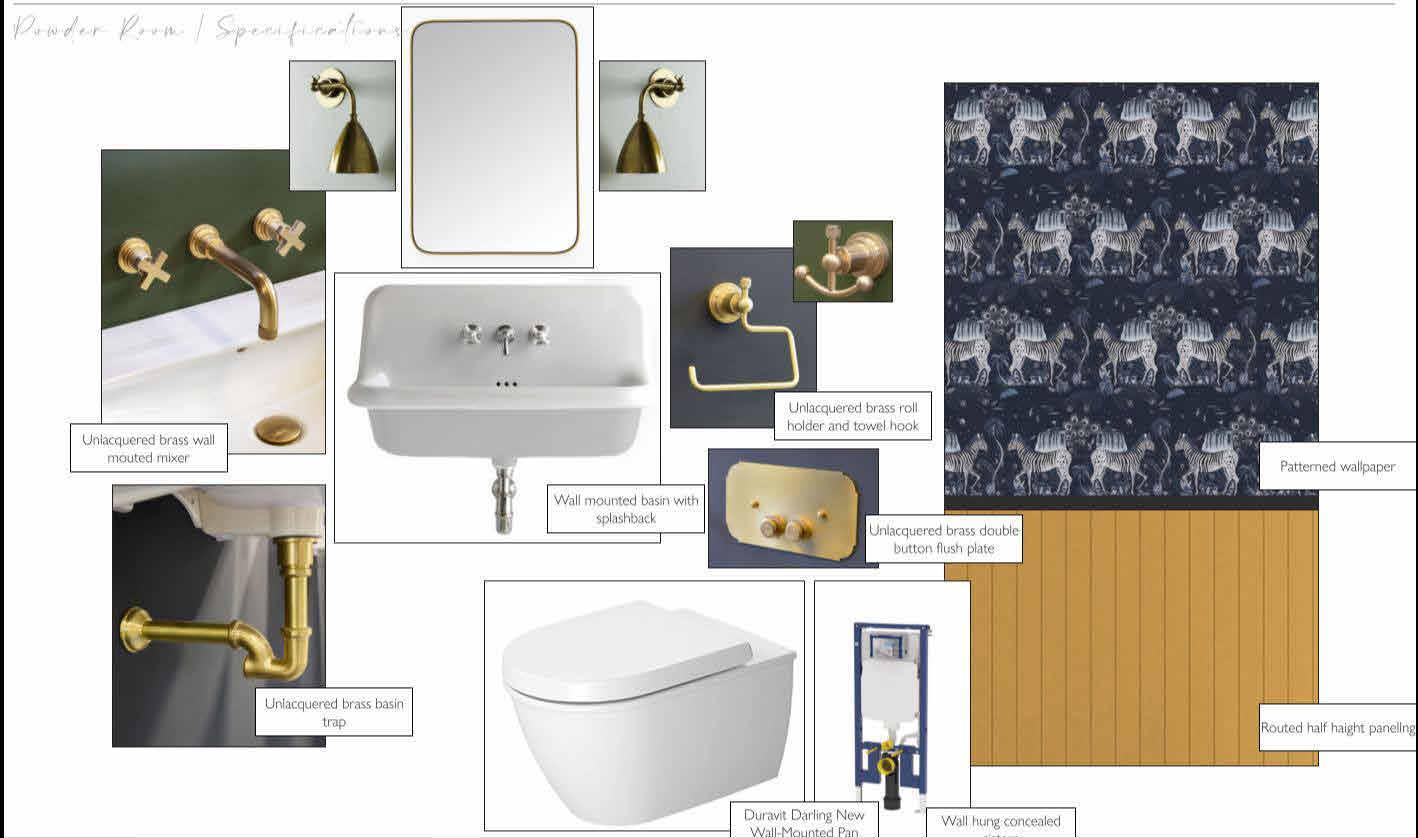
© THIS DRAWING IS THE COPYRIGHT OF DESIGNLABS LONDON LTD (DLL). It shall not be in any way used or reproduced or construct without their prior written consent. Al dimensions are to be checked on site by client or contractor prior to commencing any work. Work only to figured dimensions. Any discrepancies are to be reported to the DLL in writing and DLL shall not take responsiblity for site failing to inform discrepancies. Project : Drawing Scale Date : Rev Dwg No Status : ARCHITECTURE / INTERIOR / MANAGEMENT / PLANNING T: 07870661614 / 07888831314 E: info@designlabslondon.com W: www.designlabslondon.com DESIGNLABS LONDON Bathroom Concept 16 Priory Road, Richmond TW9 3DF NC-GR12-DR-XX-12814/10/2022 Const
Drawings Set
© THIS DRAWING IS THE COPYRIGHT OF DESIGNLABS LONDON LTD (DLL). It shall not be in any way used or reproduced or construct without their prior written consent. Al dimensions are to be checked on site by client or contractor prior to commencing any work. Work only to figured dimensions. Any discrepancies are to be reported to the DLL in writing and DLL shall not take responsiblity for site failing to inform discrepancies. Project : Drawing Scale Date : Rev Dwg No Status : ARCHITECTURE / INTERIOR / MANAGEMENT / PLANNING T: 07870661614 / 07888831314 E: info@designlabslondon.com W: www.designlabslondon.com DESIGNLABS LONDON Title Sheet- Lighting RCPs 16 Priory Road, Richmond TW9 3DF NC-GR1311/10/2022 Const Lighting RCPs (With Structures)
HD SD EQ 1275615931934 1158 1160 1181 EQ EQEQEQ 2090 19842605 1986 1363 550 950 543 EQEQ EQ EQ 1360 1110 980 980 981 980 979 7301465146514651465632 136512501421 1630 Ceiling lvl + 3100 Ceiling lvl + 3100 Ceiling lvl + 3100 Ceiling lvl + 2570 Ceiling lvl + 2560 LED Strip Lights 3 Gang Dimmer Switch: 3 no. Switches 1-way 3 Gang Dimmer switch: 2 no. Switches 2-way, 1 no. Switch 1-way. 1360 630 1375 allow for conice while setting out ceiling lights Exaust fan on light switchLED Strip Lights LED Strip Lights LED Strip Lights In internal Skylight void LED Strip Lights FAN IP IP IP IP 3 Gang Dimmer switch: 3 no. Switches 1-way 2 Gang Dimmer switch: 1 no.Switch 2-way & 1 no. Switch 1way. Wall Lights installed at 2200-2300mm ht to avoid door swing WALL MOUNTED LIGHT HEAT DETECTORHD LED STRIP LIGHT ADJUSTABLE SPOTLIGHT IP67 ADJUSTABLE SPOTLIGHT LIGHTING LEGEND SMOKE DETECTORSD PENDANT/CHANDELIER LIGHT FLOOR/TABLE LAMP IP IP67 RATED WALL MOUNTED LIGHTS @1700MM EXHAUST FANFAN LED STRIP LIGHT (IP RATE IN BATHROOMS) IP 1x DIMMER SWITCH ON PLATE 2x DIMMER SWITCH ON PLATE SWITCH LEGEND 3x RETRACTIVE TOGGLE SWITCH ON PLATE 4x DIMMER SWITCH ON PLATE 6x RETRACTIVE TOGGLE SWITCH ON PLATE 1 WAY 2 WAY WIRING LEGEND 4 WAY 3 WAY © THIS DRAWING IS THE COPYRIGHT OF DESIGNLABS LONDON LTD (DLL). It shall not be in any way used or reproduced or construct without their prior written consent. Al dimensions are to be checked on site by client or contractor prior to commencing any work. Work only to figured dimensions. Any discrepancies are to be reported to the DLL in writing and DLL shall not take responsiblity for site failing to inform discrepancies. Project : Drawing Scale Date : Rev Dwg No Status : ARCHITECTURE / INTERIOR / MANAGEMENT / PLANNING T: 07870661614 / 07888831314 E: info@designlabslondon.com W: www.designlabslondon.com DESIGNLABS LONDON As indicated Lighting RCPs PlansProposed Ground Floor RCP 16 Priory Road, Richmond TW9 3DF NC-GR13-DR-00-13011/10/2022 Const
ALL EMERGENCY LIGHTING TO BE DESIGNED & INSTALLED IN ACCORDANCE WITH BSEN1838 & BS5266(1999)
ALL SOCKET OUTLETS TO BE RCD PROTECTED (EXCLUDING TILL EQUIPMENT POWER SOCKETS) AT THE DISTRIBUTION BOARD.
FIRE ALARM SYSTEM TO BE DESIGNED IN ACCORDANCE WITH BRITISH STANDARD 5839 PART 1 & INSTALLED BY APPROVED CONTRACTOR.
ALL WORKS TO CONFORM TO CURRENT LANDLORDS FIT-OUT REQUIREMENTS.
FIRE EXIT SIGNAGE DESIGN & INSTALLATION MUST CONFORM TO BRITISH STANDARD 5499 PART 4-2000.
CEILING TO BE INSTALLED ON SOLID SUPPORTS (NOT WIRE) TO COMPLY WITH BRITISH STANDARD 8290 PART 1.
ANY ALTERATIONS TO THE FIRE ALARM SYSTEM WILL BE IN ACCORDANCE WITH BS5839 PART 1.
ANY ALTERATIONS TO THE EMERGENCY LIGHTING SYSTEM WILL BE IN ACCORDANCE WITH BS5266 PART1.
ALL DOORS/COUNTER FLAPS ON ESCAPE ROUTES WILL BE READILY OPENABLE WITHOUT THE USE OF A KEY.
NEW CEILINGS AND WALL FINISHES WILL BE SURFACE SPREAD OF FLAME RATING OF CLASS O TO CIRCULATION ROUTES, CLASS 1 ELSEWHERE, AND CLASS 3 TO SMALL ROOMS.
ALL LED STRIP LIGHTS TO HAVE CORRECT DRIVER (24V OR 12V)
1.
& LIFE SAFETY NOTES
MAIN CONTRACTOR TO COORDINATE INSTALLATIONS BY SUPPLIERS BELOW.
MUSIC SYSTEM: CLIENT ORDER DIRECT SUPPLIER THE BASE CONTROL UNIT FOR THIS SYSTEM WILL BE INSTALLED IN THE BOH AND WILL REQUIRE POWER. THIS SYSTEM MUST ALSO BE LINKED TO FIRE ALARM SYSTEM - TO CUTOUT UPON ACTIVATION OF ALARM.
2. FOOTFALL COUNTER: CHECK WITH CLIENT. CABLE CONDUIT BY MAIN CONTRACTOR TO SERVICE DESK, M&E CONTRACTOR TO FIT ELECTRIC SPUR ABOVE DOOR. ALL FOOTFALL KIT TO BE CONCEALED, OR BOH.
3. CCTV: BY CLIENT CABLING AND DATA BY MAIN CONTRACTOR POSITIONS TBC
4. INTRUDER ALARM: CLIENT NOMINATED SUPPLIER M&E CONTRACTOR TO PROVIDE POWER AND SPURS AS REQUIRED IN BOTH FRONT AND BACK OF HOUSE. EQUIPMENT LOCATIONS TO BE AGREED. MAIN CONTRACTOR AND FIRE DETECTION CONTRACTOR TO LIASE WITH NOMINATED SUPPLIER WITH REFERENCE TO INSTALLATIONS AND SENSITIVITY OF SYSTEMS RELATIVE TO OTHER FITTINGS.
5. IT EQUIPMENT: DIRECT ORDER
6. BT INSTALLATION: DIRECT ORDER SUPPLIER
7. HEARING LOOP INSTALLATION: NOT APPLICABLE.
8. CONTRACTOR TO CHECK DIMMING/NON-DIMMING FUNCTION WITH CLIENT.
RCP & LIFE SAFETY NOTES
ALL NEW INTERNAL CORRIDOR AND ROOM DOOR SETS ARE TO BE MINIMUM OF 950MM WIDE DESIGNED TO GIVE A CLEAR DIMENSION FROM FACE OF OPEN DOOR LEAF TO OPPOSITE DOOR JAM OF 800MM - BUILDING REGULATIONS PART M COMPLIANCE.
NEW ACCESSABLE TOILET DOOR MUST BE 1000MM OVERALL SET OTHER CUSTOMER/STAFF TOILETS ENTRANCE DOOR SETS TO BE A MINIMUM OF 950MM WIDE OVERALL.
FD30 S VP SC -30MIN FIRE DOOR CONSTRUCTION (FD30) WITH INTUMESCENT SEALS INCLUDING SMOKE STOPS (S) WITH VISION PANELS (VP AND DOOR CLOSURE (SC). FD60 DOORS TO BE USED WHERE STATED.
VISION PANELS IN FIRE DOORS TO BE CONSTRUCTED IN PYROBEL 12 OR SWISS FLAM CLEAR GLAZING TO GIVE 30MIN PROTECTION. VISION PANELS TO BE APPROX 1450MM X 150MM WIDE EXTENDING TO WITHIN 300MM OF DOOR TOP AND 300MM OF DOOR BOTTOM AND INSET BY 225MM FROM OPEN SIDE.
DOORS TO KITCHEN TO HAVE HIGH LEVEL VISION PANELS WITH 500MM STAINLESS STEEL KICKPLATES TO BASE AND DOUBLE SING HINGE. DOOR LEADING FROM PUBLIC SPACES TO BACK OF HOUSE TO BE FITTED WITH ELECTRONIC ACCESS KEPYPAD.
ALL FIRE DOORS TO HAVE SELF CLOSURE DEVICES WITH 'FIRE DOOR KEPT SHUT' SIGNS FITTED TO BOTH SIDES.
ALL FIRE DOORS NOT FITTED WITH SELF CLOSURE DEVICES TO BE FITTED WITH 'FIRE DOOR KEEP SHUT' SIGNAGE. SELF CLOSURES MUST BE DESIGNED TO SUIT DOOR WEIGHT AND SIZE, BUT SET TO AN OPENING STRENGTH NO GREATER THAN 20N.
IRONMONGERY: DOOR FURNITURE, HANDLES, KICK PLATES/PUSH PLATES ALL TO BE STAINLESS STEEL SATIN FINISH. SEE FINISHES FOR DETAILS. DOOR FINISHES: ALL DOORS TO BE DECORATED ON SITE WITH 1 COAT PRIMER AND 2 COATS EGSHELL PAINT PT03. ARCHITRAVE PT03 FINAL FIRE EXIT DOORS TO BE FITTED WITH EMERGENCY RELEASE ESCAPE IRONMONGERY TO PART B BUILDING REGULATIONS AND BS 9999. ADDITIONAL LAST MAN OUT EASY RELEASE SECURING DEVICE MAY BE FITTED IN COMPLIANCE WUTH BS 9999, PROVIDING THAT THE USE IS FACTORED INTO CLIENTS RISK ASSESMENT.
LIGHTING LEGEND
ADJUSTABLE SPOTLIGHT
IP67 ADJUSTABLE SPOTLIGHT
PENDANT/CHANDELIER LIGHT
FLOOR/TABLE LAMP
WALL MOUNTED LIGHT
IP
LED STRIP LIGHT
SMOKE DETECTORSD
HEAT DETECTORHD
IP IP67 RATED WALL MOUNTED LIGHTS @1700MM EXHAUST FANFAN
LED STRIP LIGHT (IP RATE IN BATHROOMS)
• • • • • • • • • • •
RCP
• • • • • • • • • • • •
RCP & LIFE SAFETY NOTES © THIS DRAWING IS THE COPYRIGHT OF DESIGNLABS LONDON LTD (DLL). It shall not be in any way used or reproduced or construct without their prior written consent. Al dimensions are to be checked on site by client or contractor prior to commencing any work. Work only to figured dimensions. Any discrepancies are to be reported to the DLL in writing and DLL shall not take responsiblity for site failing to inform discrepancies. Project : Drawing Scale Date : Rev Dwg No Status : ARCHITECTURE / INTERIOR / MANAGEMENT / PLANNING T: 07870661614 / 07888831314 E: info@designlabslondon.com W: www.designlabslondon.com DESIGNLABS LONDON As indicated Lighting Notes 16 Priory Road, Richmond TW9 3DF NC-GR13-DR-02-13311/10/2022 Const
Layouts
© THIS DRAWING IS THE COPYRIGHT OF DESIGNLABS LONDON LTD (DLL). It shall not be in any way used or reproduced or construct without their prior written consent. Al dimensions are to be checked on site by client or contractor prior to commencing any work. Work only to figured dimensions. Any discrepancies are to be reported to the DLL in writing and DLL shall not take responsiblity for site failing to inform discrepancies. Project : Drawing Scale Date : Rev Dwg No Status : ARCHITECTURE / INTERIOR / MANAGEMENT / PLANNING T: 07870661614 / 07888831314 E: info@designlabslondon.com W: www.designlabslondon.com DESIGNLABS LONDON Title Sheet - Electrical & Small Power Layouts (With Furniture) 16 Priory Road, Richmond TW9 3DF NC-GR1411/10/2022 Const Electrical & Small Power
(With Furniture)
DN TV TV LL USB USBUSB USBUSB LL LL LL LL LL LL LL LL LL LL LL LL LL LL HL HL LL LL ELECTRICAL LEGEND SWITCHED DOUBLE SOCKET OUTLET- BRONZE FINISH IN VISIBLE AREAS ONLY; STANDARD WHITE FINISH TO SOCKET IN JOINERY SWITCHED SINGLE SOCKET OUTLET- BRONZE FINISH S SHAVER POINT- BRONZE FINISH TV/SKY/VIRGIN CABLE POINT- BRONZE FINISHTV TELEPHONE SOCKET- BRONZE FINISH UNSWITCHED SINGLE SOCKET OUTLET- BRONZE FINISH IN VISIBLE AREAS ONLY; STANDARD WHITE FINISH TO SOCKET IN JOINERY SPUR/ISOLATOR 1 GANG DIMMER SWITCH ON PLATE - BRONZE FINISH REFER TO PLAN FOR SWITCH TYPE 2 GANG DIMMER SWITCH ON PLATE - BRONZE FINISH REFER TO PLAN FOR SWITCH TYPE 3 GANG DIMMER SWITCH ON PLATE - BRONZE FINISH REFER TO PLAN FOR SWITCH TYPE PULL CORD SWITCH © THIS DRAWING IS THE COPYRIGHT OF DESIGNLABS LONDON LTD (DLL). It shall not be in any way used or reproduced or construct without their prior written consent. Al dimensions are to be checked on site by client or contractor prior to commencing any work. Work only to figured dimensions. Any discrepancies are to be reported to the DLL in writing and DLL shall not take responsiblity for site failing to inform discrepancies. Project : Drawing Scale Date : Rev Dwg No Status : ARCHITECTURE / INTERIOR / MANAGEMENT / PLANNING T: 07870661614 / 07888831314 E: info@designlabslondon.com W: www.designlabslondon.com DESIGNLABS LONDON 1 25 Ground Floor - Small Power layout 16 Priory Road, Richmond TW9 3DF NC-GR14-DR-00-14111/10/2022 Const
