Sheet Schedule

© THIS DRAWING IS THE COPYRIGHT OF DESIGNLABS LONDON LTD (DLL). It shall not be in any way used or reproduced or construct without their prior written consent. Al dimensions are to be checked on site by client or contractor prior to commencing any work. Work only to figured dimensions. Any discrepancies are to be reported to the DLL in writing and DLL shall not take responsiblity for site failing to inform discrepancies. Project Drawing : Scale Date Rev Dwg No Status ARCHITECTURE / INTERIOR / MANAGEMENT / PLANNING T: 07870661614 / 07888831314 E: info@designlabslondon.com W: www.designlabslondon.com DESIGNLABS LONDON Title Sheet - Sheet Schedule 11 Ennerdale Road. Richmond. TW9 3PG NC-GR015/07/2022 Construction
NC-GR0
NC-GR0-SC-001
NC-GR0-SP-100
15/07/2022 Construction Site Issue
NC-GR0-SP-101 Specification 15/07/2022 Construction Site Issue
NC-GR0-SP-102. Specification 15/07/2022 Construction Site Issue
NC-GR1 Title Sheet- New Wall & Demolition Plan 15/07/2022 Construction Site Issue
NC-GR1-DR-00-09 Basement New Wall And Demolition Plan 15/07/2022 Construction Draft
NC-GR1-DR-00-010 Ground Floor New Wall and Demolition Plan 2 15/07/2022 Construction Site Issue
NC-GR1-DR-01-011 First Floor New Wall and Demolition Plan 15/07/2022 Construction Site Issue
NC-GR1-DR-02-012 Second Floor New Wall and Demolition Plan 1 15/07/2022 Construction Site Issue
NC-GR2 Title Sheet- Setting-Out Sheets 15/07/2022 Construction Site Issue
NC-GR2-DR-00-019 Setting-Out Plans'- Proposed Basement Floor Plan 15/07/2022 Construction Draft
NC-GR2-DR-00-020 Setting-Out Plans'- Proposed Ground Floor Plan 5 15/07/2022 Construction Site Issue
NC-GR2-DR-01-021 Setting-Out Plans'- Proposed First Floor Plan 2 15/07/2022 Construction Site Issue
NC-GR2-DR-02-022 Setting-Out Plans'- Proposed Second Floor Plan 2 15/07/2022 Construction Site Issue
NC-GR2-DR-02-022. 1 Roof Trimmer Setting Out Plan and 3D 1 15/07/2022 Construction Site Issue
NC-GR2-DR-03-023 Setting-Out Plans'- Proposed Roof Floor Plan 3 15/07/2022 Construction Site Issue
NC-GR2-DR-XX-030 Setting-Out Sections'- Proposed Sections 3 15/07/2022 Construction Site Issue
NC-GR2-DR-XX-031 Setting-Out Sections'- Proposed Sections 3 15/07/2022 Construction Site Issue
NC-GR2-DR-XX-032 Setting-Out Sections'- Proposed Sections 2 15/07/2022 Construction Site Issue
NC-GR2-DR-XX-033 Setting-Out Sections'- Proposed Sections 2 15/07/2022 Construction Site Issue
NC-GR2-DR-YY-034 Setting-Out Sections'- Proposed Sections 1 15/07/2022 Construction Site Issue
NC-GR2-DR-YY-035 Setting-Out Elevations'- Proposed Elevations 2 15/07/2022 Construction Site Issue
NC-GR2-DR-YY-036 Setting-Out Elevations'- Proposed Elevations 1 15/07/2022 Construction Site Issue
NC-GR2-DR-YY-037 Setting-Out Elevations'- Proposed Elevations 1 15/07/2022 Construction Draft
NC-GR2-DR-YY-038 Setting-Out Sections'- Proposed Detail Callout 1 15/07/2022 Construction Site Issue
NC-GR2-DR-YY-039 Setting-Out Sections'- Proposed Detail Callout 15/07/2022 Construction Site Issue
NC-GR2-DR-YY-040 Setting-Out Sections'- Proposed Basement Details 15/07/2022 Construction Draft
NC-GR5-SC-00-052 Window Schedule 15/07/2022 Construction Site Issue NC-GR5-SC-00-053 Door Schedule 1 15/07/2022 Construction Draft
© THIS DRAWING IS THE COPYRIGHT OF DESIGNLABS LONDON LTD (DLL). It shall not be in any way used or reproduced or construct without their prior written consent. Al dimensions are to be checked on site by client or contractor prior to commencing any work. Work only to figured dimensions. Any discrepancies are to be reported to the DLL in writing and DLL shall not take responsiblity for site failing to inform discrepancies. Project Drawing : Scale Date Rev Dwg No Status ARCHITECTURE / INTERIOR / MANAGEMENT / PLANNING T: 07870661614 / 07888831314 E: info@designlabslondon.com W: www.designlabslondon.com DESIGNLABS LONDON Sheet Schedule 11 Ennerdale Road. Richmond. TW9 3PG NC-GR0-SC-00115/07/2022 Construction Project No: Project: 11 Ennerdale Road, Richmond. Drawings Issue Sheet Sheet Number Sheet Name Current Revision Sheet Issue Date Project Status Sheet Status
Title Sheet Sheet Schedule 15/07/2022 Construction Site Issue
Sheet Schedule 15/07/2022 Construction Site Issue
Specification Sheets Title
Specification
© THIS DRAWING IS THE COPYRIGHT OF DESIGNLABS LONDON LTD (DLL). It shall not be in any way used or reproduced or construct without their prior written consent. Al dimensions are to be checked on site by client or contractor prior to commencing any work. Work only to figured dimensions. Any discrepancies are to be reported to the DLL in writing and DLL shall not take responsiblity for site failing to inform discrepancies. Project Drawing : Scale Date Rev Dwg No Status ARCHITECTURE / INTERIOR / MANAGEMENT / PLANNING T: 07870661614 / 07888831314 E: info@designlabslondon.com W: www.designlabslondon.com DESIGNLABS LONDON Specification Sheets Title 11 Ennerdale Road. Richmond. TW9 3PG NC-GR0-SP-10015/07/2022 Construction
GENERAL CONSTRUCTION NOTE TO COMPLY THE CONSTRUCTION WITH BUILDING REGULATION
GENERAL
THE FOLLOWING SPECIFICATION MUST BE READ IN CONJUNCTION WITH ALL ARCHITECTURAL GENERAL ARRANGEMENT DRAWINGS, SCHEDULES ETC. AND IS APPLICABLE WHETHER SPECIFICALLY REFERRED TO OR NOT. IT IS THE RESPONSIBILITY OF THE CONTRACTOR/SUB-CONTRACTOR TO ENSURE THAT
THEIR WORK IS IN COMPLIANCE WITH THE APPROPRIATE REQUIREMENTS OF THE RELEVANT BUILDING REGULATIONS, NHBC STANDARDS AND OTHER ALLIED LEGISLATION.
ALL MATERIALS ARE TO BE USED AND INSTALLED IN ACCORDANCE WITH THE RELEVANT MANUFACTURER'S INSTRUCTIONS AND RECOMMENDATIONS. ALL NEW SERVICES ARE TO BE PROVIDED IN ACCORDANCE WITH THE STATUTORY UNDERTAKER'S REQUIREMENTS. THE QUALITY OF ANY MATERIAL SHALL NOT BE LOWER THAN THAT DEFINED IN THE RELEVANT BRITISH STANDARD, OR THAT THE MATERIAL HAS BEEN SATISFACTORILY ASSESSED BY AN APPROPRIATE INDEPENDENT AUTHORITY I.E. BBA, BRE.
THE CONTRACTOR/SUB-CONTRACTOR MUST ENSURE THAT MATERIALS ARE 'FULLY SUITABLE' FOR THEIR LOCATION AND THAT ALLIED MATERIALS/BACKGROUNDS ARE APPROPRIATE. WHERE THERE IS NO LEGISLATED STANDARD, THE QUALITY AND USE OF THE PRODUCT SHALL BE IN ACCORDANCE WITH ESTABLISHED SATISFACTORY CUSTOMS AND PRACTICES. ALL WORK SHALL BE CARRIED OUT IN A SOUND, NEAT, DURABLE AND WORKMANLIKE MANNER. REASONABLE PRECAUTIONS SHALL BE TAKEN TO PROTECT FIXED AND UNFIXED MATERIALS AGAINST ANY DAMAGE LIKELY TO AFFECT THE FINISHED QUALITY OF THE BUILDING.
ALL CONTRACTORS/SUB-CONTRACTORS MUST ENSURE TO THEIR OWN SATISFACTION THAT THEY ARE IN POSSESSION OF THE CURRENTLY ISSUED DRAWINGS AND DETAILS, BEFORE COMMENCING THE RELEVANT 'WORK-STAGE' ON SITE.
NOTE: UNLESS STATED ALL CONSTRUCTION DETAILS ARE TO BE IN ACCORDANCE WITH THE ROBUST DETAILS DOCUMENT - LIMITING THERMAL BRIDGING AND AIR LEAKAGE PUBLISHED BY DTLR.
THE PRINCIPLE CONTRACTOR IS TO ENSURE THAT THE PROVISIONS OF THE CONSTRUCTION DESIGN MANAGEMENT (CDM) REGULATIONS ARE CARRIED OUT FULLY, INCLUDING ALL NOTIFICATIONS OF WORK REQUIRED UNDER LEGISLATION, PRIOR TO START OF WORKS.
FOUNDATIONS
THE EXISTING GROUND WITHIN THE EXTENT OF THE PROPOSED BUILDING CONSTRUCTION SITE SHALL BE CLEARED OF ALL TURF AND VEGETABLE MATTER PRIOR TO ANY FURTHER EXCAVATION BEING MADE. METHOD OF DISPOSAL OF ANY CONTAMINATED SOIL TO BE AGREED WITH THE LOCAL ENVIRONMENTAL OFFICER. FOUNDATION TRENCHES SHALL BE CLEAN AND TRUE AND CHECKED FOR SOFT AREAS, WATER ETC. AND LEFT WITH COMPACTED BOTTOMS.
FOUNDATIONS SHALL BE LOCATED CENTRALLY UNDER EXTERNAL AND LOAD BEARING INTERNAL WALLS UNLESS IS IT INDICATED IN ARCHITECTURAL DRAWINGS. ALL FOUNDATIONS SHALL BE DESIGNED WITH DUE REGARD TO SUBSOIL CONDITIONS, WATER TABLE, PRESENCE OF SULPHATES AND PREVIOUS GROUND USES ETC. DEPTH OF THE FOUNDATIONS TO SUIT SOIL CONDITIONS, ORIGINAL AND PROPOSED GROUND LEVELS, DRAINAGE TRENCHES AND PROXIMITY OF TREES/HEDGES, ALL TO THE SATISFACTION OF THE RELEVANT BUILDING CONTROL AUTHORITY/NHBC INSPECTOR. READY MIXED CONCRETE WILL ONLY BE ACCEPTABLE FROM SUPPLIERS USING A FULL QUALITY CONTROL SYSTEM.
ENTIRE FOUNDATION DESIGN TO BE IN-ACCORDANCE WITH STRUCTURAL ENGINEERS DESIGN DRAWINGS AND CALCULATIONS.
CONTRACTOR / SUB-CONTRACTOR TO MAKE SURE THERE IS NO ENCROACHMENTS ON SITE.
BELOW GROUND DRAINAGE
ALL DRAINAGE WORKS SHALL BE IN FULL ACCORDANCE WITH APPROVED DOCUMENT H OF THE BUILDING REGULATIONS, BS 8301 AND TO THE COMPLETE SATISFACTION OF THE RELEVANT BUILDING CONTROL BODY.
WHERE DRAINS PASS THROUGH EXTERNAL WALLS THEY ARE TO BE PROTECTED WITH A PRE-STRESSED CONCRETE LINTEL OVER (AS DESIGNED BY ENGINEER) WITH MIN. 150MM END BEARINGS, WITH 150MM CLEARANCE ALL ROUND PIPE AND THE OPENING IS TO BE MASKED WITH RIGID SHEET MATERIAL TO PREVENT THE INGRESS OF VERMIN OR FILL.
IF APPLICABLE, REFER TO DRAINAGE ENGINEER'S DETAILED DRAWINGS FOR DRAINAGE LAYOUT AND SPECIFICATION DETAILS.
GROUND FLOOR CONSTRUCTION
GROUND FLOOR CONSTRUCTION AS INDICATED IN ARCHITECTURAL GENERAL ARRANGEMENT DRAWINGS AND TO BE CONFIRMED BY ENGINEER.
GROUND BEARING FLOOR 75MM REINFORCED SAND/CEMENT SCREED (UNDER FLOOR HEATING TO SPECIALIST'S DESIGN - TO BE CONFIRMED BY THE END USE) ON 1200G POLYTHENE PROTECTION LAYER ON 100MM GA4000 CELOTEX INSULATION (FF4000 FOR UNDER FLOOR HEATING) OR SIMILAR APPROVED ON 1200G DPM ON 150MM CONCRETE GROUND BEARING FLOOR SLAB WITH A393 MESH REINFORCEMENT WITH MIN. 50MM COVER, (ENGINEER TO CONFIRM), ON BRICK BALLAST/CRUSHED STONE BASE ON WELL COMPACTED SOIL 25MM CELOTEX INSULATION STRIP TO BE PROVIDED TO ALL PERIMETER WALLS. CONSTRUCTION TO ACHIEVE U-VALUE OF 0.16
PLEASE NOTE FOR EXTENSIONS ANY EXISTING FLOOR VENTS TO BE CONNECTED WITH 4" PIPE AND VENTED TO EXTERNAL LEAF.
MOVEMENT JOINTS
REFER TO FLOOR PLANS AND STRUCTURAL ENGINEERS DETAILS FOR RECOMMENDED LOCATION OF MOVEMENT JOINTS TO OUTER LEAF BRICKWORK/BLOCKWORK, GENERALLY TO BE PROVIDED AT NOT GREATER THAN 6 METRE CENTRES FOR BLOCKWORK AND 12-15 METRE CENTRES FOR BRICKWORK. MOVEMENT JOINTS TO BE 10MM MINIMUM WIDE, LOCATED BEHIND RAIN WATER DOWN PIPES WHERE POSSIBLE AND FORMED WITH PROPRIETARY POLYURETHANE SEALING STRIP, WITH FLAT TIES BETWEEN PANELS AT 450MM VERTICAL CENTRES WITH ONE END DE-BONDED WITH POLY-SULPHIDE SEALANT TO EXTERNAL FACE OF BRICKWORK - COLOUR TO MATCH. NOTE PROVIDE CAVITY WALL TIES WITHIN 150MM HORIZONTALLY, AT 225MM MAXIMUM VERTICAL CENTRES, EITHER SIDE OF MOVEMENT JOINTS.
EXTERNAL CAVITY WALL
CAVITY WALLS TO COMPLY WITH BS 5628.
300MM EXTERNAL WALL CONSTRUCTION ABOVE DPC COMPRISING 100MM AIRCRETE BLOCKWORK (TC 0.11) INNER SKIN, STRENGTH TO BE 7.3 N/MM.SQ, 12.5MM PLASTERBOARD ON DABS, STRICTLY IN ACCORDANCE WITH THE MANUFACTURER'S RECOMMENDATIONS. ALL WALLS ARE TO RECEIVE A PLASTER SKIM FINISH READY TO RECEIVE DECORATION.
CAVITY TO BE FULLY FILLED WITH 97MM KNAUF SUPAFIL 37 (TC 0.037) OR SIMILAR APPROVED IN ACCORDANCE WITH MANUFACTURERS DETAILS. OUTER LEAF GENERALLY TO BE 102.5MM (FL DURABILITY) FACING BRICKWORK TO LOCAL AUTHORITY APPROVAL. TOTAL EXTERNAL CAVITY WALL TO ACHIEVE MINIMUM 'U' VALUE 0.26 W PER M2K.
LOWER CAVITY IS TO BE FILLED WITH A LEAN MIX CONCRETE UP TO A LEVEL OF 225MM MINIMUM BELOW DPC & IS TO BE LAID WITH SULPHATE RESISTANT MORTAR. PROVIDE PERPEND WEEPHOLES EVERY FOURTH VERTICAL JOINT IN THE OUTER LEAF AT THE BASE OF THE CAVITY AT 150MM BELOW D.P.C.
PROVIDE PROPRIETARY INSULATED CAVITY CLOSERS AT ALL WINDOW/DOOR OPENINGS AND CLOSE CAVITY AT TOP WITH INSULATED LINTEL.
CONSTRUCTION
ROOF DESIGNER/STRUCTURAL ENGINEER TO BE RESPONSIBLE FOR THE DESIGN OF THE WHOLE FOR THE ROOF INCLUDING ALL NECESSARY WIND BRACING ETC IN ACCORDANCE WITH BS5268: PART 3. ROOF TIMBERS DESIGNED AROUND A 200MM DEEP RAFTER.
ROOFING TILES AS SPECIFIED IN ARCHITECTURAL DRAWINGS (TO BS 5534 PT.1
AMENDED 1981) LAID WITH PITCH AND LAP IN ACCORDANCE WITH MANUFACTURER'S INSTRUCTIONS ON 50X38MM SW BATTENS (SIZE TO BE N ACCORDANCE WITH BS 5534) ON 'TYVEK SUPRO' OR SIMILAR APPROVED VAPOUR PERMEABLE BREATHER MEMBRANE. MEMBRANE DRESSED INTO GUTTERS ON 'TYVEK' EAVES CARRIER. ON SW PRE FABRICATED TRUSSED RAFTERS AND BRACINGS TO BS 5268 PART 3 1985, AT MAX 600 CTS. 30X5G.S RESTRAINT STRAPS AT VERGE AND CEILING LEVEL. PROVIDE AND BED ON 1:1:6
MORTAR 100X50MM SW TREATED WALL PLATE WITH RESTRAINT STRAPS TO WALL PLATE AT MAX 2 M CTS. TO BS 5628 PART 1. ALL EXTERNAL TIMBERS TO BE PRESERVATIVE TREATED.
SLOPING CEILING - MINIMUM 150MM DEEP LOOSE RAFTERS TRUSS RAFTERS AT 400C/C TO ROOF MANUFACTURER'S OR ENGINEER'S DESIGN AND DETAILS. AT SLOPING SCEILING, BREATHABLE ROOFING MEMBRANE WITH 100MM CELOTEX GA4000 OR SIMILAR APPROVED INSULATION BETWEEN RAFTERS WITH MIN 50MM VOID OVER INSULATION AND CELOTEX GD5025 (25+9.5) OR EQUIVALENT UNDER RAFTERS WITH VAPOUR CHECK LAYER, ROOF
CONSTRUCTION TO ACHIEVE MIN. U-VALUE OF 0.18
FLAT ROOF LOFT VOID - ROOF INSULATION TO FLAT CEILING AREAS TO BE 350MM GLASS FIBRE INSULATION QUILT LAID IN 3 LAYERS. 100MM LAID BETWEEN TRUSSED RAFTERS/CEILING JOISTS AND 2 LAYERS 125MM CROSS LAID AT RIGHT ANGLES OVER.
THE FIRST LAYER IS TO EXTEND THROUGH EAVES TO BUTT AGAINST THE CAVITY CLOSER AT THE TOP OF THE EXTERNAL WALL.
FLAT ROOF AT RAFTER LEVEL (WARM FLAT ROOF) FIBER GLASS WATER PROOFING LAYER OR SIMILAR APPROVED TO MANUFACTURER'S INSTRUCTIONS AND DETAILS. ON 18MM OSB 3 BOARD, ON 120MM CELOTEX RIGID INSULATION OR SIMILAR APPROVED WITH VAPOUR CONTROL LAYER ON BOTH SIDES, ON 12MM OSB2 BOARD, ON SW FURRINGS TO GIVE MINIMUM 1:60 FALL, ON 150/200MM JOISTS (TBC BY ENGINEER), 15MM CEILING BOARD WITH VAPOUR CONTROL LAYER, CONSTRUCTION TO ACHIEVE U-VALUE OF 0.18
DAMP PROOF COURSE
HORIZONTAL DAMP PROOF COURSE TO BE MINIMUM 150MM ABOVE ADJACENT GROUND LEVEL. A SECONDARY DPC WILL BE PROVIDED 150MM ABOVE FLOOR LEVEL FOR MINIMUM DISTANCE OF 1.5M FROM ALL EXTERNAL DOORS WITH A LEVEL THRESHOLD. DPC/ CAVITY TRAY TO BE MARLEY AQUAGARD OR SIMILAR APPROVED AND IS TO BE INSTALLED STRICTLY IN ACCORDANCE WITH THE MANUFACTURERS INSTRUCTIONS AND RECOMMENDATIONS.
IF THE EXTERNAL GROUND LEVEL IS EQUAL OR ABOVE THE INTERNAL FINISH FLOOR LEVEL, THEN DOUBLE DPC TO BE PROVIDED, ONE AT FINISHED FLOOR LEVEL AND THE SECONDARY 150MM ABOVE EXTERNAL GROUND LEVEL. BOTH HORIZONTAL DPC'S TO BE CONNECTED WITH AND VERTICAL LAYER OF DPC ALL IN ACCORDANCE WITH ARCHITECTURAL DESIGN AND DETAILS.
CAVITY CLOSURE TO ALL WINDOWS AND DOORS TO REPLACE ALL VERTICAL DPC'S AND IN ORDER TO AVOID COLD BRIDGING.
THE HORIZONTAL DAMP PROOF COURSE SHALL CONSIST OF A LAYER OF 2000 GAUGE POLYTHENE DAMP COURSE TO BS 743/6515 ADEQUATELY LAPPED AT CORNERS AND JOINTS AND LAID ON A MORTAR BED.
WHERE EXTERNAL WALL CAVITY IS BRIDGED I.E. AIR BRICK/VENTILATOR OPENINGS AND METER CUPBOARD ETC. PROVIDE POLYTHENE CAVITY TRAYS COMPLETE WITH STOP ENDS OVER IN THE EXTERNAL WALL WITH OPEN PROPRIETARY PERPENDS. CAVITY TRAYS ARE TO PROJECT 150MM BEYOND EITHER SIDE OF LINTEL/OPENING.
AT ALL ROOF ABUTMENTS I.E PORCHES, GARDEN ROOMS ENSURE STEPPED D.P.C'S CAVITY TRAY WITH STOP ENDS ARE PROVIDED AND LINKED TO CODE 4 LEAD FLASHINGS AND SOAKERS. CODE 4 LEAD DRESSED BENEATH CAVITY TRAYS AND OVER ROOF SLOPES WITH ALTERNATE PERPENDS LEFT OPEN FOR WEEPHOLES ALL AS NECESSARY TO FORM WEATHER PROOF JUNCTION. ALL LEADWORK TO SOAKERS, FLASHINGS, VALLEYS ETC. ARE TO BE IN COMPLIANCE WITH THE RECOMMENDATIONS OF THE LATEST EDITION OF THE LEAD SHEET ASSOCIATION'S 'GUIDE TO GOOD PRACTICE'.
INTERNAL WALLS
INTERNAL PARTITIONS TO BE BRITISH GYPSUM 'GYPWALL' METAL STUD-PARTITIONING SYSTEM OR APPROVED TIMBER STUDS, TOTAL OVERALL THICKNESS 95MM. USING 70MM METAL /TIMBER STUDS AT 600MM CTRS. WITH 12.5MM BRITISH GYPSUM 'SOUNDBLOC' BOTH SIDES (MOISTURE RESISTANT TO BATHROOM & ENSUITES). PARTITION TO ACHIEVE 40DB SOUND REDUCTION.
PARTITIONS PARALLEL TO THE SPAN ARE TO BE LOCATED ON MULTIPLE JOISTS WHERE POSSIBLE AS RECOMMENDED BY ENGINEERED JOIST MANUFACTURER AND STRUCTURAL ENGINEER, OR SUPPORTED BY CLIPPED NOGGINS AS DETAILED BY MANUFACTURER..
ADDITIONAL 12.5MM STRUCTURAL PLY BOARD TO BE ADDED BETWEEN/ABOVE BATTENS TO SUPPORT THE KITCHEN/BATHROOM FITTINGS AND APPLIANCES.
FLAT ROOF (COLD ROOF) , FIBER GLASS WATER PROOFING LAYER OR SIMILAR APPROVED TO MANUFACTURER'S INSTRUCTIONS AND DETAILS. ON 18MM OSB 3 BOARD, ON SW FURRINGS TO GIVE MINIMUM 1:60 FALL, ON 150/200MM JOISTS (TBC BY ENGINEER), THE JOISTS SHOULD BE PROVIDED EITHER WITHOUT CEILING BOARD OR 10MM WIDE AIR GAP TO BE PROVIDED TO ALL SIDES FOR CROSS VENTILATION.
ALLOW FOR CUTTING THE OVERHANGING RAFTER FEET SQUARELY TO ACHIEVE PERFECT VERTICAL ALIGNMENT TO THE NEW FASCIA BOARDS, AS WELL AS A CONSTANT SOFFIT WIDTH.
TRUSSES TO BE SECURED TO WALL PLATES USING PROPRIETARY TRUSS CLIPS WITH NAILS FIXED THROUGH EACH AVAILABLE HOLE.
FORM HIPS AND RIDGE USING PROPRIETARY RIDGE AND BONNET HIP TILES, & CODE 5 LEAD ON VALLEY BOARDS IN ACCORDANCE WITH LEAD ASSOCIATION DETAILS,(ALTERNATIVELY A GRP VALLEY CAN BE USED AND INSTALLED STRICTLY IN ACCORDNACE WITH MANUFACTURES / SUPPLIERS GUJIDLINES AND RECOMMENDATIONS.
PROVIDE CAVITY TRAYS & CODE 4 STEPPED AND APRON LEAD FLASHINGS AT ABUTMENTS OF ALL ROOFS WITH WALLS, LEAD CHASED INTO WALLS AND WEDGED AT MAXIMUM 450MM CENTRES AND POINTED IN 1:3 CEMENT/ SAND MORTAR. PROVIDE SOAKERS TO HIPS, VALLEYS AND ROOF/ WALL ABUTMENTS.
UPPER FLOORS
UPPER FLOOR IN ACCORDANCE WITH SPECIALISTS'S DESIGN AND DETAILS 18-22MM THICK MOISTURE-RESISTANT FLOORING TYPE C4 CHIPBOARD TO B.S 5669, ENSURE THROUGHOUT EDGES OF BOARDS SUPPORTED ON JOISTS OR NOGGINS, WITH 10MM EXPANSION GAP AT ROOM PERIMETERS BETWEEN CHIPBOARD AND WALLS.
BOARDS TO BE SECURELY FIXED THROUGH TO 50X200MM (TBC BY ENGINEER) DEEP C24 TIMBER JOIST SYSTEM OR ATTIC TRUSSES AT CENTRES AS SPECIFIED BY SPECIALIST MANUFACTURER/ STRUCTURAL ENGINEER. THE ENTIRE FLOOR IS TO BE INSTALLED IN STRICT ACCORDANCE WITH THE MANUFACTURER'S INSTRUCTIONS - STANDARD DETAILS AND SETTING OUT
JOISTS TO BE SUPPORTED ON HANGERS AT PARTY WALL AND EXTERNAL WALL. AT PARTY WALLS THE JOISTS ARE TO BE SEALED FOR FIRE AND ACOUSTIC REQUIREMENTS IN STRICT ACCORDANCE WITH THE MANUFACTURERS INSTRUCTIONS.
UNDERSIDE OF JOISTS TO RECEIVE 12.5MM SOUNDBLOCK PLASTERBOARD CEILING, TAPED, SKIMMED AND SET FINISHED. FLOOR VOID TO HAVE 100MM THICK MINERAL FIBRE INSULATION FOR SOUND REDUCTION.
OVERALL CONSTRUCTION TO ACHIEVE MINIMUM AIRBORNE SOUND REDUCTION OF 40DB
PROVIDE CAVITY TRAYS & CODE 4 STEPPED AND APRON LEAD FLASHINGS AT ABUTMENTS OF ALL ROOFS WITH WALLS, LEAD CHASED INTO WALLS AND WEDGED AT MAXIMUM 450MM CENTRES AND POINTED IN 1:3 CEMENT/ SAND MORTAR. PROVIDE SOAKERS TO HIPS, VALLEYS AND ROOF/ WALL ABUTMENTS.
© THIS DRAWING IS THE COPYRIGHT OF DESIGNLABS LONDON LTD (DLL). It shall not be in any way used or reproduced or construct without their prior written consent. Al dimensions are to be checked on site by client or contractor prior to commencing any work. Work only to figured dimensions. Any discrepancies are to be reported to the DLL in writing and DLL shall not take responsiblity for site failing to inform discrepancies. Project Drawing : Scale Date Rev Dwg No Status ARCHITECTURE / INTERIOR / MANAGEMENT / PLANNING T: 07870661614 / 07888831314 E: info@designlabslondon.com W: www.designlabslondon.com DESIGNLABS LONDON Specification 11 Ennerdale Road. Richmond. TW9 3PG NC-GR0-SP-10115/07/2022 Construction
ALL
ROOF
WINDOWS AND DOORS
WINDOWS: UPVC WINDOWS STYLE TO MATCH AS INDICATED ON ARCHITECTURAL DRAWINGS. ALL FIRST FLOOR WINDOWS AND ABOVE TO BE DESIGNED WITH EASY CLEAN HINGES TO ALLOW FOR CLEANING EXTERNAL GLAZING FROM WITHIN ROOM. NO WINDOW OPENINGS FIRST FLOOR AND ABOVE TO BE LESS THAN 800MM ABOVE FINISH FLOOR LEVEL UNLESS SAFETY GLAZING & GUARDING, (REFER TO AD N1 AND GLAZING SPECIFICATION BELOW), PROVIDED TO AT LEAST THE HEIGHT OF 800MM FROM FFL. CHILD RETRACTORS TO BE FITTED.
WINDOWS/EXTERNAL DOORS TO ALL HABITABLE ROOM UPTO 4.5M FROM GROUND LEVEL TO BE EMERGENCY EGRESS WINDOWS WITH UNOBSTRUCTED OPENABLE AREA 0.33M² WITH MIN 450X450MM OPENING AND BOTTOM OF OPENING NOT MORE THAN 1100MM FROM FFL, ALL INACCORDANCE WITH AD PART B.
PROVIDE TRICKLE VENTILATOR UNITS TO HEAD OF WINDOWS PROVIDING 2500MM2 EQUIVALENT TO HABITABLE ROOMS AND STRICTLY ACCORDANCE WITH AD PART F.
WINDOWS TO BE FITTED TO PROVIDE A 30MM EXTERNAL REVEAL FROM THE FACE OF BRICKWORK AND TO OVERHANG CAVITY CLOSURES BY A MINIMUM OF 30MM.
DOORS: PROPRIETARY MADE. PROVIDE LEVEL THRESHOLD IN COMPLIANCE WITH BUILDING REGULATION REQUIREMENTS PART M, ACCESS FOR THE DISABLED
FRONT ENTRANCE DOORS TO BE PROVIDED WITH A LEVEL THRESHOLD AND RAMPED ACCESS IN ACCORDANCE WITH AD PART M.
DRAUGHT STRIPPING TO ALL EXTERNAL DOORS AND WINDOWS. MASTIC TO BE APPLIED BETWEEN FRAMES AND BRICKWORK INTERNALLY AND EXTERNALLY.
WINDOWS AND DOORS TO ACHIEVE A U-VALUE OF 1.6 W/M2K.
EXTENDED CILLS OF APPROPRIATE LENGTH ARE TO BE ALLOWED FOR AREAS OVER RENDER TILE HANGINGS/ STUB CILLS TO BE PROVIDED FOR WINDOWS ABOVE STONE CILL
GLAZING
ALL GLAZING TO WINDOWS BELOW 800MM AND GLAZING TO DOORS BELOW 1500MM INCLUDING SIDELIGHTS WITHIN 300MM HORIZONTALLY TO BE FITTED WITH LAMINATED SAFETY GLAZING TO BS 6206 : 1981. ALL HEIGHTS TO BE MEASURED FROM FINISHED FLOOR LEVEL.
GLAZING TO BE INSTALLED IN FULL ACCORDANCE WITH AD PART L OF THE BUILDING REGULATIONS. 24MM DOUBLE SEALED GLAZED UNITS WITH LOW E GLASS TO BE USED. OBSCURE GLASS TO WC AND BATHROOM WINDOWS.
SMOKE ALARMS
AUTOMATIC MAINS OPERATED SELF-CONTAINED SMOKE DETECTORS WITHIN EACH UNIT CONFORMING TO BS 5446 TO BE PROVIDED TO CEILINGS AT LOCATIONS INDICATED ON THE PLANS. ALARMS TO HAVE PERMANENTLY WIRED CONNECTION WITH BATTERY BACK UP, INTERLINKED ONE AT EACH FLOORAND PROVIDED WITH SEPARATE FUSED CIRCUIT AT DISTRIBUTION BOARD IN ACCORDANCE WITH CURRENT IEE REGULATION. ALARMS TO BE LOCATED MINIMUM 300MM CLEAR FROM ANY WALL OR FITTINGS, AND NOT LOCATED DIRECTLY ABOVE ANY RADIATORS.
HEAT ALARMS TO BE PROVIDED IN OPEN PLAN KITCHEN.
VENTILATION
THE VENTILATION REQUIREMENTS ARE TO BE IN ACCORDANCE WITH THE BUILDING REGULATIONS 2006, WITH PARTICULAR REFERENCE TO THE FOLLOWING ITEMS:-
HABITABLE ROOMS - AN OPENING WINDOW OF 1/20TH (MINIMUM) OF FLOOR AREA, TOGETHER WITH A TRICKLE VENTILATION OPENING NOT LESS THAN 8000MM2 IN AREA TO HABITABLE ROOMS AND 4000MM2 ELSEWHERE DUCTING FROM EXTRACT FANS TO EXTERNAL AIR IS TO INCORPORATE CONDENSATION TRAPS. DUCTWORK SHALL FOLLOW THE SHORTEST PRACTICAL ROUTE TO THE EXTERNAL GRILLE WITHIN THE CONFINES OF STRUCTURAL VOIDS. ANY DEVIATIONS FROM THESE ZONES IMPACTING ON FINISHED ARCHITECTURAL SURFACE LEVELS MUST HAVE PRIOR APPROVAL KITCHEN - A COOKER HOOD WITH AN EXTRACT OF 30 LITRES PER SECOND, DUCTED TO EXTERNAL AIR WITH 15 MINUTE OVERRUN. EXTRACT FANS IN KITCHENS WITH WINDOWS NEED NOT HAVE 15 MINUTE OVERRUN BUT THE WINDOWS MUST BE OPENABLE AND HAVE TRICKLE VENTILATION OF 4000MM2.
BATHROOM - A MECHANICAL FAN WITH AN EXTRACT RATE OF 15 LITRES PER SECOND DUCTED TO EXTERNAL AIR WITH 15 MINUTE OVERRUN. WINDOWS IN BATHROOMS TO BE OPENABLE TOGETHER WITH TRICKLE VENTILATION OF 4000MM2.
UTILITY ROOM - WILL HAVE AN INTERMITTENT EXTRACT VENTILATION RATE OF AT LEAST 30L/S IN ACCORDANCE WITH APPROVED DOCUMENT F, TABLE 5.1A.
INTERNAL DWELLINGS WITH NO THROUGH VENTILATION ARE TO HAVE WHOLE HOUSE VENTILATION SYSTEMS IN ACCORDANCE WITH SPECIALIST MANUFACTURERS DESIGN, SPECIFICATION AND FULLY IN ACCORDANCE WITH THE BUILDING REGULATIONS
ELECTRICAL INSTALLATION
ELECTRICAL INSTALLATION TO BE IN ACCORDANCE WITH APPROVED DOCUMENT PART P WITH LOCATIONS OF SWITCHES, SPURS ETC IN ACCORDANCE WITH APPROVED DOCUMENT PART M. REFER TO ELECTRICAL SERVICES INSTALLATION AND DRAWINGS, WHERE APPLICABLE.
ALL ELECTRICAL WORK REQUIRED TO MEET THE REQUIREMENTS OF PART P, MUST BE DESIGNED, INSTALLED, INSPECTED AND TESTED BY A PERSON COMPETENT TO DO SO. PRIOR TO COMPLETION THE COUNCIL SHOULD BE SATISFIED THAT PART P HAS BEEN COMPLIED WITH. THIS MAY REQUIRE AN APPROPRIATE BS 7671 ELECTRICAL INSTALLATION CERTIFICATE TO BE ISSUED FOR THE WORK BY A PERSON COMETENT TO DO SO.
RAINWATER GOODS
115MM WIDE PVC-U OR TO MATCH WITH THE EXISTING HALF ROUND DEEP FLOW GUTTERS LAID TO FALLS TO DISCHARGE INTO 63MM DIA. UPVC RAINWATER DOWNPIPES. RAINWATER DRAINAGE DESIGN TO BE IN ACCORDANCE WITH APPROVED DOCUMENT H AND VERIFIED BY THE SUPPLIER.
ALL GUTTERS ADJACENT TO TREES TO BE PROVIDED WITH LEAVES GUARD.
LINTELS
LINTELS SIMILAR AS INDICATED IN ARCHITECTURAL DRAWINGS TO BE CONFIRMED AND DESIGNED BY STRUCTURAL ENGINEERS. GENERALLY IG GALVANIZED PRESSED METAL LINTELS OR SIMILAR WITH INTEGRAL INSULATION AND CAVITY TRAYS OVER, SIZE, TYPE, END BEARING & INSULATION TO MANUFACTURERS RECOMMENDATIONS TO SUPPORT ALL OPENINGS IN ALL INTERNAL & EXTERNAL LOAD BEARING WALLS. PROVIDE CONTINUOUS DPC CAVITY TRAYS BUILT OVER ALL LINTELS IN EXTERNAL CAVITY WALL. CAVITY TRAYS JOINED AND LAPPED MINIMUM 100MM AND SEALED BY APPROPRIATE CONTACT ADHESIVE. ALL LINTELS TO HAVE A MIN END BEARING OF 150MM EACH SIDE. PROVIDE MIN. 2 NO WEEP HOLES PER LINTEL AND AT 450MM CENTRES ABOVE LINTELS.
STRUCTURAL STEELWORK
STRUCTURAL STEEL WORK TO BS 5950.
ALL STEELWORK TO BE PAINTED WITH RED OXIDE PRIMER OR EQUIVALENT STEELS WITHIN FLOOR CONSTRUCTION AND SUPPORTING ANY STRUCTURE TO ACHIEVE A MIN. 30 MIN. FIRE RESISTANCE BY USING INTESUMENT PAINT OR 2 LAYERS OF FIRE RESISTANT BOARDS.
ALL EXTERNAL STEEL AND METAL WORK TO BE PAINTED GLASS BLACK.
TIMBER TREATMENT
ALL SOFTWOOD TIMBERS TO BE ADEQUATELY TREATED TO PREVENT INFESTATION BY THE HOUSE LONGHORN BEETLE IN ACCORDANCE WITH CURRENT BUILDING REGULATIONS. ALL STRUCTURAL TIMBERS, EXTERNAL FRAMES, WINDOW & SOFTWOOD CLADDING SHALL BE TREATED AGAINST FUNGAL ATTACK. ALL STRUCTURAL TIMBER TO BE MARKED DRY OR KD AND TO HAVE STRESS GRADE MARK.
PLUMBING INSTALLATION
ALL SANITARY PIPEWORK TO BE IN ACCORDANCE WITH BS 5572 : 1994 AND THE BUILDING REGULATIONS.
SOIL AND WASTE TO BE A SINGLE STACK DRAINAGE SYSTEM TO BS 5572:1978, CONNECTING VIA A SUITABLE ADAPTER TO THE UNDERGROUND DRAINAGE SYSTEM. DEPTH TO INVERT TO BE MINIMUM 450MM AT CONNECTIONS TO SVP.
INTERNAL VENT PIPES - REDUCE TO 75MM DIAMETER ABOVE TOPMOST CONNECTION AND TERMINATE WITH AN AIR ADMITTANCE VALVE IN ROOF SPACE WHERE POSSIBLE, OTHERWISE FIT AN AIR VENT IN THE BOX-OUT. DRAINAGE SCHEMES TO BE DESIGNED TO MEET THE REQUIREMENTS OF BUILDING REGULATIONS APPROVED DOCUMENT H, IN ACCORDANCE WITH THE INSTITUTE OF PLUMBING ENGINEERS ENGINEERING SERVICES DESIGN GUIDE AND IN ACCORDANCE WITH MANUFACTURERS INSTRUCTIONS AND BBA CERTIFICATION.
ALL WASTES TO HAVE 75MM DEEP SEAL TRAPS. ALL APPLIANCE TRAPS TO BE EITHER REMOVABLE OR FITTED WITH CLEANING EYE FACILITY. SVP - 100MM DIA PVCU TERMINATED AT PROPRIETARY ROOF VENT TILE 900MM ABOVE ANY WINDOW OPENING, OR DURGO AIR ADMITTANCE VALVE, WHERE INDICATED.
BRANCH WASTES TO BE SVP CONNECTED EITHER ABOVE CENTRE LINE OR 200MM BELOW CENTRE LINE OF WC SOIL CONNECTION. ROCKER PIPES USED WHERE DRAINS PASS THROUGH EXTERNAL WALLS. UNLESS OTHERWISE INDICATED - BATH, SINK AND SHOWER - 40MM DIA. UP TO 3M MAX. LENGTH 50MM DIA. FROM 3M - 4M MAX. LENGTH. WASH BASIN, BIDET - 32MM DIA. UP TO 1.7M MAX. LENGTH 40MM DIA. FROM 1.7M - 3M LENGTH .
100 NOMINAL DIAMETER, SALT GLAZED WARE, SUPERSLEVE OR SIMILAR OR EQUAL APPROVED. TOP RUNS MINIMUM GRADIENT OF 1:40 WITH INSPECTION CHAMBERS AT MAXIMUM 12M INTERVALS. PIPEWORK BELOW BUILDINGS TO BE ENCASED IN 100 THICK GRANULAR OR OTHER FLEXIBLE FILLING IN ACCORDANCE WITH THE MANUFACTURER'S RECOMMENDATIONS. SEE SITE DRAINAGE PLAN FOR DRAINAGE RUNS, GRADIENTS AND MANHOLE INVERTS. DRAINS PASSING THROUGH WALLS TO HAVE 50MM CLEARANCE ALL ROUND WITH LINTEL OVER.
THAMES WATER
ID THE PROPOSED BUILDING IS WITHIN 3M FROM PUBLIC SEWER, THEN A BUILD OVER AGREEMENT IS REQUIRED WITH THE THAMES WATER BEFORE THE START OF CONSTRUCTION ON SITE. PLEASE MAKE SURE THAT THE AGREEMENT IS IN-PLACE BEFORE THE START OF WORK.
SERVICES
SEAL AT FLOOR AND CEILING LEVELS THE BOXING-IN OF CONCEALED SERVICES. SEAL AROUND ALL PIPED SERVICES WHERE THEY PENETRATE OR PROJECT INTO HOLLOW CONSTRUCTIONS OR VOIDS.
GENERAL
THESE NOTES DO NOT COMPRISE A FULL SPECIFICATION. THEY ARE FOR GENERAL GUIDANCE ONLY AND THEIR PRIMARY FUNCTION IS TO ASSIST LOCAL AUTHORITY OFFICERS IN DETERMINING BUILDING REGULATION APPLICATIONS.
WHERE CLARIFICATION IS CONSIDERED NECESSARY, REFERENCE SHOULD BE MADE TO THE ARCHITECTURAL SERVICES CONSULTANT.
THE BUILDER WILL BE RESPONSIBLE FOR ENSURING THAT ALL BUILDING WORK CARRIED OUT BY THEM OR UNDER THEIR INSTRUCTIONS COMPLIES WITH THE RELEVANT CURRENT REGULATIONS, BRITISH STANDARDS AND CODES OF PRACTICE, BYE-LAWS AND MANUFACTURERS' INSTRUCTIONS.
THE U-VALUES QUOTED ABOVE ASSUME THAT A CALCULATION UNDER THE GOVERNMENT'S STANDARD ASSESSMENT PROCEDURE. BETTER VALUES MAY BE REQUIRED BY THE BUILDING REGULATION AUTHORITY TO IMPROVE THE ENERGY PERFORMANCE.
© THIS DRAWING IS THE COPYRIGHT OF DESIGNLABS LONDON LTD (DLL). It shall not be in any way used or reproduced or construct without their prior written consent. Al dimensions are to be checked on site by client or contractor prior to commencing any work. Work only to figured dimensions. Any discrepancies are to be reported to the DLL in writing and DLL shall not take responsiblity for site failing to inform discrepancies. Project Drawing : Scale Date Rev Dwg No Status ARCHITECTURE / INTERIOR / MANAGEMENT / PLANNING T: 07870661614 / 07888831314 E: info@designlabslondon.com W: www.designlabslondon.com DESIGNLABS LONDON Specification 11 Ennerdale Road. Richmond. TW9 3PG NC-GR0-SP-102.15/07/2022 Construction
New
& Demolition Plans
© THIS DRAWING IS THE COPYRIGHT OF DESIGNLABS LONDON LTD (DLL). It shall not be in any way used or reproduced or construct without their prior written consent. Al dimensions are to be checked on site by client or contractor prior to commencing any work. Work only to figured dimensions. Any discrepancies are to be reported to the DLL in writing and DLL shall not take responsiblity for site failing to inform discrepancies. Project Drawing : Scale Date Rev Dwg No Status ARCHITECTURE / INTERIOR / MANAGEMENT / PLANNING T: 07870661614 / 07888831314 E: info@designlabslondon.com W: www.designlabslondon.com DESIGNLABS LONDON Title Sheet- New Wall & Demolition Plan 11 Ennerdale Road. Richmond. TW9 3PG NC-GR115/07/2022 Construction
Wall
DN 1 NC-GR2-DR-YY-034 1 NC-GR2-DR-XX-032 2 NC-GR2-DR-XX-033 1 NC-GR2-DR-XX-030 1 NC-GR2-DR-XX-031 2 NC-GR2-DR-XX-032 1 NC-GR2-DR-XX-033 A EW01 EW01 EW02 EW01 Demolition Wall & Introduce a Door Way to extend basement © THIS DRAWING IS THE COPYRIGHT OF DESIGNLABS LONDON LTD (DLL). It shall not be in any way used or reproduced or construct without their prior written consent. Al dimensions are to be checked on site by client or contractor prior to commencing any work. Work only to figured dimensions. Any discrepancies are to be reported to the DLL in writing and DLL shall not take responsiblity for site failing to inform discrepancies. Project Drawing : Scale Date Rev Dwg No Status ARCHITECTURE / INTERIOR / MANAGEMENT / PLANNING T: 07870661614 / 07888831314 E: info@designlabslondon.com W: www.designlabslondon.com DESIGNLABS LONDON 1 50 Basement New Wall And Demolition Plan 11 Ennerdale Road. Richmond. TW9 3PG NC-GR1-DR-00-0915/07/2022 Construction 1 : 50 0.1 Proposed Basement1
DN UP 1 NC-GR2-DR-YY-034 1 NC-GR2-DR-XX-032 1 NC-GR2-DR-XX-032 2 NC-GR2-DR-XX-033 Kitchen + Dining + Living 16 Living + Kitchen + Dining G7 Hallway G2 1 NC-GR2-DR-XX-030 1 NC-GR2-DR-XX-031 Demolition Wall, & Door Demolition Wall, & Door ,Window Demolition Wall & Door & Introduce Double Door Demolition Wall & Window Demolition Wall & Door 2 NC-GR2-DR-XX-032 1 NC-GR2-DR-XX-033 Block Door Way 1 A © THIS DRAWING IS THE COPYRIGHT OF DESIGNLABS LONDON LTD (DLL). It shall not be in any way used or reproduced or construct without their prior written consent. Al dimensions are to be checked on site by client or contractor prior to commencing any work. Work only to figured dimensions. Any discrepancies are to be reported to the DLL in writing and DLL shall not take responsiblity for site failing to inform discrepancies. Project Drawing : Scale Date Rev Dwg No Status ARCHITECTURE / INTERIOR / MANAGEMENT / PLANNING T: 07870661614 / 07888831314 E: info@designlabslondon.com W: www.designlabslondon.com DESIGNLABS LONDON 1 50 2 Ground Floor New Wall and Demolition Plan 11 Ennerdale Road. Richmond. TW9 3PG NC-GR1-DR-00-01015/07/2022 Construction 0 SCALE 1: 2.521.510.50.5 m50 1 : 50 Ground Floor New Wall and Demolition Plan1
DN DN UP 1 NC-GR2-DR-YY-034 1 NC-GR2-DR-XX-032 1 NC-GR2-DR-XX-032 2 NC-GR2-DR-XX-033 Bedroom 3 7 Hallway 14 Ensuite 29 NC-GR2-DR-XX-030 NC-GR2-DR-XX-031 Demolition Roof Demolition Walls and Doors Demolition Wall Door Demolition Wall 2 NC-GR2-DR-XX-032 1 NC-GR2-DR-XX-033 1 A © THIS DRAWING IS THE COPYRIGHT OF DESIGNLABS LONDON LTD (DLL). It shall not be in any way used or reproduced or construct without their prior written consent. Al dimensions are to be checked on site by client or contractor prior to commencing any work. Work only to figured dimensions. Any discrepancies are to be reported to the DLL in writing and DLL shall not take responsiblity for site failing to inform discrepancies. Project Drawing : Scale Date Rev Dwg No Status ARCHITECTURE / INTERIOR / MANAGEMENT / PLANNING T: 07870661614 / 07888831314 E: info@designlabslondon.com W: www.designlabslondon.com DESIGNLABS LONDON 1 50 First Floor New Wall and Demolition Plan 11 Ennerdale Road. Richmond. TW9 3PG NC-GR1-DR-01-01115/07/2022 Construction SCALE 1: 2.521.510.50.5 m50 1 : 50 FIrst Floor New Wall and Demolition Plan1
DN NC-GR2-DR-YY-034 1 NC-GR2-DR-XX-032 1 NC-GR2-DR-XX-032 1 NC-GR2-DR-XX-030 1 NC-GR2-DR-XX-031 Demolition wxisting Bathroom- Wall & Doors Demolition Roof to make way for dormers 2 NC-GR2-DR-XX-032 1 NC-GR2-DR-XX-033 1 A © THIS DRAWING IS THE COPYRIGHT OF DESIGNLABS LONDON LTD (DLL). It shall not be in any way used or reproduced or construct without their prior written consent. Al dimensions are to be checked on site by client or contractor prior to commencing any work. Work only to figured dimensions. Any discrepancies are to be reported to the DLL in writing and DLL shall not take responsiblity for site failing to inform discrepancies. Project Drawing : Scale Date Rev Dwg No Status ARCHITECTURE / INTERIOR / MANAGEMENT / PLANNING T: 07870661614 / 07888831314 E: info@designlabslondon.com W: www.designlabslondon.com DESIGNLABS LONDON 1 50 1 Second Floor New Wall and Demolition Plan 11 Ennerdale Road. Richmond. TW9 3PG NC-GR1-DR-02-01215/07/2022 Construction 0 SCALE 1: 2.521.510.50.5 m50 1 : 50 Second Floor New Wall and Demolition Plan1
Setting-Out Sheets
© THIS DRAWING IS THE COPYRIGHT OF DESIGNLABS LONDON LTD (DLL). It shall not be in any way used or reproduced or construct without their prior written consent. Al dimensions are to be checked on site by client or contractor prior to commencing any work. Work only to figured dimensions. Any discrepancies are to be reported to the DLL in writing and DLL shall not take responsiblity for site failing to inform discrepancies. Project Drawing : Scale Date Rev Dwg No Status ARCHITECTURE / INTERIOR / MANAGEMENT / PLANNING T: 07870661614 / 07888831314 E: info@designlabslondon.com W: www.designlabslondon.com DESIGNLABS LONDON Title Sheet- Setting-Out Sheets 11 Ennerdale Road. Richmond. TW9 3PG NC-GR215/07/2022 Construction
2.
ANGLES, DRAIN
TO THE ENGINEER.
SITE
3. CONDITION OF ALL EXISTING STRUCTURAL ELEMENTS,
PARTICULAR ATTENTION TO EXISTING BEARING WALLS
BE USED FOR THE PROPOSED DEVELOPMENT, TO BE CHECKED BY THE CONTRACTOR BEFORE WORKS COMMENCEMENT.
4. DRAWINGS TO BE READ IN CONJUNCTION WITH RELATIVE STRUCTURAL CALCULATIONS, DETAILS AND SPECIFICATION.
DO NOT SCALE FROM DRAWINGS. DIMENSIONS ARE INDICATIVE ONLY.
6. CONTRACTOR AND CLIENT TO BE AWARE OF CONSTRUCTION & DESIGN MANAGEMENT (CDM) DUTIES.
DN 1 NC-GR2-DR-YY-034 1 NC-GR2-DR-XX-032 2 NC-GR2-DR-XX-033 1 NC-GR2-DR-XX-030 1 NC-GR2-DR-XX-031 NC-GR2-DR-XX-032 1 NC-GR2-DR-XX-033 478 3241 478 3633 478 478 1609 478 6970 478 8306 R @4 200.0 mm 1363 1000 4988 9575 116 1000x1000mm Sump 8306 250 1000 1000 250 Drainage Channel to Fall to Sump A EW01 EW01 EW02 EW01 Drainage Channel perimeter see enlaged details Joist Direction Joist sizes 220x50mm C24 @400 centers Double/Triple Trimmers sizes 2x200x50mm C24 Bolted @600 centers LEGEND Roof Slope Direction in Decimal Degree 1. ALL DIMENSIONS IN MILLIMETERS UNLESS OTHERWISE SPECIFIED.
THE CONTRACTOR TO CHECK ALL DIMENSIONS,
RUNS AND CONDITIONS ON
BEFORE WORKS COMMENCEMENT. ANY DISCREPANCIES REPORT IMMEDIATELY
WITH
TO
5.
Notes: Rafter Direction Rafter Size 150x50mm C24 @400 Centers SYMBOL LEGEND Denotes Span of block on beam floor at ground floor level. Wall Types Tag- See drawing for Wall Types Door Type & Number- See Door Schedule for futher details Window Type & Number- See Window Schedule for futher details Electrical Meter Incoming Water Mains VFS Vertical Fire Stops DFS Stepped Fire Stops (to follow roof line) © THIS DRAWING IS THE COPYRIGHT OF DESIGNLABS LONDON LTD (DLL). It shall not be in any way used or reproduced or construct without their prior written consent. Al dimensions are to be checked on site by client or contractor prior to commencing any work. Work only to figured dimensions. Any discrepancies are to be reported to the DLL in writing and DLL shall not take responsiblity for site failing to inform discrepancies. Project Drawing : Scale Date Rev Dwg No Status ARCHITECTURE / INTERIOR / MANAGEMENT / PLANNING T: 07870661614 / 07888831314 E: info@designlabslondon.com W: www.designlabslondon.com DESIGNLABS LONDON As indicated Setting-Out Plans'Proposed Basement Floor Plan 11 Ennerdale Road. Richmond. TW9 3PG NC-GR2-DR-00-01915/07/2022 Construction 1 : 50 1.1 Proposed Basement1
Notes:
Rafter Direction - Rafter Size 150x50mm C24 @400 Centers
1. ALL DIMENSIONS
2. THE CONTRACTOR
ANGLES, DRAIN
AND CONDITIONS ON SITE
WORKS COMMENCEMENT. ANY DISCREPANCIES REPORT IMMEDIATELY TO THE ENGINEER.
3. CONDITION OF ALL EXISTING STRUCTURAL ELEMENTS, WITH PARTICULAR ATTENTION TO EXISTING BEARING WALLS TO BE USED FOR THE PROPOSED DEVELOPMENT, TO BE CHECKED BY THE CONTRACTOR BEFORE WORKS COMMENCEMENT.
4. DRAWINGS TO BE READ IN CONJUNCTION WITH RELATIVE STRUCTURAL CALCULATIONS, DETAILS AND SPECIFICATION. 5. DO NOT SCALE FROM DRAWINGS. DIMENSIONS ARE INDICATIVE ONLY.
6. CONTRACTOR AND CLIENT TO BE AWARE OF CONSTRUCTION & DESIGN MANAGEMENT (CDM) DUTIES.
DN UP 28 27 26 25 24 23 22 21 20 19 18 17 16 15 14 13 12 10 9 8 7 6 5 4 3 2 1 1 NC-GR2-DR-YY-034 1 NC-GR2-DR-XX-032 1 NC-GR2-DR-XX-032 2 NC-GR2-DR-XX-033 1 NC-GR2-DR-XX-030 1 NC-GR2-DR-XX-031 349 906 1960 1411 1960 1000 2550 670 349 3928 349 6876 349 1597 349 5315 418 733 1565 1946 930 299 1229 86 299 10145 299 10742 1598 42951900 156 350 121 95 1650 125 3952 150 2133 150 3968 380 1249 793 814 762 99 1350 253 1800 1632 185 1006640 2650 662 81 838 31 941 308 Living + Kitchen + Dining G7 Pantry G9 Study G5 Hallway G2 Kids Room G6 WC G3 2 NC-GR2-DR-XX-032 1 NC-GR2-DR-XX-033 WG01 Type WA WG02 Type WA WG03 Type WA WG05 Type WB WG04 Type WB WG06 Type WB WG07 Type WB C3 SHS100x100x10 C1 SHS100x100x10 C2 SHS100x100x10 100 31 762 117 156 542 762 99 150 1010 156 1403 150 Utility G4 Corridor G4 Block/close existing doorway Close/block opening Demolish door & enlarge opening Demolish door. Retain and renew opening for new size door Align 954 opening in wall 2008 95 cupboard 963 241 1710 400 699 185 1741 1608 1310 1779 1471 185 239 725 179 787 838 726 415 105 7105 1420 99 665 926 229 156 280 1140 185 573 95 478 1403 150 2410 ALIGN DOOR CENTRES 1 A EXW-31 EXW-31 EXW-31 EXW-31 IW-16A IW-15 IW-13C IW-15 IW-15A IW-15A 0 -155 IW-15 IW-13A G9. D1. Type Dr-N G7. D1. Type Dr-N G2. D2. Type Dr-B G3. D1. Type Dr-B G2. D3. Type Dr-C G4. D2. Type Dr-E G4. D1. Type Dr-D G4. D3. Type Dr-D G5. D1. Type Dr-F DG02 TypeDA 690 840 880 G10. TypeD1.Dr-X G6.TypeD1. UUUU SYMBOL LEGEND Denotes Span of block on beam floor at ground floor level. Wall Types Tag- See drawing for Wall Types Door Type & Number- See Door Schedule for futher details Window Type & Number- See Window Schedule for futher details Electrical Meter Incoming Water Mains VFS Vertical Fire Stops DFS Stepped Fire Stops (to follow roof line) Joist Direction - Joist sizes 220x50mm C24 @400 centers Double/Triple Trimmers sizes 2x200x50mm C24 Bolted @600 centers LEGEND Roof Slope Direction in Decimal Degree
IN MILLIMETERS UNLESS OTHERWISE SPECIFIED.
TO CHECK ALL DIMENSIONS,
RUNS
BEFORE
© THIS DRAWING IS THE COPYRIGHT OF DESIGNLABS LONDON LTD (DLL). It shall not be in any way used or reproduced or construct without their prior written consent. Al dimensions are to be checked on site by client or contractor prior to commencing any work. Work only to figured dimensions. Any discrepancies are to be reported to the DLL in writing and DLL shall not take responsiblity for site failing to inform discrepancies. Project Drawing : Scale Date Rev Dwg No Status ARCHITECTURE / INTERIOR / MANAGEMENT / PLANNING T: 07870661614 / 07888831314 E: info@designlabslondon.com W: www.designlabslondon.com DESIGNLABS LONDON As indicated 5 Setting-Out Plans'Proposed Ground Floor Plan 11 Ennerdale Road. Richmond. TW9 3PG NC-GR2-DR-00-02015/07/2022 Construction 1 50 Proposed Ground Floor Setting Out Plan1 0 SCALE 1: 2.521.510.50.5 m50
SYMBOL
DN DN UP 43 42 41 40 39 38 37 36 35 34 33 32 31 30 Hallway 14 Ensuite 29 1 NC-GR2-DR-YY-034 1 NC-GR2-DR-XX-032 1 NC-GR2-DR-XX-032 2 NC-GR2-DR-XX-033 1 NC-GR2-DR-XX-030 1 NC-GR2-DR-XX-031 2958 838 156 2652 150 156 838 156 150 1710 1463 150 688 838 81 150 3321 3323 1607 150 3294 928 1607 960 201 1782 156 787 598 101 497 2285 156 924 2885 156 924 80 540 420 1086 762 99 635 2000 wall to skyight 4241 1428 1000 400 1000 wall to skyight3399 wall to skyight 1310 1200 1070 Bedroom 3 7 Dressing 9 Bedroom 1 10 Bedroom 2 12 Bathroom 13 2 NC-GR2-DR-XX-032 1 NC-GR2-DR-XX-033 3264 3264 850 Ensuite 8 WF02 Type SI WF01 Type SH 4102 120 2126 120 4034 380 C4 SHS100x100x10 C5 SHS100x100x10 B1.11 UKC203x203x46 B1.13A (Twin Beam) UKB152x89x16 B1.14A UKB152x89x16 B1.13B (Twin Beam) UKB152x89x16 B1.16A (Twin Beam) UKB152x89x16 B1.16B (Twin Beam) UKB152x89x16 B1.12 UKC152x152x37 B1.18 UKC152x152x37 B1.15 / UB203x102x23 Finished Floor 3480 Finished Landing Lvl 3160 330 99762 1253 120 120 2032 1829 920 156 2032 120 3333 2749 5485 3964 25100 25 1190 1070 1862 152 527 1070 1391 490 905 1000 866 B1.10 UKC203x203x46 100 steel to steel1649 100 Finished Floor 3480 B1.16A (Twin Beam) UKB152x89x16 2040 677 B1.14C UKB152x89x16 B1.14B UKB152x89x16 3427 3603 3388 Indicative beam only. SE to confirm additional beams are required and propose sizes or propose suitable alternative(s). WF03 Type SI 1 A F7. D1. Type Dr-H F8. D1. Type Dr-H F6. D1. Type Dr-H F2. D1. Type Dr-H F4. D1. Type Dr-I F9. D1. TypeDF F5. D1. Type Dr-B Joist Direction - Joist sizes 220x50mm C24 @400 centers Double/Triple Trimmers sizes 2x200x50mm C24 Bolted @600 centers LEGEND Roof Slope Direction in Decimal Degree 1. ALL DIMENSIONS IN MILLIMETERS UNLESS OTHERWISE SPECIFIED. 2. THE CONTRACTOR TO CHECK ALL DIMENSIONS, ANGLES, DRAIN RUNS AND CONDITIONS ON SITE BEFORE WORKS COMMENCEMENT. ANY DISCREPANCIES REPORT IMMEDIATELY TO THE ENGINEER. 3. CONDITION OF ALL EXISTING STRUCTURAL ELEMENTS, WITH PARTICULAR ATTENTION TO EXISTING BEARING WALLS TO BE USED FOR THE PROPOSED DEVELOPMENT, TO BE CHECKED BY THE CONTRACTOR BEFORE WORKS COMMENCEMENT. 4. DRAWINGS TO BE READ IN CONJUNCTION WITH RELATIVE STRUCTURAL CALCULATIONS, DETAILS AND SPECIFICATION. 5. DO NOT SCALE FROM DRAWINGS. DIMENSIONS ARE INDICATIVE ONLY. 6. CONTRACTOR AND CLIENT TO BE AWARE OF CONSTRUCTION & DESIGN MANAGEMENT (CDM) DUTIES. Notes: Rafter Direction - Rafter Size 150x50mm C24 @400 Centers
LEGEND Denotes Span of block on beam floor at ground floor level. Wall Types Tag- See drawing for Wall Types Door Type & Number- See Door Schedule for futher details Window Type & Number- See Window Schedule for futher details Electrical Meter Incoming Water Mains VFS Vertical Fire Stops DFS Stepped Fire Stops (to follow roof line) © THIS DRAWING IS THE COPYRIGHT OF DESIGNLABS LONDON LTD (DLL). It shall not be in any way used or reproduced or construct without their prior written consent. Al dimensions are to be checked on site by client or contractor prior to commencing any work. Work only to figured dimensions. Any discrepancies are to be reported to the DLL in writing and DLL shall not take responsiblity for site failing to inform discrepancies. Project Drawing : Scale Date Rev Dwg No Status ARCHITECTURE / INTERIOR / MANAGEMENT / PLANNING T: 07870661614 / 07888831314 E: info@designlabslondon.com W: www.designlabslondon.com DESIGNLABS LONDON As indicated 2 Setting-Out Plans'Proposed First Floor Plan 11 Ennerdale Road. Richmond. TW9 3PG NC-GR2-DR-01-02115/07/2022 Construction 1 : 50 Proposed First Floor Setting Out Plan1 0 SCALE 1: 1000800600400200200 mm25
NC-GR2-DR-XX-032
DN 41 40 39 38 37 36 35 34 33 32 49 48 1 NC-GR2-DR-YY-034
1 NC-GR2-DR-XX-032 NC-GR2-DR-XX-030 NC-GR2-DR-XX-031 1379 1464 1311 1388 396 1120 390 1906 3478 156 2846 156 3868 910 156 1135 3628 156 2434 411 156 3718 396 1120 390 1061 707 NC-GR2-DR-XX-032 NC-GR2-DR-XX-033 WS01 Type WE WS02 Type WE WS03 TypeB82 B2.20 UKC152x152x37 B2.21 UKC152x152x37 B2.13 / UB203x102x23 Finished Floor 6600 Triple 50 x 200 Trimmers Below New Purlin Wall Triple 50 200 Trimmers Below New Purlin Wall Triple 50x 200 Trimmers Below New Purlin Wall Triple 50 x 200 Trimmers Below New Purlin Wall 1 A trimmer to trimmer 1520 4874 trimmer to trimmer 1520 trimmer to Grid 1256 gridline to dormer stud 4023 121 3 x 50 x 150 Roof Trimmers 3 x 50 x 150 Roof Trimmers 3x50x150 Roof Trimmers grid line to alight with ridge centre 2 x 50 x 150 Roof Trimmers trimmer to trimmer 1006 trimmer to grid 4687 Gridline Align to internal face of chimney wall at second floor S3. D1. Type Dr-J S2. D1. Type Dr-J S4. D1. Type Dr-K Joist Direction - Joist sizes 220x50mm C24 @400 centers Double/Triple Trimmers sizes 2x200x50mm C24 Bolted @600 centers LEGEND Roof Slope Direction in Decimal Degree 1. ALL DIMENSIONS IN MILLIMETERS UNLESS OTHERWISE SPECIFIED. 2. THE CONTRACTOR TO CHECK ALL DIMENSIONS, ANGLES, DRAIN RUNS AND CONDITIONS ON SITE BEFORE WORKS COMMENCEMENT. ANY DISCREPANCIES REPORT IMMEDIATELY TO THE ENGINEER. 3. CONDITION OF ALL EXISTING STRUCTURAL ELEMENTS, WITH PARTICULAR ATTENTION TO EXISTING BEARING WALLS TO BE USED FOR THE PROPOSED DEVELOPMENT, TO BE CHECKED BY THE CONTRACTOR BEFORE WORKS COMMENCEMENT. 4. DRAWINGS TO BE READ IN CONJUNCTION WITH RELATIVE STRUCTURAL CALCULATIONS, DETAILS AND SPECIFICATION. 5. DO NOT SCALE FROM DRAWINGS. DIMENSIONS ARE INDICATIVE ONLY. 6. CONTRACTOR AND CLIENT TO BE AWARE OF CONSTRUCTION & DESIGN MANAGEMENT (CDM) DUTIES. Notes: Rafter Direction - Rafter Size 150x50mm C24 @400 Centers SYMBOL LEGEND Denotes Span of block on beam floor at ground floor level. Wall Types Tag- See drawing for Wall Types Door Type & Number- See Door Schedule for futher details Window Type & Number- See Window Schedule for futher details Electrical Meter Incoming Water Mains VFS Vertical Fire Stops DFS Stepped Fire Stops (to follow roof line) © THIS DRAWING IS THE COPYRIGHT OF DESIGNLABS LONDON LTD (DLL). It shall not be in any way used or reproduced or construct without their prior written consent. Al dimensions are to be checked on site by client or contractor prior to commencing any work. Work only to figured dimensions. Any discrepancies are to be reported to the DLL in writing and DLL shall not take responsiblity for site failing to inform discrepancies. Project Drawing : Scale Date Rev Dwg No Status ARCHITECTURE / INTERIOR / MANAGEMENT / PLANNING T: 07870661614 / 07888831314 E: info@designlabslondon.com W: www.designlabslondon.com DESIGNLABS LONDON As indicated 2 Setting-Out Plans'Proposed Second Floor Plan 11 Ennerdale Road. Richmond. TW9 3PG NC-GR2-DR-02-02215/07/2022 Construction 1 : 50 Proposed Loft Floor Setting Out Plan1 0 SCALE 1: 1000800600400200200 mm25 Note: For Roof Trimmer Setting Out Please See Sheet NC-GR2-DR-02-022.1

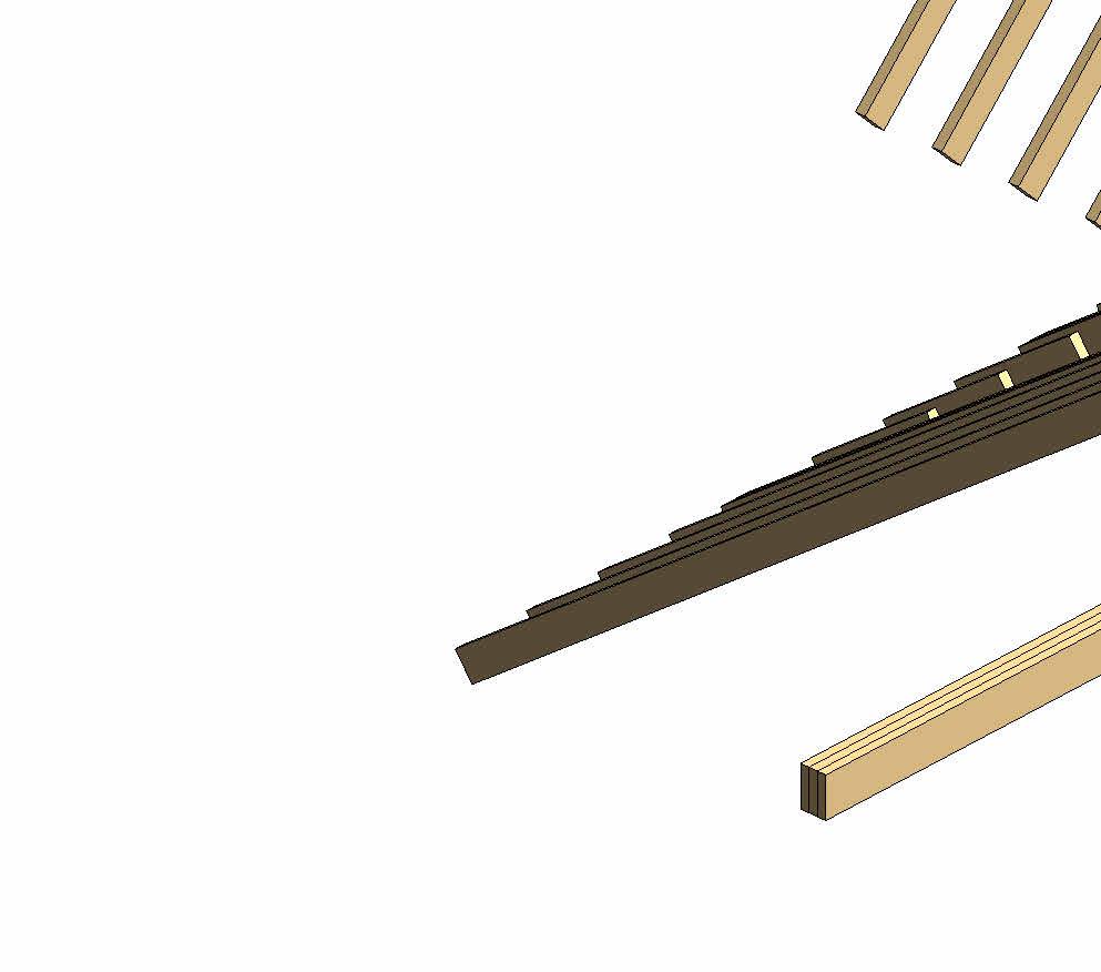

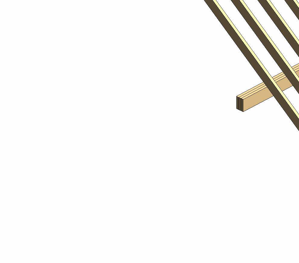
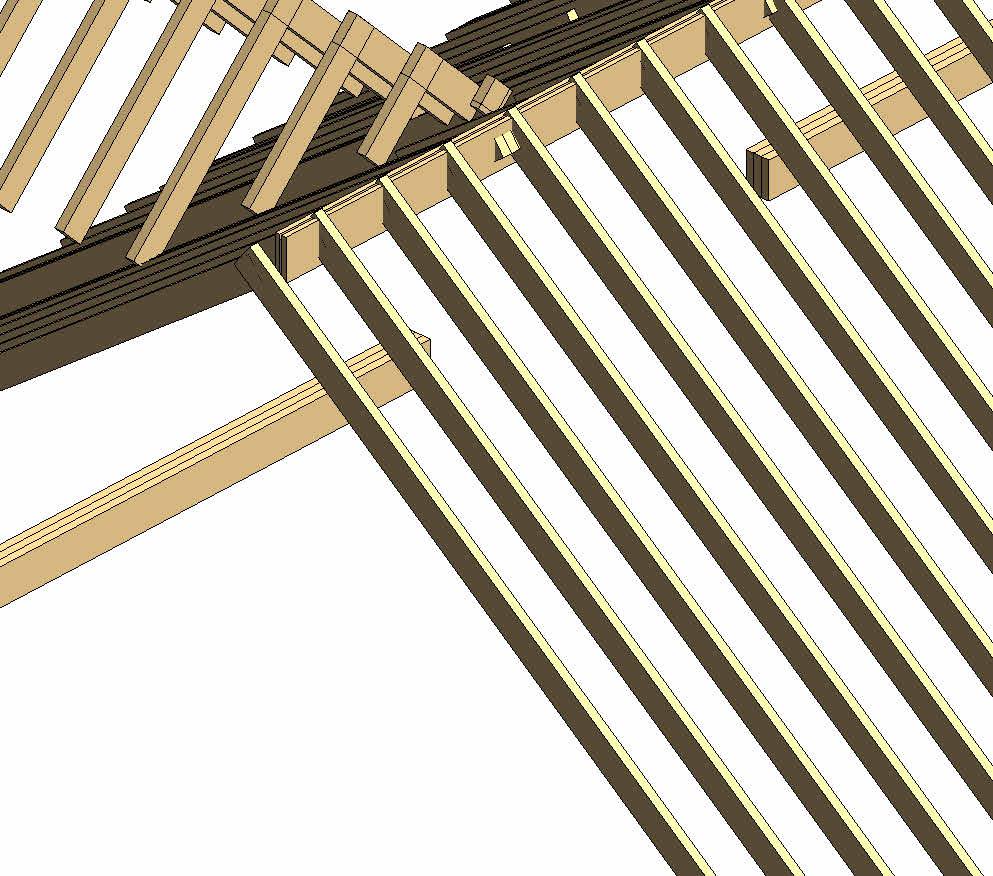
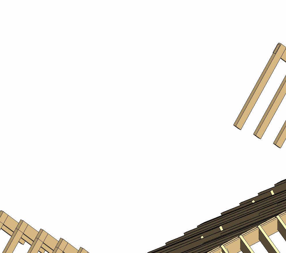
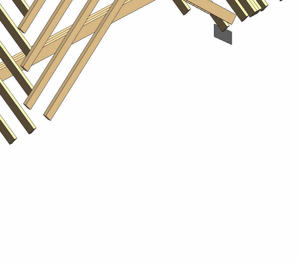
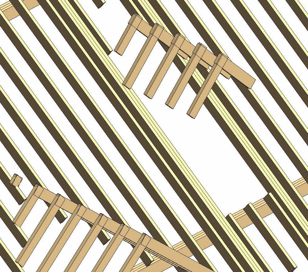
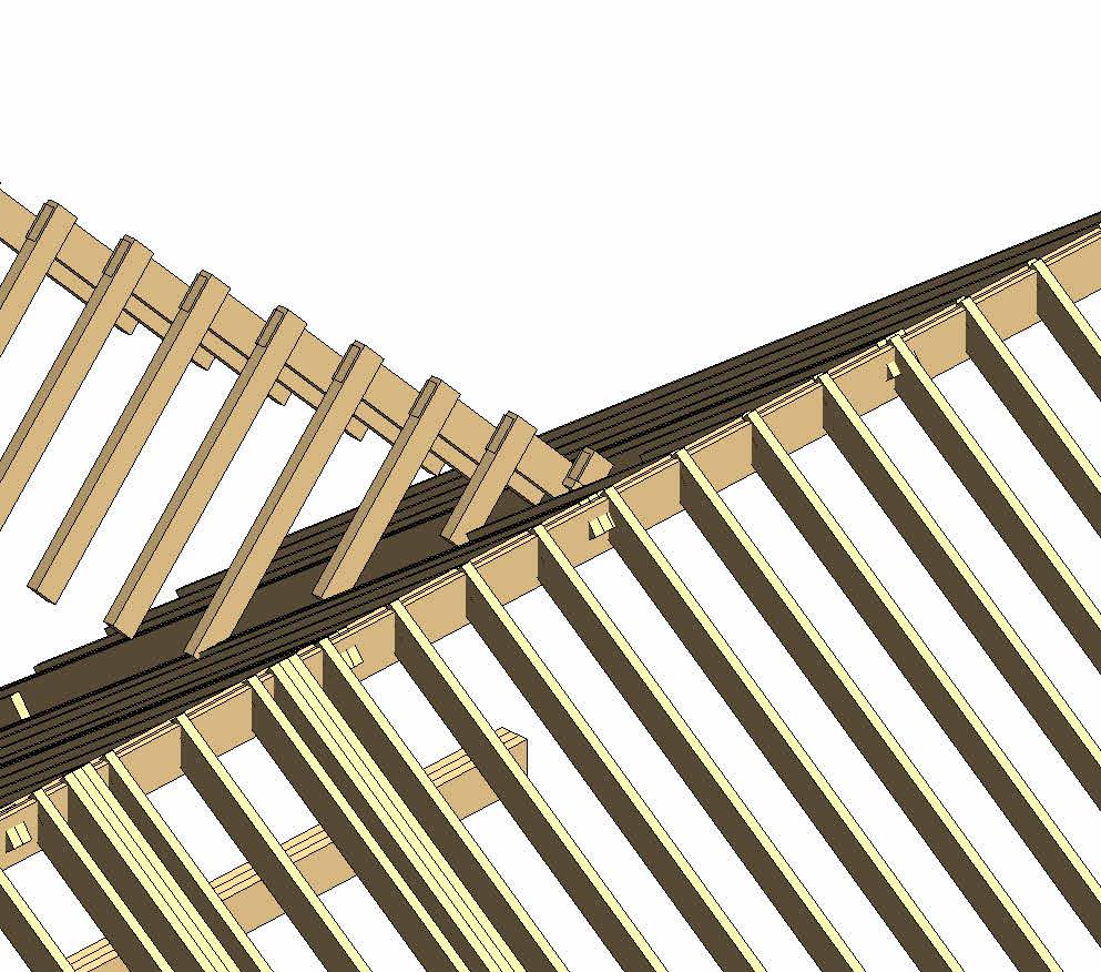
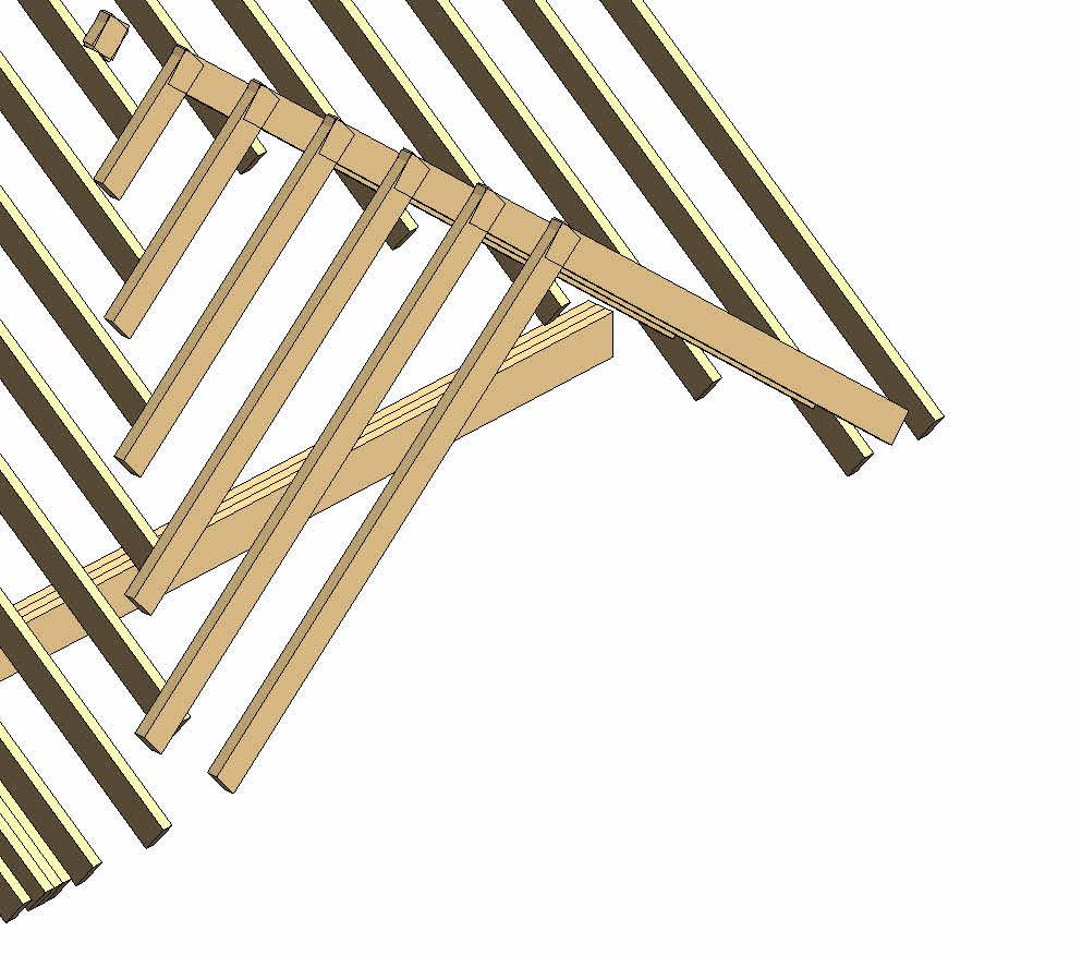

3 x 50 x150 Trimmers Note : Roof Trimmer Size 50 x 150mm @ 400mm C/C 1 A 1388 1906 1061 3 x 50 x 150 Roof Trimmers 3 x 50 x 150 Roof Trimmers 3x50x150 Roof Trimmers trimmer to trimmer 1520 150 grid to trimmer 1106 grid line to alight with ridge centre gridline to dormer stud 4023 121 trimmer to trimmer 1521 150 1906 grid to trimmer 7499 trimmer to trimmer 1006 150 grid to trimmer 4537 gridline to dormer stud 4023 121 gridline to dormer stud 3210 Note : All Roof Rafter size to be 50x150mm C24 grade @ 400mm c/c 2 x 50 x 150 Roof Trimmers Gridline Align to internal face of chimney wall at second floor 100 trimmer to trimmer 1760 100 grid to trimmer 4231 153 468426140 182 wall tilts at an angle 90.38° © THIS DRAWING IS THE COPYRIGHT OF DESIGNLABS LONDON LTD (DLL). It shall not be in any way used or reproduced or construct without their prior written consent. Al dimensions are to be checked on site by client or contractor prior to commencing any work. Work only to figured dimensions. Any discrepancies are to be reported to the DLL in writing and DLL shall not take responsiblity for site failing to inform discrepancies. Project Drawing : Scale Date Rev Dwg No Status ARCHITECTURE / INTERIOR / MANAGEMENT / PLANNING T: 07870661614 / 07888831314 E: info@designlabslondon.com W: www.designlabslondon.com DESIGNLABS LONDON 1 50 1 Roof Trimmer Setting Out Plan and 3D 11 Ennerdale Road. Richmond. TW9 3PG NC-GR2-DR-02-022.115/07/2022 Construction Roof Trimmer 3D1 1 : 50 Roof Trimmers Setting Out Plan2
Notes:
Rafter Direction Rafter Size 150x50mm C24 @400 Centers
DIMENSIONS IN
OTHERWISE SPECIFIED.
THE CONTRACTOR TO CHECK
DIMENSIONS, ANGLES, DRAIN RUNS AND CONDITIONS ON SITE BEFORE WORKS COMMENCEMENT. ANY DISCREPANCIES REPORT IMMEDIATELY TO THE ENGINEER.
CONDITION OF ALL EXISTING STRUCTURAL ELEMENTS, WITH PARTICULAR ATTENTION TO EXISTING BEARING WALLS TO BE USED FOR THE PROPOSED DEVELOPMENT, TO BE CHECKED BY THE CONTRACTOR BEFORE WORKS COMMENCEMENT.
4. DRAWINGS TO BE READ IN CONJUNCTION WITH RELATIVE STRUCTURAL CALCULATIONS, DETAILS AND SPECIFICATION.
5. DO NOT SCALE FROM DRAWINGS. DIMENSIONS ARE INDICATIVE ONLY.
6. CONTRACTOR AND CLIENT TO BE AWARE OF CONSTRUCTION & DESIGN MANAGEMENT (CDM) DUTIES.
DN 1 NC-GR2-DR-YY-034 NC-GR2-DR-XX-032 1 NC-GR2-DR-XX-032 NC-GR2-DR-XX-030 NC-GR2-DR-XX-031 NC-GR2-DR-XX-032 NC-GR2-DR-XX-033 WR01 Type SG WR02 Type SG Ridge Beam Flitch Beam New Flitch Beam 25 225mm with 12 200mm Mild Steel Plate 1 A 35.8° 37.8° 40° 40° 45° 45° 40° 40° 45° 45° 45°45° 3 x 50 x 150 Roof Trimmers 3 x 50 x 150 Roof Trimmers 3x50x150 Roof Trimmers grid line to alight with ridge centre 2 x 50 x 150 Roof Trimmers Gridline Align to internal face of chimney wall at second floor SYMBOL LEGEND Denotes Span of block on beam floor at ground floor level. Wall Types Tag- See drawing for Wall Types Door Type & Number- See Door Schedule for futher details Window Type & Number- See Window Schedule for futher details Electrical Meter Incoming Water Mains VFS Vertical Fire Stops DFS Stepped Fire Stops (to follow roof line) Joist Direction Joist sizes 220x50mm C24 @400 centers Double/Triple Trimmers sizes 2x200x50mm C24 Bolted @600 centers LEGEND Roof Slope Direction in Decimal Degree 1. ALL
MILLIMETERS UNLESS
2.
ALL
3.
© THIS DRAWING IS THE COPYRIGHT OF DESIGNLABS LONDON LTD (DLL). It shall not be in any way used or reproduced or construct without their prior written consent. Al dimensions are to be checked on site by client or contractor prior to commencing any work. Work only to figured dimensions. Any discrepancies are to be reported to the DLL in writing and DLL shall not take responsiblity for site failing to inform discrepancies. Project Drawing : Scale Date Rev Dwg No Status ARCHITECTURE / INTERIOR / MANAGEMENT / PLANNING T: 07870661614 / 07888831314 E: info@designlabslondon.com W: www.designlabslondon.com DESIGNLABS LONDON As indicated 3 Setting-Out Plans'Proposed Roof Floor Plan 11 Ennerdale Road. Richmond. TW9 3PG NC-GR2-DR-03-02315/07/2022 Construction 1 50 Proposed Roof Setting Out Plan1 0 SCALE 1: 1000800600400200200 mm25
Ground Floor 0 First Floor 3480 First Floor Ceiling 6330 Second Floor Ceiling 9000 Ground Floor Ceiling 3200 Basement Ceiling -240 0.1 Existing BasementFloor -2300 Loft 6600 Garden LVL -600 1 NC-GR2-DR-XX-032 2 NC-GR2-DR-XX-033 250 2401 2350 950 1250 3480 3860 2300 Living + Kitchen + Dining G7 Pantry G9 Bedroom 3 7 Bathroom 13 Bedroom 2 12 Study G5 2 NC-GR2-DR-XX-032 1 NC-GR2-DR-XX-033 RF01 RF01 RF02 FL01 FL03 Bedroom 4 WS01 Type WE WF01 Type SH B2.20 UKC152x152x37 220 2455 Top of Brickwork 3755 B1.12 UKC152x152x37 B1.18 UKC152x152x37 433 6 NC-GR2-DR-YY-038 8 NC-GR2-DR-YY-038 Level theshold B1.16A (Twin Beam) UKB152x89x16 possible location of new beams due to widening of opening- SE to confirm 0.1 Proposed Basement -3300 Ridge Beam Flitch Beam New Flitch Beam 25 x 225mm with 12 x 200mm Mild Steel Plate Triple Trimmer 50 x 200mm Triple Trimmer 50 200mm FL04 Sump Pit 1000x1000mm 1 2919 132 137 132 3203 F7. D1. Type Dr-H G9. D1. Type Dr-N S2. D1. Type Dr-J G5. D1. Type Dr-F 250 1000 1000 © THIS DRAWING IS THE COPYRIGHT OF DESIGNLABS LONDON LTD (DLL). It shall not be in any way used or reproduced or construct without their prior written consent. Al dimensions are to be checked on site by client or contractor prior to commencing any work. Work only to figured dimensions. Any discrepancies are to be reported to the DLL in writing and DLL shall not take responsiblity for site failing to inform discrepancies. Project Drawing : Scale Date Rev Dwg No Status ARCHITECTURE / INTERIOR / MANAGEMENT / PLANNING T: 07870661614 / 07888831314 E: info@designlabslondon.com W: www.designlabslondon.com DESIGNLABS LONDON 1 50 3 Setting-Out Sections'Proposed Sections 11 Ennerdale Road. Richmond. TW9 3PG NC-GR2-DR-XX-03015/07/2022 Construction 1 : 50 Proposed Section A1 0 SCALE 1: 2.521.50.50.5 m50
Ground Floor 0 First Floor 3480 First Floor Ceiling 6330 Second Floor Ceiling 9000 Ground Floor Ceiling 3200 Basement Ceiling -240 0.1 Existing BasementFloor -2300 Loft 6600 Garden LVL -600 1 NC-GR2-DR-XX-032 2 NC-GR2-DR-XX-033 Living + Kitchen + Dining G7 Kids Room G6 Bedroom 1 10 Dressing 9 Ensuite 8 325 480 2700 300 3480 1250 950 2 NC-GR2-DR-XX-032NC-GR2-DR-XX-033 RF01 RF01 RF01 RF02 FL01 FL03 B1.11 UKC203x203x46 B1.10 UKC203x203x46 FL02 WS02 Type WE WG02 Type WA B2.21 UKC152x152x37 0.1 Proposed Basement -3300 1046 Ridge Beam Flitch Beam New Flitch Beam 25 x 225mm with 12 x 200mm Mild Steel Plate Triple Trimmer 50 x 200mm Triple Trimmer 50 x 200mm FL04 1609 3239 345 2955 560 478 8940 158425 1 2919 132137132 3203 G4. D2. Type Dr-E F4. D1. Type Dr-I © THIS DRAWING IS THE COPYRIGHT OF DESIGNLABS LONDON LTD (DLL). It shall not be in any way used or reproduced or construct without their prior written consent. Al dimensions are to be checked on site by client or contractor prior to commencing any work. Work only to figured dimensions. Any discrepancies are to be reported to the DLL in writing and DLL shall not take responsiblity for site failing to inform discrepancies. Project Drawing : Scale Date Rev Dwg No Status ARCHITECTURE / INTERIOR / MANAGEMENT / PLANNING T: 07870661614 / 07888831314 E: info@designlabslondon.com W: www.designlabslondon.com DESIGNLABS LONDON 1 50 3 Setting-Out Sections'Proposed Sections 11 Ennerdale Road. Richmond. TW9 3PG NC-GR2-DR-XX-03115/07/2022 Construction 0 SCALE 1: 2.51.510.50.5 m50 1 : 50 Proposed Section B1
Ground Floor 0 First Floor 3480 First Floor Ceiling 6330 Second Floor Ceiling 9000 Ground Floor Ceiling 3200 Basement Ceiling -240 0.1 Existing BasementFloor -2300 Loft 6600 Garden LVL -600 1 NC-GR2-DR-YY-034 1250 950 1 NC-GR2-DR-XX-030NC-GR2-DR-XX-031 2200 1280 2200 1280 2700 3480 50100 1783 1406 950 1250 1783 1406 FL01 RF02 RF02 WS02 Type WE WR02 Type SG WR01 Type SG WS01 Type WE RF01 RF01 3214 3000 B1.13 UKC203x203x86 Top of Brickwork 3750 Top of Brickwork 3750 0.1 Proposed Basement -3300 1000 2955 1000 FL04 R @4 200.0 mm 1900 1 NC-GR2-DR-YY-040 Sump Pit 1000x1000mm 478 7351 478 1351 A 6700 G7. D1. Type Dr-N G9. D1. Type Dr-N G4. D1. Type Dr-D Ground Floor 0 First Floor 3480 First Floor Ceiling 6330 Second Floor Ceiling 9000 Ground Floor Ceiling 3200 Basement Ceiling -240 0.1 Existing BasementFloor -2300 Loft 6600 Garden LVL -600 1 NC-GR2-DR-YY-034 1 NC-GR2-DR-XX-030 1 NC-GR2-DR-XX-031 1280 0 2200 1280 2200 Kids Room G6 Hallway G2 Study G5 Bedroom 2 12 Bedroom 1 10 3130 B1.01 UB152x89x16 WS03 TypeB82 A © THIS DRAWING IS THE COPYRIGHT OF DESIGNLABS LONDON LTD (DLL). It shall not be in any way used or reproduced or construct without their prior written consent. Al dimensions are to be checked on site by client or contractor prior to commencing any work. Work only to figured dimensions. Any discrepancies are to be reported to the DLL in writing and DLL shall not take responsiblity for site failing to inform discrepancies. Project Drawing : Scale Date Rev Dwg No Status ARCHITECTURE / INTERIOR / MANAGEMENT / PLANNING T: 07870661614 / 07888831314 E: info@designlabslondon.com W: www.designlabslondon.com DESIGNLABS LONDON 1 50 2 Setting-Out Sections'Proposed Sections 11 Ennerdale Road. Richmond. TW9 3PG NC-GR2-DR-XX-03215/07/2022 Construction 0 SCALE 1: 2.521.50.50.5 m50 1 : 50 Proposed Section C1 1 : 50 Proposed Section D2
Ground Floor 0 First Floor 3480 First Floor Ceiling 6330 Second Floor Ceiling 9000 Ground Floor Ceiling 3200 Basement Ceiling -240 0.1 Existing BasementFloor -2300 Loft 6600 Garden LVL -600 1 NC-GR2-DR-YY-034 1 NC-GR2-DR-XX-030 1 NC-GR2-DR-XX-031 1783 2104 1783 Ensuite 8 Hallway 14 Bedroom 3 7 Hallway G2 Pantry G9 RF01 RF01 FL03 FL02 B1.15 UB203x102x23 5 NC-GR2-DR-YY-038 7 NC-GR2-DR-YY-038 WR02 Type SG WR01 Type SG Wall Foundation Bearing Footing 900x600mm 640 3774 31 799 A 4044 6326 B1.16 UB305x127x48 F8. D1. Type Dr-H G3. D1. Type Dr-B G2. D2. Type Dr-B G10. TypeD1.Dr-X Ground Floor 0 First Floor 3480Ground Floor Ceiling 3200 Basement Ceiling -240 0.1 Existing BasementFloor -2300 Garden LVL -600 1 NC-GR2-DR-XX-031 RF02 FL01 Top of Brickwork 2200 Top of Brickwork 3750 0.1 Proposed Basement -3300 EXW-31 G4. D3. Type Dr-D EXW-32 © THIS DRAWING IS THE COPYRIGHT OF DESIGNLABS LONDON LTD (DLL). It shall not be in any way used or reproduced or construct without their prior written consent. Al dimensions are to be checked on site by client or contractor prior to commencing any work. Work only to figured dimensions. Any discrepancies are to be reported to the DLL in writing and DLL shall not take responsiblity for site failing to inform discrepancies. Project Drawing : Scale Date Rev Dwg No Status ARCHITECTURE / INTERIOR / MANAGEMENT / PLANNING T: 07870661614 / 07888831314 E: info@designlabslondon.com W: www.designlabslondon.com DESIGNLABS LONDON 1 50 2 Setting-Out Sections'Proposed Sections 11 Ennerdale Road. Richmond. TW9 3PG NC-GR2-DR-XX-03315/07/2022 Construction 1 : 50 Proposed Section E1 1 : 50 Proposed Section F2
Ground Floor 0 First Floor 3480 First Floor Ceiling 6330 Second Floor Ceiling 9000 Ground Floor Ceiling 3200 Basement Ceiling -240 0.1 Existing BasementFloor -2300 Loft 6600 Garden LVL -600 1 NC-GR2-DR-XX-032 2 NC-GR2-DR-XX-033 NC-GR2-DR-XX-032 1 NC-GR2-DR-XX-033 0.1 Proposed Basement -3300 FL04 FL01 FL01 WF02 Type SI B1.11 UKC203x203x46 B1.14B UKB152x89x16 B1.14A UKB152x89x16 B1.14C UKB152x89x16 B1.10 UKC203x203x46 TypeB66 Ridge Beam Flitch Beam New Flitch Beam 25 225mm with 12 200mm Mild Steel Plate Triple Trimmer 50 200mm R @4 200.0 mm 1 2919 132 920 S3. D1. Type Dr-J F2. D1. Type Dr-H F5. D1. Type Dr-B G2. D3. Type Dr-C G7. D1. Type Dr-N © THIS DRAWING IS THE COPYRIGHT OF DESIGNLABS LONDON LTD (DLL). It shall not be in any way used or reproduced or construct without their prior written consent. Al dimensions are to be checked on site by client or contractor prior to commencing any work. Work only to figured dimensions. Any discrepancies are to be reported to the DLL in writing and DLL shall not take responsiblity for site failing to inform discrepancies. Project Drawing : Scale Date Rev Dwg No Status ARCHITECTURE / INTERIOR / MANAGEMENT / PLANNING T: 07870661614 / 07888831314 E: info@designlabslondon.com W: www.designlabslondon.com DESIGNLABS LONDON 1 50 1 Setting-Out Sections'Proposed Sections 11 Ennerdale Road. Richmond. TW9 3PG NC-GR2-DR-YY-03415/07/2022 Construction 1 : 50 Section 251
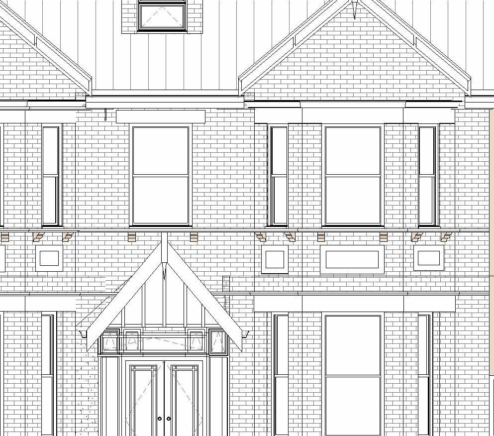
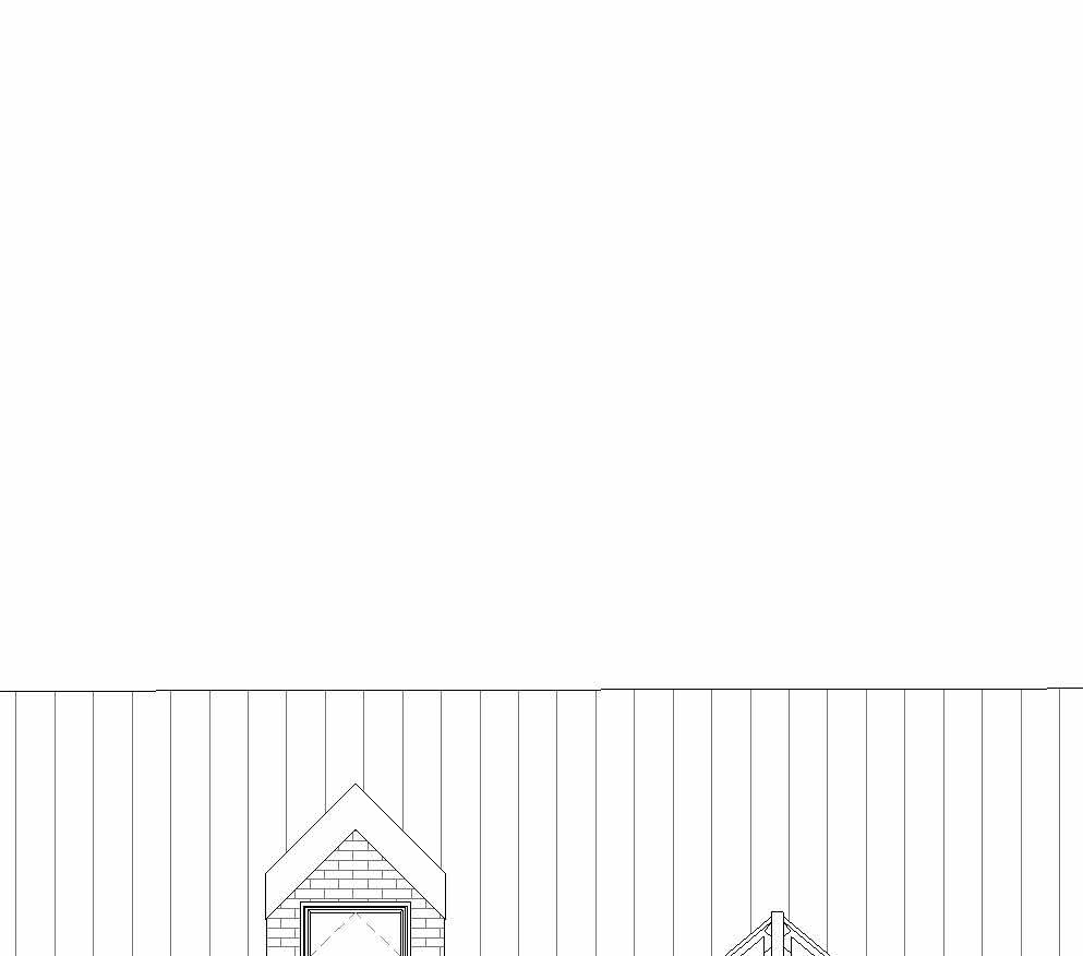

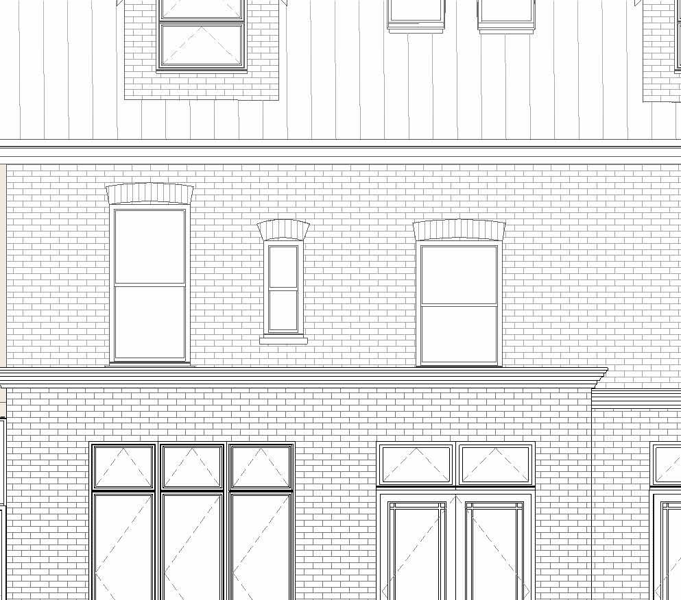
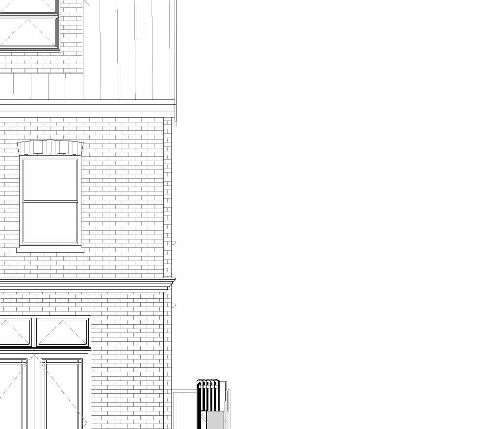
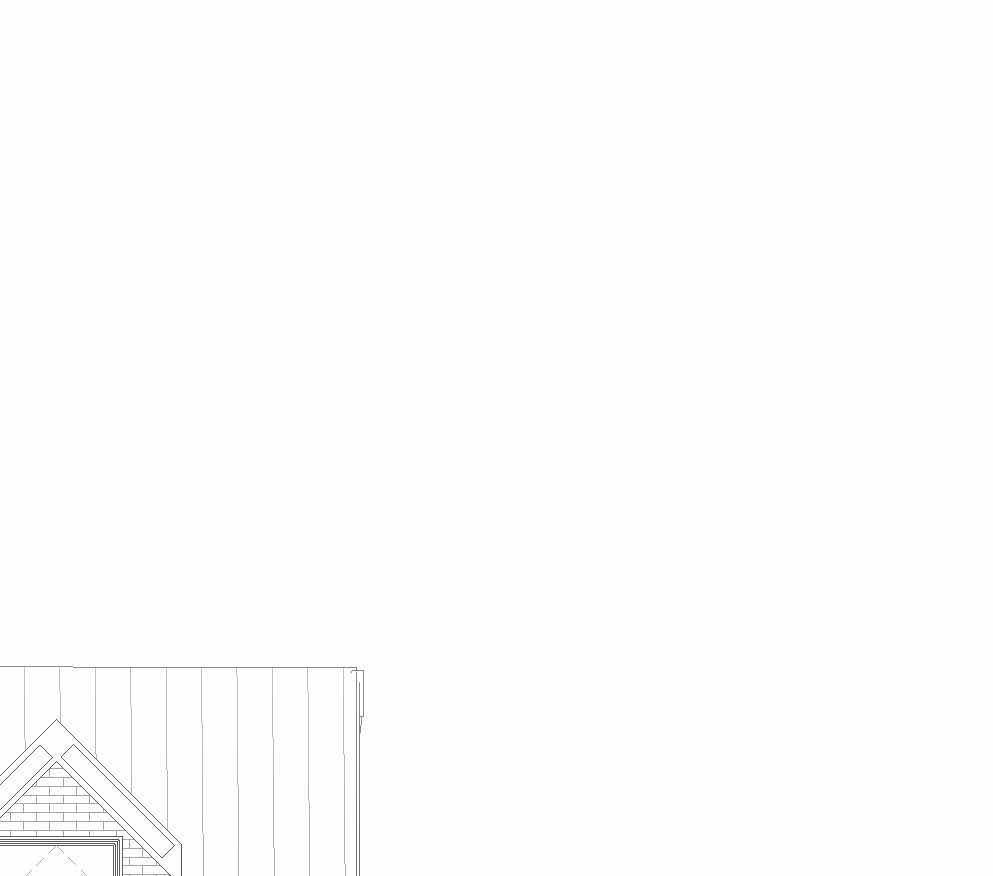
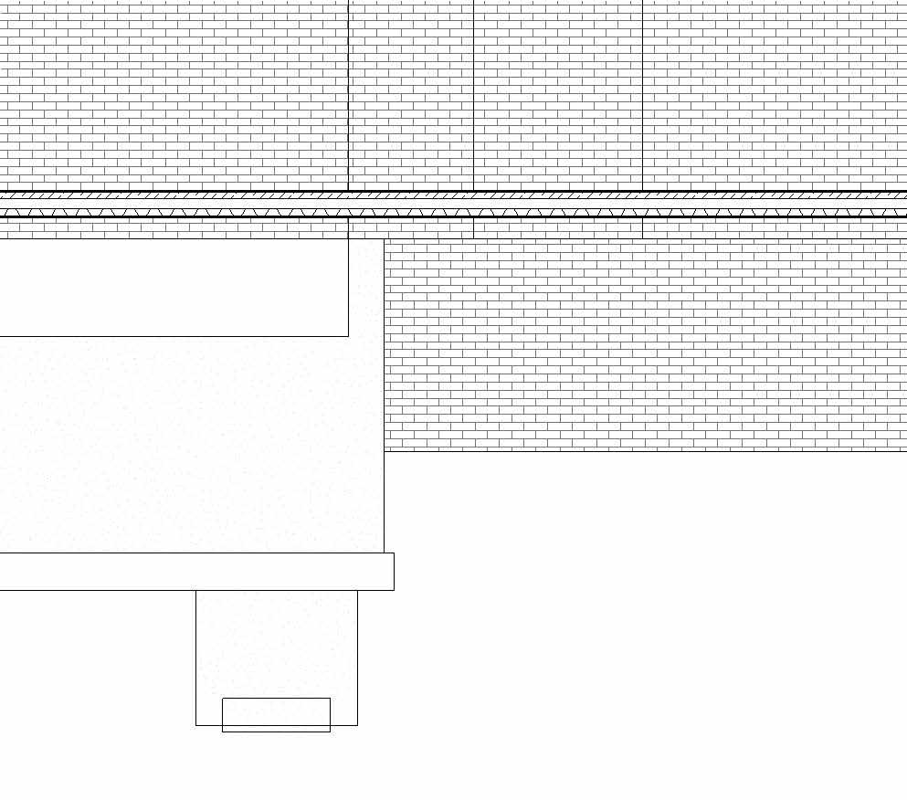
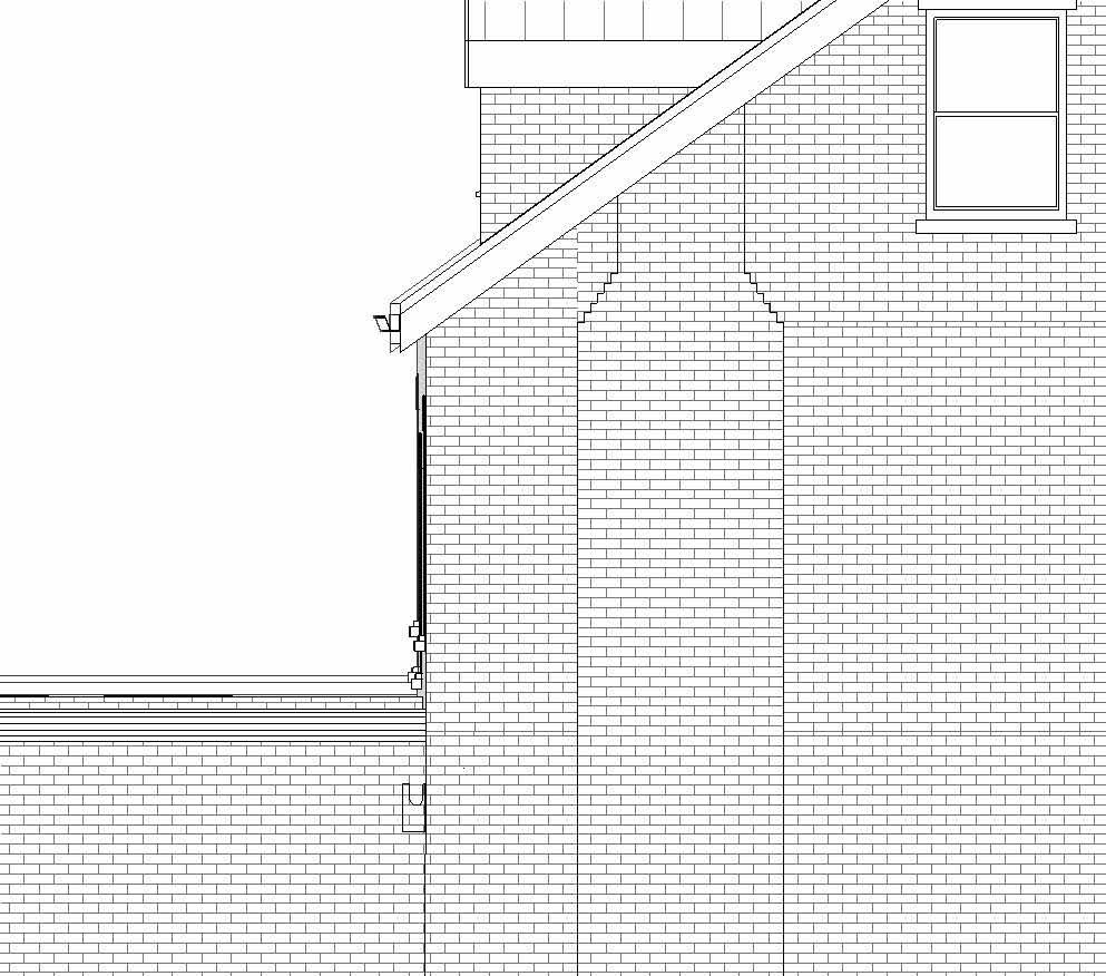
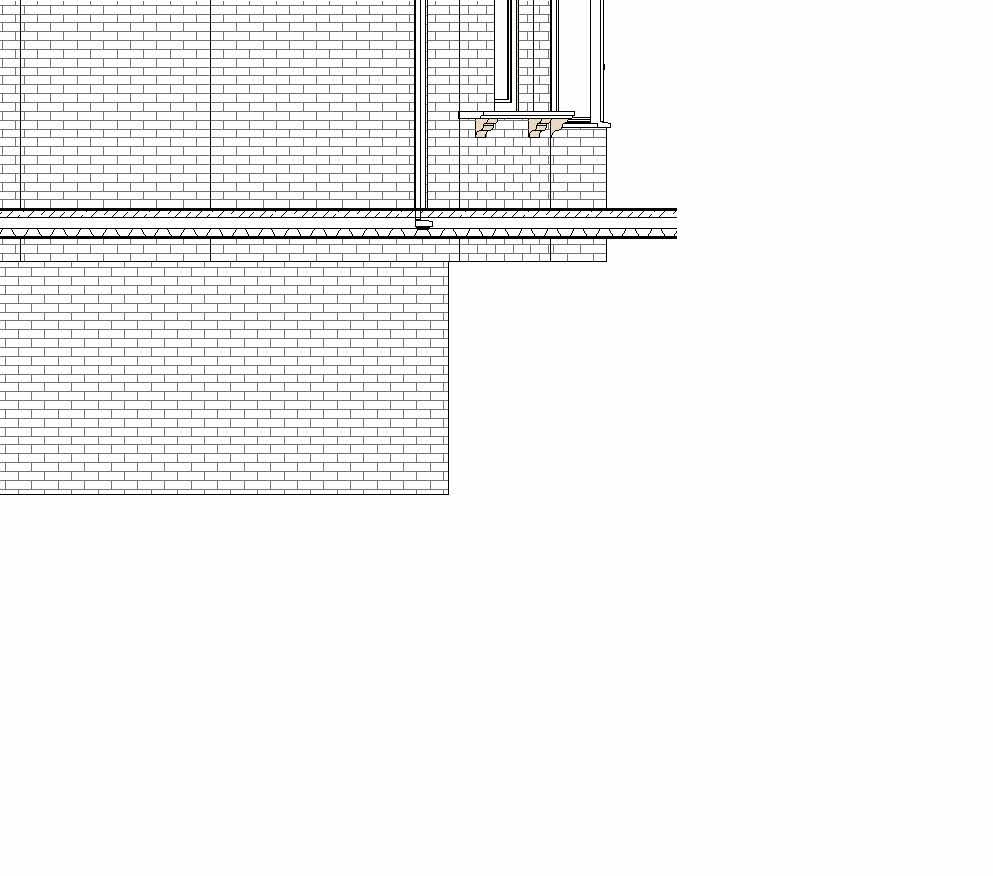
Ground Floor 0 First Floor 3480 First Floor Ceiling 6330 Second Floor Ceiling 9000 Ground Floor Ceiling 3200 Basement Ceiling -240 0.1 Existing BasementFloor -2300 Loft 6600 Garden LVL -600 1000 1000 1054 1863 0.1 Proposed Basement -3300 WS03 TypeB82 Sump Pit 1000x1000mm 210 350 1000 250 1500230 G4. D1. Type Dr-D Ground Floor 0 First Floor 3480 First Floor Ceiling 6330 Second Floor Ceiling 9000 Ground Floor Ceiling 3200 Basement Ceiling -240 0.1 Existing BasementFloor -2300 Loft 6600 Garden LVL -600 2400 600 2401 600 300 2700 2200 0 1280 2200 1280 3480 50 950 1250 1783 1406 950 1250 1783 1406 WS02 Type WE WR02 Type SG WR01 Type SG WS01 Type WE Underside Threshold -55 Underside Threshold -55 0.1 Proposed Basement -3300 WG02 Type WA WG01 Type WA WG03 Type WA Sump Manhole 750x750 DG01 TypeDA DG02 TypeDAG4. D3. Type Dr-D WG04 Type WB WG05 Type WB WG06 Type WB WG07 Type WB © THIS DRAWING IS THE COPYRIGHT OF DESIGNLABS LONDON LTD (DLL). It shall not be in any way used or reproduced or construct without their prior written consent. Al dimensions are to be checked on site by client or contractor prior to commencing any work. Work only to figured dimensions. Any discrepancies are to be reported to the DLL in writing and DLL shall not take responsiblity for site failing to inform discrepancies. Project Drawing : Scale Date Rev Dwg No Status ARCHITECTURE / INTERIOR / MANAGEMENT / PLANNING T: 07870661614 / 07888831314 E: info@designlabslondon.com W: www.designlabslondon.com DESIGNLABS LONDON 1 50 2 Setting-Out Elevations'Proposed Elevations 11 Ennerdale Road. Richmond. TW9 3PG NC-GR2-DR-YY-03515/07/2022 Construction 1 : 50 Proposed Front Elevation1 1 : 50 Proposed Rear Elevation2 0 SCALE 1: 2.521.510.50.5 m50
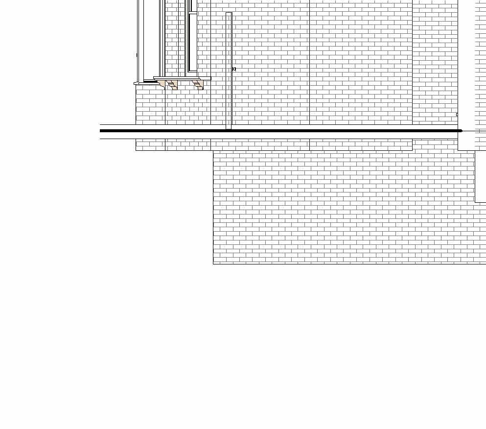
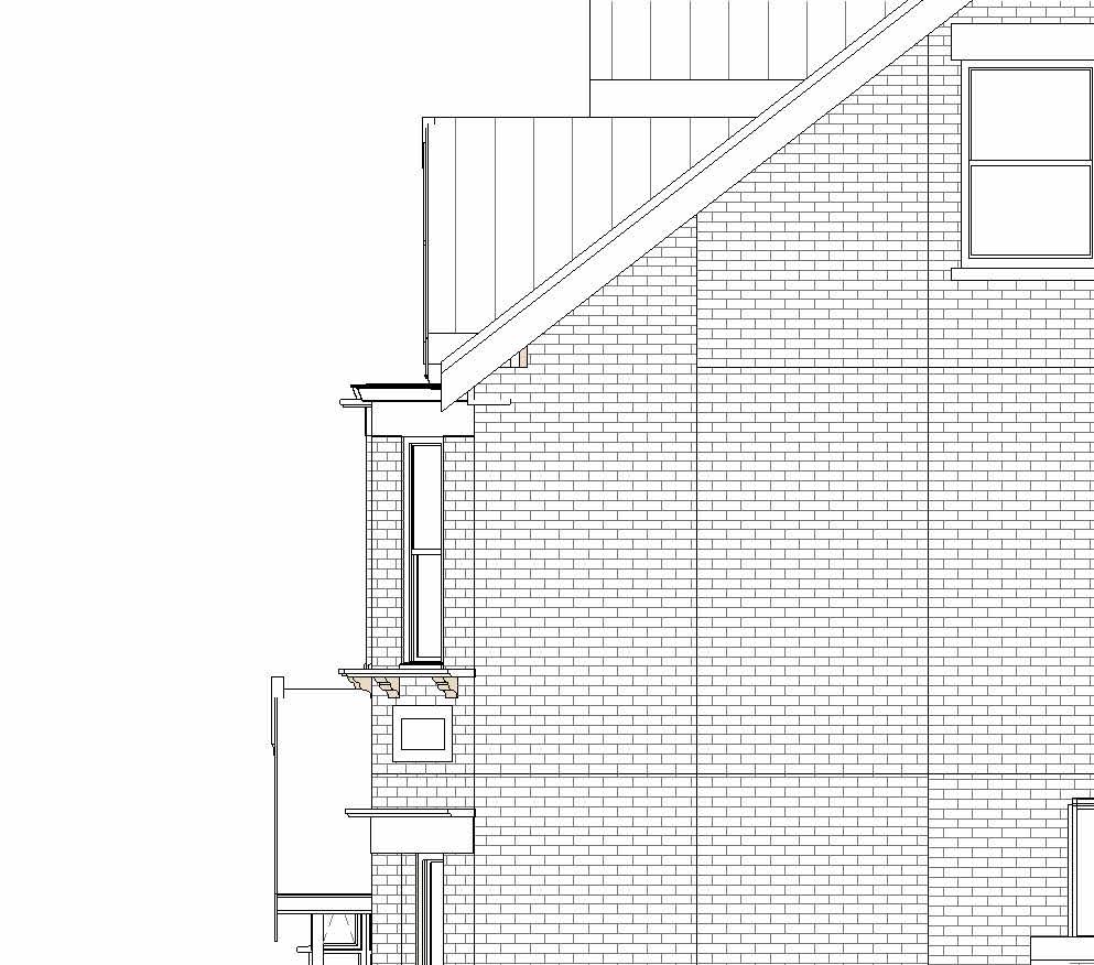
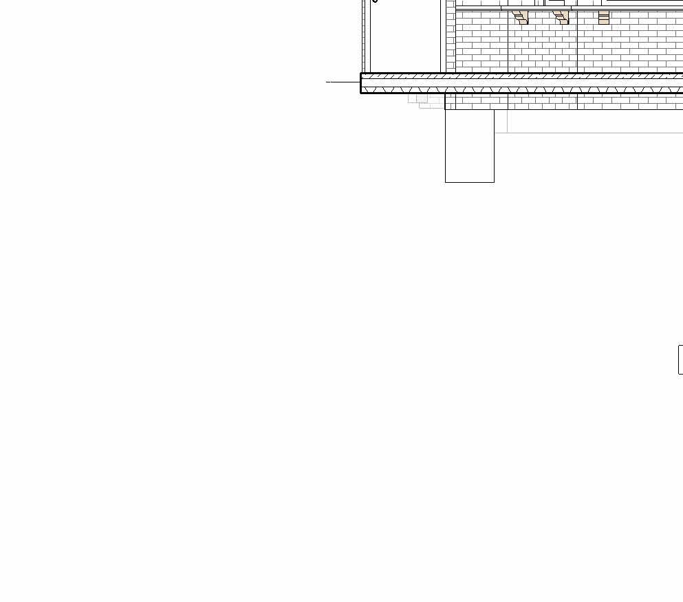
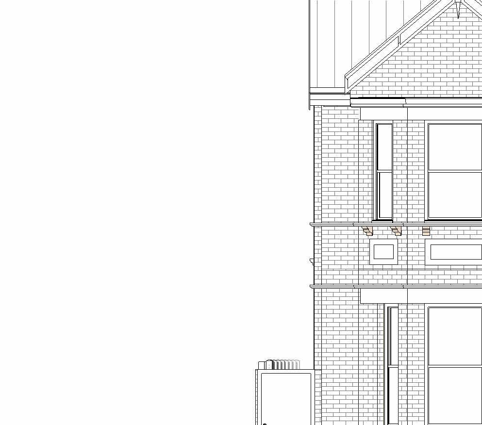
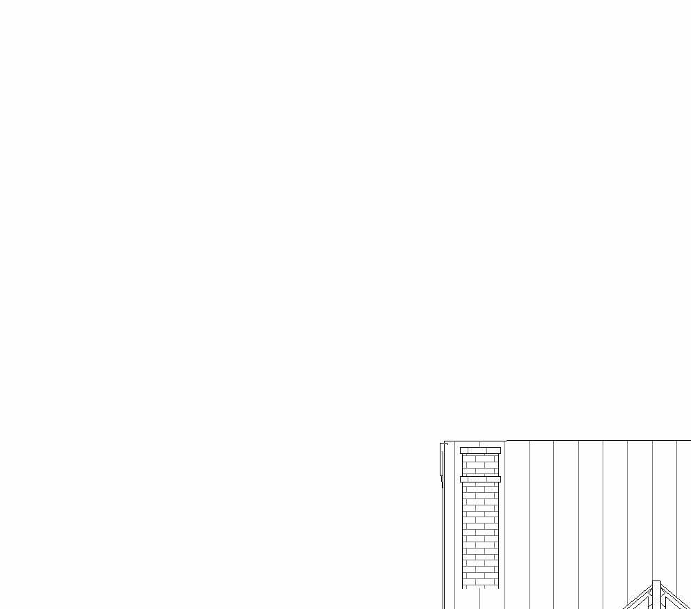
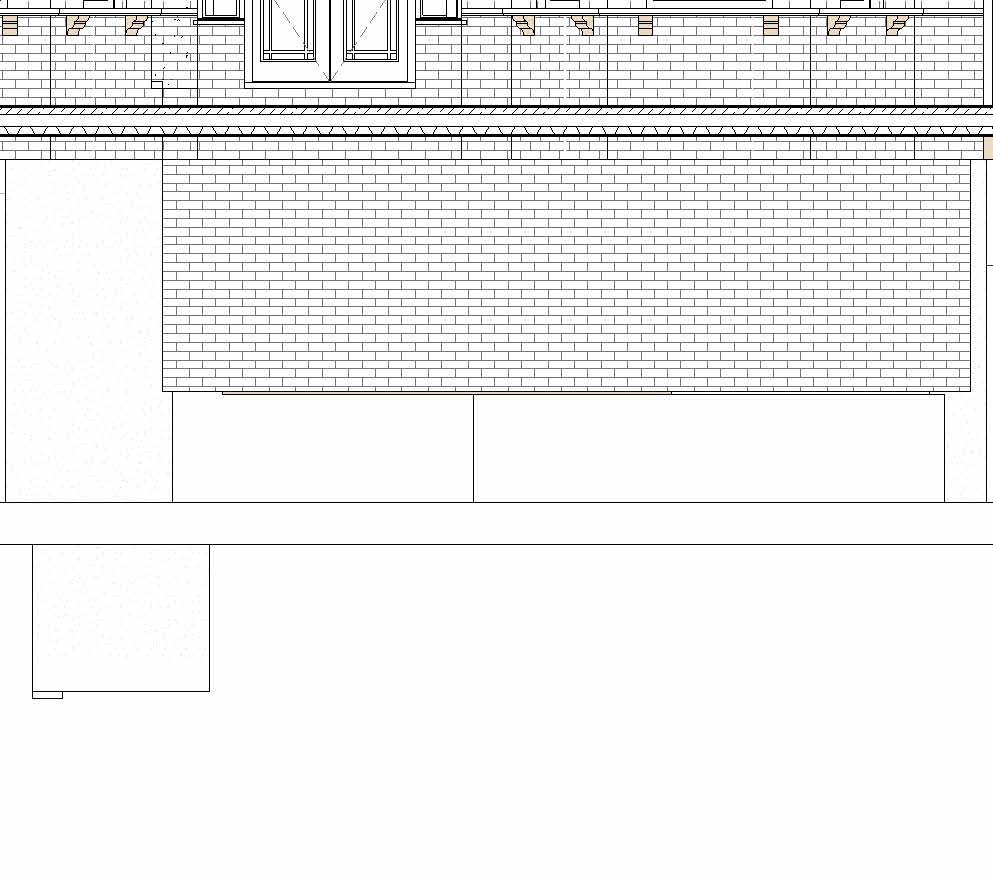
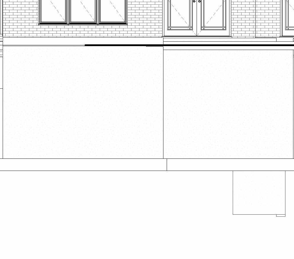
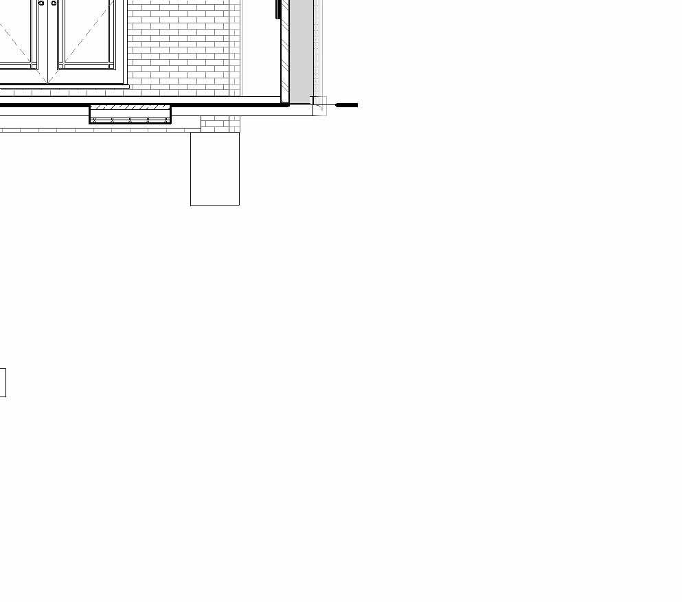
Ground Floor 0 First Floor 3480 First Floor Ceiling 6330 Second Floor Ceiling 9000 Ground Floor Ceiling 3200 Basement Ceiling -240 3200 3200 0.1 Existing BasementFloor -2300 Loft 6600 Garden LVL -600 1280 2200 1406 1783 270 3480 0.1 Proposed Basement -3300 Sump MAnhole 750x750 0 1250 350 210 1800 1260 2290 180 976 Wall Foundation Bearing Footing900x600mm 4870 © THIS DRAWING IS THE COPYRIGHT OF DESIGNLABS LONDON LTD (DLL). It shall not be in any way used or reproduced or construct without their prior written consent. Al dimensions are to be checked on site by client or contractor prior to commencing any work. Work only to figured dimensions. Any discrepancies are to be reported to the DLL in writing and DLL shall not take responsiblity for site failing to inform discrepancies. Project Drawing : Scale Date Rev Dwg No Status ARCHITECTURE / INTERIOR / MANAGEMENT / PLANNING T: 07870661614 / 07888831314 E: info@designlabslondon.com W: www.designlabslondon.com DESIGNLABS LONDON 1 50 1 Setting-Out Elevations'Proposed Elevations 11 Ennerdale Road. Richmond. TW9 3PG NC-GR2-DR-YY-03615/07/2022 Construction 1 : 50 Proosed RHS Elevation 2 0 SCALE 1: 2.521.50.50.5 m50
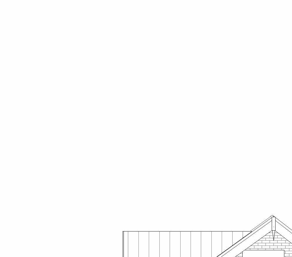
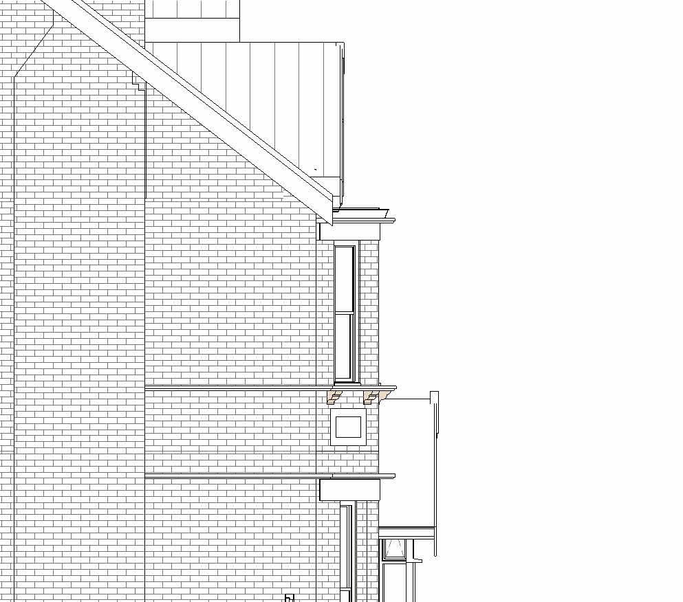
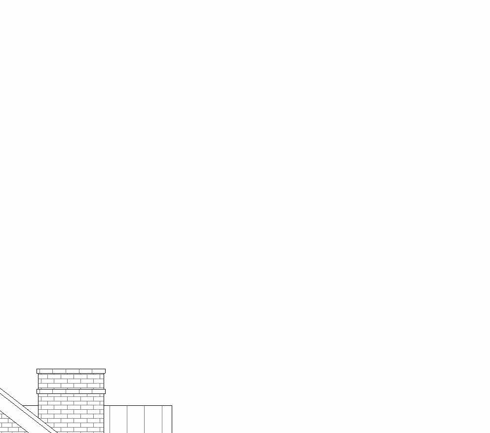
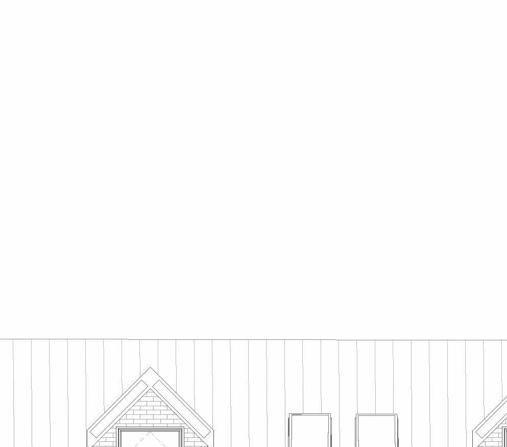
Ground Floor 0 First Floor 3480 First Floor Ceiling 6330 Second Floor Ceiling 9000 Ground Floor Ceiling 3200 Basement Ceiling -240 0.1 Existing BasementFloor -2300 Loft 6600 Garden LVL -600 3480 1406 0.1 Proposed Basement -3300 © THIS DRAWING IS THE COPYRIGHT OF DESIGNLABS LONDON LTD (DLL). It shall not be in any way used or reproduced or construct without their prior written consent. Al dimensions are to be checked on site by client or contractor prior to commencing any work. Work only to figured dimensions. Any discrepancies are to be reported to the DLL in writing and DLL shall not take responsiblity for site failing to inform discrepancies. Project Drawing : Scale Date Rev Dwg No Status ARCHITECTURE / INTERIOR / MANAGEMENT / PLANNING T: 07870661614 / 07888831314 E: info@designlabslondon.com W: www.designlabslondon.com DESIGNLABS LONDON 1 50 1 Setting-Out Elevations'Proposed Elevations 11 Ennerdale Road. Richmond. TW9 3PG NC-GR2-DR-YY-03715/07/2022 Construction 1 50 Proposed LHS Elevation1
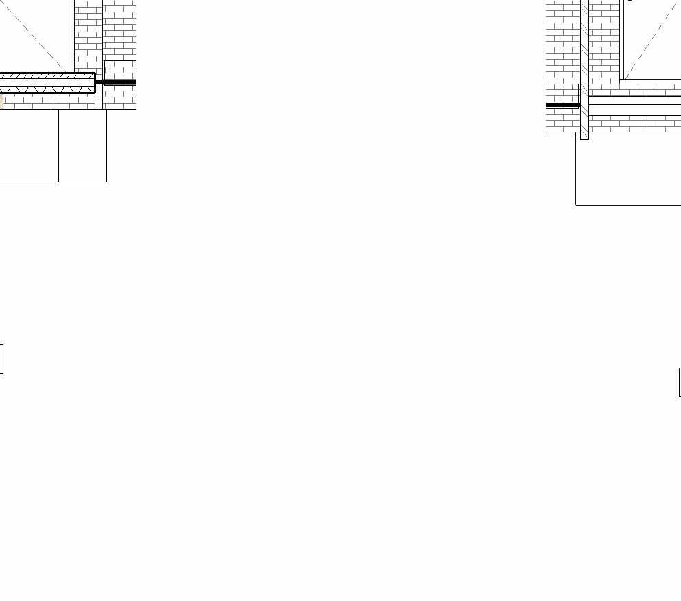
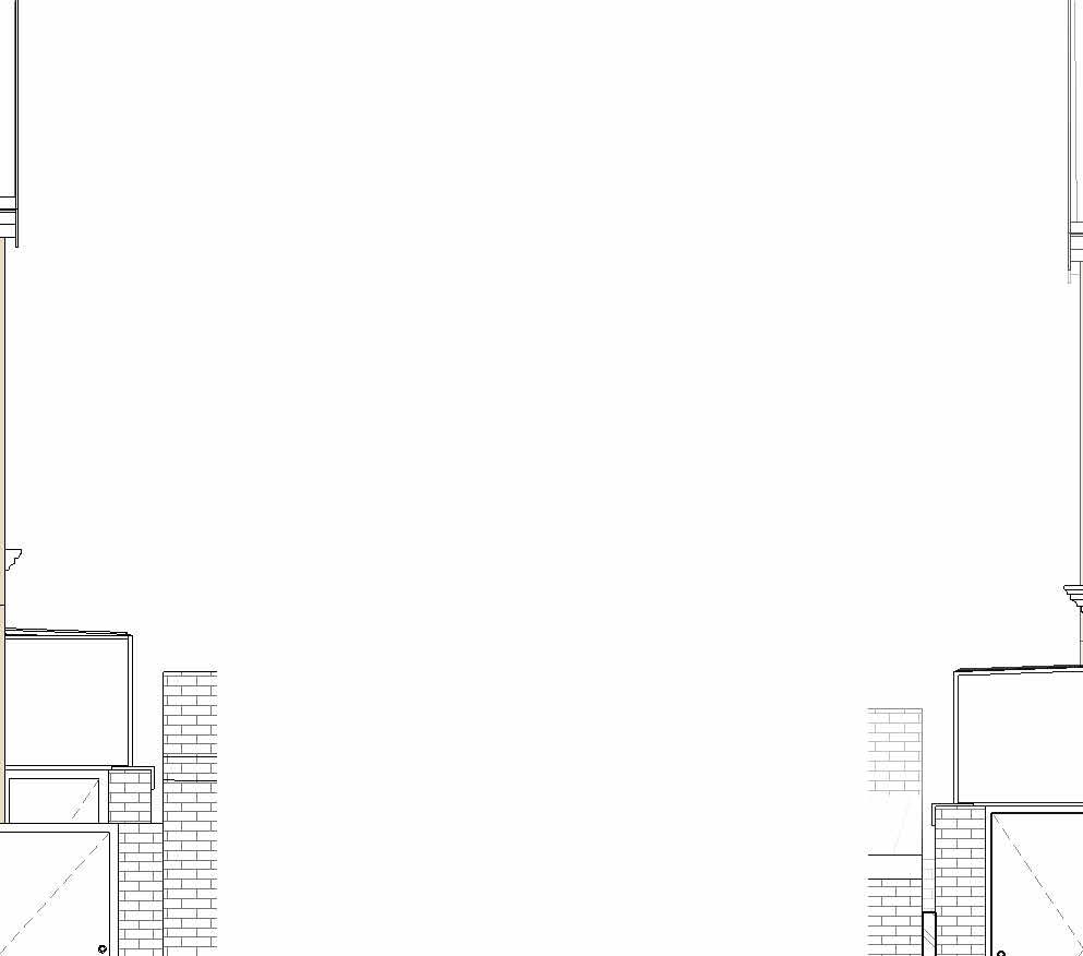
Rear dormer window sole plate "insert" into existing roof structure with window opening Drawing note: this is a typical dormer window detail were the dormer is required to be positioned up the existing roof slope as mentioned on drawing number LC14A. any new timber or steel beams will need to be carefully designed & detailed by structural engineer to take account of impose & superimposed (live & dead) loads from snow wind, roof & floor new floor joists built in alongside the existing ceiling joists as drawing number LC02 supported off galvanised mild steel joist hangers insulated stud wall dormer cheek as built-up off floor board, structure to be approved by structural engineer grey line indicates underside of sloped ceiling caulking finish to window board skim junction lead flashing, suitable non-toxic alternative or use pre-formed drip cill to suit chosen dormer cheek external wall finish finish counterbatten to allow breather membrane to dress over tilting fillet & allow any excess driven rainwater to escape the construction possible location of ventilation gap with insect mesh New pasterboard ceiling to be lower as required to cover steel beam (if any). Use 15mm thick FR p/b underside any steel beam. Use 15mm SoundBloc P/b else where. Finish ceiling p/b in 2.5 mm skim coat. Soffit and facia materials to be confirmed by client see Sheet NC-GR2-DR-XX-030 For distance refer to Section A FastClad system fixed to treated 50x50mm vertical battens or galvanised steel framing at max 400mm centres 950 105 25 13177 30 22 20 122 15 23 Double Layer of 15mm Sound Block Plaster Board new roofing Slates on tiling battens and counter battens on breathable roofing membrane. batten size 25 x 38mm min. all to BS 5534: 2014 & BS 5250: 2011 Dormer pitched roof eaves detail with gutter Drawing note: this is a typical dormer head eaves detail; note that the counterbatten should be tightly fixed upto the underside of the insulation as an active barrier against vermin & that the insulation in the roof should partially overlap the insulation in the wall construction to ensure no cold bridging occurs. insulated stud wall down to floor level as dormer window head detail. U-value not to exceed 0.28W /m²K Downstand in soffit board material Slate tiles on 25 38mm treated sw tiling battens at centres to suit chosen tile as specified by manufacturer rafters birdsmouthed over head plate top plate timbers that are sized as the dormer cheek to be approved by structural engineer insulation shown between & under the rafters to form a "warm" roof as detail number LC05 for a new build, this can be formed as a warm or cold roof, & with rafter or ceiling level insulation to form a flat or sloping ceiling 70 Soffit and facia materials to be confirmed by client 10 FastClad system fixed to treated 50x50mm vertical battens or galvanised steel framing at max 400mm centres Timber noggin (not continuous) Maintain minimum 10mm ventilation gap. Treated timber or UPYC fascia and vented soffit with downstand. Aluminium or Plastic rain water gutter. end tile to project 50mm min. into the gutter & underlay dressed into the gutter 31 121 15 27 30 150 33 Main Ridge Detail new roofing Slates on tiling battens and counter battens on breathable roofing membrane. batten size 25 x 38mm min. all to BS 5534: 2014 & BS 5250: 2011 High performance PIR insulation board fitted between the rafters (& underdrawn with a thicker amount of the same board?) with vapour control layer. Ensure insulation is pressed-up tight to underside of rafters.Typical overall thickness is 125mm dependent on the thermal resistance value of the insulation used. U-value not to exceed 0.16W /m²K New Flitch Beam 25x 225mm With 12x 200mm Mild Steel Plate Double Layers of 15mm SoundBlock Plasterboard 25 12 25 151 41 30 Dormer window head detail Drawing note: this is a typical dormer window head detail with a sloped ceiling to allow for the greatest floor to ceiling height, comfortable finished floor to ceiling height around 2.3m, see detail LC13A for section running through the dormer cheeks. one important part of the detail is the tilting fillet at the ead ensure there is enough angle & gap to allow any excess driven rainwater to escape the construction otherwise this will lead to premature rotting of the structure. VCL nailed or stapled to back of timber studs insulated stud wall dormer cheek; up to top of ceiling level insulation use 120mm thick stud filled with PIR insulation board or 75mm thick stud filled with PIR insulation board & finished internally with 25mm thick PIR insulation board with 12.5mm thick plasterboard with 3mm thick skim coat finish. U-value not to exceed 0.28W /m²K breather membrane with 0.6MNs/g min. vapour resistance to BS EN 13859-1 2: 2010 & 100mm min. horizontal joint laps & 150mm min. vertical joint laps fixed to plywood sheathing 12mm cementitious board or marine grade plywood finish counter batten to allow breather membrane to dress over tilting fillet & allow any excess driven rainwater to escape the construction underdraw tilting fillet with insect mesh at ventialation gap doubled-up timber studs as head trimmers to window; confirm larger window door spans with structural engineer timber windows or suitable alternative U-value not to exceed 1.4 W/m²K and G-value not to exceed 0.63 FastClad system fixed to treated 50x50mm vertical battens or galvanised steel framing at max 400mm centres 30 26 16 122 32 32 100 Double Layer of 15mm Sound Block Plasterboard © THIS DRAWING IS THE COPYRIGHT OF DESIGNLABS LONDON LTD (DLL). It shall not be in any way used or reproduced or construct without their prior written consent. Al dimensions are to be checked on site by client or contractor prior to commencing any work. Work only to figured dimensions. Any discrepancies are to be reported to the DLL in writing and DLL shall not take responsiblity for site failing to inform discrepancies. Project Drawing : Scale Date Rev Dwg No Status ARCHITECTURE / INTERIOR / MANAGEMENT / PLANNING T: 07870661614 / 07888831314 E: info@designlabslondon.com W: www.designlabslondon.com DESIGNLABS LONDON 1 10 1 Setting-Out Sections'Proposed Detail Callout 11 Ennerdale Road. Richmond. TW9 3PG NC-GR2-DR-YY-03815/07/2022 Construction 1 : 10 Rear dormer window base detail6 1 : 10 Dormer Window Pitched Roof Eaves Detail5 1 : 10 Main Ridge Detail7 1 : 10 Dormer Window Head Detail8 Double Layer of 15mm Sound Block Plaster Board
Lead apron flashing or similar rigid metal flashing. Gusket sealed flashing or similar rigid metal flashing. Mechanically fixed peel stop Single membrane hot weld bonded roof edge curb finish. Single membrane adhesive bonded roof finish. Note overall roof buildup to achieve a 'U' Value compliant with local regulations Polyester underlay fleece. Kingspan TR26 or TR27 Rigid PIR insulation. Visqueen (or similar approve) vapour control barrier. 18mm external grade marine plywood board. Flexible mineral insulation for the ventilated roof applied inbetween rafters. Intumescent paint treated steel structural beam all to Strct. Eng.'s detail specification. Powder coat finished Aluminium framed skylight roof with insulated double glazing. Render stop bead to provide adequate finish termination of plasterboard and skim finish. Conventional upstand type double glazed fixed rooflight on flat roof. Glazing To Comply With BS6399 For Wind & Snow Loading And To Achieve A 'U' Value Of 1.4W/m²K. SKYLIGHT ROOFLIGHT ON FLAT TIMBER ROOF WITH APPLIED ADHESIVE BONDED SINGLE MEMBRANE ROOF FINISH: Anthracite Grey Render stop corner bead to provide adequate corner treatment. 2 x 12.5mm plasterboard ceiling finished with 3mm skim & paint to detail spec. Detail Notes: Roof Construction to achieve a 'U' Value compliant with local egulations Potential thermal bridge area at collar overcome by installing rigid insulation or similar to a minimun thickness of 30mm. A rigid insulation is a highly insulated block that helps to eliminate cold bridging at junctions. This drawing shows a conventional standard upstand rooflight on a single ply membrane, adhesive bonded, flat roof finish and is not site specific. Plasterboard could be fixed to counter battens for service void 89 facing brickwork existing wall damp proof course (assumed) ventilation to void provided by ventilation sleeves at intervals sloped to external face of wall existing wall 6mm parge coat -377 FFL 150mm min Perimeter strip of insulation abuts joist and masonary wall. Void below suspended floor is ventilated, using air bricks and connection sleeves at intervals.Min 150mm ventilation void area. Joists design according to individual project requirements and TRADA span tables. SUSPENDED TIMBER FLOOR assumed foundation concrete blinded over damp proof membrane on compacted hardcore timber joists supported by joist hangers Insulation between joists ProFloor or John Guest or similar pre-grooved boards for the underfloor heating pipes to floor joists over vapour control layer 9mm dot and dab layer perimeter insulation to joists to prevent thermal bridging 12.5mm plasterboard and skim finish 0 FFL 150mm min 240 18mm plywood to underside with support battens fixed to joists 102 10 102 18mm plywood for floor flinishes. 18 152 22 18 235 377 150mm thick Foil-faced rigid board in between older timbers Heavy duty Breather membrane © THIS DRAWING IS THE COPYRIGHT OF DESIGNLABS LONDON LTD (DLL). It shall not be in any way used or reproduced or construct without their prior written consent. Al dimensions are to be checked on site by client or contractor prior to commencing any work. Work only to figured dimensions. Any discrepancies are to be reported to the DLL in writing and DLL shall not take responsiblity for site failing to inform discrepancies. Project Drawing : Scale Date Rev Dwg No Status ARCHITECTURE / INTERIOR / MANAGEMENT / PLANNING T: 07870661614 / 07888831314 E: info@designlabslondon.com W: www.designlabslondon.com DESIGNLABS LONDON 1 10 Setting-Out Sections'Proposed Detail Callout 11 Ennerdale Road. Richmond. TW9 3PG NC-GR2-DR-YY-03915/07/2022 Construction 1 : 10 1- Skylight Fixing Detail1 1 : 10 2- Suspended Floor Detail2
Type C: Concrete basement, drainage membrane under insulation on concrete floor and concrete wall, external tanking Detail Notes: Reinforcing bars not shown All basements to be designed with structural engineer input. This detail shows the application of a construction to a reinforced concrete construction, with external tanking. The drainage membranes with studs (Delta Memberane or Newton Memberane product) allow moisture to track down to the drainage channel and be removed from the structure through a drainage point or sump system. There is additional water resisting in the form of waterproofing membrane to the outside of the structure. Note that this detail includes insulation to the internal side of the drainage cavity, to both the wall and floor. A good seal between the floor and wall membrane is required. concrete blinding low profile membrane 70 mm floor screed taped seal between wall and floor membranes studded membrane to allow water/moisture to pass down the membrane to the drainage channel below steel frame walling system with integrated closed flexible insulation reinforced concrete slab angled mortar fillet to eliminate pooling waterbar at construction joints 2 coats elasticized tanking slurry reinforced concrete 3007013 50 70 5 98 21 300 27 VCL memebrane between insulation and metal stud waterproof membrane drainage channel to excavate water at suitable drainage point studded drainage membrane to allow water/moisture to flow to drainage channel Phenolic Foam insulation to floor to achieve required thermal performance 1000 1005 © THIS DRAWING IS THE COPYRIGHT OF DESIGNLABS LONDON LTD (DLL). It shall not be in any way used or reproduced or construct without their prior written consent. Al dimensions are to be checked on site by client or contractor prior to commencing any work. Work only to figured dimensions. Any discrepancies are to be reported to the DLL in writing and DLL shall not take responsiblity for site failing to inform discrepancies. Project Drawing : Scale Date Rev Dwg No Status ARCHITECTURE / INTERIOR / MANAGEMENT / PLANNING T: 07870661614 / 07888831314 E: info@designlabslondon.com W: www.designlabslondon.com DESIGNLABS LONDON 1 10 Setting-Out Sections'Proposed Basement Details 11 Ennerdale Road. Richmond. TW9 3PG NC-GR2-DR-YY-04015/07/2022 Construction 1 : 10 8- Basement Base Section Details1
© THIS DRAWING IS THE COPYRIGHT OF DESIGNLABS LONDON LTD (DLL). It shall not be in any way used or reproduced or construct without their prior written consent. Al dimensions are to be checked on site by client or contractor prior to commencing any work. Work only to figured dimensions. Any discrepancies are to be reported to the DLL in writing and DLL shall not take responsiblity for site failing to inform discrepancies. Project Drawing : Scale Date Rev Dwg No Status ARCHITECTURE / INTERIOR / MANAGEMENT / PLANNING T: 07870661614 / 07888831314 E: info@designlabslondon.com W: www.designlabslondon.com DESIGNLABS LONDON Title Sheet- Walls, Floors and Roofs Type Drawing 11 Ennerdale Road. Richmond. TW9 3PG NC-GR515/07/2022 Construction Building Elements Type Legends and Schedules
Type 'SI' Fixed Flat Roof Skylight- 1200 x 2400 mm overall size Type 'SH' Fixed Flat Roof Skylight - 1000 x 2000 mm overall size Type 'WB' Single Pane- Top Hung Type 'WF' Double Pane- Bottom Fixed, Top Hung Type 'WA' Double Pane- Bottom Pane SideHung, Top Pane Top-Hung Ground floor FFL Loft S/O600 2400 40 S/O 900 40 40 40 417 40 63 360 Type 'WE' Double Pane- Bottom Fixed, Top Hung 500 Type 'SG' Openable Sloping Roof Skylight- Velux GPU FK08 006621AU 660 1400 T 2000 1000 2400 1200 PROPOSED WINDOWS PROPOSED SKYLIGHTS 2700 300 850 S/O400 2304 19 1862 19 63 274 63 Denotes opening lines Refer to window schedule & elevations for hanging. REFER TO DRAWINGS NC-GR2-DR-YY-034 & 3035 FOR BUILDING ELEVATIONS. REFER TO DRAWING NC-GR5-SC-00-052 FOR WINDOW SCHEDULES. REFER TO DRAWINGS NC-GR2-DR-YY-036 & 037 FOR LARGE SCALE DETAILS. - Skylights to be in powder coated finish extrnally in RAL 7016 and internally in RAL 9010 Client to confirm. - All window frames to be in Hardwood and finished Externally n satin RAL 9010 - as manufacturers details. Internally Window frames o be finished in RAL 9010 - Client to confirm. Ironmongery to be proposed by manufacturer. Denotes 'Toughened Glazing'T Structural OpeningS/O Fixed Glass PaneFIXED © THIS DRAWING IS THE COPYRIGHT OF DESIGNLABS LONDON LTD (DLL). It shall not be in any way used or reproduced or construct without their prior written consent. Al dimensions are to be checked on site by client or contractor prior to commencing any work. Work only to figured dimensions. Any discrepancies are to be reported to the DLL in writing and DLL shall not take responsiblity for site failing to inform discrepancies. Project Drawing : Scale Date Rev Dwg No Status ARCHITECTURE / INTERIOR / MANAGEMENT / PLANNING T: 07870661614 / 07888831314 E: info@designlabslondon.com W: www.designlabslondon.com DESIGNLABS LONDON As indicated Window Schedule 11 Ennerdale Road. Richmond. TW9 3PG NC-GR5-SC-00-05215/07/2022 Construction Window Type Schedule Window No. Mark Width Height Sill Height Head Height Description & Operation Sidehung Tophung Window - Tilt & Turn Window Cleaning Comments WG01 Type WA 850 2700 300 3000 Double Pane: Bottom Pane- Side Hung; Top Pane- Top Hung Yes Yes Window To be Cleaned from Outside WG02 Type WA 850 2700 300 3000 Double Pane: Bottom Pane- Side Hung; Top Pane- Top Hung Yes Yes Window To be Cleaned from Outside WG03 Type WA 850 2700 300 3000 Double Pane: Bottom Pane- Side Hung; Top Pane- Top Hung Yes Yes Window To be Cleaned from Outside WG04 Type WB 980 600 2400 3000 Single Pane: Top Hung Yes Window To be Cleaned from Outside WG05 Type WB 980 600 2400 3000 Single Pane: Top Hung Yes Window To be Cleaned from Outside WG06 Type WB 980 600 2400 3000 Single Pane: Top Hung Yes Window To be Cleaned from Outside WG07 Type WB 980 600 2400 3000 Single Pane: Top Hung Yes Window To be Cleaned from Outside WF01 Type SH 1145 2345 Fixed Flat Roof Skylight Skylight To be Cleaned from outside from Flat roof WF02 Type SI 1945 945 Fixed Flat Roof Skylight Skylight To be Cleaned from outside from Flat roof WF03 Type SI 1945 945 Fixed Flat Roof Skylight Skylight To be Cleaned from outside from Flat roof WR01 Type SG 660 1400 Openable Sloping Roof Top Hung Skylight- Velux GPU FK08 006621AU Yes Skylight To be Cleaned from inside WR02 Type SG 660 1400 Openable Sloping Roof Top Hung Skylight- Velux GPU FK08 006621AU Yes Skylight To be Cleaned from inside WS01 Type WE 1120 1250 950 2200 Double Pane- Bottom Fixed, Top Hung Yes Window To be Cleaned from Inside via top Pane WS02 Type WE 1120 1250 950 2200 Double Pane- Bottom Fixed, Top Hung Yes Window To be Cleaned from Inside via top Pane WS03 TypeB82 860 1000 1000 2000 Double Pane- Bottom Fixed, Top Hung Yes Window To be Cleaned from Inside via top Pane
Ground
Ground
Ground
Ground Floor
Ground Floor
Ground Floor G4.
Ground Floor G4. D3. Corridor
Ground Floor G5. D1. Study
762
926
Dr-B 762 2300 2250
Dr-D 838 2200 2090
Dr-E 838 2300 2190 735 44 SingleSwingRight RHS/LHS 1
Type Dr-D 838 2200 2090 735 44 SingleSwingRight 1
Type Dr-F 1800 2300 2250 856 44 DoubleDoorSingleSwing Double FD30s
● Fire Rated Glass to Fanlights 1
Ground Floor G7. D1. Living + Kitchen + Dining Type Dr-N 1900 2700 2290 906 44 DoubleDoorSingleSwing Double FD30s ● ● Fire Rated Glass to Fanlights 1
Ground Floor G9. D1. Living + Kitchen + Dining Type Dr-N 1900 2700 2290 906 44 DoubleDoorSingleSwing Double 1
Ground Floor G10. D1. Kids Room
First Floor
First Floor F2. D1. Bedroom 1
First Floor F4. D1. Ensuite
First Floor F5. D1. Room
First Floor F6. D1. Bedroom 2
First Floor F7. D1. Bathroom
First Floor F8. D1. Bedroom 3
First Floor F9. D1. Hallway
Loft
Loft S2. D1.
Type Dr-X 920 2300 2250 836 38 SingleSwingRight 1
Type Dr-H 838 2300 2250 754 44 SingleSwingRight FD30s ● ● 1
Type Dr-I 1050 2300 Sliding Pocket Door 1
Type Dr-B 762 2300 2250 678 44 SingleSwingRight FD30s ● ● 1
Type Dr-H 838 2300 2250 754 44 SingleSwingRight FD30s ● ● 1
Type Dr-H 838 2300 2250 754 44 SingleSwingRight 1
Type Dr-H 838 2300 2250 754 44 SingleSwingRight FD30s ● ● 1
TypeDF 540 2100 2050 226 44 DoubleDoorSingleSwing Double 1
Type Dr-J 762 2120 2070 678 44 SingleSwingRight FD30s ● ● 1
Loft S3. D1. Type Dr-J 762 2120 2070 678 44 SingleSwingRight FD30s 1
Loft S4. D1. Type Dr-K 926 2120 Sliding Pocket Door 1
© THIS DRAWING IS THE COPYRIGHT OF DESIGNLABS LONDON LTD (DLL). It shall not be in any way used or reproduced or construct without their prior written consent. Al dimensions are to be checked on site by client or contractor prior to commencing any work. Work only to figured dimensions. Any discrepancies are to be reported to the DLL in writing and DLL shall not take responsiblity for site failing to inform discrepancies. Project Drawing : Scale Date Rev Dwg No Status ARCHITECTURE / INTERIOR / MANAGEMENT / PLANNING T: 07870661614 / 07888831314 E: info@designlabslondon.com W: www.designlabslondon.com DESIGNLABS LONDON 1 Door Schedule 11 Ennerdale Road. Richmond. TW9 3PG NC-GR5-SC-00-05315/07/2022 Construction 11 Ennerdale Road- Door Schedule LOCATION DOOR REFERENCE STRUCTURAL OPENING DOOR LEAF FIRE NOTES Count Level Door Ref. Room Location Door Type Width (mm) Height (mm) Wall Thickness Door Panel Height Door Panel Width Door Panel Thickness Single or Pair (S, P) Handing Vision Panel BB_Fire Rating Fire Rating Intumescent Seals Smoke Seals Self Closing Electronic Hold Open Notes / Comments Ground Floor
Floor G2. D1. Hallway Type Dr-A 1700 2300 2190 926 44 SingleSwingLeft 1
Floor G2. D2. Hallway Type Dr-B
2300 2250 678 44 SingleSwingRight FD30s ● ● 1
Floor G2. D3. Hallway Type Dr-C
2300 Sliding Pocket Door FD30s ● ● 1
G3. D1. WC Type
678 44 SingleSwingRight 1
G4. D1. Corridor Type
735 44 SingleSwingRight 1
D2. Corridor Type
●
