8 minute read
Rolling your own…
Several months ago I introduced myself to the membership in a short article where I briefly touched on the design of a small single-seat aircraft design that I was working on. That project, which is still very much active and ongoing, will remain under wraps until I have something more to show. That said, I have been working on another idea…
I have always gravitated towards the lower end of the aircraft price bracket. While the Van’s RVs and Slings are both beautiful in design and function, it’s not the norm for a young person to be in a position to have the capital to build or buy one. If they did, in those earlier years, it’s more sensibly spent by putting it towards their first property… This makes a plans-built aircraft a much more viable proposition, because the cost, particularly during the first few years of the build, is comparatively modest. There is one big issue, and that’s the fact that they take an age to build.
A modern plans-built…
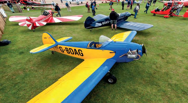
If you decide to build a Taylor Monoplane today, then the hours of work required are no different to if you were building one in the 70s. There are plenty of other single- seat aircraft that needn’t break the bank to build and own, but again, they all take a large investment of time to make the parts to build the aircraft. Happily, I think there’s a solution to this. Today, with the advent of computer-aided design, and technologies such as laser and water-jet cutting, plus 3D printing, we should be able to create an aircraft that could be assembled much quicker and with greater ease.
Above So you want to design your own aircraft… ?
This is the first in a series of articles where I look at the various stages of an aircraft’s conceptual, preliminary and detailed design, for a low-cost aircraft with a ‘modern plans-built’ approach. So, will this aircraft ever fly? While I can’t say for sure, my main hope with this series is to help encourage those who have considered designing an aircraft to do so. Designing an aircraft does take a lot of detailed work but the mathematics involved isn’t too complex. If you have a basic understanding of algebra and are comfortable rearranging basic formulae, you should be OK, and if you don’t, hopefully I’ll still be able to help you gain a better understanding. I also hope this serves as a good education to those who often look at parts of their airframe and wonder how a designer arrived at the size of a longeron or spar cap, for example..
Key objectives
As with any design, the final product must meet a series of criteria. All aircraft as you know are a series of compromises, and determining what these will be early on, will make life a lot easier for us later on in the design. As I mentioned, I am aiming this aircraft to be a truly affordable, quick to build plans-built aircraft. I have come up with the following design objectives.
• An aircraft that is very simple in its construction – wood and composite with metal fittings.
• An aircraft that if equipped basically, can be built for around £6,500 – VW or similar powerplant, minimal instrumentation.
• Stored easily and incur minimal ownership costs
• Capable of cruising at 90mph
• Has a payload of approximately 140kg – this will be a single place machine.
And that’s about it, the longer this list gets, the harder it will be to satisfy the key objectives. If you intend following this series of articles, then keep hold of the copies, we’ll be referencing back to various stages like those objectives above, quite frequently.
To ensure that our design meets some key criteria, you would need to select the most appropriate design code at this stage. If you aren’t familiar, designing an aircraft to a design code such as CS-VLA or BCAR Section S ensures the final design conforms to recognised design criteria which hopefully means that it will be accepted as eligible for the issue of a Permit to Fly. The codes determine things like V speeds, G limits, stall speed curve, appropriate safety factors on fittings and so on, and basically act as a guide to designing a safe aircraft in the particular size category concerned. You can find these online, or search for ‘LAA Technical Leaflet 1.13’ on the LAA website. For the aircraft design being covered in these articles, we will be following CS-VLA. Why? Simply because the envisaged aircraft won’t be a microlight (BCAR Section S) and the requirements in CS-VLA are much simpler than those in the more demanding CS-23 standard.
What will be covered?
The amount of analysis in any design depends entirely on tThe amount of analysis needed for any design depends entirely on the concept and objectives. That said, it will always be necessary to do some basic analysis of the loads and stresses on and within the wings, fuselage, tail, undercarriage and control system etc. If you are designing something that, say, cruises at 180mph carrying two people on a Rotax 912 UL, then your design will also need considerably more in-depth analysis into the aerodynamics and careful selection of the airfoils etc. You’d also need a very efficient structure, optimised to the ‘nth degree to keep the weight down, which would mean extremely detailed structural analysis because there’d be no scope for unnecessarily strong parts – to minimise the empty weight, everything must be strong enough, but not too strong. This is why high speed aircraft designs such as the MCR-01 surely presented a much greater design challenge than, say, an Evans VP-1 Volksplane, where the design goals are likely similar to ours.
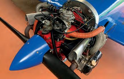
Left A low cost project needs a low cost engine, like a Volkswagen.
Generally speaking, the simpler the aircraft and its structure, the simpler the analysis. A wooden, four longeron type fuselage, for example, is considerably simpler to analyse than a composite monocoque or aluminium structure (aluminium aircraft in my mind being the hardest to design).
Our project is designed to be very simple from the outset and we’re not expecting any jaw dropping performance figures, and so the analysis should not present any particular problems. For our project, we will be looking at the following topics:
Design data
• Finalising our concept, arriving at our 3-view drawing
• Estimation on empty weights and CofG
• Detailed Specification – Wingspan, length, tail areas and arms etc.
• Performance estimation
• Stability estimates
Loads
• Deriving a flight envelope
• Aerodynamic loads on the wings, tail surfaces and control surfaces.
• Fuselage loads due to the engine, pilot and tail loads, engine mounting and fuel tank.
• Undercarriage loads considering different arrangements.
• Control system loads in the control circuit.
Stress
• Wing spar stressing – determining the stress within the spar caps and shear webs as well at the attachment fittings. We will also check the stress at the control surface hinges. Wing torque and drag/anti-drag loads also need careful consideration.
• Fin and tailplane stressing.
• Fuselage stressing – determining the stress in the longerons, fuselage skin, firewall and seat(back).
• Undercarriage stressing – Finding the stress and deflection of the undercarriage.
• Control system stressing – determining the stress within the bell cranks, pushrods, horns, cables and brackets.
Specifications
Wingspan - 6.7m
Length - 4.8m
Height - 1.75m
MTOW - 350kg
Paverplant - 60hp VW
Now I must stress (sorry!) that there are quite a lot more detailed loads and stressing involved when designing an aircraft than the above. Realistically though, if something is attached to an airframe, either the ‘thing’ itself or the means of attachment need to be checked, usually both, and that goes for the entire aircraft. This series of articles is intended to cover the main structural elements and serve as a good guide/education, as opposed to a being a complete step-by-step tutorial. I’ll also point out some of the most helpful texts available where you can find out more!
Step 1: The concept sketch
Defining the basic shape and outline of a design is actually quite a lot more complex than drawing an aircraft with pleasing lines. Think of those simple project objectives –any curves in the design will add to the complexity of construction. There’s lots to keep in mind. Is the wing spar going to slot nicely in the fuselage or could it foul the pilots legs or head? Is the wing in a sensible position or will changes in pilot weight cause drastic changes in CofG? This also applies to the fuel tank and baggage. Does the tail look right? Is there enough room for the engine? I know these all seem obvious, but it’s amazing how far you can get into a design before realising that somehow you’re left with a one-inch gap between the floor and the seat where you have to locate the control system, and that then leads to complex control system fittings which, you guessed it, don’t comply with those simple build objectives.
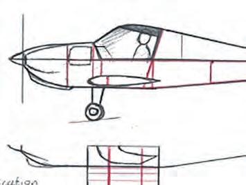
Don’t worry about making beautiful drawings. At this stage you are outlining the aircraft and considering its structure. With a concept sketch, I start by drawing my pilot. I then mark the firewall location, the seat back, instrument panel and wing spar. Then I continue towards the tail. Is the moment arm length between the rough CofG location (25% of airfoil’s chord) and centre of the tailplane and fin sufficient? The rule is, the smaller this arm is, the bigger the tailplane and fin areas need to be. We’ll check these arms and areas later in the process, as well as the wing dihedral, to find out if they are likely to give satisfactory in-flight stability.
Wingspan - 5.5m
Length - 4.6m
MTOW - 340kg
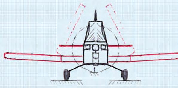
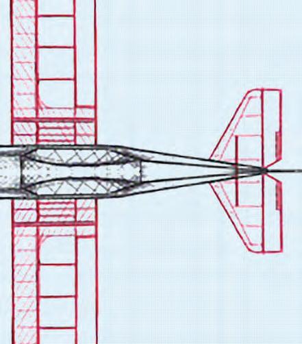
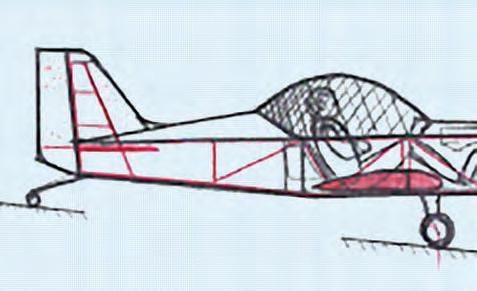
After more than a dozen initial attempts, the low cost LAA type arrived at its first concept as shown in figure 1. It’s always a case of slowly finessing the outline to give both a functional design and nice lines, while staying true to a simple design. Think ahead – for example, will the rear fuselage structure you’ve sketched in work out OK as a support for the tailplane? Where will you mount the tailwheel? Continually question your design, can it be safer, cheaper, easier to make?
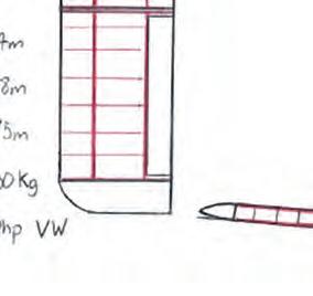
Having given the design some thought, I realised it could be simpler still. And so we arrive at figure 2, which is a little more slab-sided and a touch smaller, but still capable of accommodating my ‘well-fed’ frame. Hopefully too, those lines will be a little easier to build.
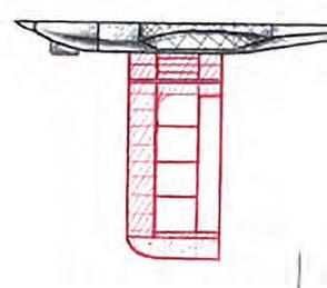
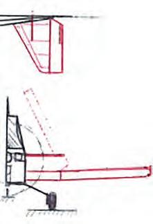
If you’re curious as to the lines marked in red, they mark the location where I am considering the main structural members will be. You will also note that I have opted for a wing folding mechanism that should allow quick and easy folding, in the hope it allows for reduced hangarage costs.
Next step…
In the next step, we will create a proper 3-view drawing from our concept sketch, using that to come up with a detailed specification, which we can use to determine our weight and balance estimates, and our performance estimates. We’ll need to think about how the performance and utility will be affected by tweaking the design for example, what would be the effect of a longer wingspan, wider fuselage, etc etc ?
Squeezing everything into these articles will be quite a challenge so some detailed elements won’t be covered. I will, however, aim to cover the more important elements and where I intentionally miss something, I’ll make it known and give reference material that covers it in detail that would otherwise oversaturate this ‘guide’.
If you are considering your own design, it is well worth while taking a look at LAA Technical Leaflet 1.07 ‘Acceptance procedure for a new design’ as well as the LAA ‘Designing Aircraft’ page on the LAA website, which contains several useful spreadsheets. We’ll be using those in future… ■
The Benefits


