14 minute read
Engineering Matters


Including: Elevator trim tab control failure and inspection and replacement of flexible hoses…
Welcome to ‘Engineering Matters’ – the section of Light Aviation that is dedicated to discussing all manner of topics concerning both technical and operational aspects of the LAA fleet. If you have anything to say that you think would benefit others, then please email words and pictures to LAA Engineering at engineering@laa.uk.com
Elevator trim tab control failure
A Wag-Aero Acro Trainer (similar to a Piper Cub) suffered an in-flight failure of the elevator trim tab control cable. The control is a simple, single-strand wire push-pull type, which fractured about an inch from the tail end. The failure resulted in a fairly violent shaking through the airframe, as the now free-to-move tab caused the elevator to move in sympathy. The pilot carried out a successful precautionary landing. The flapping of the unconstrained trim tab caused the attachment hinge to begin to fail.
Single stand wire controls are commonly found throughout light aircraft, operating everything from trim tabs through engine controls to heater controls. Obviously, they are not as flexible as multi-strand cables and require careful and regular inspection to ensure they remain serviceable. It is worth checking the movement of the control not just at the extremities of the operation but also through its range. It is often at the mid-point where the wire is the most stressed, especially when operating an arm that moves through an arc.
On another aircraft type with a similar elevator tab control system using a Bowden cable to actuate the tab, it was found during an inspection that a spring which should be fitted at the tab end of the Bowden cable, was missing. The spring’s primary function is to ‘load’ the connection between the operating cable and the tab itself, and therefore reduce any free play inducing flutter in the elevator tab at higher air speeds.
A secondary effect of not having the spring installed on this particular set-up, was that the tab could travel downwards (the cable attached to the tab on the lower surface) 25% further than it should. Although it would probably never need to be trimmed that far down (nose-up trim), if it were left in that position, it might cause control column forces far more than the system (and the pilot) was designed for. Additionally, if a flying control is allowed to ‘over travel’, it could get into a geometric lock situation, preventing normal control of the system.
It’s always best to check control connections are as called in the build or maintenance manual, and if not clearly defined in one of those, check the parts catalogue. Parts catalogues should not be considered the primary source of determining whether components are correctly assembled.
EuroFOX nosewheel tyre change revisited
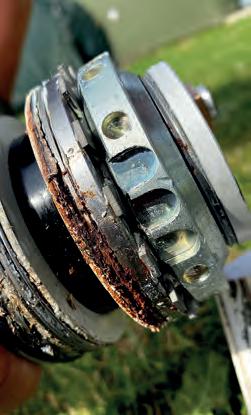
As part of the investigation into the nosewheel installation issue that was mentioned in Engineering Matters, January 2022, the ‘how could this happen’ question was obviously discussed. John Bisset, one of the gliding club members involved in the task has very kindly written some words as to how indeed such an event can happen. But for the grace…
“I am one of the two people principally involved in changing out the nosewheel on the gliding club EuroFOX, which resulted in an overturning accident on 29 May 2021. I felt there were several useful learning points in this which I thought might be worth writing up for others. Embarrassingly, I am a professional engineer, now retired, from a rather different discipline. This note is not written as an excuse or as a ‘mea culpa’, but simply to highlight errors easily made, easily seen in hindsight and all too simple to fall into. Sadly, none are new, I have come across them in other industries.
“The preliminaries to the accident. Our nosewheel was well worn and cracking, and we needed to replace it. This was work we could do within the scope of pilot maintenance. Before removing the nosewheel we investigated various alternative ways to do this. There was little information in the aircraft’s maintenance manual; when we asked the UK agents if any more detail description was available, we were told there was not.
“Our first preference was to remove the entire assembly, wheel and fairing, with the intention of removing the fairing and not refitting it. This was for several reasons. It made checking of tyre pressure difficult and on several occasions the nosewheel pressure was found to be well below specified pressure. The fairing hid most of the wheel, so pilots checking the aircraft were not aware of the low pressure. We operate from a grass strip. In summer either the close-fitting fairing filled up with damp grass clippings until the wheel jammed or it filled with dry grass, which then risked overheating and a possible fire. Being a very tight fit, clearing the grass out was hard to do, so either modifying the fairing or complete removal made sense. When towing, there is little drag benefit in having the fairing fitted.
“Since no detail information was available, and removal of the whole assembly would have involved removing and refitting / resetting the vibration damper, adding some additional complexity, we elected to remove the wheel alone. This was agreed beforehand with our local LAA Inspector.
“The fairing fitting appeared to be secure and well fixed. After wheel removal, the interior of the fairing was cleaned out of residual debris. On looking in, I saw no sign of movement of the fairing relative to the axle forks at that time. All was lined up. When we offered up the wheel for refitting into the fairing and axle fork, it took some wrestling and manoeuvring to get the wheel to go back into the fairing. When we did finally get the wheel into position, I checked that everything was lined up by looking through the axle aperture. Since I could see daylight, with no occlusion, I felt we had got everything lined up. The axle went through easily, everything tightened as it should and the wheel alignment, track and rotation all seemed normal. As a result, I was confident all was well – we all were.
“In hindsight, several thoughts occur. Yes, I assumed; a classic engineering no-no. We all thought we had checked properly. We were working in a hangar, using hangar light plus torches. Access to the nose gear is limited even with the tail tied down. The best torch had failed by the time the final checks were done. Would a stronger light through the axle hole have alerted me to my error? It is hard to see up into the fairing area from below.
“Because of the style of the fairing mounting, following the cleaning out of debris, it seemed to me that the fairing was well fixed with respect to the axle. I (we) overlooked the possibility that significant movement could occur while offering the wheel up into the fairing. Annoying on my part at least, I had seen a similar error years ago in sailplane control rigging. I should have remembered.
“A photograph provided post-accident by the manufacturer and/or UK agent caused a definite ‘ah-ha’ and ‘if only’ moment. The picture said it all. If there had been any comment within the maintenance manual, or even better a picture like that, the error would have been caught. The picture of course showed a fairing and leg inverted on a nice clean work bench with good visibility. Nonetheless, the point would have been made!
“We have subsequently heard that a comment may have been made within the aircraft build manual. This is something we have never seen, so cannot confirm. If true, it highlights another ‘hole in the cheese’. The designers may feel they have properly mentioned this. If the information does not get to the eventual maintainers, only to the builders, there is an obvious gap. I wonder if the slightly unusual part pre-built, part ‘self-assembly’ philosophy of EuroFOX contributes to the gap here.
“It seems to me that a combination of factors, none new, combined to catch us out. Assumption of good fixity – I should have asked myself how I planned to assure myself of that.
“Reassurance by fellow workers. We both felt the positioning was good. Our after-job checks appeared to show what we expected to see. Did we challenge each other, or was the presence of a ‘competent other’ a reassurance?
“Incomplete information from the designer/builder. ‘If only we’d known’. Perhaps the information existed, but if so, it got lost somewhere along the line. I’ve been on both sides of that one! How do you keep information current? How do you ensure everyone understands the design and its limitations, years later?
“We did discuss the job beforehand and specifically looked for possible issues and traps, which is why we didn’t remove the entire assembly. At that time, we were quite concerned that it might not be possible to remove the fairing without damage after many years in place, corroding the threads on the fixings. I suspect that contributed to the impression of an item firmly fixed in place. Perhaps that explains why none of us thought axle misalignment was a major risk…
“As a final thought, when an experienced Cessna maintainer walked into our hangar and saw the damaged aircraft, disappointingly he instantly recognised the cause, before we had said a word. Apparently that same mistake has been made several times with Cessna singles. Lack of crossover of information between disciplines and operators/maintainers? That’s not a new gotcha either.
“So – if in doubt, talk to folk, spread the word, even of your own near misses. Maybe we can reduce the repetition rate that way!”
Propellers
Continuing the propeller theme started in last month’s Engineering Matters with the corroded MT propeller blade ferrule, here are some more ‘issues’ with propellers – one too tight, one too loose and one cracked.
Powermax
Inspector Phil Trangmar was asked to look at a Powermax variable pitch propeller fitted to a TL2000UK Sting Carbon S4 that had ceased to be variable. On discovering that the blade pitch rotation was somehow restricted, there was no backlash in the blade and any rotational force applied to the blade could be seen to be straining the pitch change servo push rod.
With the owner’s agreement, Phil disassembled the hub and found that inside the hub, the blade bearings were devoid of any form of lubrication. The pitch change push rod had in fact bent under the load applied by the servo.
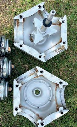
Powermax call for a 500-hour service for this propeller, but there is no requirement for lubricating the propeller between the service intervals, and this propeller was nowhere near 500 hours time in service.
Unfortunately, there was no option but to replace the propeller
Kaspar KA4/3
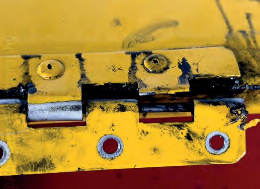
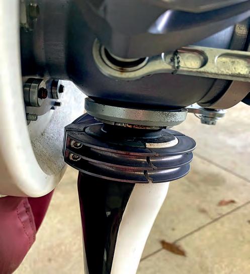
John Tiley, the owner of a Sportcruiser fitted with a Kaspar variable pitch propeller, was carrying out the ‘gurgling’ procedure to check the Rotax engine’s oil level on a pre-flight check when he discovered that one propeller blade had become loose and the blade pitch could be altered easily by twisting the blade by hand. The blades in the KA4 propeller are each independently clamped to the hub mounted mechanism which is driven by a pitch motor to vary the blade pitch.
The cause of the looseness of the blade was that the pitch change clamp that holds the blade had completely cracked through. One would not like to think of the consequences that a failure like this would have caused in flight.
Kaspar has said that it has not heard of this problem before. Previously there was a failure near the clamp attachment bolts that was thought to be caused by over torquing.
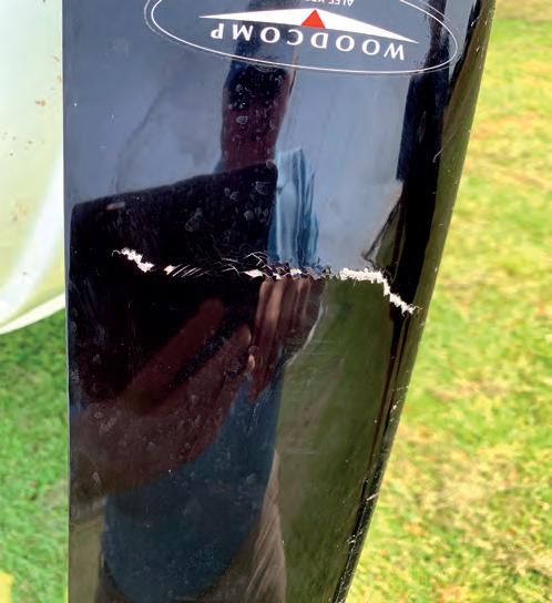
Woodcomp Propuls AE
The owner of a EuroFOX arrived at their destination after an uneventful flight. Prior to the flight the aircraft had undergone a thorough pre-flight inspection conducted by both the owner and his passenger who was also an experienced pilot.
On returning to the aircraft for the flight home, as they approached the aircraft, they could immediately see that there was a problem with one of the propeller blades. On closer inspection, they found that there was a crack across the front face of the number two blade.
There were no signs of any impact damage or other possible cause and as a taildragger, the propeller is well clear of obstructions while taxying.
Rotax oil pressure sender relocation
Sometimes, making a simple modification might be considered to have no major effect on the world as a whole but it’s important to step back and consider the ‘what if…?’ implications.
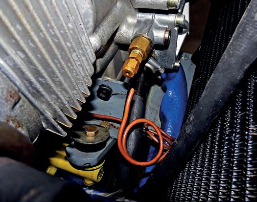
At some stage, the Rotax 912ULS oil pressure sender on a Zenair CH 750 was relocated from the standard position on the front righthand side of the crankcase to the engine frame. Some people have favoured this approach to reduce fluctuations in readings caused by vibration.
PTFE and sealant on fuel fittings
In an article about ‘winter starting’ in the January 2022 issue of Light Aviation, there was a photograph of a carburettor which looked as though it might have well had PTFE tape installed on the fuel inlet fitting. I have no idea what the subject aircraft was in the picture, but as a point of note, PTFE tape must never be used on aircraft fuel fittings (or many other fluid or other systems).
Apart from it not reacting well to fuel and therefore not acting as a sealant for long, PTFE tape and other inappropriate sealants (such as RTV) can easily block fuel lines.
There are some excellent sealants and lubricants to use on aircraft fuel systems such as EZ TURN, which is available from most aviation suppliers. It may not be cheap but you don’t need much (so a tube lasts forever!), and it works, both as a sealant and as a lubricant to prevent galling of the threads.
Right This picture was featured in January’s LA – spot the PTFE tape!

Inspection and maintenance of flexible hoses
It is a fact of life that flexible hoses installed on aircraft suffer through a variety of causes. The toughest environment that they exist in is ‘firewall forward’ where they not only have to put up with whatever medium they are carrying, but also live in a pretty harsh environment with extremes of temperature, especially oil pressure hoses.
Most manufacturers’ maintenance schedules dictate a life or inspection regime for flexible hoses and the CAA Light Aircraft Maintenance Schedule (CAP 411), which formed the backbone of certified general aviation maintenance for decades, also included inspection tasks for flexible hoses.
The industry ‘norm’ (and as is called up in LAMS) is to pressure test fuel and oil hoses when they are six years old – then every three years after that. Hoses do not have an indefinite life and a three-year pressure test should not be assumed to be any kind of guarantee that the hose will be serviceable for yet another three-year period.
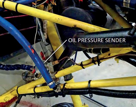
Normally, the sender is screwed directly into the crankcase. On this aircraft, a fitting had been installed in the crankcase and a brass pipe made to join the fitting to the relocated sender.
Unfortunately, the pipe failed at the fitting with the result that the engine oil was lost overboard and the engine seized, resulting in a forced landing. The cause may have been a poorly made pipe flare exacerbated by having one end subjected directly to engine vibration with the sender attached to the more solid engine frame.
A number of manufacturers now supply Teflon hoses, which should have a much longer service life than the traditional rubber hose (including the wire-braced type). While these hoses may not require pressure testing or replacement at the same intervals as the rubber, they can still suffer from outside influences including chafing or contact with the exhaust system. An example is the Rotax 91x series engines where the Teflon fuel hoses do not have to be replaced until the engine is overhauled (or replaced) but they still have to be inspected as part of the scheduled inspection for damage.
Flexible hoses may look fine at an initial ‘in situ’ inspection, especially if protected with ‘firesleeve’, but once the hose has been removed, a more thorough inspection can be carried out. This would include checking for age-hardening, or hidden chafing damage or burn marks where the hose may be touching part of the exhaust system
If the firesleeve can be removed from the hose, then this allows for a more thorough inspection of the outer surface of the hose. It has been known for hoses to develop a pinhole leak, but the firesleeve has absorbed the leaking fluid, masking the failure.
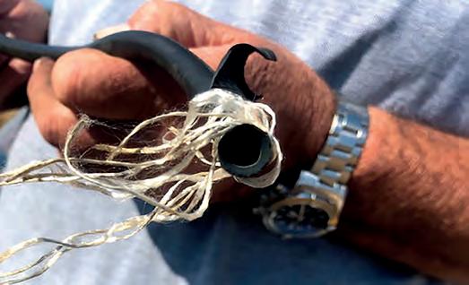
It has been well documented over the years that the ‘modern’ fuels may contain substances that are not exactly rubber friendly. Some hoses are made up of layers and it may be that an outer layer is fine but the condition of the inside layer of the hose has started to degrade.

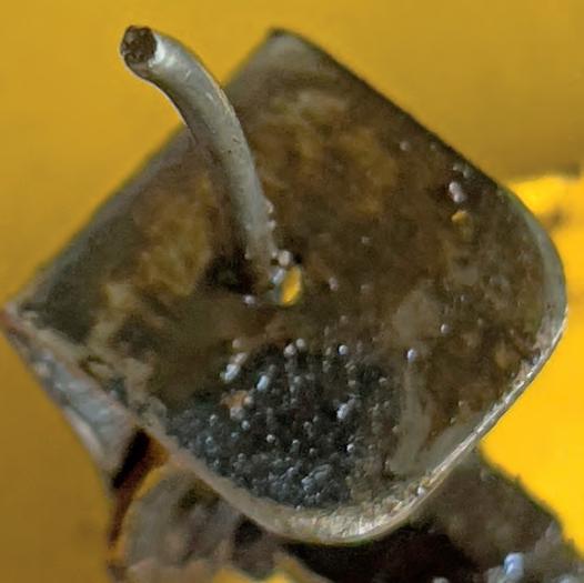
Recently, a Jodel suffered a loss of power on take-off resulting in airframe damage in the subsequent off-airfield landing. It is possible that the inner layer of the carburettor fuel inlet hose had degraded to the point that it caused a severe restriction to the fuel flow.
Hydraulic and air/instrument hoses should not be forgotten when it comes to pressure testing and inspection, although they tend not to suffer quite as much as engine fuel and oil hoses, their condition should still be monitored and replaced when necessary. Leaks in the pitot/static system can cause large errors in instrument readings.
Aircraft specification hoses normally have identity tags on them that include the date of manufacture and it is common practice to etch a pressure test date on the tag.
Further information on the inspection and pressure testing of flexible hoses can be found in Chapter 20: Leaflet 20-50 of CAA CAP 562 ‘Civil Aircraft Airworthiness Information and Procedures’ (CAAIP). CAAIPs makes a very worthwhile read as a reference library for all manner of maintenance tasks and procedures.
LAA Engineering housekeeping
• When emailing LAA Engineering about something that concerns a specific aircraft, please include the registration (or project number if the aircraft has yet to be given a registration) in the email subject heading.
• The Propeller Type List (PTL/1) allows certain propellers to be fitted to specific airframe and engine combinations without going
LAA Engineering charges
LAA Project Registration
Kit Built Aircraft £300
Plans Built Aircraft £50
Initial Permit issue
Up to 450kg £450
451-999kg £550
1,000kg and above £650
Permit Revalidation
(can now be paid online via LAA Shop)
Up to 450kg £170
451-999kg £220
1,000kg and above £260
Factory-built gyroplanes* (all weights) £275
*Gyros note: if the last Renewal wasn’t administered by the LAA, an extra fee of £125 applies
Modification application
Prototype modification minimum £60
Repeat modification minimum £30
Transfer through a formal modification application process.
Above This Jodel fuel hose shows how part of the internal reinforcing material has started to break free.
Please ensure that the aircraft’s Operating Limitations document includes the ‘or as LAA (PFA) PROPELLER TYPE LIST (PTL/1)’ statement under ‘Propeller Type(s). If this is not stated on the Operating Limitations document, please contact LAA Engineering to have the Operating Limitations document amended. ■
LAA Fleet Summary
(from C of A to Permit or CAA Permit to LAA Permit)
Up to 450kg £150
451 to 999kg £250
1,000kg and above £350
Four-seat aircraft
Manufacturer’s/agent’s type acceptance fee £2,000
Project registration royalty £50
Category change
Group A to microlight £150
Microlight to Group A £150
Change of G-Registration fee
Issue of Permit documents following G-Reg change £55
Replacement Documents
Lost, stolen etc (fee is per document)£20
PLEASE NOTE: When you’re submitting documents using an A4-sized envelope, a First Class stamp is insufficient postage.
Recent Alerts & AILs
(check the LAA website for further details)
Europa Aircraft – All Variants: Door Losses
LAA Alert: LAA/AWA/21/08 Door Losses
LAA AIL: MOD/247/012 Door Latch System Stop
EuroFOX Tricycle Undercarriage (3K version):
Fuselage Structure
LAA Alert: LAA/AWA/21/09 Fuselage Structure
Under Seat Pan Weld Inspection
LAA AIL: MOD/376/005
Visual Check of Weld Cluster Under Seat Pan
Zivko Aeronautics Inc. Edge 360, Edge 540 and Laser Z200: CAA MPD 2022-001
Aileron Centre Hinge Attachment
MT-03, MTOsport, MTOsport 2017, Calidus and Cavalon gyroplanes: CAA MPD 2002-002 Rotor Blade Inspection/Replacement/Life-Limitation