9 minute read
3.1 GEAR SYSTEM & BALL BEARINGS


3.1.1 GEAR SYSTEM
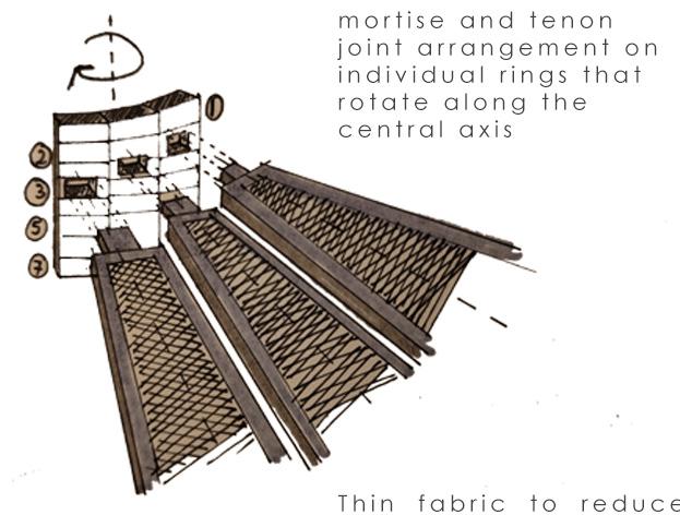
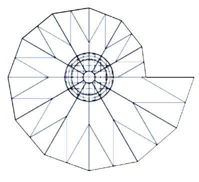
The main design characteristic of this Urban Shading is the central pole to which the 12 fins are attached. In the initial concept, 12 rings are stacked on top of each other around the central pole. Then, the 12 fins are attached to these rings which rotate around the central axis separately (see figure x). In order for this concept to work a gear system had to be designed for this specific type of rotation.
Advertisement
When brainstorming about this rotating mechanism, a main design issue came up: how can every fin move individually with such a small amount of space available in the pole? In addition having enough strength to keep the pole from buckling, bending, or breaking. The idea came up to move only the lowest fin and “pull” the rest of the fins with this lowest fin. This also made it easier to handle manually from the lower part of the pole. When this idea was made final some steps were taken in the design process to get to the final design;
1. The fins are rotated by only rotating the lowest fin, soon the design consisted of a handle on hand level that drives a worm gear inside of the pole this worm gear makes it so that the handle rotates the fins and not the other way around. This worm gear drives in its turn a spur gear which rotates a pole that moves this force up to the plane of the first fin, where another spur gear is located. This spur gear gives the right rotation and plane for the first fin to be rotated. (see figure x).
This step was made very fast in the process and the team believed this would work and give the desired rotation to the top part of the pole. Then the question came up of how can this system rotate the fins from the central axis while also having the structure, the pole, in this same axis. After a lot of sketches, research, and talks with Marcel and Nadia, the team came up with the idea of an internal gear, so that the central axis allows space for the structure.
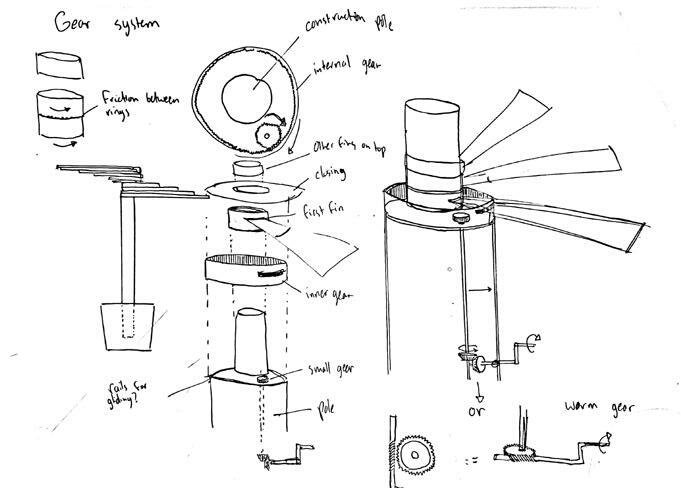
2. The spur gear drives an internal gear which is connected to the lowest joint; the lowest fin starts rotating.
The first fin rotates, and now the team had to figure out how the next sequence of fins is going to rotate from this first one. A lot of options were discussed: for example hooks on the fins to catch the hook on the next fin to make it rotate or rails on the fin structure where a wheel rotates in until a certain point where it is stopped and the next fin starts rotating. The “stoppers”, as called in this project, on the fin itself were quite a challenge because they added undesired weight to the fins. At a certain point, Nadia came up with the idea to put the stoppers inside the joint and make it part of the mold design. This idea was worked out further
3. When the first fin has rotated 30 degrees, a stopper inside the joints’ H-section ‘‘catches’’ the next joint, and that fin also starts rotating, then a stopper on the next joint catches the joint on top of that, and so on; all the fins rotate after one another.
To ensure the joints around the pole are able to rotate without having a lot of resistance, the team had to figure out how to connect the joint to the pole to have enough stiffness while also rotation is not hindered. After some talks and discussions with Marcel, the objects we needed were quite clear: ball bearings.
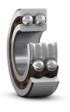
Not knowing how ball bearings worked the team had to do some research into the different kinds of ball bearings available. Explanations of Marcel made this part easier and the team concluded this project needed two different kinds of ball bearings: a thrust ball bearing and a deep groove ball bearing.
Thrust ball bearing:
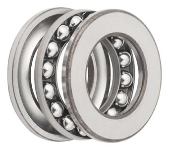
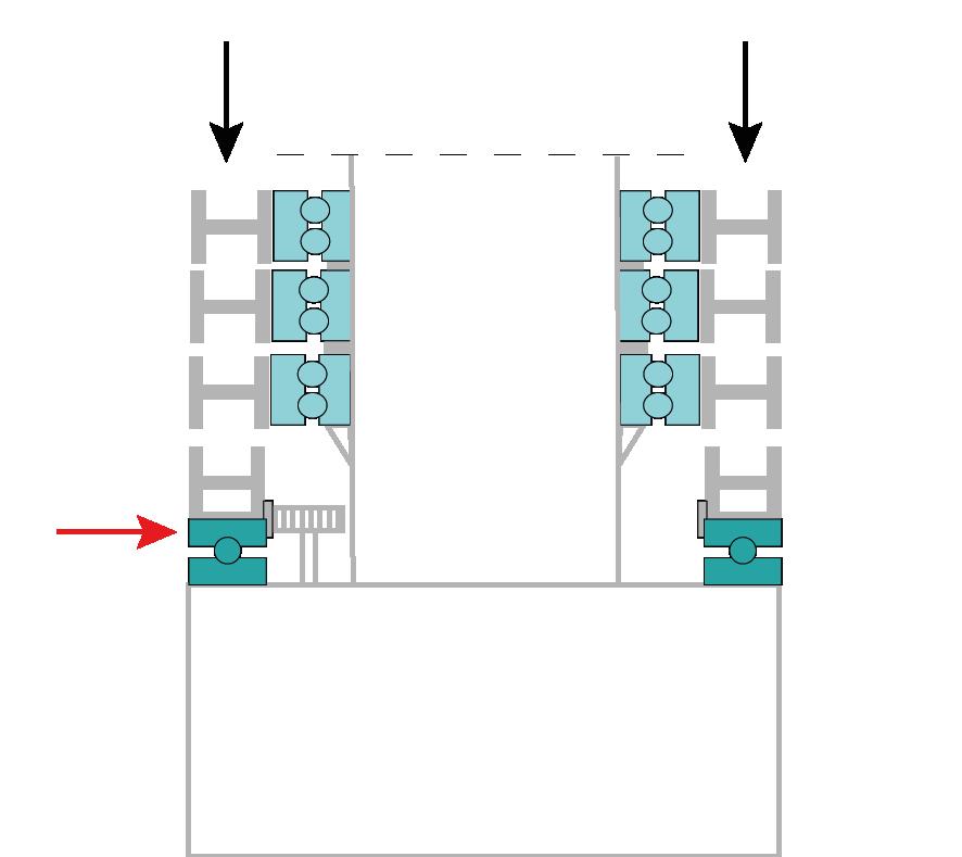
Thrust bearings accommodate loads that act predominantly along the axis of the shaft; axial loads. It consists of two shaft washers which are separated by balls; this makes it so that the two washers can rotate relative to each other without resistance. In this project the internal gear and the lowest joint are attached on top of the top washer, see figure x.1. The lowest washer is attached to the pole. The spur gear can then rotate the internal gear which makes the top washer (including the joint) rotate.
Deep groove ball bearing:
Deep groove ball bearings are robust in operation, requiring little maintenance, can operate at high speeds and accommodate radial and axial loads in both directions. In this project these ball bearings need to accommodate axial loads, see figure x.2. The ball bearings are jammed inside the casted joints, attaching the outside washer of the ball bearing to the joints by resistance. Then the ball bearing and joint are stacked around the central pole and put on the bearing flanch. Now the outside washer rotates relative to the inside one making the joint rotate without resistance.

3.2 PLACEMENT ON BOLLARDS
To determine the optimal configuration of the OSTRA sun-shade, a shadow evaluation was conducted utilizing a 3D Sun path website. Six different iterations were examined.
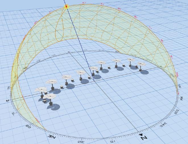
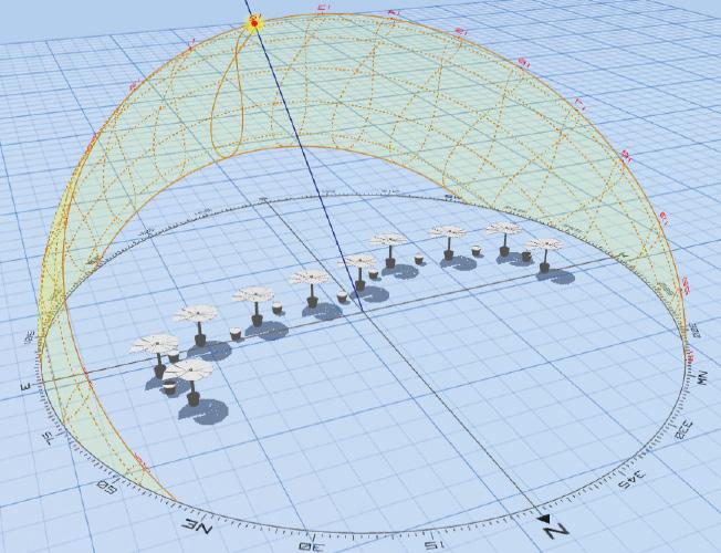
The primary criteria used to evaluate and select the most suitable configuration amongst these six iterations include; a. The aesthetic impact on the overall site and the presence of an over-crowded appearance b. The potential for one shade to obstruct the adjacent one c. The distance between sun shades. d. The necessity of tilting the sun shades e. The orientation of the longer fin in relation to the site’s sun path
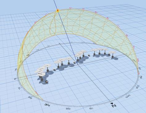
Configuration 1: Every bollard is occuped.
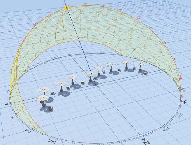
Configuration 2: One of the two bollard
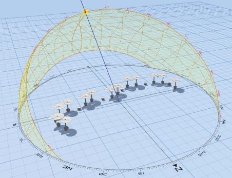
Configuration 3: Two of the three bollards
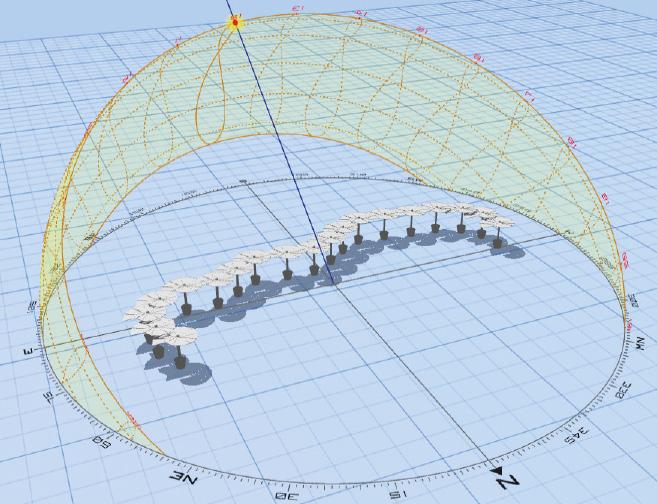
Configuration 4: Three of the four bollards
Configuration 5: One of the two bollards but the inclination is different than 2 and 6.
Configuration 6: One of the two bollards but the inclination is different than 2 and 5.
Decision: After conducting the shadow analysis, Configuration 2 was determined to be the most efficient design iteration. This configuration demonstrated a higher level of efficiency by creating a convenient amount of shade without obstructing the adjacent sunshade, and also maintaining an appropriate design aesthetic. After, further analysis and calculations (presented in Section XX), it was determined that tilting the sun shade was not necessary.
Tilting the Sun-Shades
The initial design was including a feature where individual units can be tilted to enlarge the shadowed area underneath the design.
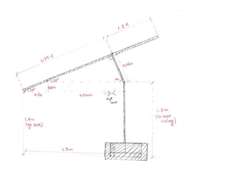
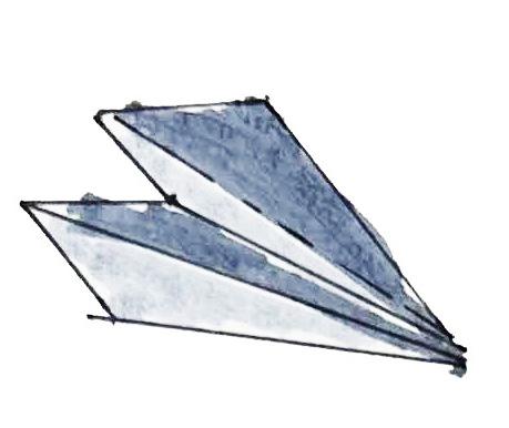
To evaluate if that’s a great idea, further calculations are made considering the sun angle in the specific location, with different tilt levels. Mainly, hand calculations are done which can be seen on the right-hand side of the page and their illustrations are below.

However, upon further examination and analysis, it was determined that the implementation of tilting will not create an efficient amount of shade. This conclusion was reached since achieving a sufficient level of shading through tilting would require an angle greater than 30 degrees, since the sun angle in the Netherlands does not exceed 80 degrees.
Furthermore, the implementation of tilting had the possibility of introducing additional difficulties. For example, the design had to be higher for the lowest edge of the fin not to go below the eye-level to not create a safety risk. Additionally, a more complicated mechanism would be required to operate the design.
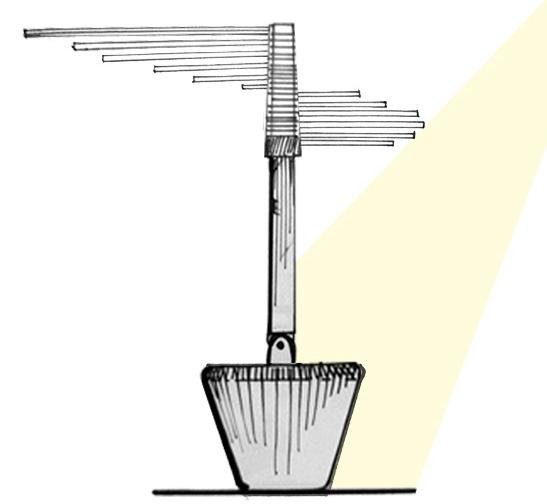
Small to large:
The initial design had the lowest fin at the bottom and the largest on top. As the idea was to rotate just the lowest fin to create the helical movement, the team realized something. A small object doesn’t have the necessary strength to move objects bigger than its size, To do that, more rotation in the driving gear should be incorporated to produce more torque. But that will increase the strain on the user and make it less efficient. A smaller fin the bottom also means that the larger shadow will casted away from the bollard and not closer to the bollard. Thus the sequence of fins needed revision for a better design scheme.
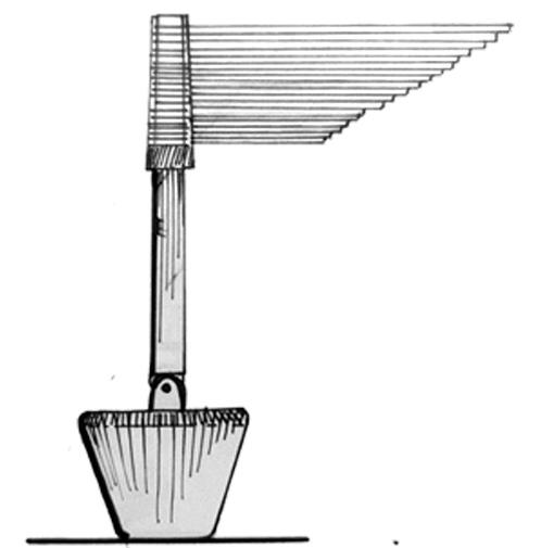
To Small

Once the largest fin was placed in the bottom, no complex gear system was required to produce extra torque for rotation. A larger shadow will be cast close to the bollard thus making it more usable. The previous sequence of fins also proved to be unstable during nighttime when the whole assembly is aligned. After reversing the order, the weight distribution will also prevent it from toppling over when all the fins are brought together, one on top of the other.
Evolution of the design

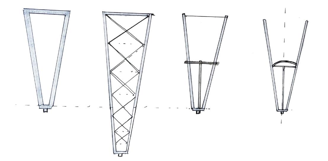
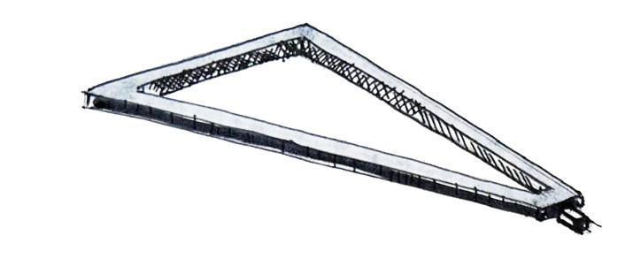
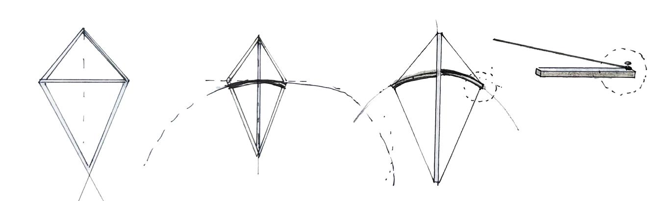
The initial design consisted of a triangular frame structure for individual fins. The team soon realized that this design needs to be optimized to compensate for the extra weight. A few iterations were thought of using a cross-bracing system, tie beams, and even cables but all seemed to have close to negligible effect on the weight distribution. Thus research on new shapes had to be done that are lightweight and can help the design to be more economical.
1:20 scale model
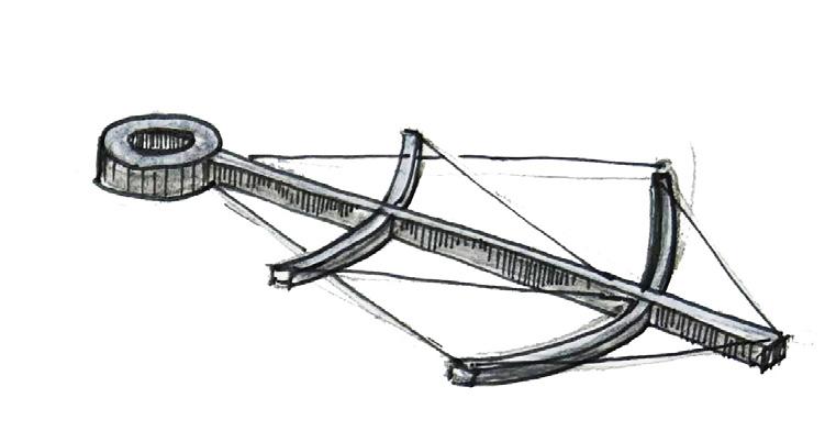
Once established that the initial design needs modification in terms of weight distribution, the team did a study of lightweight structures. First, a windsurf was studied because of its lightweight carbon fiber structure and its construction detail of supporting the fabric. A few ideas were sketched out that made the team aware of the complexities that come with the wind-surfs. The team wanted something more simple in terms of construction and light weight.

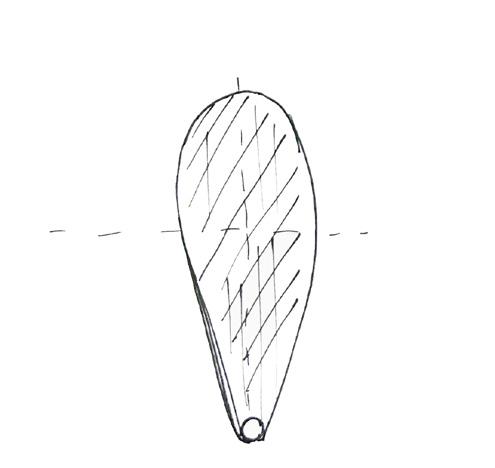

Evolution of the design


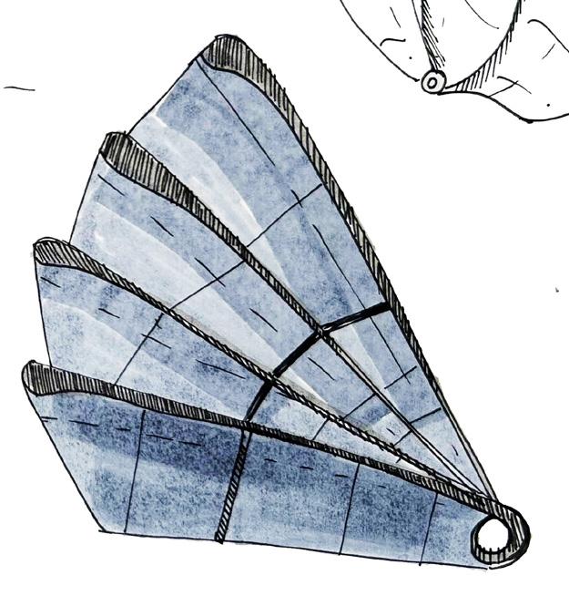
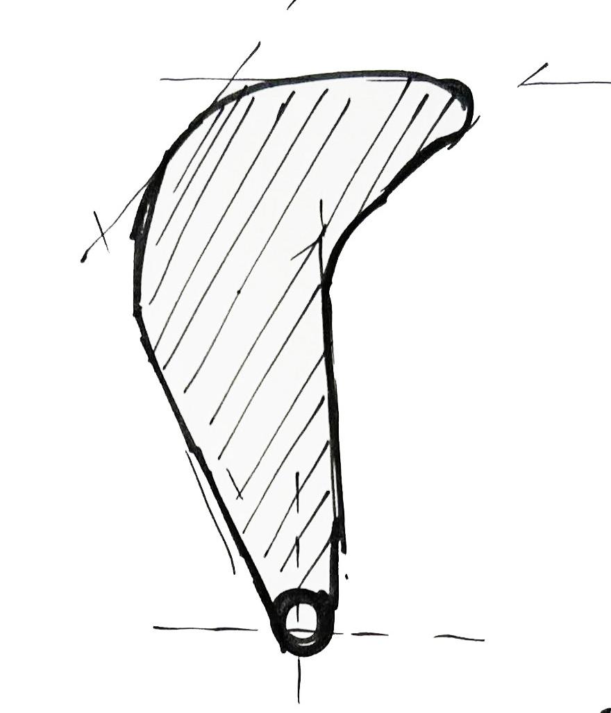
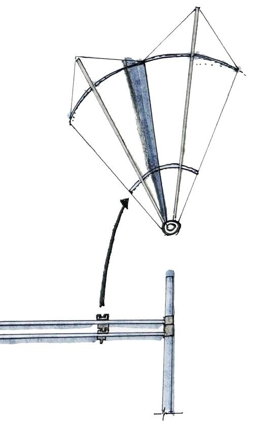
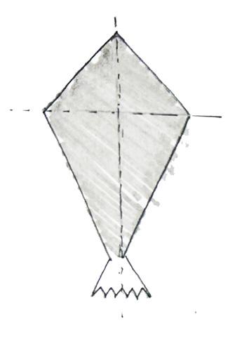
Kites are lightweight structures that inspired the group to finally modify the fin design. The fin will now consist of a central spine that will be connected to the secondary spine structures. The frame will support the fabric on top with the help of cables that will be tied to the spine. the initial design also had provision for external rails that will direct the rotation movement. Rail in the bottom fin will catch the stopper on the top fin to move the assembly in a sequence.
3.6 DESIGN DEVELOPMENT THROUGH MODELS
After sketching, discussing, and thinking everything was on the correct path, came the moment to model the ideas. The working models are not pretty and have fine finish, they do not need to be. Their principal objective is to show errors and quickly test all the possible solutions.
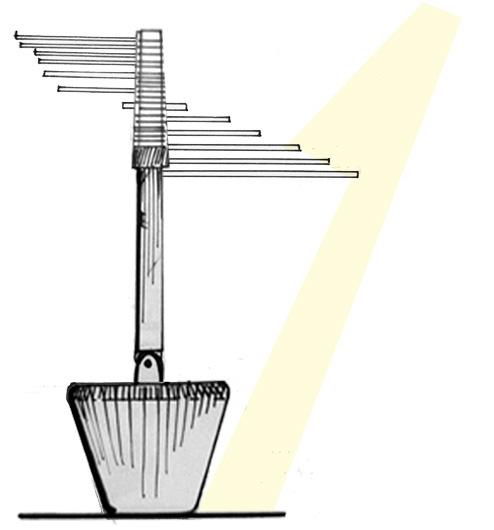
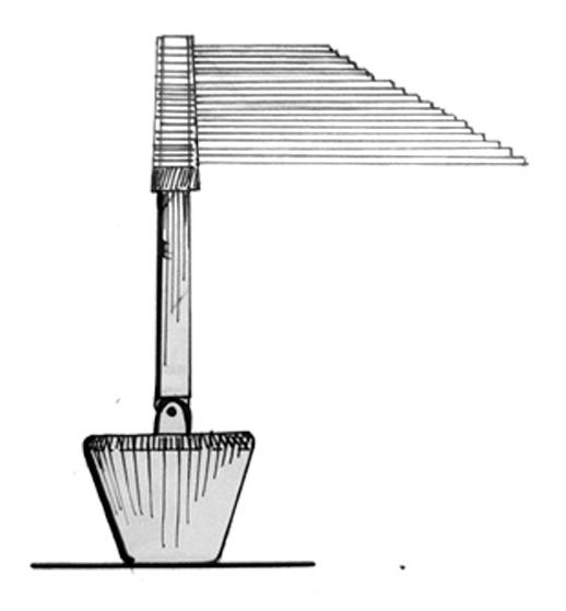
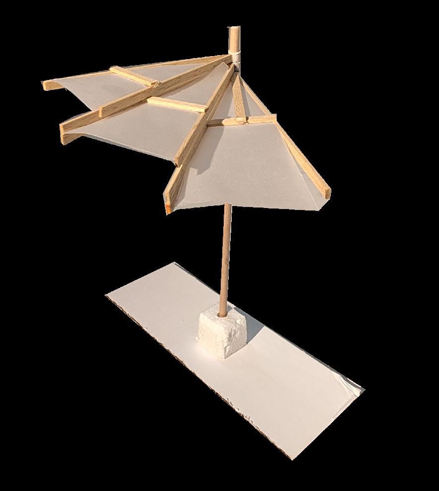
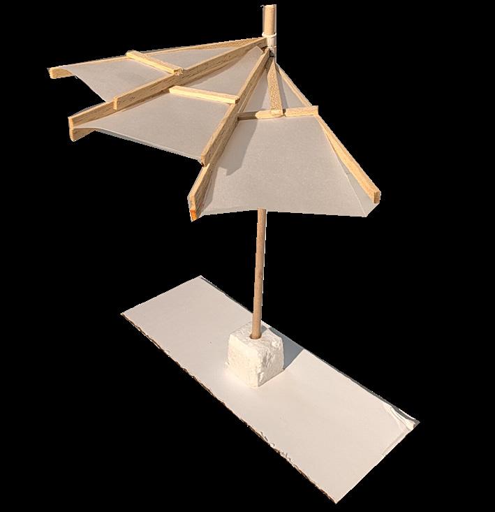
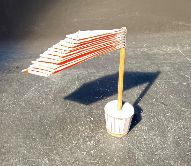
The first model used wood materials for the structures and butter paper as fabric. Issues such as how the hitch between the fins would work or the weight of the structure, which eventually would make the model collapse due to the imbalance, began to arise.
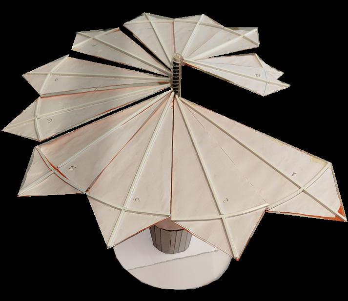
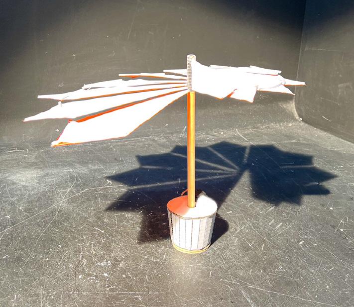
The second model used different materials for the most important components. The bollard was done with a weight inside its cover to represent the resistance to movement due to the fins. The pole used a thicker rounded wooden stick. The joint between the fin and the pole was made with plastic to represent its lightness. For the fin, the improved design, shown in the previous section, was modeled and the structure was made with light plastic. The fabric was represented by a thicker paper and in an attempt to explore colors, an orange paper was selected, but it was glued backward.. at the end the bright color seemed a good option. Not bad after all.
Also, this model was used for a fast shadow study, some criteria were reafirmed and others were revised.
After the study on 1/25 scale was complete, a deeper study of the mechanism was needed. The joint was one of the most difficult parts to solve, as this element contains the ball bearings, and the stopper and is the connection between the fins and the pole. Is the part which binds everything.
The first model was made on a 1/2 scale, using MDF as material, and also, the principal structure from the fin was included. Here, the shape was already set, but other design decisions as where to locate the stopper or how would the fins’ principal structure would fix to the joint were not solved yet. This model gave us the opportunity to detect these issues and solve them.

The second model was made on a 1/10 scale, and as we already knew what it was looking like, it was done smaller. This one shows solutions to problems detected on the first try. The stopper was located in the inner channel with a 30° motion range and an extra plate was included to have the necessary space to screw the fins’ principal structure to the joint.
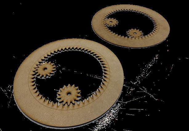
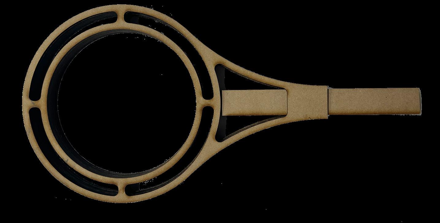
In addition, the gears were modeled to test the mechanical system. The ring represents the first joint, with a ball bearing, which will be the one that moves the rest. These pieces were done by using MDF and laser cut to have a precise cut for the gears teeth
As can be seen in the pictures, laser cutting and handmade techniques for the fabrication of the models were used. Each one of them with a different purpose and depending the quantity of time available.