13 minute read
Tutorial FreeCAD


TUTORIAL
FreeCAD: let’s get curvy!
Add bendy transitions to your parts for a more elegant look
Jo Hinchliffe
@concreted0g
Jo Hinchliffe is a constant tinkerer and is passionate about all things DIY. He loves designing and scratch-building both model and high-power rockets, and releases the designs and components as open-source. He also has a shed full of lathes and milling machines and CNC kit! F irst up is the Additive Loft function, which is a method that creates straight or curved transitions between sketches – it’s a great way of creating complex flowing shapes. To start with, we will make a nonsense object just to see how it works, and then we will create a small ornamental bowl that can be 3D-printed.
On the part design workbench, create a new body and then create a new sketch on the XY plane – this should move you onto the sketcher workbench. Select the rectangle tool and draw a rectangle in this sketch.
As this is a test, we don’t need to add constraints, so close this sketch now. In the part design workbench again, within the same body, create a second sketch.
Click the 'New sketch' button, and select the XY plane for our second sketch.
In this second sketch, use the regular polygon tool to draw a hexagon that is smaller than the rectangle you drew – draw it inside the rectangle, and don’t worry if it overlaps a little.

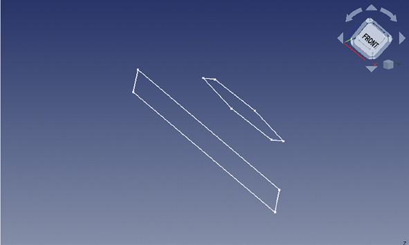
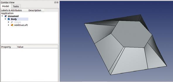
Figure 1 Two sketches in the XY plane with one sketch raised above the other on the Z-axis Figure 2 Using the lofting tool can create pleasing curved results
Again, we don’t need to constrain the hexagon, so close the sketch. The next step is to move the hexagon sketch away from the rectangle sketch in the Z-axis. As both of the sketches are part of the same body, we can’t move the basic position of the hexagon sketch, but we can move the relative attachment point of the sketch. With the sketch containing the hexagon selected, you should see the dialogue box for the sketch in the combo view panel. In this dialogue box, there are three sections of values separated under the headings 'Attachment', 'Base', and 'Sketch'. Making sure you are in the Attachment section, click the Attachment menu, and then click to expand the Position menu. In this drop-down menu, adjust the Z-axis to raise the hexagon sketch over the rectangle – this can be any amount, but we went for 20mm. If you are in an isometric view in the part design workbench, you should see the hexagon sketch rise above the rectangle sketch (Figure 1).
Next, select the original rectangle sketch in the file tree view, and then click the yellow and red 'loft a
FORGE
selected profile through other profile sections' tool. In the combo view panel, you should now see a window – click the 'Add section' button. Having clicked that, select the hexagon sketch in the preview window. As you do this, you should see a preview of the lofted part connected between the rectangle and the hexagon. There are a couple of checkboxes you can click: one is called 'closed' which will close the ends of the lofted object, and the other is 'ruled surface'. Clicking 'ruled surface' toggles the lofted object between having either straight line/plane geometries or curved. It is not that obvious a difference with our simple example, but we will use this in our next lofting project.
To finish, click the 'closed' checkbox and then OK to perform the loft. In the preview window, you will now see the resulting object. Lofted objects are like any other in that you can use other tools on the objects created with them, such as selecting edges for fillets. However, when the surfaces generated become complex and curved, you might find that some tools don't work and we need a different approach.
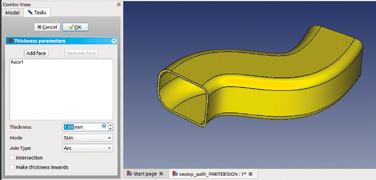
One thing people often try with the lofting tool is to apply a thickness to the resulting object to hollow it out. Sadly the thickness tools only work on simple geometries, so it’s not possible to work this way. However, let’s make a more interesting lofted object – the bowl pictured in Figure 2 – and show how we can create curved objects with defined thickness walls.
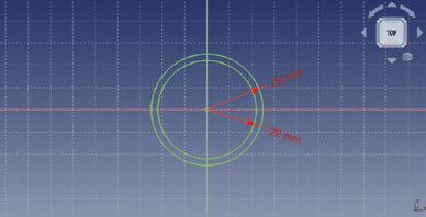
In a new project, create a body and create a sketch in the XY plane. Draw two circles constrained around the origin point and make one slightly smaller than the other; the distance between them will create the wall thickness of our object. We made our sketch with the outer circle having a diameter of 25mm and the inner circle having a diameter of 22mm, to give a wall thickness of 1.5mm (Figure 4).
Close the sketch and then create another sketch in the XY plane. Create a larger pair of circles, but with the same wall thickness – we went for 45mm and 42mm. Close this sketch and then create a third sketch with a pair of circles constrained to match the first set we drew.
With the second sketch highlighted, move these circles up the Z-axis using the same method we used earlier with our hexagon. Move it up by 25mm. Next, do the same with the third sketch, moving it up the Z-axis 60mm (Figure 5). Create the loft in a similar way to the earlier example, starting by selecting the first sketch and then adding the second sketch and the third sketch in that order. If you uncheck the ruled option and the closed option, you should end up with a nice curvy shape, as shown in Figure 2.
Adding one final sketch of a circle matching the outer diameter of the lowest sketch in our bowl means that we can pad/extrude to add a base to our ornamental bowl.
Sweeping along a path is a similar idea to revolving a sketch and also shares some attributes of lofting. However, sweeping uses a user-drawn path or geometry that the extrusion is swept along, rather than an automatically generated one. There are a couple of approaches to sweeping in FreeCAD: one using the part workbench, the other using the part design workbench. Let's look at both to have both methods in our skill set.
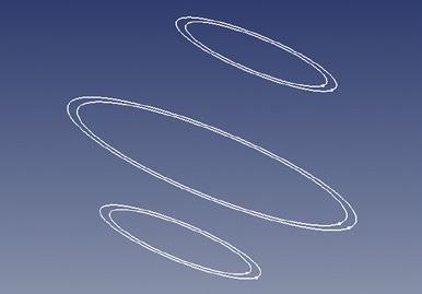
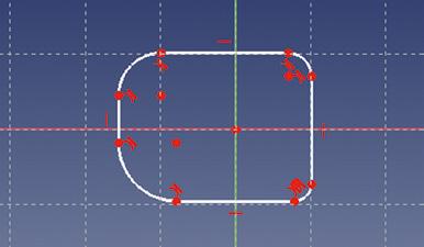
Figure 3 Our completed loft experiment
Figure 4 In this approach, the two circles in each sketch represent the wall thickness of our bowl design
Figure 5 The three sketches for our lofted bowl laid positioned on the Z-axis
Figure 6 The first sketch which forms the profile for our curvy extrusion using the sweep function
QUICK TIP
We covered the basics of the part design workbench in issues 37 and 38.
YOU’LL NEED
A laptop or desktop computer
TUTORIAL
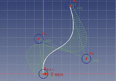
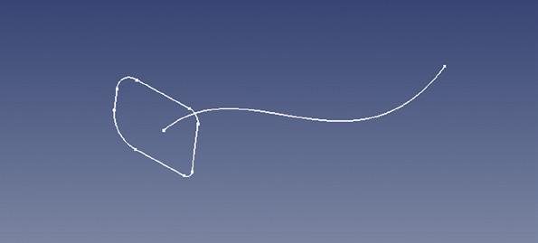
Figure 7 A sketch in the XZ plane using the 'create a Bspline' tool
Figure 8 The profile sketch, and the path to sweep the profile along
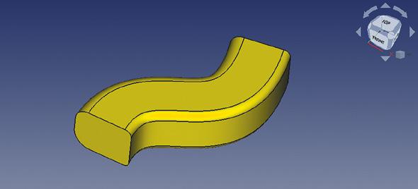
Figure 9 The completed object with the profile sketch swept along the target path sketch
Starting on the part design workbench, create a new project, create a body, and create a sketch in the XY plane. In the blank sketch, make a small closed shape around the origin point. We drew a square and then added some fillets in the corners by clicking the 'create a fillet between two lines or at a coincident point' tool. With the fillet tool selected, click on some corners of the square to add some fillets, and resize them to make an interesting shape. This shape will be the profile of our item we extrude by sweeping it along a path (Figure 6 overleaf). Again, constraining the sketch is unimportant for a simple exploration of the tool.
Close the sketch and then create a new empty sketch in the body. Create this new sketch in the XZ plane. In this sketch, we are going to create the path along which our first sketch profile will be swept. Let's use 'create a B-spline in the sketch' tool. This tool allows us to create a combination of curves in a single line. With the B-spline tool selected, left-click over the origin point in the sketch and pull a line up and to the right or left of vertical, then left-click again and continue with the next line upwards and back towards the centre line. Left-click again and move back out to the right and upwards to create a skewed kind of Z-shape. Left-click to set the next point, and then right-click to finish the B-spline. The two lines you drew should now become curved, and you should see some blue circles. Simply, for now, moving the circles allows you to adjust the curve of the lines. Make a nice swooping curve, such as the one we created (Figure 7).
Close the sketch, and in the preview window, you can rotate your view a little and see that the curved edge we created starts at the origin point, which is in the middle of our profile sketch (Figure 8). To sweep the profile along the curved path, highlight the first sketch we made and then click the yellow and red 'sweep a selected sketch along a path' tool. You should see a dialogue box appear in the combo view panel. In the dialogue box, we need to select the path or object along which to sweep. We can do this in a couple of ways. We can either click the 'Object' button under the 'path to sweep along', or we can click the 'Add Edges' button. Having clicked either of these buttons, we can then select the curved path in the preview window. You should now see a brown preview of the profile swept along our path. Click 'OK' to finish the sweep. You should now have a nice swept object in the preview window (Figure 9).
There are many other options in the sweep utility in the part design workbench that can change the way that corners are handled in a swept object, and also how it handles transforming from one profile to another profile over the course of a sweep, which we will
MAKING PIPES
The part design workbench sweep tool creates single solid body objects, but we can apply some techniques we learnt in the last part of this series where we used the 'Create a thickness tool'. As a quick recap, select the face of one end of our swept solid object and click the thickness tool. In the dialogue box, you can set the thickness of the wall structure, and to make it a pipe object open at both ends, click 'Add face' and then additionally select the opposite end of the swept object.
FORGE
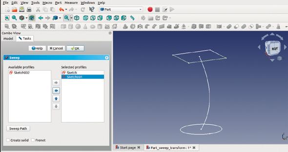
Figure 10 Three sketches ready for sweeping on the part workbench
Figure 11 Adding the profile sketches in the sweep utility
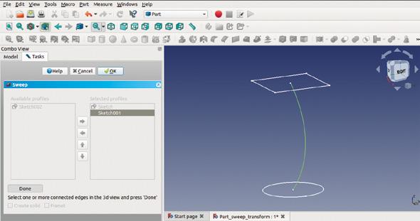
Figure 12 Adding the path that the sweep utility will follow
explore on the part workbench shortly. The other thing of note on the part design workbench is that there is a blue and red icon that is the same as the sweep tool we used, except that it's for subtractive sweeps. This means you could draw a solid object and then cut out and remove a swept path through it.
Finally, let’s look at the sweep utilities on the part workbench, which are laid out a little differently. We will also create two profiles and a path, and the profile will be transformed from one shape to the other along the path. Let's create a new project and go directly to the Sketcher workbench. Create a new sketch in the XY plane and then draw a circle anchored around the origin point – it is up to you if you want to constrain it or not for this example. Close that sketch and then create a second sketch, again in the XY plane. In this sketch, let's draw a square – which should be a similar size to the circle we drew in the first sketch – around the origin point. Close this sketch, but highlight it in the combo view panel so that the dialogue box options for the sketch appear below it. We are going to move the position of the sketch so that it shifts vertically 70mm up the Z-axis. In the sketch dialogue box under the 'Base' heading, open the drop-down menu labelled 'Placement' then, in turn, open the drop-down menu labelled 'Position'. In this menu, change the Z-axis value to 70mm.
You should be able to see in the preview window that the square is now above the circle. Next, making sure nothing is selected in the file tree, add a third sketch with this sketch drawn on the XZ plane. Using the 'create an edge linked to an external geometry' tool, click the horizontal line that is on the upper square sketch. Next, use the B-spline tool to create a nice curved line which starts at the origin point and curves up to reach the centre of the upper square sketch. Then close the sketch, and you should have three sketches roughly similar to Figure 10.
Moving to the part workbench, click the 'utility to sweep' tool. In the dialogue box, you should see the list of sketches on the left-hand side. In turn, select the first sketch containing the circle, and click the right-facing arrow that becomes highlighted to move the sketch into the 'selected profiles' column. Repeat this for the second sketch – the sketch that contains the square (Figure 11). Next, click the 'Sweep path' button, and the dialogue box will become greyed out. Click the path you want to sweep along in the preview window to turn it green, and then click the curved path we created earlier (Figure 12). Next, click 'Done' and then click the 'OK' button. You should now see the circle profile has been swept towards the square on our curved path, and it has transformed throughout the curve to conform to the square profile. In the file tree, this is now a 'sweep' object, and double-clicking the sweep object doesn’t allow you to edit the sweep, but rather, opens the dialogue box to move and rotate the part. If you want to change any sweep parameters, you must select the sweep object and delete it, which will return you to just having the three separate sketches, and then repeat the sweep utility process. In the dialogue box for the sweep utility, you can select to make the object a solid; then, you could create a simple copy and then use the thickness and other tools and utilities.
QUICK TIP
When you are drawing the third sketch, the circles will appear exactly on top of the first sketch. To make it easier, make the original sketch invisible by highlighting it in the file tree, toggling visibility by pressing the SPACE bar.


