45 minute read
Emirates Steel wins Safety Culture and Leadership Award 2020


Emirates Steel, a leading integrated steel plant in the United Arab Emirates, has won the Safety Culture and Leadership Award 2020 by the World Steel Association (Worldsteelorg) in recognition of its AMAN Safety Culture Transformation project.
Advertisement
Acknowledging industry excellence in safety and health since 2008, the award aims to highlight steel companies with superiority in occupational safety management, occupational health management, as well as process safety management. Emirates Steel was recognised for its AMAN Safety Culture Transformation project. In a bid to boost safety standards and reduce Loss Time Injury (LTI) across the organisation, the two-year transformative project which was conducted between January 2018 to January 2020 enabled Emirates Steel to adopt a riskbased approach and to introduce several critical safety management processes – achieving an interdependent level of safety culture development. Emirates Steel’s AMAN project provided training to Emirates Steel’s employees on hazard identification and risk assessment. In addition, as part of the initiative, 80% of Emirates Steel employees and contractors were trained on enhanced Permit-to-Work procedures, and more than 700 coaching sessions were delivered for supervisors and shop floor personnel. The project also led to a 56% reduction in the LTI rate over a two-year period from 2018 to 2020, and to a 26% decrease in the total number of injuries during the same period.
Saeed Ghumran Al Remeithi, CEO of Emirates Steel
Speaking on the occasion, Engineer Saeed Ghumran Al Remeithi, CEO of Emirates Steel, said: “We, at Emirates Steel, are honoured to win this outstanding award given by the world’s leading global steel association, adding a new and significant milestone in our journey towards excellence in all fields. Winning this award, despite the fierce competition with the biggest global steel manufacturers, proves the effectiveness of our safety culture transformation programme. This also highlights our unwavering commitment to leading safety protocols and forward-thinking capabilities throughout the organisation.” AMAN introduced a set of effective safety measures including a new HSE governance and performance programme with a standard dashboard that captures KPIs, facilitating effective performance discussions and driving the required actions and outcomes. HSE Principles and Life Saving Rules including rewards and recognitions for significant contributions to the company’s safety efforts were also launched. This initiative encouraged employees to make an extra effort and contribute to the overall improvement process. Integrating safety into the daily operational processes; and introducing updated procedures on risk assessment, inspections and observations, health and safety reviews, permit-to-work, and incident investigation processes were also adopted as part of the programme. Moreover, through the AMAN project, Emirates Steel launched the MySHEQ digital platform to boost safety performance and manage HSE critical processes. Established in 1998, Emirates Steel makes wire rod, rebar, heavy sections and sheet piles. Per year, it produces 3.33 million tonnes of crude steel. It is is part of ADQ, one of the region’s largest holding companies.
www.kuettner.com


2020


Strategic automation interventions at 4-strand Wire Rod Mill at Bhilai Steel Plant (SAIL)
Automation systems have been designed and implemented in stages at the 4-strand Wire Rod Mill at Steel Authority of India Limited’s Bhilai Steel Plant to improve the overall performance of the mill. Developed and implemented inhouse by SAIL R&D Centre for Iron and Steel and Bhilai Steel Plant, the innovations incorporate advanced controls in strategically selected operations for maximum benefits at an optimised capital investment and minimal mill shutdown.
AUTHORS: Archana Sharan, Ashit Prasad, Anup Prasad, Subrat Kumar Saha, Shyamalesh Saha, Sanjoy Parida, R&D Centre for Iron & Steel, SAIL, Ranchi; Anupama Kumari, Xavier Beck, Deepak Jain, R K Rajdhar, M Hussain, Bhilai Steel Plant, SAIL, Bhilai
CONTACT: Archana Sharan, archana1433@sail.in
Successfully implementing such systems in an operational mill is not straightforward and requires an innovative, multi-pronged approach with a tailor-made control, display and reporting system. The improvised cost-effective measurement and automation interventions include automation of the Charging area, Billet Distribution Control System, Screwdown control for Roughing and Intermediate stands and an advanced looper control system in one of the finishing strands. The efficiency of the control systems has been further reinforced with an improvised operation and maintenance management facility. The systems have enabled a major reduction in mill downtime and improvement in productivity as they were gradually put into operation.
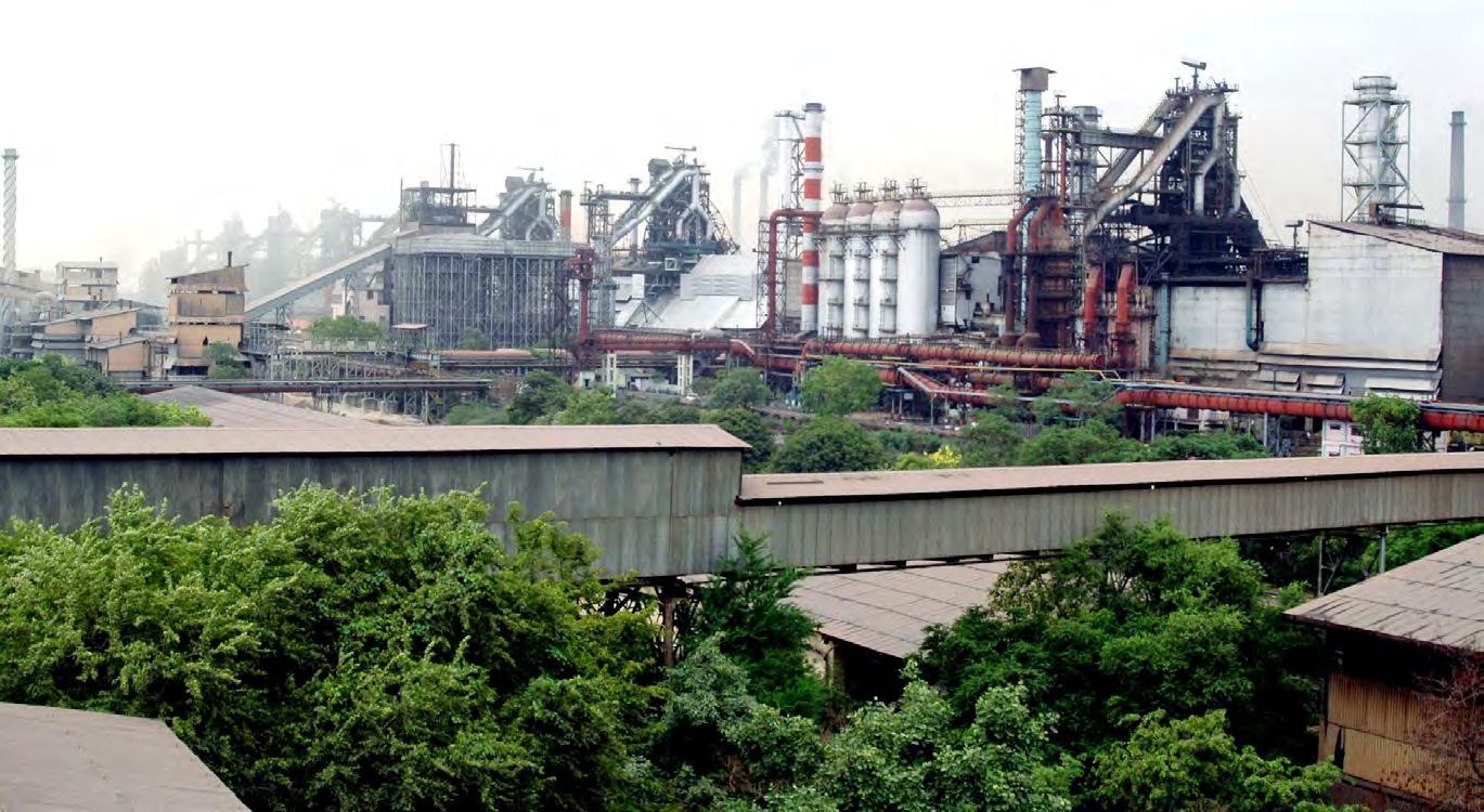
The Wire Rod Mill (WRM) at Bhilai Steel Plant of Steel Authority of India Limited (SAIL) is a 4-strand continuous mill comprised of a charging area, pusher-type reheating furnace, common Roughing Group (RG) (Stands 1-9) & first Intermediate Group (IG) (Stands 10-15) stands. The mill is then divided into four strands—A, B, C & D—capable of delivering quality finished product at high speed. In RG & Intermediate IG, four billets are rolled simultaneously. The mill design is highly complex, as
are the controls. Over the years, the mill’s finishing strands have been selectively modernised. No interventions were planned in the charging, furnace, RG, IG sections, as these arterial sections cater to the entire mill and would require a full production shutdown. However, the downtime, difficult fault diagnostics, obsolete measurement system and general under-performance of this primary area affected the mill’s performance. In response, measurement and automation systems were designed and selectively introduced to help improve the mill performance at an optimised capital investment and minimal mill shutdown.
Automation schemes for billet charging and feeding sections
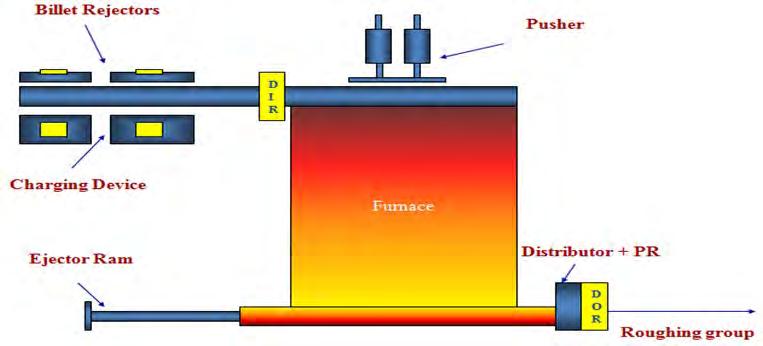
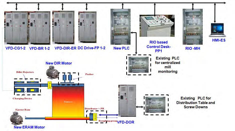
Mill Layout The Mill comprises a solid hearth reheating furnace, and only one billet is discharged from the furnace at any time. The furnace entry side charging equipment comprises 2 Charging Grates (CG) and corresponding Billet manipulators with Rejectors (BR), Draw In Roller (DIR), Roll Tables (RT) sections 1-4, Furnace Pusher (FP), Ejector RAM and Displacement (ERAM). The exit of the furnace features a Billet Distribution Table (DT), Draw Out Roller (DOR) and Pinch Rolls (PR). The furnace has a capacity of 170 billets, and the rolling is carried out at a rate of approximately 120 billets per hour. Cold billets from the billet mill are placed on CGs 1 and 2 with a magnet crane. The CG is operated by the operator, placing the billets on Roll Tables 1-4. Defective billets are removed with BRs 1 and 2. RTs 1-4 move the billets through the DIR, to feed the billets into the Pusher-type furnace. The Twin Pusher FP 1-2 pushes the billet forward towards the furnace exit door. The heated billet just in front of the Furnace Exit door is pushed out of the furnace with ERAM. This billet is drawn out into the 4-strand rolling stand with the help of DT, DOR and PRs for rolling in the RG. (Figures in Slide 2)
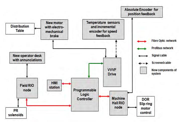
Upgradation of Charging equipment controls The charging section is comprised of outdated equipment and control systems installed when the mill was commissioned. Frequent system breakdowns and time-consuming diagnosis affected the operation of the entire mill, as the section is an arterial segment for all the strands. A revamp of the outdated control architecture was designed and carried out using a state of the art control system to increase mill availability, eliminate safety hazards and provide improved operational and maintenance management. The integrated automation system is designed with Digital AC and DC Drives to replace the contactor control scheme, a PLC with FO-based industrial network backbone instead of relay logic, new AC motors to replace select DC motors, new ergonomic operator desks and human-machine interfaces. All required coordination between the Charging Grate section operators, the Furnace Pusher operator and the Ejector RAM operator have been simplified through built-in algorithms and interlocks in the new PLC system, eliminating poor coordination and operation. (Figures in Slides 4, 5, 6)
Improvised billet length measurement scheme The billets are placed on charging tables by crane before moving to the roll table section to be fed into the furnace. Billets that are defective or too long must be identified and removed from the roll table by the billet rejector mechanism. Each charging grate has one billet rejector. Long billets were identified manually in practice, which sometimes led to oversized billets not being identified and being fed into the furnace. While pushing these billets into the furnace, they would get stuck in the furnace door leading to delays, damage to the refractory and hampered production. An improvised online billet length measurement facility has been designed using LASER based sensors. (Figures in Slide 8)
Precise positioning of billet distribution table and reliable control system Upon discharge from the furnace, billet feeding into the four strands is accomplished with a Draw Out Roller (DOR), Distribution Table (DT) and Pinch Rolls (PR). DOR is a single roller at the bottom of the roll table. There are four
Pinch Rolls (A, B, C, D), one for each strand, which grasp the billets from above, pulling them into the corresponding strand in Stand 1. The billet is positioned into a strand by the DT. All these operations, along with billet charging side coordination, are carried out from Operator pulpit PP2. Continuous and fool-proof operation of these mechanisms is a must for mill operation, which necessitated a highly accurate alignment of the distribution table with the stand 1 entry guide to prevent cobbles and misfeeds and ensure 100% availability of equipment. In the existing system, the distribution table was positioned through an outdated contact CAM switch-based method which did not deliver the desired accuracy and repeatability in positioning and required frequent maintenance and adjustments to achieve proper positions. The electrical equipment was based on slip ring AC motors and a relay logic system. The desk for operating the table, draw out roller, pinch rollers, strand bypass, other auxiliary controls for furnace door operation, permission for billet pushing, etc., was hardwired to relay panels in machine halls. The system was completely revamped to PLC-based control and industrially proven speed & position feedback sensors, as well as a new control desk, inverter grade motors and AC drives. Complete logic for operation of the Distribution table including calculation of instantaneous table position, calculation of speed setpoint for motor, the logic of operation in case of bypass of different strands and other appropriate interlocks have been incorporated to ensure fool-proof system operation. (Figures in Slide10,11,12) PLC-based control for Mill setting mechanisms of Stands 1-15 The roughing and intermediate groups of the mill are comprised of stands 1-9 and stands 10-15. The stands are individually and manually set for rolling, based on the desired pass schedule. To set the stands, each stand has two Screw Down (SD) mechanisms at the top left and top right, and one Stand Displacement (DISP) at the bottom. The stands are set for rolling from three independent posts. In the existing scheme, all the commands switches from the posts were connected using multi-core cables to hardwired Relay Logic based control panels in machine halls through congested cable galleries which were prone to fire hazards and earth faults.
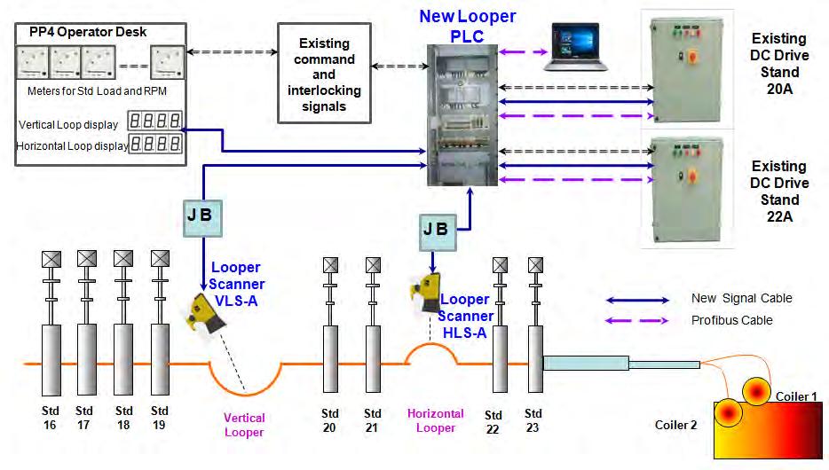
The control system for these mechanisms was also upgraded to a PLC & network-based system. The existing schemes that had no feedback or diagnostics features were reinforced with motor protection components. State of the art looper control system for A-Strand Loopers are critical for proper rolling and maintaining dimensions of wire rods. The enhancements in the product basket at the Wire Rod Mill of Bhilai Steel Plant meant that the existing looper control schemes of Strand A needed to be upgraded to cater to the requirement of increased range of loop formation and rolling temperature flexibility. The standalone, analogue controller and obsolete IR Loop scanners were replaced with a new looper measurement and control scheme for the strand’s vertical and horizontal loopers. The new system is based on state of the art Loop Scanners with configurable scanning angles to enable the use of the same sensor for both locations, optimising the inventory and sensitivity adjustment to facilitate reliable detection of the metal at different rolling temperatures. The PLC-based control loop system tracks the metal using proprietary SAILPHOS HMD sensors at different points. Calculation of setpoints for Loopers is then carried out based on angle feedback from scanners, interface done with all interlocks, and the speed of the finishing stands is controlled. On-line displays of the looper angles, finishing stand speeds & loads and status of all interlocks have been provided on the operator desks and the control panel for enhanced operation and maintenance management. (Figures in Slide 14)
Enhanced operation & maintenance management schemes In a rolling mill such as a Wire Rod Mill, operations & controls are complicated, with a large amount of equipment and mechanisms widely distrib-
uted over several pulpits, machine halls and control rooms. A lot of inter-pulpit coordination is required during operation through proper communication about the state of rolling equipment, status and position of billets, etc. Instantaneous information about equipment status is also necessary to identify and eliminate faults as soon as possible. An integrated automation architecture, coupled with information systems, is considered a necessity in today’s scenario. The successful implementation of such systems also depends on the reliable availability of information from the lower levels in the automation hierarchy. Information regarding the status of equipment and operation must be instantaneously available under a single window at strategic places for coordinated operation. This is especially important because the rolling is carried out at a very high speed with multiple billets in the line simultaneously. In the event of failure of any in-line equipment, the status should be instantly known and corrective action taken to reduce downtime. Information about facilities for lubrication, cooling, furnace, cranes and other auxiliaries is also essential for maintaining the desired productivity and quality levels. To further enhance the performance of the mill, improvised monitoring systems were designed and introduced. The facilities were based on customised Mimics Displays and Human Machine Interface (HMI) stations. Instantaneous status of all major equipment, mechanisms and parameters from charging to the intermediate stands are available. The system also provides important rolling and process information as well as the status of important utilities across the shop such as hydraulic and lubrication systems in the Roughing Area, Finishing Strands, Critical Power Supply Systems, Strand wise Rolling Count, Furnace operating parameters, metal-tracking, permission information, and stand loading during rolling of different sections & sizes. The centralised monitoring schemes have enabled efficient operation and maintenance management in the shop. (Figures in Slide 16, 17, 18)
Benefits accrued
The modifications to the mill have been carried out over the last five years, and each of the systems has yielded significant technological benefits in the areas concerned. Overall mill performance has witnessed gradual improvement in terms of reduced downtime through reliable control and automation schemes, better diagnostics and maintenance management, improved rolling rate, reduced generation of cobbles as well as improved energy efficiency. The contribution in terms of techno-economic benefits amounts to a 10% increase in annual production through reduction and controllable delays and improved mill availability, thereby boosting productivity.
www.velco.de www.velco.dewww.velco.dewww.velco.de www.velco.de
Technologies for Technologies forTechnologies for electric steel plants electric steel plantselectric steel plants
Forming of foaming slag Forming of foaming slagForming of foaming slag
Injection installations for fine carbon with Injection installations for fine carbon with Injection installations for fine carbon with 1 – 4 conveying lines 1 – 4 conveying lines1 – 4 conveying lines
Installations for injection of filter dust, Installations for injection of filter dust, Installations for injection of filter dust, additives etc. into furnaces or ladles additives etc. into furnaces or ladlesadditives etc. into furnaces or ladles
Pneumatic addition of lime Pneumatic addition of limePneumatic addition of lime
Injection of coarse lime via the furnace roof Injection of coarse lime via the furnace roof Injection of coarse lime via the furnace roof for the protection of the hot spots for the protection of the hot spotsfor the protection of the hot spots
Refractory repair systems Refractory repair systemsRefractory repair systems
Slinger machines, gunning machines and Slinger machines, gunning machines and Slinger machines, gunning machines and gunning manipulators for the quick and gunning manipulators for the quick and gunning manipulators for the quick and effective repair of EAF and ladles etc. effective repair of EAF and ladles etc.effective repair of EAF and ladles etc.
Gunning manipulators for RH-degassers Gunning manipulators for RH-degassersGunning manipulators for RH-degassers
VELCO - Gesellschaft für Förder-, Spritz- und Silo-Anlagen mbH VELCO - Gesellschaft für Förder-, Spritz- und Silo-Anlagen mbHVELCO - Gesellschaft für Förder-, Spritz- und Silo-Anlagen mbH Haberstraße 40 · D-42551 Velbert · GermanyHaberstraße 40 · D-42551 Velbert · GermanyHaberstraße 40 · D-42551 Velbert · Germany Tel. +49 2051 2087-0 · Fax +49 2051 208720 · E-Mail: info@velco.deTel. +49 2051 2087-0 · Fax +49 2051 208720 · E-Mail: info@velco.deTel. +49 2051 2087-0 · Fax +49 2051 208720 · E-Mail: info@velco.de


Automated Coil Trimming System for Wire Rod Mills in the Digital Era
Final material properties of coiled rod is one of the most important aspects of product quality in a long rolling mill. The rolling process itself produces wire with differing properties at the head and tail of each coil. While advancements in water cooling technology have reduced the number of head and tail rings that may not match the main body of the coil’s tensile values and metallurgical properties, they are still produced and need to be removed before further processing. Alternatively, coils with too many rings removed impact the mill’s process yield. A new patent-pending approach responds to this coil trimming challenge.
AUTHORS: Sudhakar Teegavarapu, Matthew Palfreman, William Shen and Jason Zelle, Primetals Technologies USA LLC
CONTACT: Rainer Schulze, Tel. +49 9131 9886-417, rainer.schulze@primetals.com
Coil ends need trimming
Coil end rings cool faster compared to the rest of the coil as it moves on the cooling conveyor, so the ends of coiled rod possess mechanical properties inconsistent with the body of the coil. These differences in
Smooth rings Scaled rings
Figure 1 Coil end rings with low surface quality Figure 2 High speed shear location
metallurgical properties present as low surface quality for certain grades of steel being rolled, as shown in Figure 1, sometimes referred to as “bubble scale.”
In addition, the presence of tension/ compression in the mill during rolling can mean front and tail ends are usually out of size tolerance. In order to deliver quality product to end customers and also meet internal and industry standards, a typical rolling mill would trim and scrap these coil end rings before shipping to customers.
The trimming operation needs to be located after the end of water and air cooling to ensure metallurgical properties are well-established, and surface defects can be easily identified.
Standard coil trimming systems
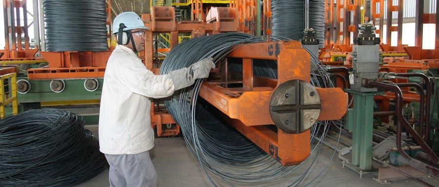
There are currently two approaches to trimming the coil in a wire rod mill. The first is the use of high-speed trim shears, generally positioned before the laying head and after quenching, as shown in Figure 2. The second method is the manual trimming operation, generally carried out downstream in the coil handling area at a dedicated trimming station, as shown in Figure 3. This is a mundane, repetitive task that can lead to strain and other injuries, lack of attention to detail and mistakes.
The automatic trimming system
When developing a robust, repeatable solution to the challenges associated
Figure 3 Operator counting rings prior to trimming
with accurate material removal from wire rod coils, it was paramount to preserve the quality of the finished product. This meant that whatever method of material removal would be employed, it must take place after the cooling conveyor and determination of the material’s final metallurgical properties
In order to trim the correct amount of material from the head and tail of each wire coil produced, a system would be needed that could detect and count individual rings of the coil, move to a defined position, cut the coil and remove the waste in a safe, efficient and repeatable fashion. Given the recent developments driven by digitalization, vision systems and automated functions, it is possible with the correct process to link a vision system directly to an automated function to accurately distribute, count, cut and discard waste material, with a repeatable accuracy that far exceeds an operator’s ability or the ability of a high-speed shear.
System components
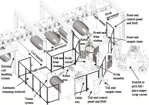
The patent pending coil end trimming system (TrimRob) consists of two vision-guided robots, one for each end of a coil. The coil handling area, before the coil compactors, where manual trimming operations are typically stationed, is an ideal location for such a system. A typical TrimRob system layout is shown in Figure 4. The layout needs to be custom designed for a mill, depending upon the type of coil handling system, coil transfer system for tail end trim, and the available floor area.
Vision system
At the heart of TrimRob is the vision system. It consists of cameras with an associated vision process software. The cameras can be mounted on an independent stand, as shown in Figure 4, or on an existing coil handling structure. They are enclosed in a special climate-controlled box to protect from heat, scale, and dust. Two cameras are mounted a set distance apart to cover an overlapping field of view. The coordinate systems of the cameras and the robots are synchronized through a calibration process. The vision process is designed to count rings starting from the end of the coil and output the (x,y) coordinates of the desired number of rings to be cut. The vision system hardware could be standalone or built into the robot controller. The cameras take snapshots of the coil at various points in the TrimRob program.
TrimRob workcell
The robotic workcell is designed according to the industry standard ANSI/RIA 15.06-2012 [1]. All components of the TrimRob system are enclosed in an eight-foot-tall, see-through mesh guard fence as shown in Figure 4. Safe distances from the robot and moving parts are maintained according to the standard. Movement of a coil in and out of workcell is controlled through smart safety light curtains. Specific areas within range of the light curtains are muted for the coil to pass through, at the same time sensing entry of operators into the workcell. The robot goes to safe position or stops instantly, depending on the type of trigger. Access gates are provided with a push button access, allowing the operators to enter the workcell safely for maintenance or other reasons.
Robot arm and controller
Six axis industrial robot arms are used for trimming, as shown in Figure 5. Maximum payload of these robots exceeds the weight of the end effector and force required to spread rings. The range of motion is mechanically locked for added safety to avoid accidental movement outside the required area.
Figure 4 Automatic trimming robotic workcell typical layout Figure 5 Robot arm with end effector
The hydraulic pump system can be mounted on axis 1 casing and hoses routed through a dresspack to the end effector. The hydraulic valve and control system along with the dresspack can be mounted on axis 3 arm and/or casing of the robot mechanical unit. Each robot has an individual controller unit and a handheld teaching pendant. Cables from the robot mechanical unit, vision system, HMI, and teach pendant are plugged into the robot controller. These cables can be routed through a trench or a walkable cable tray to avoid tripping hazards. The controller is located outside the guard fencing and next to an access gate.
Coil transfer for tail end trim
Regardless of a vertical or horizontal coil handling system, the coil needs to be transferred to an intermediary holding structure to trim tail ends. Figure 4 shows a coil transfer hook installed in a pit for a horizontal coil handling system. Other types of coil transfer system can also be integrated into the TrimRob workcell, as per mill’s requirement. The safety light curtains are muted for the coil transfer to pass through during a trimming cycle.
Scrap removal system
The robots trim a specific number of rings from both ends of coils depending on the size, grade, and customer requirements. These trimmed scrap rings need to be removed from the TrimRob workcell at regular intervals. The turntable scrap removal system shown in Figure 4 is one among several options. Three scrap carriers are placed on the turntable at a 120-degree angle, separated by guard fencing. The front end and tail end robots can independently deposit scrap on the carriers, while a forklift replaces them at the same time. A low height swing gate next to the turntable allows a forklift to replace the scrap carriers without interfering with operation of the TrimRob. This scrap removal system, as designed, seems to be most efficient in terms of timing sequence requirements.
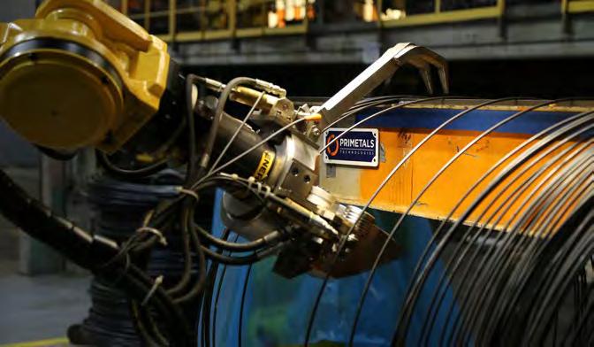
End effector tool
The trimming end effector tool (TrimTool) is mounted on the wrist of the robot mechanical unit as shown in Figure 5. The TrimTool consists of a cutting head, a pinch roll assembly for sample cuts, and an arm clamp for holding the scrap rings. All actuation functions as part of the TrimTool are driven by hydraulics. Design of the TrimTool is optimized to keep weight to a minimum, while isolating reaction forces away from the robot’s wrist. The replaceable cutting blades can trim rod products up to 28mm diameter. The TrimTool is universal, making it possible to use the same design for both front and tail end trimming, which simplifies spares.
Sample collection system
Rod mills typically test physical and mechanical properties of their product at regular intervals to meet quality requirements. TrimRob automates sample collection along with trimming. Figure 4 shows a sample chute, which is essentially a slide with one end extending into the TrimRob workcell, while the other end is bolted down to the floor outside the workcell. The length of samples to be collected dictates the angle and width of the sample chute.
Human Machine Interface (HMI)
The TrimRob system has a customized HMI that acts as a bridge and ties together the mill coil handling, coil transfer, scrap removal, robots, hydraulic, and safety systems. The HMI has the master program that governs operation of entire TrimRob system. It also has a safety PLC that monitors and activates the safety-related features.
Installation
Whether the coil orientation in the system is horizontal or vertical, the system can be easily retrofitted within the confines of an existing coil handling system with minimal impact to the existing equipment and process cycle. The robot mechanical unit is mounted to a baseplate that can be installed on the existing concrete floor using expansion bolts. Turntables, scrap chute, and safety fencing can also be installed directly using expansion bolts. The TrimRob system is designed to minimize civil foundation work. Walkable cable trays instead of trenches eliminate the need for excavation.
TrimRob process
Although the process of automated trimming is flexible and may vary from mill to mill, a typical TrimRob process is detailed below. Obtaining information on the number of rings to be trimmed is the first step in the TrimRob process. There are four possible means of communicating this information to the TrimRob HMI: 1) Manually enter the number of rings to be trimmed for a particular run. 2) Send that information to the Trim-
Rob HMI through the mill PLC by calculating the time taken for waterboxes to turn on after the rod entered. This time can be converted to length of rod and in effect number of rings to be trimmed. 3) Count rings that were not cooled according to specifications, when they are laid down on the cooling conveyor. A vision camera mounted on top of the conveyor can identify the color difference between uncooled and cooled rings and count the uncooled rings. This information can be passed on to the
TrimRob through Ethernet. 4) The ideal method is to use a vision camera mounted directly on the robot to identify the difference in
Figure 6 Snapshot from a typical vision process
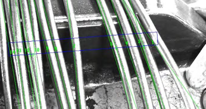
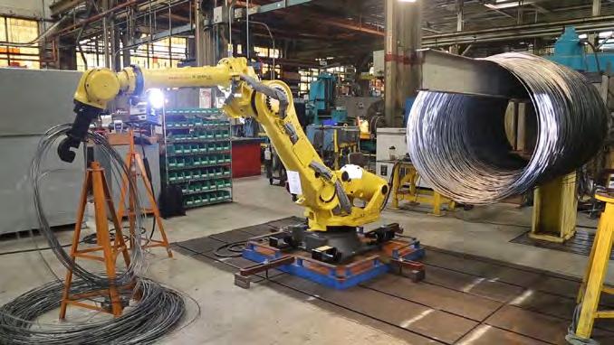
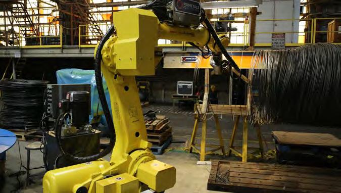
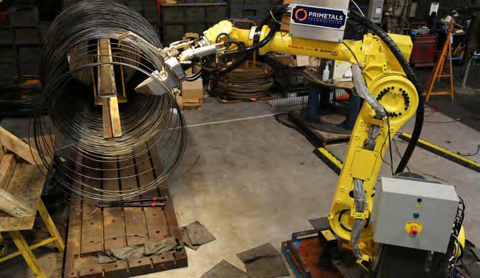
Figure 7 5.5 mm diameter product coil on TrimRob test facility
surface quality of cooled and uncooled rings. However, this method might not be suited for all grades of steel being produced. At the beginning of the trimming process, the robot is in home position, having completed the previous trim cycle. Once a new coil enters the TrimRob workcell, a proximity sensor mounted on the coil handling structure indicates that the hook is in position for trim. This triggers the vision camera to take a snapshot that can identify the end ring of the coil. Figure 6 shows a snapshot from a typical line locator vision process. As can be seen, each line closely represents a ring. The robot maneuvers to penetrate the coil with the cutting head of the TrimTool. The TrimTool moves towards the open end of the hook to spread the rings. The vision camera takes a snapshot and locates the ring to be cut based on information from the HMI. After positioning and penetrating the coil next to the ring to be trimmed, the latter is guided into the cutting chamber of the TrimTool.
After the specific ring is cut by firing the main cylinder, the clamp closes to grab all scrap rings. The robot maneuvers to remove the scrap rings from the REFERENCES
hook and carries them over to the sample chute. While the robot is in motion, the sample pinch roll rotates to pull through a predetermined length of the rod. The main hydraulic cylinder fires for the second time to cut the sample rod length. The cut sample slides down the chute and collects at the base outside the workcell for an operator to pick up. The robot maneuvers to the scrap handling system and drops the scrap rings on a carrier. The robot then returns to home position ready for the next trimming cycle. The entire duration of one trim cycle is approximately 45 seconds, which is close to the time a typical steel mill takes to make a coil.
All system actions and functionalities are fully automatic and require no human interaction. The vision system is configured to recognize interlaced rings during the ring spreading process. There is a predefined process carried out by the robot using the end effector to remove them. There is also a process to overcome buried front and tail end rings that can occur during coil formation and handling.
Proof of concept
Primetals Technologies USA LLC commissioned a fully operational robotic test bench at its Worcester, Massachusetts, USA facility, as shown in Figure 7. Closely replicating steel mill conditions for accurate and reproducible results, extensive testing and end effector prototyping resulted in a fully automated, repeatable and accurate trimming process. The test bench consists of a vision-guided robot mounted on an adjustable base. Several kinds of cameras, mounts, and lightings were available for testing various applications.
There is a viable alternative to the current high-speed shear systems for automated trimming of wire rod coils. The system is less intrusive, less maintenance- and process-intensive, and utilizes state-of-the-art equipment that is well proven in other industries, including foundries and steel making. The system is self-contained, accurate and repeatable, and provides the best quality final wire rod with its location after final metallurgical properties are defined. More importantly, for those mills that cannot fit a high-speed shear or have doubts about its use, there is now an alternative solution that removes the need for operators to work within a congested, hazardous area.
1. ANSI/RIA R15.06-2012 American National Standard for Industrial Robots and Robot Systems- Safety Requirements (revision of ANSI/RIA R15.06-1999) https://webstore.ansi.org/Standards/RIA/ANSIRIAR15062012
Construction of new European wire rod mill still on hold
Dutch company Van Merksteijn International (VMI) in 2018 placed an order with Danieli to supply the technical equipment. for the construction of a greenfield wire rod mill in the Netherlands. The project was temporarily suspended last year, after troubles with necessary permits due to nitrogen issues, a largely local matter as a result of a recent verdict is¬sued by the Dutch Council of State, but also general insecurities concerning potential carbon dioxide taxes. Van Merksteijn recently signalled that the debates with the local authorities are close to completion, and that construction could be resumed soon. The Dutch maker of wire and wire mesh has long been protesting against a shortage of wire rod for independent processors in Europe, which forces it to import large volume (see box). The complete project will include scrap-based steelmaking with an electric arc furnace, and a wire rod rolling mill. VMI has chosen the port of Eemshaven in Groningen with an area of around 50 hectares. The capacity of phase one will be up to 900,000 tonnes of wire rod. It will be a “… green steel mill,” that will meet all strong environmental standards in the northern Netherlands, the company said upon announcement oft he project. The total investment is estimated at around €260 million.
EU industry association fights for wire rod exports

Four years ago, a group of non-integrated European processors of wire rod founded EUNIRPA, the European Non-Integrated Wire Rod Processors Association, with the aim of maintaining wire rod imports from non-EU countries, given a lack of material supply from within the European Union. EUNIRPA’s initiator is Kris Van Ginderdeuren, managing director of Van Merksteijn International in the Netherlands. EUNIRPA on several occasions has since been in discussion with the association of European steelmakers in Brussels, Eurofer, the driving force of trade restrictions for imports to the EU. Given the notorious shortage of wire rod in the EU, imports from non-EU countries are basically the only alternatives available in commercially acceptable quantities, EUNIRPA argues.
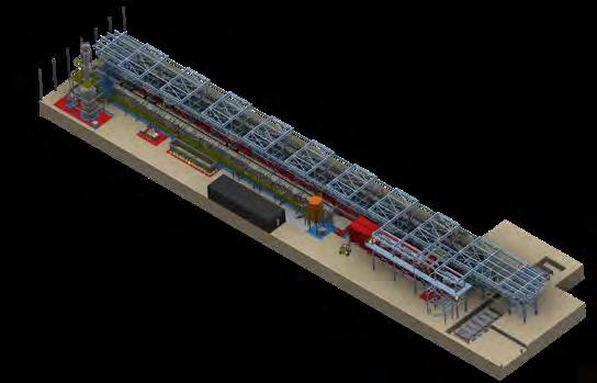
Steuler builds world’s largest pickling plant for steel wires
Steuler Anlagenbau, a medium-sized engineering German company, is currently building a fully automatic tunnel pickling plant for steel wires for German wire manufacturer Westfälische Drahtindustrie (WDI), based in Hamm, North Rhine Westphalia. The new pickling plant will have an annual capacity of approximately 550,000 tonnes of different grades of carbon steel, making it the largest continuous pickling plant in the world once it has been commissioned, the plantbuilder claims. WDI, had not originally planned this investment in a new plant – around Easter 2019, welding work caused a major fire in Hamm which completely destroyed the existing 40-year-old pickling plant and made an urgent replacement necessary. According to Scheuler, the order is worth more than €10 million.
Polish-German cooperation strengthens presence in wire industry
EJP WIRE Technology GmbH, and Italmec Sp. z o.o in have entered a strategic alliance with the aim to supply the wire processing industry with complete plants to produce carbonaceous wires. With the drawing lines from Poland’s Italmec and the cleaning systems from Germany’s EJP WIRE Technology, previously known as EJP WITEC GmbH, the companies now offer complete production lines for the entire process chain from wire rod to finished coil. Among other things, they are thus closing the gap that was created this year by the insolvencies of well-known German manufacturers of wire rod machines. Founded in 2006 by Daniele Costantin in Katowice / Poland, Italmec Sp. z o.o. is focused on the production of straight-line drawing machines in all common sizes. The product portfolio also includes process technology and machines to produce welding wires of all kinds. The product range of EJP WIRE Technology, based in Schwerte, complements the range with equipment for mechanical cleaning of wire surfaces. Ist parent EJP Maschinen GmbH makes blasting systems and butt-welding machines. In addition to machines and systems to produce rods, tubes and profiles, the company now also produces systems for the wire industry at its main plant in Baesweiler near Aachen. Jacques Paraskevas, managing director of EJP Maschinen GmbH, sees great benefits for his customers in the cooperation: “The product ranges of the three companies complement each other ideally. For example, wire manufacturers now have a single contact for the entire process chain of drawing and treating wire.“ Lothar Köppen, managing director of EJP WIRE Technology, has known the wire industry for over 35 years: “The company is young, but our employees have many years of experience in the production and treatment of wire - they know what it’s all about“.
MANNESMANN H2READY MANNESMANN H2READY
HFI-Welded Steel Pipes for the Transportation and Storage of Hydrogen
The increased use of hydrogen calls for corresponding infrastructure for the medium’s transportation and storage. This creates enormous demand for new gas pipelines suitable for hydrogen conveyance. „Mannesmann H2ready“ steel pipes from Mannesmann Line Pipe offer maximum flexibility and safety for the transport and storage of gaseous hydrogen and of hydrogen admixed to natural gas.
Hydrogen is available in almost unlimited supply and is ideally suited as an energy carrier for the transport and storage of renewable energy. Power-to-gas technologies make energy usable where it is needed. The safe transport of hydrogen plays a central role in a future with an increasingly renewable energy mix. In a simulation of a hydrogen network infrastructure with mass-storage facilities for Germany, the possible future scenario looks like this: for the complete conversion of mobility to hydrogen as an energy source by the year 2052, with 33.9 million fuel-cell vehicles, 9,450 H2 filling stations would be required nationwide.
Since hydrogen technology is also being seriously promoted in countries with extremely high traffic density, such as the USA, Japan, China and India, new pipelines are needed. High-frequency induction-welded “Mannesmann H2ready“ line pipe from Mannesmann Line Pipe, with chemical, mechanical and geometric properties specially adapted to the transport of hydrogen, is ideally suited to the imminent expansion of pipeline capacity. Proven welding technology and the use of modern steel grades resistant to the corrosive effect of hydrogen make its line pipe a cost-effective and environment-friendly solution, the company claims.
Critical tests passed
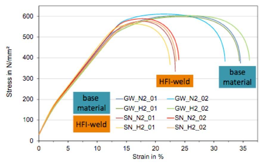
Steel pipes from its division Mannesmann Line Pipe offer maximum flexibility and safety for the transport and storage of gaseous hydrogen and of hydrogen admixed to natural gas. Previous tests and existing standards already show that the use of line pipe grades up to API 5L X52 (L360) is non-critical, even if there are restrictions on the alloy content (EIGA Guideline, DVGW tests, EU project NaturalHy). The behaviour of higher-strength materials of grade X70 (L485) was tested on exposure to pure compressed hydrogen and hydrogen/natural gas mixtures in slow strain rate tensile tests at 80 bar. Neither the base material nor the HFI weld or standard girth weld showed signs of increased susceptibility to hydrogen in the structurally relevant area. The group’s own research institute, Salzgitter Mannesmann Forschung, was involved in the testing and realisation of the quality standards.
The company states that the mechanical properties of its steel pipes exceed the requirements of the European Industrial Gases Association, (EIGA), and guarantee optimum safety and service life.
The mechanical material properties of Mannesmann’s pipes are designed for transporting hydrogen. They present clearly defined strength levels in quasi-static tensile tests. Even in the longterm result, slow strain rate tensile tests show no negative influence of hydrogen on our “Mannesmann H2ready” steel pipes.
Utmost corrosion resistance

For lasting durability in hydrogen transport, the inner surface is free of any discontinuity (in accordance with ISO 3183). Furthermore, internal points which are vulnerable in relation to hydrogen are reduced to a minimum by the phosphorus and sulphur content levels being guaranteed to remain below those specified in the EIGA guideline. A carbon equivalent that has also been further reduced ensures excellent weldability of our pipe material. This guarantees a long service life and leads to low-maintenance operation. In order to achieve greater freedom in pipeline design, Mannesmann offers grades up to X70 (according to API 5L) or L 485). If required, suitability for the hydrogen atmosphere (e.g. 100 bar, room temperature, 100% pure gaseous H2) is proven in a comparative test for the application.
Innovations in energy storage and transportation are therefore decisive for a successful energy transition. In the power-to-gas sector, hydrogen in particular is proving to be an excellent medium. New fields of application can be found, for example, in the conversion of electricity, the heat market, automotive industry (fuel cell technology), steel industry, glass industry, chemical industry and food industry.
Especially in Germany, increasing the use of hydrogen makes good sense
Stress-strain behavior in slow strain rate tensile test of X70 in 100 % hydrogen (H2) compared to an inert nitrogen atmosphere (N2) on base material specimens (GW) and HFI weld specimens (SN).
for several reasons: • The country has over 100 years’ experience of the commercial handling of hydrogen • It ranks among the group of global leaders in the development of H2 and fuel cell technologies • There are salt caverns for large-volume H2 storage in northern Germany • Energy-intensive premium steel production and further processing
Non-stop wind energy from the pipeline
As the energy carrier of the future, H2 only becomes truly environmentally friendly with the conversion of renewable energies (e.g. wind energy) into hydrogen. After that, the intended purpose is merely secondary. In terms of mobility, where hydrogen is used or is likely to be used for cars as well as for aircraft, trucks, buses, trains or ships, it is where it is needed quickly, safely and cleanly. With the Mannesmann H2ready pipeline.
Mannesmann steel pipes transport (wind) power in the form of hydrogen. Eco-friendly hydrogen can be produced using power-to-gas technology, as this involves the use of renewable energies (e.g. wind, sun). Water is split here into oxygen (O2) and hydrogen (H2) by means of electrolysis. The environmentally friendly hydrogen produced by this means serves as a chemical storage medium and can be reused as fuel or for reconversion into electricity. In addition, the power-to-gas process enables subsequent methanation, with which regenerative natural gas can be produced from the hydrogen downstream. Mannesmann’s H2 pipeline also enables the transport of conventional methane or gas which has largely been decarbonised by electrolysis and converted to hydrogen.
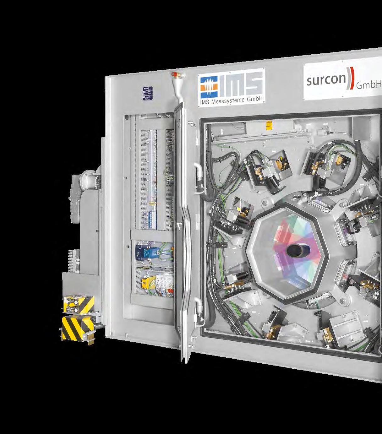
Surcon 3D Tube Surface Inspection system
Aprerequisite for the economical and future-oriented production of pipes is specific knowledge of the production process. In particular these are the product properties after each of the typically three forming stages. Only through precise, reliable and durable measuring equipment can the ever-increasing demands on the finished product “tube” in terms of uniformity and adherence to low tolerance limits be met.
Accordingly, the objectives are always the continuous recording and storage of all measured values, production parameters and system events, feedback of the measured values to the pre-control and / or tracking of the control equipment of the rolling units, support of the operator by targeted fault diagnosis and high availability of the measuring system.
In the 3D surface inspection system “Surcon 3D Tube”, IMS provides tube manufacturers with another high-quality inspection tool. The system enables you to detect surface defects at a much earlier stage of the rolling process than before and to counteract them early and effectively through precise corrective measures.
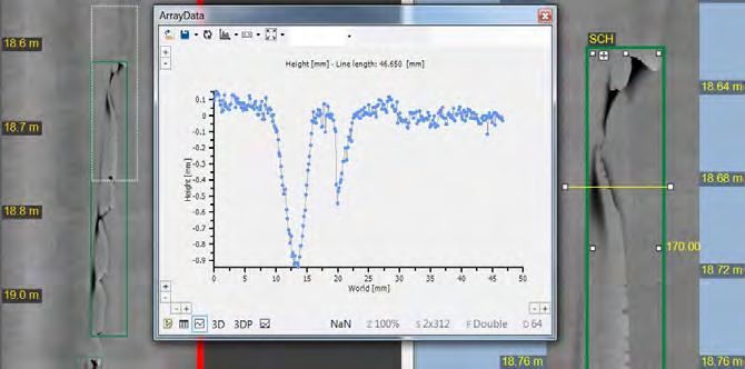
In particular, the three-dimensional information on the spatial extent of the defects enables far more reliable decisions to be made on the extent to which a surface defect can still be
Height profile of a defect in the form of a “shell” tolerated or whether immediate intervention in the production process is necessary.
In addition, 100% surface inspection ensures that immediate knowledge is available as to whether a detected defect occurs once, recurs several times on a tube or at the same length position from tube to tube – information that is almost impossible to determine reliably by manual inspection. Especially in tube production, surface defects are often perpetuated through the complete process chain. Non-stop surface inspection from bloom to finished tube is therefore critical for the quality of the final product.
Advantages of Surcon 3D Surface Inspection System: • Automatic detection and classification of defects and geometric data (including depth and position) • Detection of defects directly in the rolling process • Continuous acquisition of all measurement data, product parameters and system events

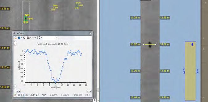
Height profile of a defect in the form of “scale“

Height profile of a defect in the form of “impression”
Archiving of the data for process optimization Substitution of manual inspection possible
The exemplary types of defects shown here as examples for seamlessly rolled tubes are only a selection of concise samples of how they can be detected with the help of 3D surface inspection on finished tubes of different dimensions. Depending on the error type, the cause of the error can be determined as quickly as possible
Height profile of a defect in the form of “washout”
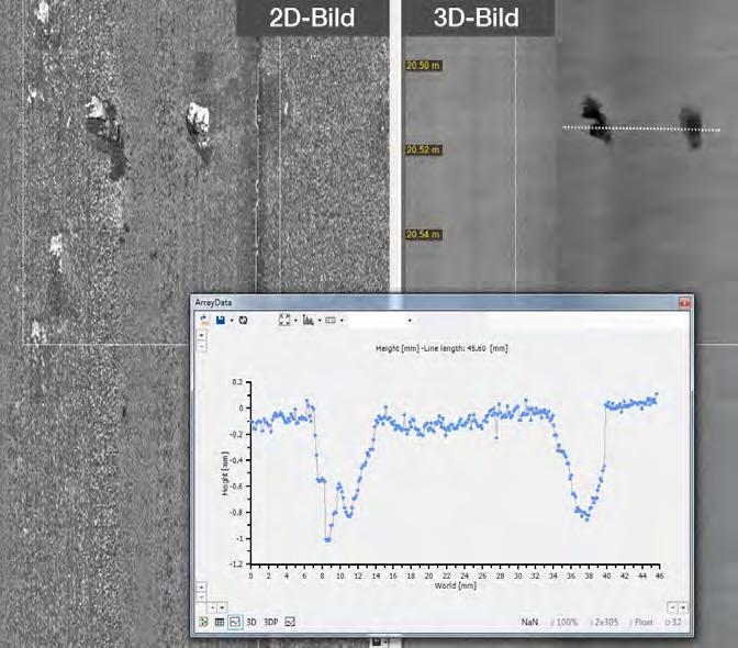
and a corresponding countermeasure can be taken, e.g. a change of roll stands if all the following tubes were rolled out with the same significant defects in the case of a roll breakage or bearing damage.
Steel Market Paradox: Supply Shortages in a Lull of Demand
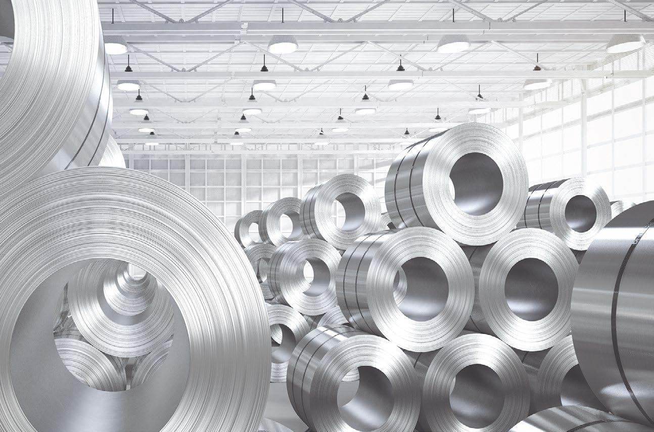
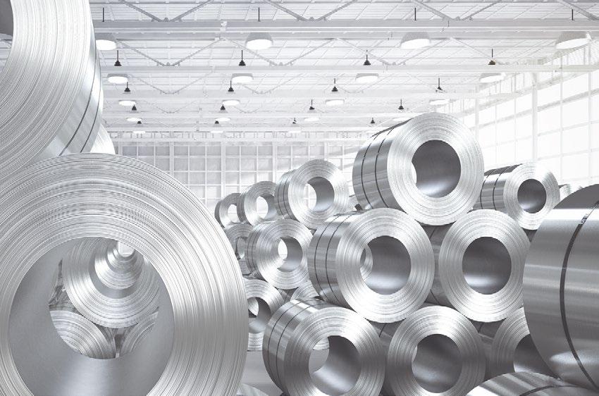
Steel processors cannot believe their eyes and ears: while the demand for steel in northwestern Europe has fallen to its lowest level in eleven years, buying coil has become a challenging job, German steel expert Andreas Schneider of Stahlmarkt Consult observes.
Reports of extremely long delivery times are mixed with concerns that the ordered quantities of steel will not be delivered on time. The cause of this is an asynchronous development of supply and demand in combination with declining import volumes. What initially looked like a brief summer episode has continued into late autumn.
In Germany, Europe’s biggest single market, steel demand this year is seen to fall below 30 million tonnes – compared with more than 40m tonnes in good years, last seen in 2017. The road out of this low will most likely be long and arduous.
Accordingly, there should actually be enough steel available to cover current demand. But feedback from the market indicates that this is currently not the case, especially for flat steel. The loudest complaints about supply shortages come from the automotive value chain. Delivery times quoted by steelworks already extend far into 2021, and additional requirements can often only be met with great difficulty. Steel buyers currenty face hefty price premiums on the spot market.
Supply and demand: recovery at different speeds
The reason for this paradoxical situation is that supply and demand have not been developing in sync for months. Production in some steel user sectors has recovered more quickly than was feared in the spring. This is particularly noticeable in the automotive and automotive supply sectors, which are benefiting from the strong performance of the Chinese market.
However, there can be no talk of a boom: even between May and September, car production and exports were more or less significantly below the previous year’s figures.
One explanation is that inventories were drastically reduced during the first Covid-19 lockdown period, so that the current need for restocking is driving repurchasing activity beyond the demand of downstream users. According to the statistics office, order intake at mills in August were approximately on the previous year’s level, although there has been not much of a recovery at industries like pipes or mechanical engineering.
The production of blast furnace-based oxygen steel, which forms the basis of flat steel production in Germany, is increasing less rapidly. In August and September approximately 16% less steel was produced on this route than in the previous year. This means that the slump suffered between April and July has only been recovered by about half. By contrast, the scrap-based electric steel plants already produced more steel in September than in the same month last year.
How much longer?
Not least in view of the upcoming contract and price negotiations for 2021, many market participants are asking themselves how long the unusual situation will continue. But the ball is first in the court of the EU producers. The question here is to what extent the mills are deliberately keeping supply tight in order to strengthen their starting position for price negotiations. The technical reasons often cited as the reason for the slow increase in production in the complex process of blast furnace control are convincing for a period of some weeks, but not over many months.
However, given the high costs of shutting down and starting up blast furnaces, it is understandable that such decisions should be taken with caution. On the other hand, the strained earnings situation of many manufacturers should provide a strong incentive to bring every profitable tonne of steel to market. Especially since there is a great risk that frustrated customers will sooner or later turn to suppliers from outside the EU.
In the not too distant future, structural oversupply will resume in the EU, and the supply problems will disappear. But the timing of this turnaround cannot be predicted accurately.
Annual figures of SMS group
The company is taking a look back at its miscellaneous activities in 2019/20. Its traditional engineering business has been augmented by preditive maintenance, artificial intelligence, digital documentation, and other features. We will report from the group’s (online) press conference.
Netherlands open recycling plant for contaminated steel scrap
Purified Metal Company (PMC) has developed a method of cleaning steel scrap contaminated from asbestos or other hazardous components like mercury, PCB or chrome VI.
Special coating protects steel from hydrogen ‘attack’
Atomic hydrogen often induces brittle behavior in metals at high temperatures. Institute Fraunhofer IWMhas now developed a robust coating that effectively protects steel from the penetration of hydrogen.

ADVERTISERS’ INDEX
Aumund Fördertechnik GmbH Friedrich Kocks GmbH & Co. KG F.I.M.I. S.p.A FrisorTec GmbH Georgsmarienhütte Holding GmbH Hydrowatt AG IMS Messsysteme GmbH Keller& Bohcek GmbH & Co. KG 35 52 23 21 33 36 45 37 Keller HCW GmbH Kuttner GmbH Maschinenfabrik Gustav Erich GmbH & Co. KG Micro-Epsilon Messtechnik GmbH & Co. KG NLMK Europe SMS Group GmbH
IMPRINT
MPT International is published by Maenken Kommunikation GmbH, Cologne/Germany. www.mpt-international.com
Publishing House:
(responsible for editorial, advertising, production and circulation) Maenken Kommunikation GmbH Von-der-Wettern-Straße 25 51149 Cologne/Germany www.maenken.com Phone +49 (0) 22 03/35 84-0 Fax +49 (0) 22 03/35 84-185
Frequency: 6 x per year Unit price: see cover, plus forwarding expenses
Publisher:
Dr. Wieland Mänken Phone +49 (0) 22 03/35 84-0
Executive management:
René Khestel
Publication Manager:
Wolfgang Locker
Head of Advertising:
Susanne Kessler Phone +49 (0) 22 03 / 35 84-116 susanne.kessler@maenken.com
6 28
7
9 13 2 Steuler -KCH GmbH The Coating Company Karl Diederichs GmbH & Co. KG Velco GmbH Wuppermann AG
Beihefter: Paul Wurth S.A. 43 51 11 34 48
Editorial Team:
Christian Köhl (Editor-in-Chief) Phone +49 (0) 22 03/3584-192 christian.koehl@maenken.com
Niklas Reiprich niklas.reiprich@maenken.com
Editorial address: mpt-international@maenken.com
Print Shop:
D+L Reichenberg GmbH Schlavenhorst 10 D-46395 Bocholt