
73 minute read
InSights
new trends, new techniques and current industry issues Formal concrete anchorage design provisions first appeared in ACI 318-02 as Appendix D, with applications limited to cast-in-place anchors and postinstalled mechanical expansion anchors. The codified design provisions represented a generic approach to anchorage design, which diverged from past design practice of using manufacturers design tables; these tables may or may not have represented all characteristics associated with an anchor’s design capacity. In 12 years, we have codified anchorage design procedures and developed anchor qualification standards that have greatly raised the reliability bar for anchors used in practical design conditions. So, what is the state of the anchoring industry and where do the codes go from here?
ACI 318-14
The new structural building code (ACI 2014) will be re-organized based on member type. Appendix Post-Installed Anchors D will now formally be placed in the body of the Code as Chapter 17. But unlike other chapters in The Present State of the re-organized Code, Chapter 17 essentially the Industry remained an untouched clone of Appendix D. This was a conscientious decision by the 318 Code By Neal S. Anderson, P.E., S.E. and Donald F. Meinheit, Ph.D., P.E., S.E. Committee at the beginning of the reorganization work, because: (1) the Appendix D anchor design provisions are still “relatively new” and (2) there was a desire to keep things the same, as the design profession and university classrooms are just getting familiar with the provisions. The next code cycle will contemplate further additions and layout reorganization.
Neal S. Anderson, P.E., S.E., is a Staff Consultant at Simpson Gumpertz & Heger Inc. in their new Chicago office. He is involved with anchorage issues through his participation on ACI 355 – Anchorage to Concrete, ACI 318-B – Reinforcement, and ACI 318 – Structural Concrete Building Code. Neal may be reached at nsanderson@sgh.com. Donald F. Meinheit, Ph.D., P.E., S.E., retired from Wiss, Janney, Elstner Associates – Chicago, is the past chair of ACI 355 – Anchorage to Concrete and member of ACI 318-B – Reinforcement. He has been involved with concrete anchorage issues throughout his career and is a frequent lecturer on the subject. Donald may be reached at dmeinheit@wje.com.
Adhesive Anchors
This anchor type was accepted by ACI 318-11 in a three-part acceptance format: Design Provisions Adhesive anchors were incorporated into ACI 318 under the premise that the existing design models would be minimally affected. Adhesive anchor design provisions for tension were the only provisions supplemented, necessitating new checks for concrete bond stress. Adhesive anchors loaded in shear behave similar to other post-installed and cast-in-place anchors, and, hence, existing design models and procedures could be used. Qualification For post-installed mechanical anchors, anchors must be qualified to the criterion in the ACI 355.2 standard (ACI 355 2007). Similarly, adhesives used in ACI 318-11 (2011) anchor designs
Figure 1. Undercutting of screw threads in concrete (from Olsen, et. al., 2012).
must be qualified in accordance with the ACI 355.4-11 standard (ACI 355 2011). ACI 355.4 is a comprehensive product standard for structural adhesives used for anchoring, modelled after the ICC/ES Acceptance Criteria (AC) 308 (2013). Due to improvements in the ACI qualification document, AC308 was recently revised to conform to ACI 355.4-11, to avoid having the anchoring industry work to two different standards for acceptance. Certification Based partially on the Boston Big Dig tunnel accident, the adhesive anchor installer must be certified to install anchors in certain orientations and under certain load conditions. This requirement is recognition by the ACI 318 Code committee that adhesive anchor installation needed some oversight qualifications to achieve satisfactory installations, consistent with the written design requirements and anchor manufacturer installation instructions. The success, or failures, of adhesive anchors are highly dependent on the installer and the procedures employed to install the anchor. Certification was deemed an important component of adhesive anchor usage, on par with certified welders for welding key structural steel connections. In addition to installer certification, inspection is an important requirement required in ACI 318-11. The ACI Code provisions are not mandatory unless adopted by the local building code for the given jurisdiction. For states and municipalities using the 2012 International Building Code (IBC 2012), IBC 2012 has adopted ACI 318-11 and ACI 355.4-11. However, the U.S. is under a stepped phase-in period for adoption of the design and qualification of adhesive anchors. As of 15 January 2014, the following actions were taken: • All adhesive anchor Evaluation Service
Reports (ESR) will reference ACI 318-11, Appendix D. This includes the design provisions for bond strength and concrete breakout.
• ESR’s also carry forth several of the code provisions for qualified installation personnel and inspection. As of 15 January 2015, the following will be required: • Testing referenced in the ESR’s by the manufacturers will conform to the revised AC308, which is essentially
ACI 355.4-11. There are many more nuances to the IBC 2012 and ACI codes referenced and the phase-in situation. Reference should be made to a paper by Hoermann-Gast (2013) for additional information.
Screw Anchors
There are a wide variety of post-installed concrete anchors, and the newest postinstalled anchor is the screw anchor. In reality, screw anchors have been around since the early 1990s. They are intended to carry direct tension, direct shear, or combinations of tension and shear loadings. Although the design procedure for screw anchors has not been codified, they are gaining acceptance in building practice as a reliable fastening element (Olsen, et. al., 2012). To provide the mechanical interlock to the concrete, the screw anchor cuts a thread into the concrete during the installation process. This makes the use of screw anchors a singleuse item; removing and reusing the screw anchor in the drilled hole is not advised because the cutting threads on the screw are worn and getting the screw threads into the original cut threads in the concrete is difficult. In Figure 1, the undercutting of the threads in the concrete is illustrated. The creation of the threads in the concrete gives the screw anchor some advantage in cracked concrete where a small-narrow crack intersecting the threads has only a minor reduction on tension capacity. Currently, screw anchors fall outside the scope of ACI 318-11 Appendix D and Chapter 17 of ACI 318-14, Anchoring to Concrete. In the next Code cycle, screw anchors will be studied for inclusion. Research testing of screw anchors has shown that failure can occur in tension via three modes: steel failure, concrete breakout failure, and pullout failure. Pullout failures look
ADVERTISEMENT–For Advertiser Information, visit www.STRUCTUREmag.org
Software and ConSulting FLOOR VIBRATIONS
FLOORVIBE v2.20 New Release
• Software to Analyze Floors for Annoying Vibrations • Demo version at www.FloorVibe.com • Calculations follow AISC Design Guide 11 and SJI
Technical Digest 5 2nd Edition Procedures • Analyze for Walking and Rhythmic Activities • Check floors supporting sensitive equipment • Graphic displays of output • Data bases included
CONSULTING SERVICES
• Expert consulting available for new construction and problem floors. Structural Engineers, Inc.
Radford, VA 540-731-3330 tmmurray@floorvibe.com very much like bond failures for adhesively bonded anchors. Pullout failures also occur for screw anchors only when they are deeply embedded. Deep embedments are often difficult to achieve because the friction of cutting a thread can exceed the torsional capacity of the screw shank and fail the steel in torsion. Consequently, it is recommended that screw anchors be used within a limited embedment depth, that is, 15/8 inches < hef < 11 da. A design procedure for screw anchors does exist; they can be safely designed using a procedure found in ICC/ES AC193 (2012). The AC193 design procedure follows closely the European design procedures in ETAG 001 (2013). AC193 also outlines the qualification tests required for screw anchors. The ACI qualification standard, ACI 355.2, is being updated to include screw anchor qualification testing.▪
The online version of this article contains detailed references. Please visit www.STRUCTUREmag.org.
Attention Bentley Users
Have you received your automatic quarterly invoice from Bentley? Would you like to reduce or eliminate these invoices? Use SofTrack to control and manage Calendar Hour usage of your Bentley SELECT Open Trust Licensing. Call us today, 866 372 8991 or visit us
www.softwaremetering.com
CADRE Pro 6 for Windows
Solves virtually any type of architectural structure for internal loads, stresses, displacements, and natural modes. Easy to use modeling tools including import from CAD. Element types include many specialized beams and plates. Advanced features for stability, buckling, vibration, shock and seismic analyses.
CADRE Analytic Tel: 425-392-4309

www.cadreanalytic.com
StruWare, Inc
Structural Engineering Software
The easiest to use software for calculating wind, seismic, snow and other loadings for IBC, ASCE7, and all state codes based on these codes ($195.00). CMU or Tilt-up Concrete Walls with & without openings ($75.00). Floor Vibration for Steel Bms & Joists ($75.00). Concrete beams with/without torsion ($45.00).
Demos at: www.struware.com
Wood Advisory Services, Inc.
Consultants in the Engineering Use of Wood & Wood-Base Composite Materials in Buildings & Structures
• Product Evaluation & Failure Analysis • In-situ Evaluation of Wood Structures • Wood Deterioration Assessment • Mechanical & Physical Testing • Non-Destructive Evaluation • Expert Witness Services www.woodadvisory.com
845-677-3091
Delivering Water unDer Pressure
By Stephanie A. Wong, P.E. S.E.
Figure 1. The slip joint was lowered into the vault by crane. Courtesy of San Francisco Public Utilities Commission, Robin Scheswohl.
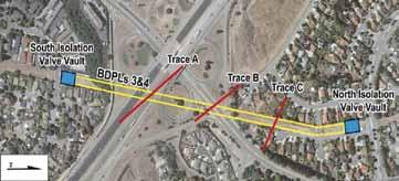
Figure 2. Hayward Fault Traces A, B, and C. Courtesy of URS Corporation.
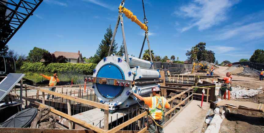
Installed between 1952 and 1973, the 78-inch and 96-inchdiameter Bay Division Pipelines (BDPLs) 3 and 4 are two of the major regional transmission pipelines in the San Francisco Public Utilities Commission’s (SFPUC’s) Hetch Hetchy Regional Water System. The system delivers water a distance of 167 miles from the Hetch Hetchy Reservoir in Yosemite National Park across California to the Bay Area, and supplies approximately 260 million gallons per day of drinking water to 2.6 million people in the San Francisco Bay Area. Water is critical to the economic viability of the Bay Area, and the public health and safety of those who live and work there. BDPLs 3 and 4 cross the Hayward Fault at the intersection of a major interstate freeway and a state highway in the city of Fremont on the east side of San Francisco Bay. The 2007 Working Group on California Earthquake Probabilities, made up of the U.S. Geological Survey and partners, estimated a 31% probability that an earthquake of magnitude 6.7 or greater would occur on the Hayward Fault by the year 2036. Studies by Geomatrix Consultants, Inc. (2004) and William Lettis & Associates (2008) concluded that a major earthquake could cause a significant fault displacement at the project site, which would result in certain rupture of both pipelines and extensive localized flooding and loss of water supply to the Bay Area. To address this area of vulnerability in the system, the SFPUC initiated a seismic retrofit program for the two pipelines to ensure that water delivery continues after a major earthquake.
The Program
The first phase of the seismic retrofit program included installing two isolation valve vaults on BDPLs 3 and 4 on either side of the Hayward Fault. This work, which was completed in 2007, provided the SFPUC with the capability of shutting down the pipelines quickly if they rupture at the fault, reducing the extent of flooding and property damage. The objective of the second phase of the retrofit program, the $78 million Seismic Upgrade of BDPLs 3 and 4 Project designed by URS Corporation (2011), is to ensure continuous delivery of water after a major earthquake. This project spans approximately half a mile between the two previously-constructed isolation valve vaults. The limited 80-foot-wide right-of-way through a congested freeway interchange and residential neighborhood does not allow for both pipelines to be replaced with parallel pipelines while remaining in service. Also, hydraulic studies showed that post-earthquake service could be maintained with only one of the two pipes remaining in service. Thus it was decided that BDPL 3, the older pipeline, will be replaced with a new welded steel pipeline and BDPL 4 will be retrofitted to limit damage and leakage.
Criteria
The seismic design criteria for the project consist of both ground shaking and fault displacement criteria corresponding to a 975-yearreturn-period earthquake, which is the SFPUC standard for critical facilities that need to be operational within 24 hours after an earthquake. The ground-shaking criteria were developed via site-specific probabilistic hazard analysis considering the Hayward, Calaveras and San Andreas Faults, and numerous other subsidiary faults within 31 miles (50 km) of the project site. The resulting design response spectrum has a zero-period acceleration of 1.05g. A site-specific study including extensive fault trenching and study of historical records was carried out to determine the fault displacement design criteria. At the project site, the Hayward Fault consists of three distinct traces, Traces A, B and C, with defined primary and
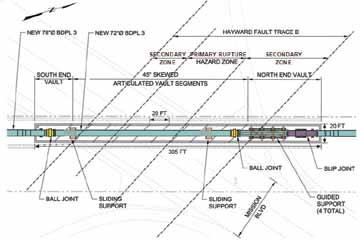
Figure 3. Plan of Trace B fault-crossing. Courtesy of URS Corporation.
secondary rupture hazard zones (Figure 2, page 39). To be conservative, it was assumed that all of the expected displacement for a particular trace will occur as a knife-edge displacement anywhere within the primary rupture zone. Trace A intersects the pipelines under a major interstate freeway and has an expected horizontal displacement of 1 foot and vertical displacement of 0.7 feet. Trace B, the main and central trace, crosses the pipe under a state highway (Mission Blvd.) and has an expected horizontal displacement of 6.5 feet. Trace C intersects the pipe in a residential neighborhood and has expected horizontal and vertical displacements of 0.5 feet. In addition to the large expected displacements, the approximately 45-degree angle at which the pipe crosses the fault traces would cause both compression and rotation forces in the pipe which are much more challenging to accommodate than tension.
Solutions
The BDPL 3 replacement consists of installing approximately 2,175 feet of new welded steel pipe (ASTM A1018 Grade 60) with a wall thickness ranging from 1 to 1.25 inches between the two existing isolation valve vaults. The new pipeline has the same inside diameter of 78 inches as the existing pipeline, except for the section that crosses Trace B which is 72 inches in diameter. Due to the differing magnitudes of expected displacement at the three traces, three different fault-crossing designs were developed. To accommodate the displacements at Trace A, the new BDPL 3 consists of 1.25-inch-thick-wall steel pipe inside of an existing 114-inchdiameter corrugated metal pipe casing under the freeway that provides rattle space for the pipe to flex and bend in response to fault movement. The annulus between the pipe casing and the pipe is filled with low-density cellular concrete. At Trace C, the new BDPL 3 has 1-inch-thick pipe walls and is buried. This new welded steel pipeline was calculated to have sufficient strength capacity for the relatively minor displacements predicted for Trace C. The large displacement of 6.5 feet expected at Trace B, which would produce a large amount of compression and rotation in BDPL 3, requires a unique and innovative design solution. Design concepts used on previous fault-crossing projects, such as the zig-zag pipeline concept used for the Denali Fault crossing of the Alyeska oil pipeline in Alaska, could not be used for this project due to space limitations. The resulting fault-crossing design consists of new 1-inch-thick wall welded steel pipe with a ball joint on each side of the fault trace and a slip joint to the north, all installed within an underground articulated concrete vault that spans both the primary and secondary rupture
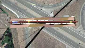
Figure 4. Trace B fault-crossing concept. Courtesy of URS Corporation.
zones of Trace B (Figure 3). The design intent is to allow the pipe to rotate at the ball joints and compress at the slip joint to accommodate the fault displacement, while the concrete vault protects the pipe within (Figure 4). The 20-foot-wide, 18-foot-high, and 305-foot-long articulated vault has 2-foot-thick reinforced concrete walls and slabs and consists of eleven vault segments separated by 6-inch-wide gaps which will allow it to “articulate” to absorb the compression and rotation from the fault displacement. Each vault segment is expected to shift transversely with respect to each other, and to also shift longitudinally to close the gaps. In plan, each of the nine 20-foot-long middle segments is shaped as a 45-degree-angle parallelogram. Both computer analyses by URS Corporation and scale-model laboratory testing at Cornell University showed that vault segments with gaps parallel to the fault perform better than segments with gaps perpendicular to the pipeline. Inside the vault, the 72-inch-inner-diameter ball joints are installed approximately 200 feet apart and are capable of accommodating 12 degrees of rotation. To the author’s knowledge, these ball joints that were specially fabricated for the project by EBAA Iron, Inc. are the largest ever built. Also specially designed and fabricated for the project, the slip joint is capable of accommodating 9 feet of contraction and 1 foot of extension, as well as an external bending moment of 55 kip-feet and shear of 32 kips which result from the design earthquake. Since no commercially-available slip joints even came close to meeting these specifications, the SFPUC conducted a nationwide search for qualified suppliers and ultimately contracted with Stress Engineering Services, Inc. to design and build the slip joint. Inside the articulated vault, the pipe is supported on various fixed, sliding, and guided supports. At the sliding supports, the pipe is welded to a steel-plate saddle with a stainless steel bottom sliding surface. This saddle sits on a concrete pedestal topped by a steel plate with a Teflon (PTFE) sliding surface that will allow the pipe to slide in any horizontal direction. The four guided supports consist of upside-down W-beam U-frames that reduce the bending moment and shear in the pipe, and allow only axial movement of the pipe in the direction of the slip joint to prevent binding. The section of pipe through the guided supports is strengthened with steel stiffener plates and fitted with stainless steel and Hastelloy sliding plates on four sides (Figure 5). The use of the highly corrosion-resistant Hastelloy alloy for the southernmost guided support was necessary to achieve a sliding surface that will maintain its low coefficient of friction long-term in the cold and damp underground vault.
Since the Trace B fault-crossing concept was newly developed for the project, the SFPUC evaluated its reliability through an extensive program of computer analysis and laboratory and factory testing. Explicit dynamic finite element analyses of the pipeline were performed using ANSYS to capture the effects of sliding friction and large axial pipeline displacements from both fault displacement and ground shaking. Parametric studies were done to test and optimize pipe wall thickness, location and number of ball and slip joints, and location and number of sliding and guided supports. The design objective was a system that would offer a high degree of seismic reliability with relatively low maintenance. To vet the articulated vault concept, soil-structure interaction analyses were performed using FLAC 3D (Fast Lagrangian Analysis of Continua) which is an advanced geotechnical software program used for continuum analysis of soil, rock and structural support in three dimensions. Concurrently, a 1/10 scale model of the vault was built and tested at the Large-Scale Lifelines Testing Facility at Cornell University. Both the computer analyses and the laboratory testing modeled the 6.5-foot fault displacement and confirmed the individual vault segments would shift and rotate to accommodate the expected ground displacement, while leaving enough rattle space for the pipe within. Lastly, vigorous factory testing of the ball joint by EBAA Iron, Inc. and the slip joint by Stress Engineering Services, Inc. were performed to demonstrate their behavior under the expected fault displacement. A third full-size ball joint was fabricated for the testing which involved rotating the joint between +8 and -8 degrees while under 200 psi of internal hydrostatic pressure. The slip joint was first hydrostatically tested to 200 psi at the three following static positions: fully extended
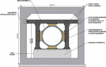
Figure 5. Cross-section of guided supports. Courtesy of URS Corporation.
at +1 feet, fully compressed at -9 feet, and in the as-installed position of zero. Then to prove dynamic performance, the slip joint was subjected to a simultaneous contraction of 9 feet, hydrostatic pressure of 125 psi, bending moment of 55 kip-feet, and shear of 32 kips. The rate of the contraction of the test was 6.25 feet in 2.0 seconds, which is the predicted speed of the fault displacement. Both the ball and slip joints performed as designed. Construction of this project by contractor Steve P. Rados, Inc. began in September of 2012 and is expected to be completed in early 2015.▪ Stephanie A. Wong, P.E. S.E., is a licensed Structural Engineer who is the lead SFPUC engineer for the Seismic Upgrade of Bay Division Pipelines 3 and 4 Project.
ADVERTISEMENT–For Advertiser Information, visit www.STRUCTUREmag.org
Toll-Free: (866) 252-4628 12080 SW Myslony St. Tualatin, OR 97062 info@albinaco.com www.albinaco.com YOUR BENDING EXPERTS
75
CELEBRATING YEARS! Est. 1939
-Angle -Flat Bar -Square Bar -Wide Flange -Channel -Square Tubing -Tee -Rectangular Tubing -Round Tube & Pipe -Round Bar -Rail -Plate

Villa Sport Athletic Club Colorado Springs, CO. Disney’s Aulani Resort & Spa Ko Olina, HI.



Atrium Roof Structural Artistry The Olin Business School at Washington University in St. Louis

By John P. Miller, P.E., S.E. and Marc A. Friedman, P.E., S.E., LEED AP
Figure 1. Interior view of completed atrium. Courtesy of Alan Karchmer.
Most structural engineers are creative in the sense of fi nding a structural solution to an architectural challenge, but they are not often thought of as artistic. Once in a great while, a design team and an owner come together and the whole is truly more than the sum of its parts. Th is was the case with the new Knight Hall and Bauer Hall, the new building for the Olin Business School on the Danforth Campus of Washington University in St. Louis. Structural engineer KPFF Consulting Engineers took an active artistic role with the architect in developing a unique roof structure. While there are many interesting structural aspects about this beautiful new $70 Million, 177,000 square foot building to accommodate faculty, numerous large classrooms, a 300-seat auditorium, and a magnifi cent multi-functional atrium space, the atrium roof structure deserves special emphasis as a work of structural art. Th e building footprint is generally U-shaped and organized around a roughly 90- by 90-foot atrium space. Tiered seating is carved from the lower fl oors of the atrium to create a forum. Th e architectural fi rm of Moore Ruble Yudell Architects & Planners of Santa Monica, CA working with Mackey Mitchell Associates and the Owner wanted this space to be light-fi lled and open, able to host large and small functions, and to serve as an informal gathering space. It was obvious that this place needed to be surrounded by a very special structure, and the atrium roof was to be the architectural centerpiece of the Olin Business School expansion project. Structural art is defi ned by three guiding principles known as the ‘Th ree Es’: Effi ciency, Economy, and Elegance. Structures that minimize the use of materials while they safely carry loads are effi cient; ones that are less costly in terms of construction are economical; and structures that are pleasing to the eye are elegant. All three of the Es must be present in a structure to be characterized as structural art. Starting with a blank canvas, the design team seized the opportunity to compose a beautiful glass-covered work of structural art.
Design Constraints
Th e atrium space was to be column-free, so the atrium roof structure would be supported on its perimeter. It was preferred not to have any roof structural systems with a bottom horizontal plane, since this would tend to reduce the soaring volume of the space. Th e west wall and part of the south wall would be all glass, and the spring-line of the atrium roof structure would be a few feet above the surrounding U-shaped main building. Th erefore, there would be no rigid perimeter means to resist horizontal thrust from the roof structure, and these forces would need to be resolved internally. It was also desired to have some roof surfaces angled to the south or vertical to regulate the sun, add ventilation, or to use for solar arrays. Because this roof structure would be on the interior of the building footprint, at the farthest reach from both of the tower cranes, it would be important to be able to erect the structure in small, manageable sections.
Evolution and Symbology of the Roof Form
Elegant and mysterious. Th ese were the two words Buzz Yudell of Moore Ruble Yudell used to describe what the atrium roof structure should be within the context of the building. Th e roof form evolved by studying
Figure 2. Buff sketches showing conceptual evolution of the atrium roof structure.
numerous structural concepts, generally categorized as “compression type” and “flexural type.” Compression type forms rely on stiff perimeter members to resist horizontal thrust and vertical deflections, while the members that span over the space are generally in compression. Several different compression type structural concepts were studied, including wood and steel lamellas, various arched notions, and several configurations of steel domes. All of these roof structures were quite elegant, and they could be made relatively thin and soaring, but they all required uneconomical perimeter framing to resist thrust and deflection. None of them were particularly mysterious, meaning one could look up at it and immediately resolve the forces with the eye. Flexural type forms rely on bending stiffness of the structure to resist vertical loads. A series of flexural type structural concepts were imagined such as arching trusses, various pin-connected trusses, and undulating flexural members. While these designs minimized the thrust problem and were relatively efficient and economical, they encroached into the volume and were fairly common looking. A breakthrough came one day with a roll of yellow tracing paper, and sparked a very iterative design process between KPFF and Moore Rubel Yudell. What if two arches leaned on each other? Why not move them to the corners, where the compression could be resolved? Then the arches were pulled apart, vertical surfaces were created by lowering a roof plane surface on both sides, and the leaning arches became curved trusses. The spaces in between were filled with various forms of flexural secondary members that had very little thrust, which set up an interesting visual hierarchy. Now we had a soaring roof with the spatial focus of a dome, but with a dynamic modern expression. The curved trusses also recall the iconic form of St. Louis’s Gateway Arch, just seven miles east, which is a symbol of the westward expansion of the country.
Geometric Basis of the Roof Form
In order to accurately model, analyze, render, and ultimately construct the roof structure, geometric parameters needed to be established that resemble the art form. Figure 3 illustrates the intersection of two sloping planes and a cylinder, forming two ellipses. These ellipses define the top chords of the elliptical trusses. To form the bottom chords of the elliptical trusses, two more sloping planes intersect vertical surfaces projecting through the top chords (Figure 4).
Structural Flow of Forces
Secondary trusses collect load from the glass panels and deliver it to the elliptical trusses and the perimeter ring beam. The elliptical trusses, primarily through axial compression, carry the load to the corners of the structure where the perimeter ring beam resolves the forces in tension. The top HSS chords of rod trusses at the center of the roof also serve as compression struts between the elliptical trusses.
Structural Loading and Analysis
The atrium roof structure was modeled and analyzed using RISA 3D. Load cases and load combinations were defined using ASCE 7-05. Load cases include dead, live, snow, wind, seismic, and temperature. In particular, unbalanced snow and wind loads were given careful consideration. In total, 197 load combinations were analyzed. Basic loads were applied as line loads to the secondary members. Steel rods were modeled as Euler buckling members. The elliptical trusses consist of a round HSS18 top chord, 6-inch standard pipe verticals, rectangular HSS bottom chords, and steel rod web members. The trusses are separated by ten feet at their apexes. Three pipe X-braces connect the two elliptical trusses at their apexes to resist unbalanced vertical loads. The secondary infill members between the elliptical trusses are generally of two types: parallel-chord steel trusses and rod trusses, the depths of which vary in proportion to their span length. The steel trusses span one direction and form sloping planar roof surfaces on the north and south sides of the roof, and are comprised of rectangular HSS top chords to receive the glass roof panels, with steel pipe bottom chords and diagonal web members. All truss panel points and top chord bridging elements align with the glazing system they support. The steel trusses are designed to be as small as possible to achieve lightness, and so bottom chord compression under wind uplift is resisted by almost invisible bottom chord wire bracing. The rod trusses were inspired by many iconic glass buildings around the world, such as the glass pyramid at the Louvre in Paris, France. Rod trusses were used in the atrium roof where it is a cylindrical form and they form a two-way system. The webs of these trusses in the north-south direction lie in a plane perpendicular to the cylindrical surface of the roof. All bottom chords and diagonals of the rod trusses
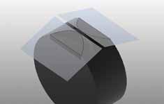
Figure 3. Geometric basis of elliptical truss top chords. Figure 4. Geometric basis of elliptical truss bottom chords. Figure 5. Structural flow of forces in primary roof members.
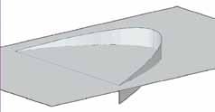
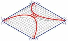
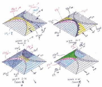
Figure 6. Examples of wind pressure load cases.
are designed for the predicted compression and tension forces under various unbalanced and uplift load cases, and the depth of each truss varies according to its span. The rod trusses have rectangular HSS top chords to receive the glass roof panels and round pipe verticals. The rods are all reverse threaded to their clevises so no turnbuckles are required. To reduce the compression demand to within allowable limits on the steel rod bottom chords under wind uplift conditions, steel cables anchored to building columns were added in four discreet locations to hold down the field of the curved rod trusses. A ring beam consisting of an HSS18x18 resolves the thrust from the elliptical trusses in the corners and also resists the minor amount of horizontal thrust from the secondary members. Steel columns support the ring beam vertically at each corner and intermittently around the perimeter. Slotted holes and fixed bearings were carefully arranged around the perimeter of the ring beam to anchor the roof structure for horizontal and uplift loads, and to allow for horizontal movements due to thermal changes and live loads.

Figure 7. RISA–3D model.
Documentation
KPFF chose to document this roof structure in AutoCad 2D, although study models in Revit, Sketch-Up, and AutoCad 3D were utilized. Conventional plans, sections and details were drawn to fully describe the dimensional parameters of the structure. Figure 8 shows one building section cut through the center of the cylindrical portion of the roof.
Fabrication and Erection
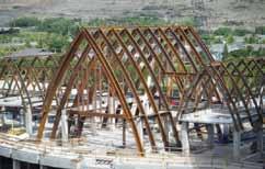
The construction manager, Tarlton Corporation of St. Louis, contracted with The Gateway Company of St. Louis to provide the detailing and fabrication of the atrium roof structure and the associated glass wall steel framing. Gateway had the elliptical pipes rolled out of town and shipped to their fab shop, where they pre-assembled most of the roof structure in their yard to assure good fit up in the field. The steel erector for the entire building, including the atrium roof structure, was Ben Hur Construction of St. Louis. In order to safely


Figure 9. Roof pre-assembly at fabricator’s yard.
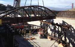
erect the atrium roof steel, along with facilitating roof glazing, sprinkler piping, fi eld painting, and electrical work, Tarlton and Ben Hur chose to build a temporary work platform just below the roof structure. Th e scaff old for this platform extended some 65 feet down through the atrium fl oor openings below, and was a signifi cant structure in and of itself. It also proved to be an invaluable benefi t to provide access for inspections of the structure. Gateway and Ben Hur collaborated and separated each of the elliptical trusses into three sections to stay within the tower crane’s load capacity. Due to careful planning, the atrium roof structure was erected quickly in a little over one month.
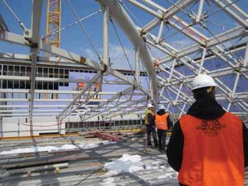
Figure 10. Temporary work platform during roof erection.
Project Team
Owner: Washington University in St. Louis Structural Engineer: KPFF Consulting Engineers, St. Louis Architect of Record: Moore Ruble Yudell Architects &
Planners, Santa Monica, CA Associate Architect: Mackey Mitchell Associates, St. Louis Construction Manager: Tarlton Corporation, St. Louis Steel Erector: Ben Hur Construction, St. Louis Fabricator: Th e Gateway Co., St. Louis
Conclusion
By listening to and embracing the artistic goals and visions of the architect, a structural engineer can provide valuable feedback and input into an artistic pursuit. Th e Olin Business School was a project in which the structural engineer was able to take an active artistic role in developing a striking work of structural art in terms of effi ciency, economy, and elegance in the atrium roof structure. Th e soaring and dynamic atrium roof structure has become the architectural centerpiece of Knight Hall and Bauer Hall.▪

John P. Miller, P.E., S.E., is one of the founding principals of the St. Louis offi ce of KPFF Consulting Engineers. John can be reached at john.miller@kpff.com. Marc A. Friedman, P.E., S.E., is an Associate at KPFF Consulting Engineers’ St. Louis offi ce. Marc can be reached at marc.friedman@kp .com.
CHATHAM UNIVERSITY EDEN HALL CAMPUS, RICHLAND TOWNSHIP, PA PHOTO BY: BLAKE INOUYE
SUPPORTING SUSTAINABILITY
IN ARCHITECTURE
Seattle • Tacoma • Lacey • Portland • Eugene • Sacramento • San Francisco • Walnut Creek • Los Angeles • Long Beach • Pasadena • Irvine • San Diego • Boise • Phoenix • St. Louis • Chicago • New York
KPFF is an Equal Opportunity Employer. www.kpff.com

FULL METAL JACKET
Part 2: Solutions
By D. Matthew Stuart, P.E., S.E., F. ASCE, F.SEI, SECB, MgtEng and Richard H. Antoine III, P.E., S.E.
Part 1 of this series discussed the investigation of an existing timber-framed, multi-story building, that is over one hundred years old, and the resulting evacuation of the occupants due to an unsafe condition at the main support columns of the building. Th is installment discusses the nature of the deterioration observed and the solutions considered for repair.
Figure 1.
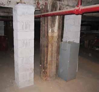
The deterioration and damage of the timber columns could be attributed to two primary causes: moisture and insects. It was unclear to what extent each column base had deteriorated, but visual observations indicated that at least three of the eight aff ected primary wood columns had lost almost all of the cross-sectional area at the base below the top of the basement slab on grade. Partial removal of the concrete slab from around the column bases at the remaining fi ve locations, to determine the extent of deterioration, was not possible because the slab in the same immediate area provided the only support for the 3x12 side plates. Th is restriction occurred because it had been observed that, as the deterioration progressed in the main building columns, the load had been transferred to the 3x12 side plates via the existing through bolts. As a result, the 3x12 side plates were beginning to exhibit localized crushing at their bases, which allowed the building to settle vertically. Th e resulting defl ection subsequently allowed the second fl oor framing to move and rotate as the columns dropped unevenly into the voids left by the deteriorated timber. Continued vertical movement was also allowed by the deterioration of the column side plates; however, at the worst areas of deterioration of the 3x12’s, masonry piers had been previously installed adjacent to the building columns (Figure 1). Unfortunately, these supplemental supports were only able to engage the fi rst fl oor framing, rather than assist with the transfer of the main building column loads from any of the other fl oors above. Solutions to the observed conditions were limited due to the lack of continuity of the beam-to-column connections throughout the building, and the unstable nature of the basement deterioration. One option that was considered initially involved shoring the columns from the basement slab up to the roof, removing the columns, and then replacing them with structural steel. Th is conventional solution was quickly ruled out after it was determined that it was not practical to remove or shore around the large fi rst-fl oor kilns that were located immediately adjacent to the columns. In addition, it was also determined that the third- and fourth-fl oor residential plans were laid out such that bathrooms, closets, kitchen countertops and other fi nishes would have to be removed in order to facilitate the temporary shoring and permanent replacement of the building columns. A second option that was considered involved strengthening the second-fl oor beams at the joint above the fi rst-fl oor columns so that the same beams could act as transfer girders to support the upper fl oors, via new columns that would be installed down to additional foundations through the fi rst fl oor and basement spaces. Th is option was also ruled out because of the precarious rotated condition of the second-fl oor beam, corbel and column joint, and the resulting diffi culty of installing adequate strengthening of the second-fl oor beams through this same joint directly above the existing adjacent kilns. It was eventually decided that temporarily shoring of the timber columns in the basement using miscellaneous steel plates and channels down to the slab on grade should be implemented until a more permanent solution could be established. Ultimately, it was determined that the best solution involved developing this temporary shoring into a permanent fi x. Initially this approach involved using through bolts to attach the steel reinforcing to the sides of the column in order to engage the wood, and transfer the entire reaction down to the slab on grade by distributing the load over a large area via steel
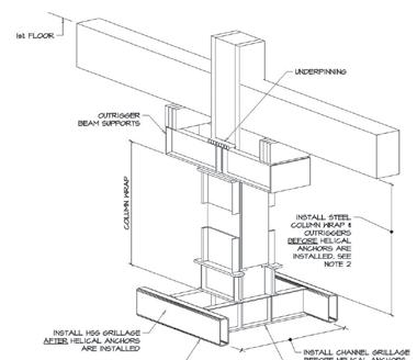

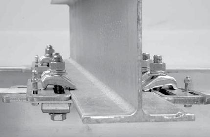
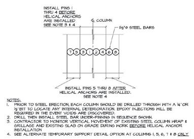
grillage. However, due to the extensive damage to the wood columns for most of the basement height, it was determined that the use of through bolts would require extensive epoxy injection in order to make the timber sound enough to engage the bolts properly. Because there was a concern that the extent of epoxy injection might result in localized failure of the adjacent deteriorated wood, and potentially cause complete failure of the column, this alternative was discarded. As a result, the final permanent solution evolved into an approach that involved abandoning the deteriorated timber column in place. This was accomplished by designing the steel reinforcing as a metal jacket built completely around each column using various steel plates and chan- Figure 3. nels (Figure 2). The jackets were prefabricated in such a way that they could be brought to the site in two pieces and then erected and bolted together around the column. Bolting the jacket assembly together was preferred in order to avoid field-welding as much as possible, due to the age and condition of the timber in the basement. The steel jackets that encapsulated the timber columns were supported at the base by a series of steel channels that transferred the vertical loads on to additional steel to stabilize the wood, and then drilling through the timber column channel grillage, which were designed to span continuously over the top and installing the steel rods one by one in the specified sequence. of the slab on grade parallel to the column centerline. The slab on grade Pre-drilling also enabled the detection of interior deterioration by was analyzed as an unreinforced section, and the steel channel grillage noting any variations in the drilling resistance encountered. The rods was arranged and extended in such a way that the modulus of rupture of were placed side-by-side such that, once all of the specified number the unreinforced concrete slab was not exceeded under the full column of rods were in place, the load from the column would be entirely design load. There were two critical assumptions that were made as a part supported by the rods and therefore transferred to the steel jacket, of the grillage design and slab on grade analysis: effectively abandoning the timber column below the rods. 1) The slab was a minimum of six inches thick. Part 3 of this series will discuss the impact of the findings of a soil 2) The soil had an allowable bearing capacity of at least 3,000 investigation that resulted in the need to develop alternate pounds per square foot. foundation solutions for the support of the steel jacket, Both of these assumptions were to be verified prior to the installation as well as repairs that were required in addition to the of the grillage. column jackets.▪ The final successful approach to avoid through-bolting of the jacket to the wood columns involved the following solutions. First, because D. Matthew Stuart, P.E., S.E., F. ASCE, F.SEI, SECB, MgtEng the first floor beams did not attach directly to the building columns, (MStuart@Pennoni.com), is the Structural Division Manager at structural steel channel outriggers were cantilevered from the top of Pennoni Associates Inc. in Philadelphia, Pennsylvania. each jacket to support the beam reactions that were being resisted by the 3x12 side plates. Timber blocking was placed between the top of the channel outriggers and the bottom of the existing beams, in order to provide an adequate load path mechanism to the steel jacket for the Richard H. Antoine III, P.E., S.E. (rantoineiii@gmail.com), was a project engineer at Pennoni Associates Inc. and is now with Jacobs in Philadelphia, Pennsylvania. first floor framing. The critical method for transferring the primary column load to the steel jacket involved the use of a series of 1½-inch-diameter steel rods that were Universal Kits for Faster & Easier Steel Connections drilled through the top of the column just below the first-floor framing. Locating the through rods at the top of the columns was determined to be a safer approach than the initial through-bolting scheme over the entire height of the columns in the basement, because the extent of existing deterioration of the wood was much less at the top of the columns than that observed over the lower portion. The methodology for installing the rods was similar to that used for underpinning an existing foundation, in that the rods were installed in a logical sequence that allowed for the progressive transfer of the column load to the steel jacket (Figure 3). • Versatile - allows for varying crossover angles • Corrosion resistant • Saves time and money no drilling or welding • Guaranteed Safe Working Loads • Will not harm protective coatings • Flush connection between both steel sections NEW! ADVERTISEMENT–For Advertiser Information, visit www.STRUCTUREmag.org This was accomplished by first pre-drilling a pilot hole, inspecting for deterioration A KEE SAFETY COMP ANY of the wood, injecting epoxy as required Fast service for info & pricing: Toll-Free: 1-888-724-2323 • www.LNAsolutions.com/Fast-Fit

Engineering Software
Working from the Cloud
New Software, Interoperability and Mobile Apps Pushing Construction Technology

By Larry Kahaner
Structural engineers are starting to see wisps of the cloud. What has become common in many industries – working from the cloud – is beginning to see daylight among those engaged in construction. “ ere are a lot of questions about the ‘cloud’ and what it means to the structural engineer,” says Raoul Karp, Vice President – Structural & BrIM, Bentley Systems (www.bentley.com/structural) in Exton, Pennsylvania. “On the information consumption side, the advantages are clear; being able to access project data authored anywhere, at any time, from any location. For example, Bentley’s Field Supervisor is the perfect companion for the structural engineer to help access all project data in the eld. In addition, Bentley Navigator provides full 3D model navigation, visualization tools, and data interrogation capabilities. Soon we will have the ability to access and manage site administration tasks, markups, RFIs, and much more from the eld. e cloud will also o er opportunities to consider more alternatives and more complex and complete solutions than ever before. Optimization across multiple disciplines is something that has existed in other industries for years, and we expect to see more of that with greater cloud analytical capacity and better optimization tools in the future.” (See ad on page 75.) At Enercalc, Inc. (www.enercalc.com) in Corona del Mar, California, President Michael Brooks says that cloud-based software is on the way. “Our products are continually enhanced according to user requests and advances in software development technology. Currently, we’ve upgraded our software to support all new building codes and we will be premiering a cloud-based software system before year’s end.” (See ad on page 3.) Other new products and services are coming along, too, says Karp. “Last year, all RAM products were updated to 64 bit, which gave our users the ability to create larger models and conduct faster analyses. Information mobility was improved with RAM Connection and RAM Concept, which are now managed directly through the RAM Structural System to provide a more uni ed and seamless work ow. Other enhancements include modeling, reporting, and analysis, including the addition of the SJI Joist Girder tables to allow consideration of joists in lateral analysis, and the addition of new ASTM A1085 and Jumbo HSS Shapes. e new release of RAM Connection included the latest design standard and seismic requirements from AISC 360-10, AISC 341-10, and AISC 358-10 for moment, brace, and HSS connection design.” He adds that Bentley’s SELECT Open Access is an industry rst that provides any subscriber with unrestricted portfolio-wide access to the company’s products. “ is allows subscribers to employ the best and most comprehensive mix of Bentley applications for all disciplines for every project. Subscribers also bene t from convenient and cost-e ective Quarterly Term Licensing at the end of each calendar quarter, as well as on-demand and live training in the virtual classroom through Bentley LEARN. With SELECT Open Access, the purchasing barriers to the most e ective software utilization are eliminated so that all Bentley applications are at your service.” As for his company’s new o erings, Brooks says that Enercalc releases updates when available and not on a regular timetable. “Instead, we are continually improving the software and releasing it through our web update system. New enhancements come in a continual ow to our Maintenance & Support Plan subscribers.” He notes: “Software trends in engineering design still follow the basic trends of all software. ese are cloud-based solutions for global deployment, incremental pricing structures to provide more cost e ectiveness to customers, and software solutions made available on multiple platforms (desktop, laptop, tablet) and multiple operating systems (Windows, Mac, Android, IOS). ENERCALC is one of the three senior structural engineering software companies, now in business for 31 years. is type of staying power re ects the necessity of the market we serve and the dedication of our long-term sta to the products and our loyal customers.” Amber Freund, Director of Marketing at RISA Technologies (www.risatech.com) in Foothill Ranch, California, says that her company has been developing world-class structural design software for over 25 years. “Our products are used to design towers, skyscrapers, airports, stadiums, petrochemical facilities, bridges, roller coasters and everything in between. e seamless integration of our product suite creates a powerful, versatile and intuitive structural design environment, ready to tackle almost any design challenge.” Freund says: “We recently released RISAFloor ES which will design one and two-way elevated concrete slabs. is addition to RISAFloor gives engineers the ability to design any commercial building within one familiar, easy to use interface. After releasing RISAFoundation,

Engineering Software
which designs mat slabs, engineers started requesting that same interface and design features in an elevated slab design program. e most requested feature, beyond the easy-to-use interface, was to be able to customize design strips. Although RISAFloor ES can automatically generate your design strips, the engineer also has the ability to modify them to t his/her design needs.” As for trends, Freund continues to see integration and interoperability being key to design projects. “We are working closely with Autodesk and Tekla to enhance our direct links so that data can be transferred seamlessly between 3D modeling, analysis-design and detailing software. Our developers, technical support group, and even our sales team are all structural engineers. Given our background, we are uniquely able to predict and meet the needs of our clients and continually produce the most user-friendly software on the market.” (See ad on page 76.) Another long-time software solutions company is Design Data (www.sds2.com) of Lincoln, Nebraska, which has been in business for over 30 years, says Doug Evans, Vice President of Sales. “SDS/2 software solutions are a suite of products developed for the manufacturing and engineering components of the construction industry. e agship product, SDS/2 Detailing, automatically designs codecompliant connections and creates shop drawings and CNC data for machines on the shop oor.” When it comes to new o erings, Evans says that SDS/2 Approval is a proven product that has been utilized in the new model approval process and is becoming increasing popular on BIM projects. “With the added ability to transfer job status, and new tools to approve and review members, this product has seen signi cant market penetration. Engineers and detailers are moving away from drawing-based methods to approve project and design intent, and embracing model-based methods to accomplish the same goal. SDS/2 Approval product provides them the right tools to work in this environment,” he says. Evans wants SEs to know about two other new products. “SDS/2 Erector combines the ability to build your own intelligent cranes with the crane building functionality and the fabricated BIM model from the manufacturer. is combination gives erectors and general contractors the needed tools to plan and organize the site to make for a smooth project.” He adds: “ e SDS/2 Detailing agship product is bringing dramatic improvement to market this year. e automatic connection design functionality now creates the ability to lock any design element, and design a connection around that variable. is gives engineers full control over every aspect of a connection. In addition, the ability to create components will increase the productivity when modeling miscellaneous elements like outriggers, conveyors and platework.” (See ad on page 44.) Evans concludes: “All of the new o erings are a direct result of the BIM work process, and utilizing the model and model data in new and innovative ways to reduce cost and improve quality in the construction cycle. A majority of the new products and features have come out of the collaborative e ort of development with our current installed base and our experienced development sta .” ere are four key trends that improve user experience: interoperability, ease of use, integration and the ability to easily automate repetitive tasks, according to Marinos Stylianou, CEO of S-FRAME Software (www.s-frame.com) in Guilford, Connecticut. “Ideally, clients want a single model for their software and tools. ey can’t a ord to move back and forth between dissimilar products and technologies. Integration is key not only at the designer or engineering level, but at the entire business level of the company and its partners. With each new release of our product suite, we continue to o er our clients tangible improvements in all four key areas.” S-FRAME recently released S-FOUNDATION, a foundation analysis and design product with automation and customization capabilities. “S-FOUNDATION has been very well received by the structural engineering community since its release in 2013, and is helping to expand our presence in the concrete analysis and design arena,” says Stylianou. “In addition, all our core products saw signi cant updates and new feature functionality with release R11. Our interoperability with BIM and CAD systems was expanded through new bi-directional links with Tekla and Revit. e DXF translator was also completely rewritten and modi ed to handle increased customer needs.” He adds: “Industry trends and demands motivate our team to provide the best state-of-the-art technology, while providing an enjoyable and simple user experience. e ability to communicate among our products, and with 3rd party and in-house products, is another driver requested by our clients. Clients are seeing a refresh in their business that requires faster concepts and better designs at a reasonable cost. Our solutions aim to address all three of these points.” (See ad on page 4.) Celebrating its 40th anniversary, Scia Engineer is part of a new breed of integrated 3D structural analysis software that makes it easy for engineers to plug analyses and designs into today’s BIM work ows, says Dan Monaghan U.S. managing director of Nemetschek Scia (www.nemetschek-scia.com) . He is based in Columbia, Maryland. “Flexibility is a big bene t of Scia Engineer. It is used by engineering companies across a numbers of industries including plant/process, buildings and transportation. It’s a great design tool for day-to-day engineering work, but has the advanced analysis capabilities and multi-material code support rms need to tackle larger, more complex projects.” e company has recently released Scia Engineer v14. “With Scia Engineer v14 we are introducing a new Open Check technology that allows rms to easily script their own custom structural calculations inside Scia Engineer’s 3D FEA environment. Giving engineers the ability to write and run their own custom checks and calculations in their structural design software is a real game changer for some rms,” says Monaghan. “It removes the dependency that rms have on any one software vendor. Engineers can now easily extend their analysis software by adding their own design checks whenever they need them. It also removes the biggest criticism that engineers have with structural engineering software: the software is too black box. With Open Checks, engineers can see the formulas and methods that are being used to derive a check. And, best of all, they can edit them to suit their own preferences or design criteria.” Simpson Strong-Tie (www.strong-tie.com) of Pleasanton, California, has worked with structural engineers for nearly 60 years providing engineered structural connectors, lateral-force resisting systems and other building solutions, says Paul McEntee, continued on page 48
Plugging Analysis and Design into Your 3D Workflow
WITH new processes like BIM (Building Information Modeling) and VDC (Virtual Design and Construction) and new project delivery methods like IPD (Integrated Project Delivery), more and more engineering firms are being asked to participate in collaborative, model-based workflows. Migrating to these new processes can be made easier with software designed to support them— software like Scia Engineer from Nemetschek. Scia Engineer is a new breed of integrated structural design software that goes beyond analysis and helps firms successfully join in today’s collaborative 3D workflows.
Fast and Efficient Modeling
Modeling is an essential requirement for any 3D workflow. As projects become more complex and project timelines compressed, modeling needs to be fast and efficient, but also not restrictive. Engineers need to be able to keep up with the modern designs coming from architects and contractors who push the limits of new materials and methods. “A unique feature of Scia Engineer is its modeling capabilities,” says Mark Flamer, M.I. Flamer & Associates. “It’s a very fast and efficient FEA (Finite Element Analysis) modeling tool. freeform modeling capabilities make it easy for me to work up designs in 3D and keep pace with my architect’s avant-garde designs. And, its parametric object technology has allowed me to automate routine and repetitive work. I can quickly work up and test design concepts. Then, when the design has gelled, I can develop an accurate structural model in Scia Engineer or link my design to another BIM program for model coordination or construction drawings.” With support for open standards like IFC 2x3 and direct links to a number of BIM software programs, Scia Engineer makes it easier for engineers to reuse models created by others and leverage them into analysis. This is a huge advantage when working in a collaborative workflow. “For the new National Music Centre project in Calgary, Canada, the architect made frequent and sometimes dramatic changes,” says Andrea Hektor, KPFF Portland. “We needed to be able to give them a quick thumbs up or thumbs down on their revised designs. With Scia Engineer it was great. The architects would just send us their updated models. We would import them into Scia Engineer, update our model, run a quick analysis, and give them enough information to continue moving forward. I don’t think we would have been able to do this with any of the other analysis software we have in our office.” Another advantage of Scia Engineer is its extensive functionality. Analysis and design is becoming more rigorous, and owners are looking for highly optimized structures to minimize materials, construction time, and costs. Being able to have one program that is efficient for your day-do-day work, and at the same time offers the ability to handle complex analysis tasks is a big benefit. “With support for advanced FEA analysis and multi-material design I’ve avoided having to invest in disparate analysis programs,” continues Flamer. “Reducing the number of analysis programs we manage saves on maintenance costs and makes it less expensive to train new employees. Most importantly, it reduces the risks that come with manually coordinating multiple analysis models. For occasions when I need to go outside Scia Engineer, the program’s Open Design technology, allows me to script my own checks to expand its built-in design capabilities.”
Growing with Technology
In addition, the right software makes a firm more flexible, allowing them to go beyond their usual projects, and take on work wherever they find it. “Scia Engineer allows our firm to confidently compete for bigger building projects as well as go beyond buildings,” says Flamer. “While our expertise is in commercial, we just completed a bridge project and are ready to take on larger, complex structures. A flexible tool like Scia Engineer makes all the difference.” He added: “I evaluated the usual list of structural analysis programs, and there isn’t another program in the market like it. Scia Engineer is the only program I found that integrates fast and efficient modeling, lets me script my own calculations, and easily reuse and share 3D models. For us, Scia Engineer was a logical choice.”
Daniel Monaghan is the U.S. Managing Director of Nemetschek Scia, developers of leading software products for AEC software industry. He can be reached at dmonaghan@scia-online.com When Modeling Matters, Scia Engineer Delivers
“More in tune with the engineer’s workflow”
“Eye-opening”
“Extremely impressed”
Read the AECbytes Article
www.nemetschek-scia.com/review
Scia Engineer is a new breed of integrated structural design software that goes beyond analysis to help firms excel in today’s collaborative 3D workflows.
Discover fast, efficient modeling and intelligent FEM analysis. Recycle and leverage models created by others into analysis. And, centralize your design tasks with static and advanced nonlinear and dynamic analysis, plus multi-material design in ONE program.
Request your FREE Trial.

Engineering Software
Engineering R&D Manager. “Today, we o er a full line of structural products that help customers design and build safer and strong homes and buildings to resist high winds, hurricanes and seismic forces. We also continue to focus on technology by providing free software, web and mobile apps, online calculators and other resources to help structural engineers design and model projects using our products.” e company has announced a new software program for coldformed steel design that automates product selection and helps navigate the complicated design provisions of AISI, while o ering more robust design tools for users, according to McEntee. “ e new program has an upgraded user interface that makes input faster and more intuitive. CFS Designer software is the new version of LGBEAMER, a software program that has been one of the most widely-used CFS member design tools in the industry. e new streamlined software gives structural engineers the ability to design CFS beam-column members according to AISI speci cations, and to analyze complex beam loading and span conditions.” McEntee adds: “With our new Literature Library mobile app, it’s easier than ever for engineers to take Simpson Strong-Tie product information on the go. With the Literature Library app on iPhone, iPad and Android devices, SEs can now access and download all catalogs, iers and technical bulletins to a mobile device, bookmark the pages they use most, create a customized library on their device, and view downloaded documents without Wi-Fi.” In addition, the Simpson Strong-Tie Strong Frame moment frame selector software is designed to help engineers select an ordinary or special moment frame for their project’s given geometry and loading. McEntee says that only minimum input geometries are required for the software to select an appropriate frame for the available space. “Based on input geometry, the Strong Frame selector software will narrow down the available stock frames to a handful of possible solutions. If opening dimensions are outside stock frame sizes, designers can enter the speci c opening dimensions and the Strong Frame selector will provide possible customized solutions. “We also have updated the Holdown Selector web app so it is available in U.S. and Canadian versions. e Holdown Selector web app is a quick and easy tool that selects the most cost-e ective holdown connector based on the type of installation, demand load and the wood species of the post,” McEntee says. Although not a software company, Ram Jack (www.ramjack.com) o ers many products and tools for engineers, including software. Ram Jack is a helical and hydraulically-driven steel manufacturer and distributer, says Darin Willis, Director of Engineering for the Ada, Oklahoma-based company. “Ram Jack has an international network of franchises throughout the U.S., Canada, Puerto Rico and South America. We o er a wide arsenal of brackets and pilings that are available for almost every situation.” In addition to its free, web-based helical design software, Foundation Solution, Ram Jet also o ers: • An engineering department sta ed with structural and geotechnical engineers who are available to assist with pile designs, provide calculations, shop drawings or answer any technical questions. • An engineering portal on Ram Jack’s website that provides product shop drawings of their most common brackets and piles, standard speci cations and general notes for helical and hydraulically-driven piles. It also has procedures for designing helical piles in accordance with the International Building
Code, ICC ESR report. Engineers can contact the engineering department directly for any additional assistance. • Free Lunch and Learn presentations in most locations. e presentations cover the theory and application of helical piles.
Most state engineering boards accept continuing education credits based on the technical presentations. • To further guarantee quality control and assurance to its clients, Ram Jack’s manufacturing and distribution arms have both received certi cation for ISO 9000 compliance. “Even though helical piles have been used for more than 175 years, most engineers were not educated on how to design them during their college curriculum,” Willis says. “ e last 25 years has seen exponential growth in the use of helical piles and tieback anchors. e ICC adopted the acceptance criteria for helical piles in June 2007, and included helical piles in the 2009 and 2012 IBC. e Lunch and Learn’s technical information provided on the engineering portal, the design software and the engineering support, are in place to help engineers understand the design theory, capacities and applications of this valuable tool.” (See ad on page 50.) StructurePoint, LLC (www.structurepoint.org) in Chicago, Illinois, was formerly the Engineering Software Group of the Portland Cement Association, and is a dedicated team of engineering professionals committed to excellence, continuous improvement, and service, according to Marketing Director Heather Johnson. “We provide civil and structural engineers with the software and technical resources they need for designing concrete buildings and structures. StructurePoint is a convenient single point of access to the vast resources and knowledge base of the entire cement and concrete industry including library services, training, R&D, publications, building codes, specialty engineering services, concrete material and testing, concrete repair, codes and standards consulting.” StructurePoint’s primary focus is concrete structures. “We are watching closely every code change and amendment relevant to concrete design. We are also behind the scenes looking for important upcoming changes to make concrete design simpler, faster, and more accurate. We do it once and well, so that every engineer knows that at least his concrete design is optimal, economical, safe and code compliant,” Johnson says. “In spColumn v4.81, StructurePoint has further re ned slender column design provisions to meet stringent new requirements of ACI-318.” Business has been improving, says Johnson. “Companies of all sizes and geographies have been increasingly more upbeat about business opportunities, and cement shipments have been growing steadily indicating more construction spending. Among our users, geotechnical engineers have been exceptionally active responding to exploding opportunities in oil, gas and petrochemical projects. ese opportunities continue to drive additional demand of our spMats and spBeam program for foundations in industrial facilities and infrastructure construction.” (See ad on page 51.)

Engineering Software
e Canadian Wood Council (CWC) (www.woodworks-software.com) is the national association representing Canadian manufacturers of wood products used in construction. CWC’s main priority is to ensure that building professionals such as engineers, architects, and other design professionals have the needed information to specify and use wood products in a safe, secure, and code-compliant manner, according to Josée Lalonde, Marketing & Sales Coordinator. “One way we do this is through our wood engineering software, WoodWorks. Separate Canadian and U.S. versions of WoodWorks software are available. For the U.S. version – compatible with the IBC, NDS, SDPWS, and ASCE7 – CWC works closely with the American Wood Council (AWC) to ensure consistency in technical interpretations,” says Lalonde. In the United States, the latest version of the software is US Design O ce 10 (SR2a), released in February, 2014. is version conforms to the 2012 IBC, the 2012 NDS, and the 2010 ASCE-7. Also, new features added to the February release of the Shearwalls program are: • Worst-case design of shear walls considering wind and seismic loads. Envelopes the worst case distribution (rigid and exible diaphragm), providing the designer with an immediate assessment of whether the walls meet all the desired design criteria.
• Reduced processing time. e software was capable of doing increasingly complex calculations. For very complex buildings the run time was as long as 10 minutes. It has been reduced to 20 seconds. In Canada, a new release (Cdn Design O ce 9) is scheduled for August. Says Lalonde: “ is version will include improvements made in the US DO 10, including allowing pdf and bitmaps to be used as templates for modeling the building in the Shearwalls program, highlighting walls that are over capacity, and grouping user-de ned walls together to ensure a consistent design. Additionally, an expanded list of Canadian cities will allow designers to select any of the over 600 cities listed in the NBC 2010 Design Data, which automatically populates most of the wind and seismic data needed, and, at the push of a button, determine the lateral loads on the structure.” (See ad on page 53.) According to Stuart Broome, Business Manager, Engineering at Tekla (www.tekla.com), the Kennesaw, Georgia company is focused on building and construction. Its customers are in the architectural, engineering and construction (AEC) markets and include structural engineers, contractors, fabricators and steel detailers. “ e company was established in 1966, and today it has customers in 100 countries, o ces in 15 countries, and a global partner network. In 2011, Tekla continued on page 52
ADVERTISEMENT - For Advertiser Information, visit www.STRUCTUREmag.org


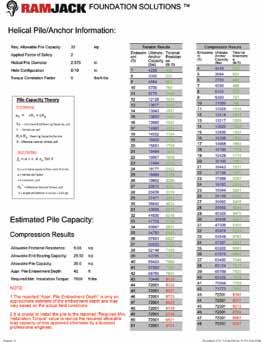

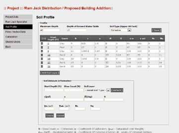


EnginEEr DEsign softwarE: founDation solutions™
Create Profiles
• Simulate soil profile • Anchors with varying diameter and helix configurations • Vertical/battered/tie-back pile design • Custom pile design
Mobile-friendly
• Web-based software • Use anywhere, anytime • Laptop, iPad, iPhone, tablets
www.ramjack.com/software 888-332-9909


Share & Report
• PDF Output for submittals • Share projects with other registered users


Engineering Software
became part of Trimble Buildings Group and then, in 2013, Trimble acquired CSC which is now incorporated into Tekla,” he says. “Launched in 2004, Tekla Structures is the preferred tool of construction professionals around the world to model, detail, fabricate and build many of the world’s buildings, bridges, and sports complexes. e software is designed to work seamlessly with Tekla BIMsight, a free online tool and portal for construction project collaboration,” Broome says. “ e most recent version, released in March, brings even more detailed information and exibility to modeling while reducing the need for manual data transfer. Information now ows more e ciently from design, purchasing and production to the shop oor. Tekla also provides more links to architectural and design solutions to remove the technical and compatibility barriers that compromise work ow between project teams and subcontractors using di erent types of applications.” For more information and to download Tekla Structures 20 go to www.tekla.com/tekla-structures-20. In June 2014, Tekla released Tedds 2014, a new version of its calculation production suite which automates the design and documentation of structural components. “A major new development to Tedds 2014 is the inclusion of the Tedds Project Manager,” Broome notes. “Project Manager allows users to create a project of related Tedds documents that can easily be managed directly within Tedds. Teams using Tedds are able to work even more e ciently by using Project Manager to streamline their work ows and administration, and create dynamic reports directly from the Project Manager.” Fastrak, another o ering, is a steel building design tool. It is a physical object-based modeling solution which automates the requirements of AISC360 and ASCE7, according to Broome. He says that the main reasons why clients use Fastrak are: • e ability to model and automate the design of composite oors and complex roof structures/trusses in one model and in one interface • e ability to model and automatically design gravity and lateral systems in one model and in one interface • e ability to synchronize a design model with a Revit model and pass information in both directions, as many times as required, in a manageable way. Broome concludes: “Our solutions contribute to the essential processes of today’s information-intensive construction industry. Ultimately, it comes down to collaboration and sharing of information. We continually add new features to help our clients work e ciently. BIM is increasingly becoming common practice and it’s vital that we o er our clients a cutting-edge BIM solution so that they can increase their productivity, win more work and be more pro table.” (See ad on page 56.) ▪
SOFTWARE GUIDE BIM, Bridges, Building Components, Business/Productivity, CAD, Concrete, Found./Retain. Walls, Gen./Packages/Suites, Light Guage Steel, Masonry, Steel, Wood
ADAPT Corporation
Phone: 650-306-2400 Email: info@adaptsoft.com Web: www.adaptsoft.com Product: ADAPT-PT RC Strip Design Description: e most popular software for design of post-tensioned slabs and beams now includes a Reinforced Concrete design option. is new capability lets engineers use the strip design software they are already used to on all their concrete projects, saving time and the hassle of switching between software. Product: ADAPT-Builder with Column Design Description: An integrated analysis and design software for concrete buildings that now includes code check and design capabilities for columns. Use it to e ciently analyze and design your complete concrete building from foundation to roof slab all in one model – post-tensioned or mild reinforced. Seamlessly integrates with Revit Structure. Product: ADAPT-ABI 4D Construction Phase Analysis Description: 4D construction phase analysis of concrete bridge or building structures. Models construction phases including temporary structures, closure strips, pre- and post-tensioning. Reports forces, creep, shrinkage and de ections using nonlinear material behavior. Great tool for calculating long-term e ects, camber, super-positioning, and investigation of construction methods. Applied Science International, LLC
Phone: 919-645-4090 Email: tdigirolamo@appliedscienceint.com Web: www.appliedscienceint.com Product: Extreme Loading for Structures Description: An advanced non-linear structural analysis software tool designed speci cally for structural engineers. Easily study static and dynamic loads such as those generated by blast, seismic events, impact, progressive collapse, and wind. Product: SteelSmart System (SSS) Description: Available as a complete suite, SSS will streamline production through the design and detailing of members, connections, and fasteners. Available design modules include: Curtain Wall, Load Bearing Wall, X-Brace Shear Wall, Floor Framing, Roof Framing, Roof Truss, and Moment-Resisting Short Wall.
Bentley Systems
Phone: 610-458-5000 Email: katherine. esh@bentley.com Web: www.bentley.com Product: ProConcrete Description: Advanced 3D CAD program for modeling, detailing, scheduling of reinforced insitu/ precast and post-tensioned concrete structures. O ers simple and easy-to-use tools for advanced 3D modeling of reinforced concrete structures, producing automated design and detail drawings and rebar schedules. Enables engineers to reduce documentation production time. Product: LEAP Bridge Steel Description: An integrated, 3D Steel bridge design and rating program. It provides comprehensive layout, geometric modeling, design, analysis, and load-rating for small to medium steel bridges. is intuitive software complements Bentley’s LEAP Bridge Enterprise for concrete design with Bridge Information Modeling (BrIM) for steel bridge design. Product: STAAD Foundation Advanced Description: Comprehensive foundation design program which o ers the ability to model complex or simple footings, including those speci c to Plant facilities: octagonal footings supporting vertical vessels, strap beam foundations supporting horizontal vessels, ring foundations supporting tank structures, and drilled or driven pier foundations.
CADRE Analytic
Phone: 425-392-4309 Email: cadresales@cadreanalytic.com Web: www.cadreanalytic.com Product: CADRE Pro 6 Description: Finite element structural analysis application for Windows. Solves beam and/or plate type structures for loads, stress, displacement, and vibration modes. Advanced features for stability, buckling, dynamic analysis and shock. Complete seismic analyses to comply with current codes. Special provisions for unusual structural types such as geodesic domes. continued on page 54
Computers & Structures, Inc.
Phone: 510-649-2200 Email: info@csiamerica.com Web: www.csiamerica.com Product: SAP2000, CSiBridge, ETABS and SAFE Description: Computers & Structures, Inc. develops leading structural and earthquake engineering software used in more than 160 countries worldwide. From simple building structures to complex long-span bridges, CSI products do it all with a balance of practicality and sophistication.
Concrete Masonry Association (CMACN)
Phone: 916-722-1700 Email: info@cmacn.org Web: www.cmacn.org Product: CMD12 Description: Structural design of reinforced concrete and clay hollow unit masonry elements. For design of masonry elements in accordance with provisions of Ch. 21 – 1997 UBC, 2001 – 2013 CBC or 2003 – 2012 IBC and 1999 – 2011 Bldg. Code Requirements for Masonry Structures (TMS 402/ACI 530/ASCE 5).
Decon USA
Phone: 707-996-5954 Email: frank@deconusa.com Web: www.deconusa.com Product: Jordahl Anchor Channels Description: Software allows a user friendly and safe calculation for anchoring in concrete with JTA anchor channels. Features a technical and economical optimization of the design for each individual connection. 3D graphics are easy to use and allow a fast and clear input of all data. Product: Studrails® Description: A free design software for Studrails called STDESIGN 3.1. e software can be downloaded from our website and complies to ACI 318, ACI 421.1 and CSA A23.3. PC based and excellent for e cient and veri able output on punching shear reinforcement.
Design Data
Phone: 402-441-4000 Email: marnett@sds2.com Web: www.sds2connect.com Product: SDS/2 Connect Description: Enables users of Revit Structure for BIM to intelligently design steel connections and produce detailed documentation on those connections. SDS/2 Connect is the only product that enables structural engineers to design and communicate connections based on their Revit Structure design model as part of the fabrication process.
Devco Software, Inc.
Phone: 541-426-5713 Email: rob@devcosoftware.com Web: www.devcosoftware.com Product: LGBEAMER v8.0 Description: Analyze and design cold-formed cee, channel and zee sections. Uniform, concentrated, partial span and axial loads. Single and multi-member designs. 2007 NASPEC, including the 2010 Supplement (2013 IBC) compliant. Pro-Tools include shearwalls, framed openings, X-braces, joists and rafters. Enercalc, Inc.
ENERCAL C
Phone: 800-424-2252 Email: info@enercalc.com Web: www.enercalc.com Product: Structural Engineering Library Description: A proven solution to all the typical, repetitive and daily design tasks performed by structural engineers. By carefully combining building code provisions, proven analysis techniques, and standard materials into simple and elegant software, you can quickly design, analyze, or optimize all your daily design tasks.
FabTrol Systems, Inc.
Phone: 541-485-4719 Email: info@fabtrol.com Web: www.fabtrol.com Product: FabTrol Pro Description: Steel Fabrication Management Software
Hilti, Inc.
Phone: 800-879-8000 Email: us-sales@hilti.com Web: www.us.hilti.com Product: PROFIS Anchor and PROFIS DF Description: PROFIS Anchor performs anchor design for cast-in-place and Hilti post-installed anchors using ACI 318, Appendix D provisions. PROFIS DF Diaphragm optimizes design of steel deck roof and oor diaphragms using the SDI Diaphragm Design Manual, 3rd Edition provisions.
IES, Inc.
Phone: 800-707-0816 Email: sales@iesweb.com Web: www.iesweb.com Product: VisualAnalysis Description: Engineers have enjoyed solving problems with our easy-to-use, exible, general analysis tool. With 20-years of customer-tuning, you will wonder why you struggled with anything else.
Integrity Software, Inc.
Phone: 512-372-8991 Email: sales@softwaremetering.com Web: www.softwaremetering.com Product: SOFTRACK Description: Provides Calendar Hour control for all your Bentley applications and helps you reduce or eliminate quarterly trust licensing overage billings by Bentley.
Losch Software Ltd
Phone: 323-592-3299 Email: LoschInfo@gmail.com Web: www.LoschSoft.com Product: LECWall Description: Concrete column and sandwich wall design and analysis. Includes handling design, prestressed and mild reinforcing.
MadSoftware, Inc.
Phone: 720-362-2470 Email: info@madsoftware.net Web: www.madsoftware.net Product: AxisVM Description: Advanced Visual Modeling for most engineered structures. Linear, Non-Linear, Buckling, Vibration, Seismic, Dynamic analysis. The Masonry Society
Phone: 303-939-9700 Email: info@masonrysociety.org Web: www.masonrysociety.org Product: Masonry Codes and Guides Description: e 2013 edition of the code and minimum speci cation is now available. A major update from the 2011 edition both in technical requirements and in layout. is edition will be referenced by the 2015 ICB for the design and construction of structural masonry, veneer, and glass unit masonry.
National Concrete Masonry Association
Phone: 703-713-1900 Email: dgraber@ncma.org Web: www.ncma.org Product: Direct Design Software Description: Using the IBC and IRC-referenced standard Direct Design Handbook for Masonry Structures (TMS 403-13), this software package allows users to generate nal structural designs for whole concrete masonry buildings in minutes. Product: Structural Masonry Design Software Version 6.1 Description: Now updated to include the 2012 International Building Code and 2011 MSJC. Includes new larger allowable stresses per code. Designs walls, columns, lintels and much more. Product: SRW Design Software – SRWall Description: Superior segmental retaining wall (SRW) designs produce superior results. Stay on the cutting edge of SRW design with the latest industry standard design tools. 30-day free trial download.
Nemetschek Scia
Phone: 877-808-7242 Email: info@scia-online.com Web: www.nemetschek-scia.com Product: Scia Design Forms Description: Engineers can easily script custom calculations and output professional reports showing the exact formulas used to derive a check. Checks can be run as stand-alone, or linked to Scia Engineer. Imagine being able to write checks linked your FEA software. Download the FREE trial.
Product: Nemetschek Scia Description: Request a FREE tryout and plug structural analysis and design into today’s 3D work ows. Tackle larger projects with advanced nonlinear and dynamic analysis. Design to multiple codes and script your own custom checks. Plug into BIM with links to Revit, Tekla, and others.
Powers Fasteners
Phone: 985-807-6666 Email: jack.zenor@sbdinc.com Web: www.powers.com Product: Powers Design Assist (PDA) Description: Enables users to input technical data into a dynamic model environment; to specify anchors. PDA-360 is a FREE online version of our popular anchor design software. Powerful calculations with fast, detailed results. Works with any popular internet browser or mobile device.
RISA Technologies
Phone: 949-951-5815 Email: info@risa.com Web: www.risa.com Product: RISA-3D, RISAFloor and RISAFoundation Description: Developing cutting-edge structural design software for over 25 years, RISA software products are used around the world for buildings, stadiums, bridges and everything in between. RISA-3D, RISAFloor, and RISAFoundation allow you to work with steel, concrete, timber, masonry, aluminum and cold-formed steel in a single, seamlessly integrated model.
S-FRAME Software
Phone: 203-421-4800 Email: info@s-frame.com Web: www.s-frame.com Product: S-FRAME R11 Description: S-FRAME Analysis, an industry standard for over 30 years, is a powerful, e cient 4D structural analysis and design environment with fully integrated steel, concrete and foundation design and optimization tools. Use S-FRAME to perform linear or advanced non-linear analysis on buildings and industrial structures. Includes advanced BIM and CAD links.
Product: S-FOUNDATION Description: Design, analyze and detail foundations with S-FOUNDATION, a complete foundation management solution. A stand-alone application, or utilize S-FRAME Analysis’ powerful 2-way integration links for a detailed soil-structure interaction study. Automatically manages the meshed foundation model and includes powerful Revit and Tekla BIM links.
Product: Structural O ce R11 Description: Model, analyze and design robust structures regardless of geometric complexity, material type, loading conditions, nonlinear e ects, or design-codes. Integrated steel, concrete, and foundation design solutions have e cient data sharing and include powerful two-way Revit and Tekla BIM links and comprehensive DXF le import capabilities.
Simpson Strong-Tie
Phone: 925-560-9000 Email: web@strongtie.com Web: www.strongtie.com Product: Simpson Strong-Tie® CFS Designer™ Software Description: Software for cold-formed steel designers automates product selection and helps navigate the complicated design provisions of AISI, while o ering more robust design tools. e program has an upgraded user interface that makes input faster and more intuitive. CFS Designer is the new version of LGBEAMER software.
Product: Simpson Strong-Tie® Joist Hanger Selector Web App Description: is web app makes it easier than ever to select the most cost-e ective hanger for your projects based on the type of installation, sizes and loads. e clean, visual interface enables users to quickly select the members and con guration for their desired connection, and print the results. Standards Design Group, Inc.
Phone: 800-366-5585 Email: info@standardsdesign.com Web: www.standardsdesign.com Product: Wind Loads on Structures 4 Description: Performs computations in ASCE 7-10 and ASCE 7-98, computes wind loads by analytical method rather than the simpli ed method, provides basic wind speeds from a built-in version of the wind speed, allows the user to enter wind speed. WLS4 has numerous specialty calculators. Product: Window Glass Design 5 Description: Performs all required calculations to design window glass according to ASTM E 1300-09, ASTM E 1300 02/03/04, ASTM E 1300-98/00 and ASTM E 1300-94. GANA endorses WGD5 as best tool available in designing window glass to resist wind and long-term loadings.
Strand7 Pty Ltd
Phone: 252-504-2282 Email: anne@beaufort-analysis.com Web: www.strand7.com Product: Strand7 Description: Advanced, general purpose, FEA system used worldwide for a wide range of structural analysis applications. Strand7 can be used as a standalone system, or with Windows applications such as CAD software. It comprises preprocessing, solvers (linear and nonlinear, static and dynamic) and postprocessing.
Structural Engineers Inc.
Phone: 540-731-3330 FLOORVIBE Email: tmmurray@ oorvibe.com Web: www. oorvibe.com Product: FloorVibe v2.20 Description: Proposed oor designs can be analyzed to determine if they meet the AISC Design Guide 11 and the SJI Technical Digest No. 52nd Ed. using FloorVibe v2.20. Floor framing can be hot-rolled, joists, or built-up sections. Expert advice provided for all required input and results.
StructurePoint
Phone: 847-966-4357 Email: info@structurepoint.org Web: www.StructurePoint.org Product: spWall and spColumn Description: spWall – For analysis design and investigation of reinforced concrete, precast, ICF, tilt-up, retaining and architectural walls. spColumn – design and investigation of rectangular, round, and irregular concrete columns including slenderness e ects.
Product: spSlab and spMats Description: spSlab – For analysis, design, and investigation of elevated reinforced concrete beams, joist, one-way, two-way and slab band systems. spMats – For analysis, design and investigation of concrete foundations, mats, combined footings, pile caps, slabs on grade, underground and buried structures. Struware, LLC
Phone: 904-302-6724 Email: email@struware.com Web: www.struware.com Product: Steel Floor Vibration Analysis Description: Analyzes oor systems in accordance with AISC Design Guide 11 and can compare up to 4 systems side by side. Demos at website.
Product: Tilt-up Walls and CMU Walls Description: Tilt-up analyzes wall strips, CMU analyzes solid walls for out of plane loading, but both will also analyze panel legs next to openings by automatically calculating loads to the wall leg from vertical and horizontal loads at the opening. Demos at website.
Product: Struware Code Search Description: Provides all pertinent wind, seismic, snow, live and dead loads for your building in just minutes. Simpli es ASCE 7 & IBC (and codes based on these) by catching the buts, ifs, insteads, footnotes and hidden items that most people miss. Demos at website.
Tekla Inc.
Phone: 770-426-5105 Email: info.us@tekla.com Web: www.tekla.com Product: Fastrak Description: Dedicated software to automate the design and drafting of steel buildings. Design simple and complex buildings to US codes and then export models directly to BIM compatible software, such as Tekla Structures.
Product: Tedds Description: Perform 2D frame analysis, access a large range of automated structural and civil calculations to US codes and speed up your daily structural calculations.
USP Structural Connectors
Phone: 800-328-5934 Email: uspcustomerservice@mii.com Web: www.uspconnectors.com Product: USP Speci er Description: Simpli es access to information on over 3,000 structural connectors. Looking up connector capacities, viewing code evaluation reports and even mapping from competitor products to USP products are a snap with just a couple of clicks. Download the FREE USP Speci er software at the website.
WoodWorks® Software
Phone: 800-844-1275 Email: sales@woodworks-software.com Web: www.woodworks-software.com Product: WoodWorks Design O ce 10 Description: Conforms to IBC 2012, ASCE7-10, NDS 2012, SDPWS 2008; SHEARWALLS: designs perforated and segmented shearwalls; generates loads; rigid and exible diaphragm distribution methods. SIZER: designs beams, columns, studs, joists up to 6 spans; automatic load patterning. CONNECTIONS: Wood to: wood, steel or concrete.
Not listed? Visit www.STRUCTUREmag.org and submit your information for upcoming guides! Listings are provided as a courtesy. STRUCTURE magazine is not responsible for errors.


